Electronique Telematique ETELM Canada BSTETRA460 Tetra Base Station User Manual netis B maintenance guide V1 1
Electronique Telematique ETELM Canada Inc Tetra Base Station netis B maintenance guide V1 1
UserManual.wiki
>
Electronique Telematique ETELM Canada
>
BSTETRA460 User Manual
>
netis B maintenance guide V1.1.part3
Contents
1.
netis B maintenance guide V1.1.part1
2.
netis B maintenance guide V1.1.part2
3.
netis B maintenance guide V1.1.part3
4.
netis B maintenance guide V1.1.part4
5.
relevant regulatory warnings
6.
Internal Photos 460.025-464.025 MHz
7.
NetisB25 460.025-464.025 MHz Parts list
netis B maintenance guide V1.1.part3
Navigation menu
Upload a User Manual
Namespaces
Wiki Guide
HTML
PDF
Info
Views
User Manual
Discussion / Help
Navigation


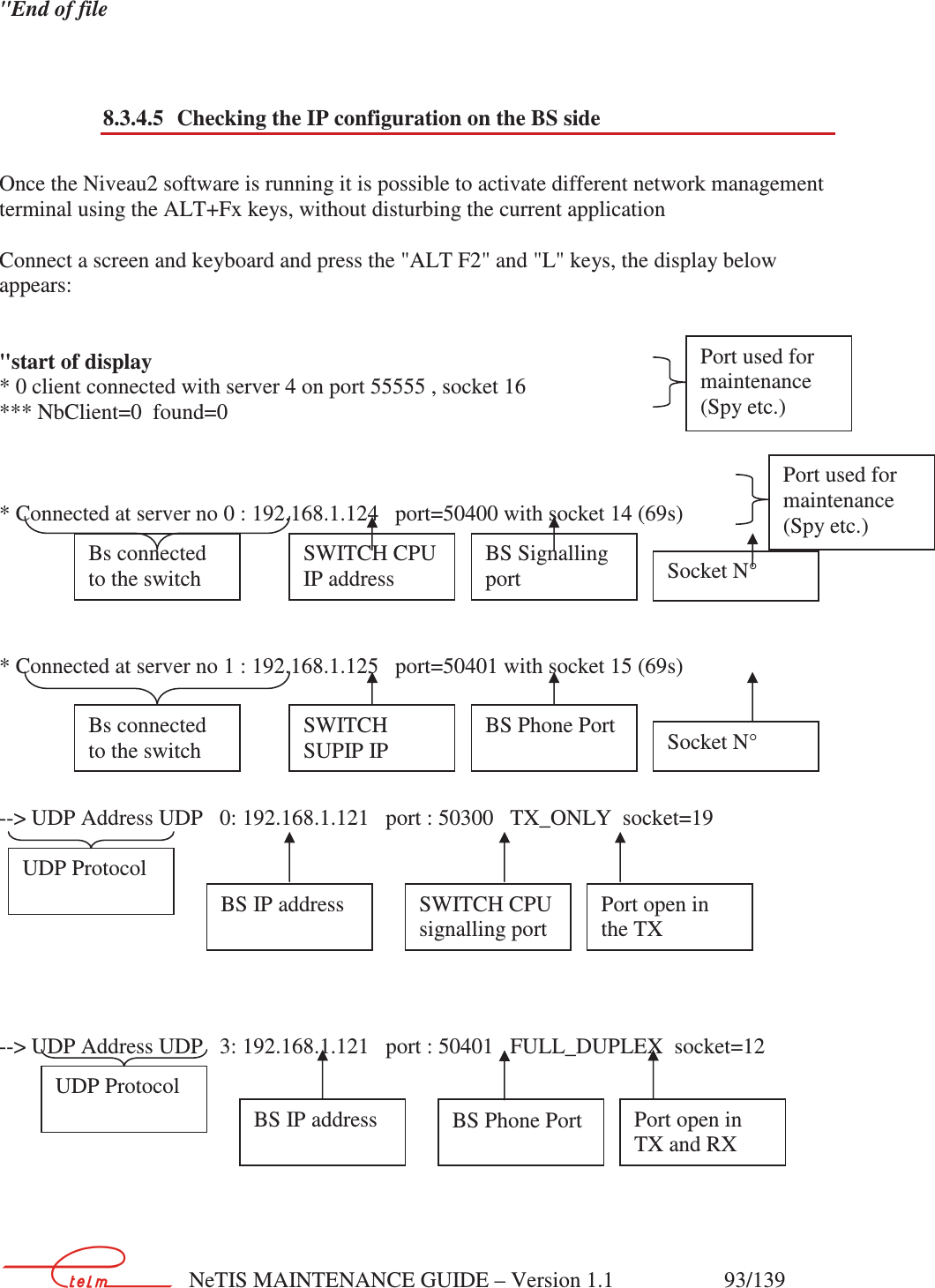
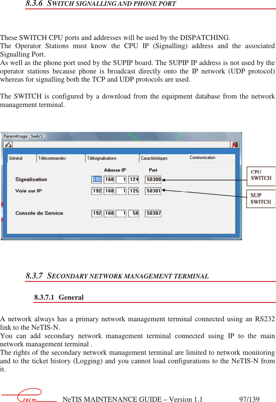
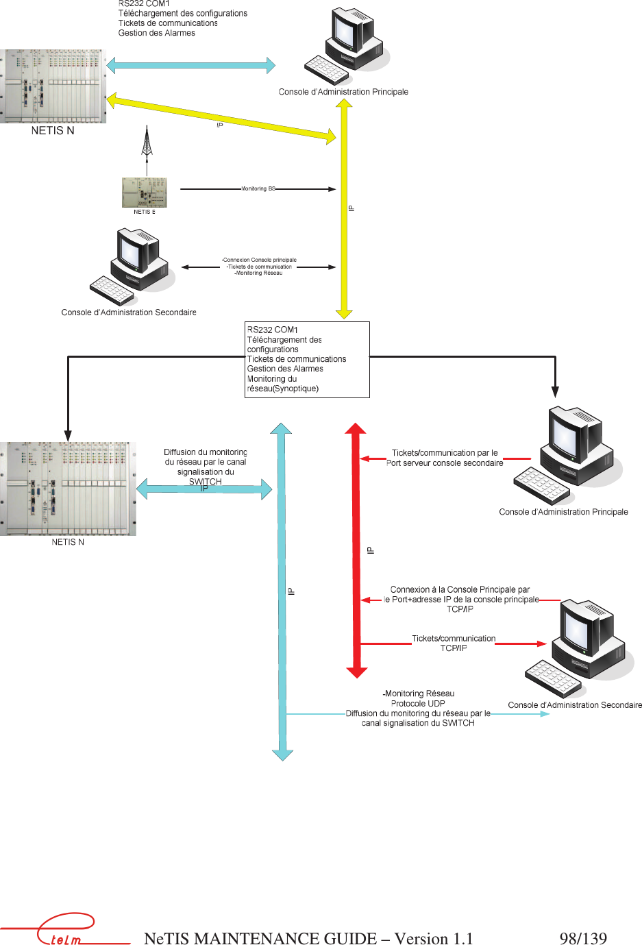
![NeTIS MAINTENANCE GUIDE – Version 1.1 92/139 8.3.4.3 Port identification declaration on the NeTIS-B side A base station that wants to connect to the tetra network listens on its identification port in order to obtain the information from the different SWITCHES on the network with their priority level. To declare this port, a configuration file (Text) stored on the NeTIS-B must be read the path of which is /USR/BsLinux/nano CONFIGBS.CFG. Below the content of the CONFIGBS.CFG file shows that the identification port is "51114" "Top of file ######### IP PARAMETERS PORT_IDENTIFICATION = 51114 [ Read 62 lines ] ^G Get Help ^O WriteOut ^R Read File ^Y Prev Page ^K Cut Text ^C Cur Pos ^X Exit ^J Justify ^W Where Is ^V Next Page ^U UnCut Txt ^T To Spell "End of file 8.3.4.4 IP Network without using the identification port If the port is not filled in in the BS, then port "51114" is used as a default. It is not mandatory to use the identification port. If you know the SWITCH IP addresses (CPU and SUPIP) and the signalling and phone ports that are used, then they can be added to the CONFIGBS.CFG file as shown below. "Top of file ######### IP PARAMETERS IP_SWITCH = 192.168.1.100 PORT_SWITCH = 50020 IP_SUPIP = 192.168.1.3 PORT_SUPIP = 50021 [ Read 62 lines ] ^G Get Help ^O WriteOut ^R Read File ^Y Prev Page ^K Cut Text ^C Cur Pos ^X Exit ^J Justify ^W Where Is ^V Next Page ^U UnCut Txt ^T To Spell IDENTIFICATION PORT N° Commands to close the file for example: CTRL X(^ X) ACTIVE SW CPU+signalling port ACTIVE SW SUPIP+Phone port (§9.3.4.5)](https://usermanual.wiki/Electronique-Telematique-ETELM-Canada/BSTETRA460.netis-B-maintenance-guide-V1-1-part3/User-Guide-3010374-Page-22.png)