Electronique Telematique ETELM Canada BSTETRA460 Tetra Base Station User Manual netis B maintenance guide V1 1

Electronique Telematique ETELM Canada Inc Tetra Base Station netis B maintenance guide V1 1

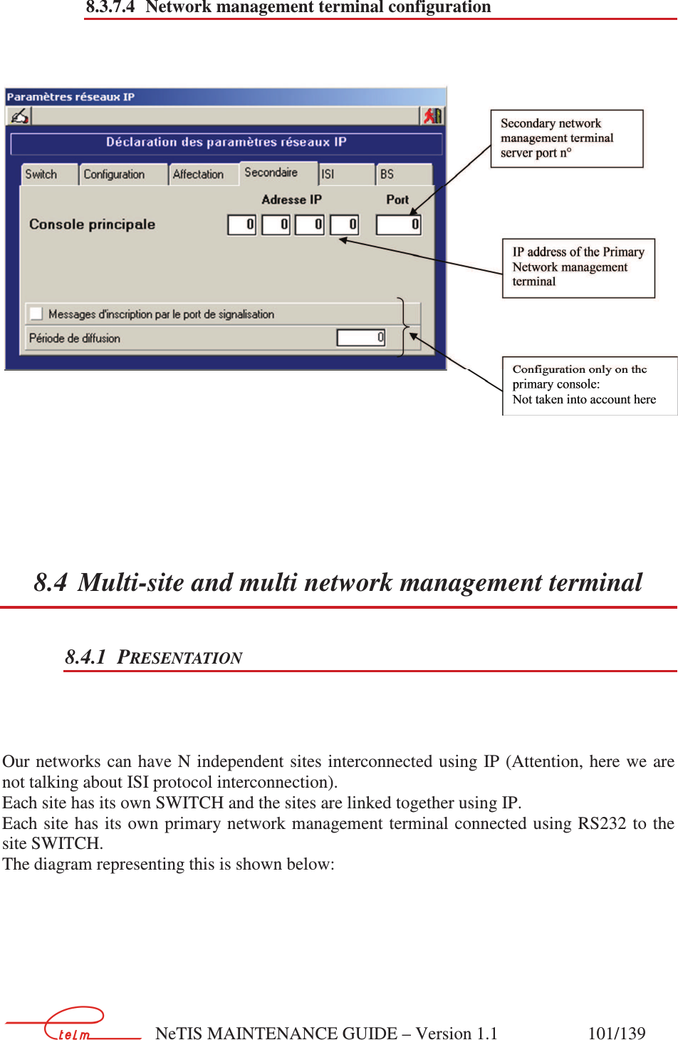
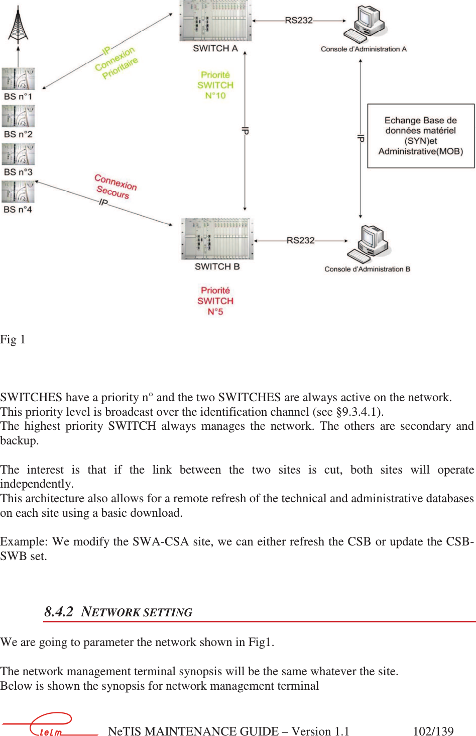
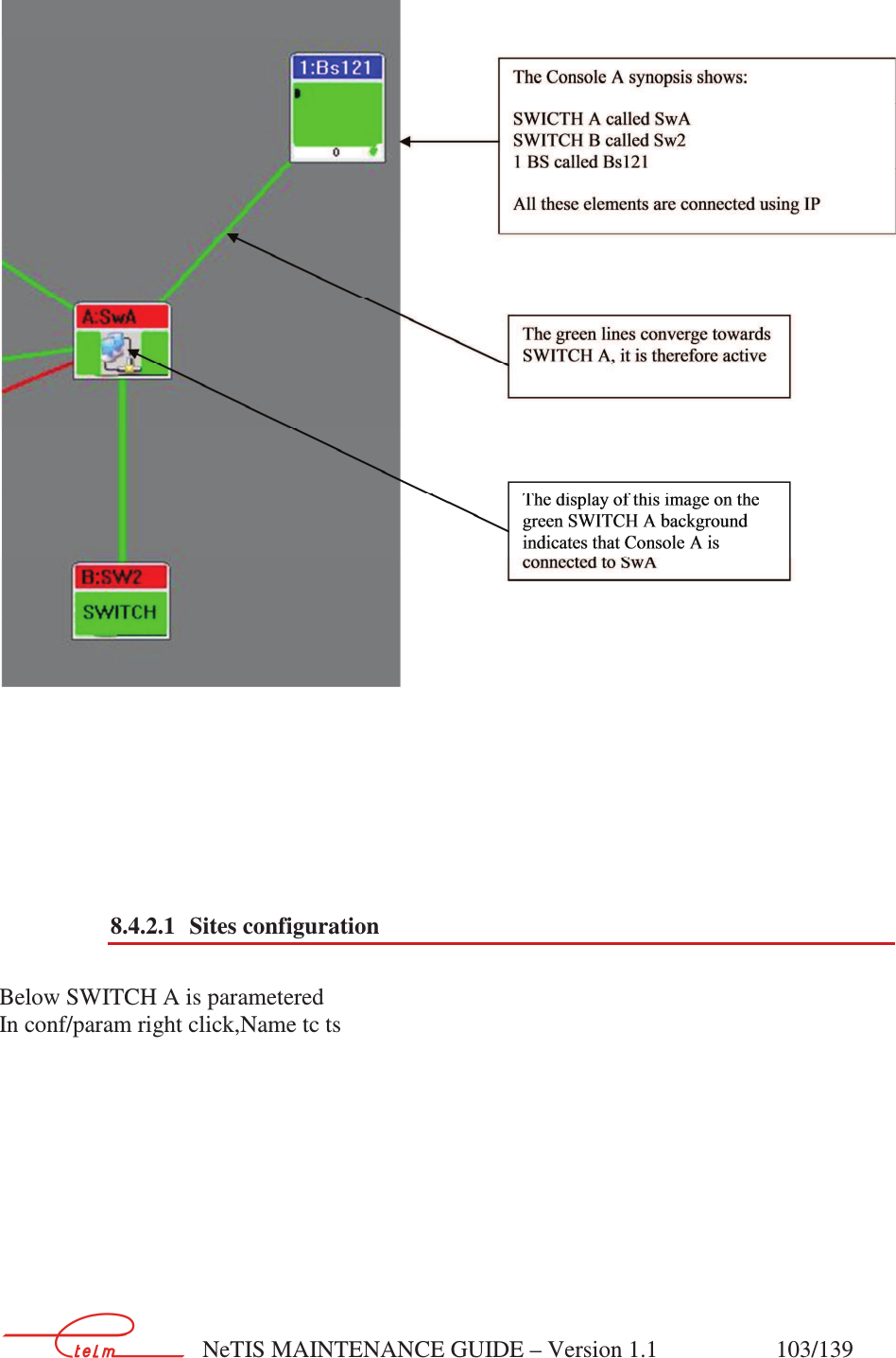
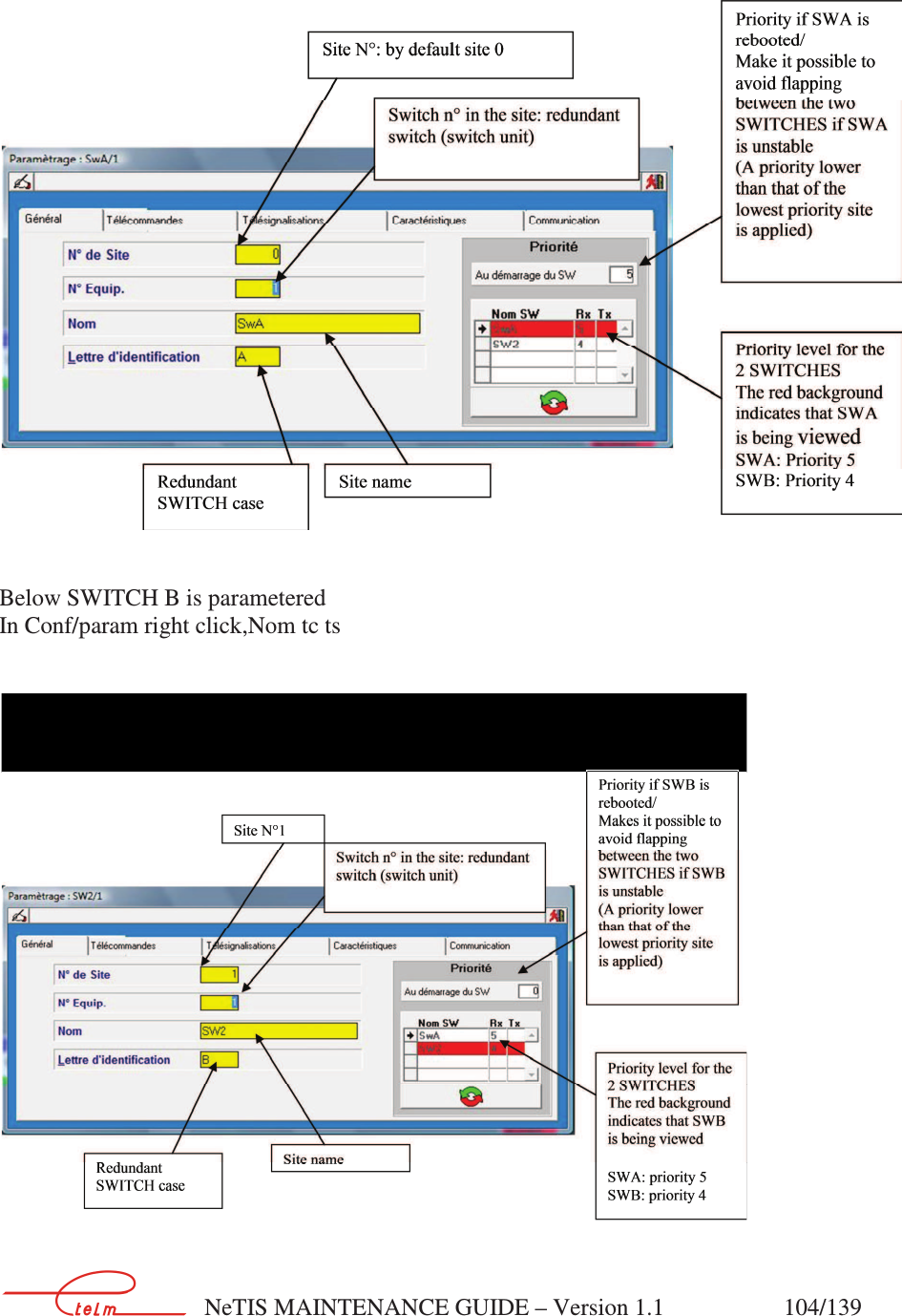
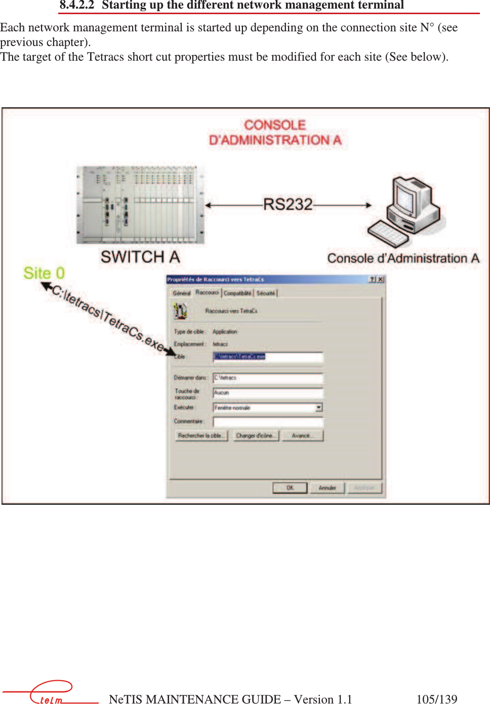
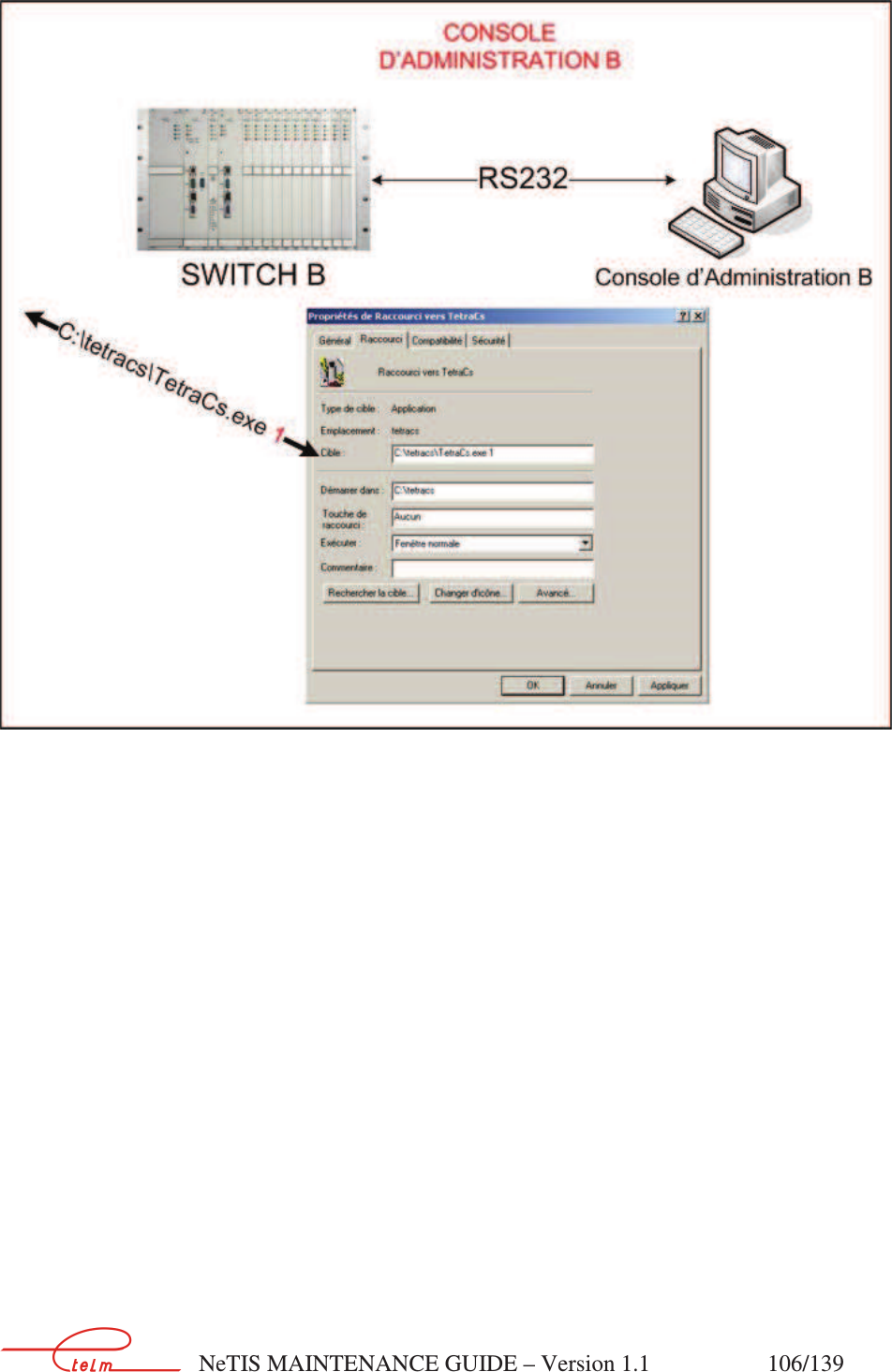
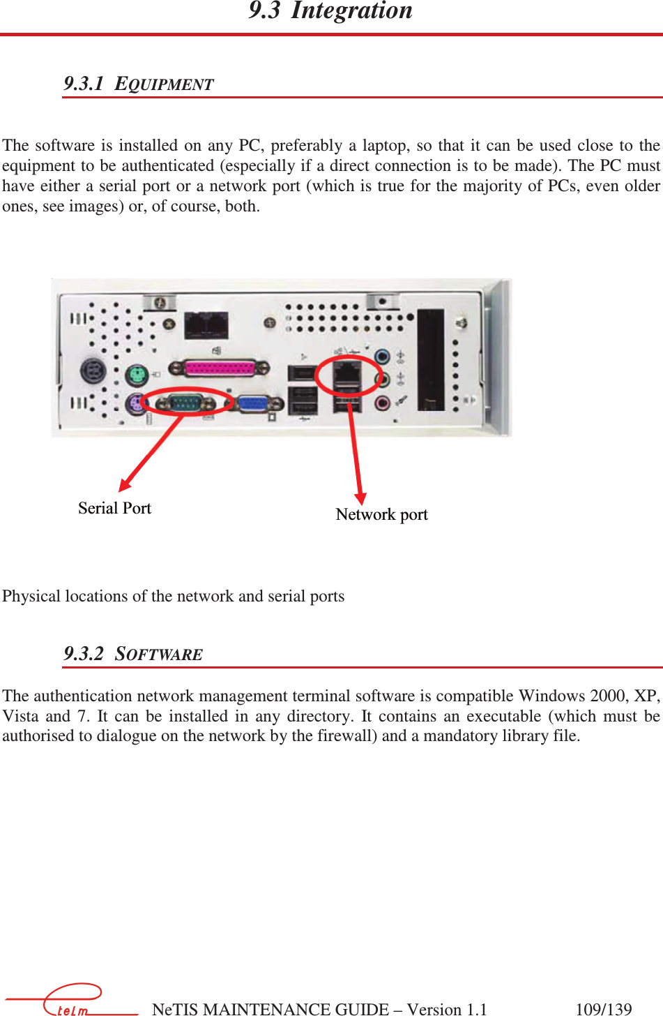
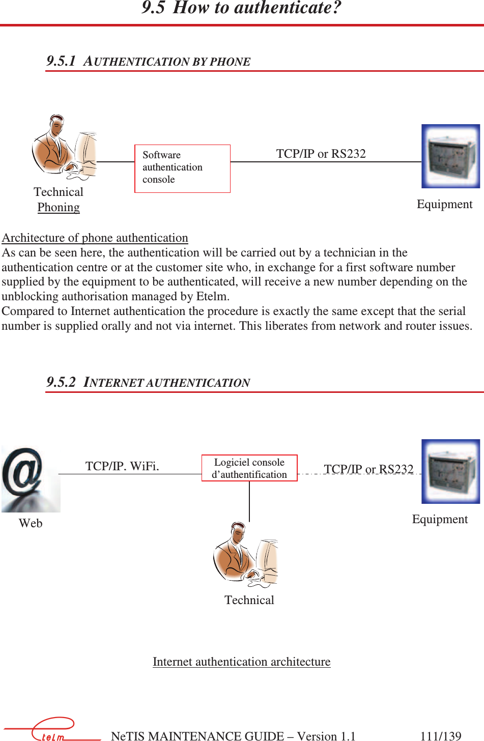
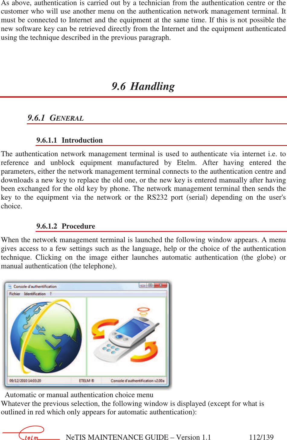
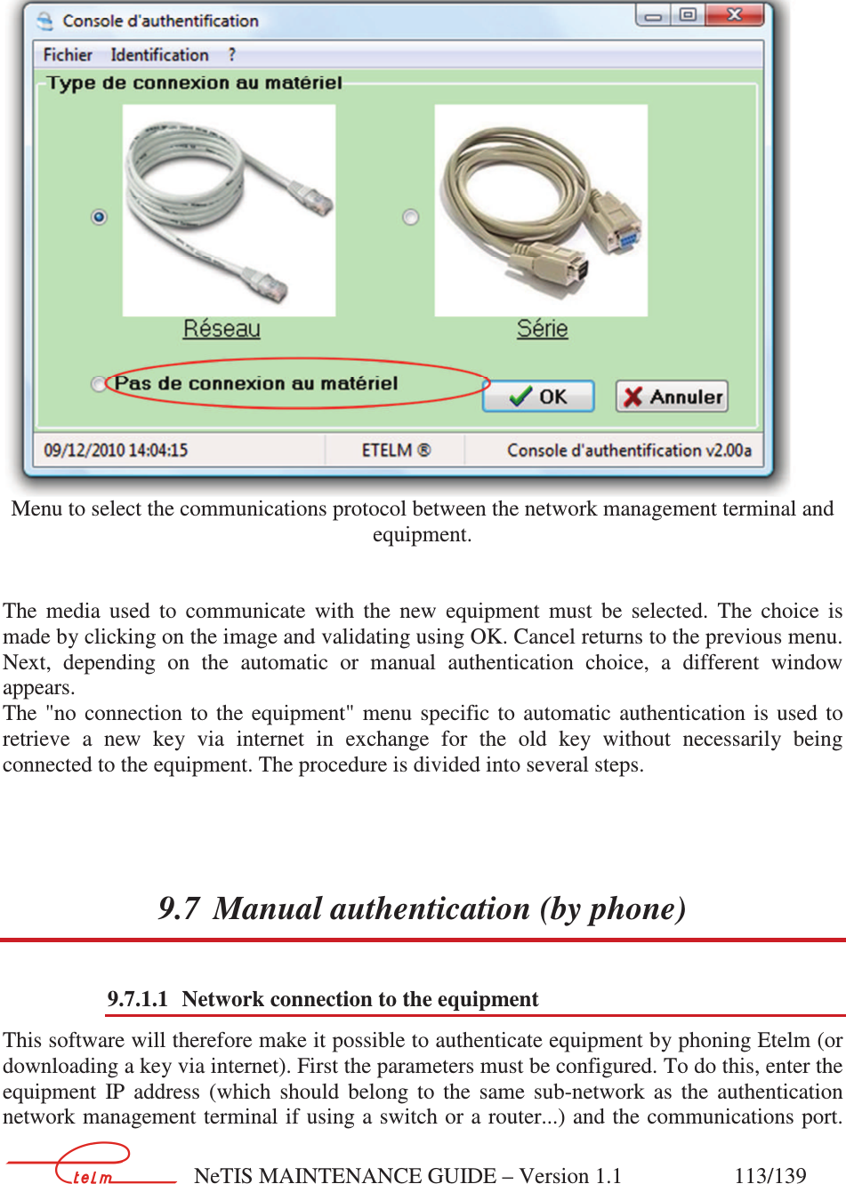
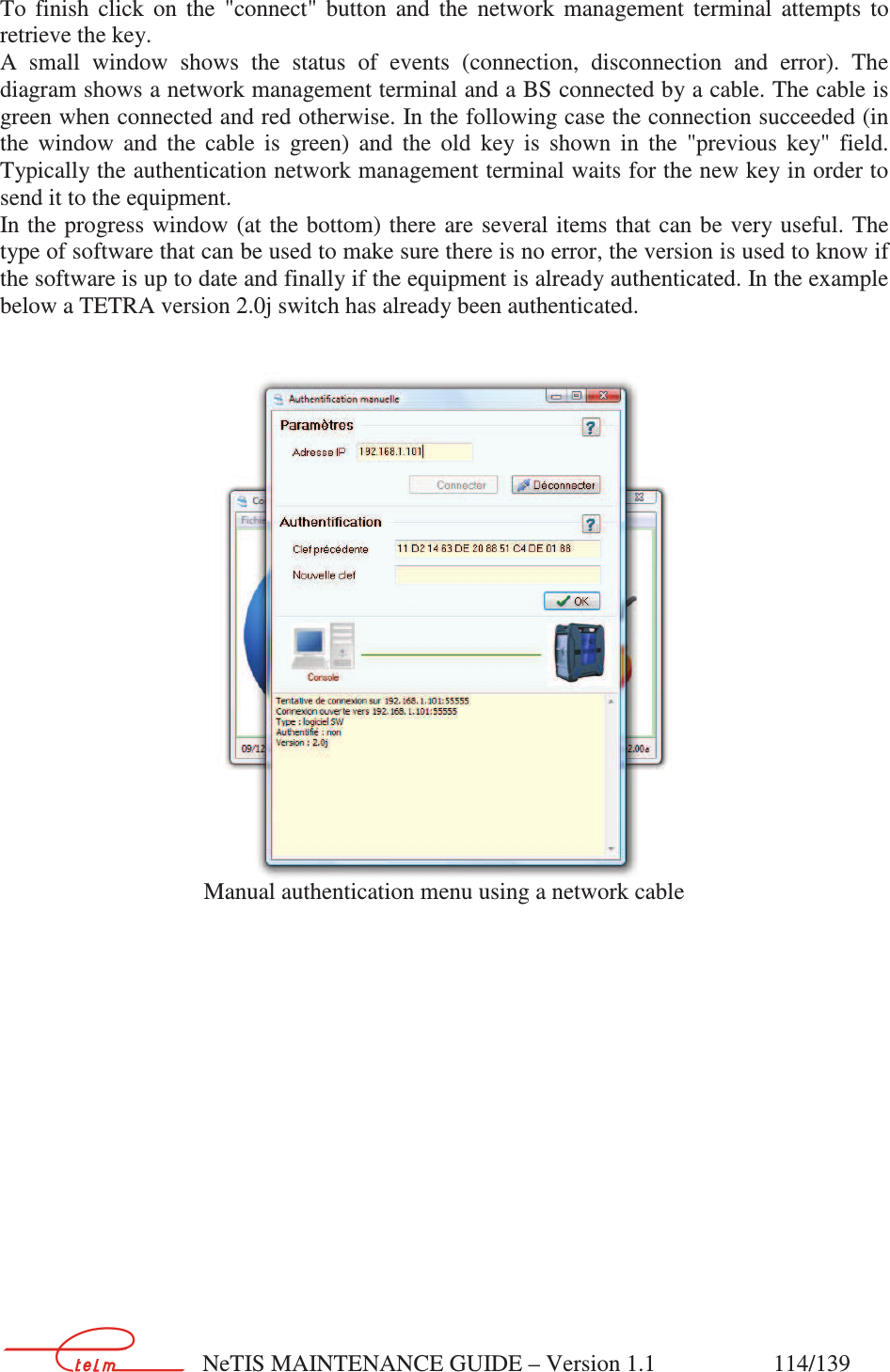
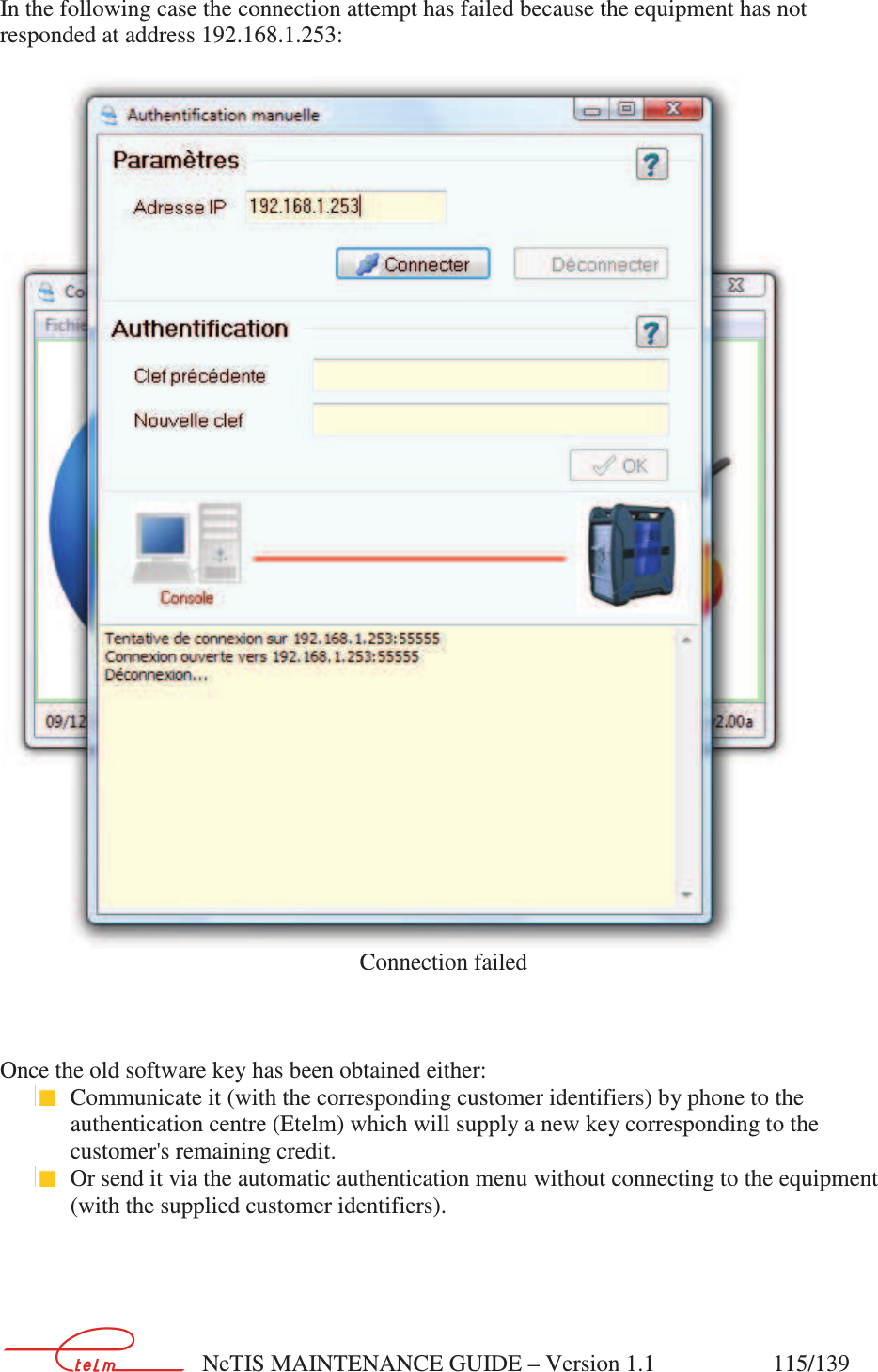
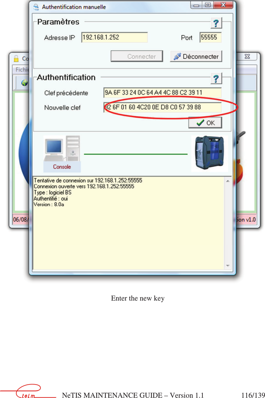
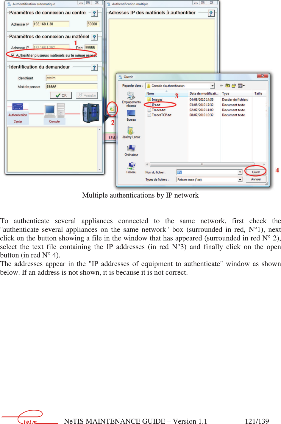
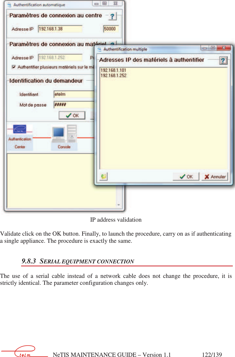
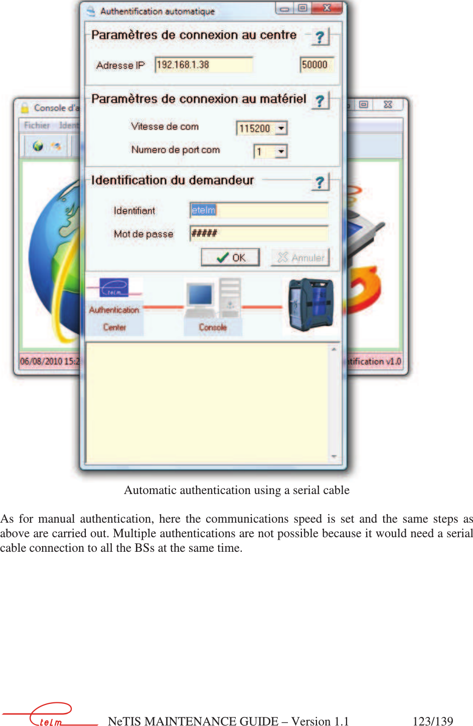
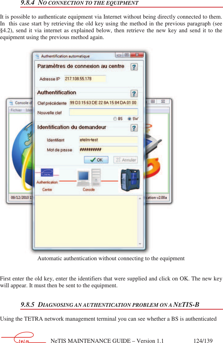
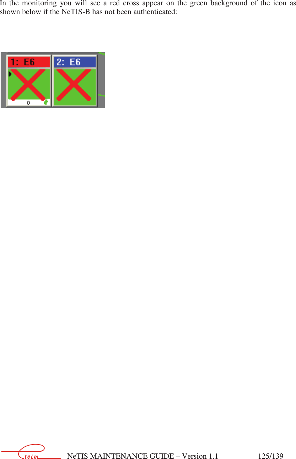
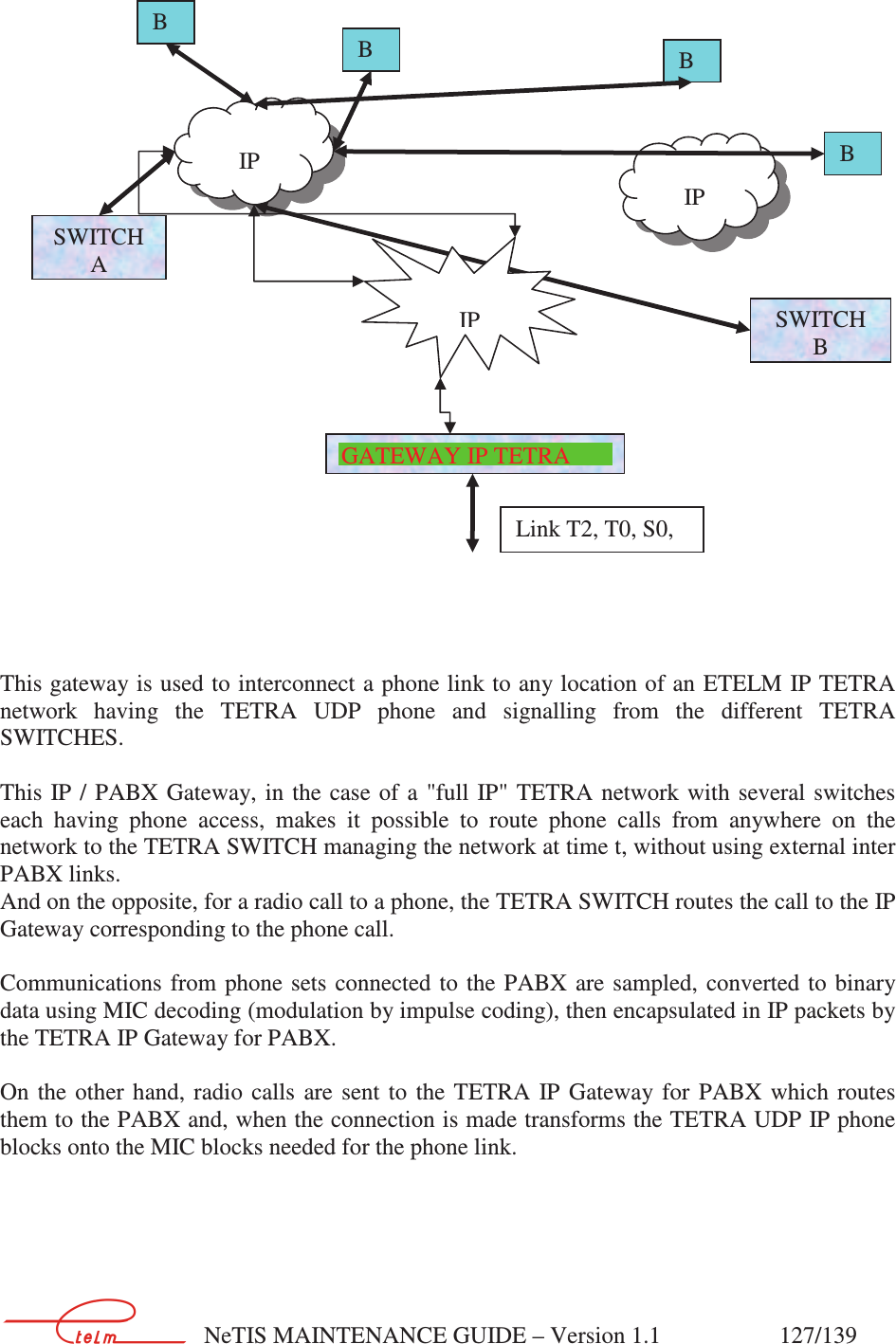
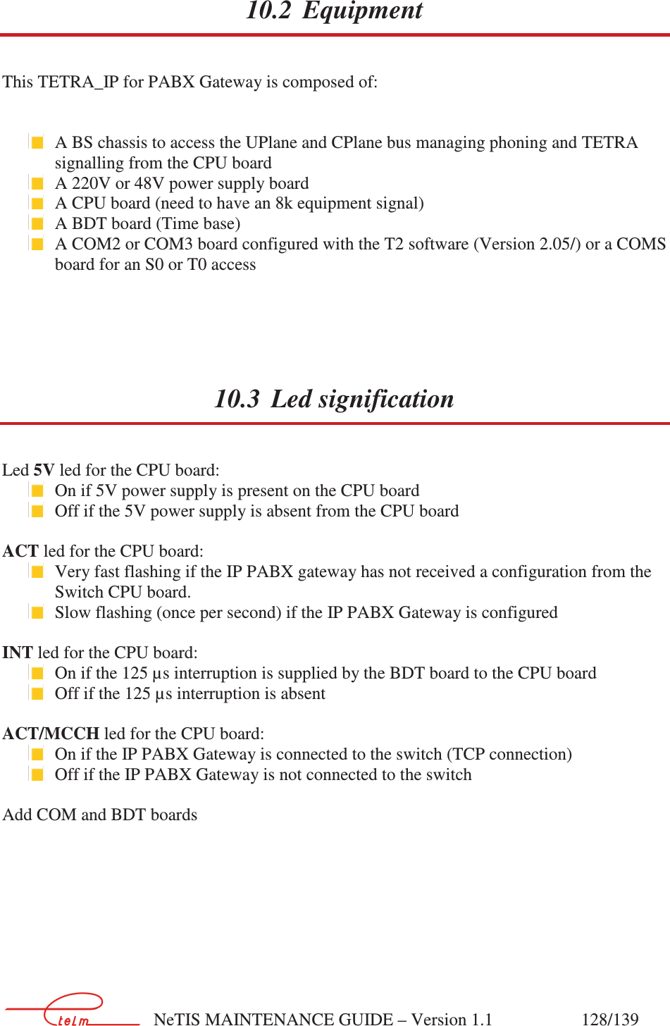
netis B maintenance guide V1.1.part4

       NeTIS MAINTENANCE GUIDE – Version 1.1                    101/139   8.3.7.4 Network management terminal configuration      8.4 Multi-site and multi network management terminal 8.4.1 PRESENTATION    Our networks can have N independent sites interconnected using  IP (Attention, here we are not talking about ISI protocol interconnection). Each site has its own SWITCH and the sites are linked together using IP. Each site has its  own primary network management terminal connected using RS232 to  the site SWITCH. The diagram representing this is shown below:
       NeTIS MAINTENANCE GUIDE – Version 1.1                    102/139     Fig 1    SWITCHES have a priority n° and the two SWITCHES are always active on the network. This priority level is broadcast over the identification channel (see §9.3.4.1). The  highest  priority  SWITCH  always  manages  the  network.  The  others  are  secondary  and backup.   The  interest  is  that  if  the  link  between  the  two  sites  is  cut,  both  sites  will  operate independently. This architecture also allows for a remote refresh of the technical and administrative databases on each site using a basic download.  Example: We modify the SWA-CSA site, we can either refresh the CSB or update the CSB-SWB set.  8.4.2 NETWORK SETTING We are going to parameter the network shown in Fig1.  The network management terminal synopsis will be the same whatever the site. Below is shown the synopsis for network management terminal
       NeTIS MAINTENANCE GUIDE – Version 1.1                    103/139           8.4.2.1 Sites configuration   Below SWITCH A is parametered  In conf/param right click,Name tc ts
       NeTIS MAINTENANCE GUIDE – Version 1.1                    104/139      Below SWITCH B is parametered In Conf/param right click,Nom tc ts
       NeTIS MAINTENANCE GUIDE – Version 1.1                    105/139    8.4.2.2 Starting up the different network management terminal Each network management terminal is started up depending on the connection site N° (see previous chapter). The target of the Tetracs short cut properties must be modified for each site (See below).
       NeTIS MAINTENANCE GUIDE – Version 1.1                    106/139
       NeTIS MAINTENANCE GUIDE – Version 1.1                    107/139   9. CPUBDT SOFTWARE AUTHENTICATION (Level 2)  9.1 The authentication network management terminal The  authentication  network  management  terminal  is  software  the  purpose  of  which  is  to authenticate  equipment  manufactured  by  Etelm  using  different  means  of  communication. Without this authentication the equipment cannot operate correctly. It consists in the retrieval of an encrypted key by the network management terminal software and its transmission to the equipment on order to unblock it. There are two authentication methods which are: automatic and manual. One uses internet and is automatic, the other involves calling Etelm and manually entering the encryption key. Once the  software  key  is  in  the  software  network  management  terminal,  it  must  be  sent  to  the equipment to be identified either via a network cable or by a crossed serial cable.
       NeTIS MAINTENANCE GUIDE – Version 1.1                    108/139   9.2 Use The Etelm equipment authentication is needed in several situations:  New equipment  Expired validity date  Major upgrade    The authentication procedure only concerns the equipment below.
       NeTIS MAINTENANCE GUIDE – Version 1.1                    109/139   9.3 Integration 9.3.1 EQUIPMENT  The software is installed on any PC, preferably a laptop, so that  it can be used close to  the equipment to be authenticated (especially if a direct connection is to be made). The PC must have either a serial port or a network port (which is true for the majority of PCs, even older ones, see images) or, of course, both.   Physical locations of the network and serial ports 9.3.2 SOFTWARE The authentication network management terminal software is compatible Windows 2000, XP, Vista  and  7.  It  can  be  installed  in  any  directory.  It  contains  an  executable  (which  must  be authorised to dialogue on the network by the firewall) and a mandatory library file.
       NeTIS MAINTENANCE GUIDE – Version 1.1                    110/139   9.4 Presentation 9.4.1 WHY AUTHENTICATED? The authentication of Etelm equipment is used to protect them from any unauthorised product copy. The  referencing makes  it  possible to  better control  the distributed  software especially with  regards  to  quantities,  versions,  validity  periods,  sites...  which  brings  special  help  for maintenance. To do this each appliance and software must be recognised and identified before operation becomes possible.  9.4.2 WHAT IS AUTHENTICATED? Authentication only applies to base stations. Only recent versions are concerned. 9.4.3 WHEN TO AUTHENTICATE? As explained above, authentication is needed for all new equipment, in order to renew a key or to carry out a major upgrade. 9.4.4 NEW EQUIPMENT Equipment can be delivered authenticated or not depending on the case. If an Etelm appliance has never operated and never been referenced it must be authenticated and unblocked in order to  be  fully  and  correctly  operational.    To  do  this  the  appliance  must  be  installed  in  its environment and configured. Next the procedure should be launched using the authentication network management terminal using the correct settings. 9.4.5 VALIDITY PERIOD Etelm  An  installed  Etelm  appliance  which  is  operational  and  referenced  has  an  associated validity date key. When the date expires the equipment is blocked. The equipment must be re-authenticated in  order  to  be  used  again.  To  do  this,  run  the  procedure  as  if  new  equipment were being installed after having contacted Etelm to extend the expiry date. 9.4.6 UPGRADE When an upgrade is available its installation invalidates the authentication. A procedure must therefore be launched from the authentication network management terminal in order to unblock the equipment again (after the upgrade).
       NeTIS MAINTENANCE GUIDE – Version 1.1                    111/139   Software authentication console Equipment TCP/IP or RS232 Technical  Phoning Logiciel console d’authentification Equipment TCP/IP or RS232 Technical TCP/IP, WiFi, Web 9.5 How to authenticate? 9.5.1 AUTHENTICATION BY PHONE            Architecture of phone authentication As can be seen here, the authentication will be carried out by a technician in the authentication centre or at the customer site who, in exchange for a first software number supplied by the equipment to be authenticated, will receive a new number depending on the unblocking authorisation managed by Etelm. Compared to Internet authentication the procedure is exactly the same except that the serial number is supplied orally and not via internet. This liberates from network and router issues.  9.5.2 INTERNET AUTHENTICATION                  Internet authentication architecture
       NeTIS MAINTENANCE GUIDE – Version 1.1                    112/139   As above,  authentication is carried out by a technician from the authentication centre or the customer who will use another menu on the authentication network management terminal. It must be connected to Internet and the equipment at the same time. If this is not possible the new software key can be retrieved directly from the Internet and the equipment authenticated using the technique described in the previous paragraph. 9.6 Handling 9.6.1 GENERAL 9.6.1.1 Introduction The  authentication  network  management  terminal  is  used  to  authenticate  via  internet  i.e.  to reference  and  unblock  equipment  manufactured  by  Etelm.  After  having  entered  the parameters, either the network management terminal connects to the authentication centre and downloads a new key to replace the old one, or the new key is entered manually after having been exchanged for the old key by phone. The network management terminal then sends the key  to  the  equipment  via  the  network  or  the  RS232  port  (serial)  depending  on  the  user's choice. 9.6.1.2 Procedure When the network management terminal is launched the following window appears. A menu gives access to  a few settings such as the language, help or the choice of the authentication technique.  Clicking  on  the  image  either  launches  automatic  authentication  (the  globe)  or manual authentication (the telephone).      Automatic or manual authentication choice menu Whatever the previous selection, the following window is displayed (except for what is outlined in red which only appears for automatic authentication):
       NeTIS MAINTENANCE GUIDE – Version 1.1                    113/139       Menu to select the communications protocol between the network management terminal and equipment.   The  media  used  to  communicate  with  the  new  equipment  must  be  selected.  The  choice  is made by clicking on the image and validating using OK. Cancel returns to the previous menu. Next,  depending  on  the  automatic  or  manual  authentication  choice,  a  different  window appears. The  "no  connection  to  the  equipment"  menu  specific  to  automatic  authentication  is  used  to retrieve  a  new  key  via  internet  in  exchange  for  the  old  key  without  necessarily  being connected to the equipment. The procedure is divided into several steps. 9.7 Manual authentication (by phone) 9.7.1.1 Network connection to the equipment This software will therefore make it possible to authenticate equipment by phoning Etelm (or downloading a key via internet). First the parameters must be configured. To do this, enter the equipment  IP  address  (which  should  belong  to  the  same  sub-network  as  the  authentication network management terminal if using a switch or a router...) and the communications port.
       NeTIS MAINTENANCE GUIDE – Version 1.1                    114/139   To  finish  click  on  the  "connect"  button  and  the  network  management  terminal  attempts  to retrieve the key. A  small  window  shows  the  status  of  events  (connection,  disconnection  and  error).  The diagram shows a network management terminal and a BS connected by a cable. The cable is green when connected and red otherwise. In the following case the connection succeeded (in the  window  and  the  cable  is  green)  and  the  old  key  is  shown  in  the  "previous  key"  field. Typically the authentication network management terminal waits for the new key in order to send it to the equipment. In the progress window  (at the bottom)  there are several items  that can be  very useful. The type of software that can be used to make sure there is no error, the version is used to know if the software is up to date and finally if the equipment is already authenticated. In the example below a TETRA version 2.0j switch has already been authenticated.    Manual authentication menu using a network cable
       NeTIS MAINTENANCE GUIDE – Version 1.1                    115/139   In the following case the connection attempt has failed because the equipment has not responded at address 192.168.1.253:   Connection failed    Once the old software key has been obtained either:  Communicate it (with the corresponding customer identifiers) by phone to the authentication centre (Etelm) which will supply a new key corresponding to the customer's remaining credit.  Or send it via the automatic authentication menu without connecting to the equipment (with the supplied customer identifiers).
       NeTIS MAINTENANCE GUIDE – Version 1.1                    116/139        Enter the new key
       NeTIS MAINTENANCE GUIDE – Version 1.1                    117/139      Confirm success   Once  the  new  key  is  entered  (red  circle  figure  8),  validate,  and  the  network  management terminal  automatically  disconnects.  To  check  its  success  just  test  the  equipment  functions, look at the programme return in the window (red circle figure 9) or check the 'ACT' LED on the equipment.   The LED should flash slowly (frequency of 2 or 4 seconds).
       NeTIS MAINTENANCE GUIDE – Version 1.1                    118/139   9.7.2 SERIAL EQUIPMENT CONNECTION The  use  of  a  serial  cable  instead  of  a  network  cable  does  not  change  the  procedure,  it  is strictly identical. Parameter configuration changes only.     Manual authentication using a serial cable   As  a  parameter  there  is  the  communication  speed  and  port  number  to  be  defined.  It  is preferable to leave the default configuration. If the connection fails it is possible to try again using another communications port.
       NeTIS MAINTENANCE GUIDE – Version 1.1                    119/139   9.8 Automatic authentication (via Internet) 9.8.1 NETWORK CONNECTION TO THE EQUIPMENT The software will make it possible to authenticate equipment automatically via internet. First the  parameters  must  be  configured.  To  do  this  enter  the  IP  address  on  the  authentication centre and the communications port (choose any one that your firewall authorises). If a router is used it must be configured to accept the TCP protocol on the appropriate port. Next the connection to the equipment should be configured. To do this, enter the equipment IP  address  (which  should  belong  to  the  same  sub-network  as  the  authentication  network management terminal if using a switch or a router...) and the communications port. To finish  enter the login  and  password  supplied  with  the equipment  and  click on  the  "OK" button. The network management terminal connects to the centre and retrieves a valid key (if the customer credit is sufficient) and sends it to the equipment.    Automatic authentication using a network cable   At the end of the operation the network management terminal disconnects from the centre and the equipment should be tested to see whether the authentication was successful.   9.8.2 MULTIPLE AUTHENTICATIONS (IP NETWORK)  It  is  possible  to  authenticate  several  appliances  one  after  the  other  automatically  without changing the configuration  each time. To do this all the equipment  must be on the  same  IP network and the network management terminal must have internet access.
       NeTIS MAINTENANCE GUIDE – Version 1.1                    120/139   To begin with, create a text file (for example right click on the desktop, new menu, text file) containing all the IP addresses of the equipment to be authenticated as follows:   IP address entry   The IP addresses must be entered correctly and separated by carriage returns. The file is saved and closed.
       NeTIS MAINTENANCE GUIDE – Version 1.1                    121/139    Multiple authentications by IP network   To  authenticate  several  appliances  connected  to  the  same  network,  first  check  the "authenticate  several  appliances  on  the  same  network"  box  (surrounded  in  red,  N°1),  next click on the button showing a file in the window that has appeared (surrounded in red N° 2), select  the  text  file  containing  the  IP  addresses  (in  red  N°3)  and  finally  click  on  the  open button (in red N° 4). The  addresses  appear  in  the  "IP  addresses  of  equipment  to  authenticate"  window  as  shown below. If an address is not shown, it is because it is not correct.
       NeTIS MAINTENANCE GUIDE – Version 1.1                    122/139    IP address validation  Validate click on the OK button. Finally, to launch the procedure, carry on as if authenticating a single appliance. The procedure is exactly the same. 9.8.3 SERIAL EQUIPMENT CONNECTION The  use  of  a  serial  cable  instead  of  a  network  cable  does  not  change  the  procedure,  it  is strictly identical. The parameter configuration changes only.
       NeTIS MAINTENANCE GUIDE – Version 1.1                    123/139    Automatic authentication using a serial cable  As  for  manual  authentication,  here  the  communications  speed  is  set  and  the  same  steps  as above are carried out. Multiple authentications are not possible because it would need a serial cable connection to all the BSs at the same time.
       NeTIS MAINTENANCE GUIDE – Version 1.1                    124/139   9.8.4 NO CONNECTION TO THE EQUIPMENT It is possible to authenticate equipment via Internet without being directly connected to them. In  this case start by retrieving the old key using the method in the previous paragraph (see §4.2),  send  it  via  internet  as  explained  below,  then  retrieve  the  new  key  and  send  it  to  the equipment using the previous method again.    Automatic authentication without connecting to the equipment   First enter the old key, enter the identifiers that were supplied and click on OK. The new key will appear. It must then be sent to the equipment. 9.8.5 DIAGNOSING AN AUTHENTICATION PROBLEM ON A NETIS-B Using the TETRA network management terminal you can see whether a BS is authenticated
       NeTIS MAINTENANCE GUIDE – Version 1.1                    125/139   In  the  monitoring  you  will  see  a  red  cross  appear  on  the  green  background  of  the  icon  as shown below if the NeTIS-B has not been authenticated:
       NeTIS MAINTENANCE GUIDE – Version 1.1                    126/139   10. PABX GATEWAY  10.1 Introduction The TETRA IP Gateway for PBX (phone switchboard) is used to open up a classic phone installation to the TETRA IP radio world.
       NeTIS MAINTENANCE GUIDE – Version 1.1                    127/139       This gateway is used to interconnect a phone link to any location of an ETELM IP TETRA network  having  the  TETRA  UDP  phone  and  signalling  from  the  different  TETRA SWITCHES.  This  IP / PABX Gateway, in  the  case of  a  "full IP"  TETRA  network  with  several switches each  having  phone  access,  makes  it  possible  to  route  phone  calls  from  anywhere  on  the network to the TETRA SWITCH managing the network at time t, without using external inter PABX links. And on the opposite, for a radio call to a phone, the TETRA SWITCH routes the call to the IP Gateway corresponding to the phone call.  Communications  from phone sets  connected to  the  PABX are sampled,  converted to  binary data using MIC decoding (modulation by impulse coding), then encapsulated in IP packets by the TETRA IP Gateway for PABX.  On  the  other  hand,  radio  calls  are  sent  to  the  TETRA  IP  Gateway for  PABX  which  routes them to the PABX and, when the connection is made transforms the TETRA UDP IP phone blocks onto the MIC blocks needed for the phone link. SWITCH A BB IP SWITCH B BB IP  IP GATEWAY IP TETRA Link T2, T0, S0,
       NeTIS MAINTENANCE GUIDE – Version 1.1                    128/139   10.2 Equipment This TETRA_IP for PABX Gateway is composed of:    A BS chassis to access the UPlane and CPlane bus managing phoning and TETRA signalling from the CPU board  A 220V or 48V power supply board  A CPU board (need to have an 8k equipment signal)   A BDT board (Time base)  A COM2 or COM3 board configured with the T2 software (Version 2.05/) or a COMS board for an S0 or T0 access  10.3 Led signification Led 5V led for the CPU board:   On if 5V power supply is present on the CPU board  Off if the 5V power supply is absent from the CPU board  ACT led for the CPU board:  Very fast flashing if the IP PABX gateway has not received a configuration from the Switch CPU board.  Slow flashing (once per second) if the IP PABX Gateway is configured  INT led for the CPU board:  On if the 125 µs interruption is supplied by the BDT board to the CPU board   Off if the 125 µs interruption is absent  ACT/MCCH led for the CPU board:  On if the IP PABX Gateway is connected to the switch (TCP connection)  Off if the IP PABX Gateway is not connected to the switch  Add COM and BDT boards
       NeTIS MAINTENANCE GUIDE – Version 1.1                    129/139   10.4 Configuration 10.4.1 CONFIGURATION TO THE IP PABX GATEWAY  Parameter the Gateway IP address (by modifying the file /etc/interfaces) 10.4.2 CONFIGURATION  OF  THE  SERVICE  NETWORK  MANAGEMENT TERMINAL  Creation of phone appliance with the IP address of the appliance and its number as the link.   In the dialling plan, indicate the PABX type for the number range corresponding to the gateway followed by the corresponding equipment number.
       NeTIS MAINTENANCE GUIDE – Version 1.1                    130/139   11. MODULE DESCRIPTION 11.1 Power supply board:
       NeTIS MAINTENANCE GUIDE – Version 1.1                    131/139   11.2 CPU-BDT board
       NeTIS MAINTENANCE GUIDE – Version 1.1                    132/139   11.3 CCT2 board
       NeTIS MAINTENANCE GUIDE – Version 1.1                    133/139   11.4 COM board
       NeTIS MAINTENANCE GUIDE – Version 1.1                    134/139   11.5 COM3 board
       NeTIS MAINTENANCE GUIDE – Version 1.1                    135/139   11.6 DCTR board
       NeTIS MAINTENANCE GUIDE – Version 1.1                    136/139   11.7 SUPIP board
       NeTIS MAINTENANCE GUIDE – Version 1.1                    137/139   11.8 UCM board
       NeTIS MAINTENANCE GUIDE – Version 1.1                    138/139   11.9 UCM2 board
       NeTIS MAINTENANCE GUIDE – Version 1.1                    139/139    11.10 Power amplifier (PA) This module amplifiers the RF signals sent by the CPU module in order to deliver 10 Watts RF.  It is powered by +28 volts and can be checked on the front face of the UCM2. The PA alarms are present on the front face of the UCM2. The PA provides a set point for the regulation of its output power.  The  amplifier  has  an  internal  blocking  mechanism  if  it  does  not  receive  the  transmission command  from  the  UCM.  No  measurements  can  be  made  if  the  BS  is  not  in  TETRA transmission.  The module has an integrated circulator which protects it from accidental load disconnections and considerably minimises the risks of intermodulation with neighbouring transmitters.
       NeTIS MAINTENANCE GUIDE – Version 1.1                    140/140

Navigation menu