Endress and Hauser and Co FMR09 Level Probing Radar User Manual Micropilot S FMR540
Endress and Hauser GmbH and Co Level Probing Radar Micropilot S FMR540
UserManual.wiki
>
Endress and Hauser and Co
>
FMR09 User Manual
USer Manual
Navigation menu
Upload a User Manual
Namespaces
Wiki Guide
HTML
PDF
Info
Views
User Manual
Discussion / Help
Navigation

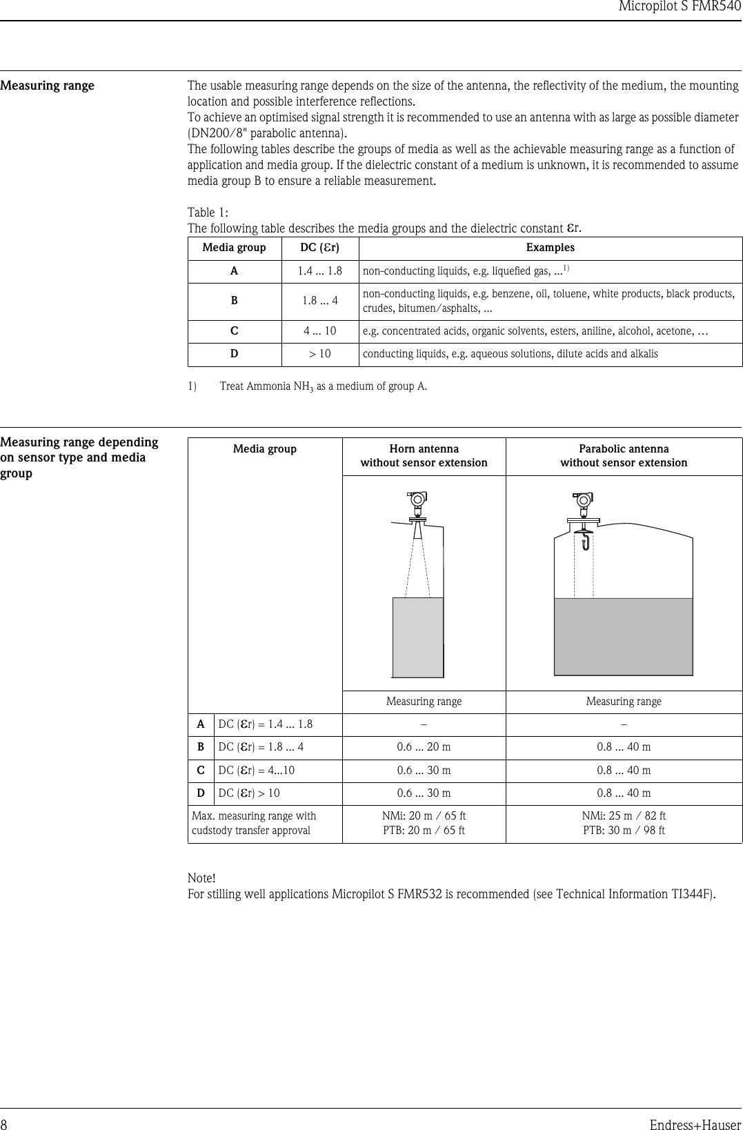
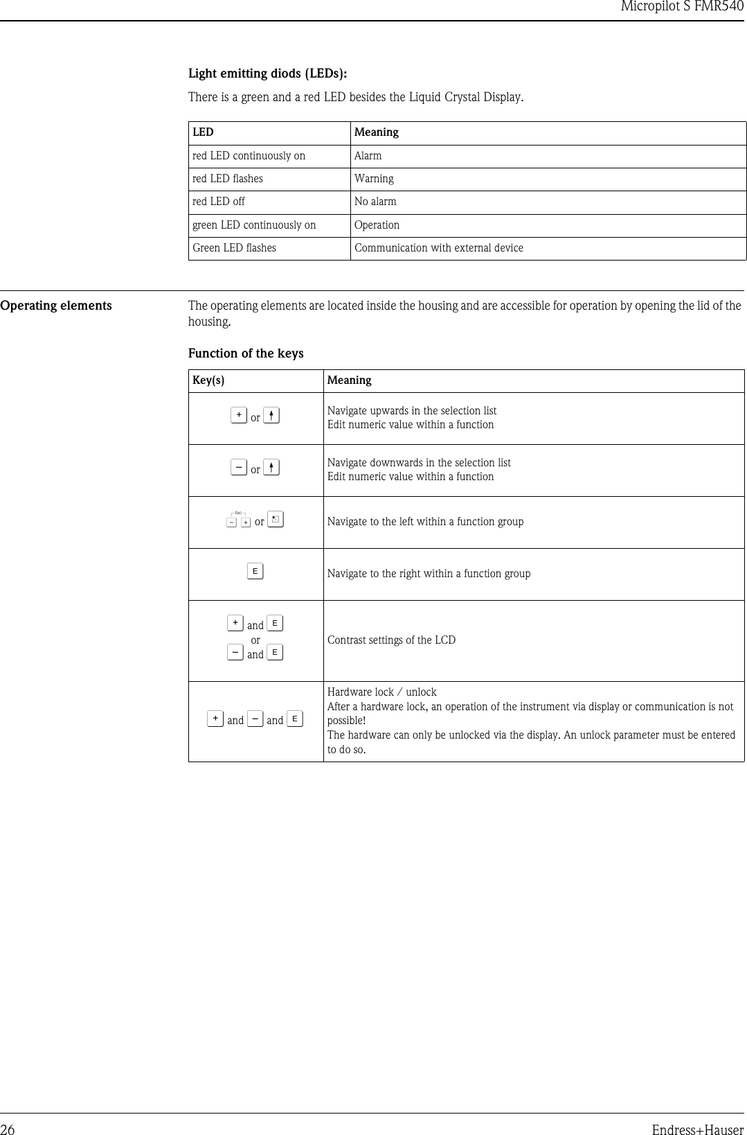
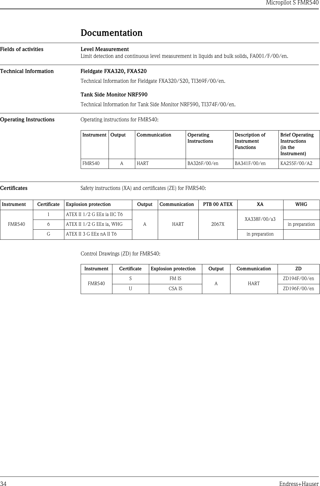
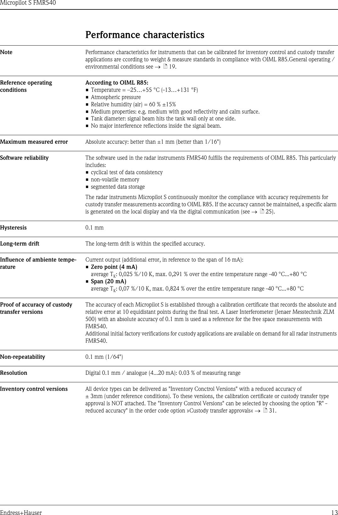
![Micropilot S FMR540Endress+Hauser 9Measuring conditions • The measuring range begins, where the beam hits the tank bottom. Particularly with dish bottoms or conical outlets the level cannot be detected below this point.• In case of media with a low dielectric constant (groups A and B), the tank bottom can be visible through the medium at low levels (low height C). Reduced accuracy has to be expected in this range. If this is not acceptable, we recommend positioning the zero point at a distance C (see Fig.) above the tank bottom in these applications.• In principle it is possible to measure up to the tip of the antenna with FMR540. However, due to considerations regarding corrosion and build-up, the end of the measuring range should not be chosen any closer than A (see Fig.).•B requests the smallest possible measuring range (see fig.).• Tank diameter and height should be at least dimensioned such that a reflection of the radar signal on both sides of the tank can be avoided.• Depending on its consistence, foam can either absorb microwaves or reflect them off the foam surface. Measurement is possible under certain conditions.L00-FMR54xxx-17-00-00-yy-009Behaviour if measuring range is exceededThe behaviour in case of the measuring range being exceeded can be freely set: the default setting is a current of 22 mA and the generation of a digital warning (E651).Operating frequency • FMR540: 26 GHz ultra wideband systemA [m (inch)] B [m (inch)] C [mm (inch)]FMR540 (Horn Antenna without extension) 0.6 (23.6) > 0.5 (> 20) > 300 (> 12)FMR540 (parabolic Antenna without extension) 0.8 (31.5) > 0.5 (> 20) > 300 (> 12)100%0%BAC](https://usermanual.wiki/Endress-and-Hauser-and-Co/FMR09/User-Guide-1297123-Page-9.png)
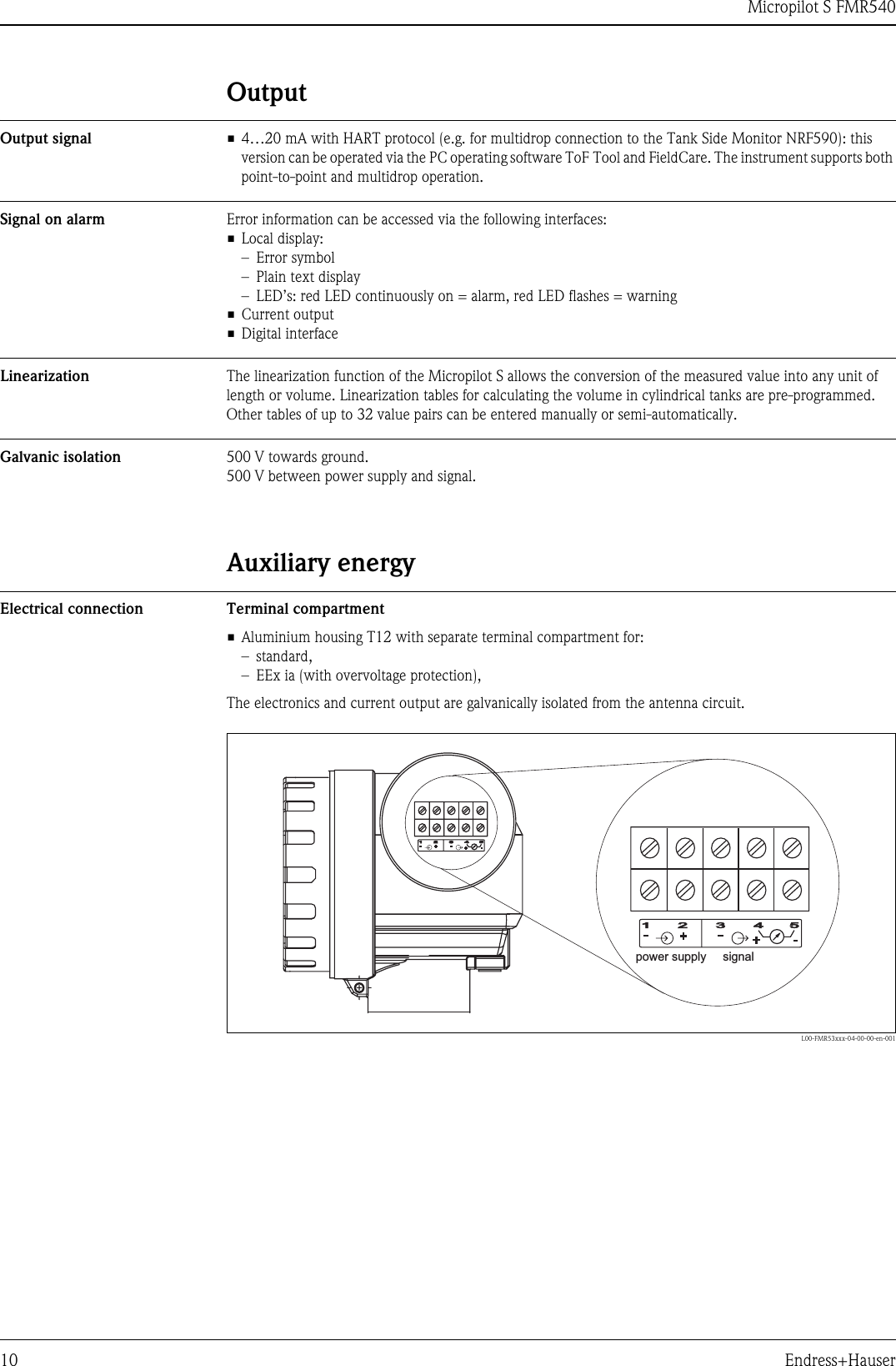
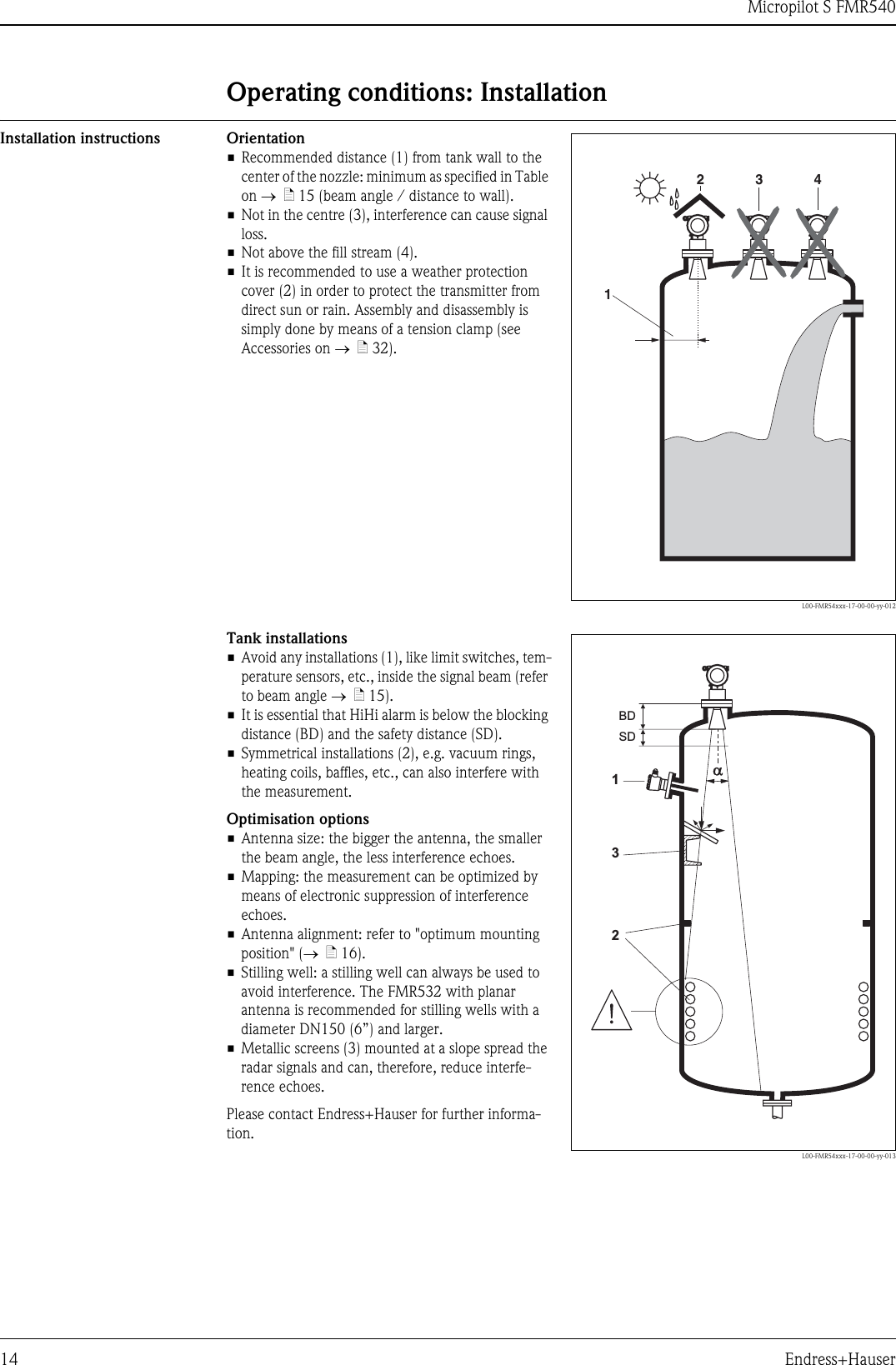
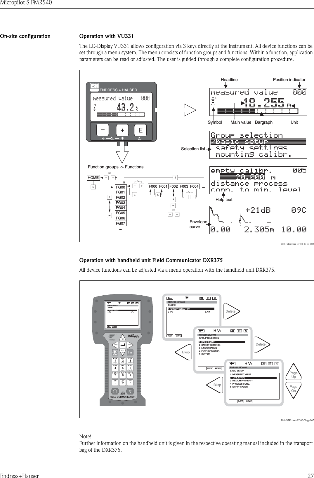
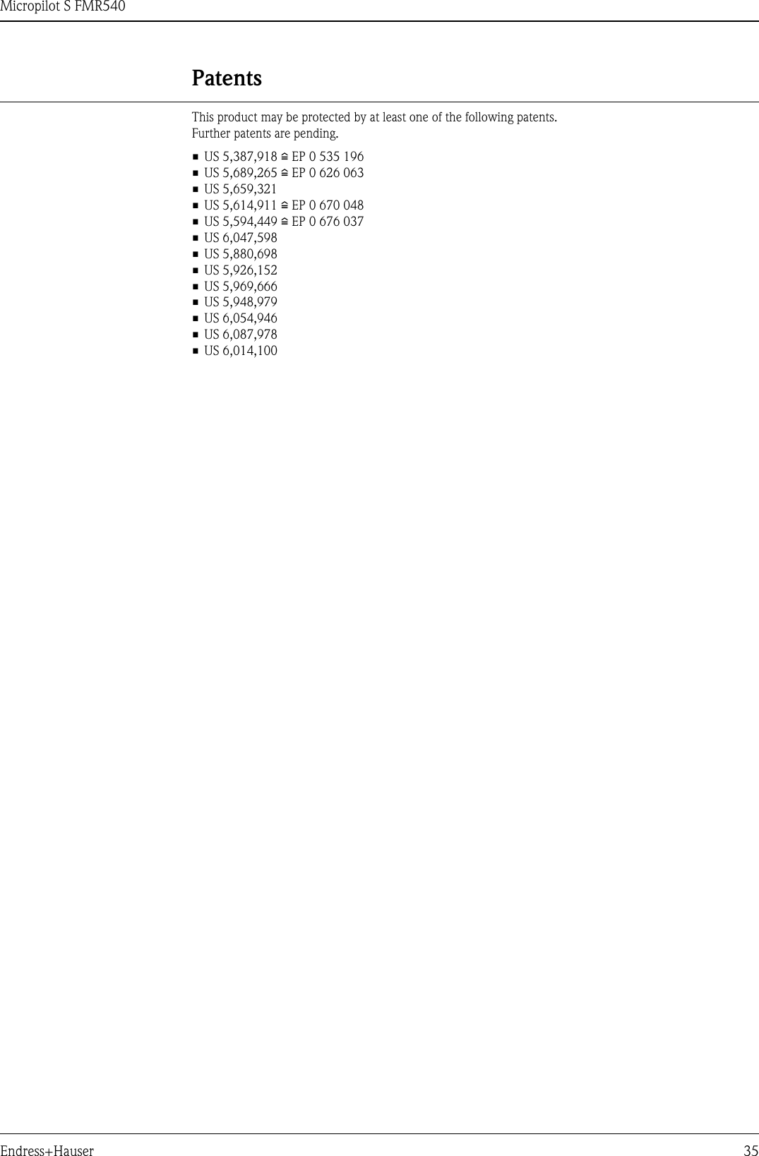
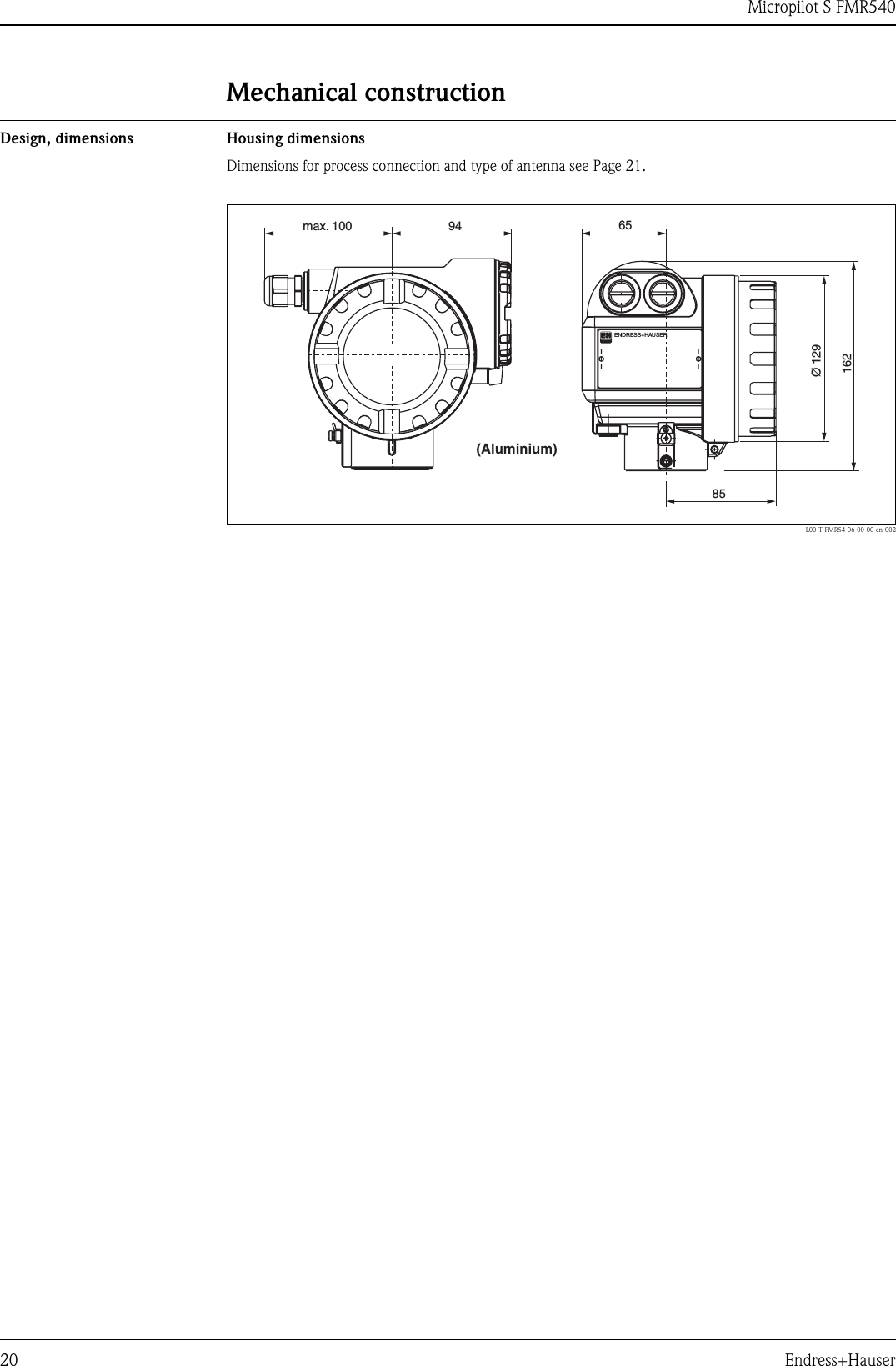
![Micropilot S FMR54016 Endress+HauserInstallation on tank FMR540 Optimum mounting positionL00-FMR54xxx-17-00-00-en-01090°90°Maker if usingANSI, DIN orJIS flangesMarker if usingEndress+Hauser UNI flangeTurn housingallen key4 mm/0.1”The housing can be turned inorder to simplify access to the displayand the terminal compartmentStandard installation FMR540 with horn antenna• Observe installation instructions on Page 14.• Marker is aligned towards tank wall.• The marker is always exactly in the middle between two bolt-holes in the flange.• After mounting, the housing can be turned 350° in order to simplify access to the display and the terminal compartment.• Adjust vertical sensor alignment in case the flange is not parallel to the face is medium surface.• The horn antenna should protrude from the nozzle. If necessary, choose version with antenna extension (→ä21).Note!Please contact Endress+Hauser for application with higher nozzle.• The horn antenna should be installed with 1 degree inclination towards the tank center.To avoid interference reflections or for optimum alignment within the tank, the FMR540 with optional top target positioner can be swiveled by 15° in all directions. For more informations please see instructions in KA274F/00.Please contact Endress+Hauser Service Organisation for commisioning.L00-FMR250xx-17-00-00-en-004HØDAntenna size 100 mm / 4"D [mm / inch] 95 / 3.7H [mm / inch](without antenna extension) < 430 / < 19.2](https://usermanual.wiki/Endress-and-Hauser-and-Co/FMR09/User-Guide-1297123-Page-16.png)
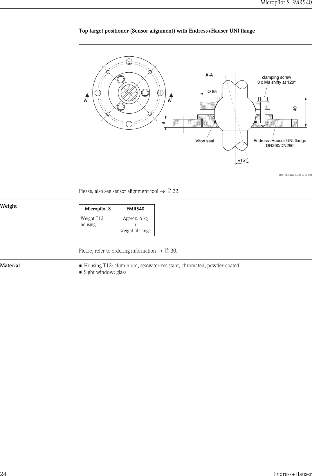
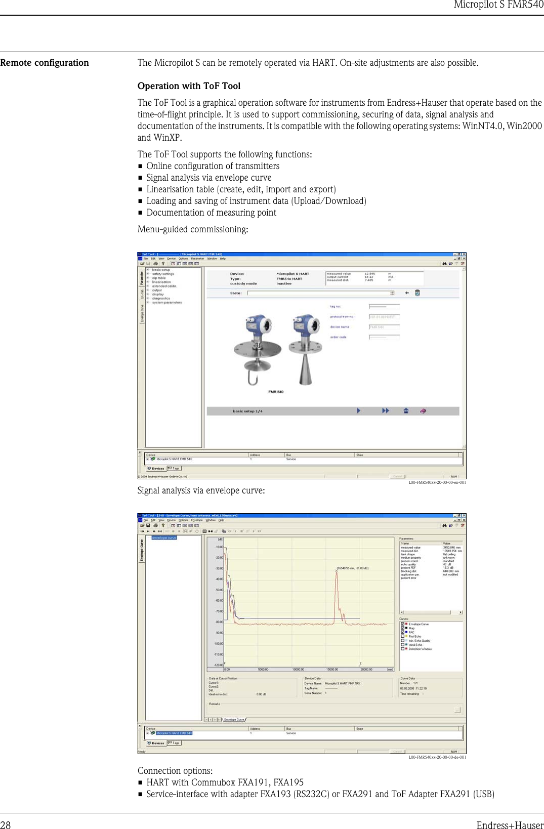
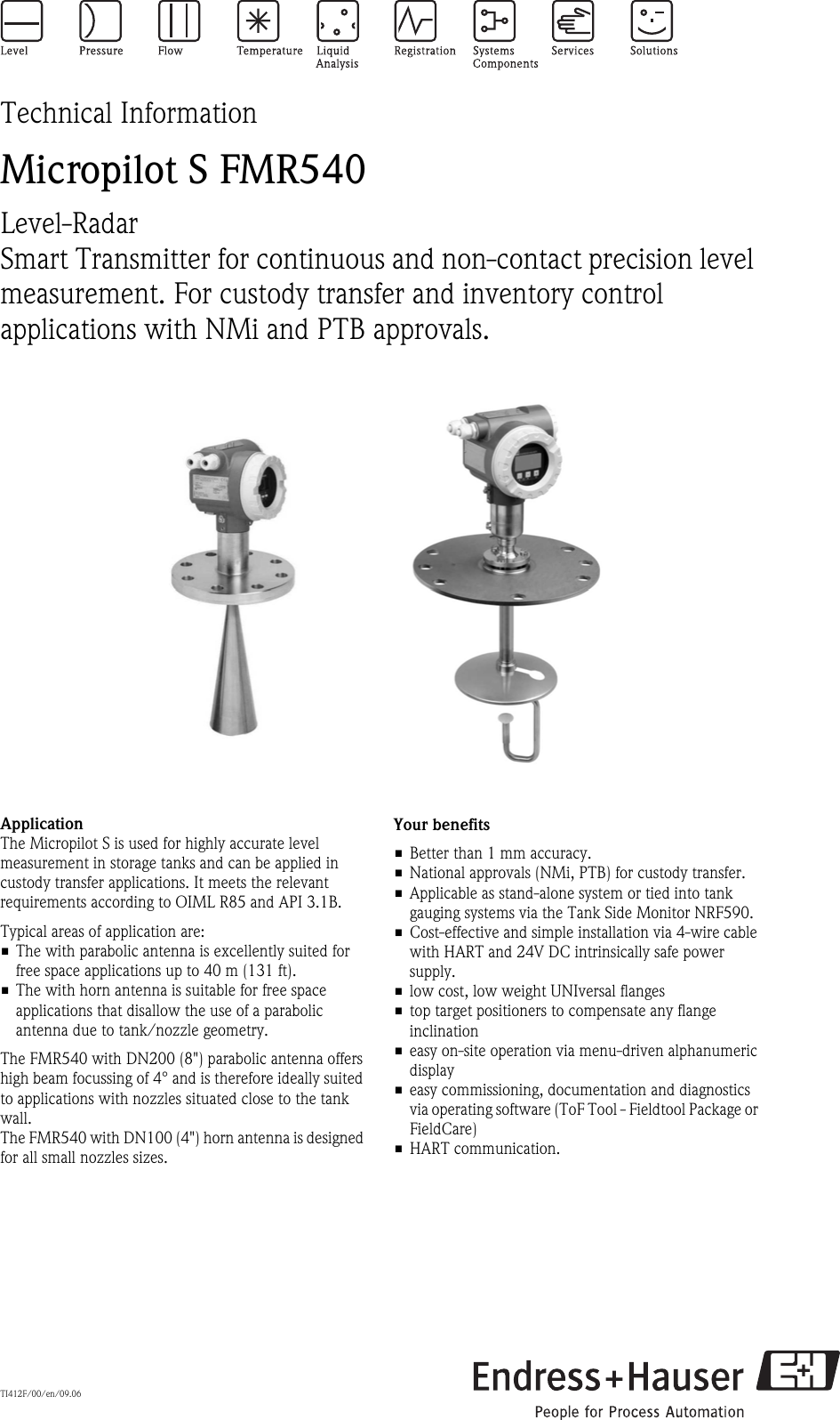
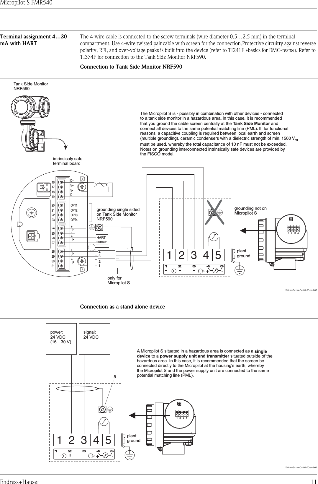
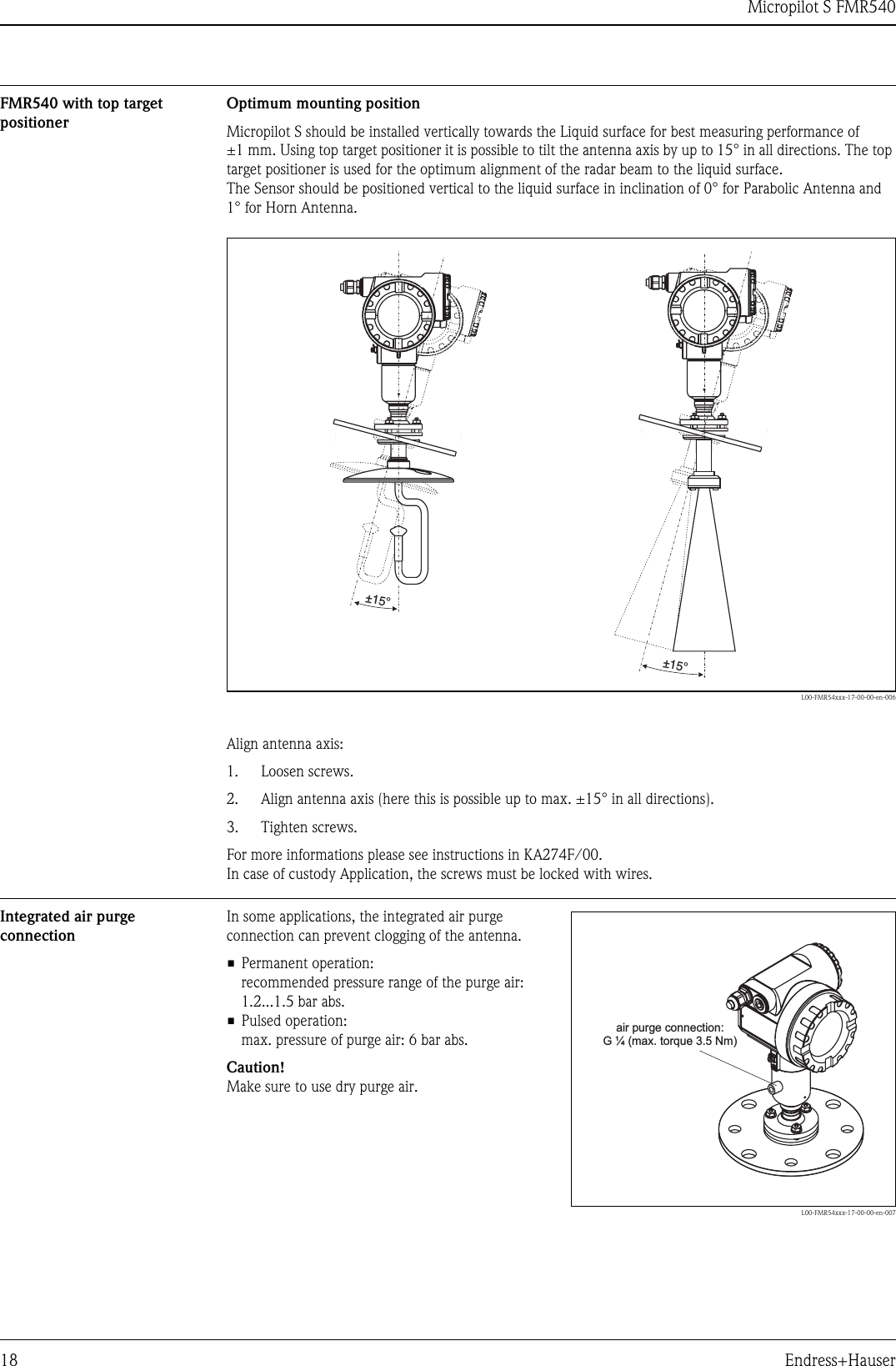
![Micropilot S FMR540Endress+Hauser 17Standard installation FMR540 with parabolic antenna• Observe installation instructions on Page 14.• Marker is aligned towards tank wall.• The marker is always exactly in the middle between two bolt-holes in the flange.• After mounting, the housing can be turned 350° in order to simplify access to the display and the terminal compartment.• Ideally the parabolic antenna should protrude from the nozzle (1). If necessary, choose version with antenna extension (→ä21).Particularly when using the top target positioner, please ensure that the parabolic reflector is protruding from the nozzle/roof so as not to inhibit alignment.Note!For application with higher nozzle install parabolic antenna completely in the nozzle (2), including RF-wave guide (3).• The parabolic antenna should be installed vertically.To avoid interference reflections or for optimum alignment within the tank, the FMR540 with optional top target positioner can be swiveled by 15° in all directions. For more informations please see instructions in KA274F/00. Please, contact Endress+Hauser Service organization for commissioning.L00-FMR54xxx-17-00-00-en-004HØD123Antenna size 200 mm / 8"D [mm / inch] 197 / 7.75H [mm / inch] (without antenna extension) < 50 / < 1.96](https://usermanual.wiki/Endress-and-Hauser-and-Co/FMR09/User-Guide-1297123-Page-17.png)
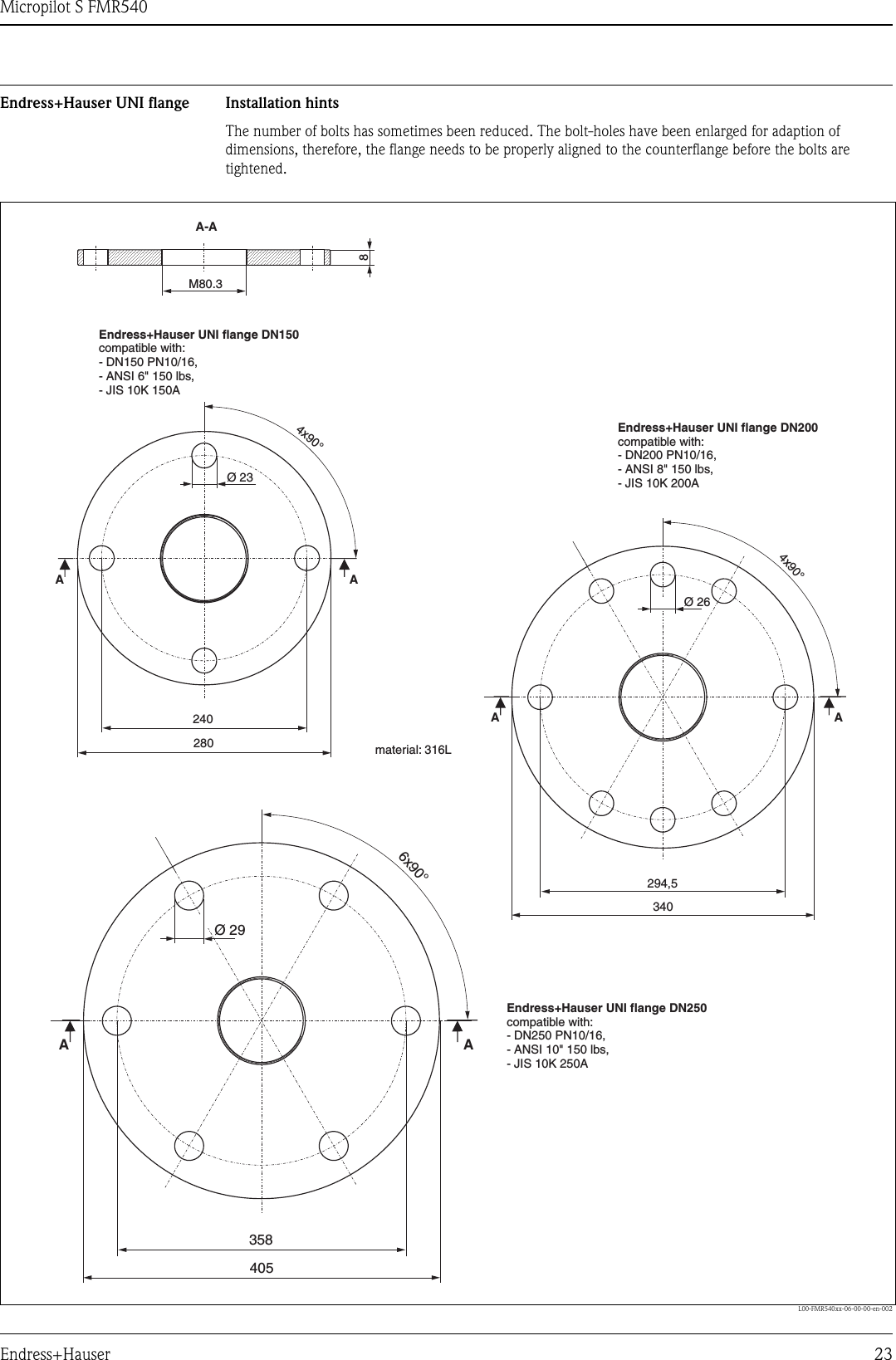
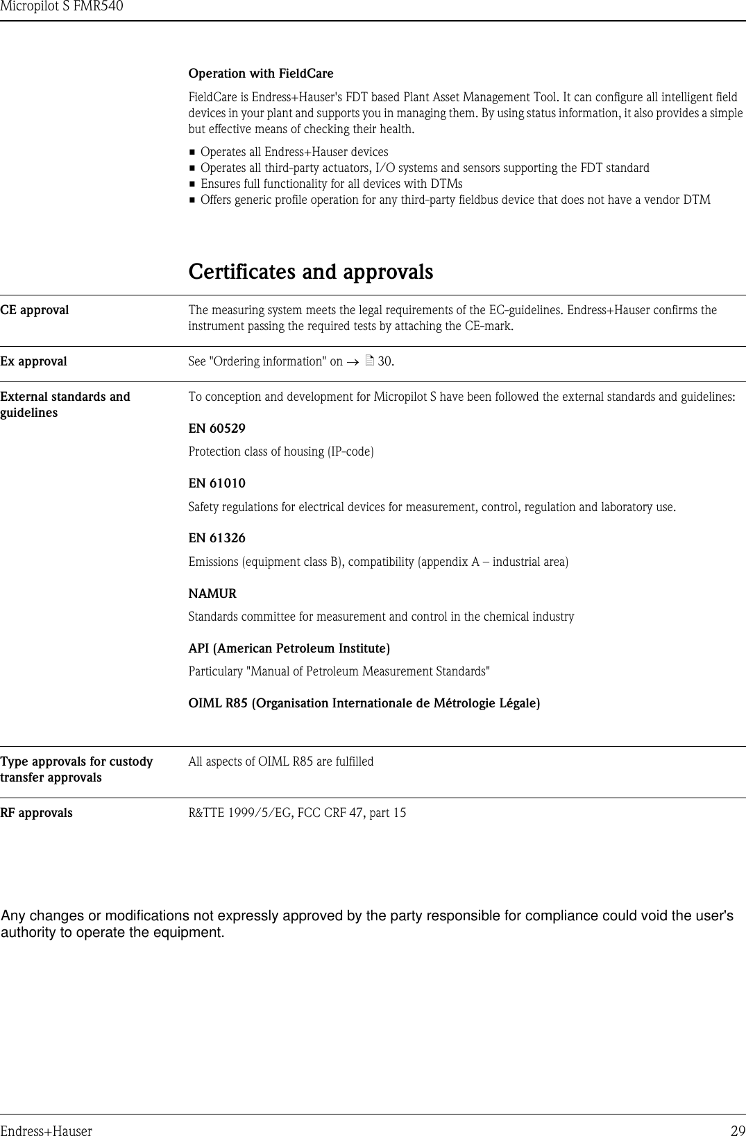
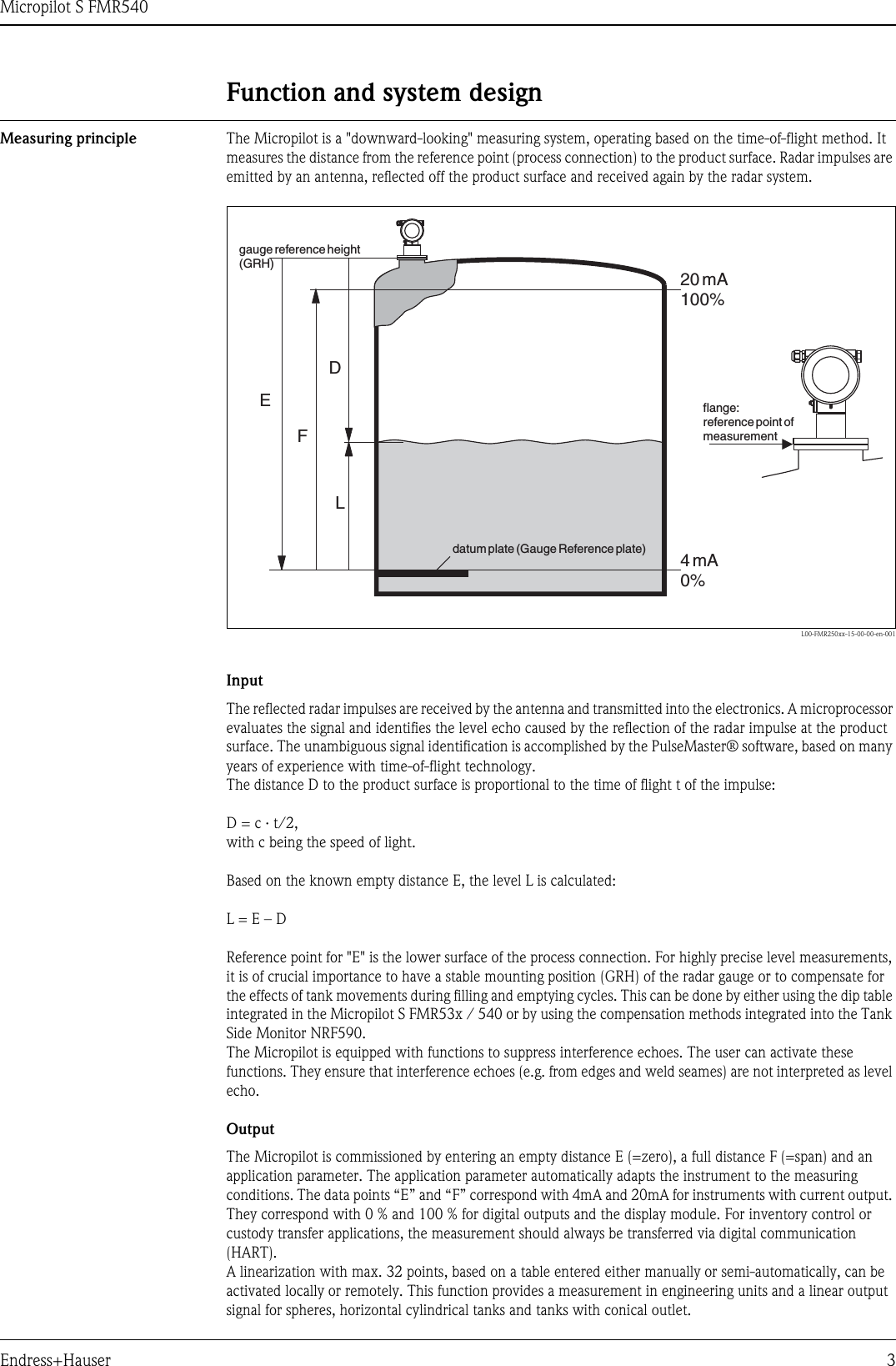
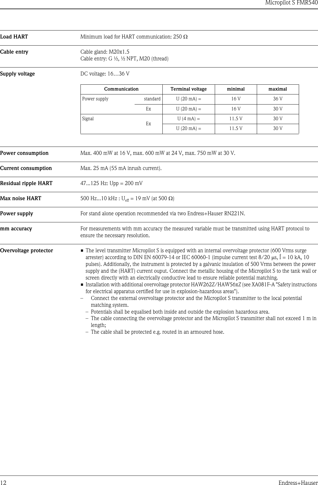
![Micropilot S FMR540Endress+Hauser 21Micropilot M FMR540 - process connection, type of antennaHousing dimensions →ä20.L00-FMR540xx-06-00-00-en-001LLLL5050135401351355050ØdØdØd150/250/450150/250/450200mm/8”95 197430 195100mm/4”b [mm] b [mm]b [mm]L [mm] L [mm]d [mm] d [mm]D [mm] D [mm]D [mm]220 285 210 280228.6 279.420 22 18 2223.9 25.4DN 100 DN 150 DN 100 DN 1504” 6”ØDØ 280 (DN 150)ØØ 405 (DN 250)340 (DN 200)b88Ø60Ø60Ø60ØdParabolic antennaHorn antennafor 10KFlangeFlange to JIS B2220for 150 lbsFlangeFlange to ASME B16.5for PN10/16Antenna size Antenna sizeHorn antenna Parabolic antennaFlangeFlange to EN 1092-1 (agreeable to DIN 2527)T12 housingFlange DN100…150or equivalentTop Taget Positioner(Sensor Alignment) withEndress+Hauser UNI flange DN 200/250Endress+Hauser UNI flangeDN 150DN 200DN 250Ø 280 (DN 150)Ø 340 (DN 200)Ø 405 (DN 250)](https://usermanual.wiki/Endress-and-Hauser-and-Co/FMR09/User-Guide-1297123-Page-21.png)