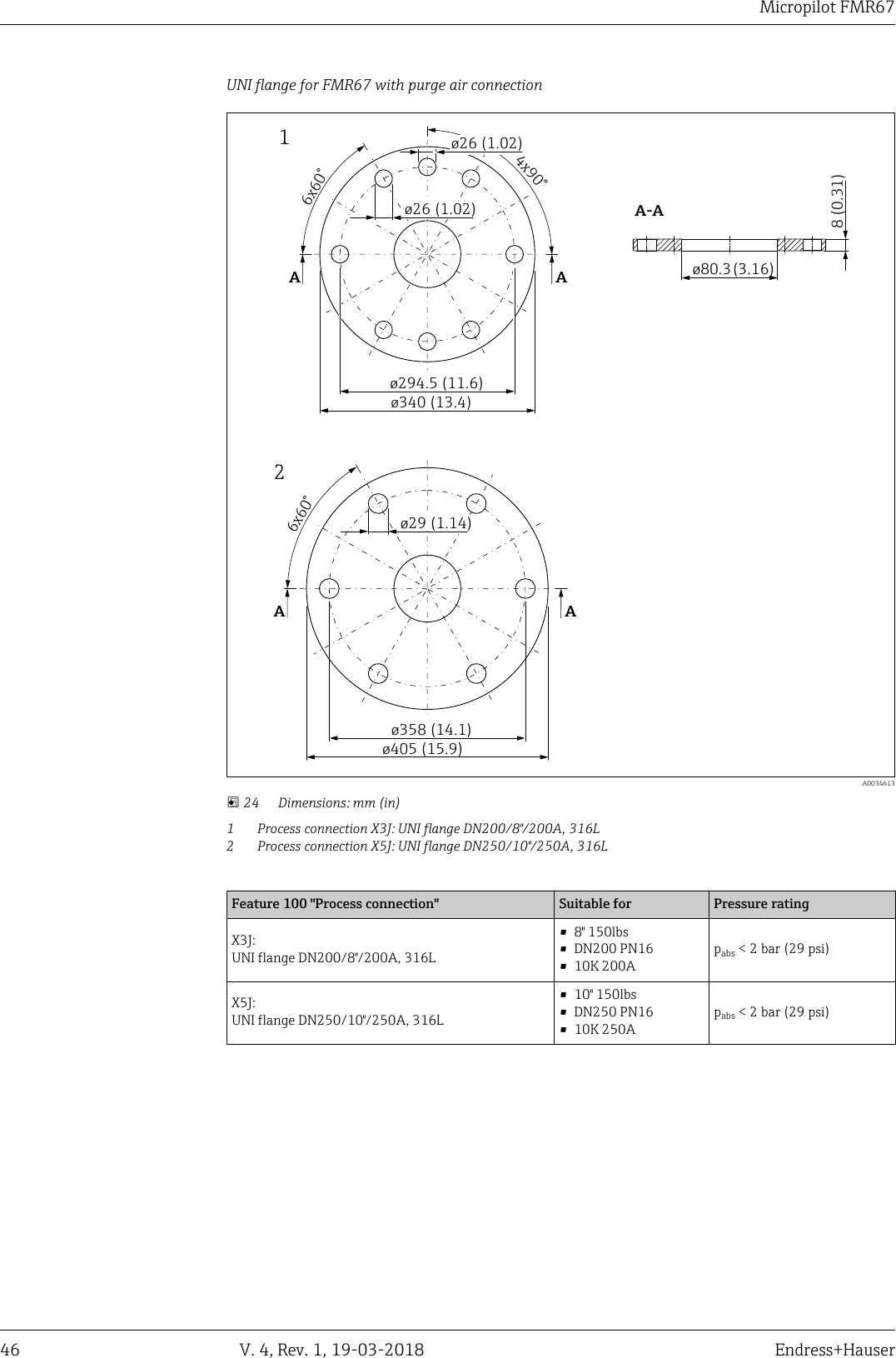
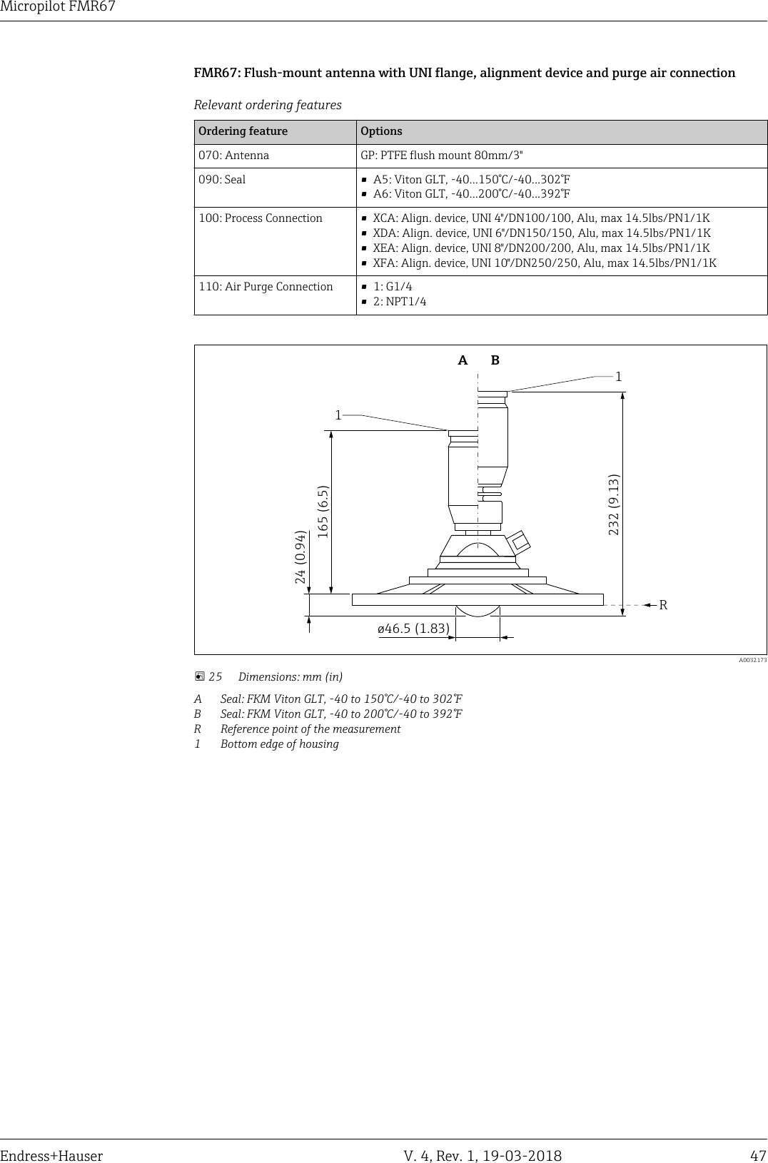
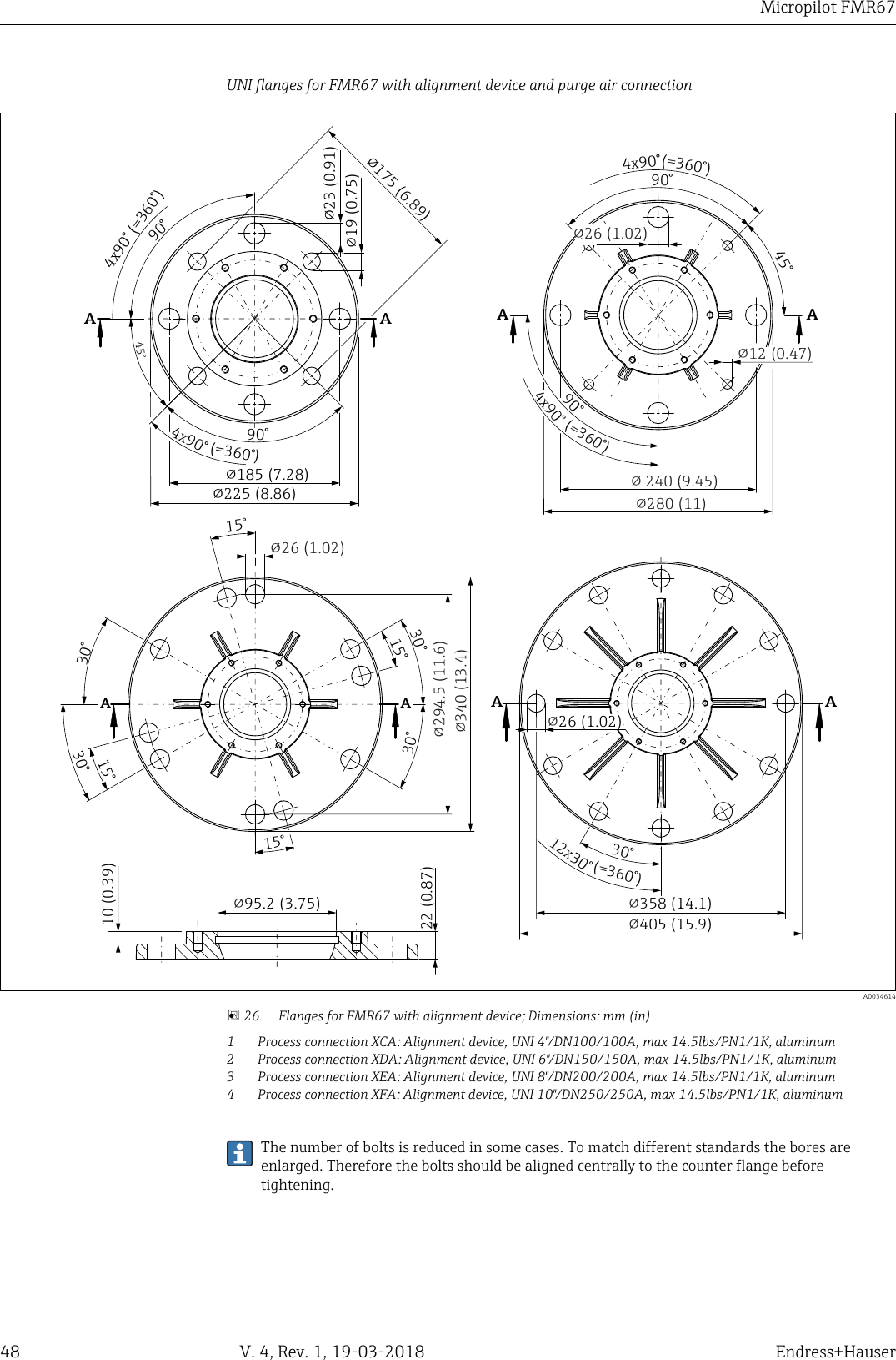
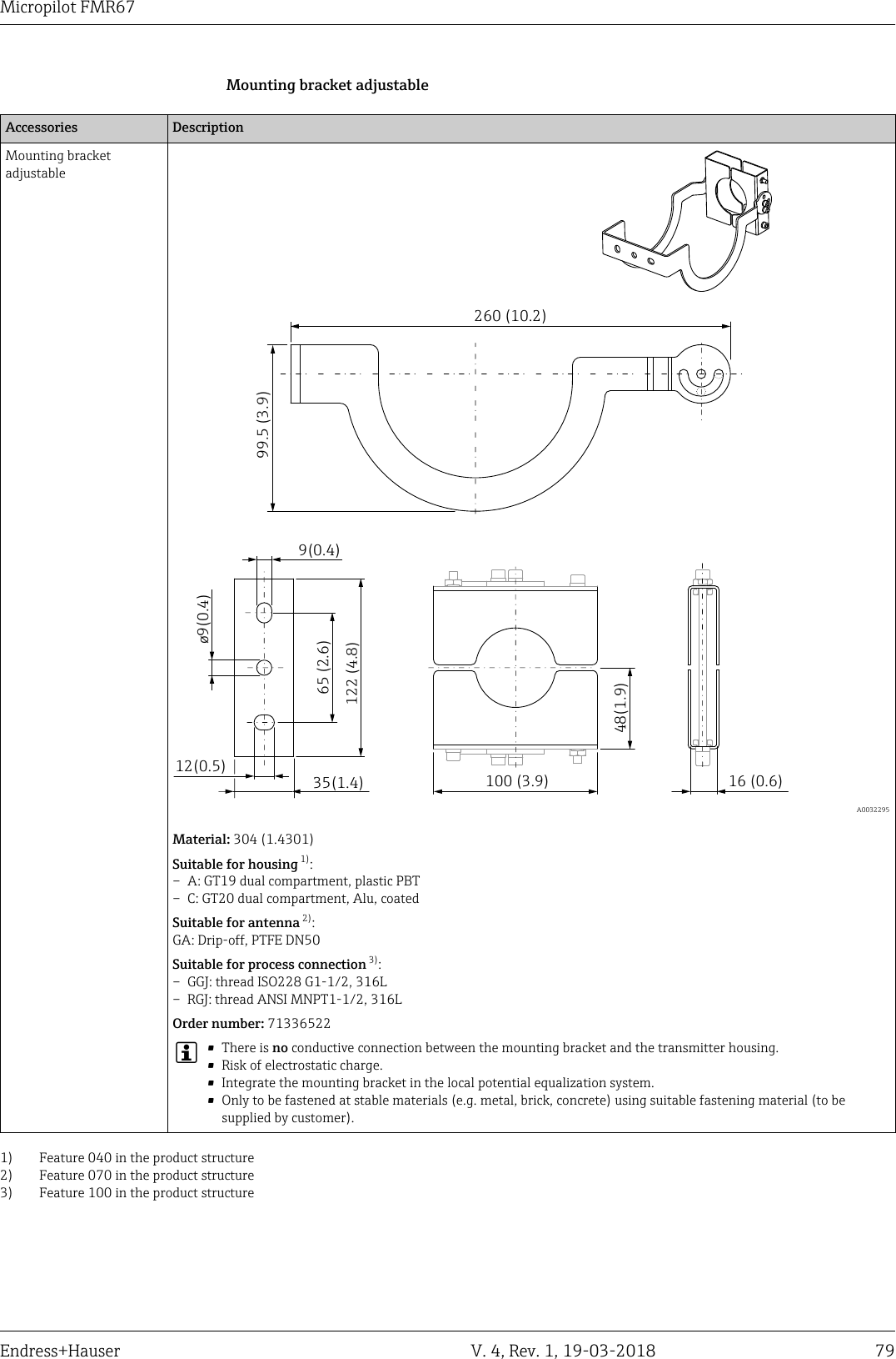
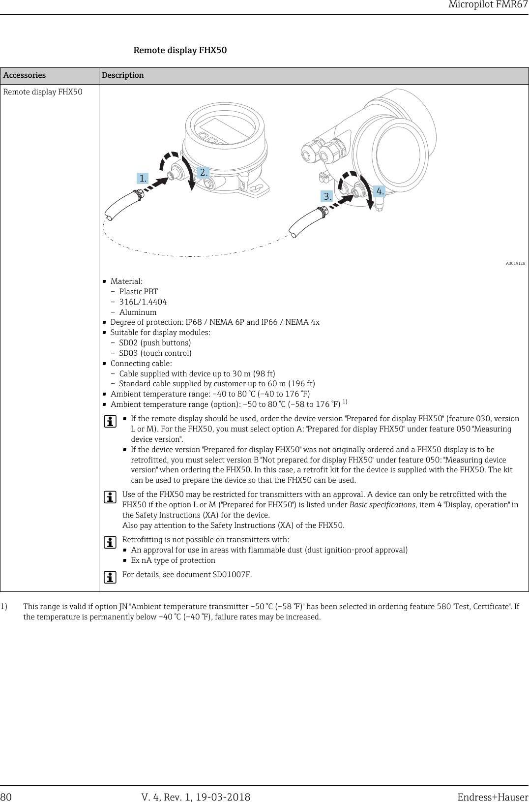
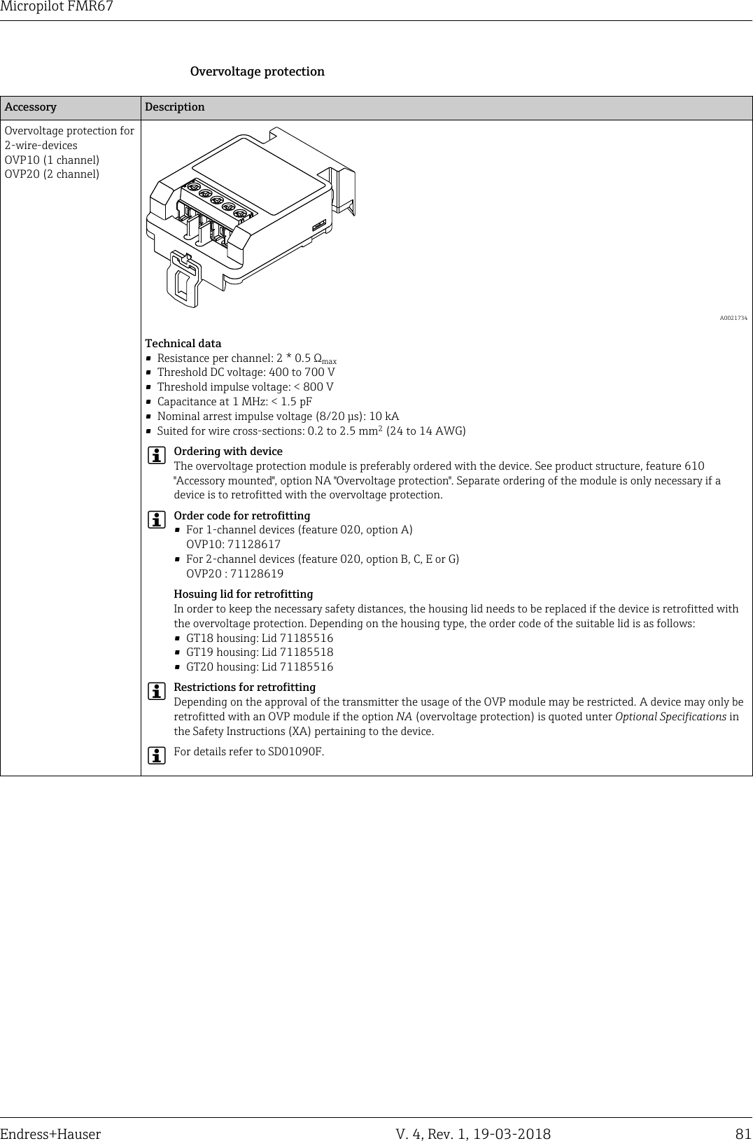
Endress and Hauser and Co FMR6XEL Level Probing Radar User Manual Micropilot FMR67

Endress and Hauser GmbH and Co Level Probing Radar Micropilot FMR67

Contents

User Manual 3

DRAFT DRAFT   DRAFT   DRAFT   DRAFT   DRAFT   DRAFTDRAFT   DRAFT   DRAFTFüllstandmessung in SchüttgüternApplication• Continuous, non-contact level measurement of bulk solidsranging from powdery to lumpy• PTFE drip-off antenna or PTFE-plated, flush-mounted antenna• Maximum measuring range: 125 m (410 ft)• Temperature: –40 to +200 °C (–40 to +392 °F)• Pressure: –1 to +16 bar (–14.5 to +232 psi)• Accuracy: ± 3 mm (0.12 in)• Linearity protocol (3-point, 5-point)Your benefits• Innovative drip-off antenna made of PTFE• Reliable measurement thanks to improved focusing and small beam angle,particularly in silos with many internal fittings• Safety by design - ensures highest safety• Easy, guided commissioning with intuitive user interface•Bluetooth® wireless technology for commissioning, operation and maintenance viafree iOS / Android app SmartBlue• Maximum reliability thanks to multi-echo tracking• HistoROM configuration memory makes for easier commissioning,maintenance and diagnostics• Purge air connection for cleaning in extreme conditions• Alignment device for easy adaptation of sensor• SIL2 as per IEC 61508, SIL3 for homogeneous or diverse redundancy• Easy proof testing for SIL• RFID TAG - easy identification of measuring points for improved data access• Heartbeat TechnologyProducts Solutions ServicesTechnical InformationMicropilot FMR67Freistrahlendes RadarTI01304F/00/EN/04.1871394735
DRAFT DRAFT   DRAFT   DRAFT   DRAFT   DRAFT   DRAFTDRAFT   DRAFT   DRAFTMicropilot FMR672 V. 4, Rev. 1, 19-03-2018 Endress+HauserTable of contentsImportant document information ............... 4Safety symbols ............................... 4Electrical symbols ............................. 4Symbols for certain types of information .............. 4Symbols in graphics ............................ 4Symbols at the device ........................... 5Terms and abbreviations ..................... 6Registered trademarks ....................... 7Function and system design ................... 8Measuring principle ............................ 8Input ..................................... 9Measured variable ............................. 9Measuring range .............................. 9Operating frequency ........................... 9Transmission power ............................ 9Output .................................. 10Output signal ............................... 10Signal on alarm .............................. 11Linearization ............................... 11Galvanic isolation ............................ 11Protocol-specific data .......................... 11Power supply ............................. 13Terminal assignment .......................... 13Device plug connectors ......................... 17Supply voltage .............................. 18Power consumption ........................... 19Current consumption .......................... 19Power supply failure .......................... 19Potential equalization ......................... 19Cable entries  ............................... 20Cable specification ............................ 20Overvoltage protection ......................... 20Performance characteristics .................. 21Reference operating conditions ................... 21Reference accuracy ........................... 21Measured value resolution ...................... 21Response time .............................. 22Influence of ambient temperature ................. 22Installation ............................... 23Installation conditions ......................... 23Installation: Drip-off antenna PTFE 50 mm / 2" ......... 28Installation: flush mount antenna .................. 29Purge air connection for FMR67 ................... 30Container with heat insulation .................... 31Environment .............................. 32Ambient temperature range ..................... 32Ambient temperature limits ..................... 32Storage temperature .......................... 33Climate class ............................... 33Altitude according to IEC61010-1 Ed.3 .............. 34Degree of protection .......................... 34Vibration resistance ........................... 34Electromagnetic compatibility (EMC) ............... 34Process .................................. 35Process temperature, process pressure ............... 35Dielectric constant ............................ 37Mechanical construction .................... 38Dimensions ................................ 38Weight ................................... 49Materials: GT18 housing (stainless steel, corrosion-resistant) .................................. 50Materials: GT19 housing (plastic) .................. 51Materials: GT20 housing (die-cast aluminum, powder-coated) ................................... 52Materials: antenna and process connection ........... 53Materials: Weather protection cover ................ 55Operability ............................... 56Operating concept ............................ 56Local operation .............................. 57Operation with remote display and operating moduleFHX50 ................................... 57Operation via Bluetooth® wireless technology .......... 58Remote operation ............................ 58SupplyCare inventory management software .......... 60Certificates and approvals ................... 63CE mark ................................... 63RoHS ..................................... 63RCM-Tick marking ............................ 63Ex approval ................................ 63Dual seal according to ANSI/ISA 12.27.01 ............ 63Functional safety ............................. 63WHG ..................................... 63Pressure equipment with allowable pressure≤ 200 bar (2 900 psi) .......................... 63Marine approval ............................. 64Radio standard EN 302729-1/2 ................... 64Radio standard EN 302372-1/2 ................... 65FCC ...................................... 65Industry Canada ............................. 65CRN approval ............................... 65Test, certificate .............................. 67Hard-copy product documentation ................. 67Other standards and guidelines ................... 68Ordering information ....................... 69Ordering information .......................... 693-point linearity protocol ....................... 705-point linearity protocol ....................... 71Customer-specific configuration ................... 72Tagging (TAG) .............................. 72Services ................................... 72
DRAFT DRAFT   DRAFT   DRAFT   DRAFT   DRAFT   DRAFTDRAFT   DRAFT   DRAFTMicropilot FMR67Endress+Hauser V. 4, Rev. 1, 19-03-2018 3Application Packages ....................... 73Heartbeat Diagnostics ......................... 73Heartbeat Verification ......................... 74Heartbeat Monitoring ......................... 75Accessories ............................... 76Device-specific accessories ...................... 76Communication-specific accessories ................ 82Service-specific accessories ...................... 83System components ........................... 83Supplementary documentation ............... 84Standard documentation ........................ 84Safety Instructions (XA) ........................ 84
DRAFT DRAFT   DRAFT   DRAFT   DRAFT   DRAFT   DRAFTDRAFT   DRAFT   DRAFTMicropilot FMR674 V. 4, Rev. 1, 19-03-2018 Endress+HauserImportant document informationSafety symbols Symbol MeaningDANGERDANGER!This symbol alerts you to a dangerous situation. Failure to avoid this situation willresult in serious or fatal injury.WARNINGWARNING!This symbol alerts you to a dangerous situation. Failure to avoid this situation canresult in serious or fatal injury.CAUTIONCAUTION!This symbol alerts you to a dangerous situation. Failure to avoid this situation canresult in minor or medium injury.NOTICENOTE!This symbol contains information on procedures and other facts which do not result inpersonal injury.Electrical symbols Symbol MeaningDirect currentAlternating currentDirect current and alternating currentGround connectionA grounded terminal which, as far as the operator is concerned, is grounded via agrounding system.Protective Earth (PE)A terminal which must be connected to ground prior to establishing any otherconnections.The ground terminals are situated inside and outside the device:• Inner ground terminal: Connects the protectiv earth to the mains supply.• Outer ground terminal: Connects the device to the plant grounding system.Symbols forcertain types of information Symbol MeaningPermittedProcedures, processes or actions that are permitted.PreferredProcedures, processes or actions that are preferred.ForbiddenProcedures, processes or actions that are forbidden.TipIndicates additional information.Reference to documentation.AReference to page.Reference to graphic.Visual inspection.Symbols in graphics Symbol Meaning1, 2, 3 ... Item numbers1., 2., 3.… Series of stepsA, B, C, ... Views
DRAFT DRAFT   DRAFT   DRAFT   DRAFT   DRAFT   DRAFTDRAFT   DRAFT   DRAFTMicropilot FMR67Endress+Hauser V. 4, Rev. 1, 19-03-2018 5Symbol MeaningA-A, B-B, C-C, ... Sections-Hazardous areaIndicates a hazardous area..Safe area (non-hazardous area)Indicates the non-hazardous area.Symbols at the device Symbol MeaningSafety instructionsObserve the safety instructions contained in the associated Operating Instructions.Temperature resistance of the connection cablesSpecifies the minimum value of the temperature resistance of the connection cables.
DRAFT DRAFT   DRAFT   DRAFT   DRAFT   DRAFT   DRAFTDRAFT   DRAFT   DRAFTMicropilot FMR676 V. 4, Rev. 1, 19-03-2018 Endress+HauserTerms and abbreviationsTerm/abbreviation ExplanationBA Document type "Operating Instructions"KA Document type "Brief Operating Instructions"TI Document type "Technical Information"SD Document type "Special Documentation"XA Document type "Safety Instructions"PN Nominal pressureMWP Maximum Working PressureThe MWP can also be found on the nameplate.ToF Time of FlightFieldCare Scalable software tool for device configuration and integrated plant asset managementsolutionsDeviceCare Universal configuration software for Endress+Hauser HART, PROFIBUS,FOUNDATION Fieldbus and Ethernet field devicesDTM Device Type ManagerDD Device Description for HART communication protocolDC Relative dielectric constant εrOperating tool The term "operating tool" is used in place of the following operating software:FieldCare / DeviceCare, for operation via HART communication and PCBD Blocking Distance; no signals are analyzed within the BD.
DRAFT DRAFT   DRAFT   DRAFT   DRAFT   DRAFT   DRAFTDRAFT   DRAFT   DRAFTMicropilot FMR67Endress+Hauser V. 4, Rev. 1, 19-03-2018 7Registered trademarksHART®Registered trademark of the HART Communication Foundation, Austin, USABluetooth®The Bluetooth® word mark and logos are registered trademarks owned by the Bluetooth SIG, Inc. andany use of such marks by Endress+Hauser is under license. Other trademarks and trade names arethose of their respective owners.Apple®Apple, the Apple logo, iPhone, and iPod touch are trademarks of Apple Inc., registered in the U.S.andother countries. App Store is a service mark of Apple Inc.Android®Android, Google Play and the Google Play logo are trademarks of Google Inc.KALREZ®, VITON®Registered trademark of DuPont Performance Elastomers L.L.C., Wilmington, USATEFLON®Registered trademark of E.I. DuPont de Nemours & Co., Wilmington, USA
DRAFT DRAFT   DRAFT   DRAFT   DRAFT   DRAFT   DRAFTDRAFT   DRAFT   DRAFTMicropilot FMR678 V. 4, Rev. 1, 19-03-2018 Endress+HauserFunction and system designMeasuring principle The Micropilot is a "downward-looking" measuring system, operating based on the frequencymodulated continuous wave method (FMCW). The antenna emits an electromagnetic wave at acontinuously varying frequency. This wave is reflected by the product and received again by theantenna.DR  A0032017 1 FMCW principle: transmission and reflection of the continuous waveR Reference point of measurementD Distance between reference point and product surfaceThe frequency of this wave is modulated in the form of a sawtooth signal between two limitfrequencies f1 and f2:ft12f2f1∆t ∆f  A0023771 2 FMCW principle: result of frequency modulation1 Transmitted signal2 Received signalThis results in the following difference frequency at any time between the transmitted signal and thereceived signal:Δf = k Δtwhere Δt is the run time and k is the specified increase in frequency modulation.Δt is given by the distance D between the reference point R and the product surface:D = (c Δt) / 2where c is the speed of propagation of the wave.In summary, D can be calculated from the measured difference frequency Δf. D is then used todetermine the content of the tank or silo.
DRAFT DRAFT   DRAFT   DRAFT   DRAFT   DRAFT   DRAFTDRAFT   DRAFT   DRAFTMicropilot FMR67Endress+Hauser V. 4, Rev. 1, 19-03-2018 9InputMeasured variable The measured variable is the distance between the reference point and the product surface. The levelis calculated based on "E", the empty distance entered. Optionally, the level can be converted to othervariables (volume, mass) by linearization (32 value pairs).Measuring range Maximum measuring rangeDevice Antenna 1) Maximum measuring rangeFMR67 GA:Drip-off, PTFE 50 mm / 2"50 m (164 ft)GP:PTFE flush mount 80 mm / 3"125 m (410 ft)1) Feature 070 in the product structureUsable measuring rangeThe usable measuring range depends on the antenna size, the medium's reflective properties, theinstallation position and any possible interference reflections.Operating frequency Approx. 80 GHzUp to 8 devices can be installed in the same tank without interfering with each other.Transmission power • Peak power: 6.3 mW• Average output power: 63 µW
DRAFT DRAFT   DRAFT   DRAFT   DRAFT   DRAFT   DRAFTDRAFT   DRAFT   DRAFTMicropilot FMR6710 V. 4, Rev. 1, 19-03-2018 Endress+HauserOutputOutput signal HARTSignal coding FSK ±0.5 mA over current signalData transmission rate 1 200 Bit/sGalvanic isolation YesBluetooth® wireless technologyDevice version Ordering feature 610 "Accessory mounted", option NF "Bluetooth"Operation / configuration By the SmartBlue app.Range under reference conditions > 10 m (33 ft)Encryption Encrypted communication and password encryption prevent incorrectoperation by unauthorized persons.Switch outputFor HART devices, the switch output is available as an option. See product structure, feature 20:"Power Supply, Output", option B: "2-wire; 4-20mA HART, switch output"Switch outputFunction Open collector switching outputSwitching behavior Binary (conductive or non-conductive), switches when the programmable switchpoint is reachedFailure mode non-conductiveElectrical connection values U = 16 to 35  VDC, I = 0 to 40  mAInternal resistance RI < 880 ΩThe voltage drop at this internal resistance has to be taken into account onplanning the configuration. For example, the resulting voltage at a connectedrelay must be sufficient to switch the relay.Insulation voltage floating, Insulation voltage 1 350  VDC to power supply aund 500  VAC to groundSwitch point freely programmable, separately for switch-on and switch-off pointSwitching delay freely programmable from 0 to 100 s, separately for switch-on and switch-offpointNumber of switching cycles corresponds to the measuring cycleSignal sourcedevice variables• Level linearized• Distance• Terminal voltage• Electronic temperature• Relative echo amplitude• Diagnostic values, Advanced diagnosticsNumber of switching cycles unlimited
DRAFT DRAFT   DRAFT   DRAFT   DRAFT   DRAFT   DRAFTDRAFT   DRAFT   DRAFTMicropilot FMR67Endress+Hauser V. 4, Rev. 1, 19-03-2018 11Signal on alarm Depending on the interface, failure information is displayed as follows:• Current output (for HART devices)– Failsafe mode selectable (in accordance with NAMUR Recommendation NE 43):Minimum alarm: 3.6 mAMaximum alarm (= factory setting): 22 mA– Failsafe mode with user-selectable value: 3.59 to 22.5 mA• Local display– Status signal (in accordance with NAMUR Recommendation NE 107)– Plain text display• Operating tool via HART communication or service interface (CDI)– Status signal (in accordance with NAMUR Recommendation NE 107)– Plain text displayLinearization The linearization function of the device allows the conversion of the measured value into any unit oflength or volume. Linearization tables for calculating the volume in cylindrical tanks are pre-programmed. Other linearization tables of up to 32 value pairs can be entered manually or semi-automatically.Galvanic isolation All circuits for the outputs are galvanically isolated from each other.Protocol-specific data HARTManufacturer ID 17 (0x11)Device type ID 0x112BHART specification 7.0Device description files (DTM, DD) Information and files under:•www.endress.com•www.fieldcommgroup.orgHART load min. 250 ΩHART device variables The measured values can be freely assigned to the device variables.Measured values for PV (primary variable)• Level linearized• Distance• Electronic temperature• Relative echo amplitude• Area of incoupling• Analog output adv. diagnostics 1• Analog output adv. diagnostics 2Measured values for SV, TV, FV (second, third and fourth variable)• Level linearized• Distance• Electronic temperature• Terminal voltage• Relative echo amplitude• Absolute echo amplitude• Area of incoupling• Analog output adv. diagnostics 1• Analog output adv. diagnostics 2Supported functions • Burst mode• Additional transmitter statusWireless HART dataMinimum start-up voltage 16 VStart-up current 3.6 mAStart-up time 65 sMinimum operating voltage 14.0 V
DRAFT DRAFT   DRAFT   DRAFT   DRAFT   DRAFT   DRAFTDRAFT   DRAFT   DRAFTMicropilot FMR6712 V. 4, Rev. 1, 19-03-2018 Endress+HauserMultidrop current 4.0 mASet-up time 15 s
DRAFT DRAFT   DRAFT   DRAFT   DRAFT   DRAFT   DRAFTDRAFT   DRAFT   DRAFTMicropilot FMR67Endress+Hauser V. 4, Rev. 1, 19-03-2018 13Power supplyTerminal assignment 2-wire: 4-20mA HART1+24-20mA1-channel overvoltage protection-[16]A74...20 mA54123+–+–"1+24...20mAHART10 mmSpare part71108xxx2- wire level4-20 mA 4-20 mAHART[21]open-89#B+–4...20 mA54123+–6"  A0011294 3 Terminal assignment 2-wire; 4-20mA HARTA Without integrated overvoltage protectionB With integrated overvoltage protection1 Active barrier with power supply (e.g. RN221N): Observe terminal voltage2 HART communication resistor (≥ 250 Ω): Observe maximum load3 Connection for Commubox FXA195 or FieldXpert SFX350/SFX370 (via VIATOR Bluetooth modem)4 Analog display device: Observe maximum load5 Cable screen; observe cable specification6 4-20mA HART (passive): Terminals 1 and 27 Overvoltage protection module8 Terminal for potential equalization line9 Cable entry
DRAFT DRAFT   DRAFT   DRAFT   DRAFT   DRAFT   DRAFTDRAFT   DRAFT   DRAFTMicropilot FMR6714 V. 4, Rev. 1, 19-03-2018 Endress+Hauser2-wire: 4-20mA HART, switch output13++244-20mA/FIELDBUS4-20mA/2-channel overvoltage protection--[17]B10986!A1+24...20 mAHART10 mmSpare part71108xxx2- wire4-20 mA PFSHART[02/03]open-1+2-3+4-711++--233445514...20 mA≥250 Ω3+3+4-4-+–%4...20 mA≥250 Ω21+–%  A0013759 4 Terminal assignment 2-wire; 4-20mA HART, switch outputA Without integrated overvoltage protectionB With integrated overvoltage protection1 Active barrier with power supply (e.g. RN221N): Observe terminal voltage2 HART communication resistor (≥ 250 Ω): Observe maximum load3 Connection for Commubox FXA195 or FieldXpert SFX350/SFX370 (via VIATOR Bluetooth modem)4 Analog display device: Observe maximum load5 Cable screen; observe cable specification6 4-20mA HART (passive): Terminals 1 and 27 Switch output (open collector): Terminals 3 and 48 Terminal for potential equalization line9 Cable entry for 4-20mA HART line10 Cable entry for switch output line11 Overvoltage protection module
DRAFT DRAFT   DRAFT   DRAFT   DRAFT   DRAFT   DRAFTDRAFT   DRAFT   DRAFTMicropilot FMR67Endress+Hauser V. 4, Rev. 1, 19-03-2018 152-wire: 4-20mA HART, 4-20mAA13++244-20mA/FIELDBUS4-20mA/2-channel overvoltage protection--[17]141312!13++244...20mAHART4...20mA10 mmSpare part71108xxx2- wire level4-20 mA 4-20 mAHART[04/05]open--11++++----11223399558866774444+–+–4...20 mA4...20 mA10B4...20 mA4...20 mA####+–+–  A0013923 5 Terminal assignment 2-wire, 4-20 mA HART, 4...20mAA Without integrated overvoltage protectionB With integrated overvoltage protection1 Connection current output 22 Connection current output 13 Supply voltage for current output 1 (e.g. RN221N); Observe terminal voltage4 Cable screen; observe cable specification5 HART communication resistor (≥ 250 Ω): Observe maximum load6 Connection for Commubox FXA195 or FieldXpert SFX350/SFX370 (via VIATOR Bluetooth modem)7 Analog display device ; observe maximum load8 Analog display device ; observe maximum load9 Supply voltage for current output 2 (e.g. RN221N); Obeserve terminal voltage10 Overvoltage protection module11 Current output 2: Terminals 3 and 412 Terminal for the potential equalization line13 Cable entry for current output 114 Cable entry for current output 2This version is also suited for single-channel operation. In this case, current output 1 (terminals1 and 2) must be used.
DRAFT DRAFT   DRAFT   DRAFT   DRAFT   DRAFT   DRAFTDRAFT   DRAFT   DRAFTMicropilot FMR6716 V. 4, Rev. 1, 19-03-2018 Endress+HauserConnection examples for the switch outputFor HART devices, the switch output is available as an option. See product structure, feature 20:"Power Supply, Output", option B: "2-wire; 4-20mA HART, switch output"3++-4-Ri  A0015909 6 Connection of a relaySuitable relays (examples):• Solid-state relay: Phoenix Contact OV-24DC/480AC/5 with mountingrail connector UMK-1 OM-R/AMS• Electromechanical relay: Phoenix Contact PLC-RSC-12DC/213+ 21+4-Ri  A0015910 7 Connection of a digital input1 Pull-up resistor2 Digital inputFor optimum interference immunity we recommend to connect an external resistor (internalresistance of the relay or Pull-up resistor) of < 1 000 Ω.
DRAFT DRAFT   DRAFT   DRAFT   DRAFT   DRAFT   DRAFTDRAFT   DRAFT   DRAFTMicropilot FMR67Endress+Hauser V. 4, Rev. 1, 19-03-2018 17Device plug connectors For the versions with fieldbus plug connector (M12 or 7/8"), the signal line can be connectedwithout opening the housing.Pin assignment of the M12 plug connector2134  A0011175Pin Meaning1 Signal +2 not connected3 Signal -4 GroundPin assignment of the 7/8" plug connector4231  A0011176Pin Meaning1 Signal -2 Signal +3 Not connected4 Screen
DRAFT DRAFT   DRAFT   DRAFT   DRAFT   DRAFT   DRAFTDRAFT   DRAFT   DRAFTMicropilot FMR6718 V. 4, Rev. 1, 19-03-2018 Endress+HauserSupply voltage An external power supply is necessary.Various power supply units can be ordered as an accessory from Endress+Hauser.2-wire, 4-20mA HART, passive"Powersupply,output" 1)"Approval" 2) Terminalvoltage U atdeviceMaximum load R,depending on the supply voltageU0 of the power supply unitA:2-wire;4-20mAHART• Non-hazardous• Ex nA• Ex ic• CSA GP14 to 35 V 3)R [ ]WU0[V]10 14 2520 30 350500  A0031745Ex ia / IS 14 to 30 V 3)• Ex d(ia) /XP• Ex ic(ia)• Ex nA(ia)• Ex ta / DIP 14 to 35 V 3) 4)Ex ia + Exd(ia) / IS + XP14 to 30 V 3)1) Feature 020 in the product structure2) Feature 010 in the product structure3) If the Bluetooth modem is used, the minimum supply voltage increases by 2 V.4) At ambient temperatures TTa ≤ –20 °C, a terminal voltage U ≥ 16 V is required to start the device with themin. error current (3.6 mA)."Powersupply,output" 1)"Approval" 2) Terminalvoltage U atdeviceMaximum load R,depending on the supply voltageU0 of the power supply unitB:2-wire;4-20 mAHART,switchoutpu• Non-hazardous• Ex nA• Ex nA(ia)• Ex ic• Ex ic(ia)• Ex d(ia) / XP• Ex ta / DIP• CSA GP16 to 35 V 3)R [ ]WU0[V]10 16 2720 30 350500  A0031746• Ex ia / IS• Ex ia + Exd(ia) / IS +XP16 to 30 V 3)1) Feature 020 in the product structure2) Feature 010 in the product structure3) If the Bluetooth modem is used, the minimum supply voltage increases by 2 V.
DRAFT DRAFT   DRAFT   DRAFT   DRAFT   DRAFT   DRAFTDRAFT   DRAFT   DRAFTMicropilot FMR67Endress+Hauser V. 4, Rev. 1, 19-03-2018 19"Powersupply,output" 1)"Approval" 2) Terminalvoltage U atdeviceMaximum load R,depending on the supply voltageU0 of the power supply unitC:2-wire;4-20mAHART,4-20mAAll 16 to 30 V 3)R [ ]WU0[V]10 16 2720 30 350500  A00317461) Feature 020 in the product structure2) Feature 010 in the product structure3) If the Bluetooth modem is used, the minimum supply voltage increases by 2 V.Integrated polarity reversal protection YesPermitted residual ripple with f = 0 to 100 Hz USS < 1 VPermitted residual ripple with f = 100 to 10 000 Hz USS < 10 mVPower consumption "Power supply; Output" 1) Power consumptionA: 2-wire; 4-20mA HART < 0.9 WB: 2-wire; 4-20mA HART, switch output < 0.9 WC: 2-wire; 4-20mA HART, 4-20mA < 2 x 0.7 W1) Feature 020 of the product structureCurrent consumptionHARTNominal current 3.6 to 22 mA the start-up current for multidrop mode can be parametrized(is set to 3.6 mA on delivery)Breakdown signal (NAMUR NE43) adjustable: 3.59 to 22.5 mAPower supply failure • Configuration is retained in the HistoROM (EEPROM).• Error messages (incl. value of operated hours counter) are stored.Potential equalization No special measures for potential equalization are required.If the device is designed for hazardous areas, observe the information in the documentation"Safety Instructions" (XA).
DRAFT DRAFT   DRAFT   DRAFT   DRAFT   DRAFT   DRAFTDRAFT   DRAFT   DRAFTMicropilot FMR6720 V. 4, Rev. 1, 19-03-2018 Endress+HauserCable entries Connection of power supply and signal lineTo be selected in feature 050 "Electrical connection"• Gland M20; Material dependent on the approval:– For Non-Ex, ATEX, IECEx, NEPSI Ex ia/ic:Plastics M20x1.5 for cable ⌀5 to 10  mm (0.2 to 0.39  in)– For Dust-Ex, FM IS, CSA IS, CSA GP, Ex nA:Metal M20x1.5 for cable ⌀7 to 10  mm (0.28 to 0.39  in) 1)– For Ex d:No gland available• Thread– ½" NPT– G ½"– M20 × 1.5• Plug M12 / Plug 7/8"Only available for Non-Ex, Ex ic, Ex iaConnection of remote display FHX50Dependent on feature 030: "Display, Operation":• "Prepared for display FHX50 + M12 connection":M12 socket• "Prepared for display FHX50 + custom connection":M16 cable glandCable specification •Devices without integrated overvoltage protectionPluggable spring-force terminals for wire cross-sections 0.5 to 2.5 mm2 (20 to 14 AWG)•Devices with integrated overvoltage protectionScrew terminals for wire cross-sections 0.2 to 2.5 mm2 (24 to 14 AWG)• For ambient temperature TU≥60 °C (140 °F): use cable for temperature TU +20 K.HART• A normal device cable suffices if only the analog signal is used.• A shielded cable is recommended if using the HART protocol. Observe grounding concept of theplant.Overvoltage protection If the measuring device is used for level measurement in flammable liquids which requires the use ofovervoltage protection according to DIN EN 60079-14, standard fortest procedures 60060-1 (10 kA, pulse 8/20 μs), an overvoltage protection module has to beinstalled.Integrated overvoltage protection moduleAn integrated overvoltage protection module is available for 2-wire HART devices.Product structure: Feature 610 "Accessory mounted", option NA "Overvoltage protection".Technical dataResistance per channel 2 × 0.5 Ω max.Threshold DC voltage 400 to 700 VThreshold impulse voltage < 800 VCapacitance at 1 MHz < 1.5 pFNominal arrest impulse voltage (8/20 μs) 10 kAExternal overvoltage protection moduleHAW562 or HAW569 from Endress+Hauser are suited as external overvoltage protection.1) The material of the gland is dependent on the housing type; GT18 (stainless steel housing): 316L (1.4404); GT19 (plastic housing) and GT20(aluminum housing): nickel-coated brass (CuZn).
DRAFT DRAFT   DRAFT   DRAFT   DRAFT   DRAFT   DRAFTDRAFT   DRAFT   DRAFTMicropilot FMR67Endress+Hauser V. 4, Rev. 1, 19-03-2018 21Performance characteristicsReference operatingconditions• Temperature = +24 °C (+75 °F) ±5 °C (±9 °F)• Pressure = 960 mbar abs. (14 psia) ±100 mbar (±1.45 psi)• Humidity = 60 % ±15 %• Reflector: metal plate with diameter ≥ 1 m (40 in)• No major interference reflections inside the signal beamReference accuracy Typical data under reference operating conditions: DIN EN IEC 61298-2 / DIN EN IEC 60770-1;percentage values in relation to the span.Output: digital analog 1)Accuracy (Sum of non-linearity, nonrepeatabilityand hysteresis) 2)Measuring distance up to 1.5 m (4.92 ft): max.±20 mm (±0.79 in)±0.02 %Measuring distance > 1.5 m (4.92 ft): ±3 mm (±0.12 in) ±0.02 %Non-repeatability 3) ≤ 1 mm (0.04 in)1) Add error of the analogous value to the digital value.2) If the reference conditions are not met, the offset/zero point arising from the mounting conditions may beup to ±4 mm (0.16 in). This additional offset/zero point can be compensated for by entering a correction(parameter "level correction") during commissioning.3) The non-repeatability is already considered in the accuracy.The devices are optimized for bulk solid applications on delivery. An additional referencecondition for the accuracy specifications of bulk solid applications is Bin type = WorkbenchtestDiffering values in near-range applications1.5 (4.92)20 (0.79)3 (0.12)-3 (-0.12)-20 (-0.79)D [m (!)]∆[mm (in)]R0  A0032637 8 Maximum measured error in near-range applicationsΔ Maximum measured errorR Reference point of the distance measurementD Distance from reference point of antennaMeasured value resolution Dead band according to DIN EN IEC 61298-2 / DIN EN IEC 60770-1:• Digital: 1 mm• Analog: 1 µA
DRAFT DRAFT   DRAFT   DRAFT   DRAFT   DRAFT   DRAFTDRAFT   DRAFT   DRAFTMicropilot FMR6722 V. 4, Rev. 1, 19-03-2018 Endress+HauserResponse time The response time can be configured. The following step response times (in accordance withDIN EN IEC 61298-2 / DIN EN IEC 60770-1) 2) are when damping is switched off:Sampling rate ≥1.3 s–1 at U ≥ 24 VResponse time < 3.6 sInfluence of ambienttemperatureThe measurements are performed according to DIN EN IEC 61298-3 / DIN EN IEC 60770-1• Digital (HART): average TK = 3 mm/10 K• Analog (current output):– Zero point (4 mA): average TK = 0.02 %/10 K– Span (20 mA): average TK = 0.05 %/10 K2) According to DIN EN IEC 61298-2 / DIN EN IEC 60770-1, the step response time is the time that elapses after an abrupt change in the inputsignal until the change in the output signal has adopted 90% of the steady-state value for the first time.
DRAFT DRAFT   DRAFT   DRAFT   DRAFT   DRAFT   DRAFTDRAFT   DRAFT   DRAFTMicropilot FMR67Endress+Hauser V. 4, Rev. 1, 19-03-2018 23InstallationInstallation conditions Mounting positionA1 2 3  A0016883• Recommended distance A wall - nozzle outer edge: ~ 1/6 of the container diameter. However, thedevice must not under any circumstances be mounted closer than 20 cm (7.87 in) to the containerwall.If the container wall is not smooth (corrugated iron, welding seams, joints, etc.) it is recommendedto maintain the largest possible distance from the wall. Where necessary use an alignment unit toavoid interference reflections from the container wall.→   28• Not in the center (2) as interference can cause signal loss.• Not above the filling curtain (3).• The use of a weather protection cover (1) is recommended to protect the transmitter from directsunlight or rain.• In applications with strong dust emissions, the integrated purge air connection can prevent theantenna from becoming clogged →   30.
DRAFT DRAFT   DRAFT   DRAFT   DRAFT   DRAFT   DRAFTDRAFT   DRAFT   DRAFTMicropilot FMR6724 V. 4, Rev. 1, 19-03-2018 Endress+HauserInternal container fittingsαβ  A0031814Avoid the location of internal fittings (limit switches, temperature sensors, struts etc.) inside thesignal beam. Pay attention to the beam angle →   26.
DRAFT DRAFT   DRAFT   DRAFT   DRAFT   DRAFT   DRAFTDRAFT   DRAFT   DRAFTMicropilot FMR67Endress+Hauser V. 4, Rev. 1, 19-03-2018 25Avoiding interference echoesβα  A0031817Metal deflection plates installed at an angle to scatter the radar signals help prevent interferenceechoes.Optimization options• Antenna sizeThe larger the antenna the smaller the beam angle α,resulting in fewer interference echoes→   26.• MappingMeasurement can be optimized by electronically suppressing interference echoes.• Adjustable flange seal for FMR67Adjustable flange seals of sizes DN80 to DN150 (3" to 6") are available for the FMR67 with Drip-off antenna 3). They can be used to align the device to the product surface. Maximum angle ofalignment: 8 °.How to order:– Order with the device 4)– Order as an accessory: →   77• Alignment unit for FMR67Flanges sized 4" / DN100 and higher are optionally available with an alignment unit 5) They allowthe sensor to be optimally aligned to suit conditions in the container in order to preventinterference reflections. The maximum angle is ±15 °.The purpose of sensor alignment is primarily to:– Prevent interference reflections– Increase the maximum possible measuring range in conical outlets3) Feature 070 in the product structure "Antenna", option GA4) Feature 100 in the product structure "Process connection", options PL, PM, PN, PO, PQ, PR5) see feature 100 in the product structure "Process connection".
DRAFT DRAFT   DRAFT   DRAFT   DRAFT   DRAFT   DRAFTDRAFT   DRAFT   DRAFTMicropilot FMR6726 V. 4, Rev. 1, 19-03-2018 Endress+HauserBeam angleDWD_=22. . tanWαα  A0031824 9 Relationship between beam angle α, distance D and beamwidth diameter WThe beam angle is defined as the angle α where the energy density of the radar waves reaches halfthe value of the maximum energy density (3dB width). Microwaves are also emitted outside thesignal beam and can be reflected off interfering installations.
DRAFT DRAFT   DRAFT   DRAFT   DRAFT   DRAFT   DRAFTDRAFT   DRAFT   DRAFTMicropilot FMR67Endress+Hauser V. 4, Rev. 1, 19-03-2018 27FMR67  A0032083  A0032084Antenna 1) Drip-off, PTFE 50 mm / 2" PTFE flush mount 80 mm / 3"Beam angle α 6 ° 4 °Distance (D) Beamwidth diameter W5 m (16 ft) 0.52 m (1.70 ft) 0.35 m (1.15 ft)10 m (33 ft) 1.05 m (3.44 ft) 0.70 m (2.30 ft)15 m (49 ft) 1.57 m (5.15 ft) 1.05 m (3.44 ft)20 m (66 ft) 2.10 m (6.89 ft) 1.40 m (4.59 ft)25 m (82 ft) 2.62 m (8.60 ft) 1.75 m (5.74 ft)30 m (98 ft) 3.14 m (10.30 ft) 2.10 m (6.89 ft)35 m (115 ft) 3.67 m (12.04 ft) 2.44 m (8.00 ft)40 m (131 ft) 4.19 m (13.75 ft) 2.79 m (9.15 ft)45 m (148 ft) 4.72 m (15.49 ft) 3.14 m (10.30 ft)50 m (164 ft) 5.24 m (17.19 ft) 3.49 m (11.45 ft)60 m (197 ft) - 4.19 m (13.75 ft)70 m (230 ft) - 4.89 m (16.04 ft)80 m (262 ft) - 5.59 m (18.34 ft)90 m (295 ft) - 6.29 m (20.64 ft)100 m (328 ft) - 6.98 m (22.90 ft)110 m (361 ft) - 7.68 m (25.20 ft)120 m (394 ft) - 8.38 m (27.49 ft)125 m (410 ft) - 8.73 m (25.64 ft)1) Feature 070 in the product structureMeasuring through plastic tank ceilings or dielectric windows• Dielectric constant of the medium: εr ≥ 10• The distance from the lower edge of the antenna to the tank ceiling or window should be about100 mm (4 in).• If possible, avoid mounting locations where condensation or build-up might occur.• In case of outdoor mounting, the space between antenna and vessel has to be protected from theelements.• Do not mount any potential reflectors (e.g. pipes) outside the tank in the signal beam.
DRAFT DRAFT   DRAFT   DRAFT   DRAFT   DRAFT   DRAFTDRAFT   DRAFT   DRAFTMicropilot FMR6728 V. 4, Rev. 1, 19-03-2018 Endress+HauserSuitable thickness of the tank ceiling or dielectric windowMaterial PE PTFE PP PerspexDK (= εr)2.3 2.1 2.3 3.1Optimum thickness 1.25 mm(0.049 in) 1) 1.3 mm (0.051) 1) 1.25 mm(0.049 in) 1) 1.07 mm(0.042 in) 1)1) or an integer multiple of this value; however, take into account that the microwave transparency issignificantly reduced when increasing the thickness of the window.Installation: Drip-offantenna PTFE 50 mm / 2"Aligning the antenna axisAlign the antenna vertically to the product surface.Optionally, a variable flange seal (available as an accessory) can be used for alignmentAttention:The maximum reach of the antenna can be reduced if it is not installed perpendicular to theproduct.Radial alignment of the antennaBased on the directional characteristic, radial alignment of the antenna is not necessary.Information concerning nozzlesThe maximum nozzle length Hmax depends on the nozzle diameter D:HmaxøD  A0032209Inner nozzle diameterDMaximum nozzle height Hmax 1)50 to 80 mm (2 to 3.2 in) 750 mm (30 in)80 to 100 mm (3.2 to 4 in) 1 150 mm (46 in)100 to 150 mm (4 to 6 in) 1 450 mm (58 in)≥ 150 mm (6 in) 2 200 mm (88 in)1) In case of longer nozzles, a reduction of the measuring performance is to be expected.Note the following if the antenna does not project out of the nozzle:• The end of the nozzle must be smooth and free from burrs. The edge of the nozzle should berounded if possible.• Mapping must be performed.• Please contact Endress+Hauser for applications with nozzles that are higher than indicated inthe table.Information concerning threaded connections• When screwing in, turn by the hex bolt only.• Tool: open-ended wrench 55 mm• Maximum permissible torque: 50 Nm (36 lbf ft)
DRAFT DRAFT   DRAFT   DRAFT   DRAFT   DRAFT   DRAFTDRAFT   DRAFT   DRAFTMicropilot FMR67Endress+Hauser V. 4, Rev. 1, 19-03-2018 29Installation: flush mountantennaAligning the antenna axisUNI flanges with an integrated alignment unit are available for FMR67 devices with a flush mountantenna. An angle of inclination of up to 15° in all directions can be set for the antenna axis usingthe alignment unit. The alignment unit is used to optimally align the radar beam to the bulk solid.Process connection withalignment unit 1) UNI flange Material Pressure rating Suitable forXCA UNI 4" / DN100 / 100A Aluminum max. 14.5lbs / PN1 / 1K • 4" 150lbs• DN100 PN16• 10K 100AXDA UNI 6" / DN150 / 150A Aluminum max. 14.5lbs / PN1 / 1K • 6" 150lbs• DN150 PN16• 10K 150AXEA UNI 8" / DN200 / 200A Aluminum max. 14.5lbs / PN1 / 1K • 8" 150lbs• DN200 PN16• 10K 200AXFA UNI 10" / DN250 / 250A Aluminum max. 14.5lbs / PN1 / 1K • 10" 150lbs• DN250 PN16• 10K 250A1) Feature 100 in the product structure  A0032097 10 Micropilot FMR67 with alignment unitRadial alignment of the antennaBased on the directional characteristic, radial alignment of the antenna is not necessary.
DRAFT DRAFT   DRAFT   DRAFT   DRAFT   DRAFT   DRAFTDRAFT   DRAFT   DRAFTMicropilot FMR6730 V. 4, Rev. 1, 19-03-2018 Endress+HauserInformation concerning nozzlesHmaxøD  A0032206Inner nozzle diameterDMaximum nozzle height Hmaxmin. 80 to 100 mm (3 to 4 in) 1 450 mm (57 in)100 to 150 mm (4 to 6 in) 1 800 mm (71 in)≥ 150 mm (6 in) 2 700 mm (106 in)Note the following if the antenna does not project out of the nozzle:• The end of the nozzle must be smooth and free from burrs. The edge of the nozzle should berounded if possible.• Mapping must be performed.• Please contact Endress+Hauser for applications with nozzles that are higher than indicated inthe table.Purge air connection forFMR67Purge air adapter for Drip-off antennasPurge air connection 1) MeaningA without3 Purge air adapter G 1/4"4 Purge air adapter NPT 1/4"1) Feature 110 in the product structure1  A00320981 Purge air connection NPT 1/4" or G 1/4"
DRAFT DRAFT   DRAFT   DRAFT   DRAFT   DRAFT   DRAFTDRAFT   DRAFT   DRAFTMicropilot FMR67Endress+Hauser V. 4, Rev. 1, 19-03-2018 31Integrated purge air connection for flush-mounted antennasPurge air connection 1) Meaning1 Purge air connection G 1/4"2 Purge air connection NPT 1/4"1) Feature 110 in the product structure1 1  A00320991 Purge air connection NPT 1/4" or G 1/4"UseIn applications with strong dust emissions, the integrated purge air connection can prevent theantenna from becoming clogged. Pulse operation is recommended.Purge air pressure range•Pulse operation :Max. 6 bar (87 psi)•Continuous operation:200 to 500 mbar (3 to 7.25 psi)Always use dry purge air.In general, purging should only be performed to the extent necessary as excess purging cancause mechanical damage (abrasion).Container with heatinsulation12  A0032207If process temperatures are high, the device should be included in the usual container insulationsystem (2) to prevent the electronics from heating as a result of thermal radiation or convection. Theinsulation should not be higher than the neck of the device (1).
DRAFT DRAFT   DRAFT   DRAFT   DRAFT   DRAFT   DRAFTDRAFT   DRAFT   DRAFTMicropilot FMR6732 V. 4, Rev. 1, 19-03-2018 Endress+HauserEnvironmentAmbient temperature range Measuring device –40 to +80 °C (–40 to +176 °F)Local display –20 to +70 °C (–4 to +158 °F), the readability of the display may be impaired attemperatures outside the temperature range.Outdoor operation in strong sunlight:• Mount the device in the shade.• Avoid direct sunlight, particularly in warm climatic regions.• Use a weather protection cover (see accessories).Ambient temperature limits The following diagrams only consider functional aspects. Additional restrictions may apply forcertified device versions. See the separate Safety Instructions for more information →   84.In the event of temperature (Tp) at the process connection, the permitted ambient temperature (Ta)is reduced as indicated in the following diagram (temperature derating) in the table header.FMR67Antenna 1)GA:Drip-off, PTFE DN50P2P1P5 P4P3TaTp  A0032024Seal 2)A3:FKM Viton GLT, –40 to 80 °C (–40 to 176 °F)Temperature specifications: °C (°F)Housing type 3) P1 P2 P3 P4 P5TpTaTpTaTpTaTpTaTpTaB:GT18 two-chamber316L–40(–40)76(168.8)76(168.8)76(168.8)80(176)75(167)80(176)–40(–40)–40(–40)–40(–40)A:GT19 two-chamberPlastic PBT–40(–40)60(140)60(140)60(140)80(176)54(129.2)80(176)–40(–40)–40(–40)–40(–40)C:GT20 two-chamberAluminum, coated–40(–40)76(168.8)76(168.8)76(168.8)80(176)76(168.8)80(176)–40(–40)–40(–40)–40(–40)1) Feature 070 in the product structure2) Feature 090 in the product structure3) Feature 040 in the product structure
DRAFT DRAFT   DRAFT   DRAFT   DRAFT   DRAFT   DRAFTDRAFT   DRAFT   DRAFTMicropilot FMR67Endress+Hauser V. 4, Rev. 1, 19-03-2018 33FMR67Antenna 1)GP:PTFE flush mount DN80P2P1P5 P4P3TaTp  A0032024Seal 2)A6:FKM Viton GLT, –40 to 200 °C (–40 to 392 °F)Temperature specifications: °C (°F)Housing type 3) P1 P2 P3 P4 P5TpTaTpTaTpTaTpTaTpTaB:GT18 two-chamber316L–40(–40)76(168.8)76(168.8)76(168.8)200(392)63(145.4)200(392)–40(–40)–40(–40)–40(–40)A:GT19 two-chamberPlastic PBT–40(–40)60(140)60(140)60(140)200(392)42(107.6)200(392)–40(–40)–40(–40)–40(–40)C:GT20 two-chamberAluminum, coated–40(–40)76(168.8)76(168.8)76(168.8)200(392)68(154.4)200(392)–40(–40)–40(–40)–40(–40)1) Feature 070 in the product structure2) Feature 090 in the product structure3) Feature 040 in the product structureFMR67Antenna 1)GP:PTFE flush mount DN80P2P1P5 P4P3TaTpP2+  A0032025Seal 2)A5:FKM Viton GLT,–40 to 150 °C (–40 to 302 °F)Temperature specifications: °C (°F)Housing type 3) P1 P2 P2+ P3 P4 P5TpTaTpTaTpTaTpTaTpTaTpTaB:GT18 two-chamber316L–40(–40)76(168.8)76(168.8)76(168.8)109(228.2)71(159.8)150(302)47(116.6)150(302)–40(–40)–40(–40)–40(–40)A:GT19 two-chamberPlastic PBT–40(–40)60(140)60(140)60(140)127(260.6)45(113)150(302)24(75.2)150(302)–40(–40)–40(–40)–40(–40)C:GT20 two-chamberAluminum, coated–40(–40)76(168.8)76(168.8)76(168.8)112(233.6)72(161.6)150(302)55(131)150(302)–40(–40)–40(–40)–40(–40)1) Feature 070 in the product structure2) Feature 090 in the product structure3) Feature 040 in the product structureStorage temperature –40 to +80 °C (–40 to +176 °F)Climate class DIN EN 60068-2-38 (test Z/AD)
DRAFT DRAFT   DRAFT   DRAFT   DRAFT   DRAFT   DRAFTDRAFT   DRAFT   DRAFTMicropilot FMR6734 V. 4, Rev. 1, 19-03-2018 Endress+HauserAltitude according toIEC61010-1 Ed.3• Generally up to 2 000 m (6 600 ft) above MSL.• Above 2 000 m (6 600 ft) if the following conditions are met:– Ordering feature 020 "Power supply; Output" = A, B, C, E or G (2-wire versions)– Supply voltage U < 35 V– Supply voltage of overvoltage category 1Degree of protection • With closed housing tested according to:– IP68, NEMA6P (24 h at 1.83 m under water surface)– For plastic housing with transparent cover (display module): IP68 (24 h at 1.00 m under watersurface) 6)– IP66, NEMA4X• With open housing: IP20, NEMA1• Display module: IP22, NEMA2Degree of protection IP68 NEMA6P applies for M12 PROFIBUS PA plugs only when thePROFIBUS cable is plugged in and is also rated IP68 NEMA6P.Vibration resistance DIN EN 60068-2-64 IEC 60068-2-64 at 5 to 2 000  Hz: 1.5 (m/s2)2/HzA limited vibration resistance applies accordingDIN EN 60068-2-64/IEC 60068-2-64 at 5 to 2 000  Hz of 0.39 (m/s2)2/Hz,if the following order features are selected in the product structure at the same time:• 040 ("Housing"): B ("GT18 two-chamber, 316L)and• 090 ("Seal"): A6 ("FKM Viton GLT, –40 to 200 °C (–40 to 392 °F), incl. gas-tight feedthrough")Electromagneticcompatibility (EMC)Electromagnetic compatibility in accordance with all of the relevant requirements outlined in theEN 61326 series and NAMUR Recommendation EMC (NE 21). For details, please refer to theDeclaration of Conformity 7).A normal device cable suffices if only the analog signal should be used. Use a shielded cable fordigital communication (HART/ PA/ FF).Maximum measured error during EMC testing: <0.5  % of the span. By way of derogation, for deviceswith a plastic housing and see-through lid (integrated display SD02 or SD03) the measured error canbe up to 2 % of the span in the event of strong electromagnetic radiation in the 1 to 2 GHz frequencyrange.6) This restriction is valid if the following options of the product structure have been selected at the same time: 030 ("Display, Operation") = C("SD02") or E ("SD03"); 040 ("Housing") = A ("GT19").7) Available for download at www.de.endress.com.
DRAFT DRAFT   DRAFT   DRAFT   DRAFT   DRAFT   DRAFTDRAFT   DRAFT   DRAFTMicropilot FMR67Endress+Hauser V. 4, Rev. 1, 19-03-2018 35ProcessProcess temperature, processpressure The pressure ranges indicated can be reduced by the choice of process connection. The nominalpressure (PN) indicated on the nameplate refers to a reference temperature of 20 °C, and of100 °F for ASME flanges. Observe pressure-temperature dependency.Please refer to the following standards for the pressure values permitted at highertemperatures:• EN 1092-1: 2001 Tab. 18In terms of their stability-temperature property, the materials 1.4435 and 1.4404 aregrouped in EN 1092-1 table 18 under 13E0. The chemical composition of the two materialscan be identical.• ASME B 16.5a – 1998 Tab. 2-2.2 F316• ASME B 16.5a – 1998 Tab. 2.3.8 N10276• JIS B 2220FMR67, Drip-off antenna, PTFE DN50p-40(-40)+80(+176)0(+32)Tp[°C]([°F])[bar] ([psi])3 (43.5)16 (232)-1 (-14.5)0 (0)  A0032186 11 FMR67: Permitted range for process temperature and process pressure, Drip-off antenna, PTFE DN501 Process connection: flange PP2 Process connection: thread, flange 316LFMR67, Drip-off antenna, PTFE DN50Feature 100 "Process connection" Process temperature range Process pressure range• GGJ:Thread ISO228 G1-1/2• RGJ:Thread ANSI MNPT1-1/2–40 to +80 °C (–40 to +176 °F)prel = –1 to 16 bar (–14.5 to 232 psi)pabs < 17 bar (246 psi) 1)• XJJ:UNI flange 3"/DN80/80A, 316L• XKJ:UNI flange 4"/DN100/100A, 316L• XLJ:UNI flange 6"/DN150/150A, 316L• XJG:UNI flange 3"/DN80/80A, PP• XKG:UNI flange 4"/DN100/100A, PP• XLG:UNI flange 6"/DN150/150A, PPprel = –1 to 3 bar (–14.5 to 43.5 psi)pabs < 4 bar (58 psi)1) The pressure range may be further restricted in the event of a CRN approval
DRAFT DRAFT   DRAFT   DRAFT   DRAFT   DRAFT   DRAFTDRAFT   DRAFT   DRAFTMicropilot FMR6736 V. 4, Rev. 1, 19-03-2018 Endress+HauserFMR67, flush mount antenna, PTFE DN80, standard flange 316Lp-40(-40) +150(+302)+200(+392)0(+32)Tp[°C]([°F])12[bar] ([psi])16 (232)-1 (-14.5)0 (0)  A0032187 12 FMR67: Permitted range for process temperature and process pressure, antenna, PTFE DN80, standardflange 316L1 Feature 90, seal: A5, FKM Viton GLT2 Feature 90, seal: A6, FKM Viton GLTFMR67, PTFE DN80, standard flange 316LFeature 100 "Process connection" Feature 90"Seal"Process temperaturerangeProcess pressure range• AGJ:NPS 3" Cl.150 RF, 316/316L• AHJ:NPS 4" Cl.150 RF, 316/316L• CGJ:DN80 PN10/16 B1, 316L• CHJ:DN100 PN10/16 B1, 316L• KGJ:10K 80A RF, 316L• KHJ:10K 100A RF, 316LA5, FKM VitonGLT–40 to +150 °C(–40 to +302 °F)prel =–1 to 16 bar(–14.5 to 232 psi) 1)A6, FKM VitonGLT–40 to +200 °C(–40 to +392 °F)1) The pressure range may be further restricted in the event of a CRN approvalFMR67, flush mount antenna, PTFE DN80, UNI flange 316Lp-40(-40) +150(+302)+200(+392)0(+32)Tp[°C]([°F])12[bar] ([psi])1 (14.5)-1 (-14.5)0 (0)  A0032199 13 FMR67: Permitted range for process temperature and process pressure, antenna, PTFE DN80, UNI flange316L1 Feature 90, seal: A5, FKM Viton GLT2 Feature 90, seal: A6, FKM Viton GLT
DRAFT DRAFT   DRAFT   DRAFT   DRAFT   DRAFT   DRAFTDRAFT   DRAFT   DRAFTMicropilot FMR67Endress+Hauser V. 4, Rev. 1, 19-03-2018 37FMR67, PTFE DN80, UNI flange 316LFeature 100 "Processconnection"Feature 90"Seal"Process temperaturerangeProcess pressure range• X3J:UNI flange DN200/8"/200A,316L• X5J:UNI flange DN250/10"/250A,316LA5, FKM VitonGLT–40 to +150 °C(–40 to +302 °F) prel =–1 to 1 bar (–14.5 to 14.5 psi)pabs < 2 bar (29 psi) 1)A6, FKM VitonGLT–40 to +200 °C(–40 to +392 °F)1) The pressure range may be further restricted in the event of a CRN approvalFMR67, flush mount antenna, PTFE DN80, UNI flange, ALU, adjustablep-40(-40) +150(+302)+200(+392)0(+32)Tp[°C]([°F])12[bar] ([psi])1 (14.5)-1 (-14.5)0 (0)  A0032199 14 FMR67: Permitted range for process temperature and process pressure, antenna, PTFE DN80, UNI flange,ALU, adjustable1 Feature 90, seal: A5, FKM Viton GLT2 Feature 90, seal: A6, FKM Viton GLTFMR67, PTFE DN80, UNI flange, ALU, adjustableFeature 100 "Process connection" Feature 90"Seal"ProcesstemperaturerangeProcess pressure range• XCA:Alignment unit, UNI 4"/DN100/100A,aluminum• XDA:Alignment unit, UNI 6"/DN150/150A,aluminum• XEA:Alignment unit, UNI 8"/DN200/200A,aluminum• XFA:Alignment unit, UNI 10"/DN250/250A,aluminumA5, FKMViton GLT–40 to +150 °C(–40 to +302 °F)prel =–1 to 1 bar(–14.5 to 14.5 psi) 1)A6, FKMViton GLT–40 to +200 °C(–40 to +392 °F)1) The pressure range may be further restricted in the event of a CRN approvalDielectric constant For bulk solidsεr ≥ 1.6Please contact Endress+Hauser for applications with lower dielectric constants than indicated.For dielectric constants (DC values) of many media commonly used in various industries referto:• the Endress+Hauser DC manual (CP01076F)• the Endress+Hauser "DC Values App" (available for Android and iOS)
DRAFT DRAFT   DRAFT   DRAFT   DRAFT   DRAFT   DRAFTDRAFT   DRAFT   DRAFTMicropilot FMR6738 V. 4, Rev. 1, 19-03-2018 Endress+HauserMechanical constructionDimensions Dimensions of the electronics housing146 (5.75)142 (5.59)115.25 (4.54)ø108.5 (4.27)78 (3.07) 90 (3.54)98 (3.86)*ø103.5 (4.07)R110  A0011666 15 Housing GT18 (316L); Dimensions in mm (in)*for devices with integrated overvoltage protection.144 (5.67)113.5 (4.47)ø106 (4.17)78 (3.07) 90 (3.54)99 (3.9)*ø106 (4.17)R110  A0011346 16 Housing GT19 (Plastics PBT); Dimensions in mm (in)*for devices with integrated overvoltage protection.145.5 (5.73)141.5 (5.57)ø112 (4.41)ø108.5 (4.27)78 (3.07) 90 (3.54)98 (3.86)*ø103.5 (4.07)R11061 (2.4)  A0020751 17 Housing GT20 (Alu coated); Dimensions in mm (in)*for devices with integrated overvoltage protection.
DRAFT DRAFT   DRAFT   DRAFT   DRAFT   DRAFT   DRAFTDRAFT   DRAFT   DRAFTMicropilot FMR67Endress+Hauser V. 4, Rev. 1, 19-03-2018 39FMR67: Drip-off antenna, w/o purge air connectionRelevant ordering featuresOrdering feature Options070: Antenna GA: Drip-off, PTFE 50mm/2"100: Process Connection • GGJ: Thread ISO228 G1-1/2, 316L• RGJ: Thread ANSI MNPT1-1/2, 316L• XJG: UNI flange 3"/DN80/80, PP, max 4bar abs/58psia• XJJ: UNI flange 3"/DN80/80, 316L, max 4bar abs/58psia• XKG: UNI flange 4"/DN100/100, PP, max 4bar abs/58psia• XKJ: UNI flange 4"/DN100/100, 316L, max 4bar abs/58psia• XLG: UNI flange 6"/DN150/150, PP, max 4bar abs/58psia• XLJ: UNI flange 6"/DN150/150, 316L, max 4bar abs/58psia110: Air Purge Connection A: W/oABø42.5 (1.67) ø42.5 (1.67)205 (8.07)78 (3.07) 127 (5.00)22 (0.87)107 (4.21)R11  A0031560 18 Dimensions: mm (in)A Process connection: G1-1/2" or MNPT1-1/2" threadB Process connection: UNI flange 3"/DN80/80A to 6"/DN150/150AR Reference point of the measurement1 Bottom edge of housing
DRAFT DRAFT   DRAFT   DRAFT   DRAFT   DRAFT   DRAFTDRAFT   DRAFT   DRAFTMicropilot FMR6740 V. 4, Rev. 1, 19-03-2018 Endress+HauserUNI flanges for FMR67 w/o purge air connectionG 1 1/220 (0.79)CABD45°AAA-A  A0034611 19 Dimensions: mm (in)Feature 100: process connection Suitable for A B C D• XJG:UNI flange 3"/DN80/80A, PP• XJJ: UNI flange 3"/DN80/80A, 316L• 3" 150lbs• DN80 PN16• 10K 80A150 mm (5.9 in) 160 mm (6.3 in) 200 mm (7.9 in) 19 mm (0.75 in)• XKG:UNI flange 4"/DN100/100A, PP• XKJ: UNI flange 4"/DN100/100A, 316L• 4" 150lbs• DN100 PN16• 10K 100A175 mm (6.9 in) 190.5 mm (7.5 in) 228.6 mm (9 in) 19 mm (0.75 in)• XLG:UNI flange 6"/DN150/150A, PP• XLJ:UNI flange 6"/DN150/150A, 316L• 6" 150lbs• DN150 PN16• 10K 150A240 mm (9.4 in) 241.3 mm (9.5 in) 285 mm (11.2 in) 23 mm (0.9 in)
DRAFT DRAFT   DRAFT   DRAFT   DRAFT   DRAFT   DRAFTDRAFT   DRAFT   DRAFTMicropilot FMR67Endress+Hauser V. 4, Rev. 1, 19-03-2018 41FMR67 Drip-off antenna, purge air connectionRelevant ordering featuresOrdering feature Options070: Antenna GA: Drip-off, PTFE 50mm/2"100: Process Connection • XJG: UNI flange 3"/DN80/80, PP, max 4bar abs/58psia• XKG: UNI flange 4"/DN100/100, PP, max 4bar abs/58psia• XLG: UNI flange 6"/DN150/150, PP, max 4bar abs/58psia110: Air Purge Connection • 3: Adapter G1/4• 4: Adapter NPT1/4ø42.5 (1.67)138 (5.43)47 (1.85)ø100 (3.94)R1  A0032154 20 Dimensions: mm (in)R Reference point of the measurement1 Bottom edge of housing
DRAFT DRAFT   DRAFT   DRAFT   DRAFT   DRAFT   DRAFTDRAFT   DRAFT   DRAFTMicropilot FMR6742 V. 4, Rev. 1, 19-03-2018 Endress+HauserUNI flanges for FMR67 with air purge connectionAA45°A-AABCDM80x1.520 (0.79)  A0034612 21 Dimensions: mm (in)Feature 100: processconnectionSuitable for A B C DXJG:UNI flange 3"/DN80/80A, PP• 3" 150lbs• DN80 PN16• 10K 80A150 mm(5.9 in)160 mm(6.3 in)200 mm(7.9 in)19 mm(0.75 in)XKG:UNI flange 4"/DN100/100A,PP• 4" 150lbs• DN100 PN16• 10K 100A175 mm(6.9 in)190.5 mm(7.5 in)228.6 mm(9 in)19 mm(0.75 in)XLG:UNI flange 6"/DN150/150A,PP• 6" 150lbs• DN150 PN16• 10K 150A240 mm(9.4 in)241.3 mm(9.5 in)285 mm(11.2 in)23 mm(0.9 in)
DRAFT DRAFT   DRAFT   DRAFT   DRAFT   DRAFT   DRAFTDRAFT   DRAFT   DRAFTMicropilot FMR67Endress+Hauser V. 4, Rev. 1, 19-03-2018 43FMR67: Flush-mount antenna with standard flange and purge air connectionRelevant ordering featuresOrdering feature Options070: Antenna GP: PTFE flush mount 80mm/3"090: Seal • A5: Viton GLT, -40...150°C/-40...302°F• A6: Viton GLT, -40...200°C/-40...392°F100: Process Connection • AGJ: NPS 3" Cl.150 RF, 316/316L flange ASME B16.5• AHJ: NPS 4" Cl.150 RF, 316/316L flange ASME B16.5• CGJ: DN80 PN10/16 B1, 316L flange EN1092-1• CHJ: DN100 PN10/16 B1, 316L flange EN1092-1• KGJ: 10K 80A RF, 316L flange JIS 2220• KHJ: 10K 100A RF, 316L flange JIS 2220110: Air purge connection • 1: G1/4• 2: NPT1/4ø80 (3.15)ABH232 (9.13)163 (6.42)ø64 (2.52)øD25.5 (1.00)R11  A0032172 22 Dimensions: mm (in)A Seal: FKM Viton GLT, -40 to 150°C/-40 to 302°FB Seal: FKM Viton GLT, -40 to 200°C/-40 to 392°FR Reference point of the measurement1 Bottom edge of housingFeature 100 "Process connection" Suitable for øD HAGJ:NPS 3" Cl.150 RF, 316/316LASME B16.5NPS 3" Cl.150 RF 190.5 mm (7.5 in) 23.9 mm (0.94 in)AHJ:NPS 4" Cl.150 RF, 316/316LASME B16.5NPS 4" Cl.150 RF 228.6 mm (9 in) 23.9 mm (0.94 in)CGJ:DN80 PN10/16 B1, 316LEN1092-1DN80 PN10/16 B1 200 mm (7.87 in) 20 mm (0.79 in)CHJ:DN100 PN10/16 B1, 316LEN1092-1DN100 PN10/16 B1 220 mm (8.66 in) 20 mm (0.79 in)
DRAFT DRAFT   DRAFT   DRAFT   DRAFT   DRAFT   DRAFTDRAFT   DRAFT   DRAFTMicropilot FMR6744 V. 4, Rev. 1, 19-03-2018 Endress+HauserFeature 100 "Process connection" Suitable for øD HKGJ:10K 80A RF, 316LJIS B222010K 80A RF 185 mm (7.28 in) 18 mm (0.71 in)KHJ:10K 100A RF, 316LJIS B222010K 100A RF 210 mm (8.27 in) 18 mm (0.71 in)
DRAFT DRAFT   DRAFT   DRAFT   DRAFT   DRAFT   DRAFTDRAFT   DRAFT   DRAFTMicropilot FMR67Endress+Hauser V. 4, Rev. 1, 19-03-2018 45FMR67: Flush-mount antenna with UNI flange and purge air connectionRelevant ordering featuresOrdering feature Options070: Antenna GP: PTFE flush mount 80mm/3"090: Seal • A5: Viton GLT, -40...150°C/-40...302°F• A6: Viton GLT, -40...200°C/-40...392°F100: Process Connection • X3J: UNI flange DN200/8"/200, 316L, max PN1/14,5lbs/1K• X5J: UNI flange DN250/10"/250, 316L, max PN1/14,5lbs/1K110: Air Purge Connection • 1: G1/4• 2: NPT1/4AB231.5 (9.11)175 (6.89)ø50 (1.97)13.5 (0.53)ø85 (3.35)R11  A0032180 23 Dimensions: mm (in)A Seal: FKM Viton GLT, -40 to 150°C/-40 to 302°FB Seal: FKM Viton GLT, -40 to 200°C/-40 to 392°FR Reference point of the measurement1 Bottom edge of housing
DRAFT DRAFT   DRAFT   DRAFT   DRAFT   DRAFT   DRAFTDRAFT   DRAFT   DRAFTMicropilot FMR6746 V. 4, Rev. 1, 19-03-2018 Endress+HauserUNI flange for FMR67 with purge air connectionAAAA12ø405 (15.9)6x60°ø29 (1.14)ø358 (14.1)ø340 (13.4)4x90°6x60°ø26 (1.02)ø26 (1.02)ø294.5 (11.6)A-A8 (0.31)ø80.3(3.16)  A0034613 24 Dimensions: mm (in)1 Process connection X3J: UNI flange DN200/8"/200A, 316L2 Process connection X5J: UNI flange DN250/10"/250A, 316LFeature 100 "Process connection" Suitable for Pressure ratingX3J:UNI flange DN200/8"/200A, 316L• 8" 150lbs• DN200 PN16• 10K 200Apabs < 2 bar (29 psi)X5J:UNI flange DN250/10"/250A, 316L• 10" 150lbs• DN250 PN16• 10K 250Apabs < 2 bar (29 psi)
DRAFT DRAFT   DRAFT   DRAFT   DRAFT   DRAFT   DRAFTDRAFT   DRAFT   DRAFTMicropilot FMR67Endress+Hauser V. 4, Rev. 1, 19-03-2018 47FMR67: Flush-mount antenna with UNI flange, alignment device and purge air connectionRelevant ordering featuresOrdering feature Options070: Antenna GP: PTFE flush mount 80mm/3"090: Seal • A5: Viton GLT, -40...150°C/-40...302°F• A6: Viton GLT, -40...200°C/-40...392°F100: Process Connection • XCA: Align. device, UNI 4"/DN100/100, Alu, max 14.5lbs/PN1/1K• XDA: Align. device, UNI 6"/DN150/150, Alu, max 14.5lbs/PN1/1K• XEA: Align. device, UNI 8"/DN200/200, Alu, max 14.5lbs/PN1/1K• XFA: Align. device, UNI 10"/DN250/250, Alu, max 14.5lbs/PN1/1K110: Air Purge Connection • 1: G1/4• 2: NPT1/41AB232 (9.13)165 (6.5)ø46.5 (1.83)24 (0.94)R1  A0032173 25 Dimensions: mm (in)A Seal: FKM Viton GLT, -40 to 150°C/-40 to 302°FB Seal: FKM Viton GLT, -40 to 200°C/-40 to 392°FR Reference point of the measurement1 Bottom edge of housing
DRAFT DRAFT   DRAFT   DRAFT   DRAFT   DRAFT   DRAFTDRAFT   DRAFT   DRAFTMicropilot FMR6748 V. 4, Rev. 1, 19-03-2018 Endress+HauserUNI flanges for FMR67 with alignment device and purge air connection22 (0.87)!340 (13.4)!294.5 (11.6)AA15°15°30°30°15°30°30°15°!26 (1.02)AA12x30°30°(=360°)!358 (14.1)!405 (15.9)!26 (1.02)10 (0.39)!95.2 (3.75)AA90°!185 (7.28)!225 (8.86)4x90°45°4x90° (=360°)90°!23 (0.91)!19 (0.75)!175 (6.89)(=360°)4x90°90°45°AA90°4x90°! 240 (9.45)!280 (11)(=360°)(=360°)!12 (0.47)!26 (1.02)  A0034614 26 Flanges for FMR67 with alignment device; Dimensions: mm (in)1 Process connection XCA: Alignment device, UNI 4"/DN100/100A, max 14.5lbs/PN1/1K, aluminum2 Process connection XDA: Alignment device, UNI 6"/DN150/150A, max 14.5lbs/PN1/1K, aluminum3 Process connection XEA: Alignment device, UNI 8"/DN200/200A, max 14.5lbs/PN1/1K, aluminum4 Process connection XFA: Alignment device, UNI 10"/DN250/250A, max 14.5lbs/PN1/1K, aluminumThe number of bolts is reduced in some cases. To match different standards the bores areenlarged. Therefore the bolts should be aligned centrally to the counter flange beforetightening.
DRAFT DRAFT   DRAFT   DRAFT   DRAFT   DRAFT   DRAFTDRAFT   DRAFT   DRAFTMicropilot FMR67Endress+Hauser V. 4, Rev. 1, 19-03-2018 49Weight HousingPart WeightGT18 housing - stainless steel Approx. 4.5 kg (9.9 lb)GT19 housing - plastic Approx. 1.2 kg (2.7 lb)GT20 housing - aluminum Approx. 1.9 kg (4.2 lb)Antenna and process connectionDevice Antenna 1) Weight of antenna /process connectionFMR67GA:Drip-off, PTFE DN50Max. 2 kg (4.4 lb) + flange weight 2)GP:PTFE flush mount DN80Max. 3.5 kg (7.72 lb) + flange weight 2)Flange weight for process connection with alignment unit, see thefollowing table→   491) Order code 0702) For flange weights (316/316L) see Technical Information TI00426F.Process connection alignment unitAntenna 1) Process connection 2) Flange weightincl. clamping ringGP:PTFE flush mount DN80XCA:Alignment unit, UNI 4"/DN100/100, aluminum1.65 kg (3.64 lb)XDA:Alignment unit, UNI 6"/DN150/150, aluminum2.45 kg (5.40 lb)XEA:Alignment unit, UNI 8"/DN200/200, aluminum3.45 kg (7.61 lb)XFA:Alignment unit, UNI 10"/DN250/250, aluminum4.95 kg (10.91 lb)1) Order code 0702) Order code 100
DRAFT DRAFT   DRAFT   DRAFT   DRAFT   DRAFT   DRAFTDRAFT   DRAFT   DRAFTMicropilot FMR6750 V. 4, Rev. 1, 19-03-2018 Endress+HauserMaterials: GT18 housing(stainless steel, corrosion-resistant)2.112.25.25.1678934  A0036037No. Part Material1 Housing CF3M similar to 316L/1.44042.1 Cover of the electronics compartment • Cover: CF3M (similar to 316L/1.4404)• Window: glass• Cover seal: NBR• Seal of the window: NBR• Thread-coating: Graphite-based lubricant varnish2.2 Cover of the terminal compartment • Cover: CF3M (similar to 316L/1.4404)• Cover seal: NBR• Thread-coating: Graphite-based lubricant varnish3 Cover lock • Screw: A4• Clamp: 316L (1.4404)4 Lock at the housing neck • Screw: A4-70• Clamp: 316L (1.4404)5.1 Dummy plug, cable gland, adapter or plug(depending on the device version)• Dummy plug, depending on the device version:– PE– PBT-GF• Cable gland: 316L (1.4404) or nickel-plated brass• Adapter: 316L (1.4404/1.4435)• Seal: EPDM• M12 plug: Nickel-plated brass 1)• 7/8" plug: 316 (1.4401) 2)5.2 Dummy plug, cable gland or adapter (depending onthe device version)• Dummy plug: 316L (1.4404)• Cable gland: 316L (1.4404) or nickel-plated brass• Adapter: 316L (1.4404/1.4435)• Seal: EPDM6 Dummy plug or M12 socket (depending on thedevice version)• Dummy plug: 316L (1.4404)• M12 socket: 316L (1.4404)7 Pressure relief stopper 316L (1.4404)8 Ground terminal • Screw: A4• Spring washer: A4• Clamp: 316L (1.4404)• Holder: 316L (1.4404)9 Nameplate • Plate: 316L (1.4404)• Groove pin: A4 (1.4571)1) For the version with M12 plug the sealing material is Viton.2) For the version with 7/8" plug, the sealing material is NBR.
DRAFT DRAFT   DRAFT   DRAFT   DRAFT   DRAFT   DRAFTDRAFT   DRAFT   DRAFTMicropilot FMR67Endress+Hauser V. 4, Rev. 1, 19-03-2018 51Materials: GT19 housing(plastic)2.112.25.25.167894  A0013788No. Part Material1 Housing PBT2.1 Cover of the electronics compartment • Cover glass: PC• Cover frame: PBT-PC• Cover seal: EPDM• Thread-coating: Graphite-based lubricant varnish2.2 Cover of the terminal compartment • Cover: PBT• Cover seal: EPDM• Thread-coating: Graphite-based lubricant varnish4 Lock at the housing neck • Screw: A4-70• Clamp: 316L (1.4404)5.1 Dummy plug, cable gland, adapter or plug(depending on the device version)• Dummy plug, depending on the device version:– PE– PBT-GF• Cable gland, depending on the device version:– Nickel-plated brass (CuZn)– PA• Adapter: 316L (1.4404/1.4435)• Seal: EPDM• M12 plug: Nickel-plated brass 1)• 7/8" plug: 316 (1.4401) 2)5.2 Dummy plug, cable gland or adapter (depending onthe device version)• Dummy plug, depending on the device version:– PE– PBT-GF– Nickel-plated steel• Cable gland, depending on the device version:– Nickel-plated brass (CuZn)– PA• Adapter: 316L (1.4404/1.4435)• Seal: EPDM6 Dummy plug or M12 socket (depending on thedevice version)• Dummy plug: Nickel-plated brass (CuZn)• M12 socket: Nickel-plated GD-Zn7 Pressure relief stopper Nickel-plated brass (CuZn)8 Ground terminal • Screw: A2• Spring washer: A4• Clamp: 304 (1.4301)• Holder: 304 (1.4301)9 Adhesive nameplate Plastic1) For the version with M12 plug the sealing material is Viton.2) For the version with 7/8" plug, the sealing material is NBR.
DRAFT DRAFT   DRAFT   DRAFT   DRAFT   DRAFT   DRAFTDRAFT   DRAFT   DRAFTMicropilot FMR6752 V. 4, Rev. 1, 19-03-2018 Endress+HauserMaterials: GT20 housing(die-cast aluminum, powder-coated)2.112.25.25.1678934  A0036037Nr. Part Material1 Housing, RAL 5012 (blue) • Housing: AlSi10Mg(<0,1% Cu)• Coating: Polyester2.1 Cover of the electronics compartment; RAL 7035(gray)• Cover: AlSi10Mg(<0,1% Cu)• Window: Glass• Cover seal: NBR• Seal of the window: NBR• Thread-coating: Graphite-based lubricant varnish2.2 Cover of the terminal compartment; RAL 7035(gray)• Cover: AlSi10Mg(<0,1% Cu)• Cover seal: NBR• Thread-coating: Graphite-based lubricant varnish3 Cover lock • Screw: A4• Clamp: 316L (1.4404)4 Lock at the housing neck • Screw: A4-70• Clamp: 316L (1.4404)5.1 Dummy plug, cable gland, adapter or plug(depending on the device version)• Dummy plug, depending on the device version:– PE– PBT-GF• Cable gland, depending on the device version:– Nickel-plated brass (CuZn)– PA• Adapter: 316L (1.4404/1.4435)• Seal: EPDM• M12 plug: Nickel-plated brass 1)• 7/8" plug: 316 (1.4401) 2)5.2 Dummy plug, cable gland or adapter (depending onthe device version)• Dummy plug, depending on the device version:– PE– PBT-GF– Nickel-plated steel• Cable gland, depending on the device version:– Nickel-plated brass (CuZn)– PA• Adapter: 316L (1.4404/1.4435)• Seal: EPDM6 Dummy plug or M12 socket (depending on thedevice version)• Dummy plug : Nickel-plated brass (CuZn)• M12 socket: Nickel-plated GD-Zn7 Pressure relief stopper Nickel-plated brass (CuZn)
DRAFT DRAFT   DRAFT   DRAFT   DRAFT   DRAFT   DRAFTDRAFT   DRAFT   DRAFTMicropilot FMR67Endress+Hauser V. 4, Rev. 1, 19-03-2018 53Nr. Part Material8 Ground terminal • Screw: A2• Spring washer: A2• Clamp: 304 (1.4301)• Holder: 304 (1.4301)9 Adhesive nameplate Plastic1) For the version with M12 plug the sealing material is Viton.2) For the version with 7/8" plug, the sealing material is NBR.Materials: antenna andprocess connectionFMR67BA123456123465  A0031816A Antenna Drip-off DN50B Antenna flush mount DN80No. Component part Material1 Antenna PTFESeals Viton: FKM2 Flange / process connection A (antenna Drip-off DN50): PPB (antenna flush mount DN80): 316L / 1.44043 Antenna adapter,housing adapter316L / 1.44044 Housing seal EPDM5 Threaded adapter,screw plug316L / 1.44046 integrated purge air adapter 316L / 1.4404Threaded fasteners A4-70A2-707C123456  A0032126C Antenna flush mount DN80 with alignment device
DRAFT DRAFT   DRAFT   DRAFT   DRAFT   DRAFT   DRAFTDRAFT   DRAFT   DRAFTMicropilot FMR6754 V. 4, Rev. 1, 19-03-2018 Endress+HauserNo. Component part Material1 Antenna PTFESeals Viton: FKM2 Flange / process connection Aluminum3 Antenna adapter,housing adapter316L / 1.44044 Housing seal EPDM5 Threaded adapter,screw plugPurge air adapter316L / 1.44046 Sensor adapter with alignment device 316L / 1.44047 Lock washer 3.1645 / aluminumThreaded fasteners A4-70A2-70
DRAFT DRAFT   DRAFT   DRAFT   DRAFT   DRAFT   DRAFTDRAFT   DRAFT   DRAFTMicropilot FMR67Endress+Hauser V. 4, Rev. 1, 19-03-2018 55Materials: Weatherprotection cover123456  A0015473No Part: Material1 Protection cover: 316L (1.4404)2 Molded rubber part (4x): EPDM3 Clamping screw: 316L (1.4404) + carbon fibre4 Bracket: 316L (1.4404)5 Ground terminal• Screw: A4• Spring washer: A4• Clamp: 316L (1.4404)• Holder: 316L (1.4404)6 • Washer: A4• Cheese head screw: A4-70
DRAFT DRAFT   DRAFT   DRAFT   DRAFT   DRAFT   DRAFTDRAFT   DRAFT   DRAFTMicropilot FMR6756 V. 4, Rev. 1, 19-03-2018 Endress+HauserOperabilityOperating concept Operator-oriented menu structure for user-specific tasks• Commissioning• Operation• Diagnostics• Expert levelOperating languages• English• Deutsch• Français• Español• Italiano• Nederlands• Portuguesa• Polski• русский язык (Russian)• Svenska• Türkçe•中文 (Chinese)•日本語 (Japanese)•한국어 (Korean)• Bahasa Indonesia• tiếng Việt (Vietnamese)• čeština (Czech)Feature 500 of the product structure determines which of these languages is preset on delivery.Quick and save commissioning• Interactive wizard with graphical interface for easy commissioning via FieldCare/DeviceCare• Menu guidance with brief explanations of the individual parameter functions• Standardized operation at the device and in the operating toolsIntegrated data storage device (HistoROM)• Enables transfer of configuration when changing electronic modules• Records up to 100 event messages in the device• Records up to 1000 measured values in the device• Saves the signal curve on commissioning which can later be used as a reference.Efficient diagnostics increase measurement reliability• Remedy information is integrated in plain text• Diverse simulation options and line recorder functionsIntegrated Bluetooth module (option for HART devices)• Easy and fast setup via SmartBlue (app)• No additional tools or adapters required• Signal curve via SmartBlue (app)• Encrypted single point-to-point data transmission (Fraunhofer-Institut, third party, tested)andpassword-protected communication via Bluetooth® wireless technology
DRAFT DRAFT   DRAFT   DRAFT   DRAFT   DRAFT   DRAFTDRAFT   DRAFT   DRAFTMicropilot FMR67Endress+Hauser V. 4, Rev. 1, 19-03-2018 57Local operation OperationwithPushbuttons Touch ControlOrder code for"Display;Operation"Option C "SD02" Option E "SD03"  A0036312   A0036313Displayelements4-line display 4-line displaywhite background lighting; switches to red inevent of device errorFormat for displaying measured variables and status variables can be individually configuredPermitted ambient temperature for the display: –20 to +70 °C (–4 to +158 °F)The readability of the display may be impaired at temperatures outside the temperaturerange.Operatingelementslocal operation with 3 push buttons (, , ) external operation via touch control; 3optical keys: , , Operating elements also accessible in various hazardous areasAdditionalfunctionalityData backup functionThe device configuration can be saved in the display module.Data comparison functionThe device configuration saved in the display module can be compared to the current deviceconfiguration.Data transfer functionThe transmitter configuration can be transmitted to another device using the display module.Operation with remotedisplay and operatingmodule FHX501 2  A0036314 27 FHX50 operating options1 Display and operating module SD03, optical keys; can be operated through the glass of the cover2 Display and operating module SD02, push buttons; cover must be removed
DRAFT DRAFT   DRAFT   DRAFT   DRAFT   DRAFT   DRAFTDRAFT   DRAFT   DRAFTMicropilot FMR6758 V. 4, Rev. 1, 19-03-2018 Endress+HauserOperation via Bluetooth®wireless technology123  A0034939 28 Possibilities for remote operation via Bluetooth® wireless technology1 Transmitter power supply unit2 Smartphone / tablet with SmartBlue (app)3 Transmitter with Bluetooth® wireless technologyRemote operation Via HART protocol1 4 5 796 823  A0036169 29 Options for remote operation via HART protocol1 PLC (programmable logic controller)2 Transmitter power supply unit, e.g. RN221N (with communication resistor)3 Connection for Commubox FXA191, FXA195 and Field Communicator 375, 4754 Field Communicator 4755 Computer with operating tool (e.g. DeviceCare/FieldCare , AMS Device Manager, SIMATIC PDM)6 Commubox FXA191 (RS232) or FXA195 (USB)7 Field Xpert SFX350/SFX3708 VIATOR Bluetooth modem with connecting cable9 Transmitter
DRAFT DRAFT   DRAFT   DRAFT   DRAFT   DRAFT   DRAFTDRAFT   DRAFT   DRAFTMicropilot FMR67Endress+Hauser V. 4, Rev. 1, 19-03-2018 59DeviceCare/FieldCare via service interface (CDI)123  A0032466 30 DeviceCare/FieldCare via service interface (CDI)1 Service interface (CDI) of the instrument (= Endress+Hauser Common Data Interface)2 Commubox FXA2913 Computer with DeviceCare/FieldCare operating tool
DRAFT DRAFT   DRAFT   DRAFT   DRAFT   DRAFT   DRAFTDRAFT   DRAFT   DRAFTMicropilot FMR6760 V. 4, Rev. 1, 19-03-2018 Endress+HauserSupplyCare inventorymanagement softwareSupplyCare is a web-based operating program for coordinating the flow of material and informationalong the supply chain. SupplyCare provides a comprehensive overview of the levels ofgeographically distributed tanks and silos, for instance, providing complete transparency over thecurrent inventory situation, regardless of time and location.Based on the measuring and transmission technology installed onsite, the current inventory data arecollected and sent to SupplyCare. Critical levels are clearly indicated and calculated forecasts provideadditional security for material requirements planning.The main functions of SupplyCare:Inventory visualizationSupplyCare determines the inventory levels in tanks and silos at regular intervals. It displays currentand historical inventory data and calculated forecasts of future demand. The overview page can beconfigured to suit the user's preferences.Master data managementWith SupplyCare you can create and manage the master data for locations, companies, tanks,products and users, as well as user authorization.Report ConfiguratorThe Report Configurator can be used to create personalized reports quickly and easily. The reportscan be saved in a variety of formats, such as Excel, PDF, CSV and XML. The reports can betransmitted in many ways, such as by http, ftp or e-mail.Event managementEvents, such as when levels drop below the safety stock level or plan points, are indicated by thesoftware. In addition, SupplyCare can also notify pre-defined users by e-mail.AlarmsIf technical problems occur, e.g. connection issues, alarms are triggered and alarm e-mails are sent tothe System Administrator and the Local System Administrator.Delivery planningThe integrated delivery planning function automatically generates an order proposal if a pre-setminimum inventory level is undershot. Scheduled deliveries and disposals are monitoredcontinuously by SupplyCare. SupplyCare notifies the user if scheduled deliveries and disposals are notgoing to be met as planned.AnalysisIn the Analysis module, the most important indicators for the inflow and outflow of the individualtanks are calculated and displayed as data and charts. Key indicators of material management areautomatically calculated and form the basis for optimizing the delivery and storage process.Geographical visualizationAll the tanks and the tank inventories are represented graphically on a map (based on Google Maps).The tanks and inventory situations can be filtered by tank group, product, supplier or location.Multi-language supportThe multi-language user interface supports 9 languages, thereby enabling global collaboration on asingle platform. The language and settings are recognized automatically using the browser settings.SupplyCare EnterpriseSupplyCare Enterprise runs by default as a service under Microsoft Windows on an application serverin an Apache Tomcat environment. The operators and administrators operate the application via aWeb browser from their workstations.
DRAFT DRAFT   DRAFT   DRAFT   DRAFT   DRAFT   DRAFTDRAFT   DRAFT   DRAFTMicropilot FMR67Endress+Hauser V. 4, Rev. 1, 19-03-2018 616.10913465 872  A0034288 31 Example of inventory management platform with SupplyCare Enterprise SCE30B1 SupplyCare Enterprise (via Web browser)2 SupplyCare Enterprise installation3 SupplyCare Enterprise on mobile devices (via Web browser)4 Ethernet/WLAN/UMTS5 Fieldgate FXA426 Power supply 24 V DC7 Modbus TCP via Ethernet as server/client8 Converter from Modbus to HART Multidrop9 HART Multidrop10 4 x 4 to 20 mA analog input (2-wire/4-wire)
DRAFT DRAFT   DRAFT   DRAFT   DRAFT   DRAFT   DRAFTDRAFT   DRAFT   DRAFTMicropilot FMR6762 V. 4, Rev. 1, 19-03-2018 Endress+HauserCloud-based application: SupplyCare HostingSupplyCare Hosting is offered as a hosting service (software as a service). Here, the software isinstalled within the Endress+Hauser IT infrastructure and made available to the user in the Endress+Hauser portal.6.10913465 872WWW  A0034289 32 Example of inventory management platform with SupplyCare Hosting SCH301 SupplyCare Hosting installation in Endress+Hauser data center2 PC workstation with Internet connection3 Warehouse locations with Internet connection via 2G/3G with FXA42 or FXA304 Warehouse locations with Internet connection with FXA425 Fieldgate FXA426 Power supply 24 V DC7 Modbus TCP via Ethernet as server/client8 Converter from Modbus to HART Multidrop9 HART Multidrop10 4 x 4 to 20 mA analog input (2-wire/4-wire)With SupplyCare Hosting, users do not need to make the initial software purchase or install and runthe IT infrastructure needed. Endress+Hauser constantly update SupplyCare Hosting and enhancethe capability of the software in conjunction with the customer. The hosted version of SupplyCare isthus always up-to-date and can be customized to meet different customer requirements. Otherservices are also offered in addition to the IT infrastructure and the software that is installed in asecure, redundant Endress+Hauser data center. These services include defined availability of theglobal Endress+Hauser Service and Support Organization and defined response times in a serviceevent.
DRAFT DRAFT   DRAFT   DRAFT   DRAFT   DRAFT   DRAFTDRAFT   DRAFT   DRAFTMicropilot FMR67Endress+Hauser V. 4, Rev. 1, 19-03-2018 63Certificates and approvalsCurrently available certificates and approvals can be called up via the product configurator.CE mark The measuring system meets the legal requirements of the applicable EC guidelines. These are listedin the corresponding EC Declaration of Conformity together with the standards applied.Endress+Hauser confirms successful testing of the device by affixing to it the CE mark.RoHS The measuring system complies with the substance restrictions of the Restriction on HazardousSubstances Directive 2011/65/EU (RoHS 2).RCM-Tick marking The supplied product or measuring system meets the ACMA (Australian Communications and MediaAuthority) requirements for network integrity, interoperability, performance characteristics as wellas health and safety regulations. Here, especially the regulatory arrangements for electromagneticcompatibility are met. The products are labelled with the RCM- Tick marking on the name plate.  A0029561Ex approval • ATEX• IECEx• CSA• FM• NEPSI• KC• INMETRO• TIIS 8)• EACAdditional safety instructions must be followed for use in hazardous areas. Please refer to theseparate "Safety Instructions" (XA) document included in the delivery. Reference to the applicable XAcan be found on the nameplate.For details on the available certificates and associated XAs: →   84Dual seal according toANSI/ISA 12.27.01The devices have been designed according to ANSI/ISA 12.27.01 as dual seal devices, allowing theuser to waive the use and save the cost of installing external secondary process seals in the conduitas required by the process sealing sections of ANSI/NFPA 70 (NEC) and CSA 22.1 (CEC) Theseinstruments comply with the North-American installation practice and provide a very safe and cost-saving installation for pressurized applications with hazardous fluids.Further information can be found in the Safety Instructions (XA) of the relevant devices.Functional safety Use for level monitoring (MIN, MAX, range) up to SIL 3 (homogeneous or diverse redundancy),independently evaluated by TÜV Rheinland in accordance with IEC 61508, refer to the "FunctionalSafety Manual" for information.WHG WHG approval: No. requestedPressure equipment withallowable pressure≤ 200 bar (2 900 psi)Pressure instruments with a flange and threaded boss that do not have a pressurized housing do notfall within the scope of the Pressure Equipment Directive, irrespective of the maximum allowablepressure.Reasons:According to Article 2, point 5 of EU Directive 2014/68/EU, pressure accessories are defined as"devices with an operational function and having pressure-bearing housings".8) in preparation
DRAFT DRAFT   DRAFT   DRAFT   DRAFT   DRAFT   DRAFTDRAFT   DRAFT   DRAFTMicropilot FMR6764 V. 4, Rev. 1, 19-03-2018 Endress+HauserIf a pressure instrument does not have a pressure-bearing housing (no identifiable pressure chamberof its own), there is no pressure accessory present within the meaning of the Directive.Marine approval Device Marine approval 1)LF:ABS marineapprovalLG:LR marine approvalLH:BV marine approvalLJ:DNV GL marineapprovalFMR67    1) See order code for 590 "Additional approval"Radio standardEN 302729-1/2The devices comply with the Level Probing Radar (LPR) radio standard EN 302729-1/2. The devicesare approved for unrestricted use inside and outside closed containers in countries of the EU and theEFTA . that have already implemented this standard.The following countries are those that have currently implemented the directive:Belgium, Bulgaria, Germany, Denmark, Estonia, France, Greece, UK, Ireland, Iceland, Italy,Liechtenstein, Lithuania, Latvia, Malta, The Netherlands, Norway, Austria, Poland, Portugal,Romania, Sweden, Switzerland, Slovakia, Spain, Czech Republic and Cyprus.Implementation is still underway in all of the countries not listed.Please note the following for operation of the devices outside of closed vessels:1. Installation must be carried out by properly trained, expert staff.2. The device antenna must be installed in a fixed location pointing vertically downwards.3. The installation site must be located at a distance of 4 km from the astronomy stations listedbelow or otherwise approval must be provided by the relevant authority. If the device isinstalled at a distance of 4 to 40 km from one of the listed stations, it must not be installed at aheight of more than 15 m (49 ft) above the ground.Astronomy stationsCountry Name of the station Latitude LongitudeGermany Effelsberg 50°31'32" North 06°53'00" EastFinland Metsähovi 60°13'04" North 24°23'37" EastTuorla 60°24'56" North 24°26'31" EastFrance Plateau de Bure 44°38'01" North 05°54'26" EastFloirac 44°50'10" North 00°31'37" WestGreat Britain Cambridge 52°09'59" North 00°02'20" EastDamhall 53°09'22" North 02°32'03" WestJodrell Bank 53°14'10" North 02°18'26" WestKnockin 52°47'24" North 02°59'45" WestPickmere 53°17'18" North 02°26'38" WestItaly Medicina 44°31'14" North 11°38'49" EastNoto 36°52'34" North 14°59'21" EastSardinia 39°29'50" North 09°14'40" EastPoland Fort Skala Krakow 50°03'18" North 19°49'36" EastRussia Dmitrov 56°26'00" North 37°27'00" EastKalyazin 57°13'22" North 37°54'01" EastPushchino 54°49'00" North 37°40'00" EastZelenchukskaya 43°49'53" North 41°35'32" EastSweden Onsala 57°23'45" North 11°55'35" EastSwitzerland Bleien 47°20'26" North 08°06'44" East
DRAFT DRAFT   DRAFT   DRAFT   DRAFT   DRAFT   DRAFTDRAFT   DRAFT   DRAFTMicropilot FMR67Endress+Hauser V. 4, Rev. 1, 19-03-2018 65Country Name of the station Latitude LongitudeSpain Yebes 40°31'27" North 03°05'22" WestRobledo 40°25'38" North 04°14'57" WestHungary Penc 47°47'22" North 19°16'53" EastAs a general rule, the requirements outlined in EN 302729-1/2 must be observed.Radio standardEN 302372-1/2The devices comply with the Tanks Level Probing Radar (TLPR) radio standard EN 302372-1/2 andare approved for use in closed containers. For installation, points a to f in Annex B of EN 302372-1must be taken into consideration.FCC This device complies with Part 15 of the FCC rules. Operation is subject to the following twoconditions: (1) This device may not cause harmful interference, and (2) this device must accept anyinterference received, including interference that may cause undesired operation.[Any] changes or modifications not expressly approved by the party responsible for compliance couldvoid the user's authority to operate the equipment.The devices are compliant with the FCC Code of Federal Regulations, CFR 47, Part 15, Sections15.205, 15.207, 15.209.In addition, the devices are compliant with Section 15.256 . For these LPR (Level Probe Radar)applications the devices must be professionally installed in a downward operating position. Inaddition, the devices are not allowed to be mounted in a zone of 4 km around RAS stations andwithin a radius of 40 km around RAS stations the maxium operation height of devices is 15 m (49 ft)above ground.Industry Canada Canada CNR-Gen Section 7.1.3This device complies with Industry Canada licence-exempt RSS standard(s). Operation is subject tothe following two conditions: (1) This device may not interference, and (2) this device must acceptany interference, including interference that may cause undesired operation of the device.Le présent appareil est conforme aux CNR d'Industrie Canada applicables aux appareils radio exemptsde licence. L'exploitation est autorisée aux deux conditions suivantes : (1) l'appareil ne doit pasproduire de brouillage, et (2) l'utilisateur de l'appareil doit accepter tout brouillage radioélectriquesubi, même si le brouillage est susceptible d'en compromettre le fonctionnement.[Any] changes or modifications not expressly approved by the party responsible for compliance couldvoid the user's authority to operate the equipment.• The installation of the LPR/TLPR device shall be done by trained installers, in strict compliancewith the manufacturer’s instructions.• The use of this device is on a “no-interference, no-protection” basis. That is, the user shall acceptoperations of high-powered radar in the same frequency band which may interfere with ordamage this device. However, devices found to interfere with primary licensing operations will berequired to be removed at the user’s expense.• This device shall be installed and operated in a completely enclosed container to prevent RFemissions, which can otherwise interfere with aeronautical navigation.• The installer/user of this device shall ensure that it is at least 10 km from the DominionAstrophysical Radio Observatory (DRAO) near Penticton, British Columbia. The coordinates of theDRAO are latitude 49°19ʹ15ʹʹ N and longitude 119°37ʹ12ʹʹ W. For devices not meeting this 10 kmseparation (e.g., those in the Okanagan Valley, British Columbia,) the installer/user mustcoordinate with, and obtain the written concurrence of, the Director of the DRAO before theequipment can be installed or operated. The Director of the DRAO may be contacted at250-497-2300 (tel.) or 250-497-2355 (fax). (Alternatively, the Manager, Regulatory StandardsIndustry Canada, may be contacted.)The model FMR67L is a submodel of the FMR67 that fulfills the requirements for use as LPR(Level Probe Radar).CRN approval Some device versions have CRN approval. Devices are CRN approved if the following two conditionsare met:
DRAFT DRAFT   DRAFT   DRAFT   DRAFT   DRAFT   DRAFTDRAFT   DRAFT   DRAFTMicropilot FMR6766 V. 4, Rev. 1, 19-03-2018 Endress+Hauser• The device has a CSA approval (product structure: feature 010 "Approval")• The device has a CRN-approved process connection as per the following table:Feature 100 in the product structure Process connectionAGJ NPS 3" Cl.150 RF, 316/316LAHJ NPS 4" Cl.150 RF, 316/316LRGJ Thread ANSI MNPT1-1/2, 316L• Process connections that do not have CRN approval are not listed in this table.• Please refer to the product structure to discover which process connections are available for aspecific device type.• CRN-approved devices bear the registration number (tbd.) on the nameplate.An additional pressure restriction applies for the device versions listed in the table below if theyare CRN-approved. The pressure range indicated in the "Process" section →   35 continues toapply for device versions not listed in the table below (in preparation).
DRAFT DRAFT   DRAFT   DRAFT   DRAFT   DRAFT   DRAFTDRAFT   DRAFT   DRAFTMicropilot FMR67Endress+Hauser V. 4, Rev. 1, 19-03-2018 67Test, certificate Feature 580 "Test,certificate"DescriptionJA 3.1 Material certificate, wetted metal parts, EN10204-3.1 inspection certificateJD 3.1 Material certificate, pressurized parts, EN10204-3.1 inspection certificateKV Declaration of Conformity ASME B31.3:The construction, the material used, the pressure and temperature ranges and thelabeling of the devices meet the requirements of ASME B31.3Test reports, declarations and inspection certificates are available in electronic format in theW@M Device Viewer:Enter the serial number from nameplate (www.endress.com/deviceviewer)This concerns the options for the following order codes:• 550 "Calibration"• 580 "Test, certificate"Hard-copy productdocumentationHard-copy versions of the test reports, declarations and inspection certificates can also be order viaorder code 570 "Service", option I7 "Hard-copy product documentation". The documents are thensupplied with the product.
DRAFT DRAFT   DRAFT   DRAFT   DRAFT   DRAFT   DRAFTDRAFT   DRAFT   DRAFTMicropilot FMR6768 V. 4, Rev. 1, 19-03-2018 Endress+HauserOther standards andguidelines• EN 60529Degrees of protection provided by enclosures (IP code)• EN 61010-1Safety Requirements for Electrical Equipment for Measurement, Control and Laboratory Use• IEC/EN 61326"Emission in accordance with Class A requirements". Electromagnetic compatibility (EMCrequirements).• NAMUR NE 21Electromagnetic compatibility (EMC) of industrial process and laboratory control equipment• NAMUR NE 43Standardization of the signal level for the breakdown information of digital transmitters withanalog output signal.• NAMUR NE 53Software of field devices and signal-processing devices with digital electronics• NAMUR NE 107Status classification as per NE107• NAMUR NE 131Requirements for field devices for standard applications.• IEC61508Functional safety of safety-related electric/electronic/programmable electronic systems
DRAFT DRAFT   DRAFT   DRAFT   DRAFT   DRAFT   DRAFTDRAFT   DRAFT   DRAFTMicropilot FMR67Endress+Hauser V. 4, Rev. 1, 19-03-2018 69Ordering informationOrdering information Detailed ordering information is available from the following sources:• In the Product Configurator on the Endress+Hauser website: www.endress.com -> Click "Corporate"-> Select your country -> Click "Products" -> Select the product using the filters and search field ->Open product page -> The "Configure" button to the right of the product image opens the ProductConfigurator.• From your Endress+Hauser Sales Center: www.addresses.endress.comProduct Configurator - the tool for individual product configuration• Up-to-the-minute configuration data• Depending on the device: Direct input of measuring point-specific information such asmeasuring range or operating language• Automatic verification of exclusion criteria• Automatic creation of the order code and its breakdown in PDF or Excel output format• Ability to order directly in the Endress+Hauser Online Shop
DRAFT DRAFT   DRAFT   DRAFT   DRAFT   DRAFT   DRAFTDRAFT   DRAFT   DRAFTMicropilot FMR6770 V. 4, Rev. 1, 19-03-2018 Endress+Hauser3-point linearity protocol The following points must be considered if option F3 (3-point linearity protocol) was selected infeature 550 ("Calibration").The 3 points of the linearity protocol are defined as follows:RA500 (19.7)6000 (236)132  A0032642 33 Points of the 3-point linearity protocol; engineering unit: mm (in)A Distance from the reference point R to the first measuring pointR Reference point of measurement1 First measuring point2 Second measuring point (in the middle between the first and third measuring point)3 Third measuring pointMeasuring point Position1st measuring point • At a distance A from the reference point• A = length of antenna + 500 mm (19.7 in)• Minimum distance: Amin = 1 000 mm (39.4 in)2nd measuring point In the middle between the 1st and 3rd measuring point3rd measuring point 6 000 mm (236 in) below the reference point RThe position of the measuring points can vary by ±1 cm (±0.04 in).The linearity check is performed under reference operating conditions.
DRAFT DRAFT   DRAFT   DRAFT   DRAFT   DRAFT   DRAFTDRAFT   DRAFT   DRAFTMicropilot FMR67Endress+Hauser V. 4, Rev. 1, 19-03-2018 715-point linearity protocol The following points must be considered if option F4 (5-point linearity protocol) was selected infeature 550 ("Calibration").The 5 points of the linearity protocol are evenly distributed over the measuring range (0% - 100%).Empty calibration (E) and Full calibration (F) must be specified in order to define the measuringrange 9).The following restrictions must be considered when selecting E and F:RAFE  A0032643Minimum distance between reference point R and 100% mark Minimum span Maximum value for "Empty calibration"A ≥ length of antenna + 600 mm (24 in) 1) F ≥400 mm (16 in) E ≤20 m (66 ft)1) minimum value for FMR67: 861 mm (16 in)The linearity check is performed under reference operating conditions.The selected values for Empty calibration and Full calibration are only used to create thelinearity protocol. Afterwards, the values are reset to the default values specific for theantenna. If values other than the default values are required, they must be ordered as acustomized parameterization →   72.9) If (E) and (F) are not specified, antenna-dependent default values will be used instead.
DRAFT DRAFT   DRAFT   DRAFT   DRAFT   DRAFT   DRAFTDRAFT   DRAFT   DRAFTMicropilot FMR6772 V. 4, Rev. 1, 19-03-2018 Endress+HauserCustomer-specificconfigurationIf the option IJ: "Customized parameterization HART", IK "Customized parameterization PA" or IL"Customized parameterization FF" has been selected in feature 570 "Service", presettings that differfrom the default settings can be selected for the following parameters:Parameters CommunicationprotocolPicklist / range of valuesSetup → Unit of length • HART• PA• FF• in• ft• mm• mSetup → Empty calibration • HART• PA• FFmax. 70 m (230 ft)Setup → Full calibration • HART• PA• FFmax. <70 m (230 ft)Setup → Extended setup → Curr. output 1 or 2 → Damping HART 0 to 999.9 sSetup → Extended setup → Curr. output 1 or 2 → FailuremodeHART • Min• Max• Last valid valueExpert → Comm. → HART config. → Burst mode HART • Off• OnTagging (TAG) Ordering feature 895: MarkingOption Z1: Tagging (TAG), see additional spec.Position of the measuringpoint markingTo be selected in the additional specifications:• Tag plate Stainless Steel• Self-adhesive paper label• Supplied label/plate• RFID TAG• RFID TAG + Tag plate Stainless Steel• RFID TAG + Self-adhesive paper label• RFID TAG + Supplied label/plateDefinition of the measuringpoint designationTo be defined in the additional specifications:3 lines containing up to 18 characters eachThe measuring point designation appears on the selected label and/or theRFID TAG.Designation in the ElectronicName Plate (ENP)The first 32 characters of the measuring point designationDesignation on the displaymoduleThe first 12 characters of the measuring point designationServices The following services can be selected via the product structure in the Product Configurator 10):• PWIS-free (PWIS = paint-wetting impairment substances)• Customized parameterization HART →   72• Customized parameterization PA →   72• Customized parameterization FF →   72• W/o tooling DVD (FieldCare)• Hard-copy product documentation10) Feature 570 in the product structure
DRAFT DRAFT   DRAFT   DRAFT   DRAFT   DRAFT   DRAFTDRAFT   DRAFT   DRAFTMicropilot FMR67Endress+Hauser V. 4, Rev. 1, 19-03-2018 73Application PackagesHeartbeat Diagnostics AvailabilityAvailable in all device versions.Function• Continuous self-monitoring of the device.• Diagnostic messages output to– the local display.– an asset management system (e.g. FieldCare/DeviceCare).– an automation system (e.g. PLC).Advantages• Device condition information is available immediately and processed in time.• The status signals are classified in accordance with VDI/VDE 2650 and NAMUR recommendationNE 107 and contain information about the cause of the error and remedial action.Detailed descriptionSee Operating Instructions of the device (→   84); chapter "Diagnostics and trouble shooting"
DRAFT DRAFT   DRAFT   DRAFT   DRAFT   DRAFT   DRAFTDRAFT   DRAFT   DRAFTMicropilot FMR6774 V. 4, Rev. 1, 19-03-2018 Endress+HauserHeartbeat Verification AvailabilityAvailable for the following options of feature 540 "Application Package":• EH: Heartbeat Verification + Monitoring• EJ:   Heartbeat VerificationDevice functionality checked on demand• Verification of the correct functioning of the measuring device within specifications.• The verification result provides information about the condition of the device: Passed or Failed.• The results are documented in a verification report.• The automatically generated report supports the obligation to demonstrate compliance withinternal and external regulations, laws and standards.• Verification is possible without interrupting the process.Advantages• No onsite presence is required to use the function.• The DTM 11) triggers verification in the device and interprets the results. No specific knowledge isrequired on the part of the user.• The verification report can be used to prove quality measures to a third party.•Heartbeat Verification can replace other maintenance tasks (e.g. periodic check) or extend thetest intervals.SIL/WHG-locked devices 12)• The Heartbeat Verification module contains a wizard for the proof test which must be performedat appropriate intervals for the following applications:– SIL (IEC61508/IEC61511)– WHG (German Water Resources Act)• To perform a proof test, the device must be locked (SIL/WHG locking).• The wizard can be used via FieldCare, DeviceCare or a DTM-based process control system.In the case of SIL-locked and WHG-locked devices, it is not possible to perform verificationwithout additional measures (e.g. by-passing of the output current) because the output currentmust be simulated (Increased safety mode) or the level must be approached manually (Expertmode) during subsequent re-locking (SIL/WHG locking).Detailed descriptionSD01870F11) DTM: Device Type Manager; controls device operation via DeviceCare, FieldCare or a DTM-based process control system.12) Only relevant for devices with SIL or WHG approval: order code 590 ("Additional approval"), option LA ("SIL") or LC ("WHG").
DRAFT DRAFT   DRAFT   DRAFT   DRAFT   DRAFT   DRAFTDRAFT   DRAFT   DRAFTMicropilot FMR67Endress+Hauser V. 4, Rev. 1, 19-03-2018 75Heartbeat Monitoring AvailabilityAvailable for the following options of feature 540 "Application Package":EH: Heartbeat Verification + MonitoringFunction• In addition to the verification parameters, the corresponding parameter values are also logged.• Existing measured variables, such as the echo amplitude, are used in the Foam detection andBuild-up detection wizards."Foam detection" wizard• The Heartbeat Monitoring module contains the Foam detection wizard.• This wizard is used to configure automatic foam detection, which detects foam on the productsurface on the basis of the reduced signal amplitude. Foam detection can be linked to a switchoutput in order to control a sprinkler system, for example, which dissolves the foam.• This wizard can be used via FieldCare, DeviceCare or a DTM-based process control system."Build-up detection" wizard• The Heartbeat Monitoring module contains the Build-up detection wizard.• The wizard is used to configure automatic buildup detection, which detects the buildup of depositson the antenna on the basis of the increased area of the coupling signal. Buildup detection can belinked to a switch output in order to control a compressed air system, for example, to clean theantenna.• This wizard can be used via FieldCare, DeviceCare or a DTM-based process control system.Advantages• Early detection of changes (trends) to ensure plant availability and product quality.• Use of information for the proactive planning of measures (e.g. cleaning/maintenance).• Identification of undesirable process conditions as the basis to optimizing the facility and theprocesses.• Automated control of measures to remove foam or buildup.Detailed descriptionSD01870F
DRAFT DRAFT   DRAFT   DRAFT   DRAFT   DRAFT   DRAFTDRAFT   DRAFT   DRAFTMicropilot FMR6776 V. 4, Rev. 1, 19-03-2018 Endress+HauserAccessoriesDevice-specific accessories Weather protection coverAccessory DescriptionWeather protection cover222 (8.74)  A0015466300 (11.8) 275 (10.8)255.1 (10)156 (6.14)38 (1.5)164 (6.46)54 (2.13)35°65°55°  A0015472 34 Weather protection cover; Dimensions: mm (in)The weather protection cover can be ordered together with the device (product structure, feature 620 "AccessoryEnclosed", option PB "Weather Protection Cover").Alternatively, it can be separately ordered as an accessory; order code 71162242.
DRAFT DRAFT   DRAFT   DRAFT   DRAFT   DRAFT   DRAFTDRAFT   DRAFT   DRAFTMicropilot FMR67Endress+Hauser V. 4, Rev. 1, 19-03-2018 77Adjustable flange sealAccessories DescriptionAdjustableflange sealh2314°øDødhmaxhmin±8°  A00322921 UNI slip-on flange2 Adjustable flange seal3 NozzleThe material properties and process conditions of the adjustable flange seal must be compatible with the properties(temperature, pressure, resistance) of the process.The adjustable flange seal can also be ordered directly with the device (product structure: feature 620 "Accessoriesenclosed", options PL, PM, PN, PO, PQ, PR).Technical data: version DN/JISOrder number 71074263 71074264 71074265Compatible with DN80 PN10/40 DN100 PN10/16 • DN150 PN10/16• JIS 10K 150ARecommended screw length 100 mm (3.9 in) 100 mm (3.9 in) 110 mm (4.3 in)Recommended screw size M14 M14 M18Material EPDMProcess pressure –0.1 to 0.1 bar (–1.45 to 1.45 psi)Process temperature –40 to +80 °C (–40 to +176 °F)D 142 mm (5.59 in) 162 mm (6.38 in) 218 mm (8.58 in)d 89 mm (3.5 in) 115 mm (4.53 in) 169 mm (6.65 in)h 22 mm (0.87 in) 23.5 mm (0.93 in) 26.5 mm (1.04 in)hmin 14 mm (0.55 in) 14 mm (0.55 in) 14 mm (0.55 in)hmax 30 mm (1.18 in) 33 mm (1.3 in) 39 mm (1.45 in)
DRAFT DRAFT   DRAFT   DRAFT   DRAFT   DRAFT   DRAFTDRAFT   DRAFT   DRAFTMicropilot FMR6778 V. 4, Rev. 1, 19-03-2018 Endress+HauserAccessories DescriptionTechnical data: version ASME/JISOrder number 71249070 71249072 71249073Compatible with • ASME 3" 150lbs• JIS 80A 10KASME 4" 150lbs ASME 6" 150lbsRecommended screw length 100 mm (3.9 in) 100 mm (3.9 in) 110 mm (4.3 in)Recommended screw size M14 M14 M18Material EPDMProcess pressure –0.1 to 0.1 bar (–1.45 to 1.45 psi)Process temperature –40 to +80 °C (–40 to +176 °F)D 133 mm (5.2 in) 171 mm (6.7 in) 219 mm (8.6 in)d 89 mm (3.5 in) 115 mm (4.53 in) 168 mm (6.6 in)h 22 mm (0.87 in) 23.5 mm (0.93 in) 26.5 mm (1.04 in)hmin 14 mm (0.55 in) 14 mm (0.55 in) 14 mm (0.55 in)hmax 30 mm (1.18 in) 33 mm (1.3 in) 39 mm (1.45 in)
DRAFT DRAFT   DRAFT   DRAFT   DRAFT   DRAFT   DRAFTDRAFT   DRAFT   DRAFTMicropilot FMR67Endress+Hauser V. 4, Rev. 1, 19-03-2018 79Mounting bracket adjustableAccessories DescriptionMounting bracketadjustable65 (2.6)12(0.5)9(0.4)ø9(0.4)48(1.9)122 (4.8)16 (0.6)100 (3.9)35(1.4)99.5 (3.9)260 (10.2)  A0032295Material: 304 (1.4301)Suitable for housing 1):– A: GT19 dual compartment, plastic PBT– C: GT20 dual compartment, Alu, coatedSuitable for antenna 2):GA: Drip-off, PTFE DN50Suitable for process connection 3):– GGJ: thread ISO228 G1-1/2, 316L– RGJ: thread ANSI MNPT1-1/2, 316LOrder number: 71336522• There is no conductive connection between the mounting bracket and the transmitter housing.• Risk of electrostatic charge.• Integrate the mounting bracket in the local potential equalization system.• Only to be fastened at stable materials (e.g. metal, brick, concrete) using suitable fastening material (to besupplied by customer).1) Feature 040 in the product structure2) Feature 070 in the product structure3) Feature 100 in the product structure
DRAFT DRAFT   DRAFT   DRAFT   DRAFT   DRAFT   DRAFTDRAFT   DRAFT   DRAFTMicropilot FMR6780 V. 4, Rev. 1, 19-03-2018 Endress+HauserRemote display FHX50Accessories DescriptionRemote display FHX501.3.2.4.  A0019128• Material:– Plastic PBT– 316L/1.4404– Aluminum• Degree of protection: IP68 / NEMA 6P and IP66 / NEMA 4x• Suitable for display modules:– SD02 (push buttons)– SD03 (touch control)• Connecting cable:– Cable supplied with device up to 30 m (98 ft)– Standard cable supplied by customer up to 60 m (196 ft)• Ambient temperature range: –40 to 80 °C (–40 to 176 °F)• Ambient temperature range (option): –50 to 80 °C (–58 to 176 °F) 1)• If the remote display should be used, order the device version "Prepared for display FHX50" (feature 030, versionL or M). For the FHX50, you must select option A: "Prepared for display FHX50" under feature 050 "Measuringdevice version".• If the device version "Prepared for display FHX50" was not originally ordered and a FHX50 display is to beretrofitted, you must select version B "Not prepared for display FHX50" under feature 050: "Measuring deviceversion" when ordering the FHX50. In this case, a retrofit kit for the device is supplied with the FHX50. The kitcan be used to prepare the device so that the FHX50 can be used.Use of the FHX50 may be restricted for transmitters with an approval. A device can only be retrofitted with theFHX50 if the option L or M ("Prepared for FHX50") is listed under Basic specifications, item 4 "Display, operation" inthe Safety Instructions (XA) for the device.Also pay attention to the Safety Instructions (XA) of the FHX50.Retrofitting is not possible on transmitters with:• An approval for use in areas with flammable dust (dust ignition-proof approval)• Ex nA type of protectionFor details, see document SD01007F.1) This range is valid if option JN "Ambient temperature transmitter –50 °C (–58 °F)" has been selected in ordering feature 580 "Test, Certificate". Ifthe temperature is permanently below –40 °C (–40 °F), failure rates may be increased.
DRAFT DRAFT   DRAFT   DRAFT   DRAFT   DRAFT   DRAFTDRAFT   DRAFT   DRAFTMicropilot FMR67Endress+Hauser V. 4, Rev. 1, 19-03-2018 81Overvoltage protectionAccessory DescriptionOvervoltage protection for2-wire-devicesOVP10 (1 channel)OVP20 (2 channel)  A0021734Technical data• Resistance per channel: 2 * 0.5 Ωmax• Threshold DC voltage: 400 to 700 V• Threshold impulse voltage: < 800 V• Capacitance at 1 MHz: < 1.5 pF• Nominal arrest impulse voltage (8/20 μs): 10 kA• Suited for wire cross-sections: 0.2 to 2.5 mm2 (24 to 14 AWG)Ordering with deviceThe overvoltage protection module is preferably ordered with the device. See product structure, feature 610"Accessory mounted", option NA "Overvoltage protection". Separate ordering of the module is only necessary if adevice is to retrofitted with the overvoltage protection.Order code for retrofitting• For 1-channel devices (feature 020, option A)OVP10: 71128617• For 2-channel devices (feature 020, option B, C, E or G)OVP20 : 71128619Hosuing lid for retrofittingIn order to keep the necessary safety distances, the housing lid needs to be replaced if the device is retrofitted withthe overvoltage protection. Depending on the housing type, the order code of the suitable lid is as follows:• GT18 housing: Lid 71185516• GT19 housing: Lid 71185518• GT20 housing: Lid 71185516Restrictions for retrofittingDepending on the approval of the transmitter the usage of the OVP module may be restricted. A device may only beretrofitted with an OVP module if the option NA (overvoltage protection) is quoted unter Optional Specifications inthe Safety Instructions (XA) pertaining to the device.For details refer to SD01090F.
DRAFT DRAFT   DRAFT   DRAFT   DRAFT   DRAFT   DRAFTDRAFT   DRAFT   DRAFTMicropilot FMR6782 V. 4, Rev. 1, 19-03-2018 Endress+HauserCommunication-specificaccessories Accessory DescriptionCommubox FXA195HARTFor intrinsically safe HART communication with FieldCare via the USB interface.For details refer to Technical Information TI00404FAccessory DescriptionCommubox FXA291 Connects Endress+Hauser field devices with CDI interface (= Endress+HauserCommon Data Interface) to the USB interface of a computer.Order code: 51516983For details refer to Technical Information TI00405CAccessory DescriptionHART Loop ConverterHMX50Evaluates the dynamic HART variables and converts them to analog current signalsor limit values.Order code: 71063562For details refer to Technical Information TI00429F and OperatingInstructions BA00371FAccessory DescriptionWirelessHART AdapterSWA70Connects field devices to a WirelessHART network.The WirelessHART adapter can be mounted directly at a HART device and is easlyintegrated into an existing HART network. It ensures safe data transmission andcan be operated in parallel with other wireless networks.For details refer to Operating Instructions BA00061SAccessories DescriptionConnect SensorFXA30/FXA30BFully integrated, battery-powered gateway for simple applications with SupplyCare Hosting.Up to 4 field devices with 4 to 20 mA communication (FXA30/FXA30B), serial Modbus(FXA30B) or HART (FXA30B) can be connected. With its robust design and ability to run foryears on the battery, it is ideal for remote monitoring in isolated locations. Version with LTE(USA, Canada and Mexico only) or 3G mobile transmission for worldwide communication.For details, see "Technical Information" TI01356S and Operating InstructionsBA01710S.Accessories DescriptionFieldgateFXA42Fieldgates enable communication between connected 4 to 20 mA, Modbus RS485 andModbus TCP devices and SupplyCare Hosting or SupplyCare Enterprise. The signals aretransmitted either via Ethernet TCP/IP, WLAN or mobile communications (UMTS). Advancedautomation capabilities are available, such as an integrated Web-PLC, OpenVPN and otherfunctions.For details, see "Technical Information" TI01297S and Operating InstructionsBA01778S.Accessories DescriptionSupplyCareEnterpriseSCE30BInventory management software that visualizes levels, volumes, masses, temperatures,pressures, densities or other tank parameters. The parameters are recorded and transmittedby means of gateways of the type Fieldgate FXA42.This Web-based software is installed on a local server and can also be visualized andoperated with mobile terminals such as a smartphone or tablet.For details, see "Technical Information" TI01228S and Operating InstructionsBA00055S
DRAFT DRAFT   DRAFT   DRAFT   DRAFT   DRAFT   DRAFTDRAFT   DRAFT   DRAFTMicropilot FMR67Endress+Hauser V. 4, Rev. 1, 19-03-2018 83Accessories DescriptionSupplyCareHosting SCH30Inventory management software that visualizes levels, volumes, masses, temperatures,pressures, densities or other tank parameters. The parameters are recorded and transmittedby means of gateways of the type Fieldgate FXA42, FXA30 and FXA30B.SupplyCare Hosting is offered as a hosting service (Software as a Service, SaaS). In theEndress+Hauser portal, the user is provided with the data over the Internet.For details, see "Technical Information" TI01229S and Operating InstructionsBA00050S.Accessory DescriptionField Xpert SFX350 Field Xpert SFX350 is a mobile computer for commissioning and maintenance. Itenables efficient device configuration and diagnostics for HART and FOUNDATIONfieldbus devices in the non-Ex area.For details, see Operating Instructions BA01202SAccessory DescriptionField Xpert SFX370 Field Xpert SFX370 is a mobile computer for commissioning and maintenance. Itenables efficient device configuration and diagnostics for HART and FOUNDATIONfieldbus devices in the non-Ex area and the Ex area.For details, see Operating Instructions BA01202SService-specific accessories Accessory DescriptionDeviceCare SFE100 Configuration tool for HART, PROFIBUS and FOUNDATION Fieldbus devicesTechnical Information TI01134S• DeviceCare is available for download atwww.software-products.endress.com. The download requires aregistration in the Endress+Hauser software portal.• Alternatively, a DeviceCare DVD can be ordered with the device. Productstructure: Feature 570 "Service", Option IV "Tooling DVD (DeviceCareSetup)".FieldCare SFE500 FDT-based Plant Asset Management tool.Helps to configure and maintain all field devices of your plant. By supplying statusinformation it also supports the diagnosis of the devices.Technical Information TI00028SSystem components Accessory DescriptionGraphic Data ManagerMemograph MThe graphic data manager Memograph M provides information on all the relevantprocess variables. Measured values are recorded correctly, limit values aremonitored and measuring points analyzed. The data are stored in the 256 MBinternal memory and also on an SD card or USB stick.For details refer to Technical Information TI00133R and OperatingInstructions BA00247RRN221N Active barrier with power supply for safe separation of 4 to 20 mA current circuits.Provides bi-directional HART transmission.For details refer to Technical Information TI00073R and OperatingInstructions BA00202RRNS221 Transmitter supply for 2-wire sensors or transmitters exclusively for non-Ex areas.Provides bi-directional communication using the HART communication sockets.For details refer to Technical Information TI00081R and OperatingInstructions KA00110R
DRAFT DRAFT   DRAFT   DRAFT   DRAFT   DRAFT   DRAFTDRAFT   DRAFT   DRAFTMicropilot FMR6784 V. 4, Rev. 1, 19-03-2018 Endress+HauserSupplementary documentationFor an overview of the scope of the associated Technical Documentation, refer to the following:• The W@M Device Viewer: enter the serial number from the nameplate(www.endress.com/deviceviewer)• The Endress+Hauser Operations App: Enter the serial number from the nameplate or scan the2-D matrix code (QR code) on the nameplate.The following document types are available:In the Download Area of the Endress+Hauser Internet site: www.endress.com → DownloadsStandard documentation Micropilot FMR67Correlation of documentations to the device:Device Power supply,output 1) Communication Document type Document codeFMR67 A, B, C, K, L HART Operating Instructions BA01620FBrief Operating Instructions KA01253FDescription of DeviceParametersGP01101F1) Feature 020 in the product structureSafety Instructions (XA) Depending on the approval, the following Safety Instructions (XA) are supplied with the device. Theyare an integral part of the Operating Instructions.The nameplate indicates the Safety Instructions (XA) that are relevant to the device.Feature 010 Approval Feature 020 "Power Supply; Output"A 1) B 2) C 3)BA ATEX II 1G Ex ia IIC T6 Ga XA01549F XA01549F XA01549FBB ATEX II 1/2G Ex ia IIC T6 Ga/Gb XA01549F XA01549F XA01549FBC ATEX II 1/2G Ex ia/db [ia Ga] IIC T6 Ga/Gb XA01552F XA01552F XA01552FBD ATEX II 1/2/3G Ex ia/ic [ia Ga] IIC T6 Ga/Gb/Gc XA01550F XA01550F XA01550FBE ATEX II 1D Ex ta IIIC Da * 4) * 4) * 4)BF ATEX II 1/2D Ex ta/tb IIIC T85°C Da/Db XA01554F XA01554F XA01554FBG ATEX II 3G Ex ec IIC T6 Gc XA01551F XA01551F XA01551FBH ATEX II 3G Ex ic IIC T6 Gc XA01551F XA01551F XA01551FBL ATEX II 1/2/3G Ex ia/ec [ia Ga] IIC T6 Ga/Gb/Gc XA01550F XA01550F XA01550FB2 ATEX II 1/2G Ex ia IIC T6 Ga/Gb, 1/2D Ex ia IIIC T85°C Da/Db XA01555F XA01555F XA01555FB3 ATEX II 1/2G Ex ia/db [ia Ga] IIC T6, Ga/Gb 1/2D Ex ta/tb IIIC T85°C Da/Db XA01556F XA01556F XA01556FCB CSA IS Cl.I Div.1 Gr.A-D XA01612F XA01612F XA01612FCD CSA DIP Cl.II,III Div.1 Gr.E-G [Ex ia] XA01613F XA01613F XA01613FC2 CSA IS Cl.I,II,III Div.1 Gr.A-G, Ex ia, NI Cl.1 Div.2 [Ex ia] XA01612F XA01612F XA01612FC3 CSA XP Cl.I,II,III Div.1 Gr.A-G, Zn0/1, NI Cl.I Div.2 [Ex ia] XA01613F XA01613F XA01613FFA FM IS Cl.I Div.1 Gr.A-D XA01615F XA01615F XA01615FFB FM IS Cl.I,II,III Div.1 Gr.A-G, AEx ia, NI Cl.1 Div.2 XA01615F XA01615F XA01615FFC FM XP-IS Cl.I Div.1 Gr.A-D, AIS Cl.I Div.1 Gr.A-D XA01616F XA01616F XA01616FFD FM XP-IS Cl.I Div.1 Gr.A-D, Zn0/1, DIP-IS Cl.II,III Div.1 Gr.E-G, NI Cl.I Div.2 XA01616F XA01616F XA01616FFE FM DIP Cl.II,III Div.1 Gr.E-G XA01616F XA01616F XA01616FGA EAC 0Ex ia IIC T6...T3 Ga X XA01617F XA01617F XA01617F
DRAFT DRAFT   DRAFT   DRAFT   DRAFT   DRAFT   DRAFTDRAFT   DRAFT   DRAFTMicropilot FMR67Endress+Hauser V. 4, Rev. 1, 19-03-2018 85Feature 010 Approval Feature 020 "Power Supply; Output"A 1) B 2) C 3)GB EAC Ga/Gb Ex ia IIC T6...T3 X XA01617F XA01617F XA01617FGC EAC Ga/Gb Ex ia/db [ia Ga] IIC T6...T3 X XA01618F XA01618F XA01618FGE EAC Ex ta IIIC Da * 4) * 4) * 4)GF EAC Ex ta/tb IIIC T85°C Da/Db X XA01619F XA01619F XA01619FIA IEC Ex ia IIC T6 Ga XA01549F XA01549F XA01549FIB IEC Ex ia IIC T6 Ga/Gb XA01549F XA01549F XA01549FIC IEC Ex ia/db [ia Ga] IIC T6 Ga/Gb XA01552F XA01552F XA01552FID IEC Ex ia/ic [ia Ga] IIC T6 Ga/Gb/Gc XA01550F XA01550F XA01550FIE IEC Ex ta IIIC Da * 4) * 4) * 4)IF IEC Ex ta/tb IIIC T85°oC Da/Db XA01554F XA01554F XA01554FIG IEC Ex ec IIC T6 Gc XA01551F XA01551F XA01551FIH IEC Ex ic IIC T6 Gc XA01551F XA01551F XA01551FIL IEC Ex ia/ec [ia Ga] IIC T6 Ga/Gb/Gc XA01550F XA01550F XA01550FI2 IEC Ex ia IIC T6 Ga/Gb, Ex ia IIIC T85°C Da/Db XA01555F XA01555F XA01555FI3 IEC Ex ia/db [ia Ga] IIC T6 Ga/Gb, Ex ta/tb IIIC T85°C Da/Db XA01556F XA01556F XA01556FJA JPN Ex ia IIC T6 Ga XA01631F 4) XA01631F 4) XA01631F 4)JB JPN Ex ia IIC T6 Ga/Gb XA01631F 4) XA01631F 4) XA01631F 4)JC JPN Ex d [ia] IIC T6 Ga/Gb XA01632F 4) XA01632F 4) XA01632F 4)JG JPN Ex nA IIC T6 Gc XA01725F 4) XA01725F 4) XA01725F 4)JH JPN Ex ic IIC T6 Gc XA01725F 4) XA01725F 4) XA01725F 4)J2 JPN Ex ia IIC T6 Ga/Gb, JPN Ex ia IIIC T85°C Da/Db XA01728F 4) XA01728F 4) XA01728F 4)J3 JPN Ex d [ia] IIC T6 Ga/Gb, JPN Ex ta/tb IIIC T85°C Da/Db XA01729F 4) XA01729F 4) XA01729F 4)KA KC Ex ia IIC T6 Ga XA01623F 4) XA01623F 4) XA01623F 4)KB KC Ex ia IIC T6 Ga/Gb XA01623F 4) XA01623F 4) XA01623F 4)KC KC Ex ia/db [ia Ga] IIC T6 Ga/Gb XA01624F 4) XA01624F 4) XA01624F 4)MA INMETRO Ex ia IIC T6 Ga XA01620F XA01620F XA01620FMB INMETRO Ex ia IIC T6 Ga/Gb XA01620F XA01620F XA01620FME INMETRO Ex ta IIIC Da * 4) * 4) * 4)MG INMETRO Ex ec IIC T6 Gc XA01621F XA01621F XA01621FMH INMETRO Ex ic IIC T6 Gc XA01621F XA01621F XA01621FNA NEPSI Ex ia IIC T6 Ga XA01625F XA01625F XA01625FNB NEPSI Ex ia IIC T6 Ga/Gb XA01625F XA01625F XA01625FNC NEPSI Ex ia/d [ia Ga] IIC T6 Ga/Gb XA01627F XA01627F XA01627FNF NEPSI Ex tD A20/A21 IP6X T85°C XA01628F XA01628F XA01628FNG NEPSI Ex nA IIC T6 Gc XA01626F XA01626F XA01626FNH NEPSI Ex ic IIC T6 Gc XA01626F XA01626F XA01626FN2 NEPSI Ex ia IIC T6 Ga/Gb, NEPSI Ex iaD 20/21 T85 XA01629F XA01629F XA01629FN3 NEPSI Ex ia/d [ia Ga] IIC T6 Ga/Gb, NEPSI Ex tD A20/A21 IP6X T85°C XA01630F XA01630F XA01630F
DRAFT DRAFT   DRAFT   DRAFT   DRAFT   DRAFT   DRAFTDRAFT   DRAFT   DRAFTMicropilot FMR6786 V. 4, Rev. 1, 19-03-2018 Endress+HauserFeature 010 Approval Feature 020 "Power Supply; Output"A 1) B 2) C 3)8A FM/CSA IS+XP-IS Cl.I,II,III Div.1 Gr.A-G, AIS Cl.I,II,III Div.1 Gr.A-G XA01612FXA01615FXA01616FXA01612FXA01615FXA01616FXA01612FXA01615FXA01616F* 4)1) 2-wire; 4-20mA HART2) 2-wire; 4-20mA HART, switch output3) 2-wire; 4-20mA HART, 4-20mA4) in preparation
DRAFT DRAFT   DRAFT   DRAFT   DRAFT   DRAFT   DRAFTDRAFT   DRAFT   DRAFT
DRAFT DRAFT   DRAFT   DRAFT   DRAFT   DRAFT   DRAFTDRAFT   DRAFT   DRAFTwww.addresses.endress.com*71394735*71394735

Navigation menu