Extreme Networks AP3917E Wireless 802.11 a/ac+b/g/n Access Point User Manual WiNG 5 9 1 System Reference Guide Part 2

Extreme Networks, Inc. Wireless 802.11 a/ac+b/g/n Access Point WiNG 5 9 1 System Reference Guide Part 2

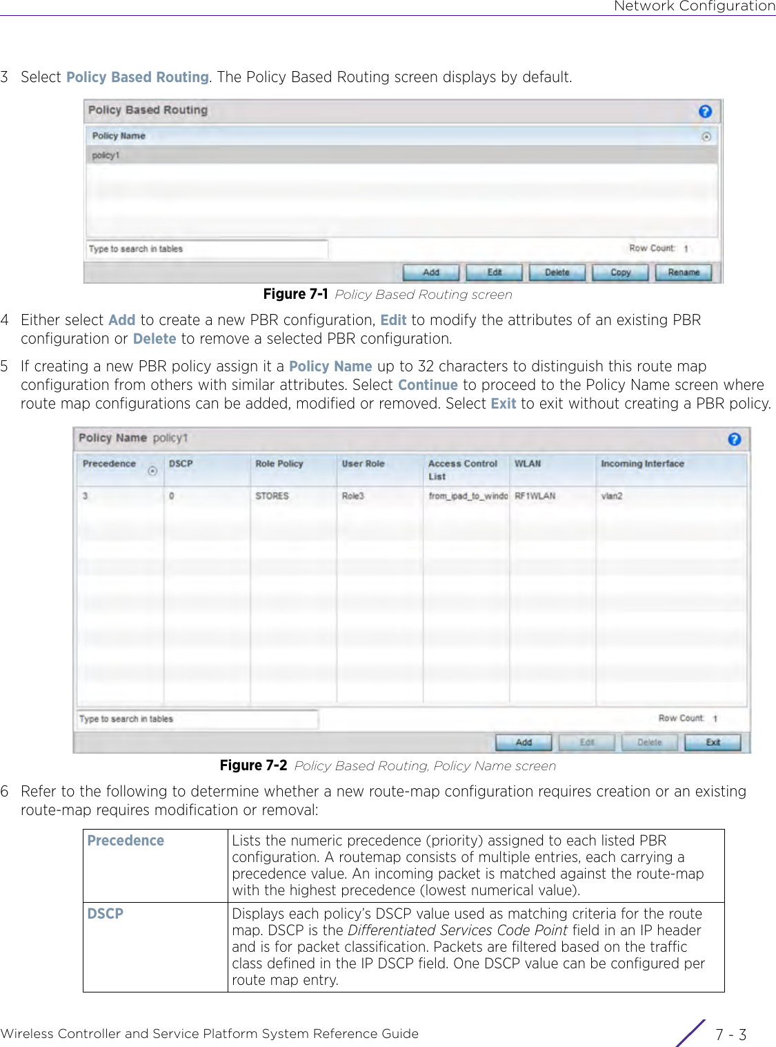
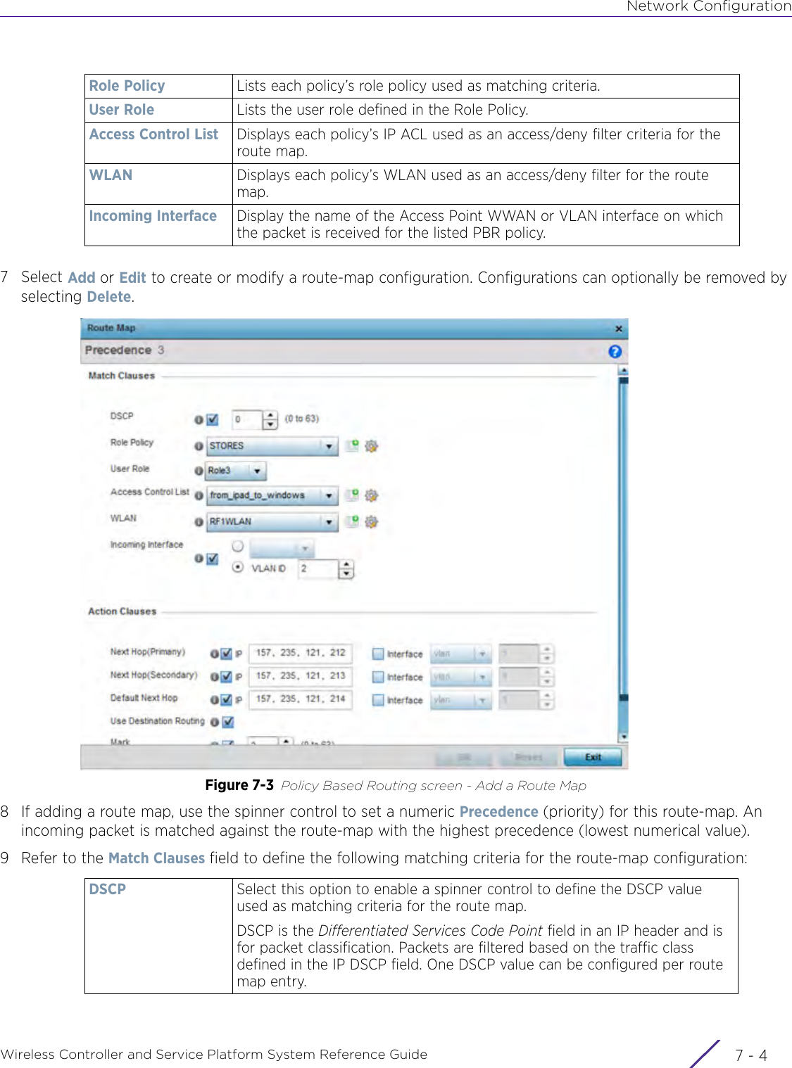
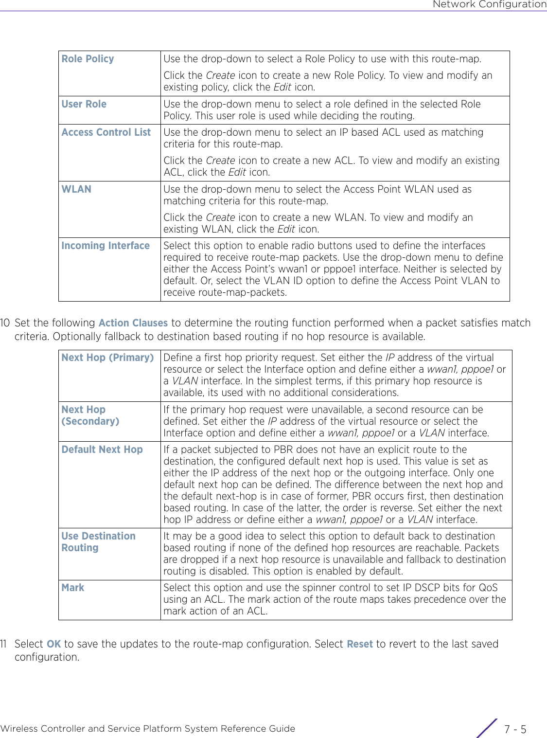
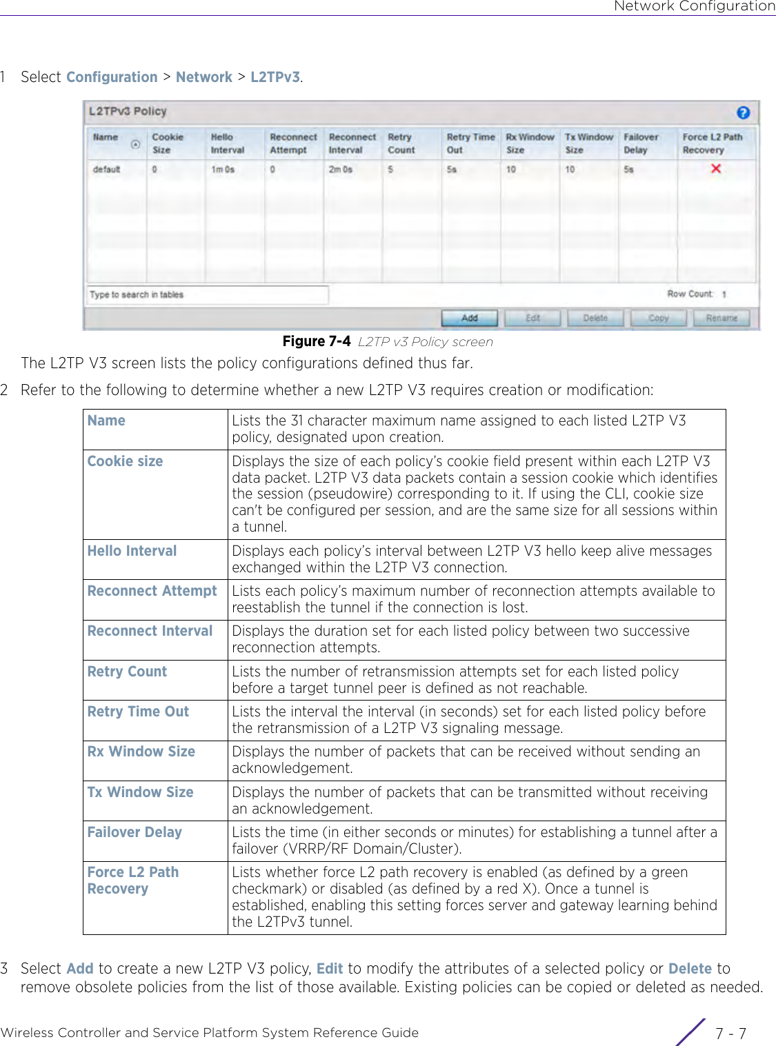
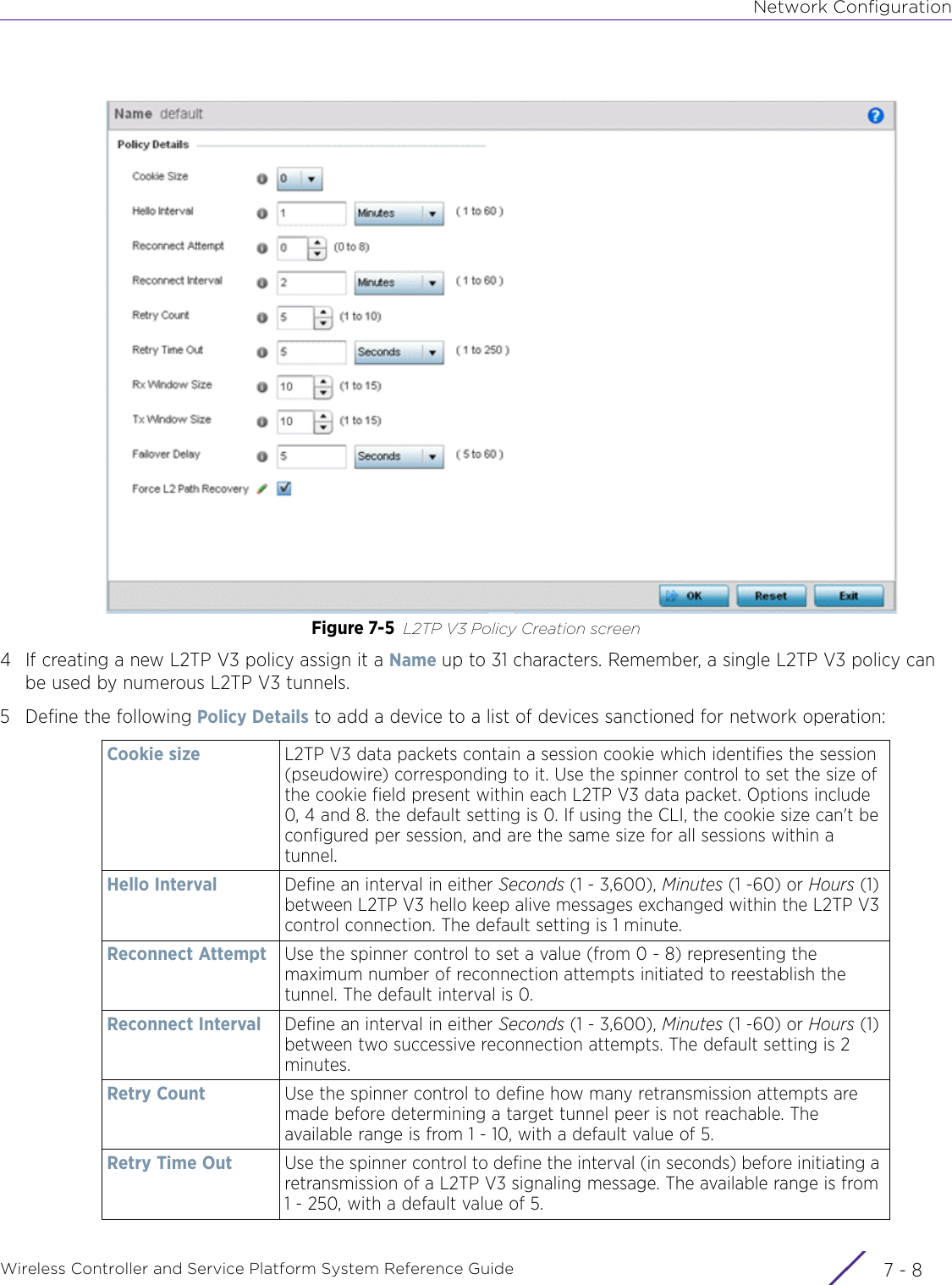
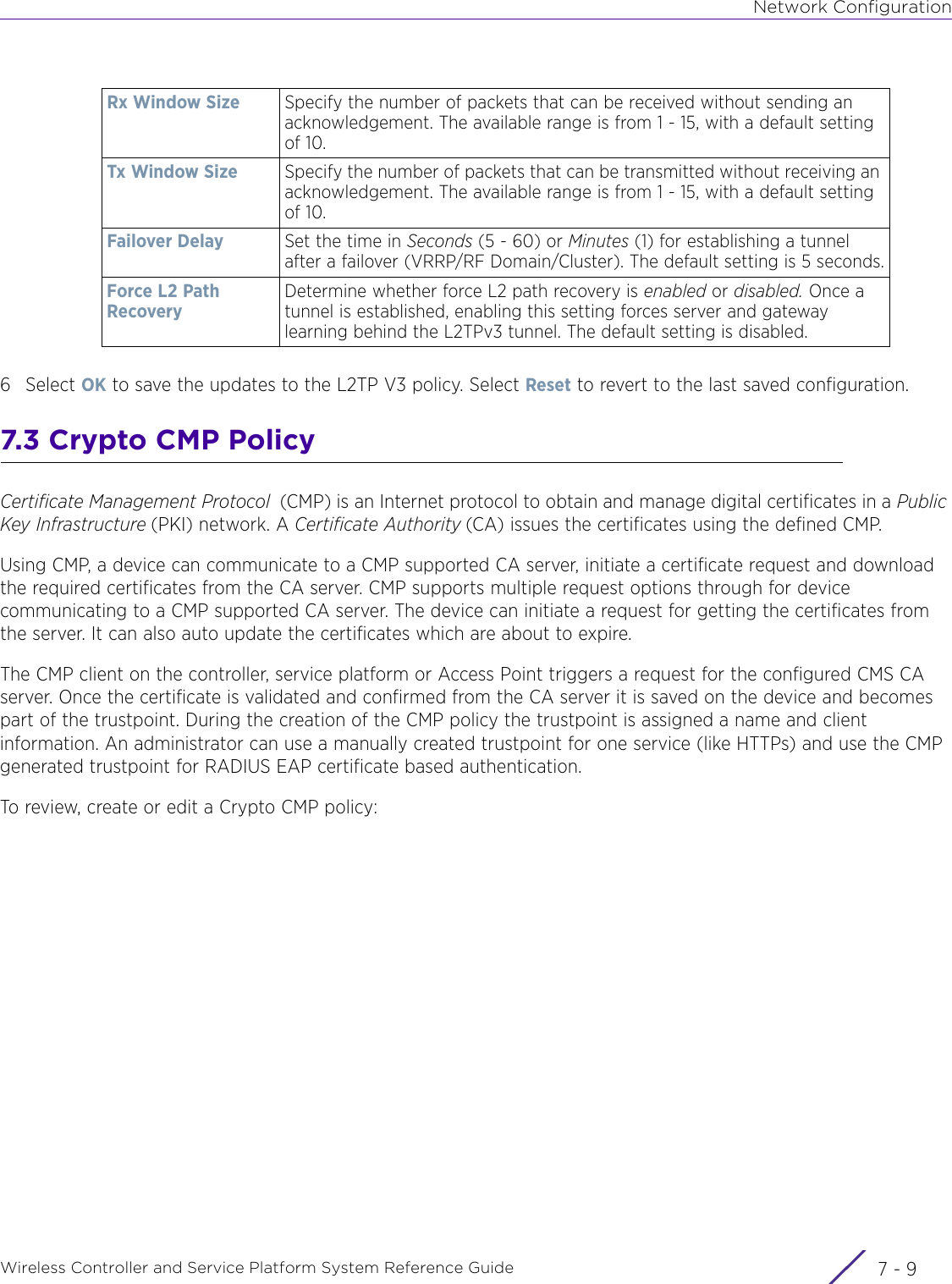
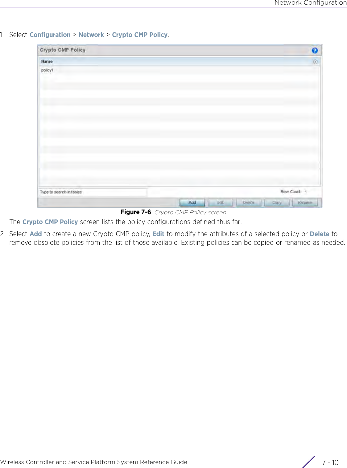
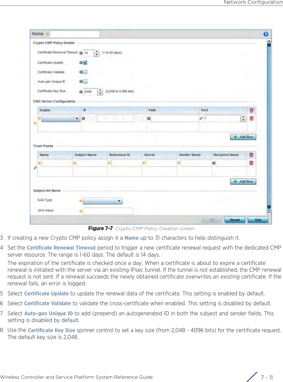
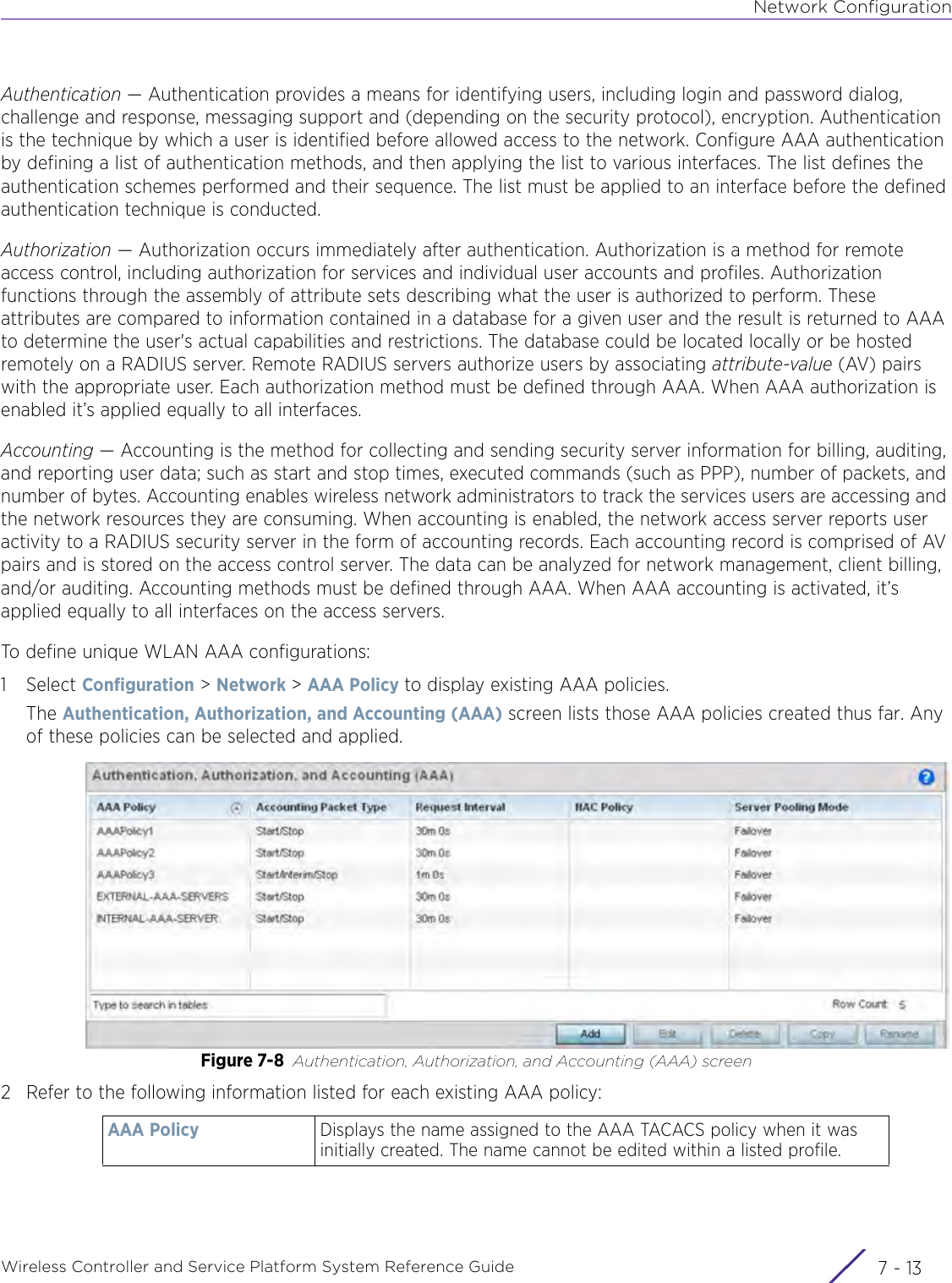
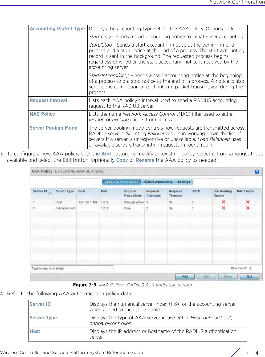
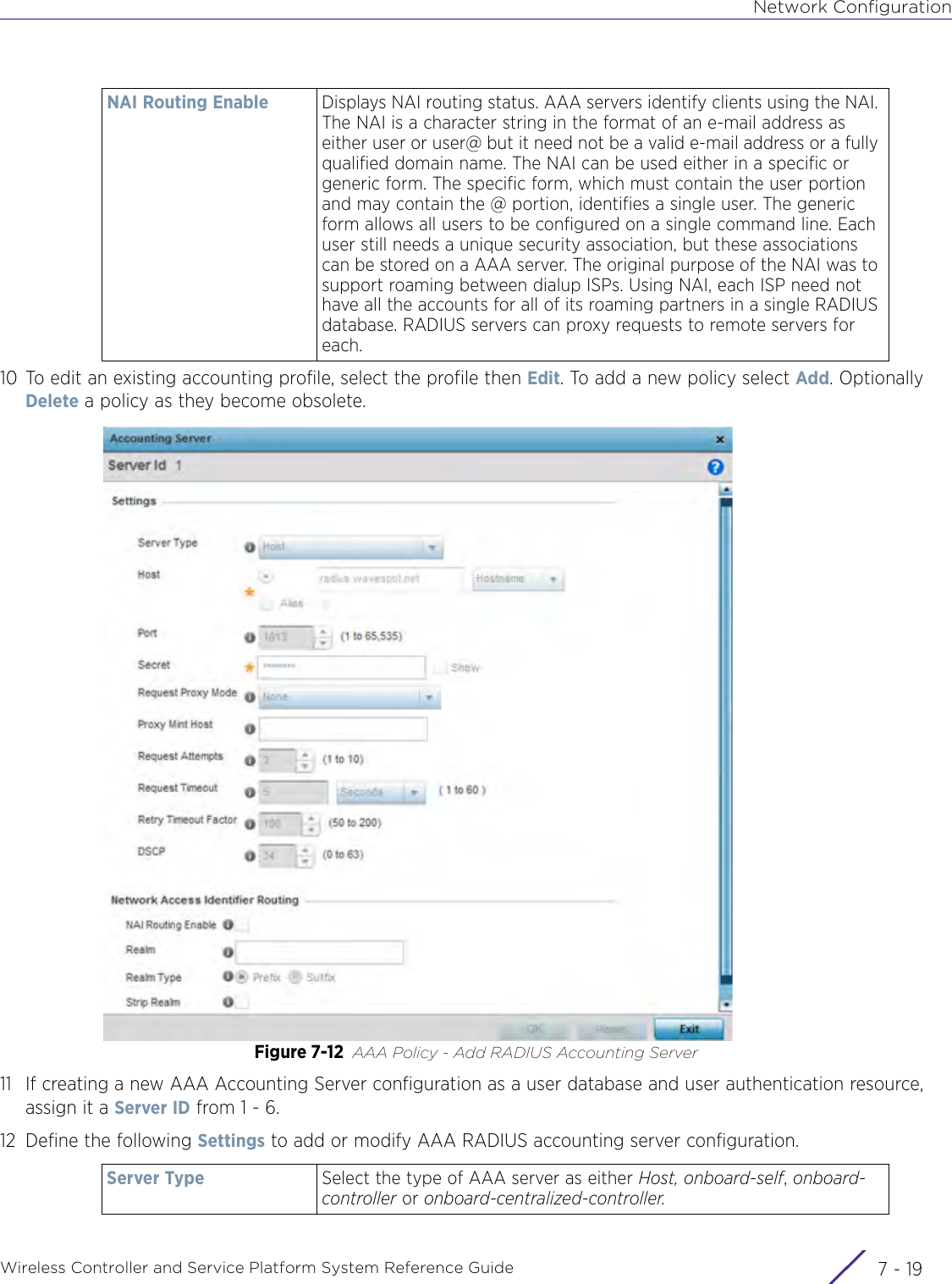
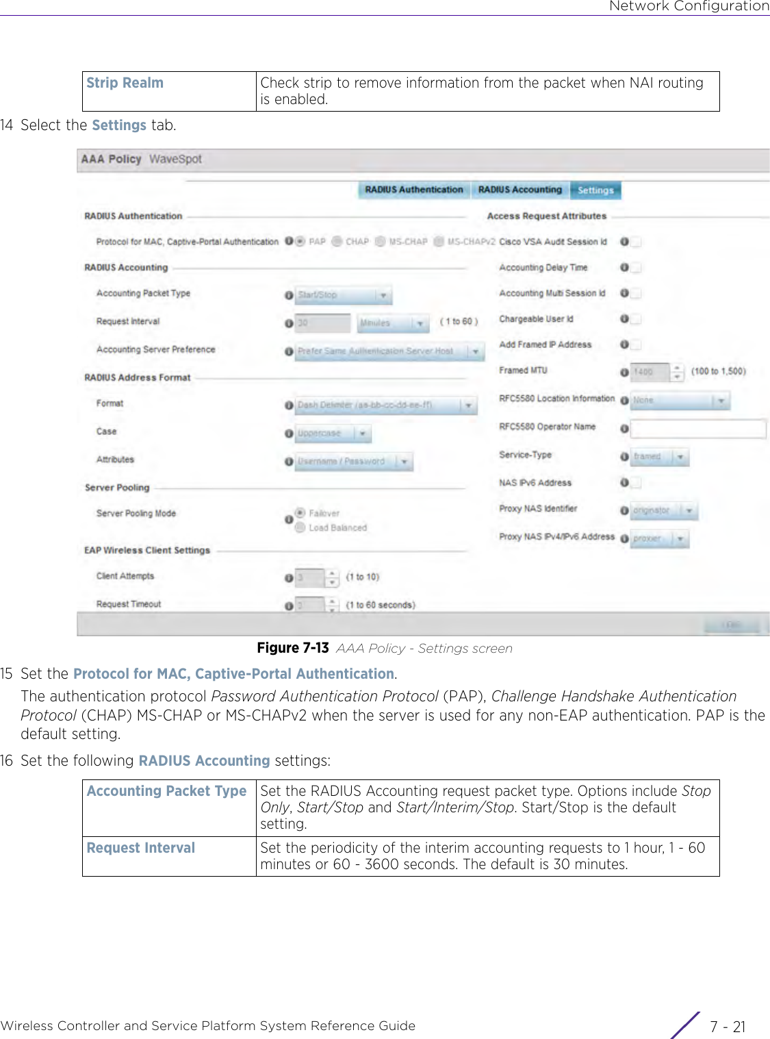
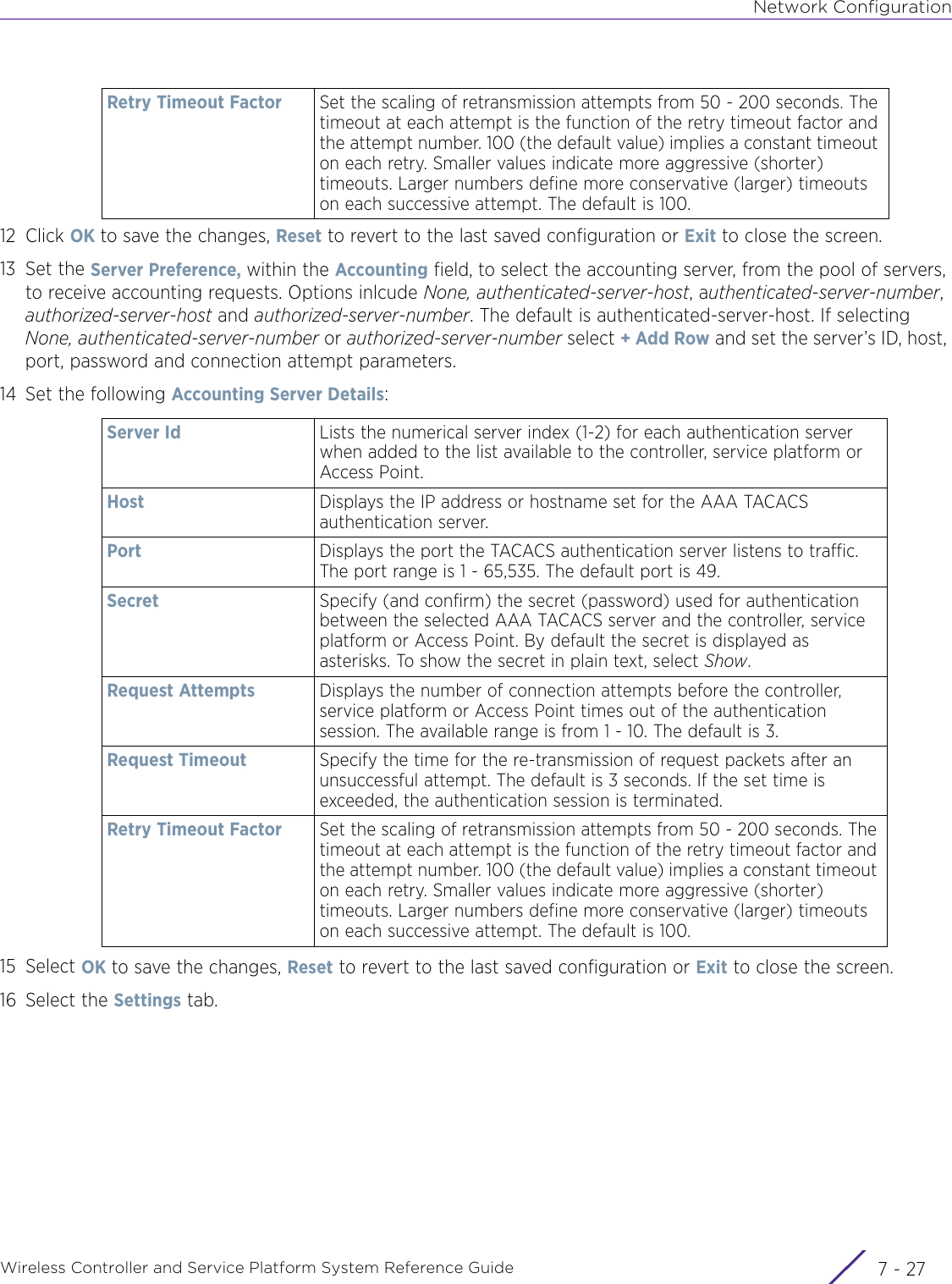
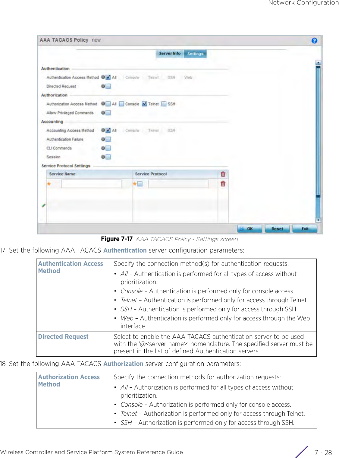
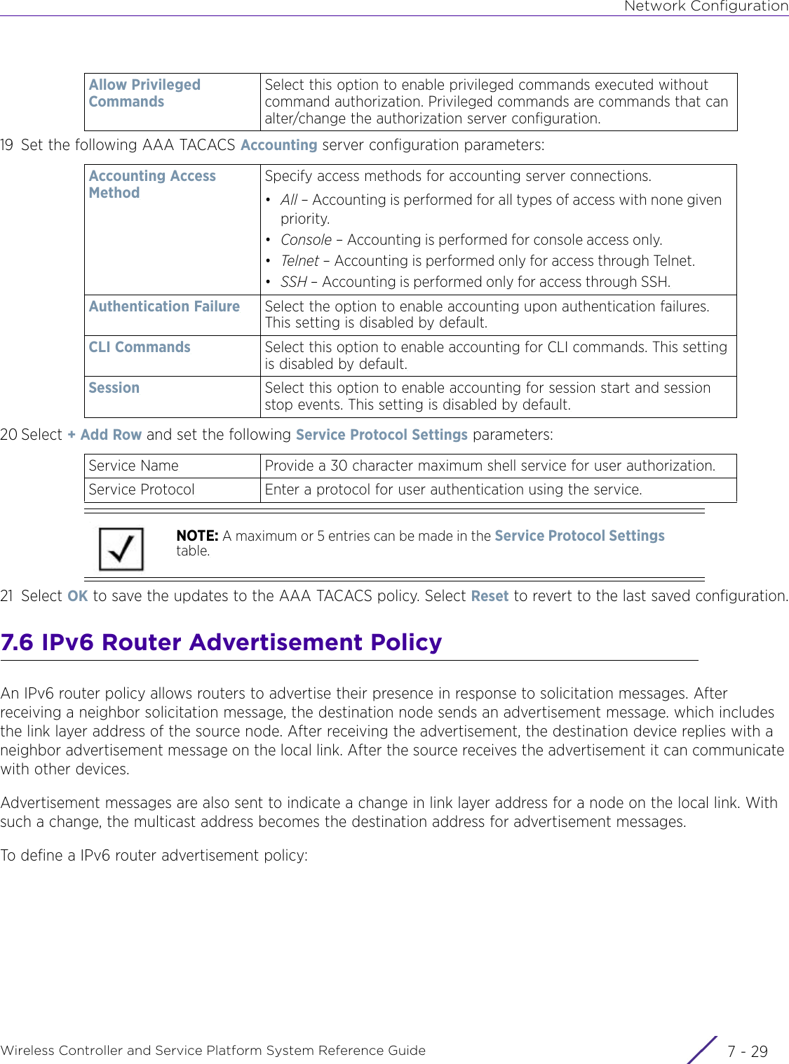
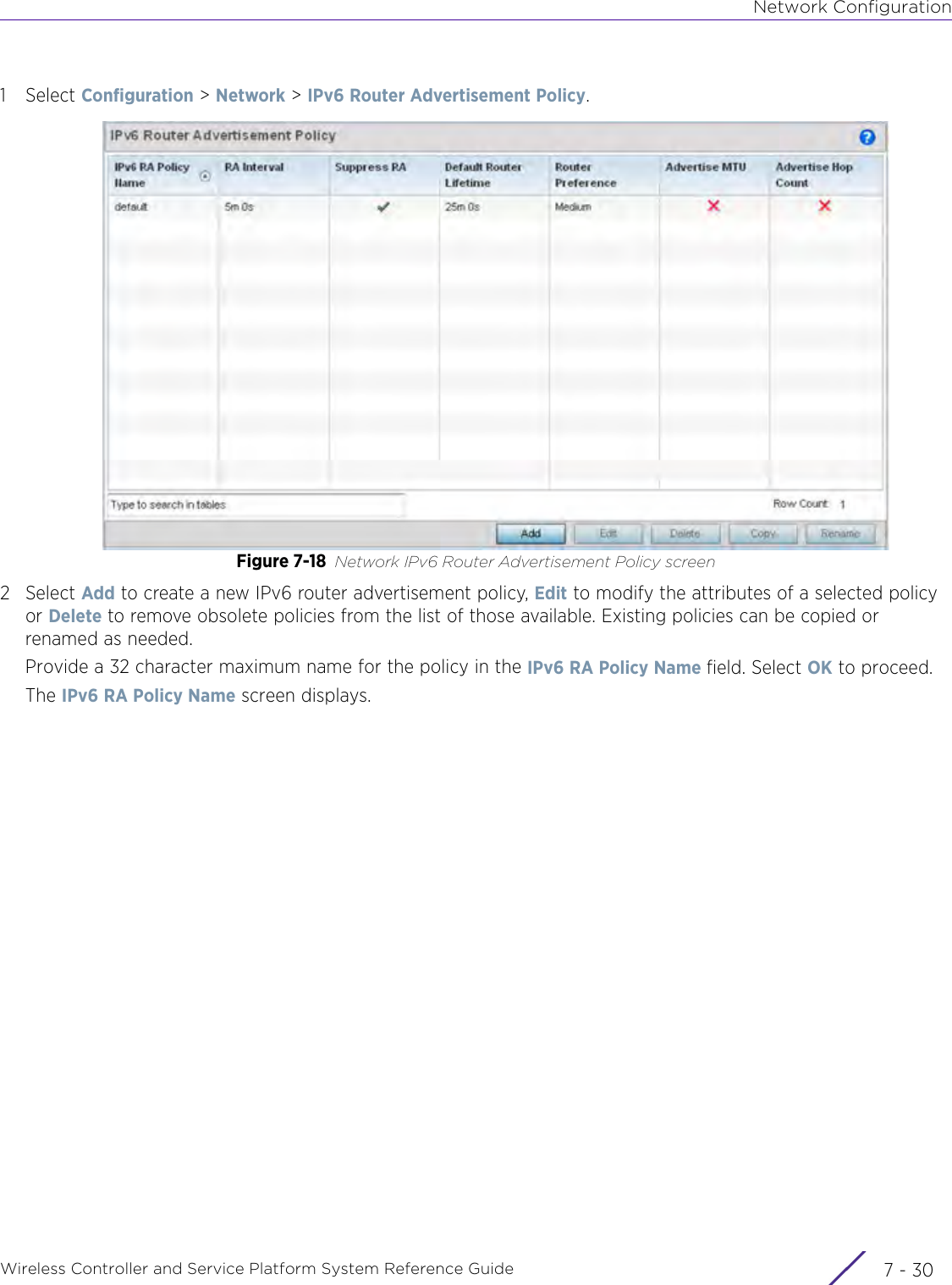
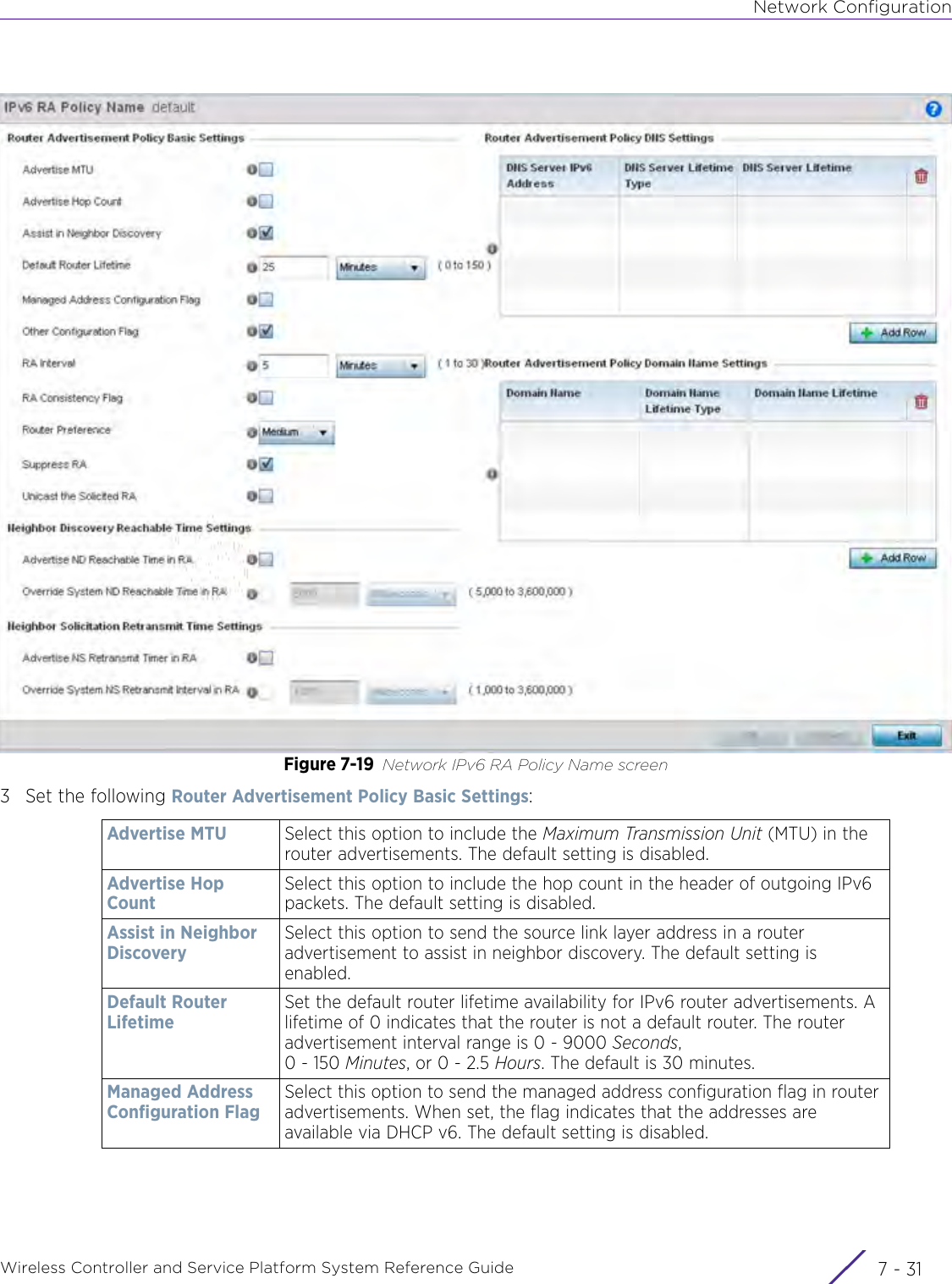
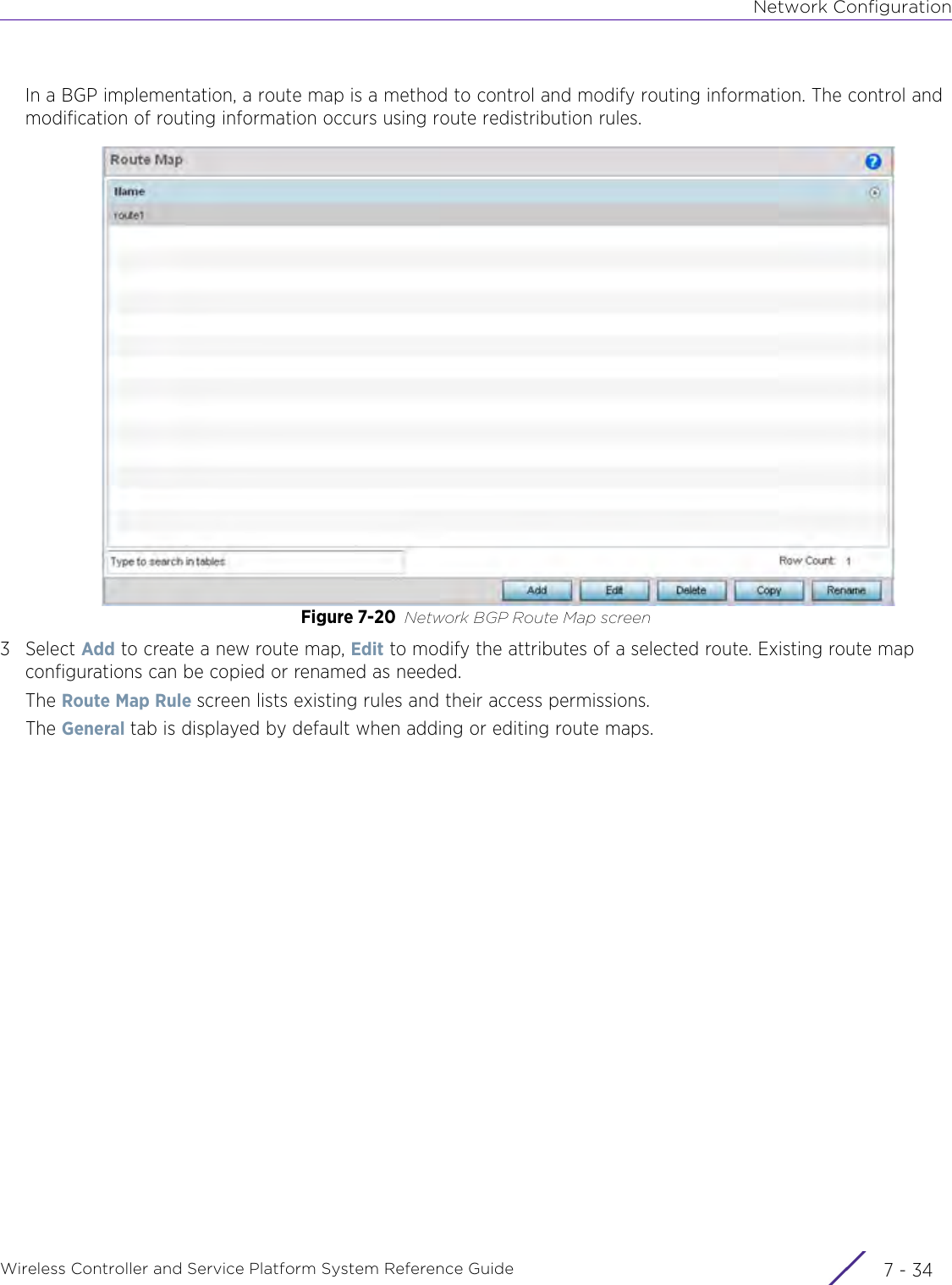
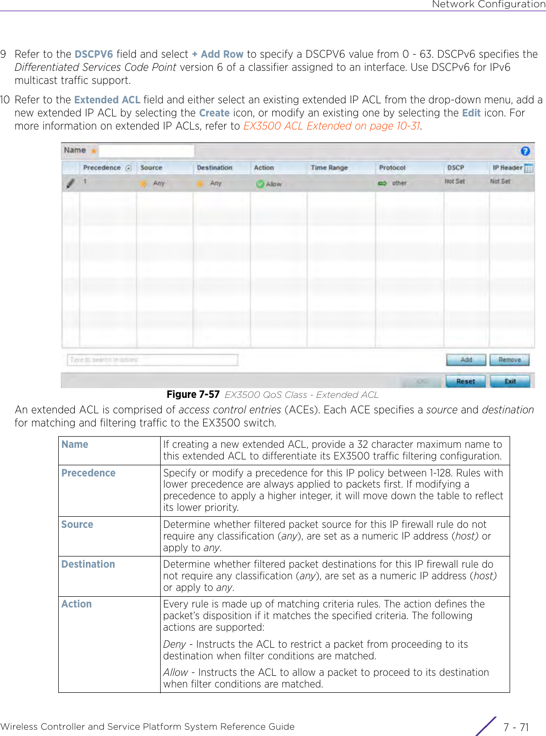
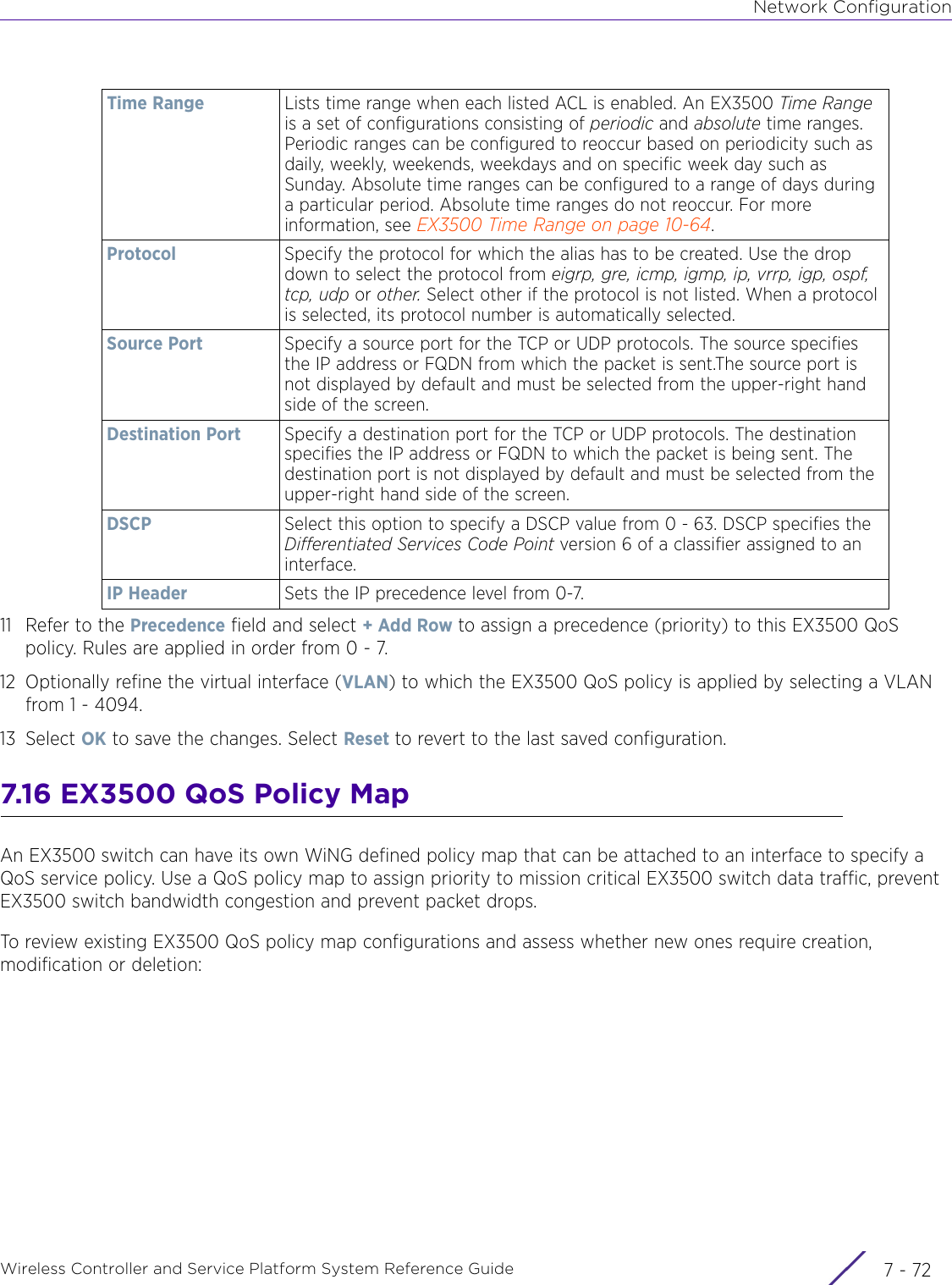
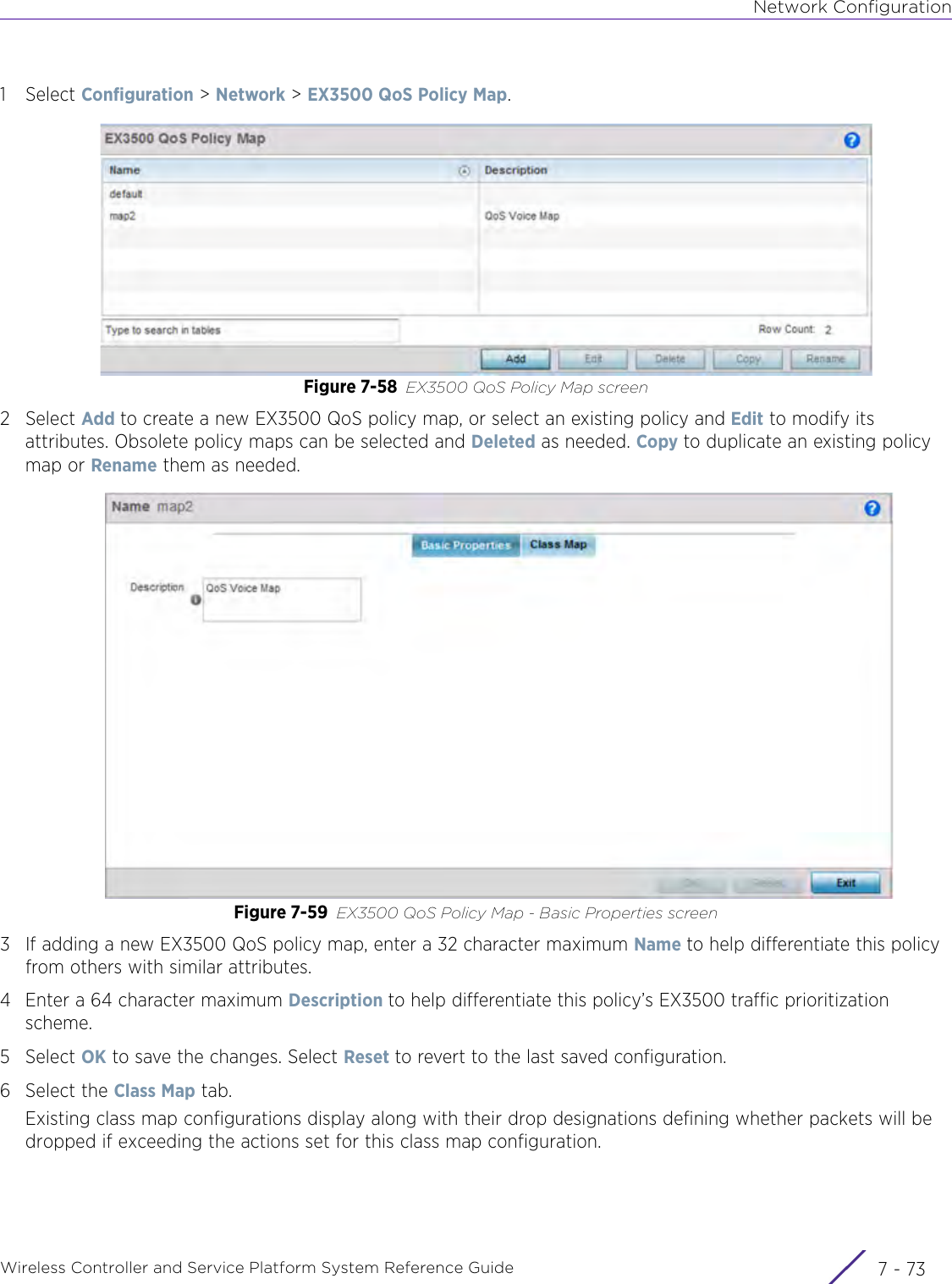
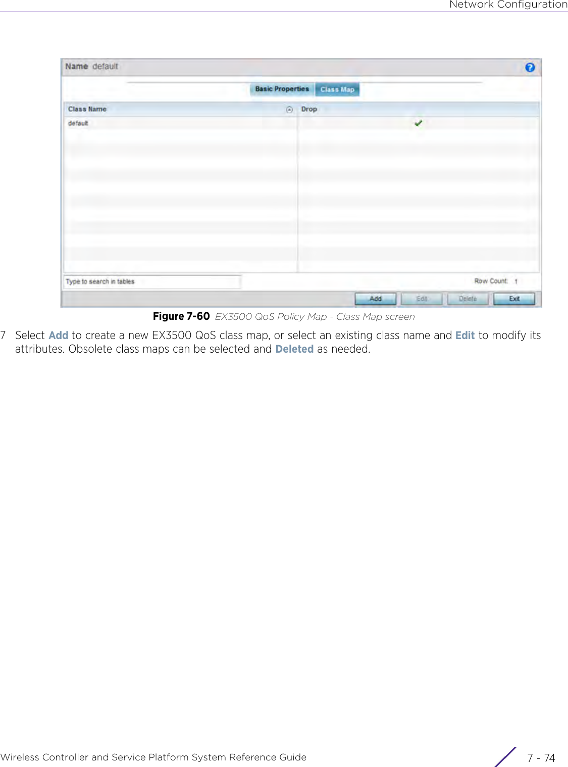
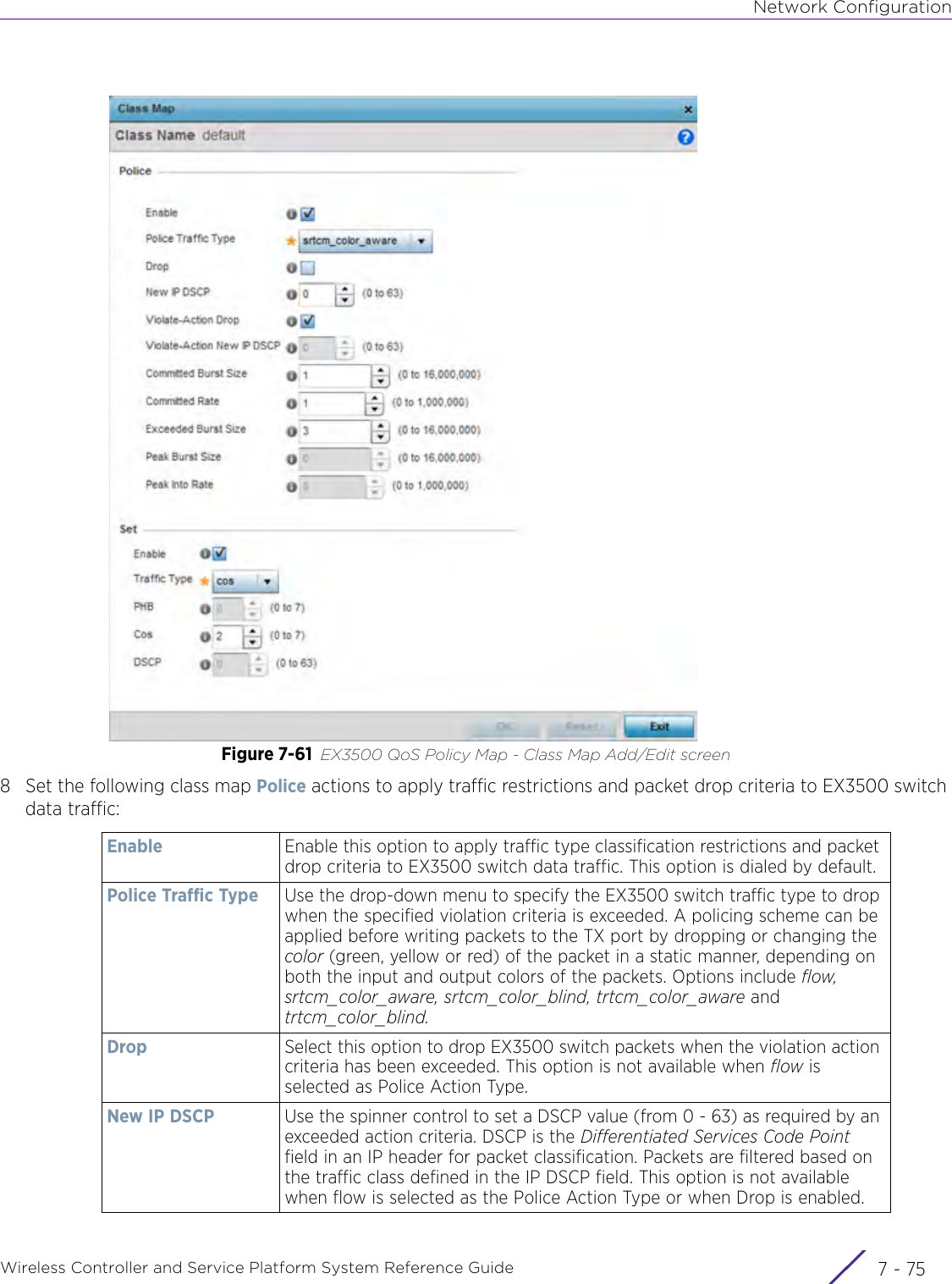
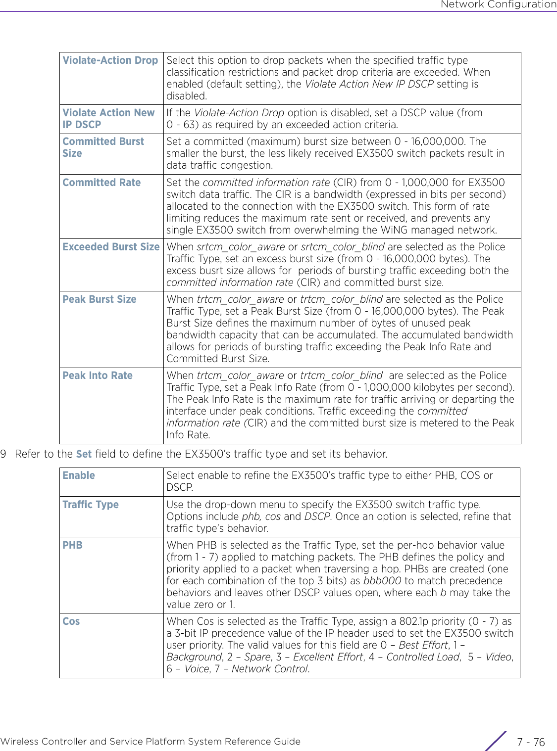
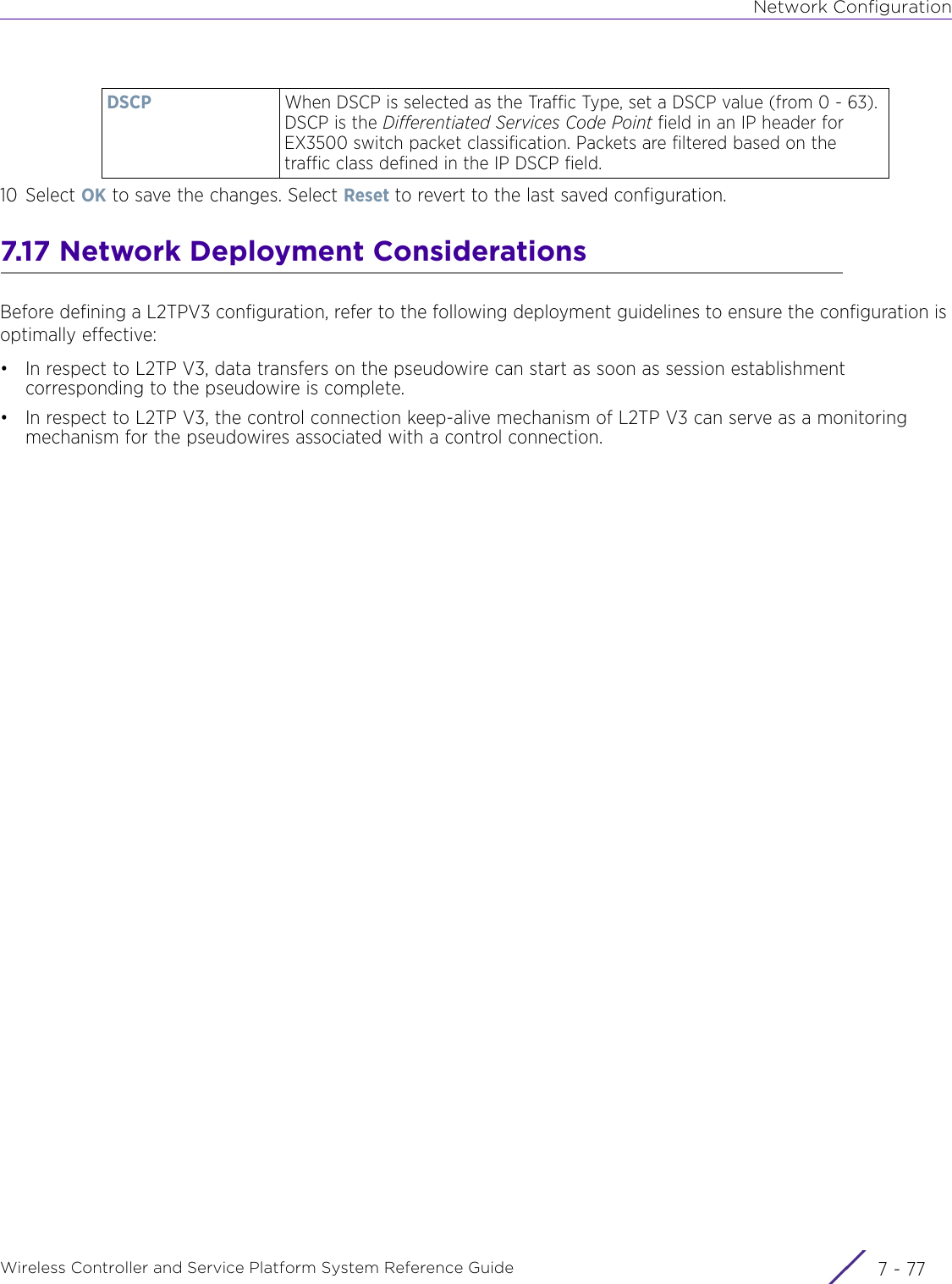
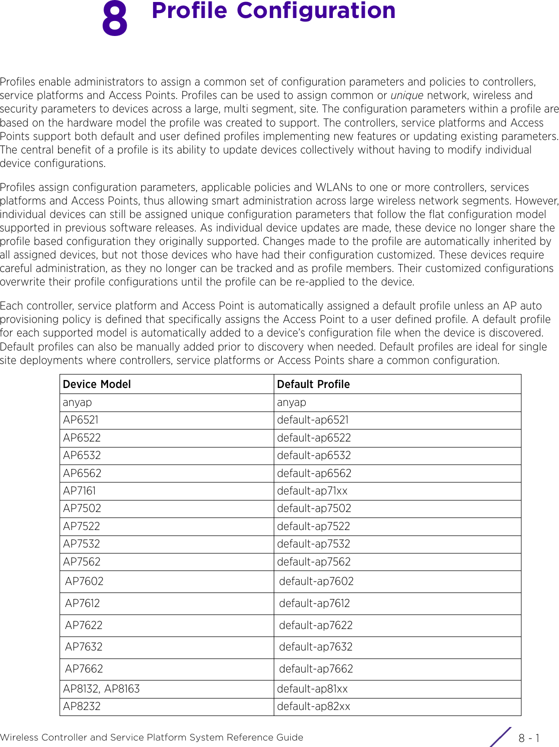
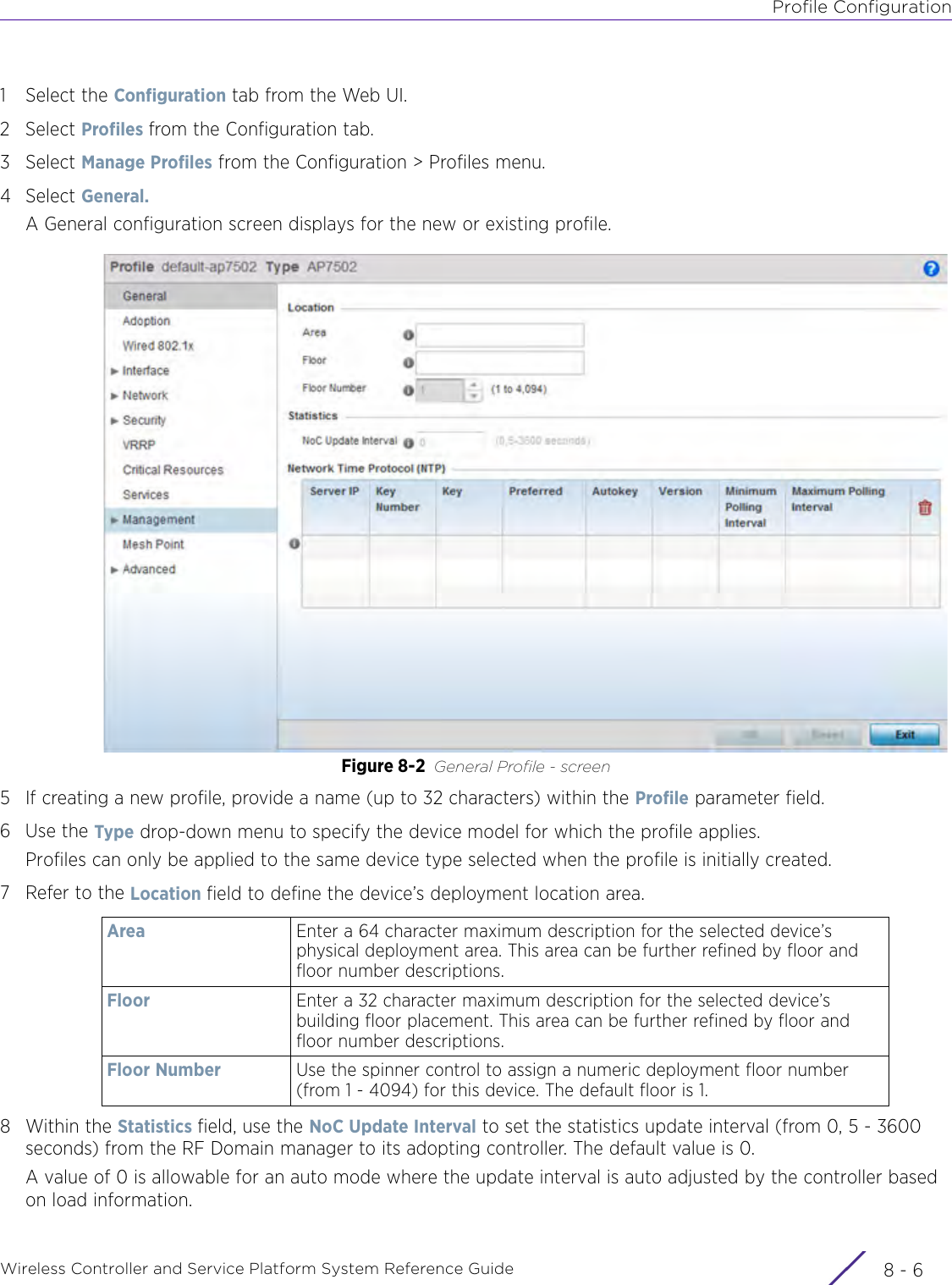
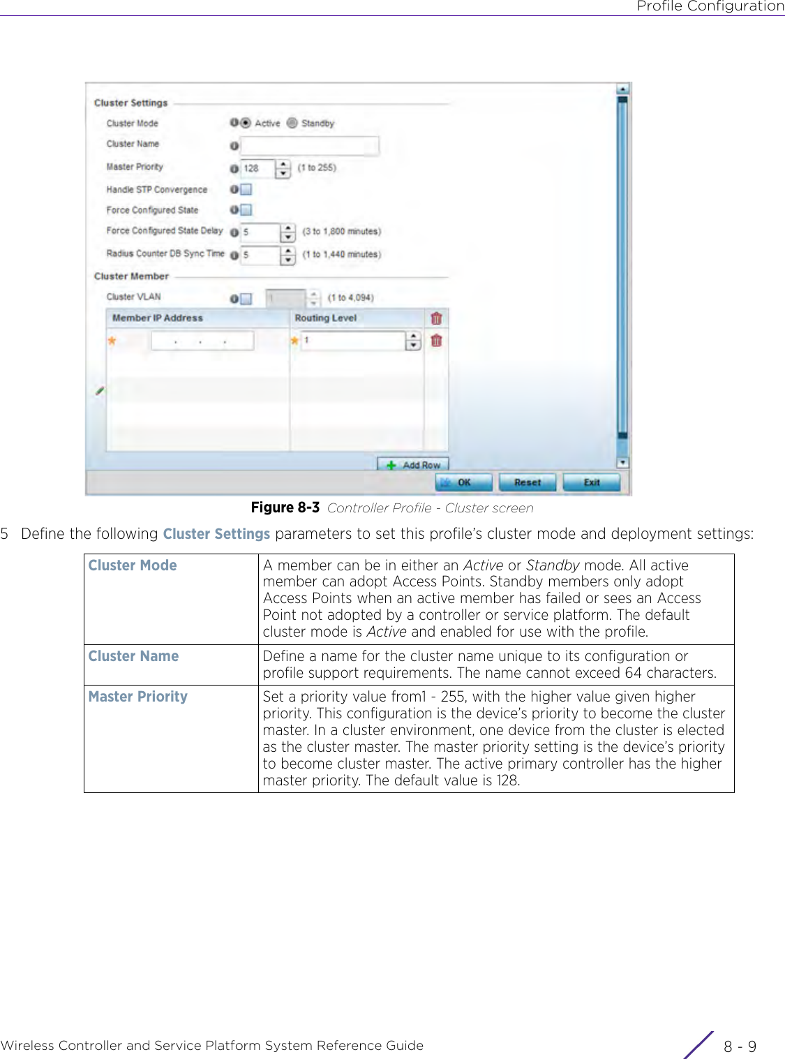
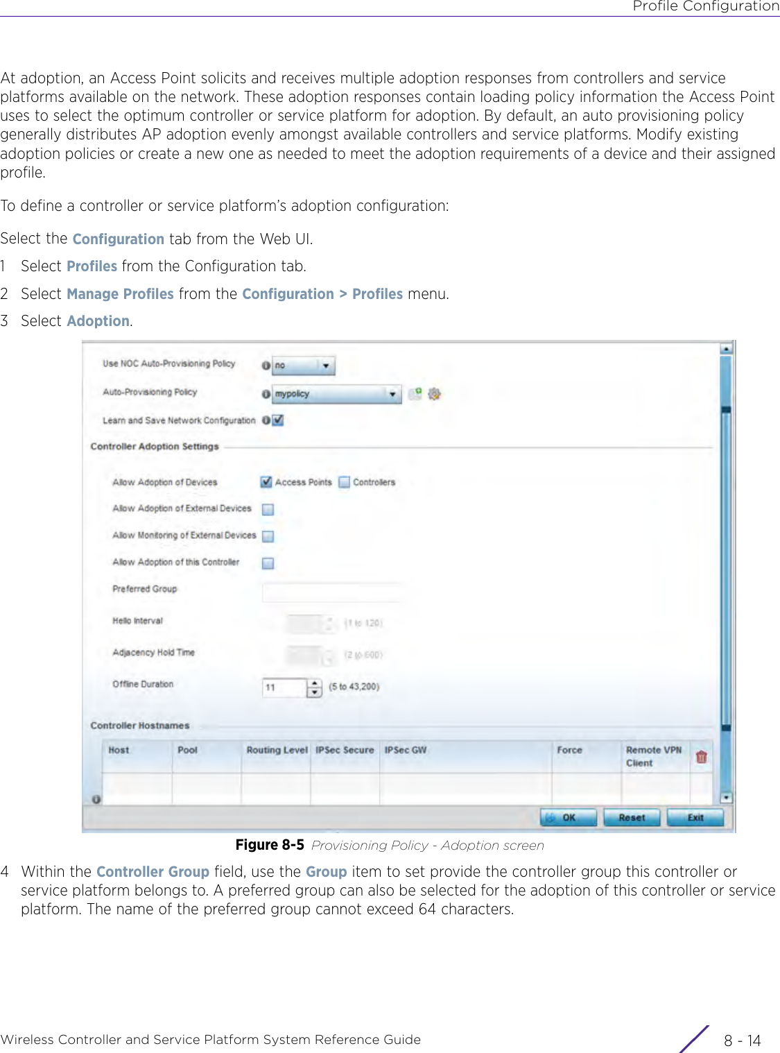
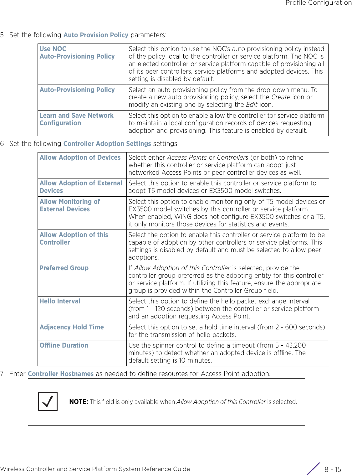
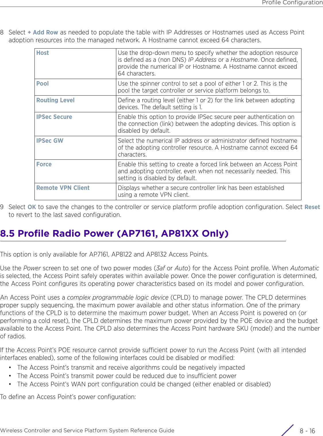
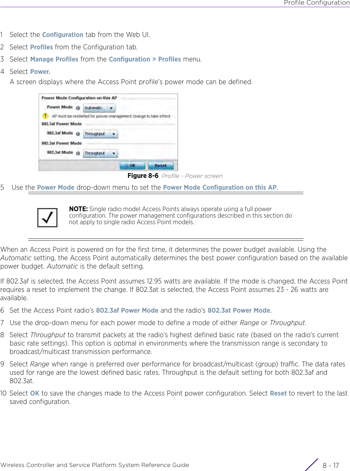
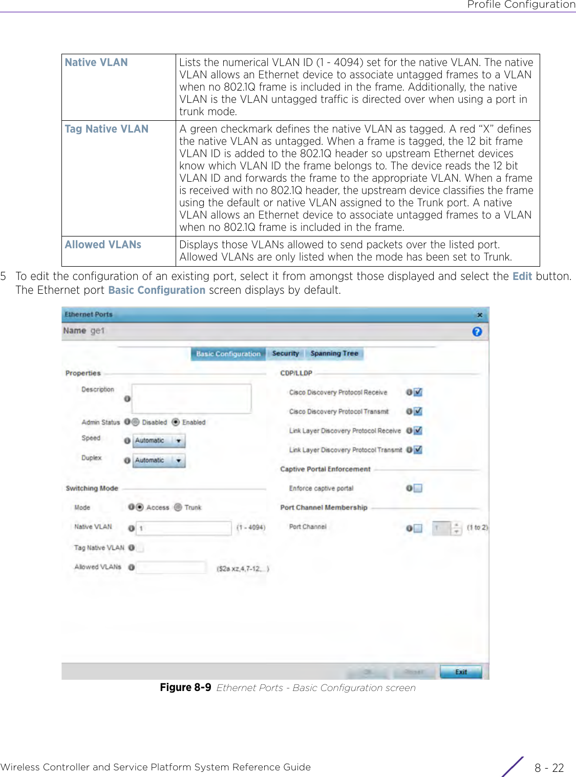
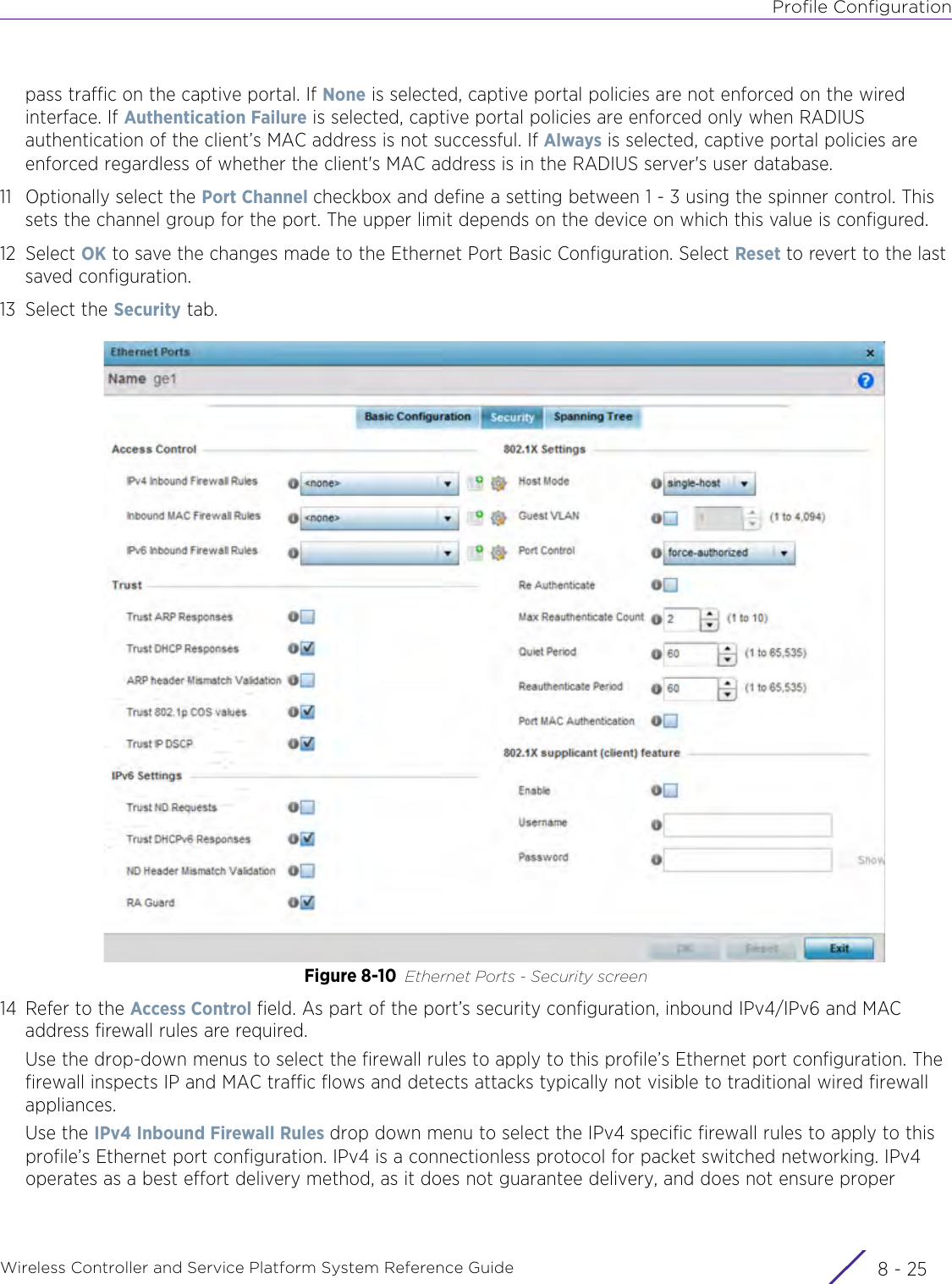
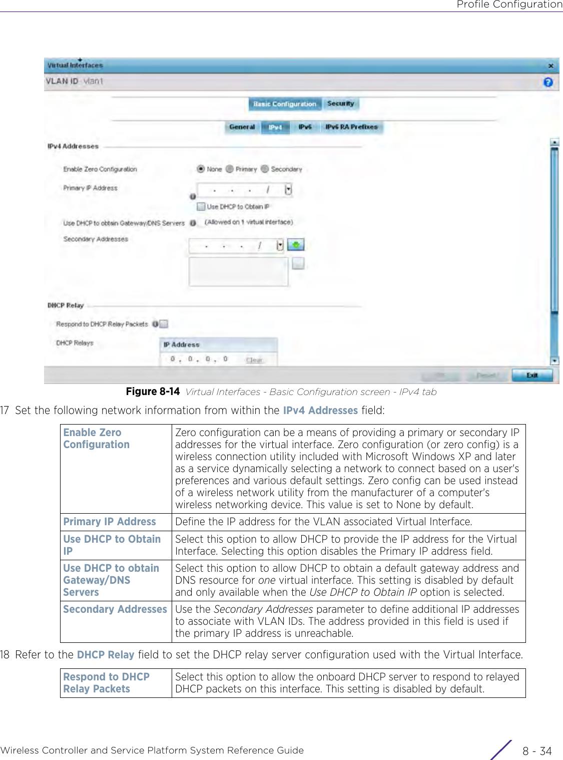
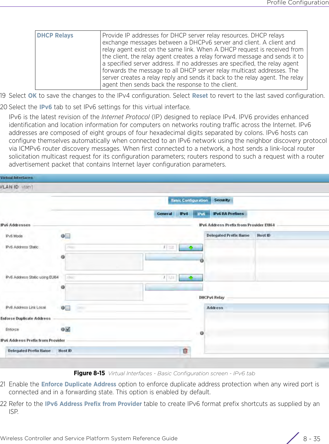
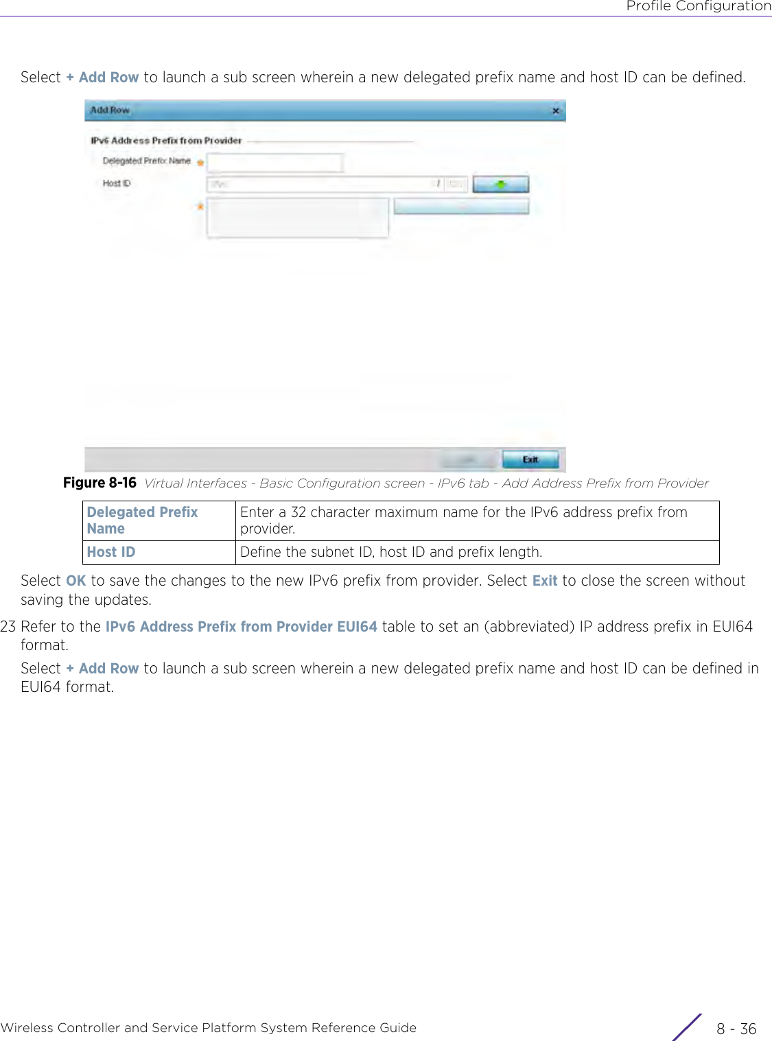
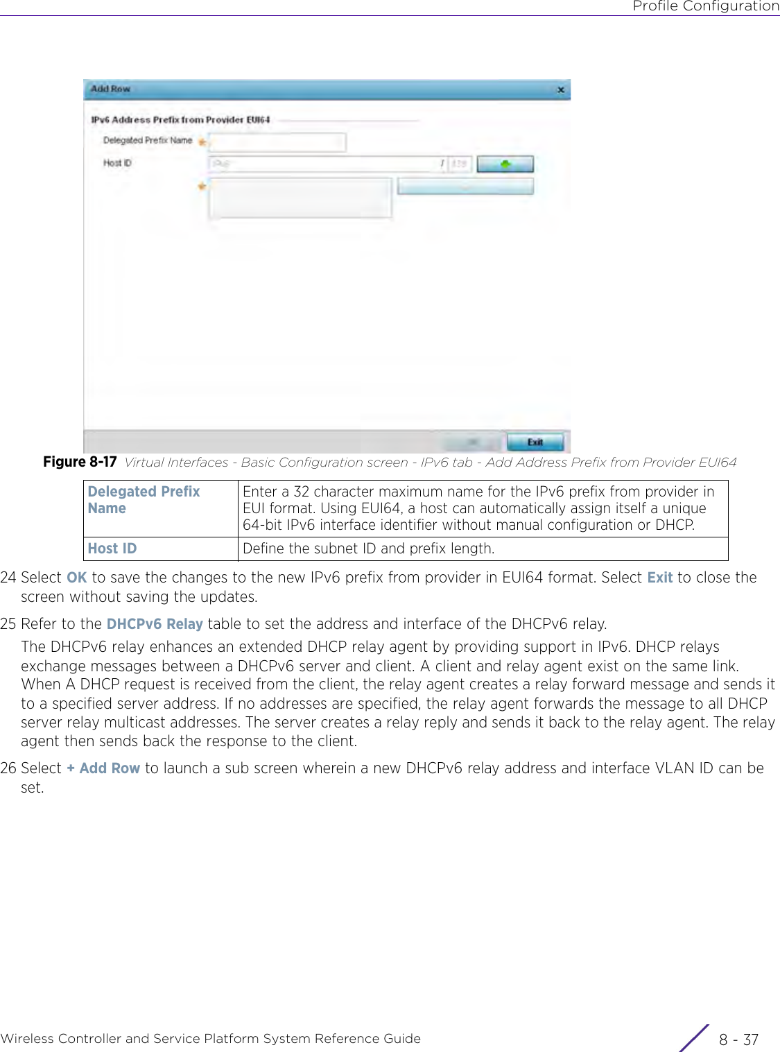
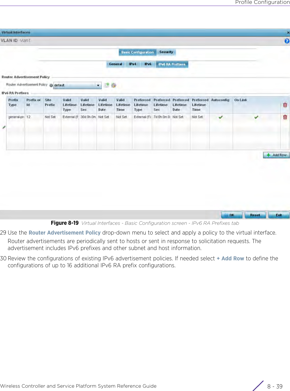
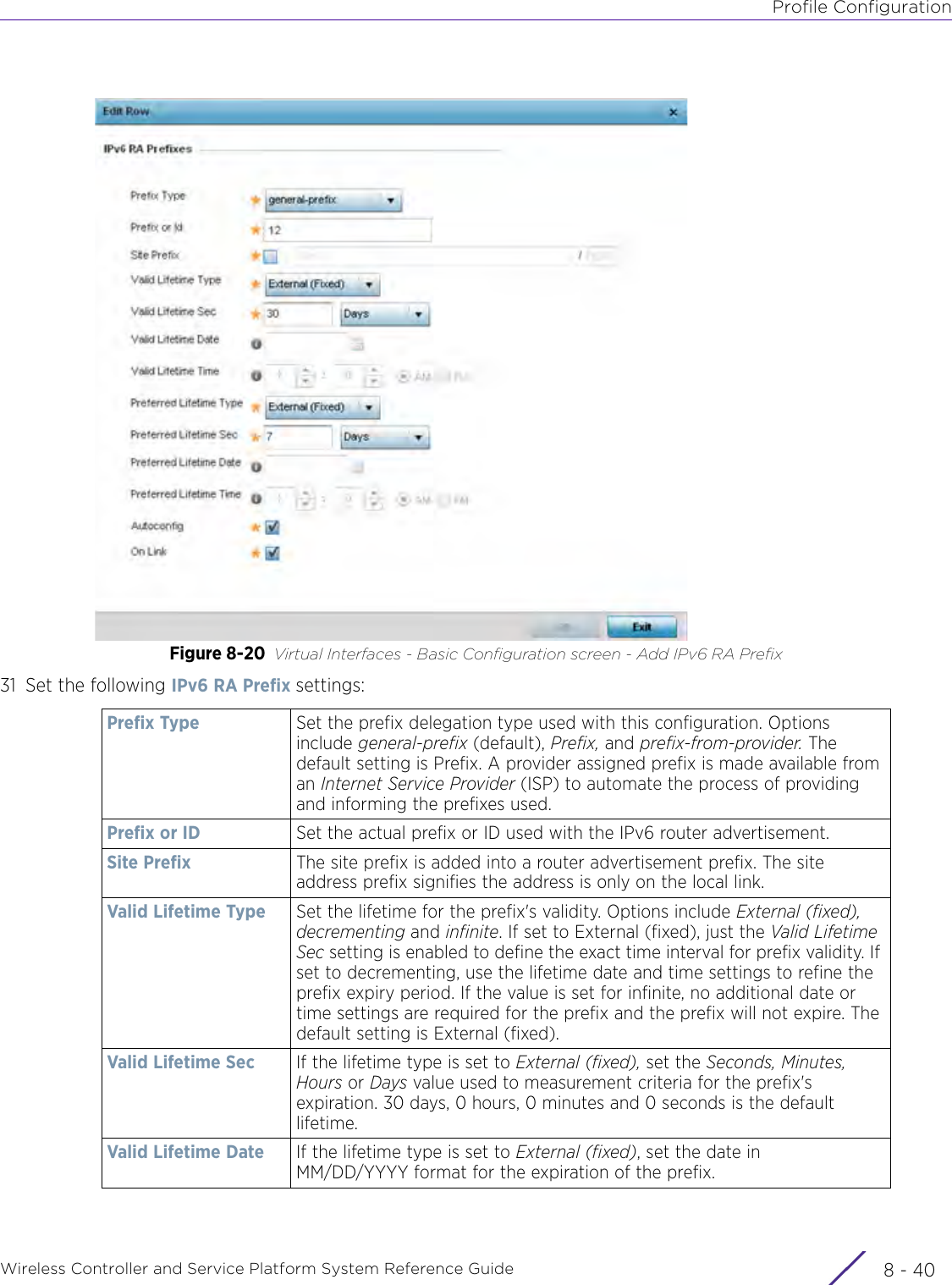
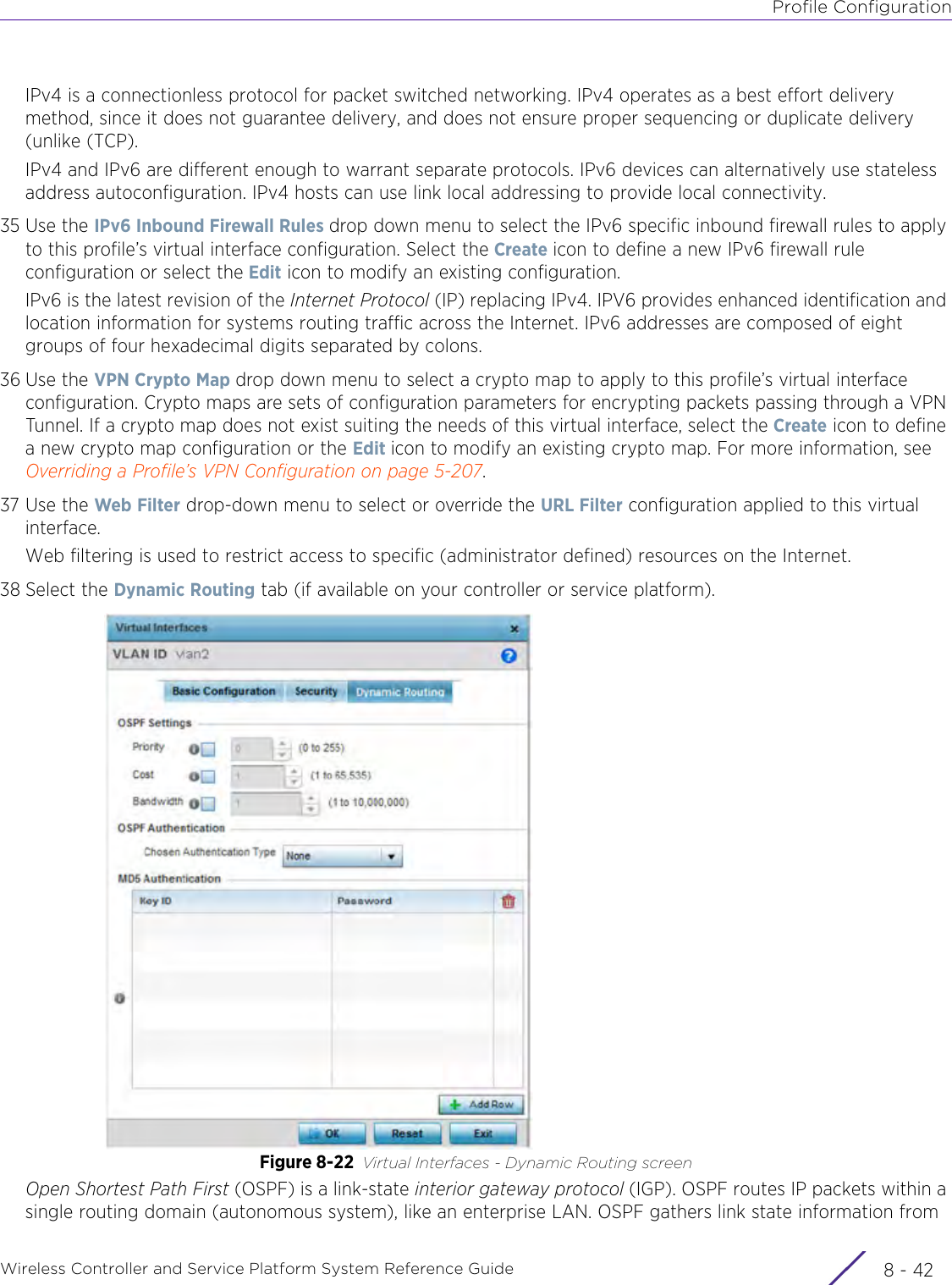
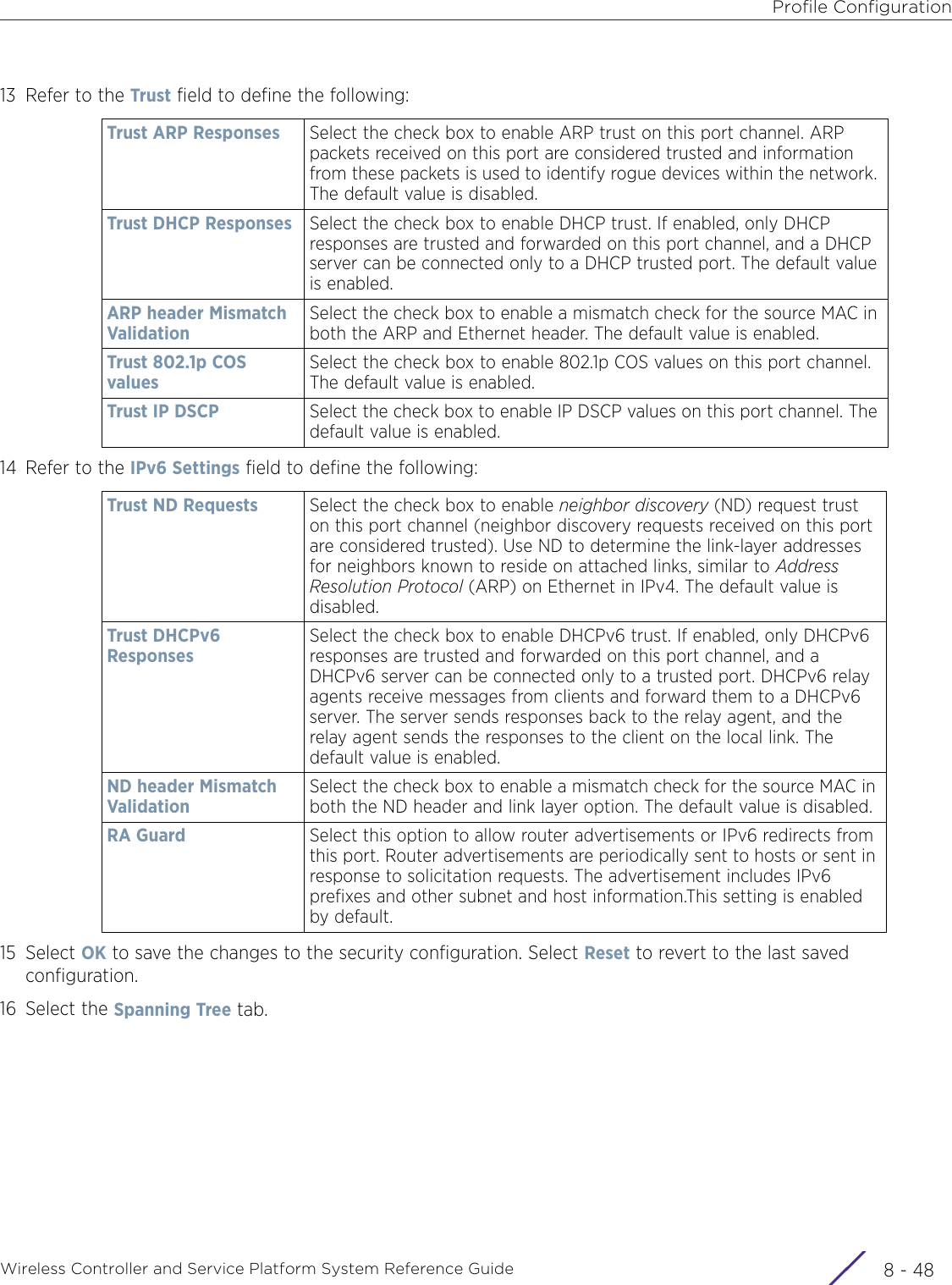
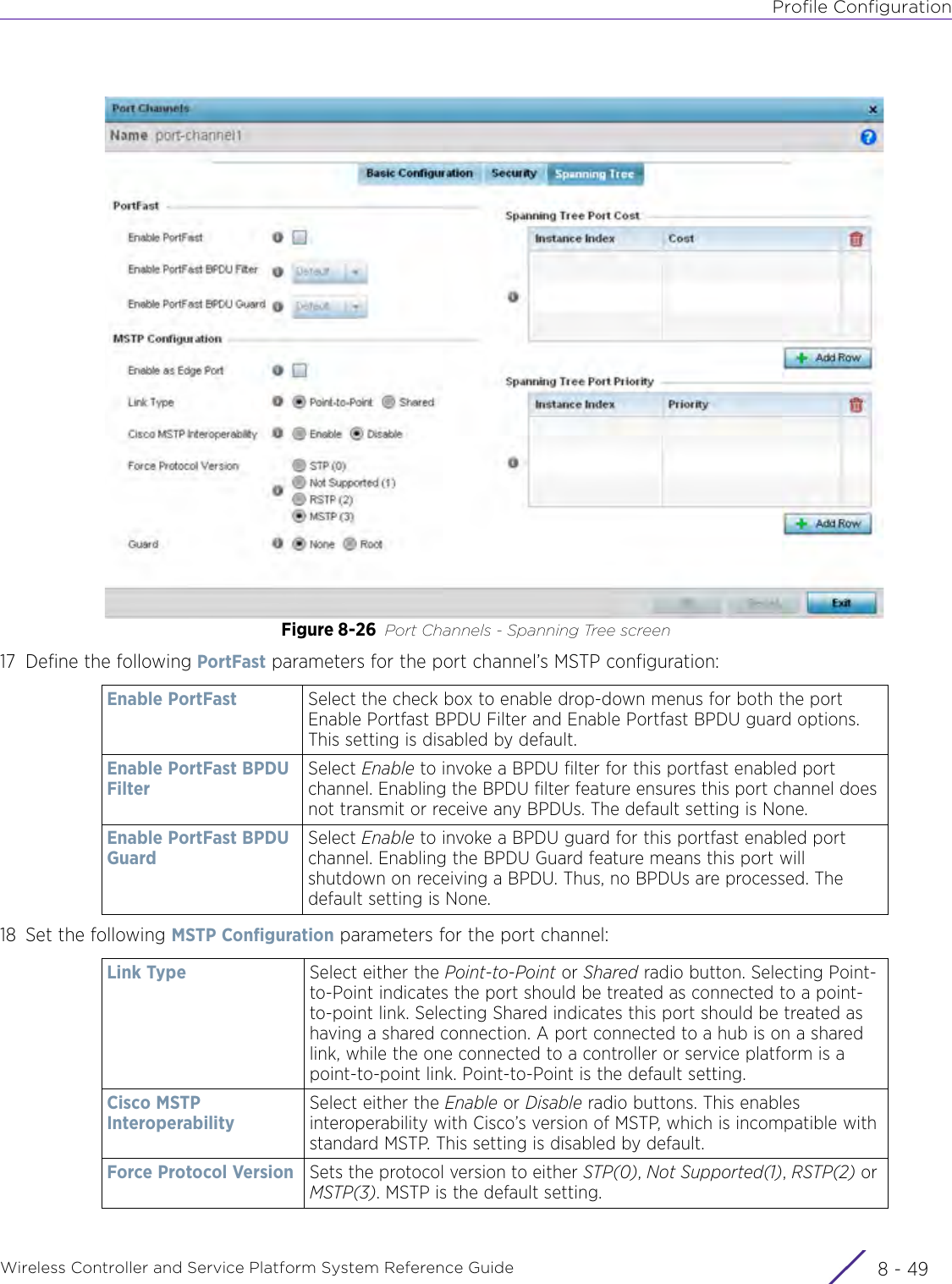
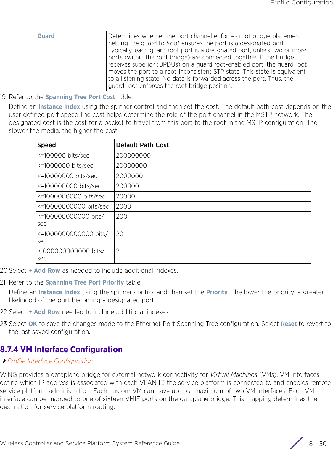
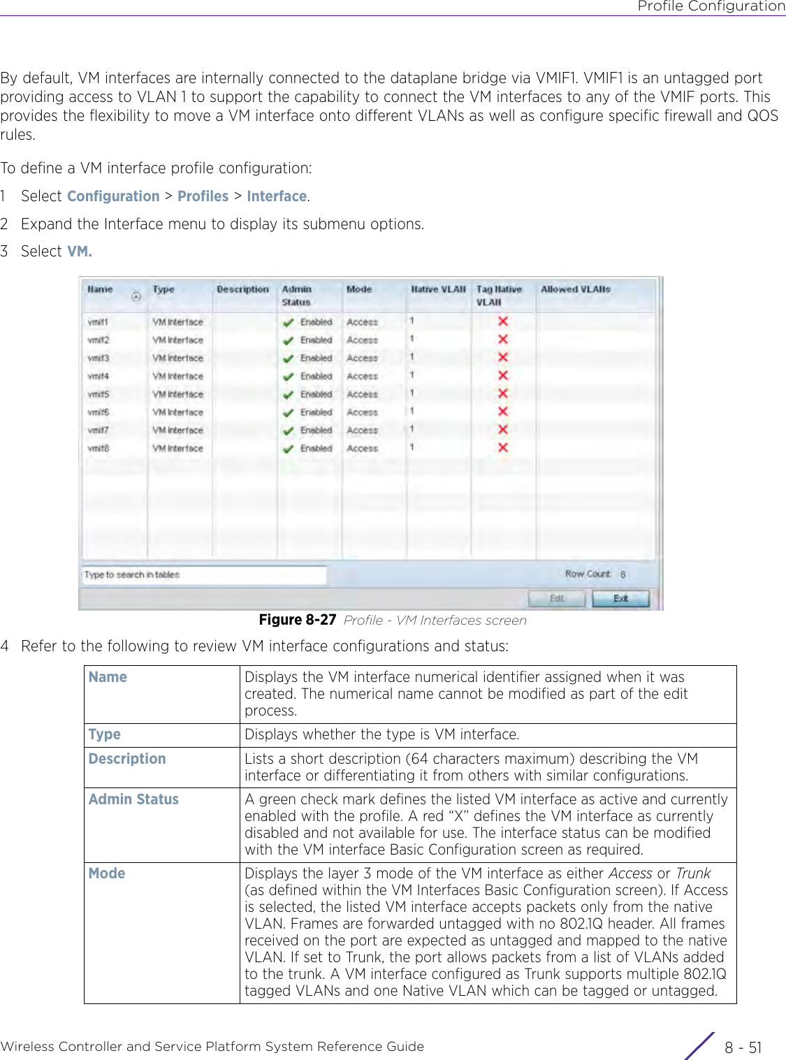
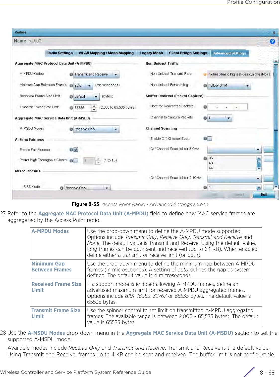
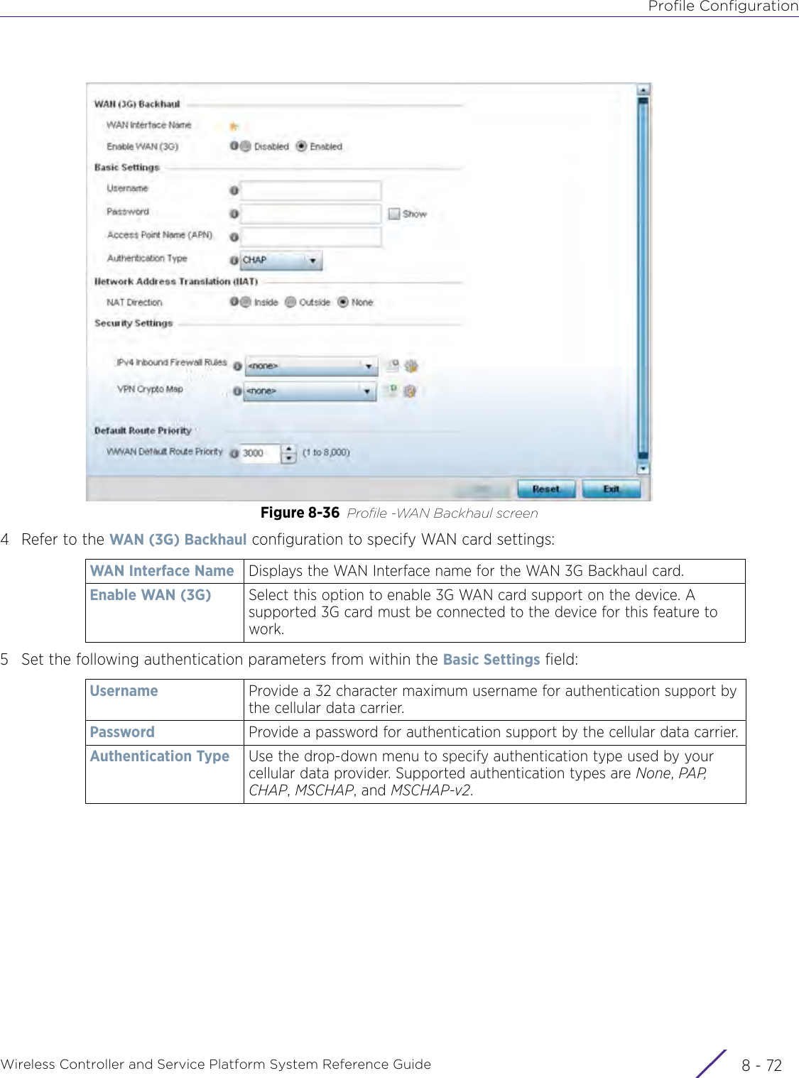
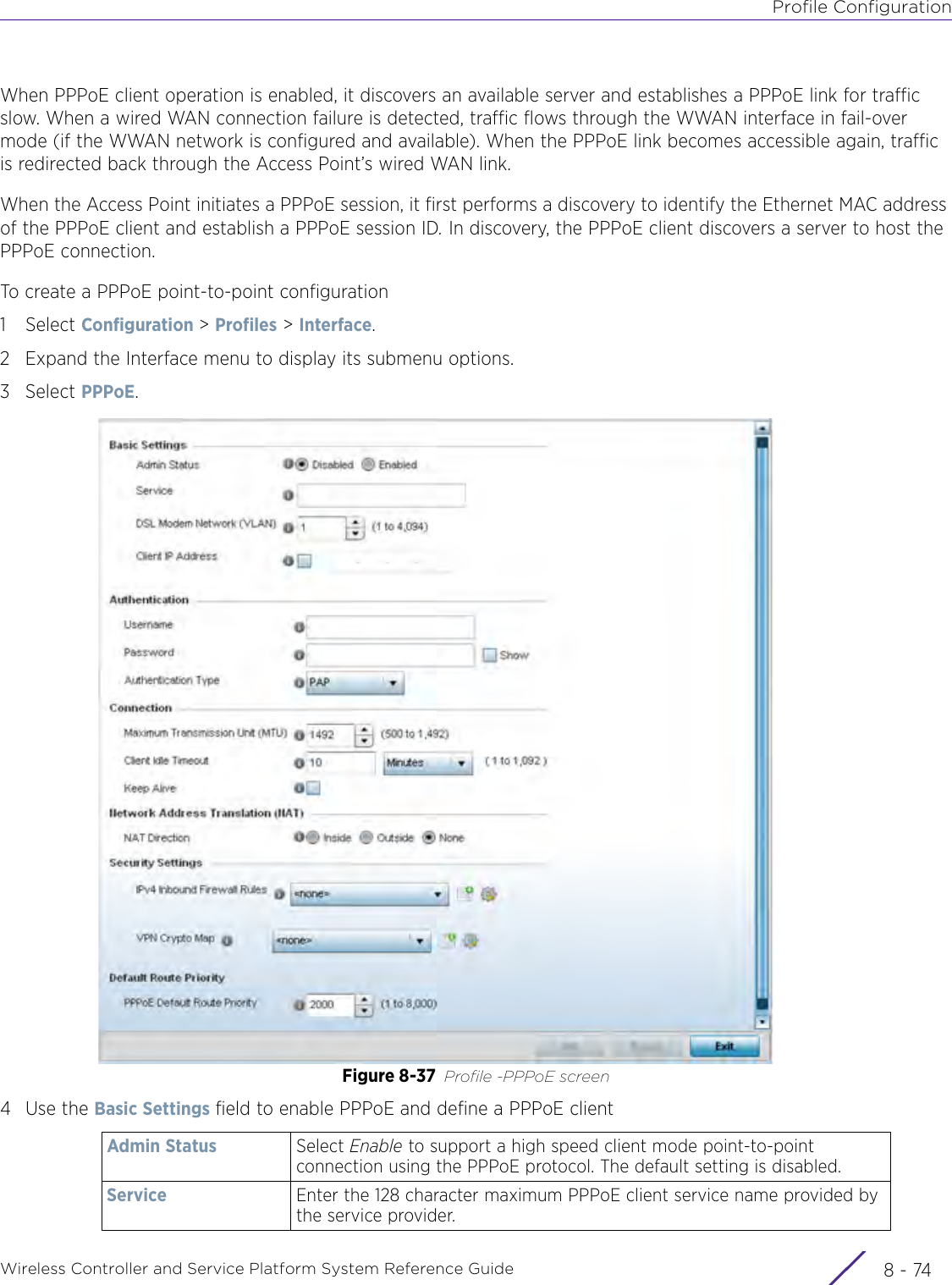
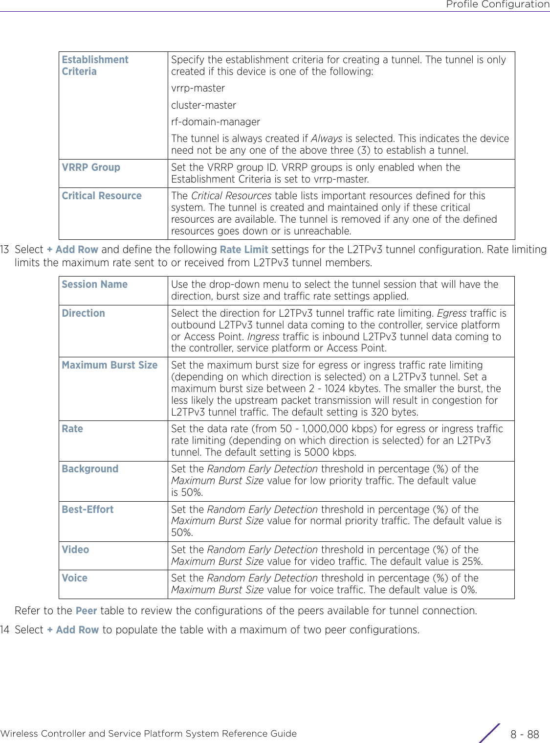
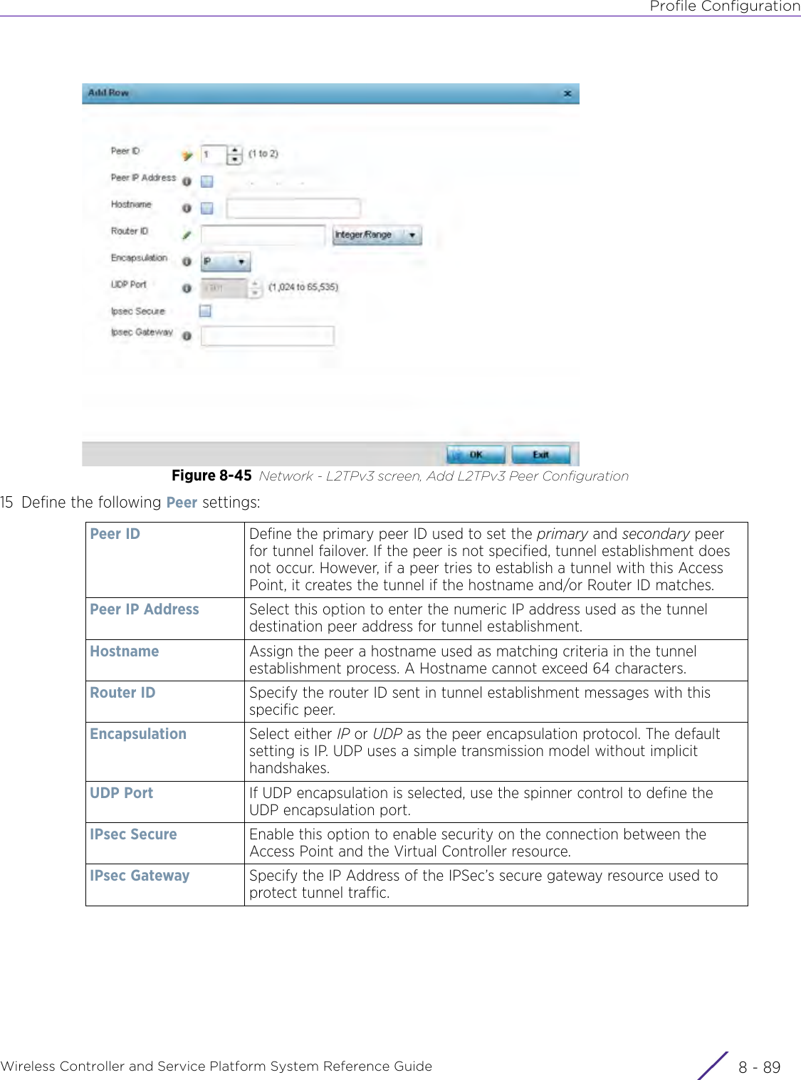
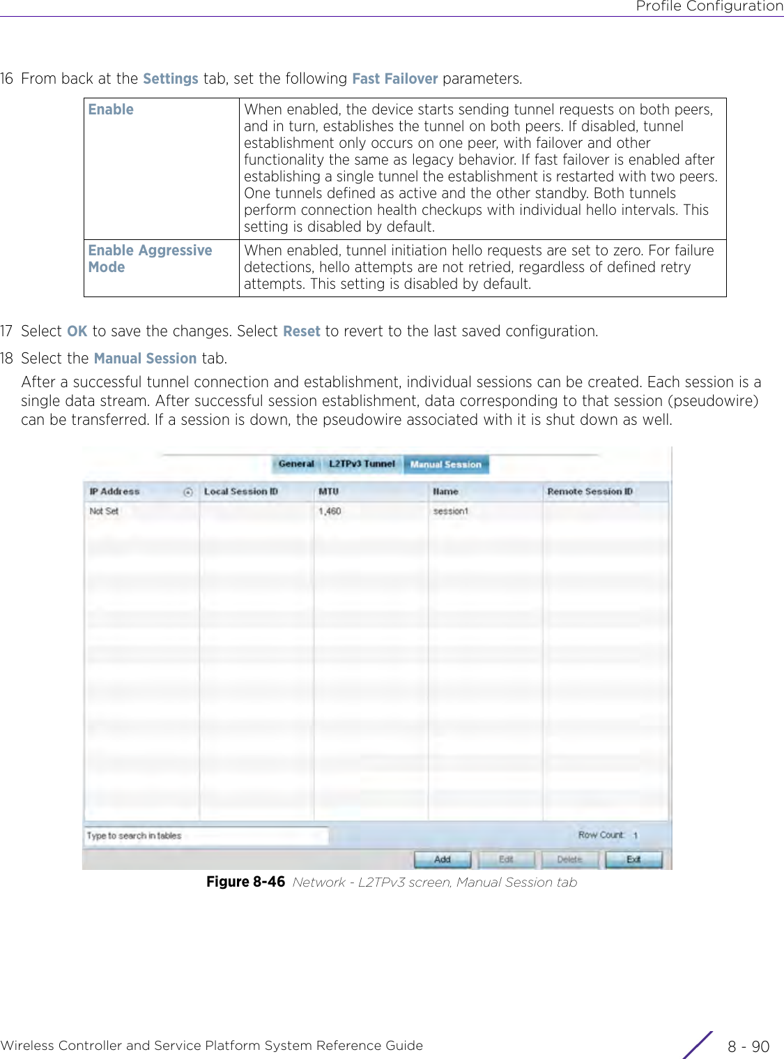
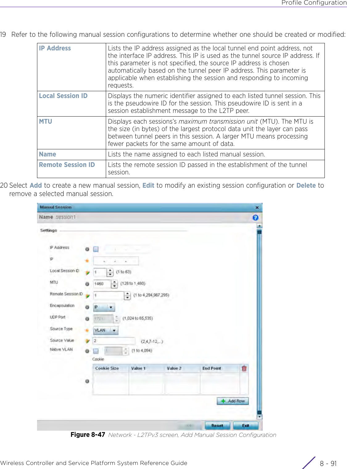
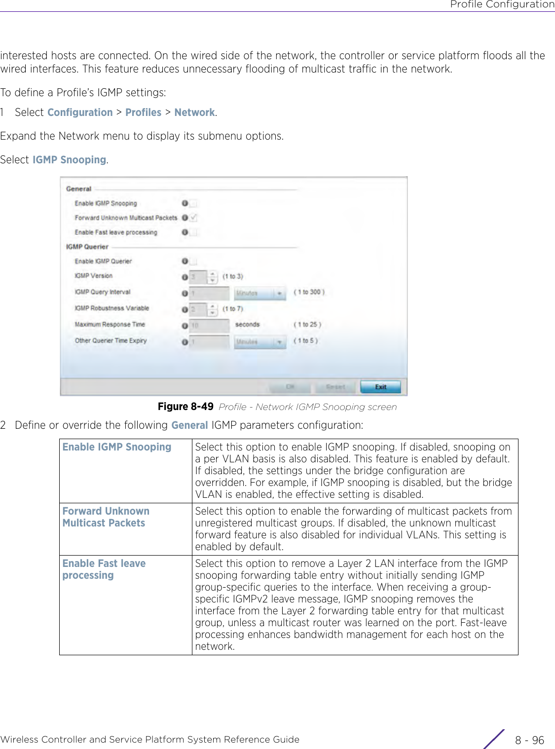
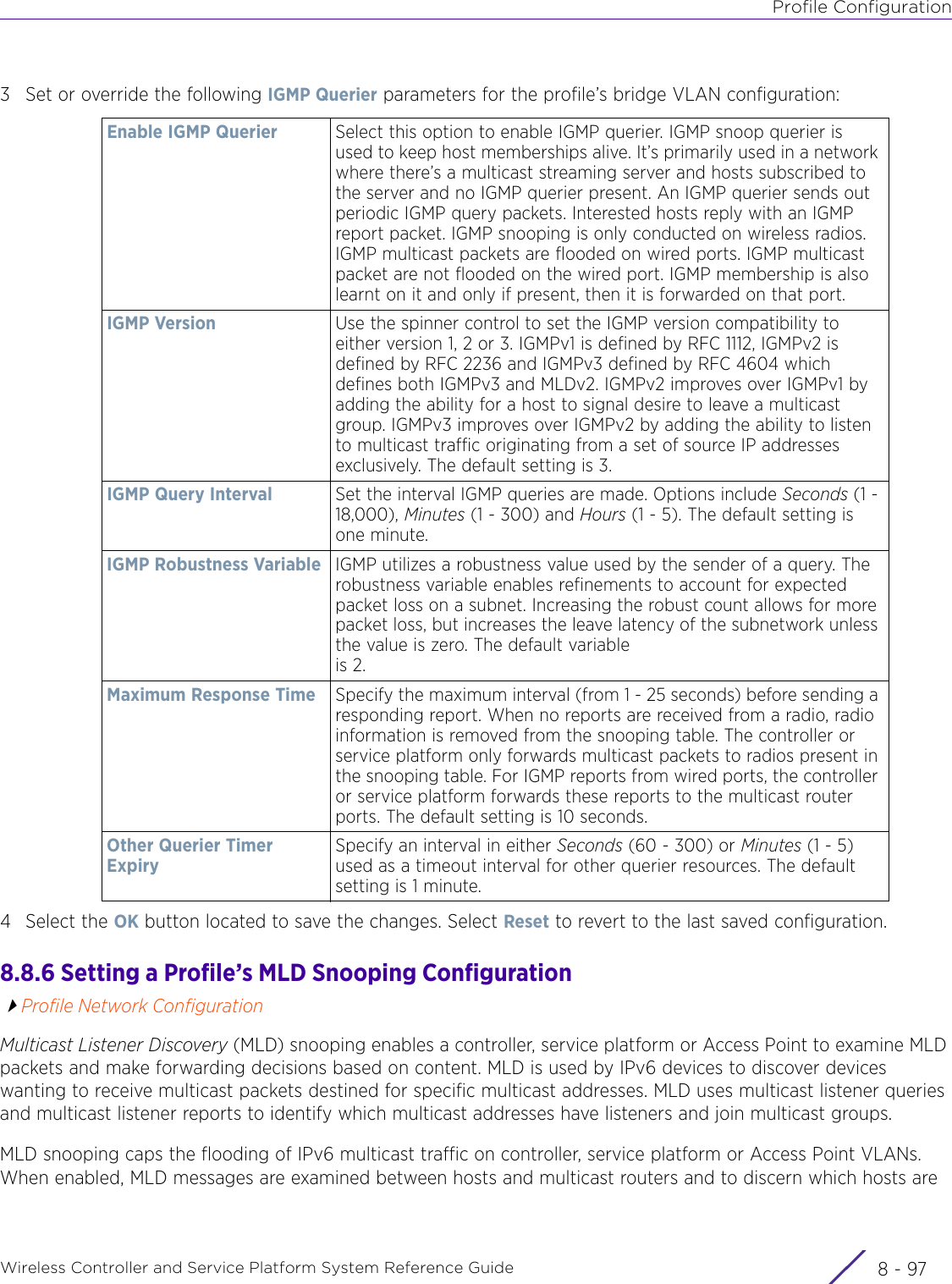
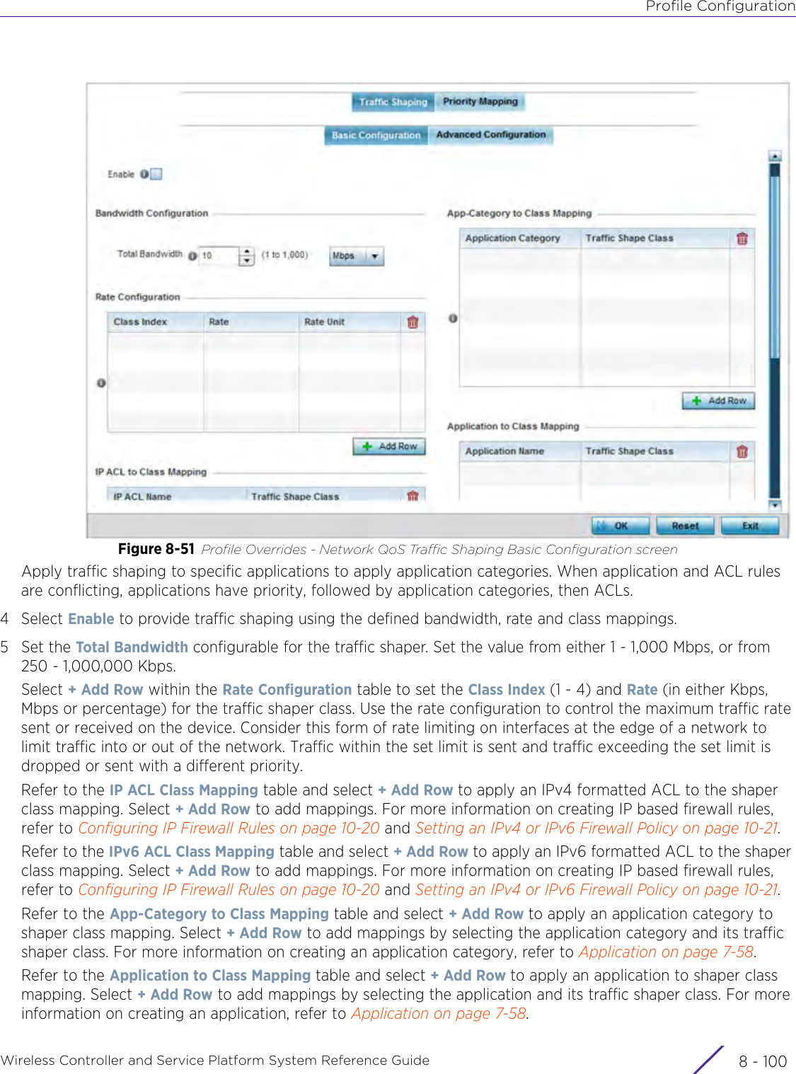
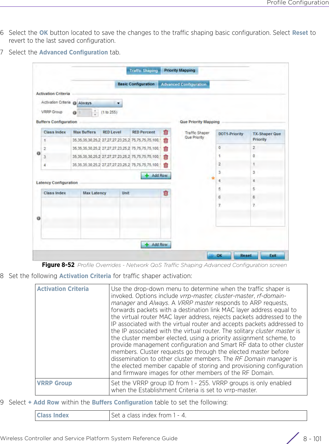
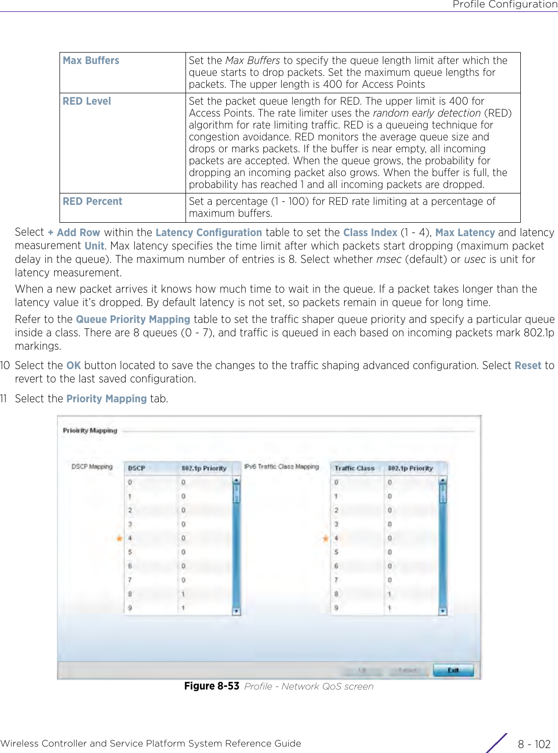
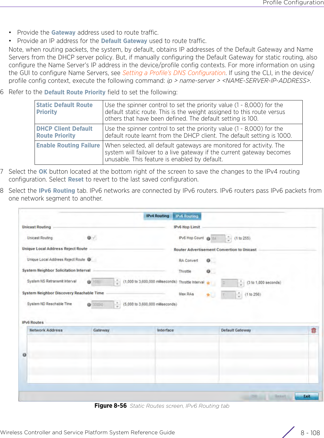
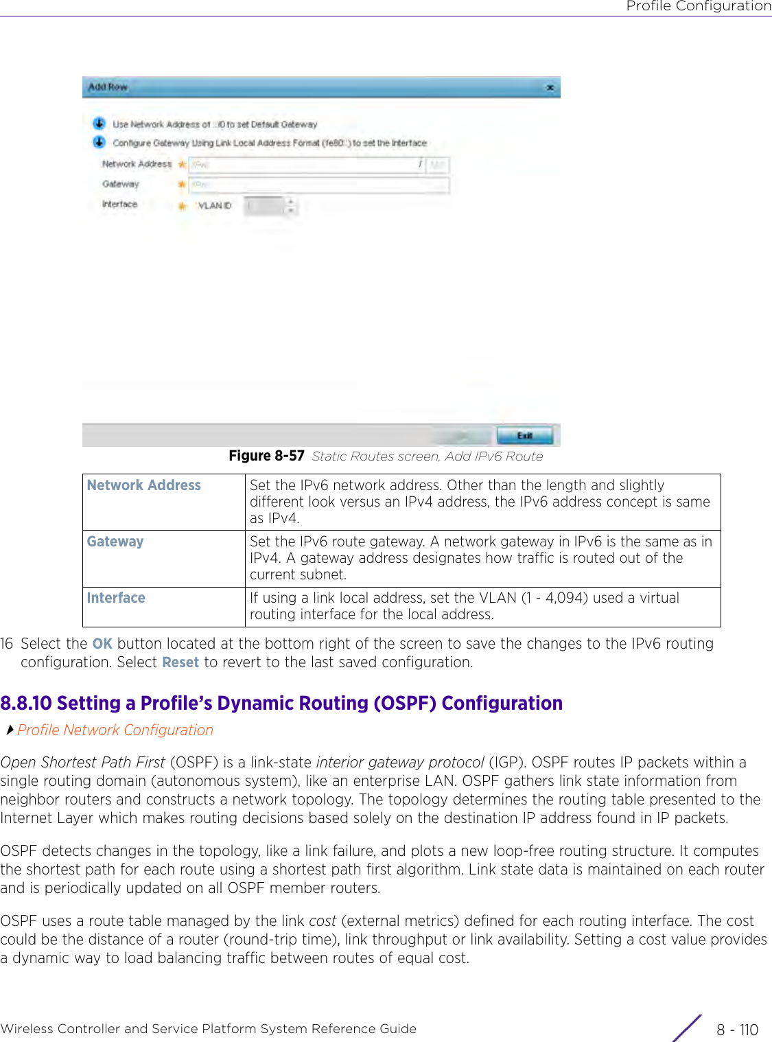
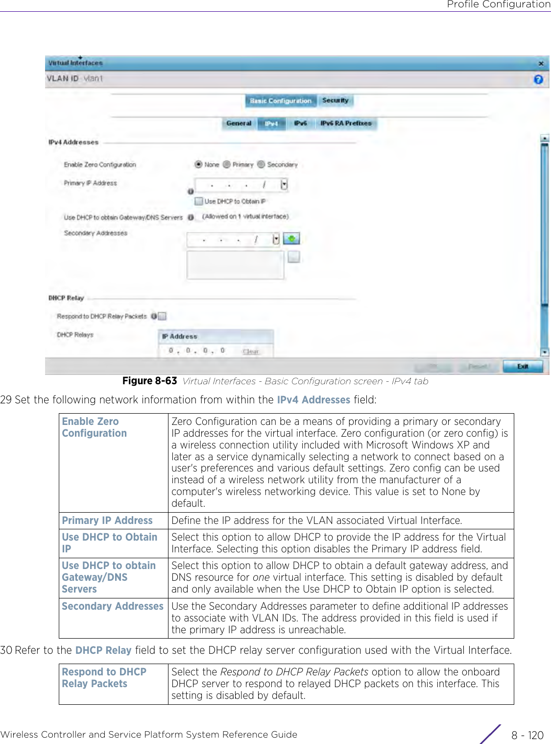
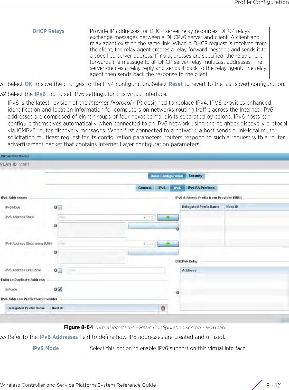
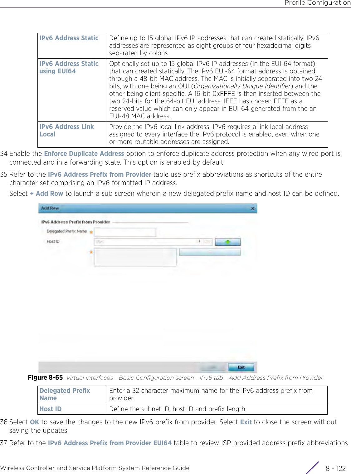
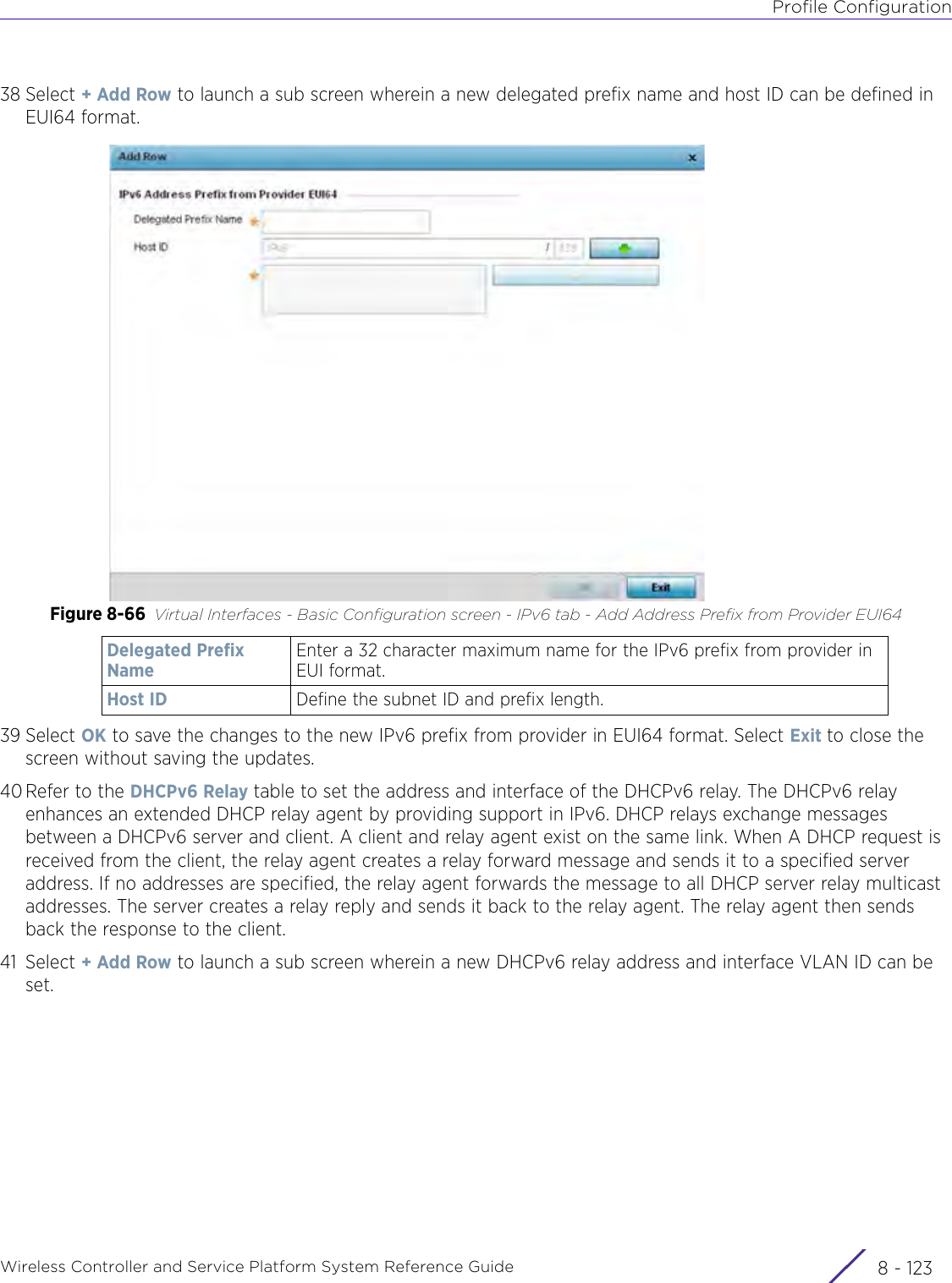
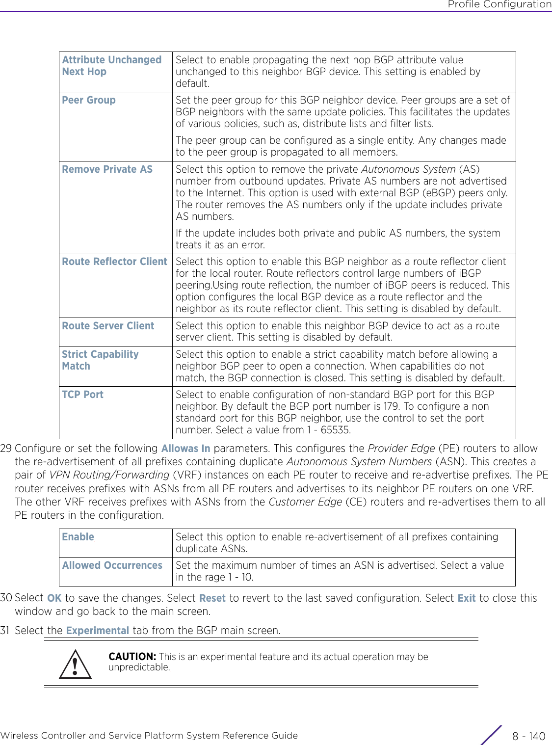
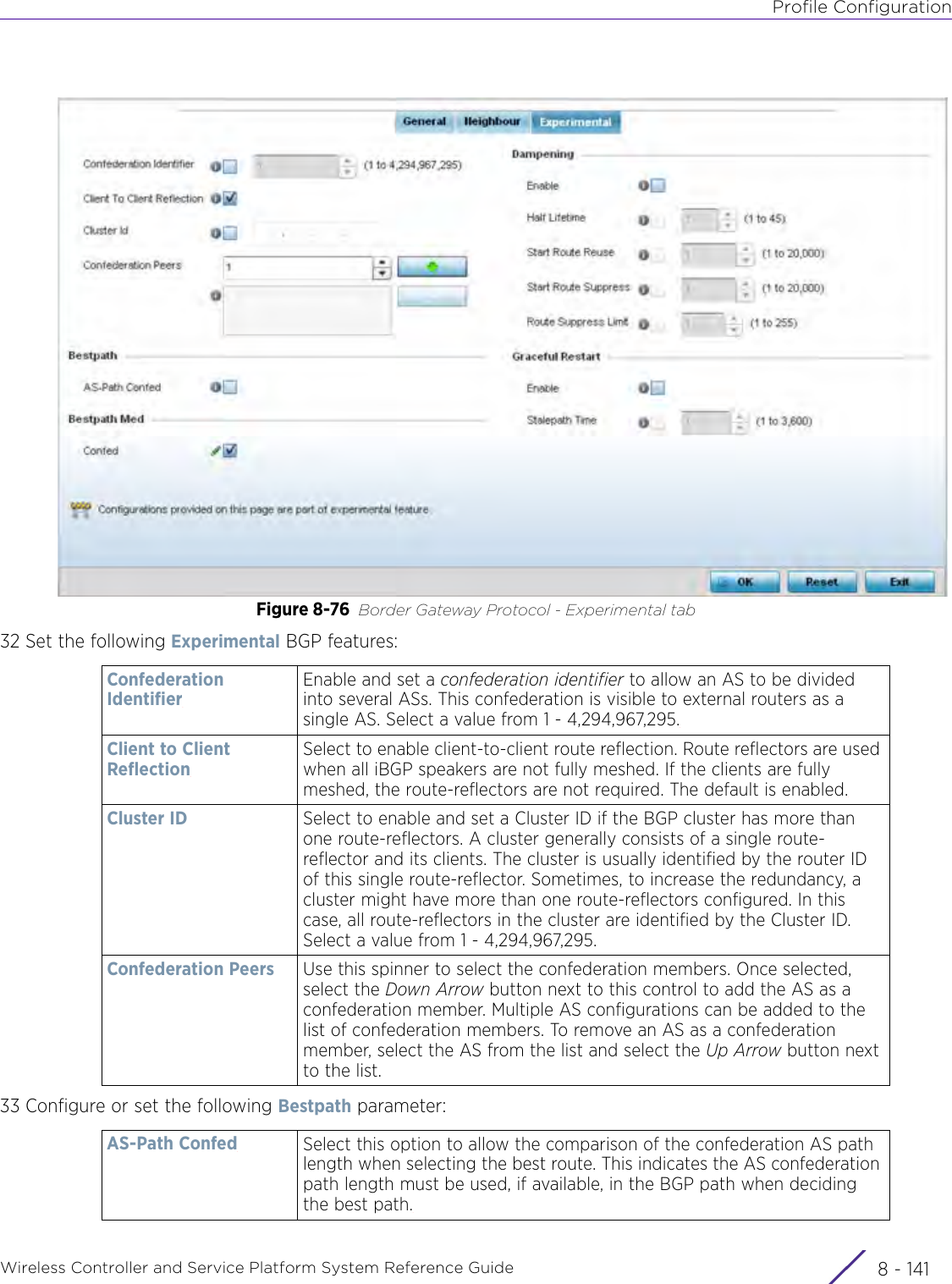
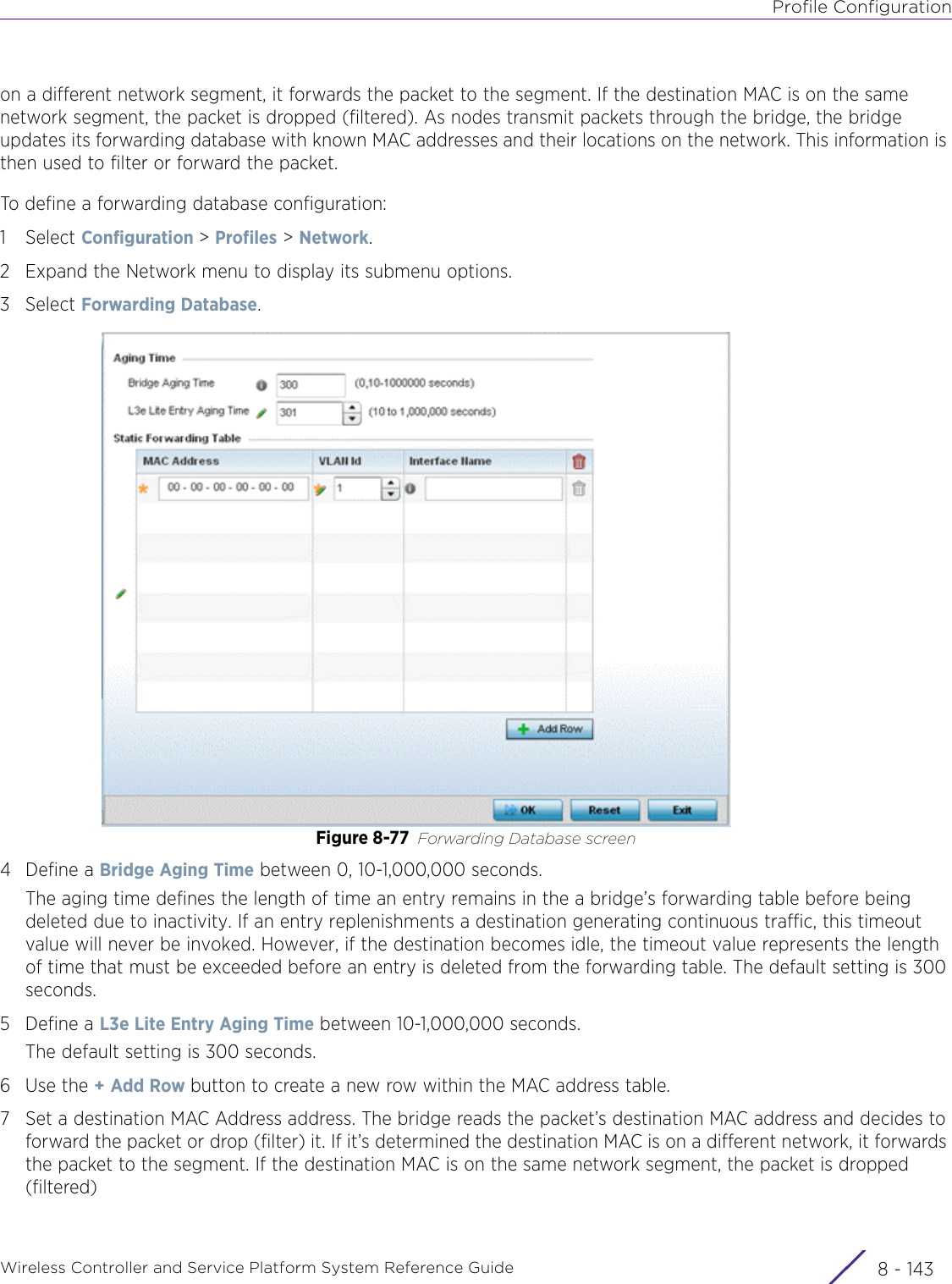
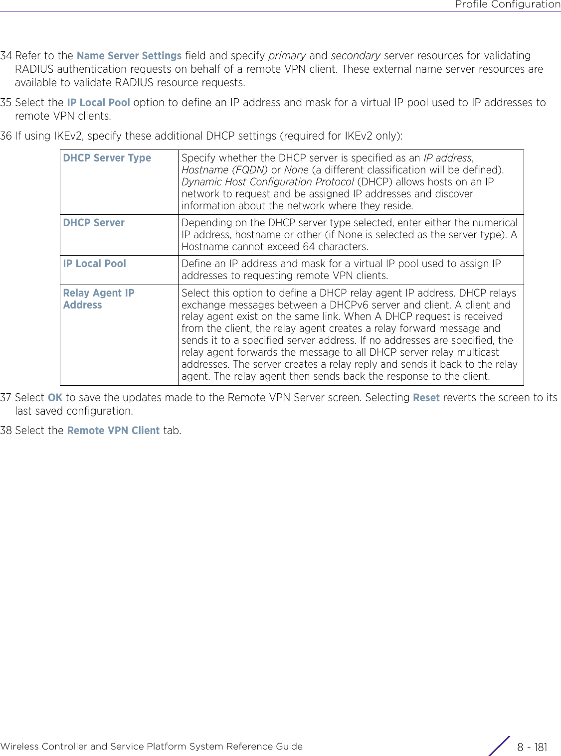
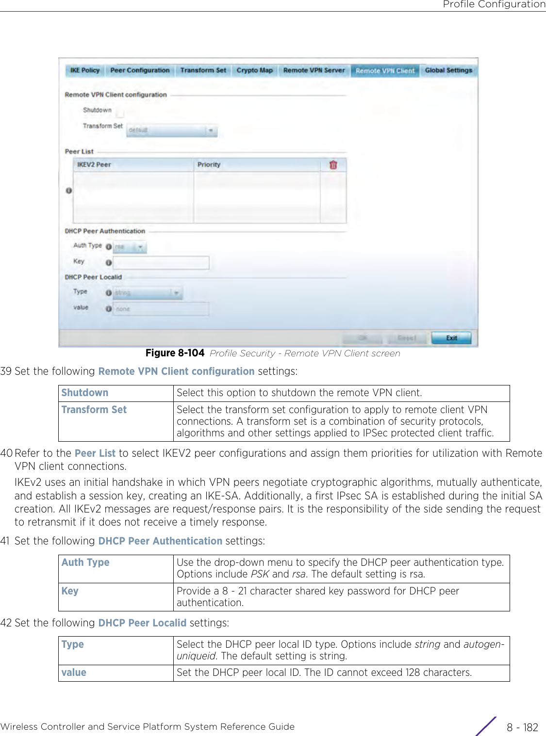
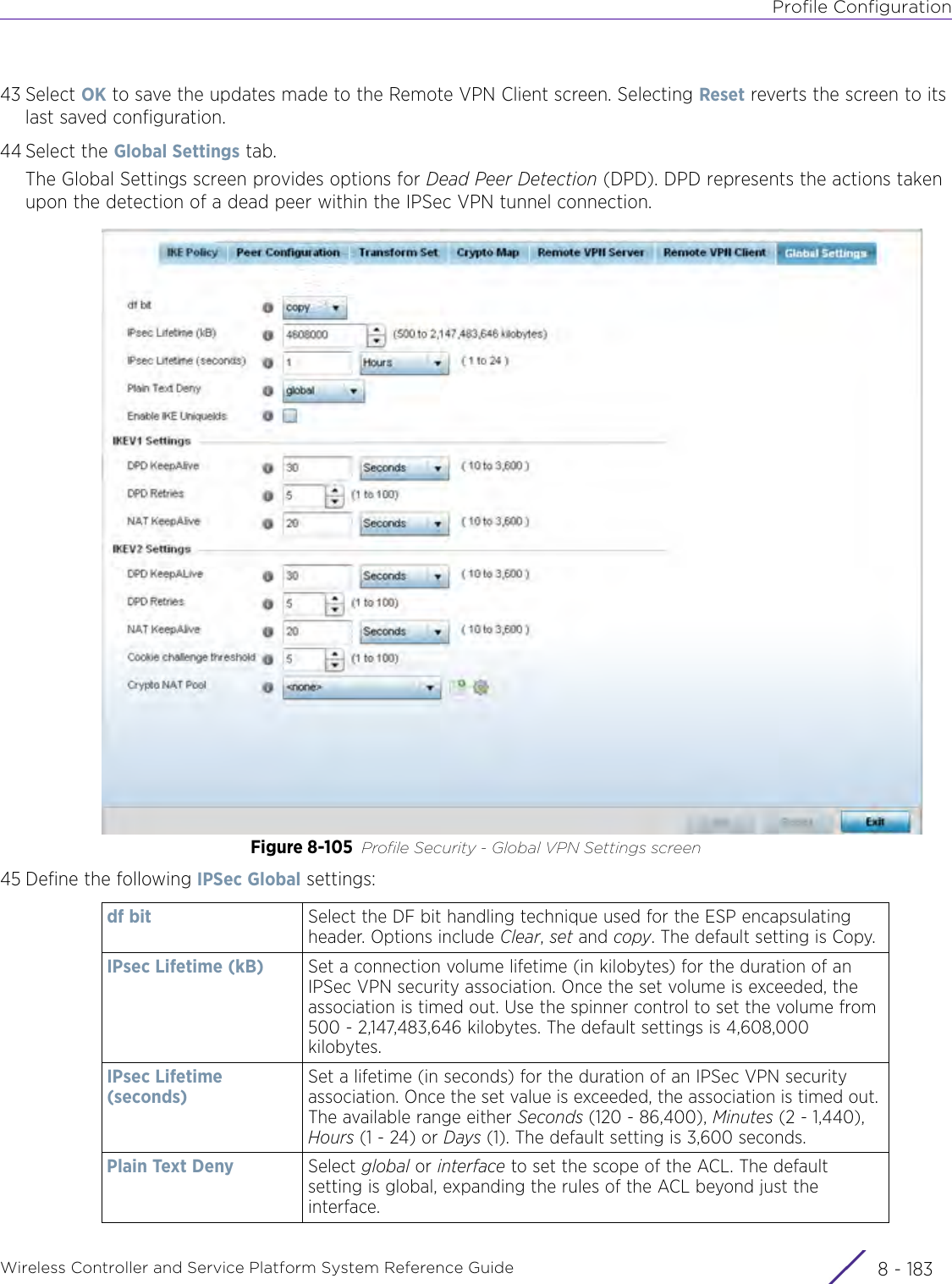
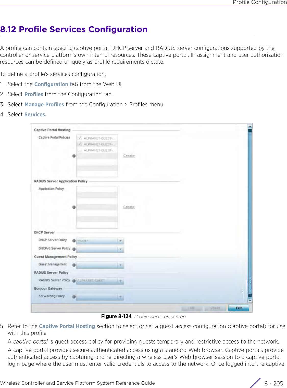
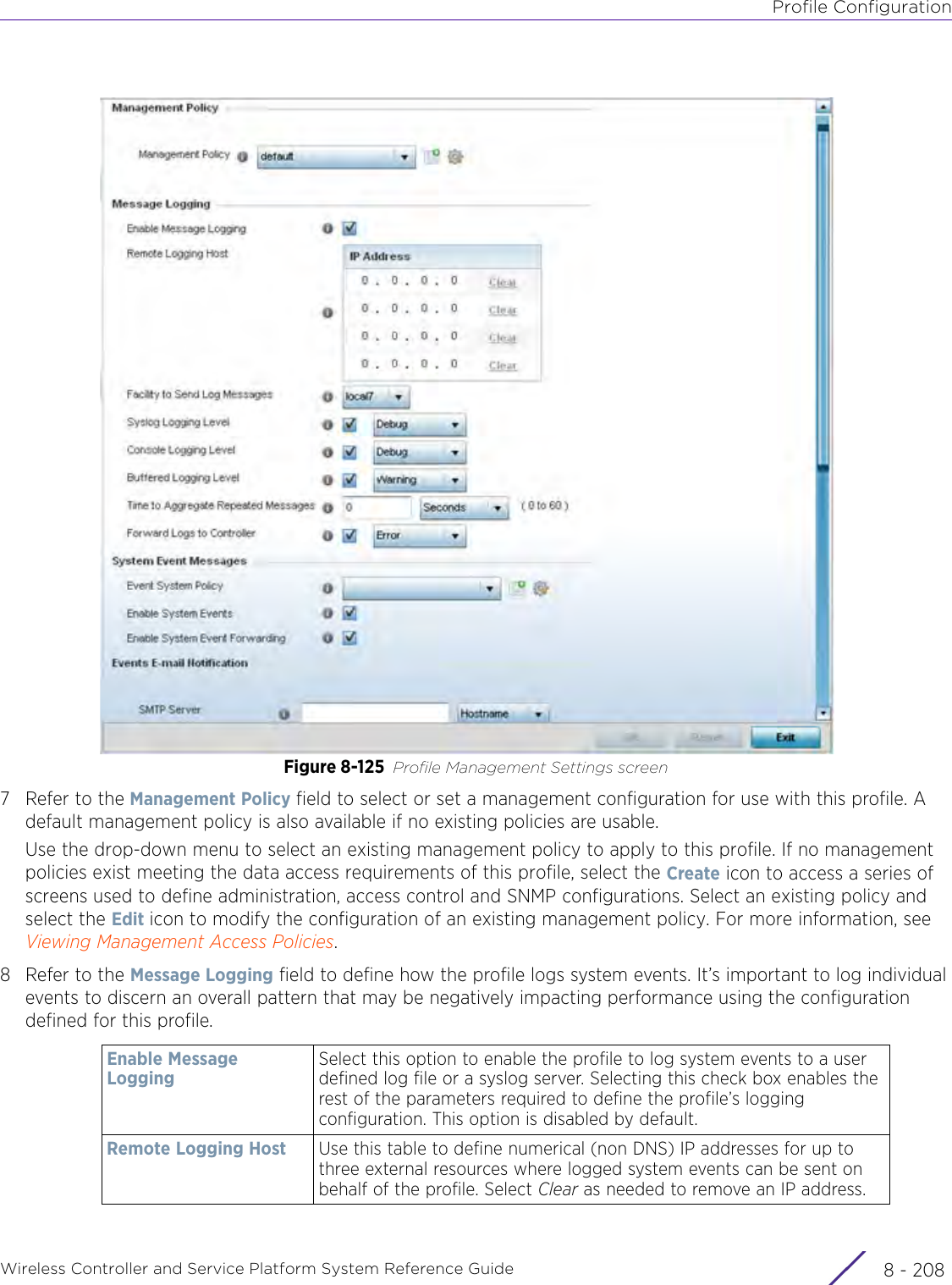
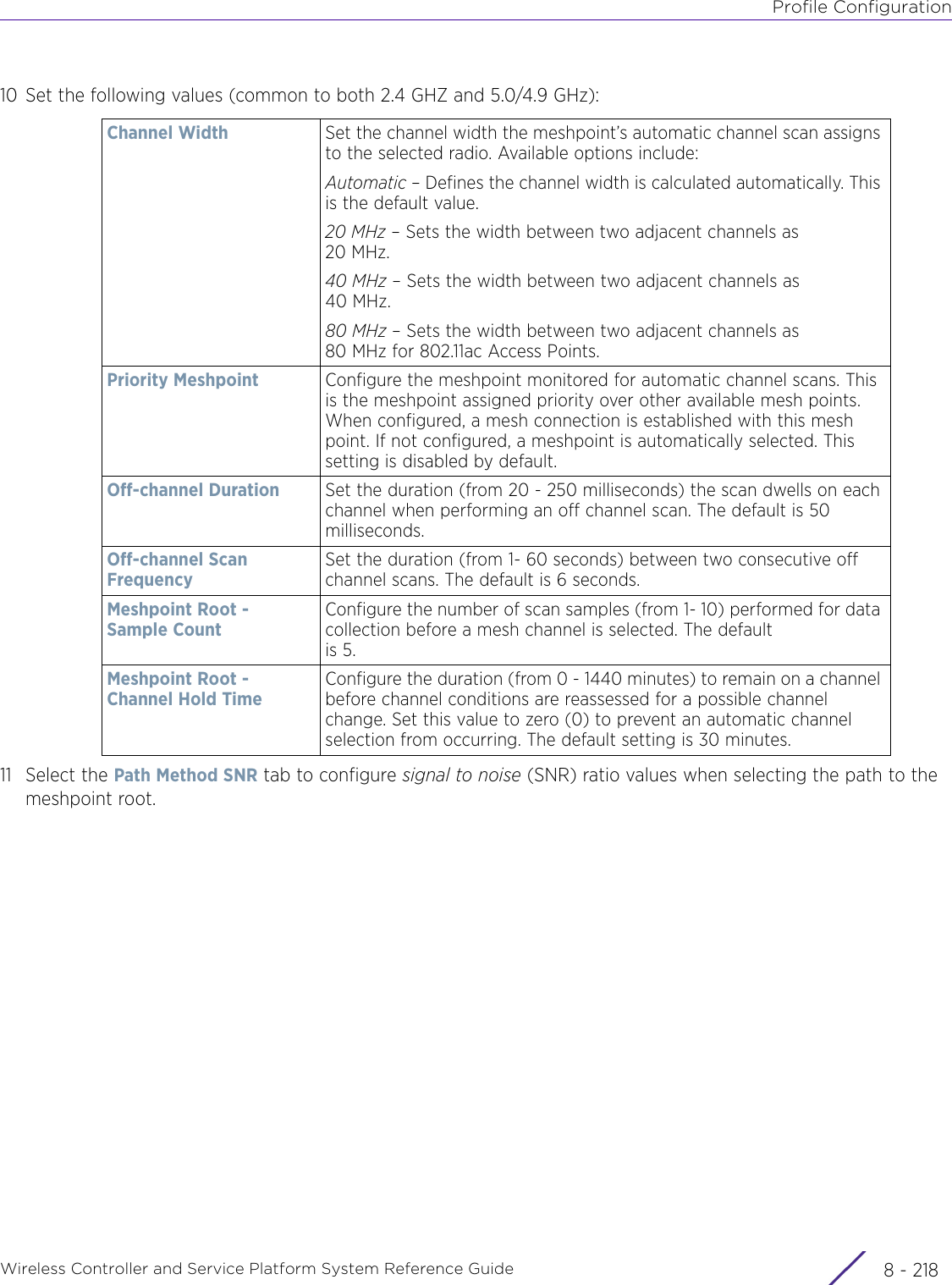
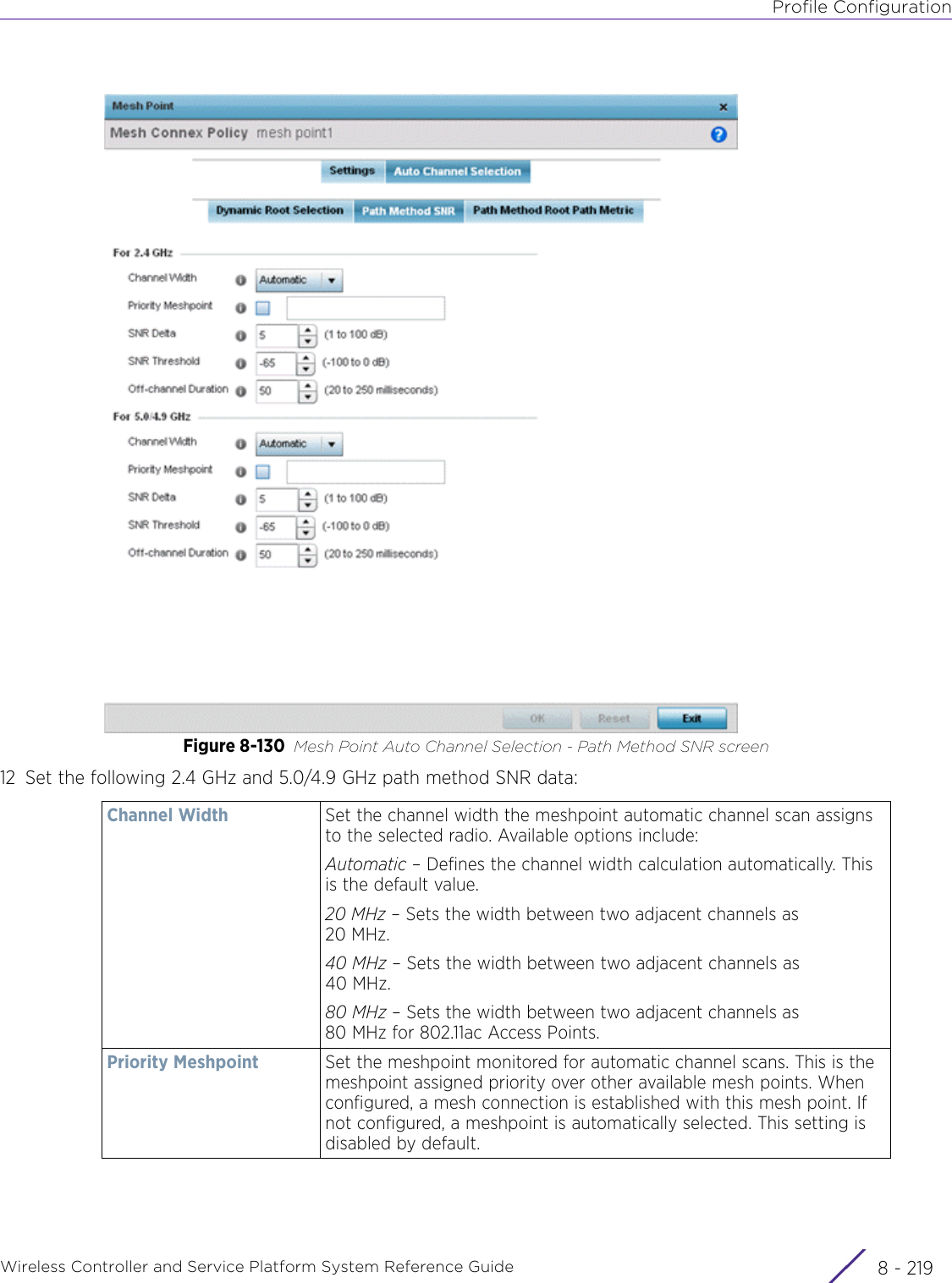
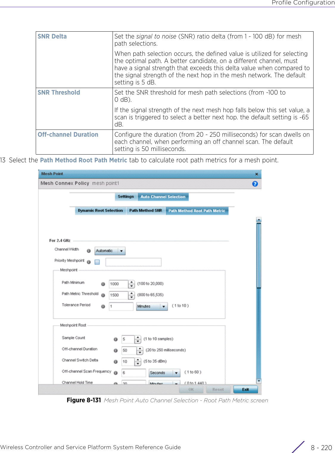
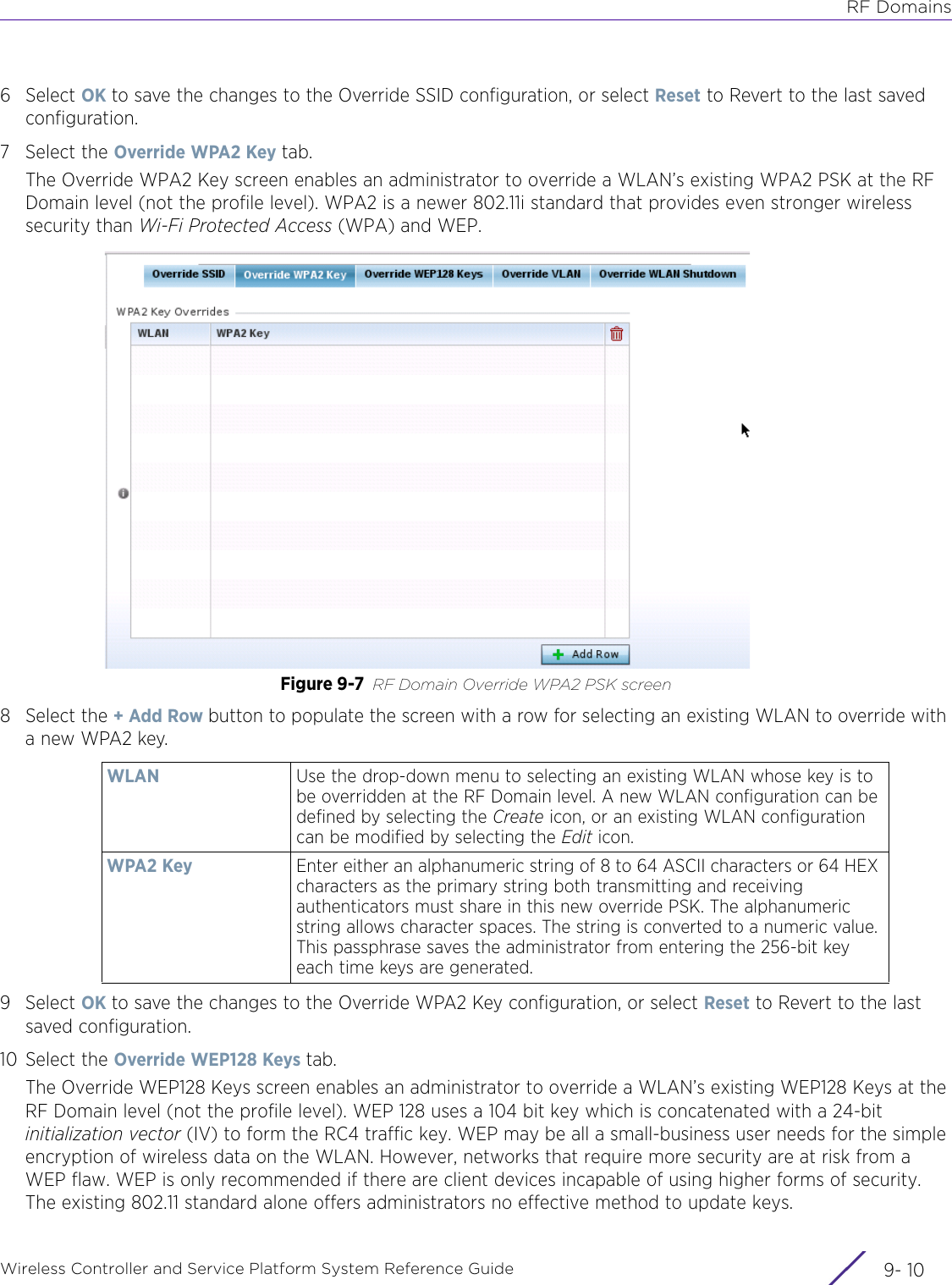
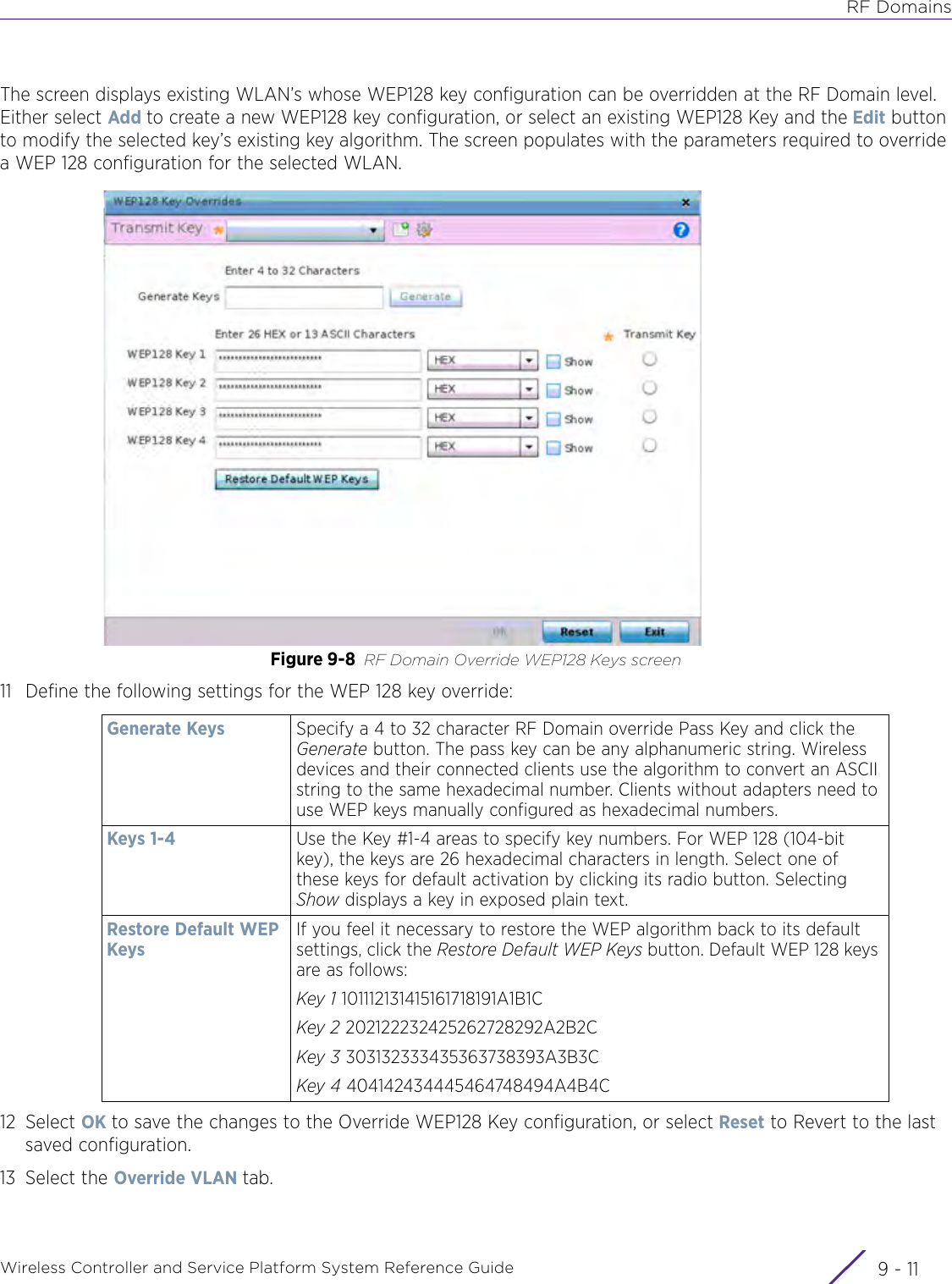
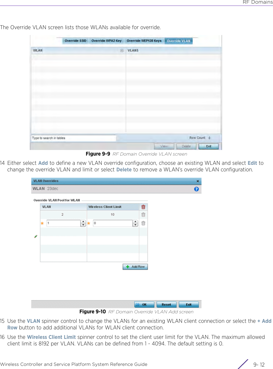
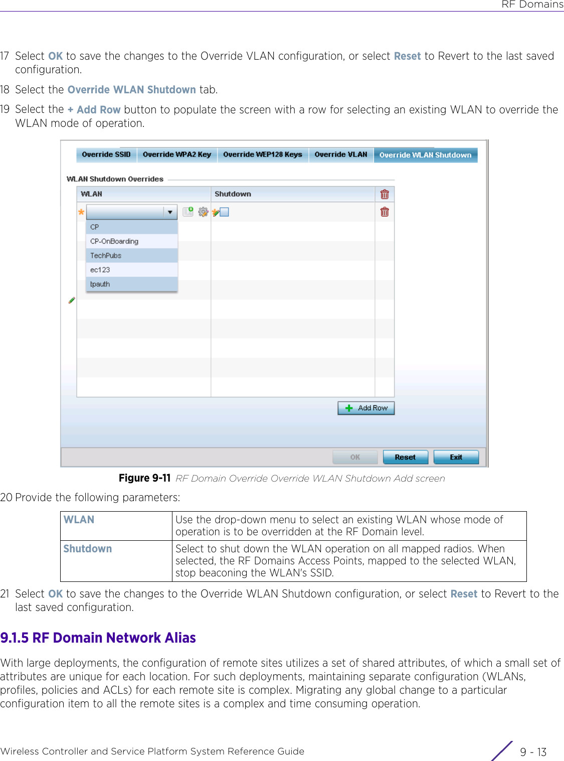
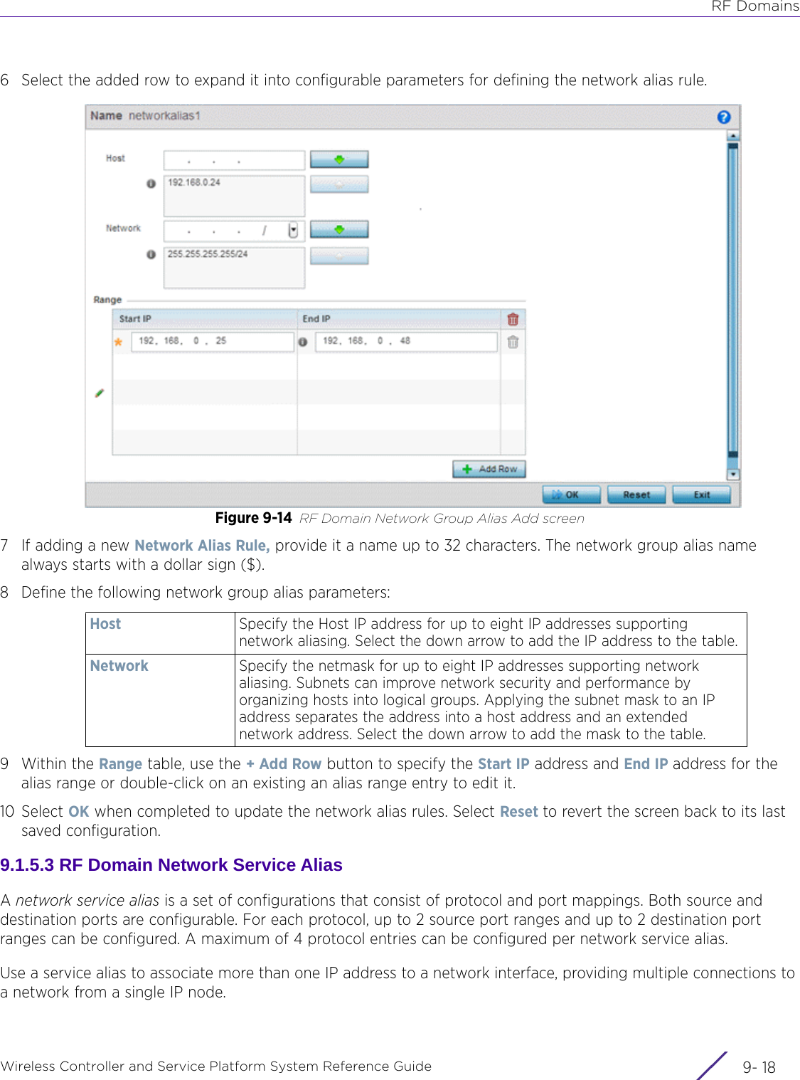
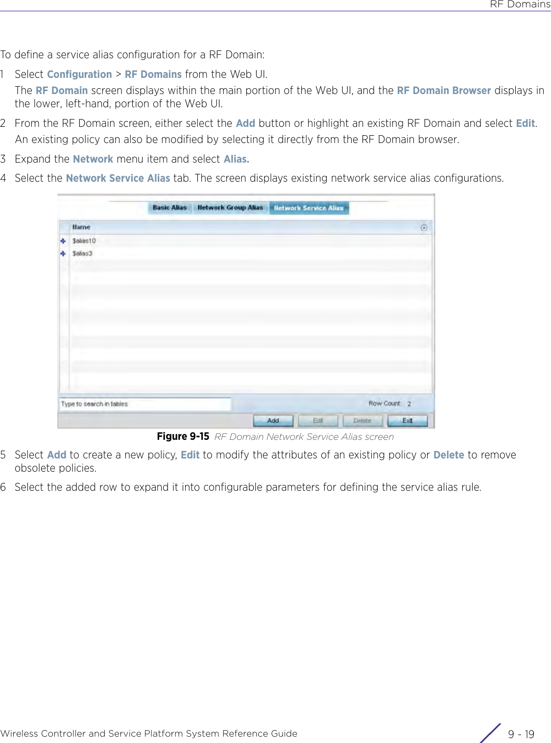
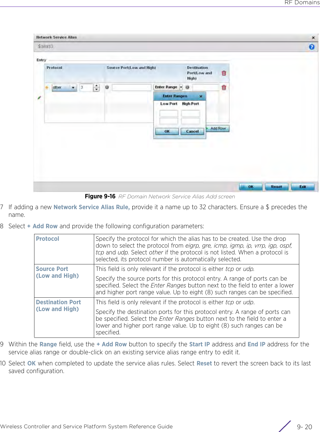
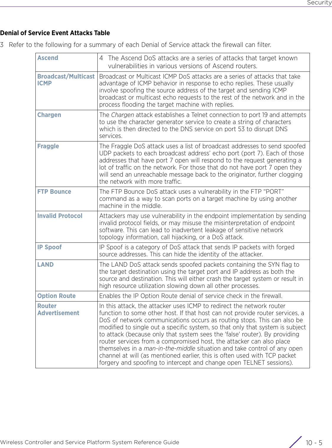
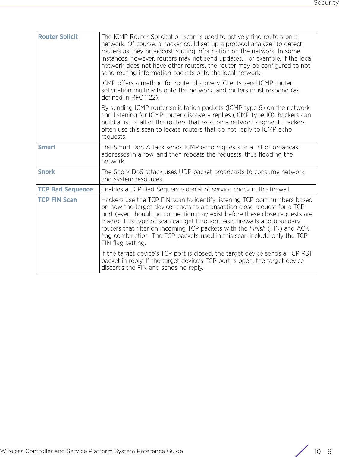
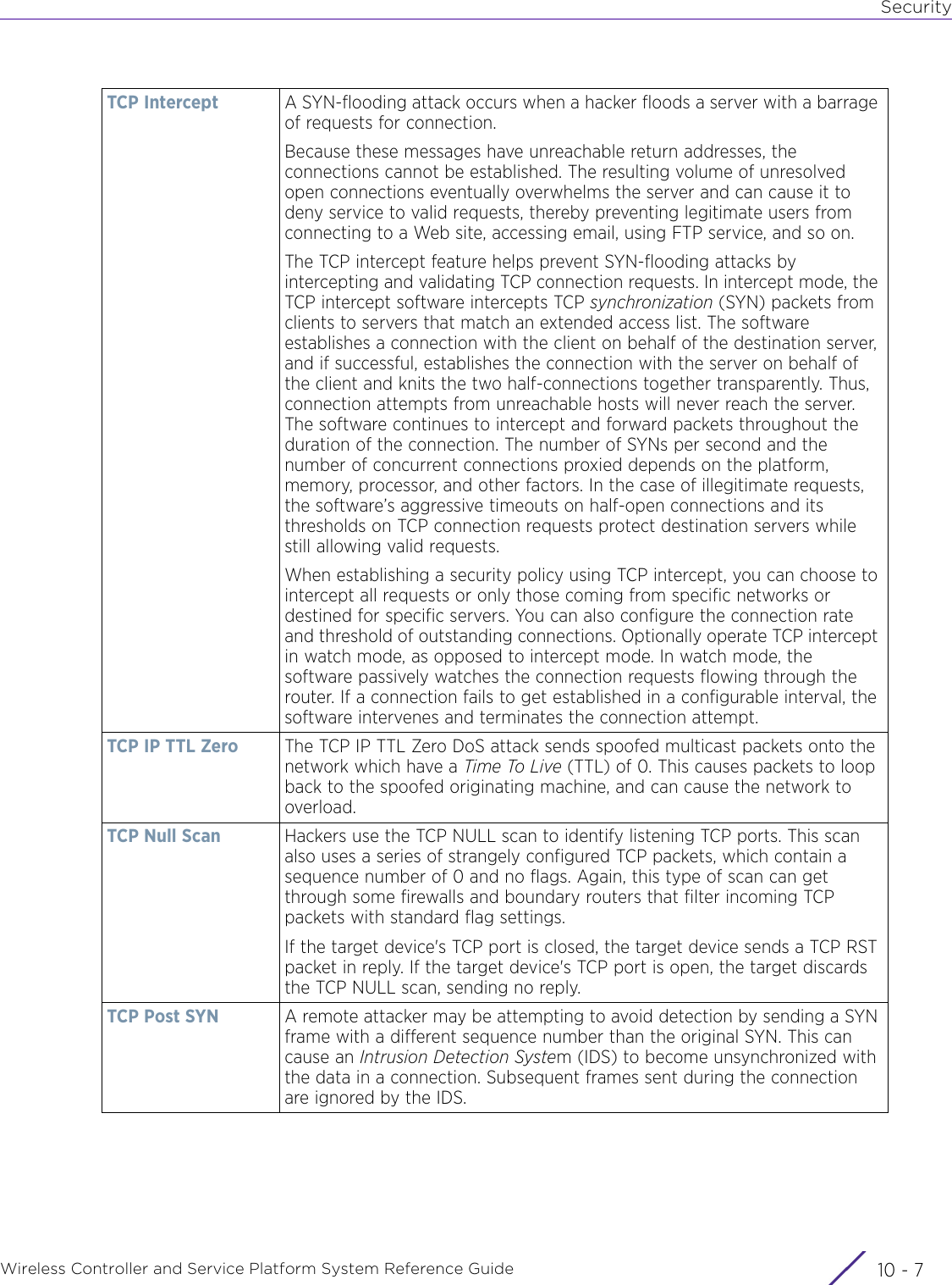
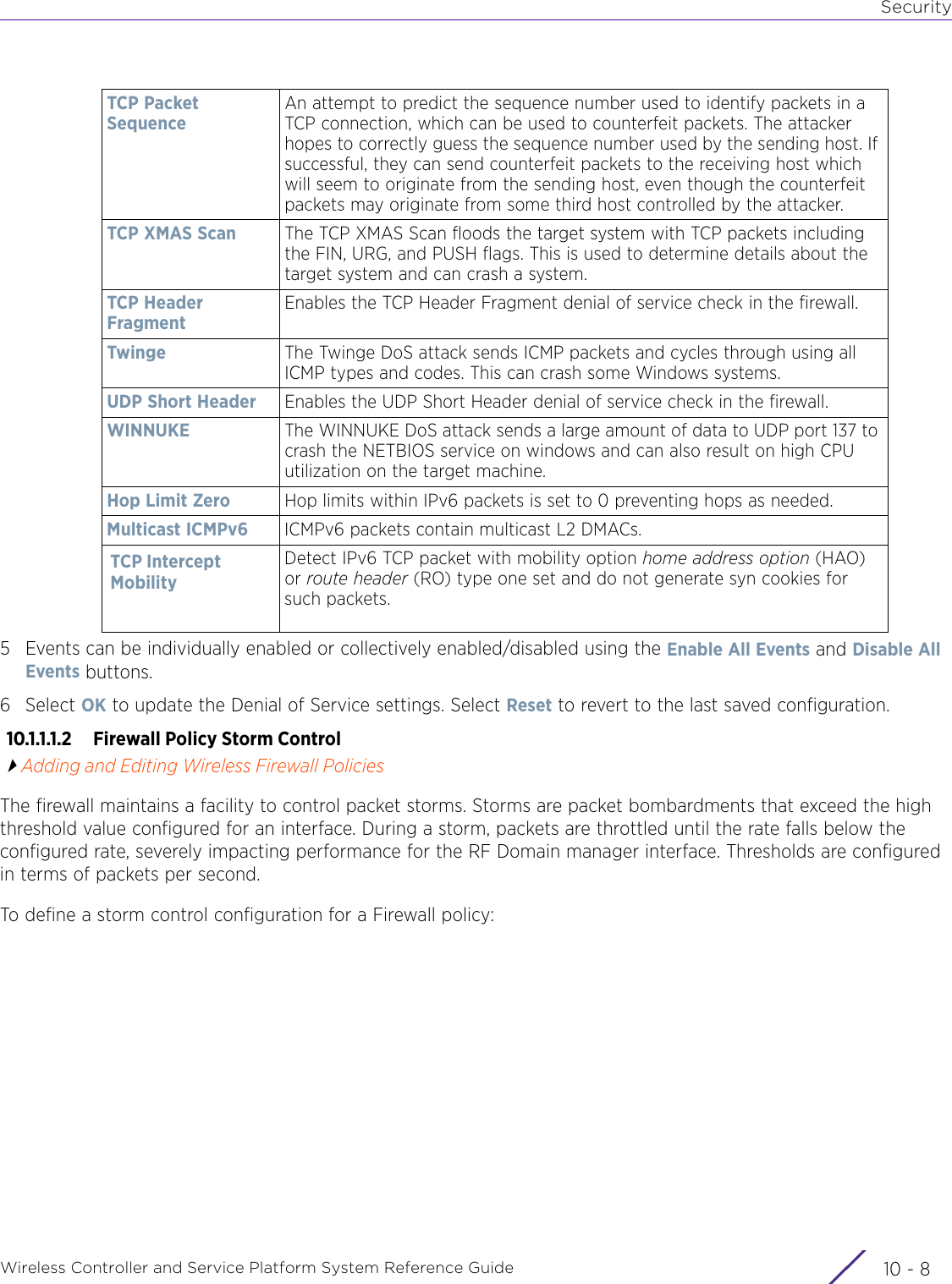
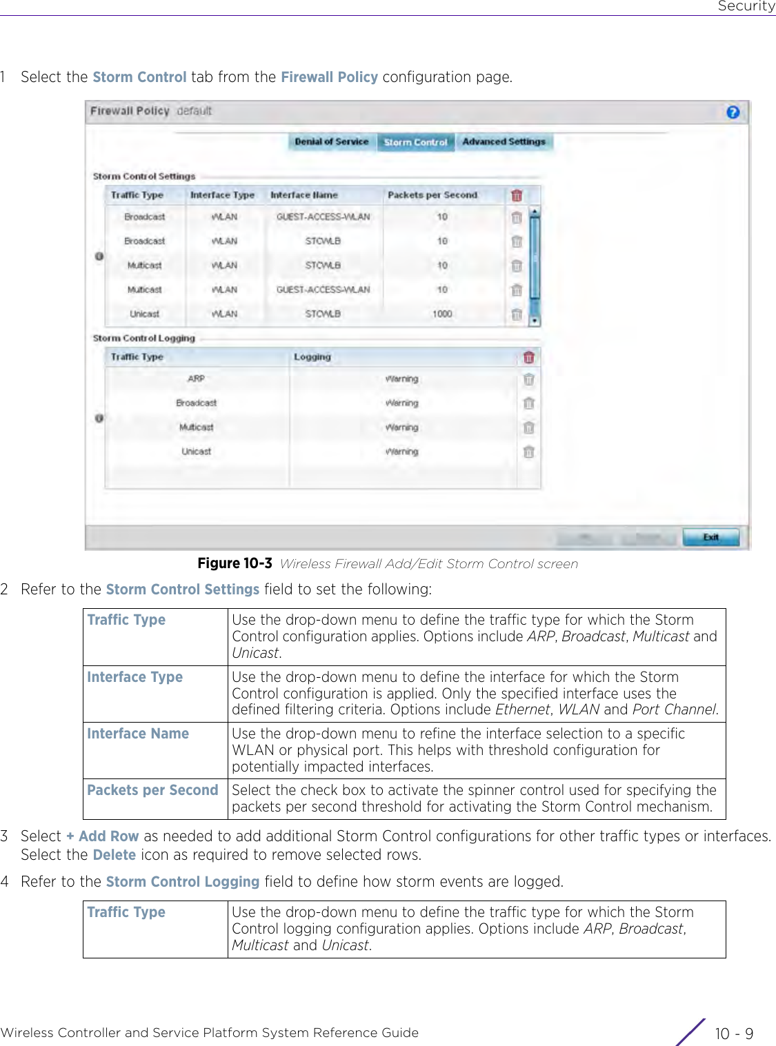
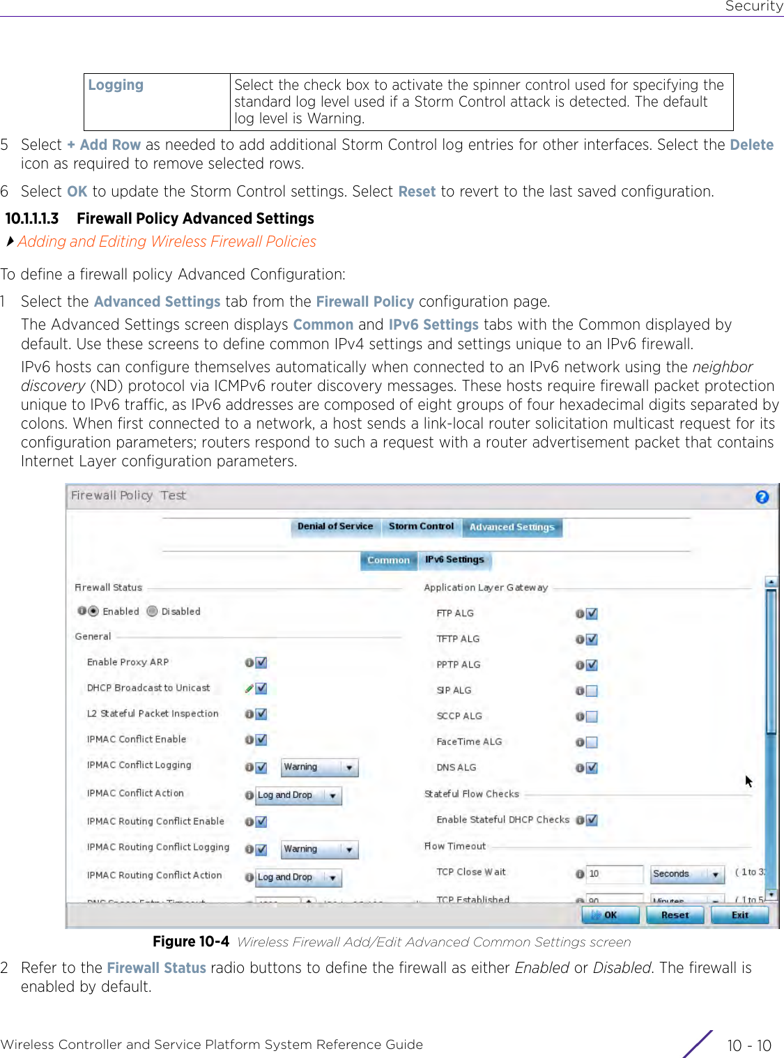
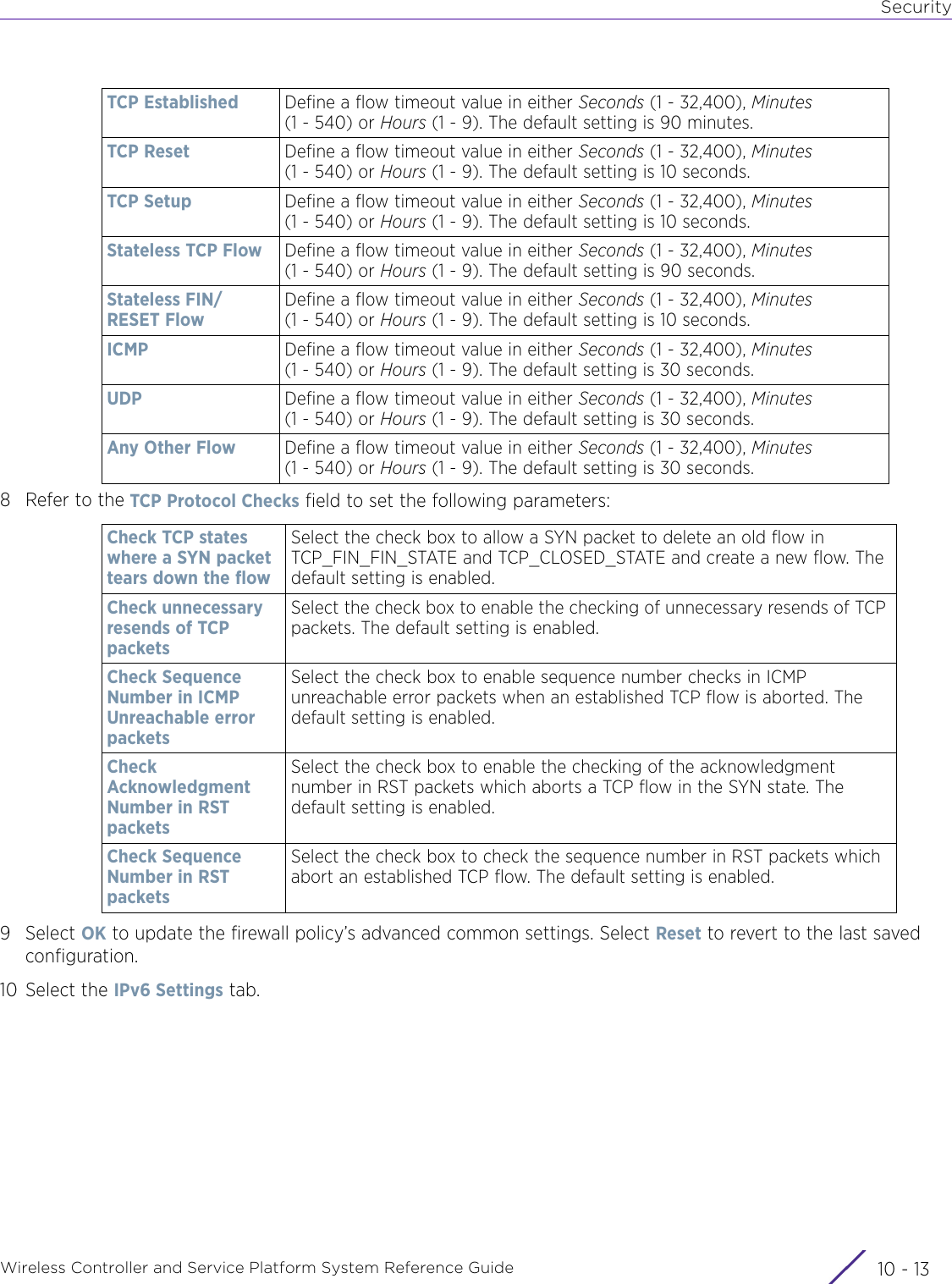
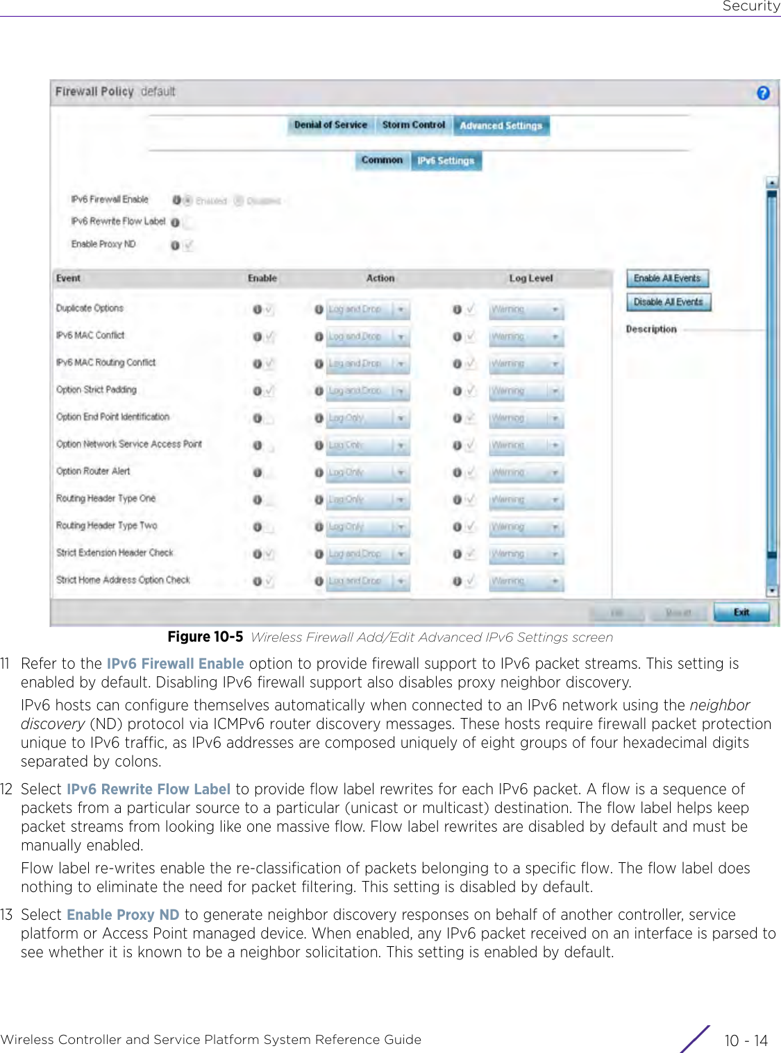
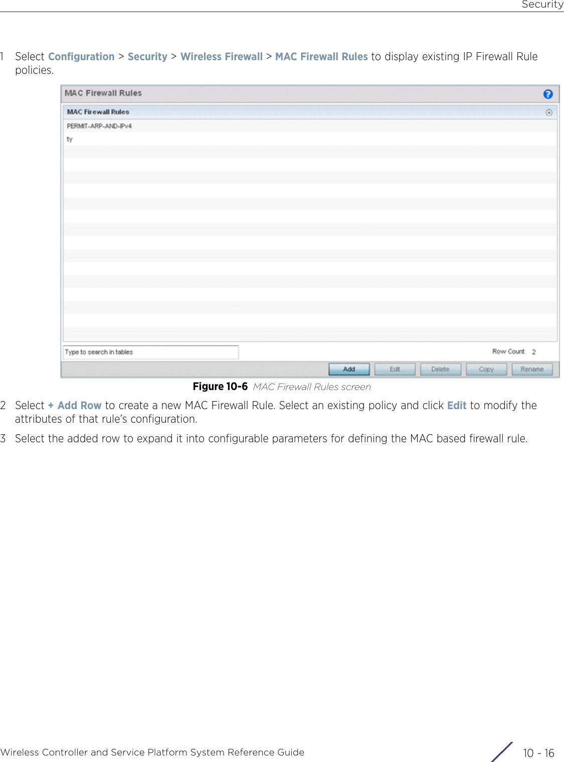
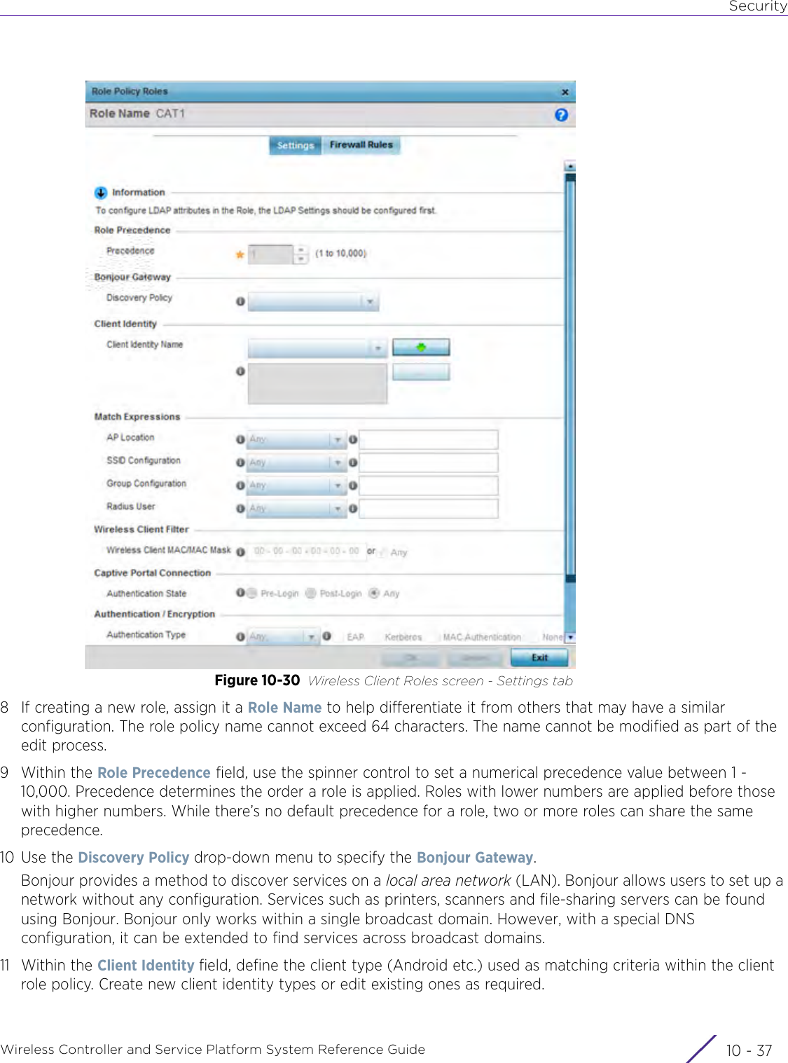
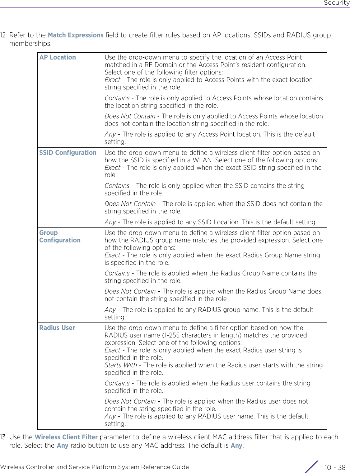
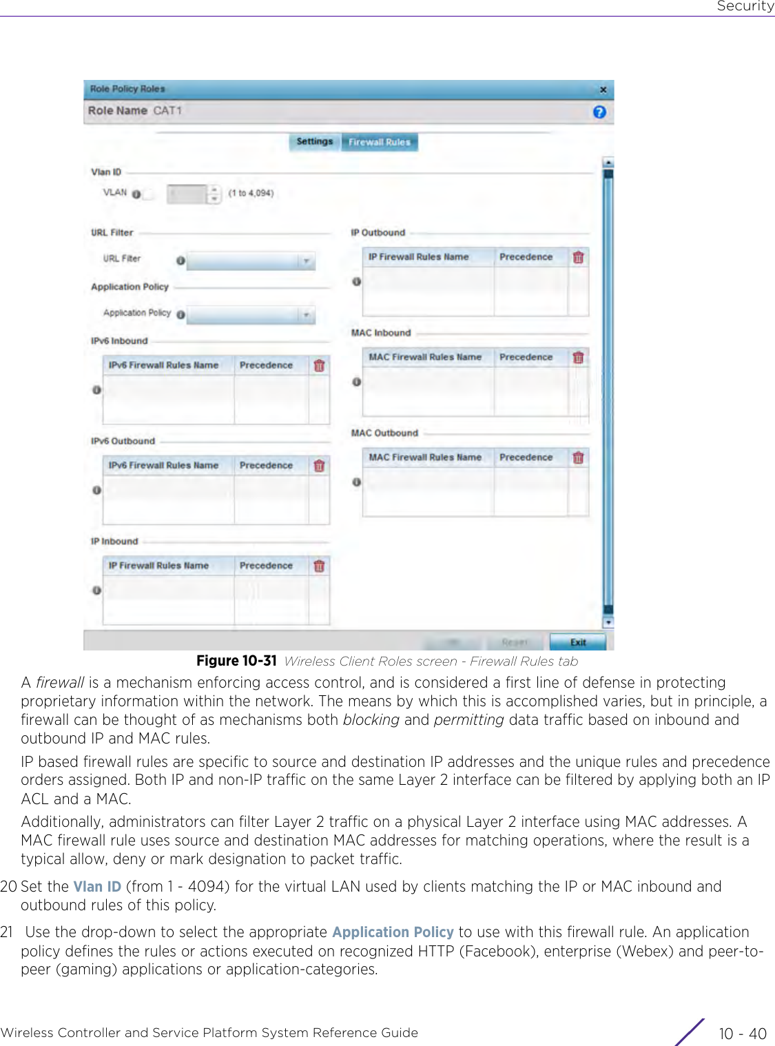
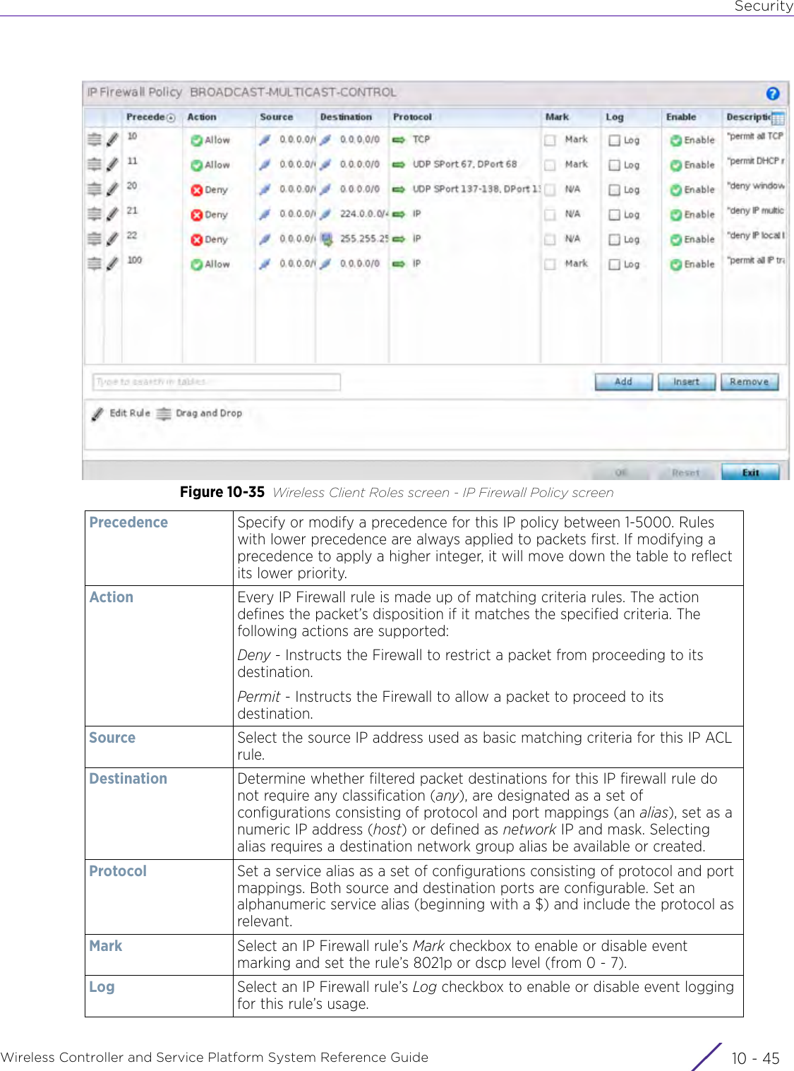
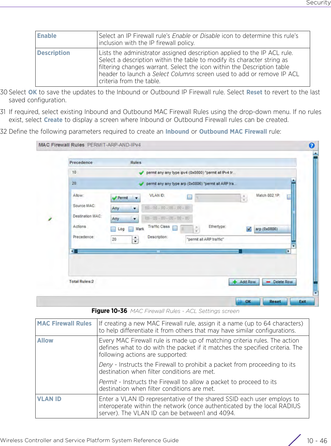
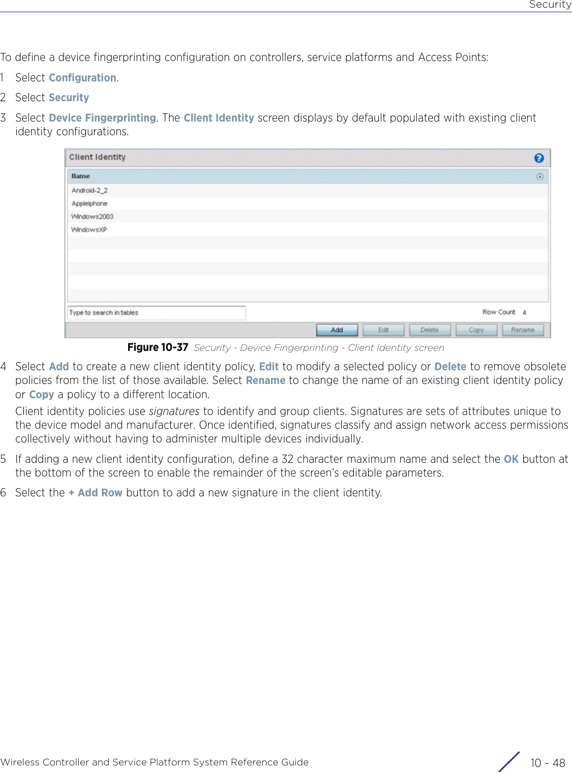
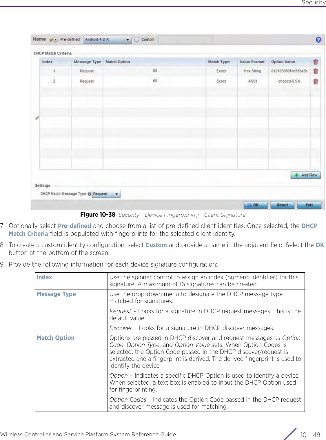
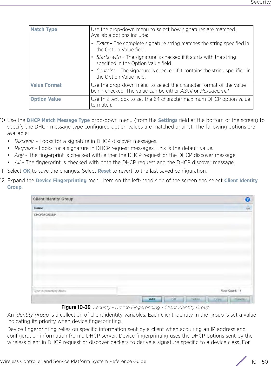
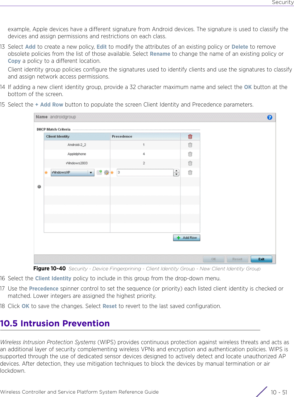
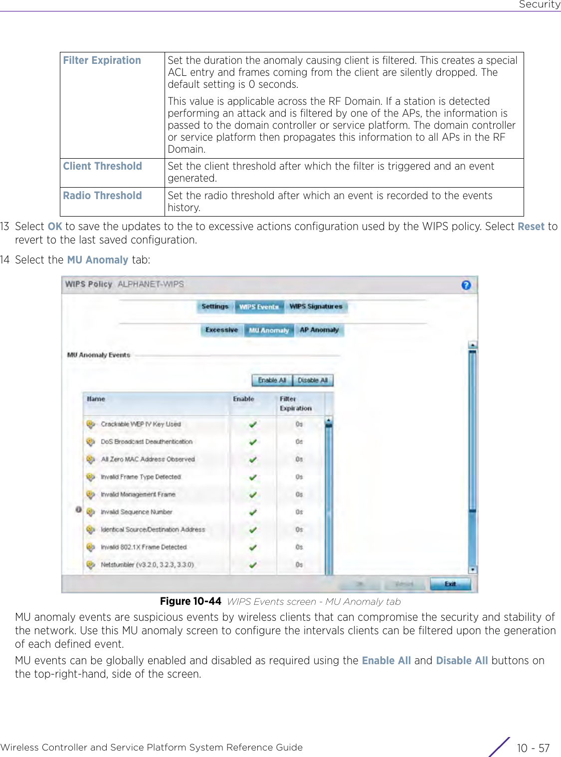
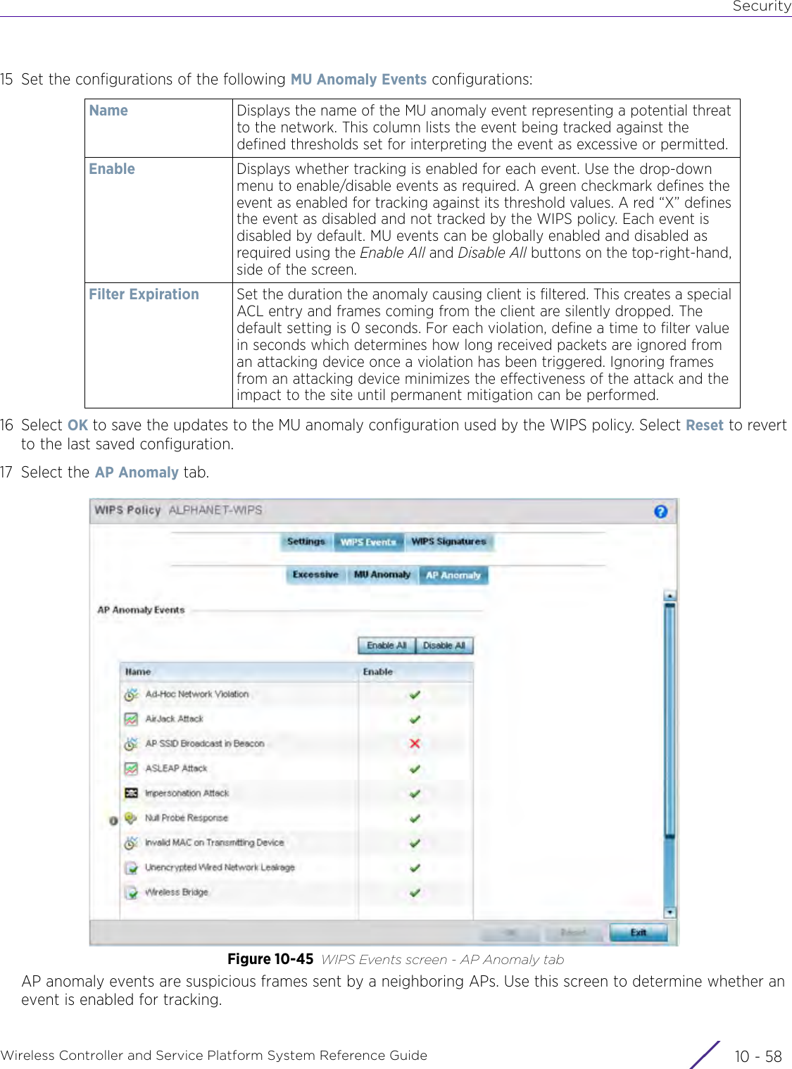
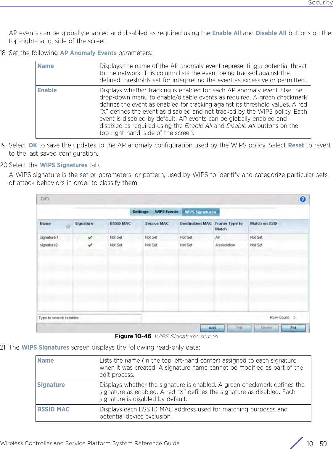
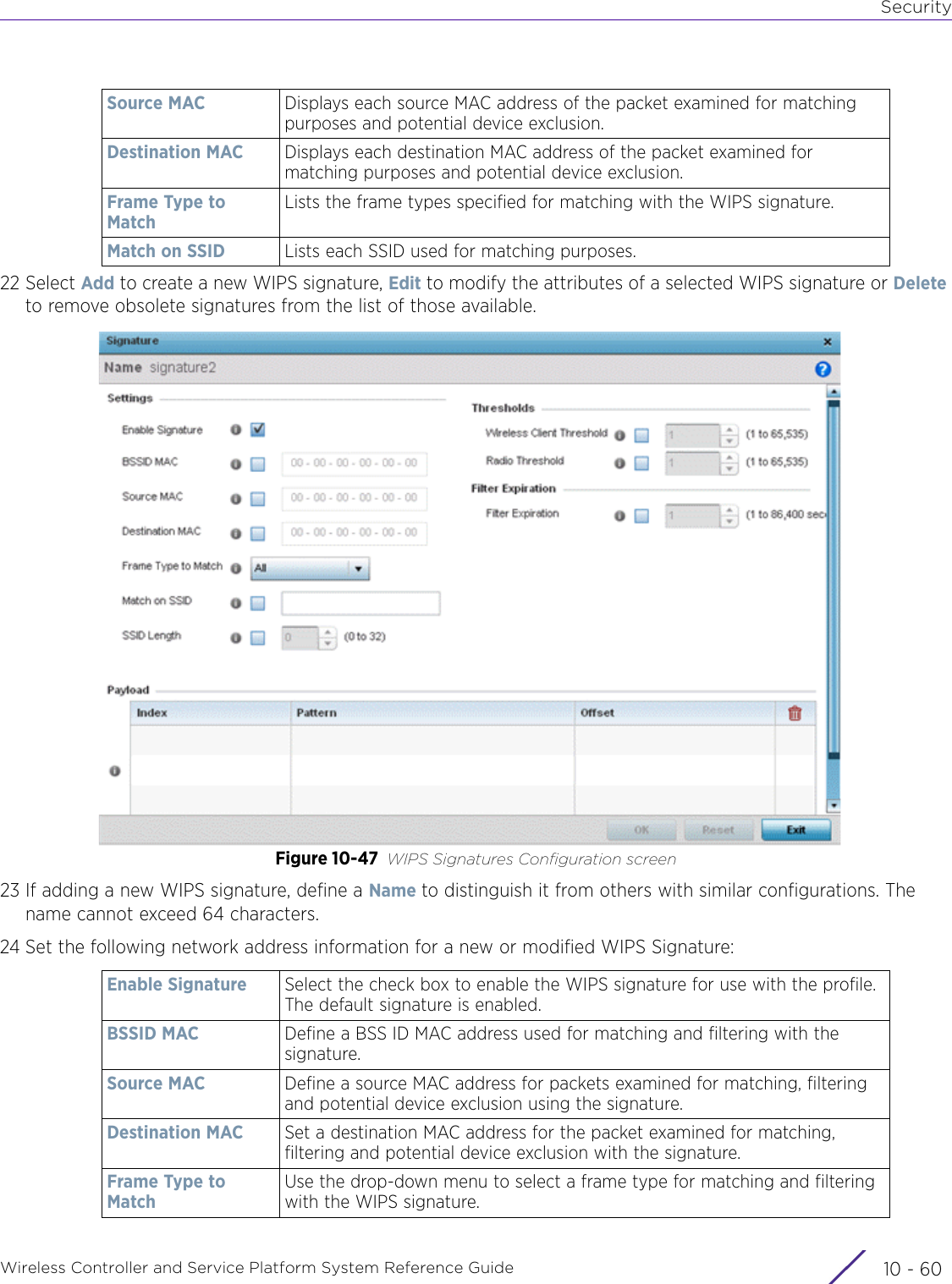
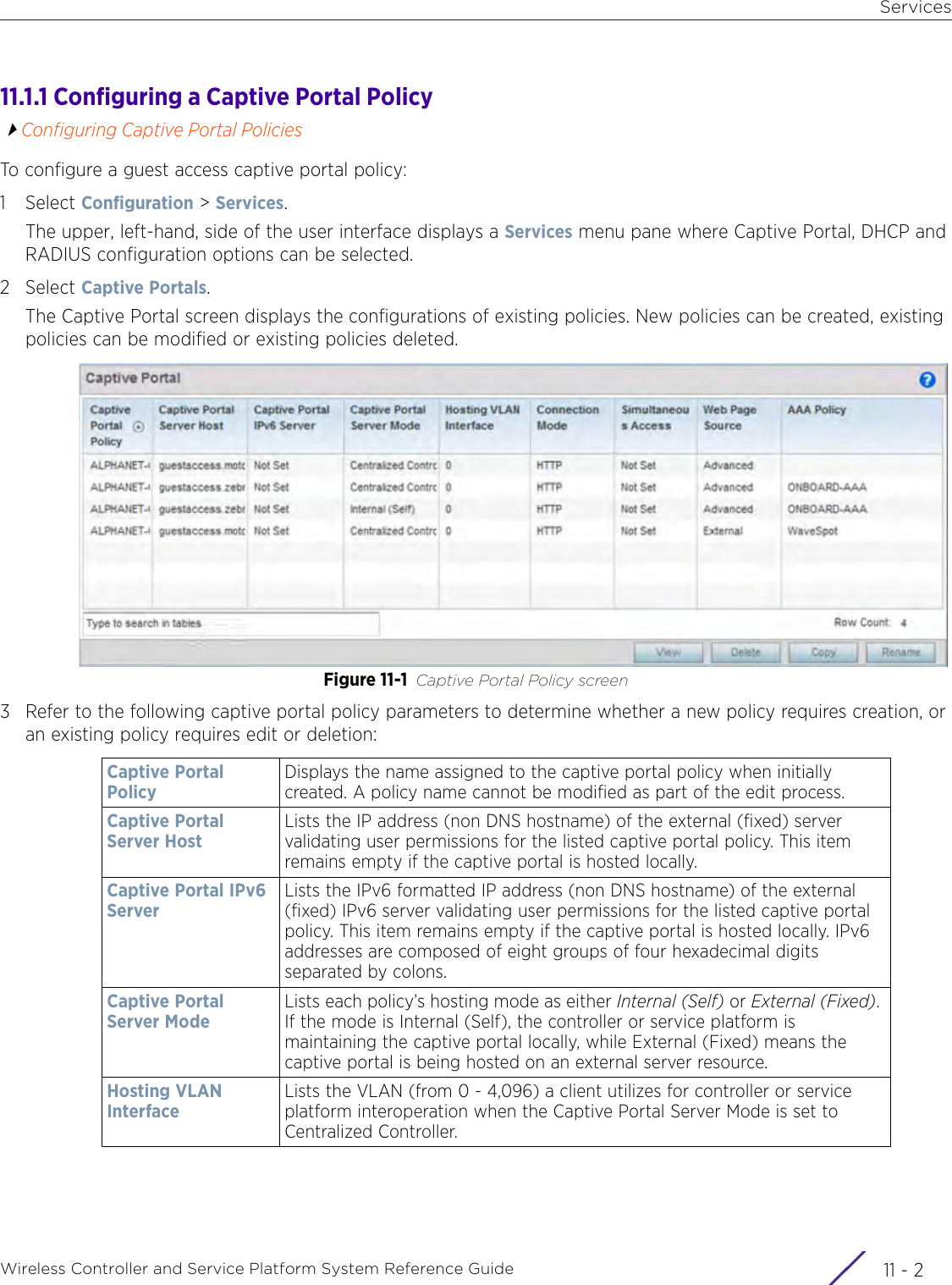
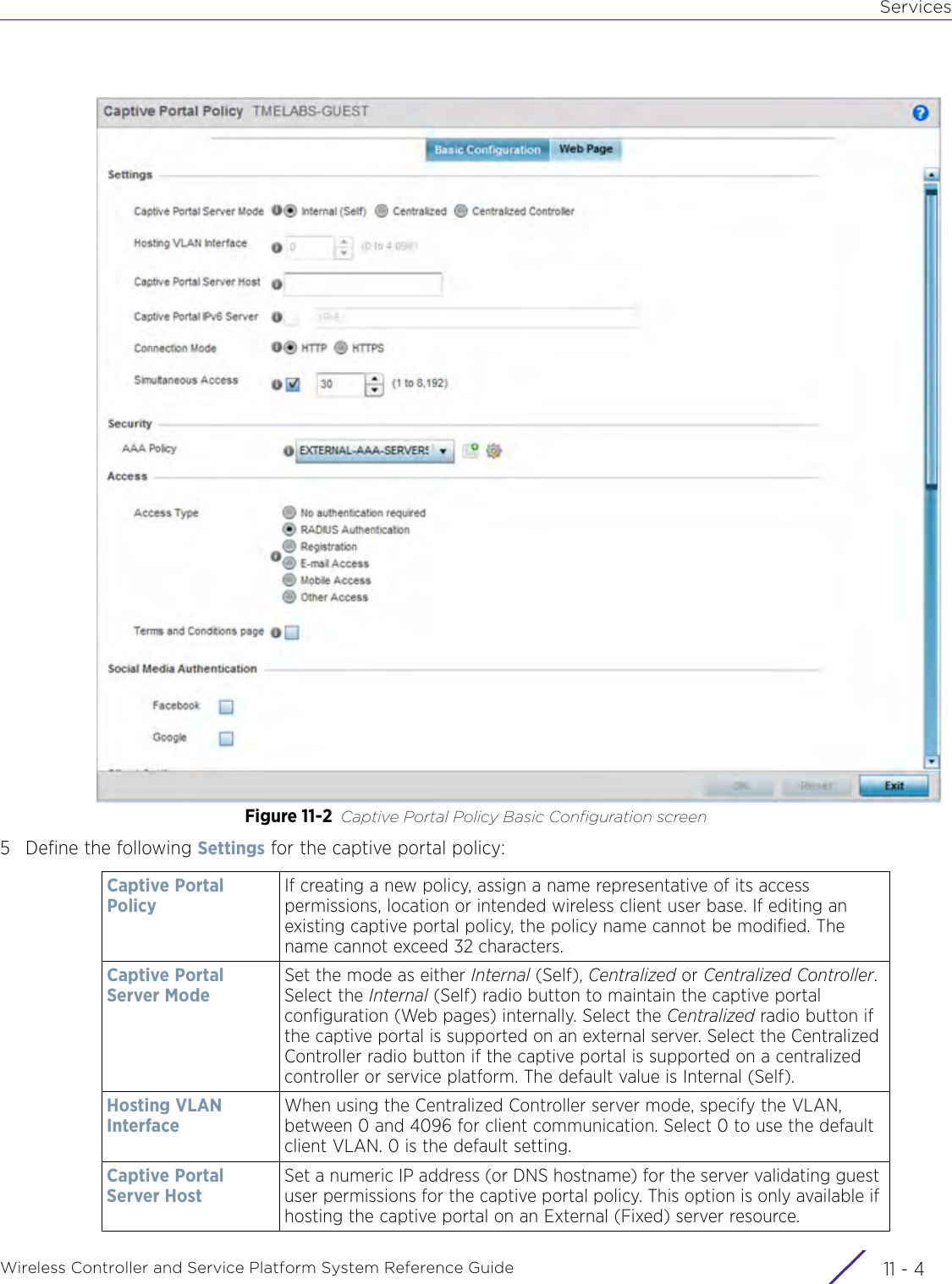
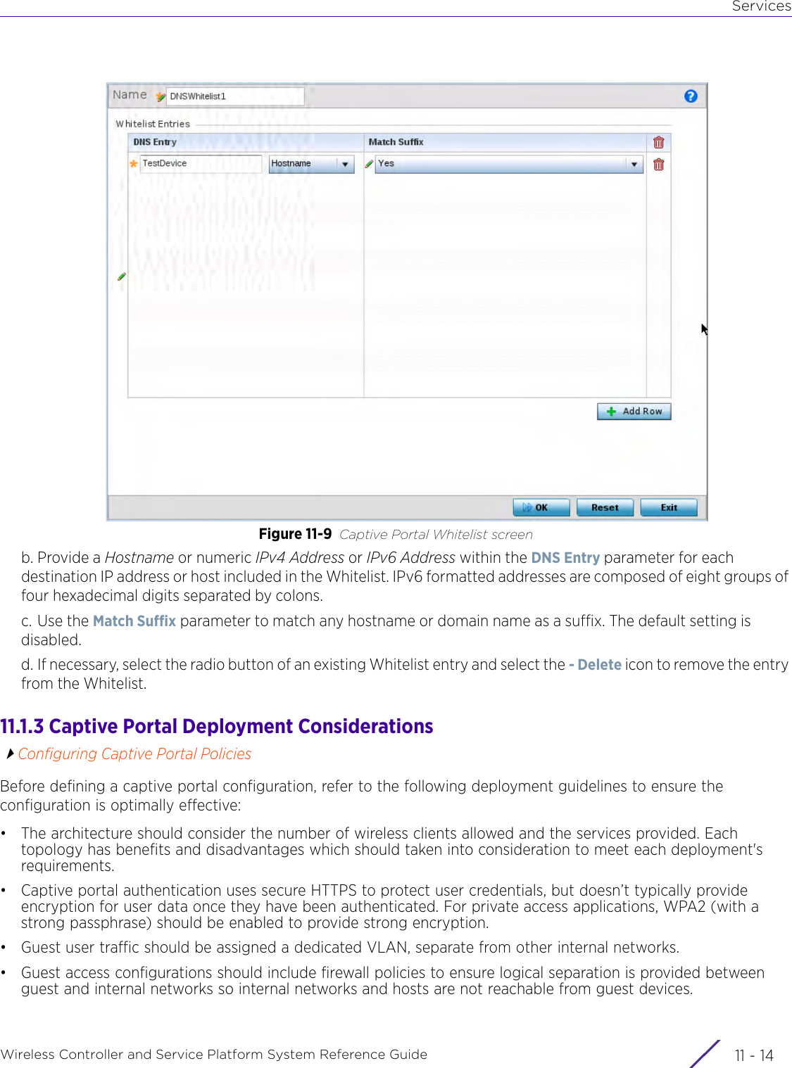
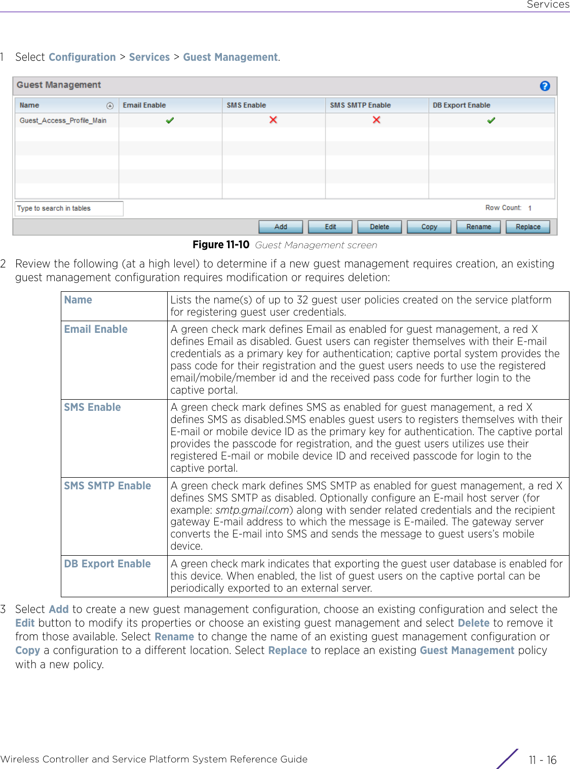
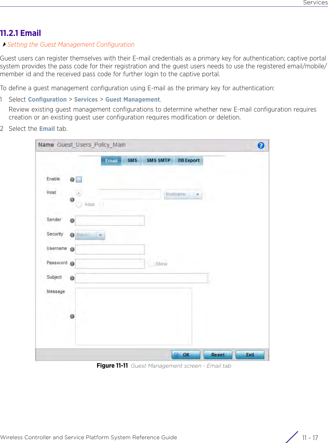
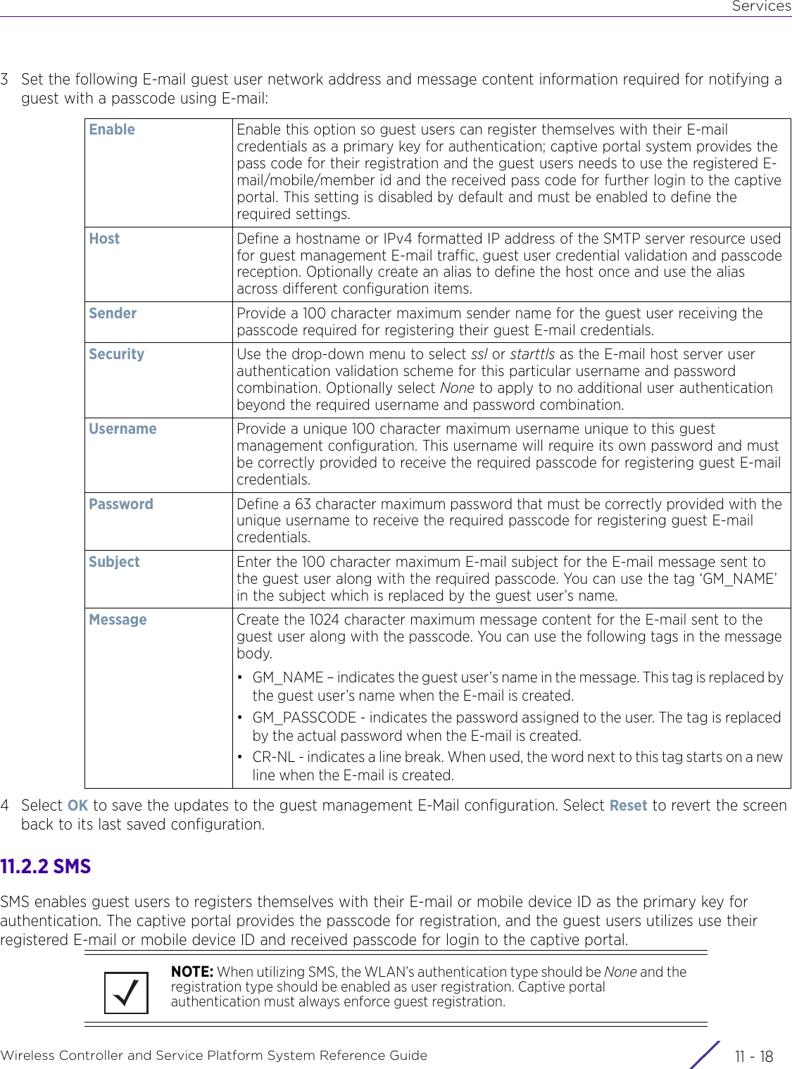
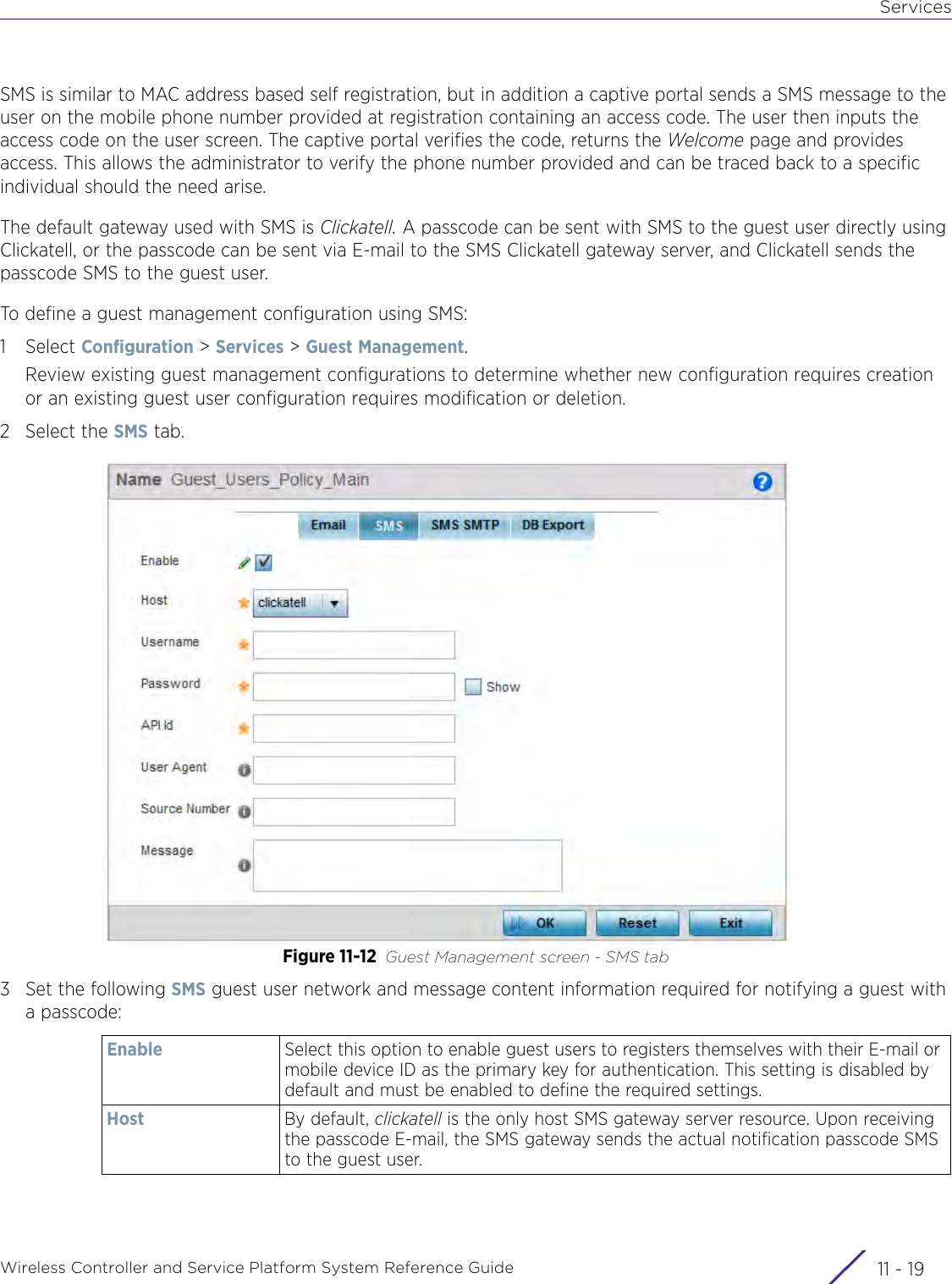
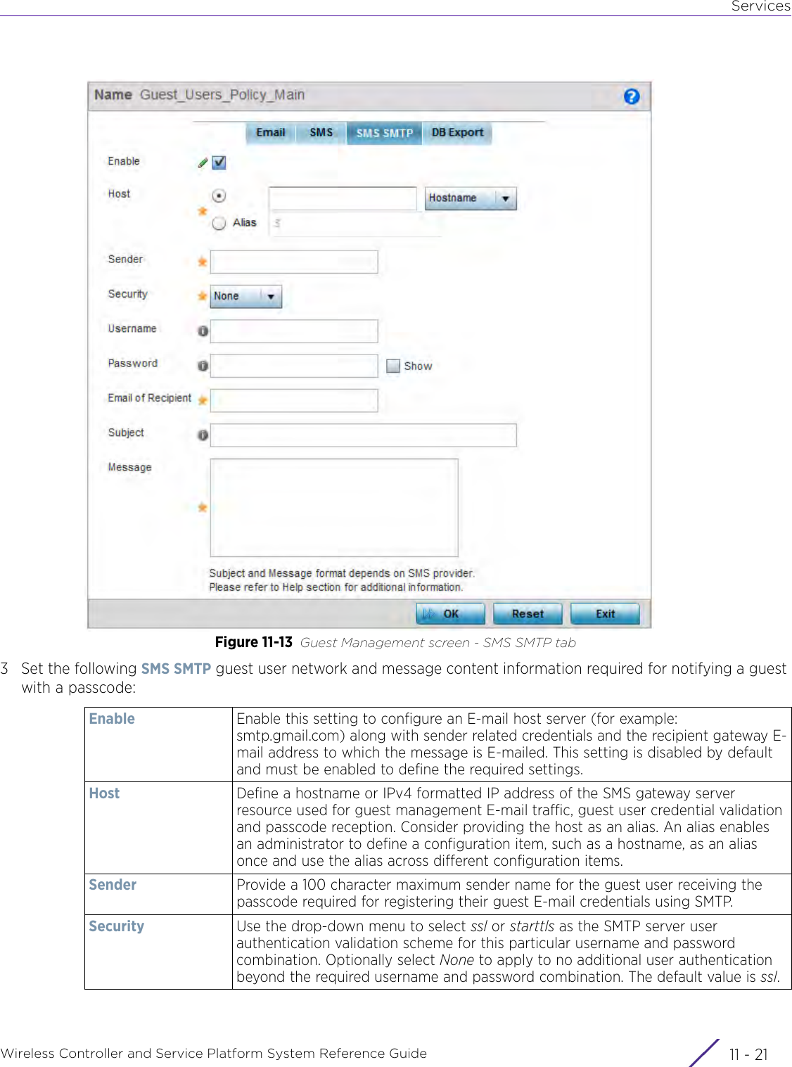
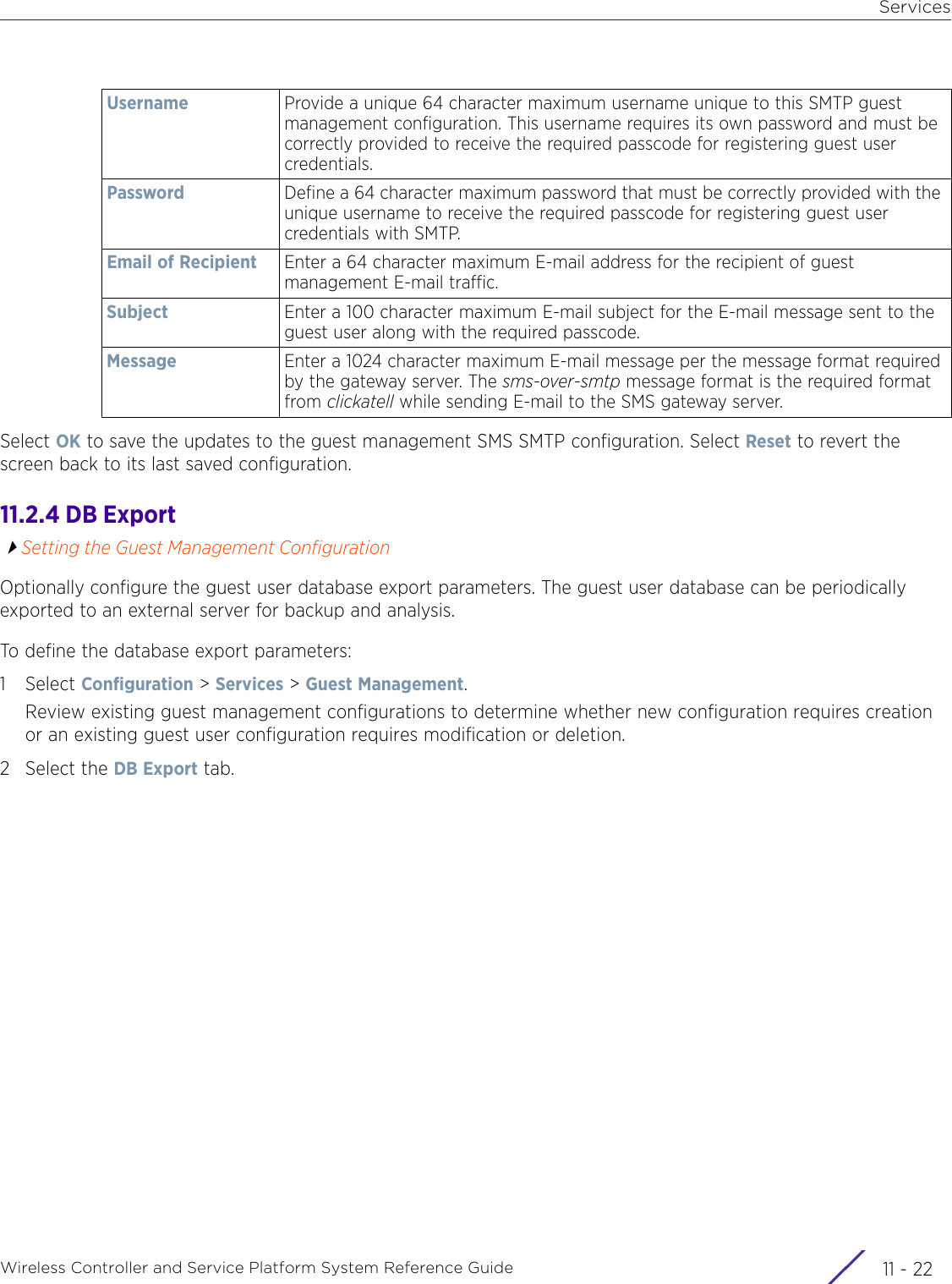
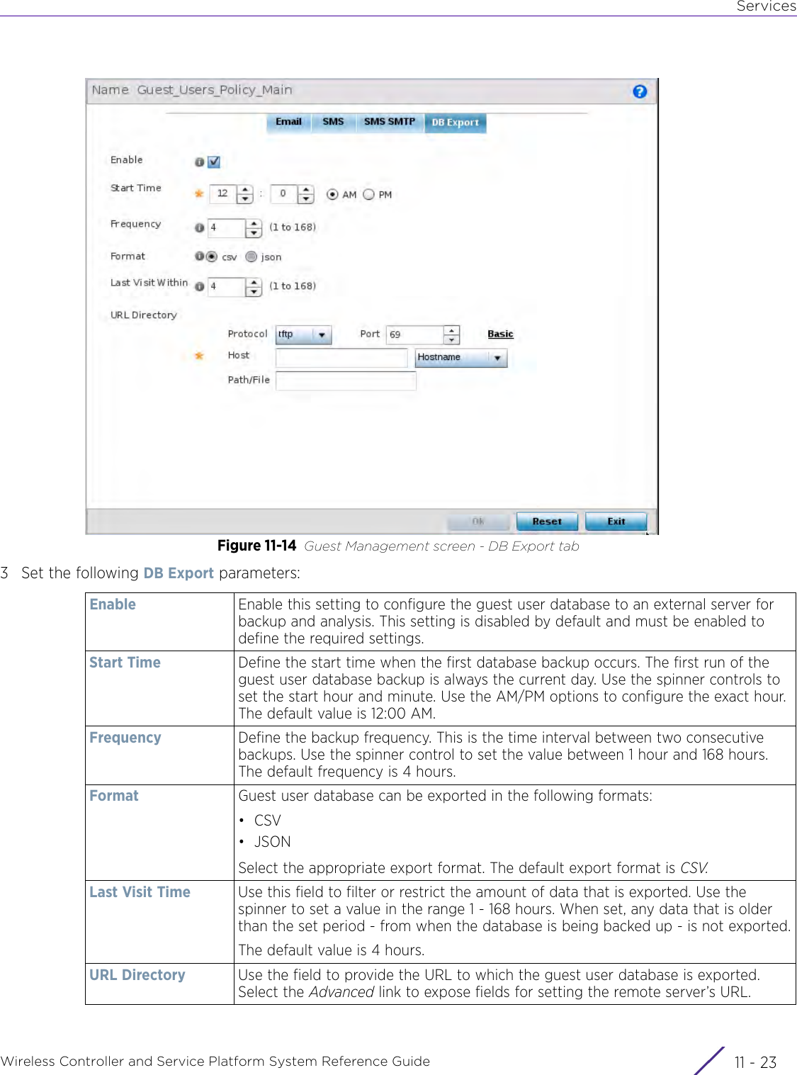
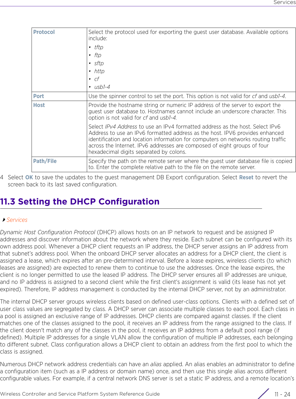
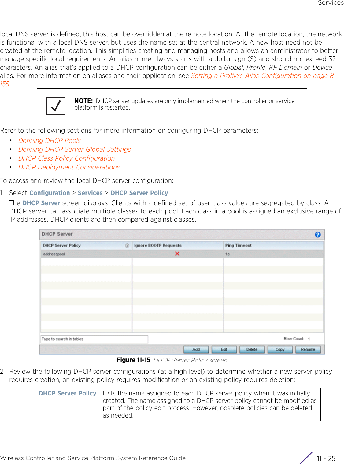
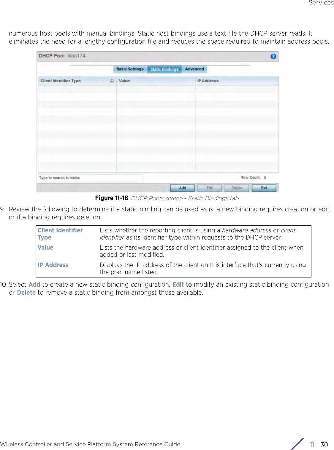
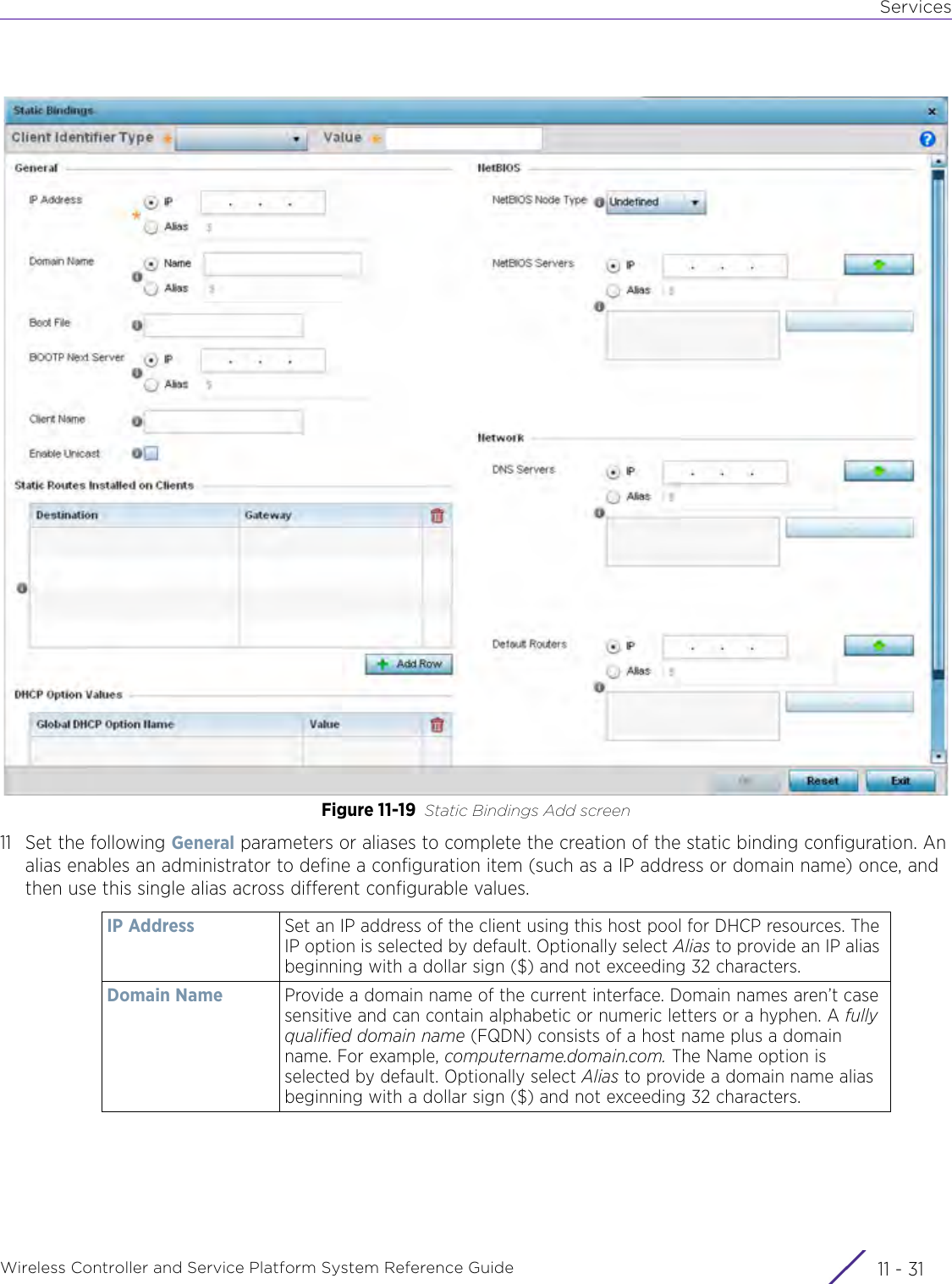
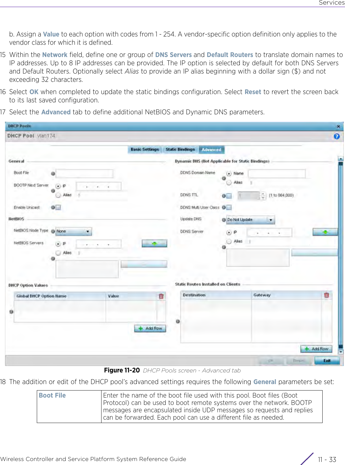
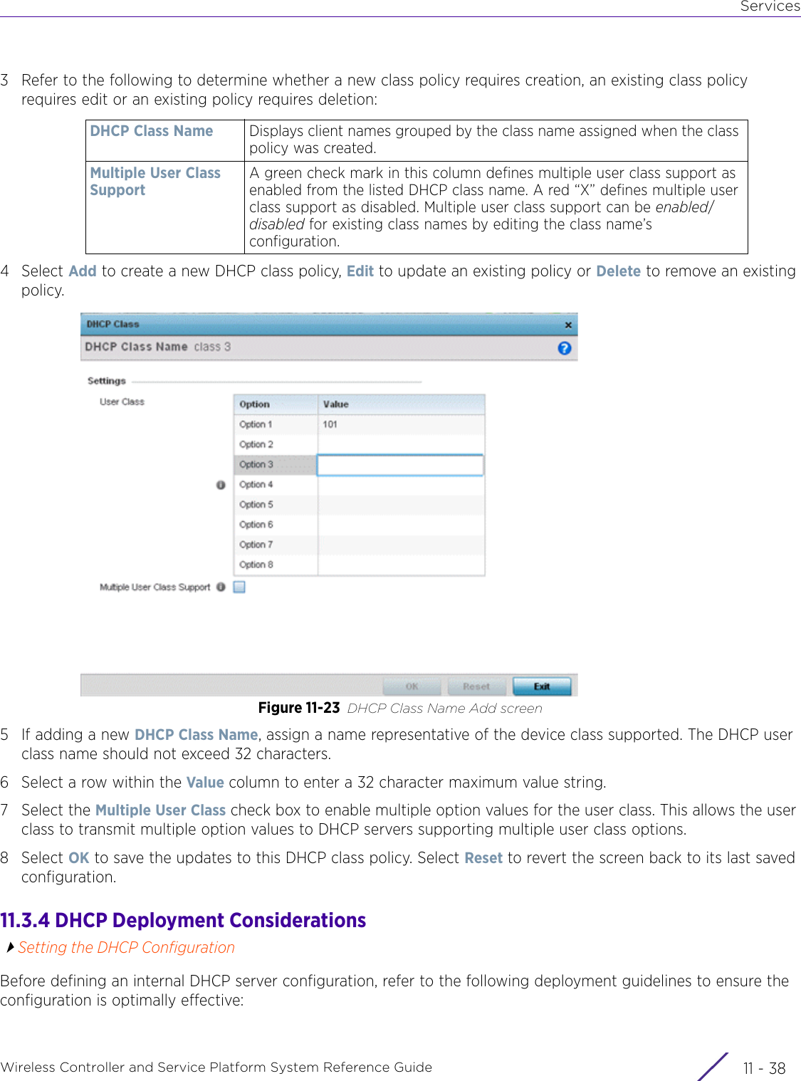
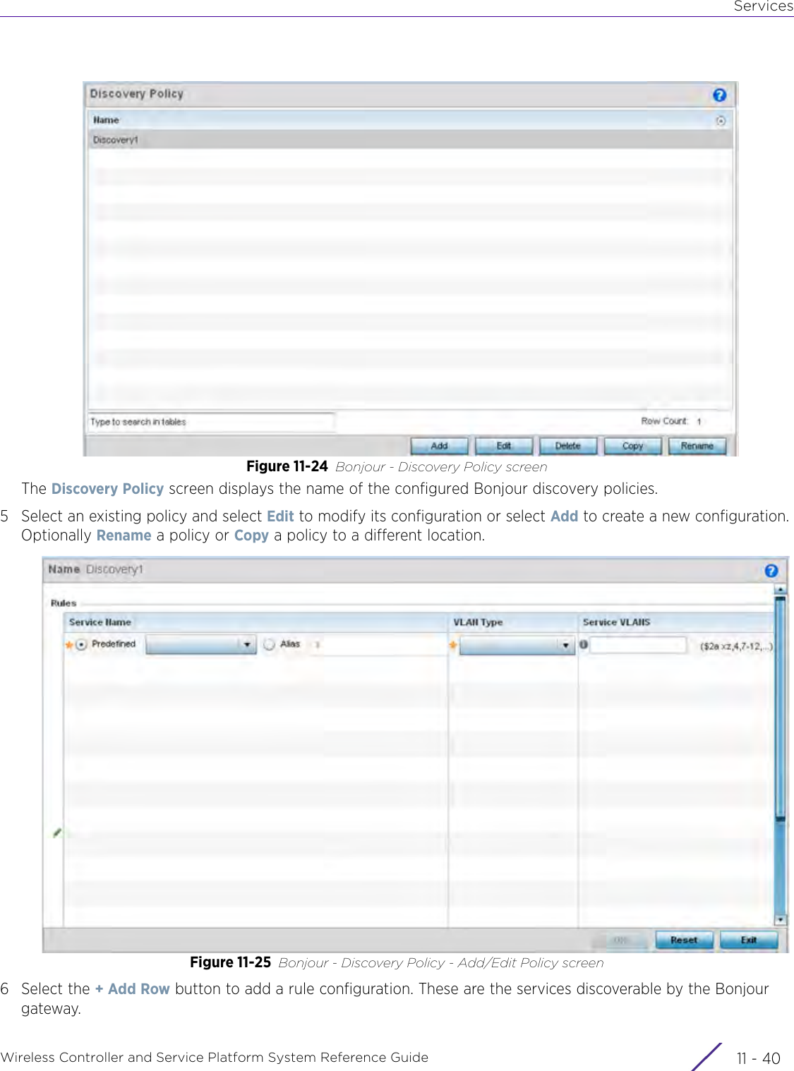
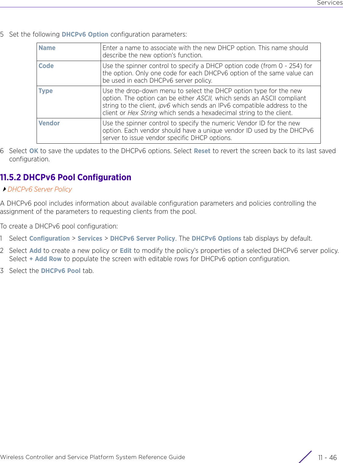
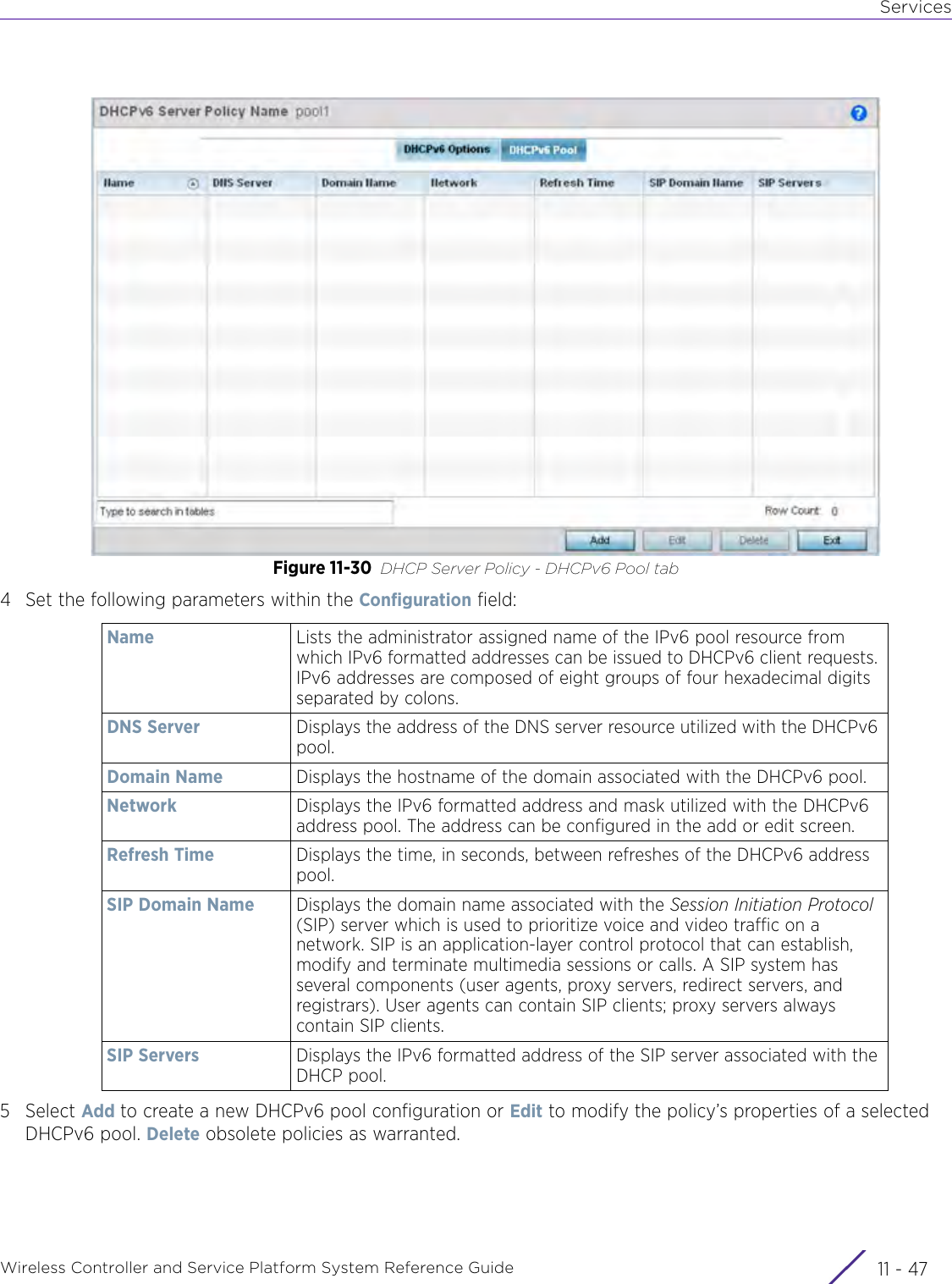
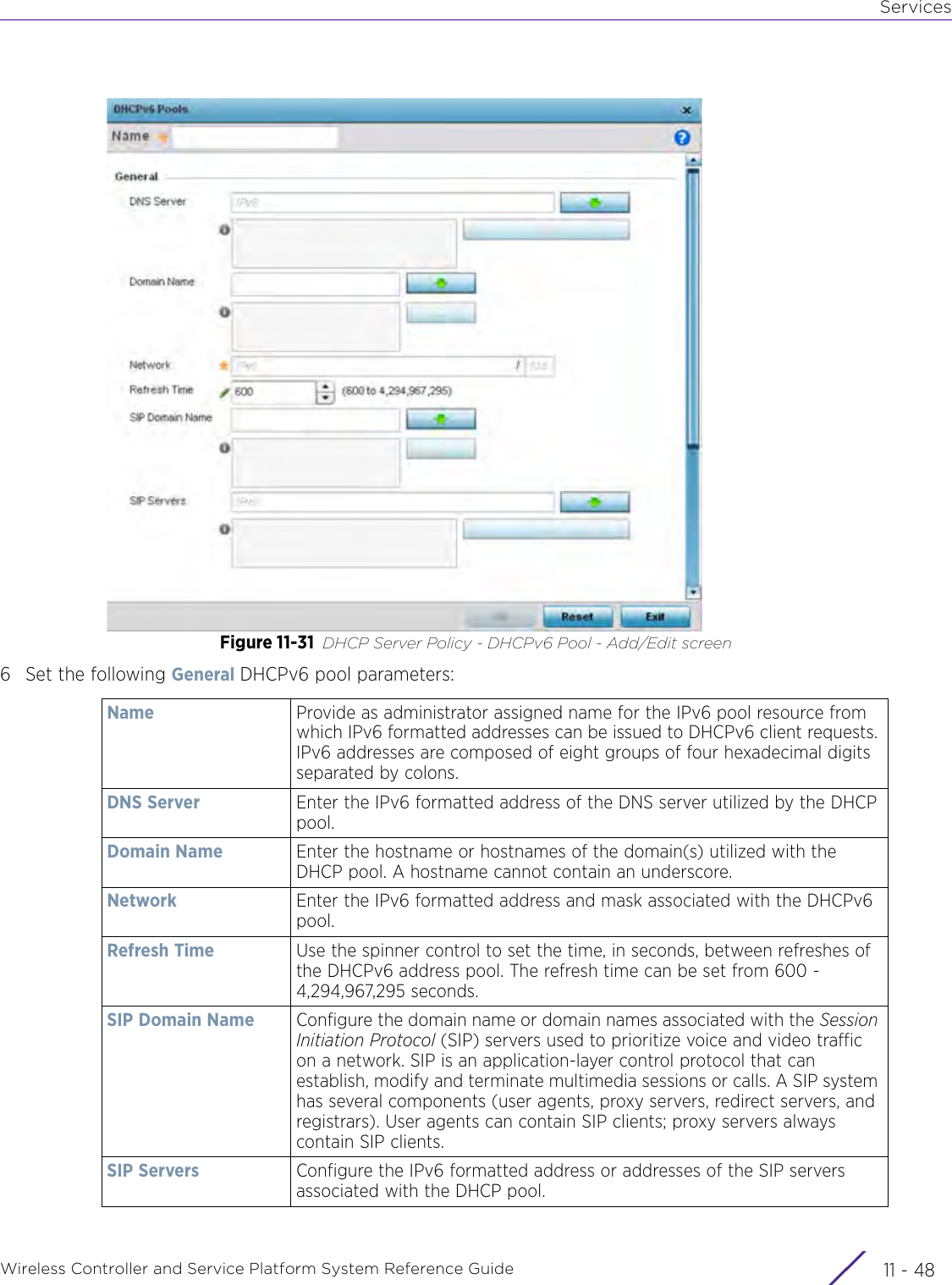
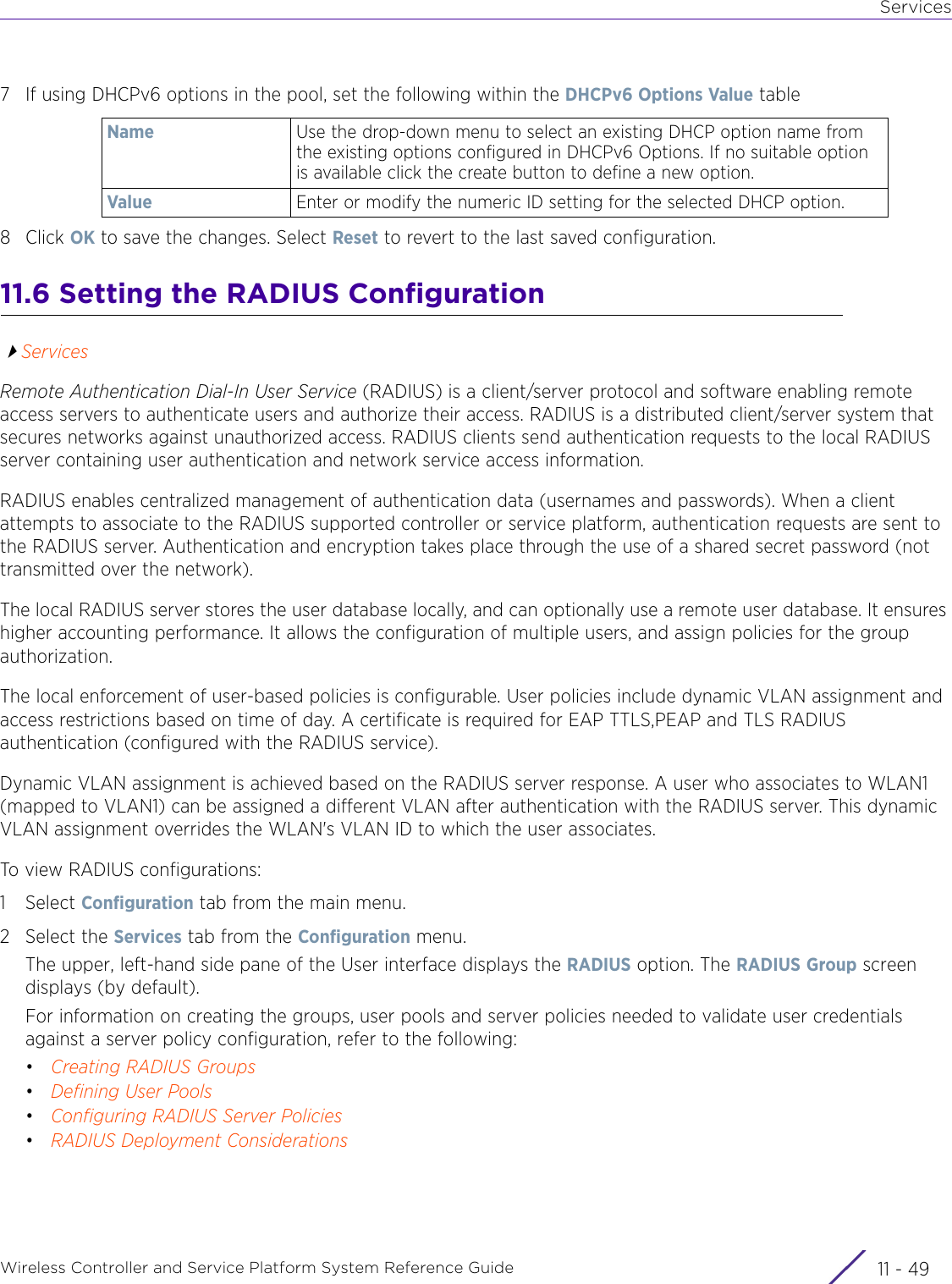
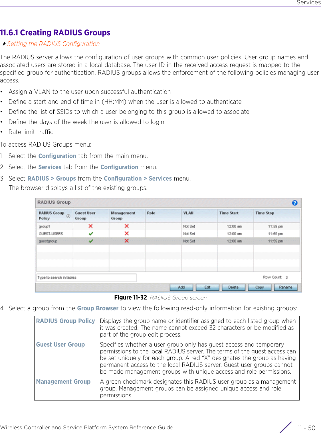
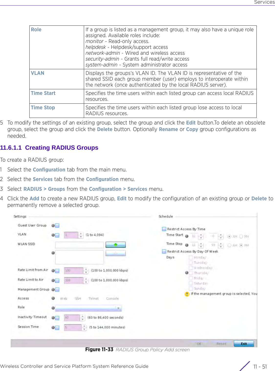
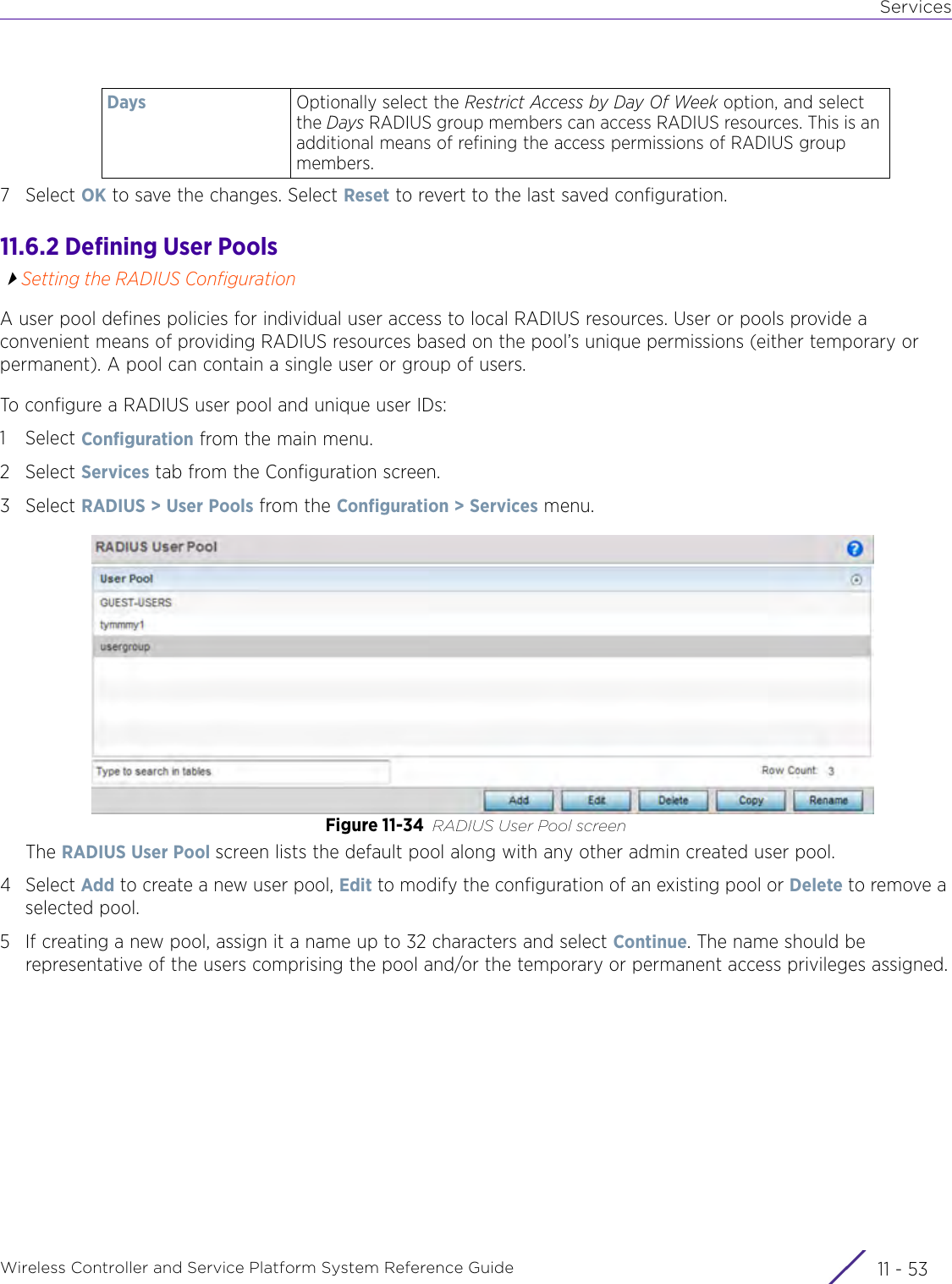
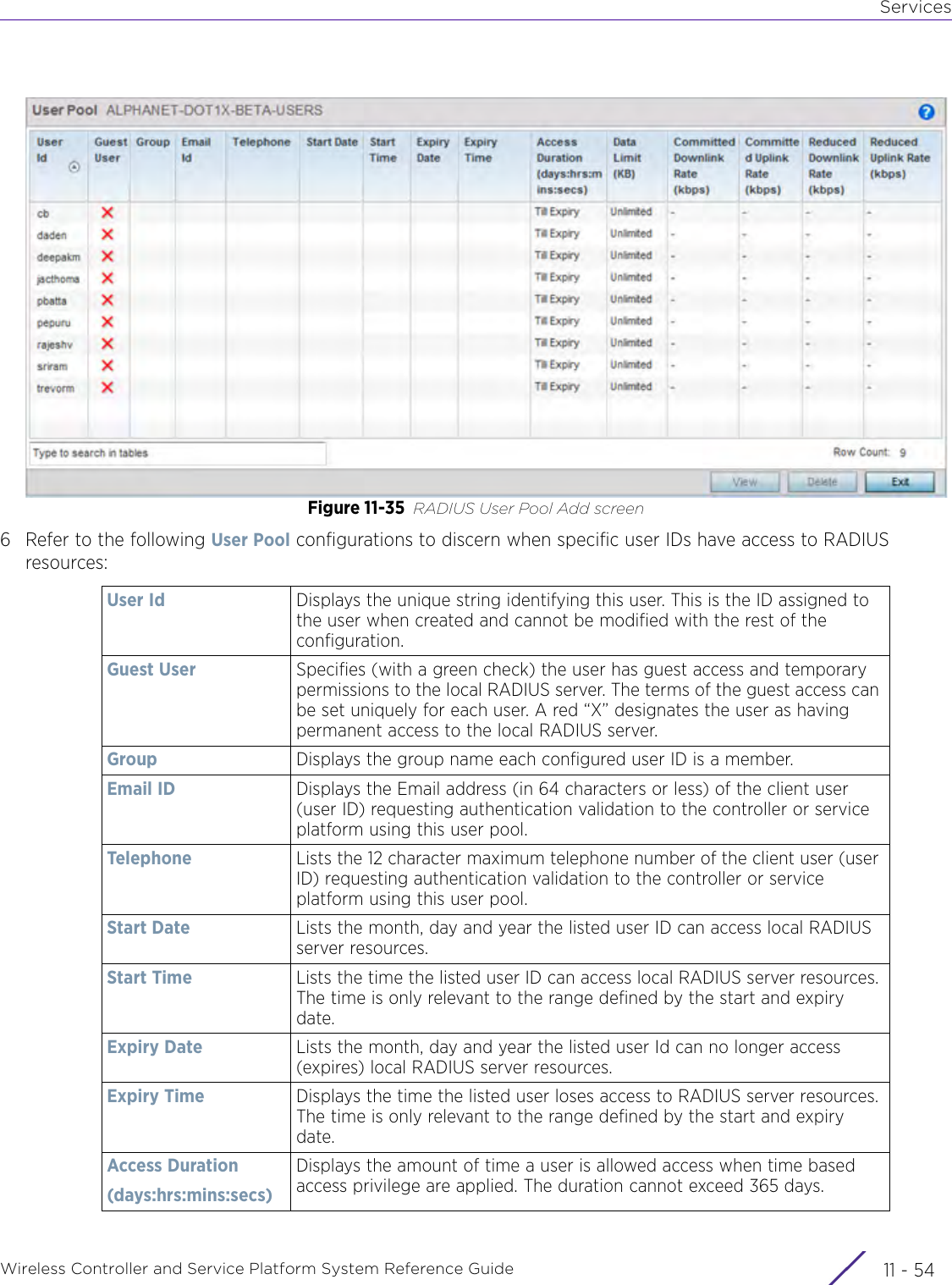
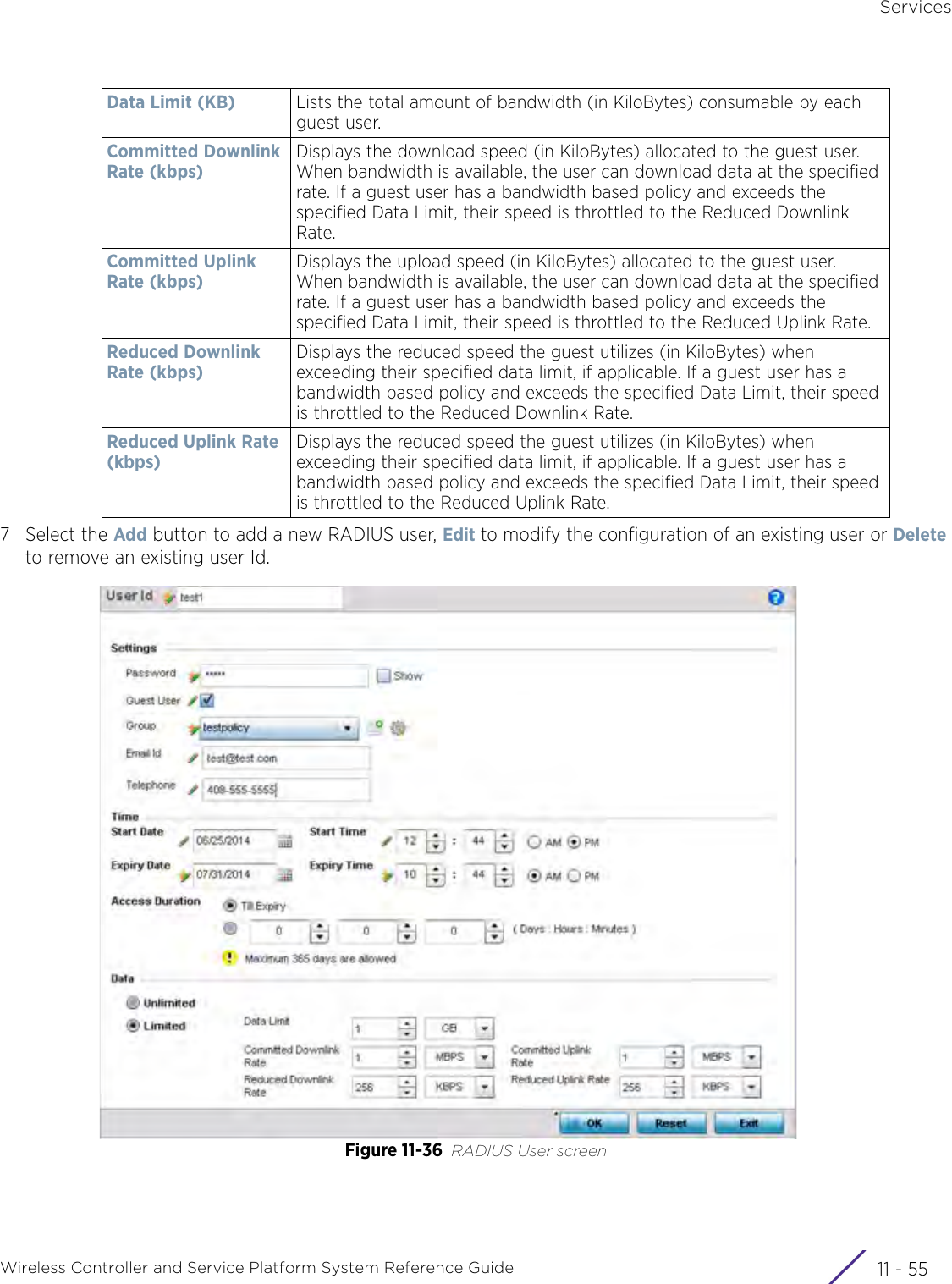
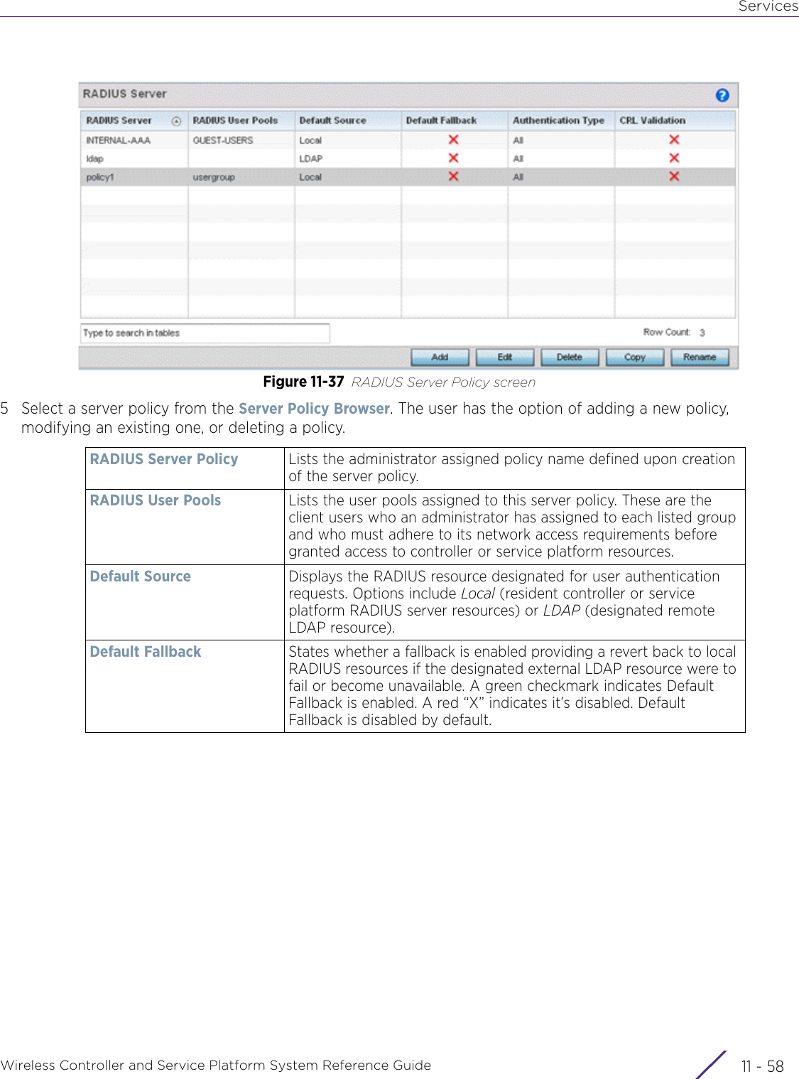
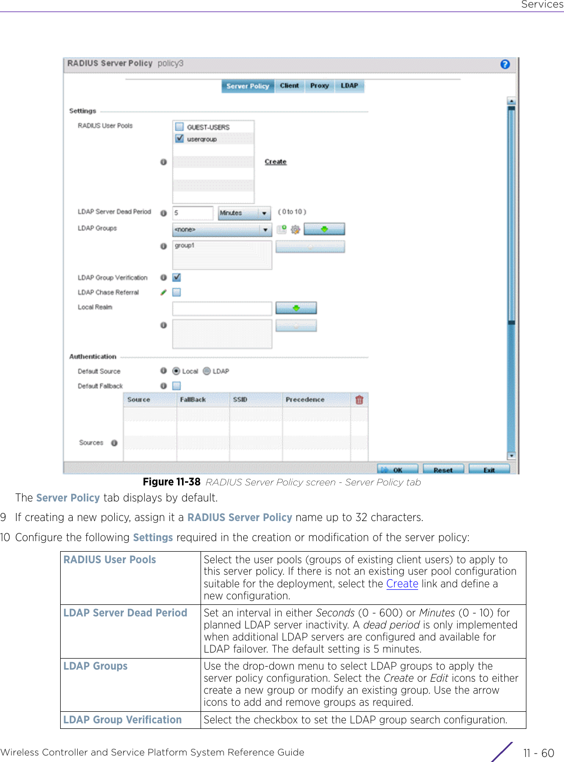
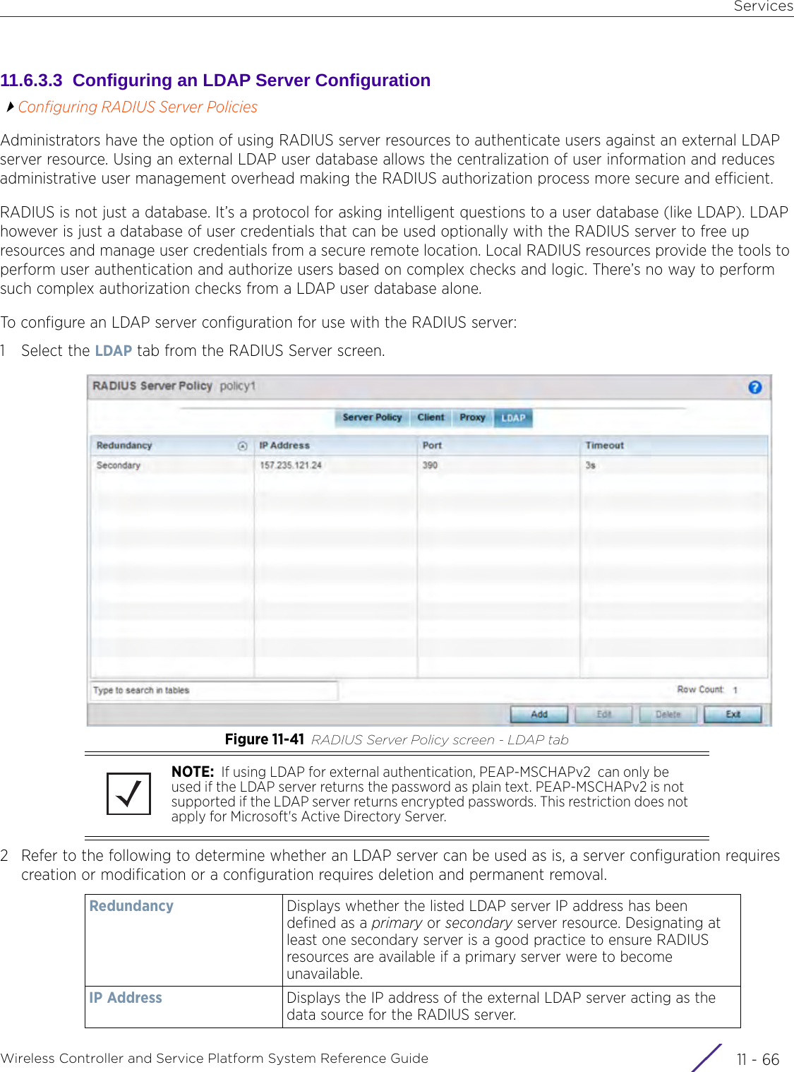
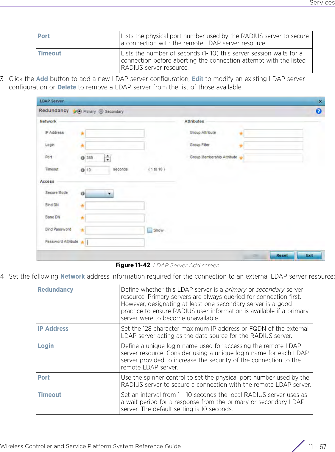
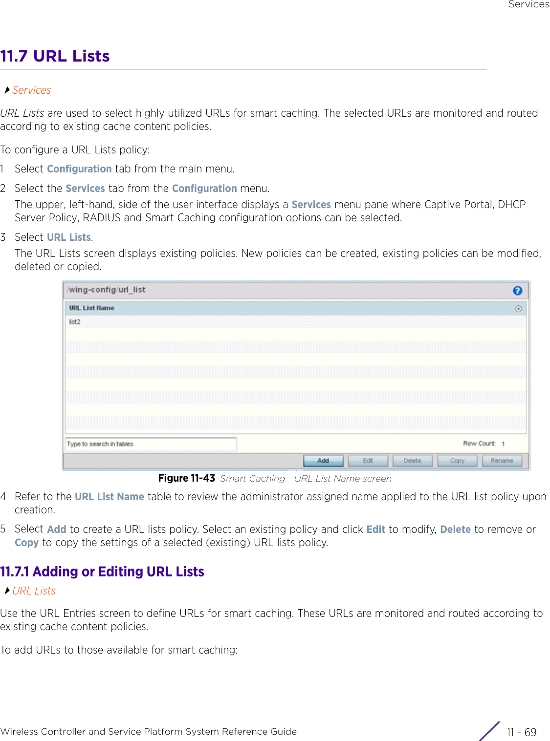
WiNG 5.9.1 System Reference Guide Part 2

Network ConfigurationWireless Controller and Service Platform System Reference Guide 7 - 33Select Policy Based Routing. The Policy Based Routing screen displays by default.Figure 7-1 Policy Based Routing screen 4 Either select Add to create a new PBR configuration, Edit to modify the attributes of an existing PBR configuration or Delete to remove a selected PBR configuration.5 If creating a new PBR policy assign it a Policy Name up to 32 characters to distinguish this route map configuration from others with similar attributes. Select Continue to proceed to the Policy Name screen where route map configurations can be added, modified or removed. Select Exit to exit without creating a PBR policy.Figure 7-2 Policy Based Routing, Policy Name screen 6 Refer to the following to determine whether a new route-map configuration requires creation or an existing route-map requires modification or removal:Precedence Lists the numeric precedence (priority) assigned to each listed PBR configuration. A routemap consists of multiple entries, each carrying a precedence value. An incoming packet is matched against the route-map with the highest precedence (lowest numerical value).DSCP Displays each policy’s DSCP value used as matching criteria for the route map. DSCP is the Differentiated Services Code Point field in an IP header and is for packet classification. Packets are filtered based on the traffic class defined in the IP DSCP field. One DSCP value can be configured per route map entry.
Network ConfigurationWireless Controller and Service Platform System Reference Guide  7 - 47Select Add or Edit to create or modify a route-map configuration. Configurations can optionally be removed by selecting Delete.Figure 7-3 Policy Based Routing screen - Add a Route Map8 If adding a route map, use the spinner control to set a numeric Precedence (priority) for this route-map. An incoming packet is matched against the route-map with the highest precedence (lowest numerical value).9 Refer to the Match Clauses field to define the following matching criteria for the route-map configuration:Role Policy Lists each policy’s role policy used as matching criteria.User Role Lists the user role defined in the Role Policy.Access Control List Displays each policy’s IP ACL used as an access/deny filter criteria for the route map.WLAN Displays each policy’s WLAN used as an access/deny filter for the route map.Incoming Interface Display the name of the Access Point WWAN or VLAN interface on which the packet is received for the listed PBR policy.DSCP Select this option to enable a spinner control to define the DSCP value used as matching criteria for the route map.DSCP is the Differentiated Services Code Point field in an IP header and is for packet classification. Packets are filtered based on the traffic class defined in the IP DSCP field. One DSCP value can be configured per route map entry.
Network ConfigurationWireless Controller and Service Platform System Reference Guide 7 - 510 Set the following Action Clauses to determine the routing function performed when a packet satisfies match criteria. Optionally fallback to destination based routing if no hop resource is available.11 Select OK to save the updates to the route-map configuration. Select Reset to revert to the last saved configuration.Role Policy Use the drop-down to select a Role Policy to use with this route-map.Click the Create icon to create a new Role Policy. To view and modify an existing policy, click the Edit icon.User Role Use the drop-down menu to select a role defined in the selected Role Policy. This user role is used while deciding the routing.Access Control List Use the drop-down menu to select an IP based ACL used as matching criteria for this route-map.Click the Create icon to create a new ACL. To view and modify an existing ACL, click the Edit icon.WLAN Use the drop-down menu to select the Access Point WLAN used as matching criteria for this route-map.Click the Create icon to create a new WLAN. To view and modify an existing WLAN, click the Edit icon.Incoming Interface Select this option to enable radio buttons used to define the interfaces required to receive route-map packets. Use the drop-down menu to define either the Access Point’s wwan1 or pppoe1 interface. Neither is selected by default. Or, select the VLAN ID option to define the Access Point VLAN to receive route-map-packets.Next Hop (Primary) Define a first hop priority request. Set either the IP address of the virtual resource or select the Interface option and define either a wwan1, pppoe1 or a VLAN interface. In the simplest terms, if this primary hop resource is available, its used with no additional considerations.Next Hop (Secondary)If the primary hop request were unavailable, a second resource can be defined. Set either the IP address of the virtual resource or select the Interface option and define either a wwan1, pppoe1 or a VLAN interface.Default Next Hop If a packet subjected to PBR does not have an explicit route to the destination, the configured default next hop is used. This value is set as either the IP address of the next hop or the outgoing interface. Only one default next hop can be defined. The difference between the next hop and the default next-hop is in case of former, PBR occurs first, then destination based routing. In case of the latter, the order is reverse. Set either the next hop IP address or define either a wwan1, pppoe1 or a VLAN interface.Use Destination RoutingIt may be a good idea to select this option to default back to destination based routing if none of the defined hop resources are reachable. Packets are dropped if a next hop resource is unavailable and fallback to destination routing is disabled. This option is enabled by default.Mark Select this option and use the spinner control to set IP DSCP bits for QoS using an ACL. The mark action of the route maps takes precedence over the mark action of an ACL.
Network ConfigurationWireless Controller and Service Platform System Reference Guide  7 - 67.2 L2TP V3 ConfigurationL2TP V3 is an IETF standard used for transporting different types of layer 2 frames in an IP network. L2TP V3 defines control and encapsulation protocols for tunneling layer 2 frames between two IP nodes.Use L2TP V3 to create tunnels for transporting layer 2 frames. L2TP V3 enables WiNG managed wireless devices to create tunnels for transporting Ethernet frames to and from bridge VLANs and physical ports. L2TP V3 tunnels can be defined between WiNG devices and other vendor devices supporting the L2TP V3 protocol. Multiple pseudowires can be created within an L2TP V3 tunnel. WiNG Access Points support an Ethernet VLAN pseudowire type exclusively. Ethernet VLAN pseudowires transport Ethernet frames to and from a specified VLAN. One or more L2TP V3 tunnels can be defined between tunnel end points. Each tunnel can have one or more L2TP V3 sessions. Each tunnel session corresponds to one pseudowire. An L2TP V3 control connection (a L2TP V3 tunnel) needs to be established between the tunneling entities before creating a session.For optimal pseudowire operation, both the L2TP V3 session originator and responder need to know the psuedowire type and identifier. These two parameters are communicated during L2TP V3 session establishment. An L2TP V3 session created within an L2TP V3 connection also specifies multiplexing parameters for identifying a pseudowire type and ID.The working status of a pseudowire is reflected by the state of the L2TP V3 session. If a L2TP V3 session is down, the pseudowire associated with it must be shut down. The L2TP V3 control connection keep-alive mechanism can serve as a monitoring mechanism for the pseudowires associated with a control connection. To define an L2TP V3 tunnel configuration: NOTE: A pseudowire is an emulation of a layer 2 point-to-point connection over a packet-switching network (PSN). A pseudowire was developed out of the necessity to encapsulate and tunnel layer 2 protocols across a layer 3 network.NOTE:  If connecting an Ethernet port to another Ethernet port, the pseudowire type must be Ethernet port, if connecting an Ethernet VLAN to another Ethernet VLAN, the pseudowire type must be Ethernet VLAN.
Network ConfigurationWireless Controller and Service Platform System Reference Guide 7 - 71Select Configuration > Network > L2TPv3.Figure 7-4 L2TP v3 Policy screen The L2TP V3 screen lists the policy configurations defined thus far.2 Refer to the following to determine whether a new L2TP V3 requires creation or modification:3Select Add to create a new L2TP V3 policy, Edit to modify the attributes of a selected policy or Delete to remove obsolete policies from the list of those available. Existing policies can be copied or deleted as needed.Name Lists the 31 character maximum name assigned to each listed L2TP V3 policy, designated upon creation.Cookie size Displays the size of each policy’s cookie field present within each L2TP V3 data packet. L2TP V3 data packets contain a session cookie which identifies the session (pseudowire) corresponding to it. If using the CLI, cookie size can't be configured per session, and are the same size for all sessions within a tunnel.Hello Interval Displays each policy’s interval between L2TP V3 hello keep alive messages exchanged within the L2TP V3 connection.Reconnect Attempt Lists each policy’s maximum number of reconnection attempts available to reestablish the tunnel if the connection is lost. Reconnect Interval Displays the duration set for each listed policy between two successive reconnection attempts. Retry Count Lists the number of retransmission attempts set for each listed policy before a target tunnel peer is defined as not reachable. Retry Time Out Lists the interval the interval (in seconds) set for each listed policy before the retransmission of a L2TP V3 signaling message. Rx Window Size Displays the number of packets that can be received without sending an acknowledgement. Tx Window Size Displays the number of packets that can be transmitted without receiving an acknowledgement. Failover Delay Lists the time (in either seconds or minutes) for establishing a tunnel after a failover (VRRP/RF Domain/Cluster).Force L2 Path RecoveryLists whether force L2 path recovery is enabled (as defined by a green checkmark) or disabled (as defined by a red X). Once a tunnel is established, enabling this setting forces server and gateway learning behind the L2TPv3 tunnel.
Network ConfigurationWireless Controller and Service Platform System Reference Guide  7 - 8Figure 7-5 L2TP V3 Policy Creation screen4 If creating a new L2TP V3 policy assign it a Name up to 31 characters. Remember, a single L2TP V3 policy can be used by numerous L2TP V3 tunnels.5 Define the following Policy Details to add a device to a list of devices sanctioned for network operation:Cookie size L2TP V3 data packets contain a session cookie which identifies the session (pseudowire) corresponding to it. Use the spinner control to set the size of the cookie field present within each L2TP V3 data packet. Options include 0, 4 and 8. the default setting is 0. If using the CLI, the cookie size can't be configured per session, and are the same size for all sessions within a tunnel.Hello Interval Define an interval in either Seconds (1 - 3,600), Minutes (1 -60) or Hours (1) between L2TP V3 hello keep alive messages exchanged within the L2TP V3 control connection. The default setting is 1 minute.Reconnect Attempt Use the spinner control to set a value (from 0 - 8) representing the maximum number of reconnection attempts initiated to reestablish the tunnel. The default interval is 0. Reconnect Interval Define an interval in either Seconds (1 - 3,600), Minutes (1 -60) or Hours (1) between two successive reconnection attempts. The default setting is 2 minutes.Retry Count Use the spinner control to define how many retransmission attempts are made before determining a target tunnel peer is not reachable. The available range is from 1 - 10, with a default value of 5.Retry Time Out Use the spinner control to define the interval (in seconds) before initiating a retransmission of a L2TP V3 signaling message. The available range is from 1 - 250, with a default value of 5.
Network ConfigurationWireless Controller and Service Platform System Reference Guide 7 - 96Select OK to save the updates to the L2TP V3 policy. Select Reset to revert to the last saved configuration.7.3 Crypto CMP PolicyCertificate Management Protocol  (CMP) is an Internet protocol to obtain and manage digital certificates in a Public Key Infrastructure (PKI) network. A Certificate Authority (CA) issues the certificates using the defined CMP.Using CMP, a device can communicate to a CMP supported CA server, initiate a certificate request and download the required certificates from the CA server. CMP supports multiple request options through for device communicating to a CMP supported CA server. The device can initiate a request for getting the certificates from the server. It can also auto update the certificates which are about to expire.The CMP client on the controller, service platform or Access Point triggers a request for the configured CMS CA server. Once the certificate is validated and confirmed from the CA server it is saved on the device and becomes part of the trustpoint. During the creation of the CMP policy the trustpoint is assigned a name and client information. An administrator can use a manually created trustpoint for one service (like HTTPs) and use the CMP generated trustpoint for RADIUS EAP certificate based authentication. To review, create or edit a Crypto CMP policy:Rx Window Size Specify the number of packets that can be received without sending an acknowledgement. The available range is from 1 - 15, with a default setting of 10.Tx Window Size Specify the number of packets that can be transmitted without receiving an acknowledgement. The available range is from 1 - 15, with a default setting of 10.Failover Delay Set the time in Seconds (5 - 60) or Minutes (1) for establishing a tunnel after a failover (VRRP/RF Domain/Cluster). The default setting is 5 seconds.Force L2 Path RecoveryDetermine whether force L2 path recovery is enabled or disabled. Once a tunnel is established, enabling this setting forces server and gateway learning behind the L2TPv3 tunnel. The default setting is disabled.
Network ConfigurationWireless Controller and Service Platform System Reference Guide  7 - 101Select Configuration > Network > Crypto CMP Policy.Figure 7-6 Crypto CMP Policy screen The Crypto CMP Policy screen lists the policy configurations defined thus far. 2Select Add to create a new Crypto CMP policy, Edit to modify the attributes of a selected policy or Delete to remove obsolete policies from the list of those available. Existing policies can be copied or renamed as needed.
Network ConfigurationWireless Controller and Service Platform System Reference Guide 7 - 11Figure 7-7 Crypto CMP Policy Creation screen3 If creating a new Crypto CMP policy assign it a Name up to 31 characters to help distinguish it.4 Set the Certificate Renewal Timeout period to trigger a new certificate renewal request with the dedicated CMP server resource. The range is 1-60 days. The default is 14 days.The expiration of the certificate is checked once a day. When a certificate is about to expire a certificate renewal is initiated with the server via an existing IPsec tunnel. If the tunnel is not established, the CMP renewal request is not sent. If a renewal succeeds the newly obtained certificate overwrites an existing certificate. If the renewal fails, an error is logged.5Select Certificate Update to update the renewal data of the certificate. This setting is enabled by default.6Select Certificate Validate to validate the cross-certificate when enabled. This setting is disabled by default.7Select Auto-gen Unique ID to add (prepend) an autogenerated ID in both the subject and sender fields. This setting is disabled by default.8Use the Certificate Key Size spinner control to set a key size (from 2,048 - 4096 bits) for the certificate request. The default key size is 2,048.
Network ConfigurationWireless Controller and Service Platform System Reference Guide  7 - 129Select + Add Row and define the following CMS Server Configuration settings for the server resource:10 Set the following Trust Points settings.The trustpoint is used for various services as specifically set the controller, service platform or Access Point.11 Use the SAN Type drop-down menu to provide an alternative name (disguise) for the subject. Options include email, IP Address, Distinguished Name, FQDN and string.12 Use the SAN Value field to enter a 128 character maximum alternative value for the subject.13 Select OK to save the updates to the CMP Crypto policy, Reset to revert to the last saved configuration, or Exit to close the screen.7.4 AAA PolicyAuthentication, Authorization, and Accounting (AAA) provides the mechanism by which network administrators define access control within the network. Controllers, service platforms and Access Points can interoperate with external RADIUS and LDAP Servers (AAA Servers) to provide user database information and user authentication data. Each WLAN can maintain its own unique AAA configuration.AAA provides a modular way of performing the following services: Enable Use the drop-down menu to set the CMS server as either the Primary (first choice) or Secondary (secondary option) CMP server resource.IP Define the IP address for the CMP CA server managing digital certificate requests. CMP certificates are encrypted with CA's public key and transmitted to the defined IP destination over a typical HTTP or TLS session.Path Provide a complete path to the CMP CA’s trustpoint.Port Provide a CMP CA port number.Name Enter the 32 character maximum name assigned to the target trustpoint. A trustpoint represents a CA/identity pair containing the identity of the CA, CA specific configuration parameters, and an association with an enrolled identity certificate. This field is mandatory.Subject Name Provide a subject name of up to 512 characters for the certificate template example. This field is mandatory.Reference ID Set the user reference value for the CMP CA trust point message. The range is 0-256. This field is mandatory.Secret Specify the secret used for trustpoint authentication over the designated CMP server resource.Sender Name Enter a sender name up to 512 characters for the trustpoint request. This field is mandatory.Recipient Name Enter a recipient name value of up to 512 characters for the trustpoint request.
Network ConfigurationWireless Controller and Service Platform System Reference Guide 7 - 13Authentication — Authentication provides a means for identifying users, including login and password dialog, challenge and response, messaging support and (depending on the security protocol), encryption. Authentication is the technique by which a user is identified before allowed access to the network. Configure AAA authentication by defining a list of authentication methods, and then applying the list to various interfaces. The list defines the authentication schemes performed and their sequence. The list must be applied to an interface before the defined authentication technique is conducted. Authorization — Authorization occurs immediately after authentication. Authorization is a method for remote access control, including authorization for services and individual user accounts and profiles. Authorization functions through the assembly of attribute sets describing what the user is authorized to perform. These attributes are compared to information contained in a database for a given user and the result is returned to AAA to determine the user's actual capabilities and restrictions. The database could be located locally or be hosted remotely on a RADIUS server. Remote RADIUS servers authorize users by associating attribute-value (AV) pairs with the appropriate user. Each authorization method must be defined through AAA. When AAA authorization is enabled it’s applied equally to all interfaces. Accounting — Accounting is the method for collecting and sending security server information for billing, auditing, and reporting user data; such as start and stop times, executed commands (such as PPP), number of packets, and number of bytes. Accounting enables wireless network administrators to track the services users are accessing and the network resources they are consuming. When accounting is enabled, the network access server reports user activity to a RADIUS security server in the form of accounting records. Each accounting record is comprised of AV pairs and is stored on the access control server. The data can be analyzed for network management, client billing, and/or auditing. Accounting methods must be defined through AAA. When AAA accounting is activated, it’s applied equally to all interfaces on the access servers.To define unique WLAN AAA configurations:1Select Configuration > Network > AAA Policy to display existing AAA policies.The Authentication, Authorization, and Accounting (AAA) screen lists those AAA policies created thus far. Any of these policies can be selected and applied. Figure 7-8 Authentication, Authorization, and Accounting (AAA) screen2 Refer to the following information listed for each existing AAA policy:AAA Policy Displays the name assigned to the AAA TACACS policy when it was initially created. The name cannot be edited within a listed profile.
Network ConfigurationWireless Controller and Service Platform System Reference Guide  7 - 143 To configure a new AAA policy, click the Add button. To modify an existing policy, select it from amongst those available and select the Edit button. Optionally Copy or Rename the AAA policy as needed.Figure 7-9 AAA Policy - RADIUS Authentication screen4 Refer to the following AAA authentication policy data:Accounting Packet Type Displays the accounting type set for the AAA policy. Options include:Start Only - Sends a start accounting notice to initiate user accounting. Start/Stop - Sends a start accounting notice at the beginning of a process and a stop notice at the end of a process. The start accounting record is sent in the background. The requested process begins regardless of whether the start accounting notice is received by the accounting server.Start/Interim/Stop - Sends a start accounting notice at the beginning of a process and a stop notice at the end of a process. A notice is also sent at the completion of each interim packet transmission during the process.Request Interval Lists each AAA policy’s interval used to send a RADIUS accounting request to the RADIUS server.NAC Policy Lists the name Network Access Control (NAC) filter used to either include or exclude clients from access.Server Pooling Mode The server pooling mode controls how requests are transmitted across RADIUS servers. Selecting Failover results in working down the list of servers if a server is unresponsive or unavailable. Load Balanced uses all available servers transmitting requests in round robin.Server ID Displays the numerical server index (1-6) for the accounting server when added to the list available.Server Type Displays the type of AAA server in use either Host, onboard-self, or onboard-controller.Host Displays the IP address or hostname of the RADIUS authentication server.
Network ConfigurationWireless Controller and Service Platform System Reference Guide 7 - 155 Select a configuration from the table and select Edit, or select Add to create a new RADIUS authentication policy. Optionally Delete a policy as they become obsolete.Port Displays the port on which the RADIUS server listens to traffic within the network. The port range is 1 to 65,535. The default port is 1812.Request Proxy Mode Displays whether a request is transmitted directly through the server or proxied through the Access Point or RF Domain manager.Request Attempts Displays the number of attempts a client can retransmit a missed frame to the RADIUS server before it times out of the authentication session. The available range is between 1 and 10 attempts. The default is 3 attempts.Request Timeout Displays the time (from 1 - 60) seconds for the re-transmission of request packets. The default is 3 seconds. If this time is exceeded, the authentication session is terminated.DSCP Displays the DSCP value as a 6-bit parameter in the header of every IP packet used for packet classification. The valid range is from 0 - 63 with a default of 46.NAI Routing Enable Displays NAI routing status. AAA servers identify clients using the NAI. The NAI is a character string in the format of an e-mail address as either user or user@ but it need not be a valid e-mail address or a fully qualified domain name. The NAI can be used either in a specific or generic form. The specific form, which must contain the user portion and may contain the @ portion, identifies a single user. The generic form allows all users to be configured on a single command line. Each user still needs a unique security association, but these associations can be stored on a AAA server. The original purpose of the NAI was to support roaming between dialup ISPs. Using NAI, each ISP need not have all the accounts for all of its roaming partners in a single RADIUS database. RADIUS servers can proxy requests to remote servers for each.NAC Enable A green check defines NAC as enabled, while a Red X defines NAC disabled with this AAA policy.
Network ConfigurationWireless Controller and Service Platform System Reference Guide  7 - 16Figure 7-10 AAA Policy - Add RADIUS Authentication Server6 Define the following Settings to add or modify a AAA RADIUS authentication server configuration:Server ID If adding a server, define the numerical server index (1-6) for the authentication server when added to the list available.Server Type Select the type of AAA server in use either Host, onboard-self, onboard-controller or onboard-centralized-controller.Host Specify the IP address or hostname of the RADIUS authentication server. Hostnames cannot include an underscore character.Port Define or edit the port on which the RADIUS server listens to traffic within the network. The port range is 1 to 65,535. The default port is 1812.Secret Specify the secret used for authentication on the selected RADIUS server. By default the secret will be displayed as asterisks. To show the secret in plain text, check the Show box. Request Proxy Mode Select the method of proxy that browsers communicate with the RADIUS authentication server. The mode could either be None, Through Wireless Controller, through-centralized-controller, Through RF Domain Manager, or Through Mint Host.Request Mint Host Specify a 64 character maximum hostname (or Mint ID) of the Mint device used for proxying requests. Hostnames cannot include an underscore character.Request Attempts Specify the number of attempts a client can retransmit a missed frame to the RADIUS server before it times out of the authentication session. The available range is between 1 and 10 attempts. The default is 3 attempts.
Network ConfigurationWireless Controller and Service Platform System Reference Guide 7 - 177 Set the following Network Access Identifier Routing values:8 Select the RADIUS Accounting tab.Request Timeout Specify the time between 1 and 60 seconds for the re-transmission of request packets. The default is 5 seconds. If this time is exceeded, the authentication session is terminated.Request Timeout Factor Specify the amount of time between 50 and 200 seconds between retry timeouts for the re-transmission of request packets. The default is 100.DSCP Specify the DSCP value as a 6-bit parameter in the header of every IP packet used for packet classification. The valid range is between 0 and 63 with a default value of 46.NAI Routing Enable Check to enable NAI routing. AAA servers identify clients using the NAI. The NAI is a character string in the format of an e-mail address as either user or user@ but it need not be a valid e-mail address or a fully qualified domain name. The NAI can be used either in a specific or generic form. The specific form, which must contain the user portion and may contain the @ portion, identifies a single user. The generic form allows users to be configured on a single command line. Each user still needs a unique security association, but these associations can be stored on a AAA server. The original purpose of the NAI was to support roaming between dialup ISPs. Using NAI, each ISP need not have all the accounts for all of its roaming partners in a single RADIUS database. RADIUS servers can proxy requests to remote servers for each.Realm Enter the realm name in the field. The name cannot exceed 50 characters. When the RADIUS server receives a request for a user name the server references a table of usernames. If the user name is known, the server proxies the request to the RADIUS server.Realm Type Specify whether the Prefix or Suffix of the username is matched to the realm.Strip Realm Check strip to remove information from the packet when NAI routing is enabled.
Network ConfigurationWireless Controller and Service Platform System Reference Guide  7 - 18Figure 7-11 AAA Policy - RADIUS Accounting screen9 Refer to the following information for each existing AAA server policy to determine whether new RADIUS accounting policies require creation or existing policies require modification:Server ID Displays the numerical server index (1-6) for the accounting server assigned when added to the WiNG operating system.Host Displays the IP address or hostname of the RADIUS authentication server. Hostnames cannot include an underscore character.Port Displays the port on which the RADIUS server listens to traffic within the network. The port range is 1 to 65,535. The default port is 1813.Server Type Displays the type of AAA server in use either Host, onboard-self, or onboard-controller.Request Timeout Displays the time between 1 and 60 seconds for the wireless controller’s re-transmission of request packets. If this time is exceeded, the authentication session is terminated.Request Attempts Displays the number of attempts a client can retransmit a missed frame to the RADIUS server before it times out of the authentication session. The available range is between 1 and 10 attempts. The default is 3 attempts.DSCP Displays the DSCP value as a 6-bit parameter in the header of every IP packet used for packet classification. The valid range is between 0 and 63 with a default value of 34.Request Proxy Mode Displays the method of proxy that browsers communicate with the RADIUS authentication server. The mode could either be None, Through Wireless Controller, or Through RF Domain Manager.
Network ConfigurationWireless Controller and Service Platform System Reference Guide 7 - 1910 To edit an existing accounting profile, select the profile then Edit. To add a new policy select Add. Optionally Delete a policy as they become obsolete.Figure 7-12 AAA Policy - Add RADIUS Accounting Server11 If creating a new AAA Accounting Server configuration as a user database and user authentication resource, assign it a Server ID from 1 - 6.12 Define the following Settings to add or modify AAA RADIUS accounting server configuration.NAI Routing Enable Displays NAI routing status. AAA servers identify clients using the NAI. The NAI is a character string in the format of an e-mail address as either user or user@ but it need not be a valid e-mail address or a fully qualified domain name. The NAI can be used either in a specific or generic form. The specific form, which must contain the user portion and may contain the @ portion, identifies a single user. The generic form allows all users to be configured on a single command line. Each user still needs a unique security association, but these associations can be stored on a AAA server. The original purpose of the NAI was to support roaming between dialup ISPs. Using NAI, each ISP need not have all the accounts for all of its roaming partners in a single RADIUS database. RADIUS servers can proxy requests to remote servers for each.Server Type Select the type of AAA server as either Host, onboard-self, onboard-controller or onboard-centralized-controller.
Network ConfigurationWireless Controller and Service Platform System Reference Guide  7 - 2013 Set the following Network Access Identifier routing values for the accounting server:Host Specify the IP address or hostname of the RADIUS accounting server. Hostnames cannot include an underscore character. Select Alias to define the hostname alias once and use the alias character set across different configuration items.Port Define or edit the port on which the RADIUS accounting server listens to traffic within the network. The port range is 1 to 65,535. The default port is 1813.Secret Specify the secret (password) used for authentication on the selected RADIUS server. By default the secret is displayed as asterisks. To show the secret in plain text, select Show.Request Proxy Mode Select the method of proxy that browsers communicate with the RADIUS authentication server. The mode could either be None, Through Wireless Controller, through-centralized-controller, Through RF Domain Manager or Through Mint Host.Request Mint Host Specify a 64 character maximum hostname or the Mint ID of the Mint device used for proxying requests. Hostnames cannot include an underscore character.Request Attempts Displays the number of attempts a client can retransmit a missed frame to the RADIUS accounting server before it times out of the authentication session. The available range is 1 - 10 attempts. The default is 3 attempts.Request Timeout Specify the time from 1 - 60 seconds for the re-transmission of request packets. The default is 5 seconds. If this time is exceeded, the authentication session is terminated.Retry Timeout Factor Specify the amount of time from 50 - 200 seconds between retry timeouts for the re-transmission of request packets. The default is 100.DSCP Displays the DSCP value as a 6-bit parameter in the header of every IP packet used for packet classification. The valid range is between 0 and 63 with a default value of 34.NAI Routing Enable Check to enable NAI routing. AAA servers identify clients using the NAI. The NAI is a character string in the format of an e-mail address as either user or user@ but it need not be a valid e-mail address or a fully qualified domain name. The NAI can be used either in a specific or generic form. The specific form, which must contain the user portion and may contain the @ portion, identifies a single user. The generic form allows all users in a given or without a to be configured on a single command line. Each user still needs a unique security association, but these associations can be stored on a AAA server. The original purpose of the NAI was to support roaming between dialup ISPs. Using NAI, each ISP need not have all the accounts for all of its roaming partners in a single RADIUS database. RADIUS accounting servers can proxy requests to remote servers for each.Realm Enter the realm name in the field. The name cannot exceed 50 characters. When the RADIUS server receives a request for a user name the server references a table of usernames. If the user name is known, the server proxies the request to the RADIUS server.Realm Type Specify whether the Prefix or Suffix of the username is matched to the realm.
Network ConfigurationWireless Controller and Service Platform System Reference Guide 7 - 2114 Select the Settings tab.Figure 7-13 AAA Policy - Settings screen15 Set the Protocol for MAC, Captive-Portal Authentication. The authentication protocol Password Authentication Protocol (PAP), Challenge Handshake Authentication Protocol (CHAP) MS-CHAP or MS-CHAPv2 when the server is used for any non-EAP authentication. PAP is the default setting.16 Set the following RADIUS Accounting settings:Strip Realm Check strip to remove information from the packet when NAI routing is enabled.Accounting Packet Type Set the RADIUS Accounting request packet type. Options include Stop Only, Start/Stop and Start/Interim/Stop. Start/Stop is the default setting.Request Interval Set the periodicity of the interim accounting requests to 1 hour, 1 - 60 minutes or 60 - 3600 seconds. The default is 30 minutes.
Network ConfigurationWireless Controller and Service Platform System Reference Guide  7 - 2217 Set the following RADIUS Address Format settings:18 Set the Server Pooling Mode:19 Set the following EAP Wireless Client Settings:20 Set Access Request Attributes.Accounting Server PreferenceSelect the server preference for RADIUS accounting. The options include:Prefer Same Authentication Server Host - Uses the authentication server host name as the host used for RADIUS accounting. This is the default setting.Prefer Same Authentication Server Index - Uses the same index as the authentication server for RADIUS accounting.Select Accounting Server Independently - Allows users to specify a RADIUS accounting server separate from the RADIUS authentication server.Format Select the format of the MAC address used in the RADIUS accounting packets.Case Select whether the MAC address is sent using uppercase or lowercase characters. The default setting is uppercase.Attributes Select whether the format specified applies only to the username/password in MAC Auth requests or for all attributes including a MAC address, such as calling-station-id or called-station-id.Server Pooling Mode Control how requests are transmitted across RADIUS servers. Failover implies traversing the list of servers if any server is unresponsive. Load Balanced means using all servers in a round-robin fashion. The default setting is Failover.Client Attempts Defines the number of times (1 - 10) an EAP request is transmitted to a client before giving up. The default setting is 3.Request Timeout Set the amount of time after which an EAP request to a client is retried. The default setting is 3 seconds.ID Request Timeout Define the amount of time (1 - 60 seconds) after which an EAP ID Request to a client is retried. The default setting is 30 seconds.Retransmission Scale FactorSet the scaling of the retransmission attempts. Timeout at each attempt is a function of the request timeout factor and client attempts number. 100 (default setting) implies a constant timeout at each retry; smaller values indicate more aggressive (shorter) timeouts, larger numbers set more conservative (longer) timeouts on each successive attempt.Cisco VSA Audit Session IdSet a vendor specific attribute (VSA) to allow CISCO’s Identity Services Engine (ISE) to validate a requesting client’s network compliance, such as the validity of virus definition files (antivirus software or definition files for an anti-spyware software application). This setting is disabled by default.Accounting Delay Time Select this option to enable the support of an accounting delay time attribute within accounting requests. This setting is disabled by default.
Network ConfigurationWireless Controller and Service Platform System Reference Guide 7 - 2321 Select OK to save the updates to the AAA configuration. Select Reset to revert to the last saved configuration.7.5 AAA TACACS PolicyTerminal Access Controller Access - Control System+ (TACACS) is a protocol created by CISCO Systems which provides access control to network devices (routers, network access servers and other networked computing devices) using one or more centralized servers. TACACS provides separate authentication, authorization, and accounting services running on different servers.TACACS controls user access to devices and network resources while providing separate accounting, authentication, and authorization services. Some of the services provided by TACACS are:• Authorizing each command with the TACACS server before execution• Accounting each session’s logon and log off event• Authenticating each user with the TACACS server before enabling access to network resources.To define a unique AAA TACACS configuration:1 Select the Configuration tab from the Web UI.2Select Network.3Select AAA TACACS Policy to display a high level display of existing AAA policies.The Authentication, Authorization, and Accounting (AAA) TACACS screen lists existing AAA policies. Any of these policies can be selected and applied to a controller, service platform or Access Point.Accounting Multi Session IdSelect this option to enable the support of an accounting multi session ID attribute. This setting is disabled by default.Chargeable User Id Select this option to enable the support of chargeable user identity. This setting is disabled by default.Add Framed IP Address Select this option to add an IP address attribute to access requests. This setting is disabled by default.Framed MTU Set the framed MTU attribute (from 100 - 1500) used in access requests. The default setting is 1400.RFC5580 Location InformationSelect a support option for the RFC5580 location attribute. Options include None, include-always and server-requested. The default setting is None.RFC5580 Operator NameProvide a 63 character maximum RFC5580 operator name.Service-Type Set the service type attribute value. Options include framed (default setting) and login.NAS IPv6 Address Select this option to provide support for NAS IPv6 formatted addresses when not proxying. This setting is disabled by default.Proxy NAS Identifier Select a RADIUS attribute NAS identifier when proxying through the controller or RF Domain manager. Options include originator (default setting) or proxier.Proxy NAS IPv6 Address Sets the RADIUS attribute NAS IP address and NAS IPv4 address behavior when proxying through the controller or RF Domain manager. Options include None and proxier (default setting).
Network ConfigurationWireless Controller and Service Platform System Reference Guide  7 - 24Figure 7-14 Authentication, Authorization, and Accounting (AAA) TACACS screen4 Refer to the following information for each existing AAA TACACS policy to determine whether new policies require creation or existing policies require modification:5Select Add to configure a new AAA TACACS policy. Optionally Copy or Rename a policy as needed.6 Provide a 32 character maximum name for the policy in the AAA TACACS Policy field. Select OK to proceed.The Server Info tab displays by default.AAA TACACS Policy Displays the name assigned to the AAA TACACS policy when it was initially created. The name cannot be edited within a listed profile.Accounting Access MethodDisplays the connection method used to access the AAA TACACS accounting server. Options include All, SSH, Console, or Telnet.Authentication Access MethodDisplays the method used to access the AAA TACACS authentication server. Options include All, SSH, Console, Telnet, or Web.Authorization Access MethodDisplays the method used to access the AAA TACACS authorization server. Options include All, SSH, Console, or Telnet.
Network ConfigurationWireless Controller and Service Platform System Reference Guide 7 - 25Figure 7-15 AAA TACACS Policy - Server Info7Under the Authentication table, select + Add Row.Figure 7-16 AAA TACACS Policy - Authentication Server - Add Row
Network ConfigurationWireless Controller and Service Platform System Reference Guide  7 - 268 Set the following Authentication settings:9Select OK to save the changes or Exit to close the screen.10 Set the Server Preference, within the Authorization field, to specify which server, in the pool of servers, is selected to receice authorization requests. Options include None, authenticated-server-host, and authenticated-server-number. If selecting None or authenticated-server-number select + Add Row and set the server’s ID, host, port, password and connection attempt parameters.11 Set the following Authorization Server Details:Server Id Set numerical server index (1-2) for the authentication server when added to the list of available TACACS authentication server resources.Host Specify the IP address or hostname of the AAA TACACS server. Hostnames cannot include an underscore character.Port Define or edit the port on which the AAA TACACS server listens to traffic. The port range is 1 - 65,535. The default port is 49.Secret Specify (and confirm) the secret (password) used for authentication between the selected AAA TACACS server and the controller, service platform or Access Point. By default the secret is displayed as asterisk. To show the secret in plain text, select Show.Request Attempts Set the number of connection request attempts to the TACACS server before it times out of the authentication session. The available range is from 1 - 10. The default is 3.Request Timeout Specify the time for the re-transmission of request packets after an unsuccessful attempt. The default is 3 seconds. If the set time is exceeded, the authentication session is terminated.Retry Timeout Factor Set the scaling of retransmission attempts from 50 - 200 seconds. The timeout at each attempt is the function of the retry timeout factor and the attempt number. 100 (the default value) implies a constant timeout on each retry. Smaller values indicate more aggressive (shorter) timeouts. Larger numbers define more conservative (larger) timeouts on each successive attempt. The default is 100.Server Id Lists the numerical server index (1-2) for each authentication server when added to the list available to the controller, service platform or Access Point.Host Displays the IP address or hostname set for the AAA TACACS authentication server.Port Displays the port the TACACS authentication server listens to traffic. The port range is 1 - 65,535. The default port is 49.Secret Specify (and confirm) the secret (password) used for authentication between the selected AAA TACACS server and the controller, service platform or Access Point. By default the secret is displayed as asterisks. To show the secret in plain text, select Show.Request Attempts Displays the number of connection attempts before the controller, service platform or Access Point times out of the authentication session. The available range is from 1 - 10. The default is 3.Request Timeout Specify the time for the re-transmission of request packets after an unsuccessful attempt. The default is 3 seconds. If the set time is exceeded, the authentication session is terminated.
Network ConfigurationWireless Controller and Service Platform System Reference Guide 7 - 2712 Click OK to save the changes, Reset to revert to the last saved configuration or Exit to close the screen.13 Set the Server Preference, within the Accounting field, to select the accounting server, from the pool of servers, to receive accounting requests. Options inlcude None, authenticated-server-host, authenticated-server-number, authorized-server-host and authorized-server-number. The default is authenticated-server-host. If selecting None, authenticated-server-number or authorized-server-number select + Add Row and set the server’s ID, host, port, password and connection attempt parameters.14 Set the following Accounting Server Details:15 Select OK to save the changes, Reset to revert to the last saved configuration or Exit to close the screen.16 Select the Settings tab.Retry Timeout Factor Set the scaling of retransmission attempts from 50 - 200 seconds. The timeout at each attempt is the function of the retry timeout factor and the attempt number. 100 (the default value) implies a constant timeout on each retry. Smaller values indicate more aggressive (shorter) timeouts. Larger numbers define more conservative (larger) timeouts on each successive attempt. The default is 100.Server Id Lists the numerical server index (1-2) for each authentication server when added to the list available to the controller, service platform or Access Point.Host Displays the IP address or hostname set for the AAA TACACS authentication server.Port Displays the port the TACACS authentication server listens to traffic. The port range is 1 - 65,535. The default port is 49.Secret Specify (and confirm) the secret (password) used for authentication between the selected AAA TACACS server and the controller, service platform or Access Point. By default the secret is displayed as asterisks. To show the secret in plain text, select Show.Request Attempts Displays the number of connection attempts before the controller, service platform or Access Point times out of the authentication session. The available range is from 1 - 10. The default is 3.Request Timeout Specify the time for the re-transmission of request packets after an unsuccessful attempt. The default is 3 seconds. If the set time is exceeded, the authentication session is terminated.Retry Timeout Factor Set the scaling of retransmission attempts from 50 - 200 seconds. The timeout at each attempt is the function of the retry timeout factor and the attempt number. 100 (the default value) implies a constant timeout on each retry. Smaller values indicate more aggressive (shorter) timeouts. Larger numbers define more conservative (larger) timeouts on each successive attempt. The default is 100.
Network ConfigurationWireless Controller and Service Platform System Reference Guide  7 - 28Figure 7-17 AAA TACACS Policy - Settings screen17 Set the following AAA TACACS Authentication server configuration parameters:18 Set the following AAA TACACS Authorization server configuration parameters:Authentication Access MethodSpecify the connection method(s) for authentication requests.•All – Authentication is performed for all types of access without prioritization.•Console – Authentication is performed only for console access.•Telnet – Authentication is performed only for access through Telnet.•SSH – Authentication is performed only for access through SSH.•Web – Authentication is performed only for access through the Web interface.Directed Request Select to enable the AAA TACACS authentication server to be used with the ‘@<server name>’ nomenclature. The specified server must be present in the list of defined Authentication servers.Authorization Access MethodSpecify the connection methods for authorization requests:•All – Authorization is performed for all types of access without prioritization.•Console – Authorization is performed only for console access.•Telnet – Authorization is performed only for access through Telnet.•SSH – Authorization is performed only for access through SSH.
Network ConfigurationWireless Controller and Service Platform System Reference Guide 7 - 2919 Set the following AAA TACACS Accounting server configuration parameters:20 Select + Add Row and set the following Service Protocol Settings parameters:21 Select OK to save the updates to the AAA TACACS policy. Select Reset to revert to the last saved configuration.7.6 IPv6 Router Advertisement PolicyAn IPv6 router policy allows routers to advertise their presence in response to solicitation messages. After receiving a neighbor solicitation message, the destination node sends an advertisement message. which includes the link layer address of the source node. After receiving the advertisement, the destination device replies with a neighbor advertisement message on the local link. After the source receives the advertisement it can communicate with other devices.Advertisement messages are also sent to indicate a change in link layer address for a node on the local link. With such a change, the multicast address becomes the destination address for advertisement messages.To define a IPv6 router advertisement policy:Allow Privileged Commands Select this option to enable privileged commands executed without command authorization. Privileged commands are commands that can alter/change the authorization server configuration.Accounting Access MethodSpecify access methods for accounting server connections.•All – Accounting is performed for all types of access with none given priority.•Console – Accounting is performed for console access only.•Telnet – Accounting is performed only for access through Telnet.•SSH – Accounting is performed only for access through SSH.Authentication Failure Select the option to enable accounting upon authentication failures. This setting is disabled by default.CLI Commands Select this option to enable accounting for CLI commands. This setting is disabled by default.Session Select this option to enable accounting for session start and session stop events. This setting is disabled by default.Service Name Provide a 30 character maximum shell service for user authorization.Service Protocol Enter a protocol for user authentication using the service.NOTE: A maximum or 5 entries can be made in the Service Protocol Settings table.
Network ConfigurationWireless Controller and Service Platform System Reference Guide  7 - 301Select Configuration > Network > IPv6 Router Advertisement Policy.Figure 7-18 Network IPv6 Router Advertisement Policy screen2Select Add to create a new IPv6 router advertisement policy, Edit to modify the attributes of a selected policy or Delete to remove obsolete policies from the list of those available. Existing policies can be copied or renamed as needed.Provide a 32 character maximum name for the policy in the IPv6 RA Policy Name field. Select OK to proceed.The IPv6 RA Policy Name screen displays.
Network ConfigurationWireless Controller and Service Platform System Reference Guide 7 - 31Figure 7-19 Network IPv6 RA Policy Name screen3 Set the following Router Advertisement Policy Basic Settings:Advertise MTU Select this option to include the Maximum Transmission Unit (MTU) in the router advertisements. The default setting is disabled.Advertise Hop CountSelect this option to include the hop count in the header of outgoing IPv6 packets. The default setting is disabled.Assist in Neighbor DiscoverySelect this option to send the source link layer address in a router advertisement to assist in neighbor discovery. The default setting is enabled.Default Router LifetimeSet the default router lifetime availability for IPv6 router advertisements. A lifetime of 0 indicates that the router is not a default router. The router advertisement interval range is 0 - 9000 Seconds, 0 - 150 Minutes, or 0 - 2.5 Hours. The default is 30 minutes.Managed Address Configuration FlagSelect this option to send the managed address configuration flag in router advertisements. When set, the flag indicates that the addresses are available via DHCP v6. The default setting is disabled.
Network ConfigurationWireless Controller and Service Platform System Reference Guide  7 - 324 Set the following Neighbor Discovery Reachable Time Settings:5 Set the following Neighbor Solicitation Retransmit Time Settings:6Select + Add Row under the Router Advertisement Policy DNS Settings table and set the following:Other Configuration FlagSelect this option to send the other configuration flag in router advertisements. When set, the flag indicates other configuration information (DNS related information, information on other servers within the network) is available via DHCP v6. The default setting is disabled.RA Interval Set the interval for unsolicited IPv6 router assignments. The router advertisement interval range is 3 - 1800 seconds or 0 - 150 minutes. The default is 5 minutes.RA Consistency FlagSelect this option to check if parameters advertised by other routers on the local link are in conflict with those router advertisements by this controller, service platform or Access Point. This option is disabled by default.Router Preference Set a High, Medium or Low preference designation on this router versus other router resource that may be available to the controller, service platform or Access Point. The default setting is medium.Suppress RA Use this setting to enable or diable the transmission of a router advertisement within the IPv6 packet. This setting is enabled by default.Unicast Solicited RA Select this option to enable the unicast (single destination) transmission of a router advertisement within the IPv6 packet. This setting is disabled by default.Advertise ND Reachable Time in RASelect this option not specify the neighbor reachable time in the router advertisements. When unspecified, the neighbor reachable time configured for the system is advertised. The default setting is disabled.Override System ND Reachable Time in RASet the period for sending neighbor reachable time in the router advertisements. When unspecified, the neighbor reachable time configured for the system is advertised. The interval range is from 5,000 - 3,600,000 milliseconds. The default is 5000 milliseconds.Advertise NS Retransmit Timer in RASelect this option to not specify the neighbor solicitation retransmit timer value in router advertisements. The default setting is disabled.Override System NS Retransmit Interval in RASet the period for sending the neighbor solicitation retransmit timer in router advertisements. When unspecified, the setting configured for the system is advertised. The interval range is from 1000 - 3,600,000 milliseconds. The default is 1000 milliseconds.DNS Server IPv6 AddressUse a DNS server to resolve host names to IPv6 addresses. When an IPv6 host is configured with the address of a DNS server, the host sends DNS name queries to the server for resolution. This field is mandatoryDNS Server Lifetime TypeSet the lifetime afforded to the DNS server resource. Options include expired, External (fixed), and infinite. The default is External (fixed).DNS Server Lifetime  Set the maximum time the DNS server is available for name resolution. The interval range is from 1000 - 3,600,000 milliseconds. The default is 10 minutes.
Network ConfigurationWireless Controller and Service Platform System Reference Guide 7 - 337Select + Add Row under the Router Advertisement Policy Domain Name Settings table and define the following settings:8Select OK to save the changes, Reset to revert to the last saved configuration or Exit to close the screen.7.7 BGPBorder Gateway Protocol (BGP) is an inter-ISP routing protocol for establishing routes between ISPs. ISPs use BGP to exchange routing and reachability information between Autonomous Systems (AS) on the Internet. BGP makes routing decisions based on paths, network policies and/or rules set by network administrators. The primary role of a BGP system is to exchange network reachability information with other BGP peers. This includes AS information the reachability information traverses. This information is sufficient to create a graph of AS connectivity from which routing decisions are created and rules enforced.An Autonomous System (AS) is a set of routers under the same administration using Interior Gateway Protocol (IGP) and common metrics to define how to route packets. AS uses inter-AS routing to route packets to other ASs. For an external AS, an AS appears as a single coherent interior routing plan and presents a consistent picture of reachable destinations.Routing information exchanged through BGP supports only destination based forwarding (it assumes that a router forwards packets based on the destination address carried in the IP header of the packet).BGP uses TCP as its transport protocol. This eliminates the need to implement explicit update fragmentation, retransmission, acknowledgment, and sequencing. BGP listens on TCP port 179. The error notification mechanism used in BGP assumes TCP supports a graceful close (all outstanding data is delivered before the connection is closed).Refer to the following to configure access lists, path lists, IP prefix lists, community lists and external community lists for BGP:•IP Access List•AS Path List•IP Prefix List•Community List•External Community ListTo review existing BGP configurations or potentially create new ones:1 Select the Configuration > Network > BGP.Expand the BGP menu to display its submenu options.2Select Route Map.Domain Name Enter a fully qualified domain name (FQDN) is an unambiguous domain name available a router advertisement resource. To distinguish an FQDN from a regular domain name, a trailing period is added. For example, somehost.example.com. This field is mandatoryDomain Name Lifetime TypeSet the DNS Server Lifetime Type. Options include expired, External (fixed), and infinite. The default is External (fixed).Domain Name Lifetime Set the maximum time the DNS domain name is available as a name resolution resource. The default is 10 minutes.
Network ConfigurationWireless Controller and Service Platform System Reference Guide  7 - 34In a BGP implementation, a route map is a method to control and modify routing information. The control and modification of routing information occurs using route redistribution rules.Figure 7-20 Network BGP Route Map screen3Select Add to create a new route map, Edit to modify the attributes of a selected route. Existing route map configurations can be copied or renamed as needed. The Route Map Rule screen lists existing rules and their access permissions.The General tab is displayed by default when adding or editing route maps.
Network ConfigurationWireless Controller and Service Platform System Reference Guide 7 - 35Figure 7-21 Network Route Map Name - General screen4 Set the following General settings:5 Select the Match Rule tab.Description Provide a 64 character maximum description to help distinguish this route map from others with similar access permissions.Access Set the permit or deny access designation for the route map. The default setting is deny.
Network ConfigurationWireless Controller and Service Platform System Reference Guide  7 - 36Figure 7-22 Network Route Map Name - Match Rule screen6 Set the following Match Rule settings:AS-Path An AS path is a list of Autonomous Systems (AS) a packet traverses to reach its destination. From the drop-down menu, select a pre-configured AS-Path list. Use the Create icon to create an AS-Path list or select an existing one and use the Edit icon.Metric Select this option to define the exterior metric (1 - 4,294,967,295) used for route map distribution. BGP uses a route table managed by the external defined. Setting a metric provides a dynamic way to load balance between routes of equal cost.Origin Use the drop-down menu to set the source of the BGP route. Options include:egp - Matches if the origin of the route is from the exterior gateway protocol (eBGP). eBGP exchanges routing table information between hosts outside an autonomous system.igp - Matches if the origin of the route is from the interior gateway protocol (iBGP). iBGP exchanges routing table information between routers within an autonomous system.incomplete - Matches if the origin of the route is not identifiable.
Network ConfigurationWireless Controller and Service Platform System Reference Guide 7 - 377 Use the drop-down menu to set the Math Rule Experimental Feature External Community setting. A new External Community setting can be defined by selecting the Create icon, or an existing External Community setting can be modified by selecting the Edit icon.8 Select the Set Rule tab.Community Use the drop-down menu to set the autonomous system community. A new community can be defined by selecting the Create icon, or an existing autonomous system community can be modified by selecting the Edit icon. Options include:internet - Advertises this route to the Internet. This is a global community.local-AS - Prevents the transmit of packets outside the local AS.no-advertise - Do not advertise this route to any peer, either internal or external. no-export - Do not advertise to BGP peers, keeping this route within an AS.aa:nn - The first part (aa) represents the AS number. The second part (nn) represents a 2-byte number.Exact Match When matching the Community, use exact matching. The default setting is disabled.Tag The Tag is a way to preserve a route’s AS path information for routers in iBGP. The default setting is disabled.IP Route Source The IP Route Source is a list of IP addresses used to filter routes based on the advertised IP address of the source. Use the drop-down menu to set the IP route source. A new route source can be defined by selecting the Create icon, or an existing one can be modified by selecting the Edit icon.IP Route Source Prefix ListThe IP Route Source Prefix List is a list of prefixes used to filter routes based on the prefix list used for the source. Use the drop-down menu to set the IP route source prefix list. A new list can be defined by selecting the Create icon, or an existing AS-Path can be modified by selecting the Edit icon.IP Next Hop Prefix ListThe IP Next Hop Prefix List is a list of prefixes for the route’s next hop determining how the route is filtered. Use the drop-down menu to set the IP next hop prefix list. A new list can be defined by selecting the Create icon, or an existing IP next hop prefix list can be modified by selecting the Edit icon.IP Next Hop The IP Next Hop is a list of IP addresses used to filter routes based on the IP address of the next hop in the route. Use the drop-down menu to set an IP next hop. A new next hop can be defined by selecting the Create icon, or an existing IP next hop can be modified by selecting the Edit icon.IP Address The IP Address parameter is a list of IP addresses in the route used to filter the route. Use the drop-down menu to set the IP address. A new address can be defined by selecting the Create icon, or an existing IP address can be modified by selecting the Edit icon.IP Address Prefix ListThe IP Address Prefix List is a list of prefixes in the route used to filter the route. Use the drop-down menu to set the IP address prefix list. A new community can be defined by selecting the Create icon, or an existing IP address prefix list can be modified by selecting the Edit icon.
Network ConfigurationWireless Controller and Service Platform System Reference Guide  7 - 38Figure 7-23 Network Route Map Name - Set Rule screen9 Define the following Set Rule parameters:Aggregator AS ASN Select the Autonomous System Number (ASN) for the BGP aggregator. Aggregates minimize the size of routing tables. Aggregation combines the characteristics of multiple routes and advertises them as a single route. Select the ASN for this aggregator. Set a value from 1 - 4,294,967,295. This setting is disabled by default.Aggregator IP Provide the IP address of the route aggregator. BGP allows the aggregation of specific routes into one route using an aggregate IP address.Exclude AS path Enter an AS, or a list of ASs, excluded from the AS path.Path prepend Enter an AS, or a list of ASs, prepended to the AS path.Atomic Aggregate When a BGP enabled wireless controller or service platforms receives a set of overlapping routes from a peer, or if the set of routes selects a less specific route, then the local device must set this value when propagating the route to its neighbors. This setting is disabled by default.Community List The Community List is a list of communities added to the route. A BGP community is a group of routes sharing a common attribute. Community The Community is the community attribute set to this route.IP Address Set the IP address for this route.Enable (Next hop peer)Select this option to enable the identification of the next hop address for peer devices. This setting is disabled by default. Local Preference Select this option to enable the communication of preferred routes out of the AS between peers. This setting is disabled by default.
Network ConfigurationWireless Controller and Service Platform System Reference Guide 7 - 3910 Set the following Set Rule Experimental Feature settings: 11 Click OK to save the changes, Reset to revert to the last saved configuration or Exit to close the screen.7.7.1 IP Access ListBGP peers and route maps can reference a single IP based access list. Apply IP access lists to both inbound and outbound route updates. Every route update is passed through the access list. BGP applies each rule in the access list in the order it appears in the list. When a route matches a rule, the decision to permit or deny the route is applied. No additional rules are processed.To define a IP access list:1 Select the Configuration > Network > BGP.Expand the BGP menu to display its submenu options.2Select IP Access List.Metric BGP uses a route table managed by the external metric defined. Setting a metric provides a dynamic way to load balance between routes of equal cost. Set a metric value for this route from 1 - 4,294,967,295.Origin Select the origin code for this BGP route. •egp - Sets the origin of the route to eBGP.•igp - Sets the origin of the route to iBGP. •incomplete - Sets the origin of the route as not identifiable. Set this if the route is from a source other than eBGP or iBGP.Originator ID Set the IP address of the originator of this route map.Source ID Set the IP address of the source of this route map.Tag The Tag is a way to preserve a route’s AS path information for routers in iBGP. Set a tag value from 1 - 65535.Weight Select this option to enable the assignment of a weighted priority to the aggregate route. The range is 1 - 4,294,967,295.Route Target CommunityEnter a 254 character maximum route target community name.Site of Origin CommunityEnter a 254 character maximum origin community associated with the route reflector.
Network ConfigurationWireless Controller and Service Platform System Reference Guide  7 - 40Figure 7-24 Network BGP IP Access List screen3Select Add to create a new IP access list, Edit to modify the attributes of a selected list or Delete to remove an obsolete list. Existing policies can be copied or renamed as needed.
Network ConfigurationWireless Controller and Service Platform System Reference Guide 7 - 41Figure 7-25 Network BGP IP Access List Name screen4 Set the following IP Access List settings:5 Click OK to save the changes, Reset to revert to the last saved configuration or Exit to close the screen.7.7.2 AS Path ListBGP uses a routing algorithm to exchange network reachability information with other BGP supported devices. Network availability ad reachability information is exchanged between BGP peers in routing updates. This information contains a network number, path specific attributes and the list of autonomous system numbers a route transits to reach a destination. This list is contained in the AS path. BGP prevents routing loops by rejecting any routing update that contains a local autonomous system number, as this indicates the route has already traveled through that autonomous system and a loop would be created. BGP’s routing algorithm is a combination of a distance vector routing algorithm and AS path loop detection.The AS path contains a set of numbers for passing routing information. A BGP supported device adds its own autonomous system number to the list when it forwards an update message to external peers.To define an AS path list:IP Prefix Provide the IP address used to define the prefix list rule.Access Use the drop-down menu to Permit or Deny requests for network access originating from IP addresses with the IP prefix. The default setting is deny.Exact Match Check to require an exact match for the IP prefix before access is granted. Permit and deny apply only when there is an exact match between the regular expression and the autonomous system path.This setting is disabled by default.
Network ConfigurationWireless Controller and Service Platform System Reference Guide  7 - 421 Select the Configuration > Network > BGP.Expand the BGP menu to display its submenu options.2Select AS Path List.Figure 7-26 Network BGP AS Path List screen3Select Add to create a new AS path list or Edit to modify the attributes of a selected path list. Existing policies can be copied or renamed as needed.Figure 7-27 Network BGP AS Path List Name screen
Network ConfigurationWireless Controller and Service Platform System Reference Guide 7 - 434 Set the following AS Path List settings:5 Click OK to save the changes, Reset to revert to the last saved configuration or Exit to close the screen.7.7.3 IP Prefix ListIP prefix lists are a convenient way to filter networks in BGP supported networks. IP prefix lists work similarly to access lists. A prefix list contains ordered entries processed sequentially. Like access lists, the evaluation of a prefix against a prefix list ends as soon as a match is found.To restrict the routing information advertised, use filters consisting of an IP prefix list applied to updates both to and from neighbors. To define an IP prefix list:1 Select the Configuration > Network > BGP.Expand the BGP menu to display its submenu options.2Select IP Prefix List.Figure 7-28 Network BGP IP Profile List screen3Select Add to create a new IP prefix list or Edit to modify the attributes of a selected list. Existing policies can be copied or renamed as needed.Regular Expression Provide a 64 character maximum regular expression unique to the AS path list rule. Regular expressions are used to specify patterns to match community attributes.Allow Use the drop-down menu to Permit or Deny requests for network access using the defined AS path list. The default setting is deny.
Network ConfigurationWireless Controller and Service Platform System Reference Guide  7 - 44Figure 7-29 Network BGP IP Prefix List Name screen4 Define the following IP Prefix List settings:5 Click OK to save the changes, Reset to revert to the last saved configuration or Exit to close the screen.7.7.4 Community ListA BGP community is a group of routes sharing a common attribute. The BGP list enables an administrator to assign names to community lists and increase the number of community lists configurable. A community list can be configured with regular expressions and numbered community lists. All the rules in numbered communities apply to named community lists, except there is no limitation in the number of community attributes configurable for a named community list. To define a BGP community list:1 Select the Configuration > Network > BGP.Expand the BGP menu to display its submenu options.2Select Community List.Sequence Supply a sequence number to determine the prefix utilization order for existing lists.IP Prefix Set the IP prefix used as an prefix list rule. Greater Than Specify a greater than or equal to value for an IP prefix range.Less Than Specify a less than or equal to value for an IP prefix range.Allow Use the drop-down menu to set a Permit or Deny designation to the rule configuration.
Network ConfigurationWireless Controller and Service Platform System Reference Guide 7 - 45Figure 7-30 Network BGP Community List screen3Select Add to create a new community list or Edit to modify the attributes of a selected list. Existing lists can be copied or renamed as needed. Figure 7-31 Network BGP Community List Name screen4 Define whether the list is Standard or Expanded.Standard community lists specify known communities and community numbers. Expanded community lists filter communities using a regular expression that specifies patterns to match the attributes of different communities.
Network ConfigurationWireless Controller and Service Platform System Reference Guide  7 - 465 Set the following Community List settings:6 Click OK to save the changes, Reset to revert to the last saved configuration or Exit to close the screen.7.7.5 External Community ListA BGP external community is a group of routes sharing a common attribute, regardless of their network or physical boundary. By using a BGP community attribute, routing policies can implement inbound or outbound route filters based on a community tag, rather than a long list of individual permit or deny rules. A BGP community list is used to create groups of communities to use in a match clause of a route map. An external community list can be used to control which routes are accepted, preferred, distributed, or advertised. To define a BGP external community list:1 Select the Configuration > Network > BGP.Expand the BGP menu to display its submenu options.2Select External Community List.Figure 7-32 Network BGP External Community List screen3Select Add to create a new external community list, Edit to modify the attributes of a selected list or Delete to remove an obsolete list from those available. Existing lists can be copied or renamed as needed.Community Id Provide a community ID unique to this particular rule. The following are available:internet - Advertises this route to the Internet. This is a global community.local-AS - Prevents the transmit of packets outside the local AS.no-advertise - Do not advertise this route to any peer, either internal or external. no-export - Do not advertise to BGP peers (keeping) this route within an AS.aa:nn - The first part (aa) represents the AS number. The second part (nn) represents a 2-byte number.Allow Use the drop-down menu to Permit or Deny requests for the community ID. The default setting is deny.
Network ConfigurationWireless Controller and Service Platform System Reference Guide 7 - 47Figure 7-33 Network BGP External Community List Name screen4 Define whether the list is Standard or Expanded.Standard community lists specify known communities and community numbers. Expanded community lists filter communities using a regular expression that specifies patterns to match the attributes of different communities.5 Set the following based on the Standard or Extended option selected:6 Click OK to save the changes, Reset to revert to the last saved configuration or Exit to close the screen.7.8 AliasWith large deployments, the configuration of remote sites utilizes a set of shared attributes, of which a small set of attributes are unique for each location. For such deployments, maintaining separate configuration (WLANs, profiles, policies and ACLs) for each remote site is complex. Migrating any global change to a particular configuration item to all the remote sites is a complex and time consuming operation.Also, this practice does not scale gracefully for quick growing deployments.An alias enables an administrator to define a configuration item, such as a hostname, as an alias once and use the defined alias across different configuration items such as multiple ACLs. Community Id If selecting Standard, enter a numeric community ID unique to this particular rule. If selecting Extended, enter a regular expression  unique to this particular rule.Allow Use the drop-down menu to Permit or Deny requests for the external community ID. The default setting is deny.
Network ConfigurationWireless Controller and Service Platform System Reference Guide  7 - 48Once a configuration item, such as an ACL, is utilized across remote locations, the Alias used in the configuration item (ACL) is modified to meet local deployment requirement. Any other ACL or other configuration items using the modified alias also get modified, simplifying maintenance at the remote deployment.Aliases have scope depending on where the Alias is defined. Alias are defined with the following scopes:•Global aliases are defined from the Configuration > Network > Alias screen. Global aliases are available for use globally across all devices, profiles and RF Domains in the system.•Profiles aliases are defined from the Configuration > Devices > System Profile > Network > Alias screen. Profile aliases are available for use to a specific group of wireless controllers or Access Points. Alias values defined in a profile override the alias values defined within global aliases.•RF Domain aliases are defined from the Configuration > Devices > RF Domain > Alias screen. RF Domain aliases are available for use for a site as a RF Domain is site specific. RF Domain alias values override alias values defined in a global alias or a profile alias configuration.•Device aliases are defined from the Configuration > Devices > Device Overrides > Network > Alias screen. Device aliases are utilized by a singular device only. Device alias values override global, profile or RF Domain alias configurations.Using an alias, configuration changes made at a remote location override any updates at the management center. For example, if an network alias defines a network range as 192.168.10.0/24 for the entire network, and at a remote deployment location, the local network range is 172.16.10.0/24, the network alias can be overridden at the deployment location to suit the local requirement. For the remote deployment location, the network alias work with the 172.16.10.0/24 network. Existing ACLs using this network alias need not be modified and will work with the local network for the deployment location. This simplifies ACL definition and management while taking care of specific local deployment requirements.For more information, refer to the following:•Network Basic Alias•Network Group Alias•Network Service Alias7.8.1 Network Basic AliasA basic alias is a set of configurations consisting of VLAN, Host, Network and Address Range alias configurations. A VLAN alias is a configuration for optimal VLAN re-use and management for local and remote deployments. A host alias configuration is for a particular host device’s IP address. A network alias configuration is utilized for an IP address on a particular network. An address range alias is a configuration for a range of IP addresses.To set a network basic alias configuration:1Select Configuration > Network from the Web UI.2Select Alias from the Network menu options on the left-hand side of the UI.The Alias screen displays with the Basic Alias tab displayed by default.
Network ConfigurationWireless Controller and Service Platform System Reference Guide 7 - 49Figure 7-34 Basic Alias screen3Select + Add Row to define VLAN Alias settings: Use the Vlan Alias field to create unique aliases for VLANs that can be utilized at different deployments. For example, if a VLAN ID is set as 10 for the central network, and the VLAN is set as 26 at a remote location, the VLAN can be overridden at the remote location using an alias. At the remote location, the network is functional with an ID of 26, but utilizes the name defined at the central local network. A new VLAN need not be created specifically at the remote location. 4Select + Add Row to define Address Range Alias settings: Use the Address Range Alias field to create aliases for IP address ranges that can be utilized at different deployments. For example, if an ACL defines a pool of network addresses as 192.168.10.10 through 192.168.10.100 for an entire network, and a remote location’s network range is 172.16.13.20 through 172.16.13.110, Name If adding a new VLAN Alias, provide it a distinguishing name up to 32 characters. The alias name always starts with a dollar sign ($).Vlan Use the spinner control to set a numeric VLAN from 1 - 4094.
Network ConfigurationWireless Controller and Service Platform System Reference Guide  7 - 50the remote location’s ACL can be overridden using an alias. At the remote location, the ACL works with the 172.16.13.20-110 address range. A new ACL need not be created specifically for the remote deployment location.5Select + Add Row to define String Alias settings:Use the String Alias field to create aliases for hosts that can be utilized at different deployments. For example, if the main domain at a remote location is called loc1.domain.com and at another deployment location it is called loc2.domain.com, the alias can be overridden at the remote location to suit the local (but remote) requirement. At one remote location, the alias functions with the loc1.domain.com domain and at the other with the loc2.domain.com domain.You can also use a string alias to configure the Bonjour Service instance name. Once configured, use the string alias in the Bonjour Gateway Discovery Policy context to specify the Bonjour service instance name to be used as the match criteria. For more information, see Configuring a Bonjour Discovery Policy6Select + Add Row to define Host Alias settings: Use the Host Alias field to create aliases for hosts that can be utilized at different deployments. For example, if a central network DNS server is set a static IP address, and a remote location’s local DNS server is defined, this host can be overridden at the remote location. At the remote location, the network is functional with a local DNS server, but uses the name set at the central network. A new host need not be created at the remote location. This simplifies creating and managing hosts and allows an administrator to better manage specific local requirements.7Select + Add Row to define Network Alias settings:Use the Network Alias field to create aliases for IP networks that can be utilized at different deployments. For example, if a central network ACL defines a network as 192.168.10.0/24, and a remote location’s network range is 172.16.10.0/24, the ACL can be overridden at the remote location to suit their local (but remote) requirement. At the remote location, the ACL functions with the 172.16.10.0/24 network. A new ACL need not be created specifically for the remote deployment. This simplifies ACL definition and allows an administrator to better manage specific local requirements.8Select OK when completed to update the set of basic alias rules. Select Reset to revert the screen back to its last saved configuration.Name If adding a new Address Alias, provide it a distinguishing name up to 32 characters. The alias name always starts with a dollar sign ($).Start IP Set a starting IP address used with a range of addresses utilized with the address range alias.End IP Set an ending IP address used with a range of addresses utilized with the address range alias.Name If adding a new String Alias, provide it a distinguishing name up to 32 characters. The alias name always starts with a dollar sign ($).Value Provide a string value to use in the alias.Name If adding a new Host Alias, provide it a distinguishing name up to 32 characters. The alias name always starts with a dollar sign ($).Host Set the IP address of the host machine.Name If adding a new Network Alias, provide it a distinguishing name up to 32 characters. The alias name always starts with a dollar sign ($).Network Provide a network address in the form of host/mask.
Network ConfigurationWireless Controller and Service Platform System Reference Guide 7 - 517.8.2 Network Group AliasA network group alias is a set of configurations consisting of host and network configurations. Network configurations are complete networks in the form of 192.168.10.0/24 or an IP address range in the form of 192.168.10.10-192.168.10.20. Host configurations are in the form of a single IP address, 192.168.10.23. A network group alias can contain multiple definitions for a host, network, and IP address range. A maximum of eight (8) Host entries, eight (8) network entries and eight (8) IP addresses range entries can be configured inside a network group alias. A maximum of 32 network group alias entries can be created.To set a network group alias configuration:1Select Configuration > Network from the Web UI.2Select Alias from the Network menu options on the left-hand side of the UI.3 Select the Network Group Alias tab. The screen displays existing network group alias configurations.Figure 7-35 Network Group Alias screen4Select Add to create a new policy, Edit to modify the attributes of an existing policy or Delete to remove obsolete policies.5 Select the added row to expand it into configurable parameters for defining the network alias rule.Name  Displays the administrator assigned name used with the network group alias.Host Displays all the host aliases configured in the listed network group alias. Displays a blank column if no host alias is defined.Network Displays all network aliases configured in the listed network group alias. Displays a blank column if no network alias is defined.
Network ConfigurationWireless Controller and Service Platform System Reference Guide  7 - 52Figure 7-36 Network Group Alias Add screen6 If adding a new Network Alias Rule, provide it a name up to 32 characters. The network group alias name always starts with a dollar sign ($).7 Define the following network alias parameters:8Within the Range table, use the + Add Row button to specify the Start IP address and End IP address for the alias range or double-click on an existing an alias range entry to edit it.9Select OK when completed to update the network alias rules. Select Reset to revert the screen back to its last saved configuration.7.8.3 Network Service AliasA Network service alias is a set of configurations that consist of protocol and port mappings. Both source and destination ports are configurable. For each protocol, up to 2 source port ranges and up to 2 destination port ranges can be configured. A maximum of 4 protocol entries can be configured per network service alias.Use a service alias to associate more than one IP address to a network interface, providing multiple connections to a network from a single IP node.To define a service alias configuration:Host  Specify the Host IP address for up to eight IP addresses supporting network aliasing. Select the down arrow to add the IP address to the table.Network Specify the netmask for up to eight IP addresses supporting network aliasing. Subnets can improve network security and performance by organizing hosts into logical groups. Applying the subnet mask to an IP address separates the address into a host address and an extended network address. Select the down arrow to add the mask to the table.
Network ConfigurationWireless Controller and Service Platform System Reference Guide 7 - 531Select Configuration > Network from the Web UI.2Select Alias from the Network menu options on the left-hand side of the UI.3 Select the Network Service Alias tab. The screen displays existing network service alias configurations.Figure 7-37 Network Service Alias screen4Select Add to create a new policy, Edit to modify the attributes of an existing policy or Delete to remove obsolete policies.5 Select the added row to expand it into configurable parameters for defining the service alias rule.Figure 7-38 Network Service Alias Add screen
Network ConfigurationWireless Controller and Service Platform System Reference Guide  7 - 546 If adding a new Service Alias Rule, provide it a name up to 32 characters. Ensure a $ precedes the name. 7Select + Add Row and provide the following configuration parameters:8Within the Range field, use the + Add Row button to specify the Start IP address and End IP address for the service alias range or double-click on an existing service alias range entry to edit it.9Select OK when completed to update the service alias rules. Select Reset to revert the screen back to its last saved configuration.7.9 Application PolicyWhen an application is recognized and classified by the WiNG application recognition engine, administrator defined actions can be applied to that specific application. An application policy defines the rules or actions executed on recognized applications (for example, Facebook) or application-categories (for example, social-networking). The following are the rules/actions that can be applied in an application policy:•Allow - Allow packets for a specific application or application category•Deny - Deny packets for a a specific application or application category•Mark - Mark packets with DSCP/8021p value for a specific application or application category•Rate-limit - Rate limit packets from specific application types.For each rule defined, a precedence is assigned to resolve conflicting rules for applications and categories. A deny rule is exclusive, as no other action can be combined with a deny. An allow rule is redundant with other actions, since the default action is allow. An allow rule is useful when wanting to deny packets for a category, but wanting to allow a few applications in the same category to proceed. In such a cases, add an allow rule for applications with a higher precedence then a deny rule for that category.Mark actions mark packets for a recognized application and category with DSCP/8021p values used for QoS. Rate-limits create a rate-limiter applied to packets recognized for an application and category. Ingress and egress rates need to be specified for the rate-limiter, but both are not required. Mark and rate-limit are the only two actions that can be combined for an application and category. All other combinations are invalid. To define an application policy configuration: Protocol Specify the protocol for which the alias has to be created. Use the drop down to select the protocol from eigrp, gre, icmp, igmp, ip, vrrp, igp, ospf, tcp and udp. Select other if the protocol is not listed. When a protocol is selected, its protocol number is automatically selected. Source Port (Low and High)This field is only relevant if the protocol is either tcp or udp.Specify the source ports for this protocol entry. A range of ports can be specified. Select the Enter Ranges button next to the field to enter a lower and higher port range value. Up to eight (8) such ranges can be specified.Destination Port (Low and High)This field is only relevant if the protocol is either tcp or udp.Specify the destination ports for this protocol entry. A range of ports can be specified. Select the Enter Ranges button next to the field to enter a lower and higher port range value. Up to eight (8) such ranges can be specified.
Network ConfigurationWireless Controller and Service Platform System Reference Guide 7 - 551Select Configuration > Network > Application Policy.Figure 7-39 Application Policy screen The screen lists the application policy configurations defined thus far.2 Refer to the following to determine whether a new application policy requires creation, modification or deletion: 3Select Add to create a new application policy, Edit to modify the attributes of a selected policy or Delete to remove obsolete policies from the list of those available. Existing policies can be copied or renamed as needed.Name Lists the 32 character maximum name assigned to each listed application policy, designated upon creation.Description Displays the 80 character maximum description assigned to each listed application policy, as a means of further distinguishing policies with similar configurations.
Network ConfigurationWireless Controller and Service Platform System Reference Guide  7 - 56Figure 7-40 Application Policy Add/Edit screen4 If creating a new application policy, assign it a Name up to 32 characters.5 Provide this application policy an 80 character maximum Description to highlight its application and category filters and differentiate it from other policies with similar configurations.6 Define the following Application Policy Logging options to enable and filter logging for application specific packet flows:Enable Logging Enables the log functionality, where each new flow is shown with the corresponding matched application, the action taken and the policy name. When enabled, logging just shows what applications are getting recognized.Logging Level Select this option to log application events by severity. Severity levels include Emergency, Alert, Critical, Errors, Warning, Notification, Information and Debug. The default logging level is Notification.
Network ConfigurationWireless Controller and Service Platform System Reference Guide 7 - 577 Refer to the Application Policy Enforcement Time table configure time periods for policy activation for each policy. Select + Add Row to populate the table with an enforcement time configuration to activate application policies based on the current local time. The option to configure a time activation period is applicable for a single application policy. Configure the days and time period when the application policy is enforced. If no time enforcement configuration is set, the policy is continually in effect without restriction.8 Refer to the Application Policy Rules table assess existing policy rules, their precedence (implementation priority), their actions (allow, deny etc.), application category and schedule policy enforcement restrictions.9Select + Add Row launch a screen to create a new policy rule.Figure 7-41 Application Policy, Add Rule screen 10 Assign the following attributes to the new application rule policy:Precedence Set the priority (from 1 - 256) for the application policy rule. The lower the value, the higher the priority assigned to this rule’s enforcement action and the category and application assigned. A precedence also helps resolve conflicting rules for applications and categories. Action Set the action executed on the selected application category and application. The default setting is Allow. Application From the App-Category table, select the category for which the application rule applies. Selecting All auto-selects All within the Application table. Select All from the Application table to list all application category statistics, or specify a particular category name to display its statistics only.
Network ConfigurationWireless Controller and Service Platform System Reference Guide  7 - 5811 Use the Schedule Policy drop-down menu to select an existing schedule policy to strategically enforce application filter policy rules for specific intervals. This provides stricter, time and schedule based, access or restriction to specific applications and their parent categories. If an existing policy does not meet requirements, either select the Create icon to configure a new policy or the Edit icon to modify an existing policy. For more information on configuring schedule policies, see Schedule Policy on page 7-62.Select OK to save the updates to the application policy. Select Reset to revert to the last saved configuration.7.10 ApplicationUse the Application screen to create custom application configurations.To create a user-defined application: 1Select Configuration > Network > Application.Figure 7-42 Application screen The screen lists the application configurations defined thus far.2 Refer to the following to determine whether a application requires creation, modification or deletion:3Select Add to create a new application configuration, Edit to modify the attributes of a selected application or Delete to remove obsolete applications from the list of those available.Name Displays the name of each user-defined application created using this application interface.Category Lists the category to which each listed user-defined application belongs.Application DescriptionLists the 80 character maximum description administratively assigned to each listed user-defined application.
Network ConfigurationWireless Controller and Service Platform System Reference Guide 7 - 59Figure 7-43 Application Policy Add screen4 If creating a new user-defined application type, assign it a Name up to 32 characters. Ensure you do create confusion by naming a user-defined application with the same name as an existing application appearing the Application Policy screen.5 Provide an 80 character maximum Application Description to each new user-defined application to further differentiate it from existing applications.6 Refer to the Application Definition field to assign either a network service alias, pre-defined URL list or set of HTTPS parameters to the user-defined application.Network Service Use the drop-down menu to select an existing network service alias for the user-defined application. If there’s no existing network service alias suited to this new user-defined application, select the Create icon to define a new alias or the Edit icon to modify an existing one. Provide or modify a 32 character maximum name, along with a protocol type or number and source and destination port value. Up to four service aliases can be supported.URL List Use the drop-down menu to select a pre-defined URL list to apply to the user-defined application. URL lists are utilized for whitelisting and blacklisting Web application URLs from being launched and consuming bandwidth within the WiNG managed network. If there’s no URL list suited to this new user-defined application, select the Create icon to define a new list or the Edit icon to modify an existing URL list.HTTPS Select the + Add Row button to populate the table with configurable rows for HTTPS parameter type, attribute type, match criteria for the HTTPS server name and 64 character maximum server name attribute used in the HTTPS server message exchange.
Network ConfigurationWireless Controller and Service Platform System Reference Guide  7 - 607Select OK to save the updates to the user-defined application configuration. Select Reset to revert to the last saved configuration.7.11 Application GroupAn application group is a heterogeneous, user-defined collection of system-provided and/or user-defined applications and application categories. It consists of multiple applications grouped together to form a collection. Use this option to review/edit existing application groups and create new application groups.To review an application group:1Select Configuration > Network > Application Group.Figure 7-44 Application Group screen The screen lists the existing application group configurations. You can edit and existing application group or create a new application group.2 Refer to the following to determine whether an application group requires creation, modification or deletion:3Select Add to create a new application group configuration, Edit to modify the attributes of a selected application group or Delete to remove obsolete application groups from the list of those available.Name Displays the name of each user-defined application groupDescription Displays the description assigned to each listed user-defined application group.
Network ConfigurationWireless Controller and Service Platform System Reference Guide 7 - 61Figure 7-45 Application Group Add screen4 If creating a new application group, assign a Name not exceeding 32 characters in length. Ensure that the name uniquely differentiates it from existing application groups.5 Provide an 80 character maximum Description to further differentiate the new group from existing application groups6 Refer to the All Applications field. This field lists available applications - system-provided and user-defined.The WiNG software has 299 built-in applications, in addition to the user-defined ones. To facilitate your search, enter a string value in the *Enter Application name to search field. Based on the search string provided, the All Applications list is updated to display applications containing the specified string.7 Select the applications to be included in the application group and move to the Selected Applications list.8Select OK to save the updates to the application group configuration. Select Reset to revert to the last saved configuration.
Network ConfigurationWireless Controller and Service Platform System Reference Guide  7 - 627.12 Schedule PolicyDefine schedule policies to strategically enforce application filter policy rules for specific intervals. This provides stricter, time and schedule based, access or restriction to specific applications and their parent categories. To review existing schedule policies and assess whether new ones require creation or modification: 1Select Configuration > Network > Schedule Policy.Figure 7-46 Schedule Policy screen 2Select Add to create a new schedule policy time rule, or select an existing policy then Edit to modify the duration of an existing time rule. Schedule policies can be Deleted as they become obsolete. Copy or Rename a schedule policy as needed.Figure 7-47 Schedule Policy Add/Edit screen
Network ConfigurationWireless Controller and Service Platform System Reference Guide 7 - 633 If creating a new schedule policy time rule configuration, enter a 32 character maximum Name relevant to its specific permissions objective.4 Provide this schedule policy an 80 character maximum Description to differentiate it from other policies with similar time rule configurations.5 Define the following Time Rule settings:6Select OK to save the updates to the schedule policy time rule configuration. Select Reset to revert to the last saved configuration.7.13 URL FilteringA URL filter is Web content filter. A URL filter is comprised of several filter rules. To construct a filter rule, either whitelist or blacklist a filter level, category type, category or a custom category. A whitelist bans all sites except the categories and URL lists defined in the whitelist. The blacklist allows all sites except the categories and URL lists defined in the blacklist. To review existing URL filter rules and assess whether new ones require creation or modification: 1Select Configuration > Network > URL Filter.Figure 7-48 URL Filter screen 2Select Add to create a new URL filter rule configuration, or select an exiting configuration then Edit to modify the attributes of an existing rule. Obsolete rules can be selected and Deleted as required.Days Use the drop-down menu to select a day of the week to apply this schedule policy time rule. Selecting All applies the schedule policy every day (no enforcement rule restrictions). Selecting weekends applies the policy on Saturdays and Sundays only. Selecting weekdays applies the policy on Monday, Tuesday, Wednesday, Thursday and Friday only. Selecting individual days of the week applies the policy only on just selected day. Start Time Set the start when the schedule policy time rule applies. Use the spinner controls to select the hour and minute, in a 12h time format. Then use the radio button to choose AM or PM.End Time Set the ending time when the time rule is no longer enforced. Use the spinner controls to select the hour and minute, in a 12h time format. Then use the radio button to choose AM or PM.
Network ConfigurationWireless Controller and Service Platform System Reference Guide  7 - 64Figure 7-49 URL Filter - Web Filter Rules tab3 If creating a new URL filter rule, enter a 32 character maximum Name relevant to its filtering objective and select Continue.4Select Add to create a new Web filter rule configuration, or select an exiting configuration then Edit to modify the attributes of an existing Web filter rule.Figure 7-50 URL Filter - Add/Edit Web Filter Rules5 Define the following Web Filter Rule settings:Precedence Set a precedence (priority) from 1 - 500 for the filter rule’s utilization versus other Web filter rules. 1 is the highest priority and 500 the lowest.
Network ConfigurationWireless Controller and Service Platform System Reference Guide 7 - 656Select OK to save the changes to the Web Filter Rule. Select Exit to close the screen without saving the updates.7 Select the URL Error Page tab to define the configuration and layout of a URL error page launched when a Web filter rule is invoked and an error page needs to be displayed to a user instead of they’re expected Web page.Method Select either whitelist or Blacklist to specify whether the rule is for inclusion or exclusion. A whitelist bans all sites except the categories and URL lists defined in the whitelist. The blacklist allows all sites except the categories and URL lists defined in the blacklist. Filter Type If the Filter Type is set to category, use the drop down menu to select from a list of predefined categories to align with the whitelist or blacklist Method designation and the precedence assigned.Category A category is a pre-defined URL list available in the WiNG software. If category is selected as the Filter Type, the Category drop-down menu becomes enabled for the selection of an existing URL type or whitelist or blacklist. Categories are based on an external database, and cannot be modified or removed. Custom categories can be created with the URL List and added to the database.Category Type When category_type is selected as the Filter Type, select an existing category type (adult-content, security-risk etc.) and either blacklist or whitelist the URLs in that category type. There are 12 category types available.Level Basic, Low, Medium, medium-high and High filter levels are available. Each level is pre-configured to use a set of category types. The user cannot change the categories in the category types used for these pre-configured filter-level settings, and add/modify/remove the category types mapped to the filter-level setting. URL List URL lists are customized categories included in the custom filter-level setting. URL lists enable an administrator to blacklist or whitelist URLs in addition to the built-in categories.Description Enter a 80 character maximum description for this Web filter rule to help differentiate it from others with similar category include or exclude rule configurations.
Network ConfigurationWireless Controller and Service Platform System Reference Guide  7 - 66Figure 7-51 URL Filter screen - URL Error Page8 Set the following URL Error Page display properties:Name Provide a 32 character maximum name for the title of the blocking page. The name should help convey that this page is launched to prevent the client’s requested page from displaying.Description Provide a 80 character maximum description of the page to help differentiate it from other pages with similar page restriction properties.Page Path Set the path to the page sent back to the client browser explaining the reason for blocking the client’s requested URL. It can be generated internally at the time the page is sent, or be a URL to an External Web server if the administrator chooses to utilize a customized page. The default setting is Internal, requiring the administrator to define the page configuration within the fields in the Internal Page Configuration portion of the screen.External Page URL If External is selected as the Page Path, provide a 511 character maximum External Page URL used as the Web link designation of the externally hosted blocking page.Internal Page Title Either enter a 255 character maximum title for the URL blocking page or use the existing default text (This URL may have been filtered).Internal Page HeaderEither enter a 255 character maximum header for the top of the URL blocking page or use the existing default text (The requested URL could not be retrieved).
Network ConfigurationWireless Controller and Service Platform System Reference Guide 7 - 679Select OK to save the updates to the URL filter configuration. Select Reset to revert to the last saved configuration.7.14 Web FilteringA Web filter policy is means of managing the number of records and time cached URLs are retained. A policy also determines whether to filter access to a cached URL when a categorization server is unreachable or unable to classify request types. To review existing Web filter policies and assess whether new ones require creation, modification or deletion: 1Select Configuration > Network > Web Filter.Figure 7-52 Web Filter Policy screen 2Select Add to create a new Web filter policy, or select an existing policy and Edit to modify its attributes. Obsolete policies can be selected and Deleted as needed.Internal Page ContentEnter a 255 character maximum set of text used as the main body (middle portion) of the blocking page. Optionally use the default message (The site you have attempted to reach may be considered inappropriate for access).Internal Page FooterEither enter a 255 character maximum footer for the bottom of the URL blocking page or use the existing default text (If you have any questions contact your IT department).Internal Page Org NameEnter a 255 character maximum organizational name responsible for the URL blocking page. The default organizational name (Your Organizational Name) is not very practical, and is just a guideline for customization.Internal Page Org StructureEnter a 255 character maximum organizational signature responsible for the URL blocking page. The default organizational signature (Your Organizational Name, All Rights Reserved) is not very practical, and is just a guideline for customization.Internal Page Logo 1Provide the location and filename of a small graphic image displayed in the blocking page.Internal Page Logo 2Provide the location and filename of a main graphic image displayed in the blocking page.
Network ConfigurationWireless Controller and Service Platform System Reference Guide  7 - 68Figure 7-53 Web Filter - Add/Edit3 If creating a Web URL filter, enter a 32 character maximum Name relevant to its filtering objective and cache considerations, then select Continue.4 Define the following Web Filtering Policy settings.5Select OK to save the changes to the Web filter policy. Select Exit to close the screen without saving the updates.7.15 EX3500 QoS ClassAn EX3500 switch can have its own QoS class policy applied as specific interoperability requirements dictate between an EX3500 switch and its connected devices. The QoS class configuration specifies permitted and excluded MAC and IP addresses and the precedence upon which filter rules are applied to EX3500 switch traffic.To review existing EX3500 QoS policies and assess whether new ones require creation, modification or deletion: Maximum Cached Records Set the maximum number of records (from 0 - 4,000,000) for Web content cached locally on this controller or service platform. The default setting is 100,000 records.Time Validity for Cached URLSet the maximum amount of a time, from 0 - 86,400 seconds, a URL is valid in the controller or service platform cache. Consider the bandwidth depletion if caching a large number of records over the maximum permissible time validity.Access to Unreachable ServerEither pass or block (filter) access to a cached URL when the categorization server is unreachable. Access is allowed by default.Access to Uncategorized URLEither pass or block (filter) access to a cached URL when the categorization server fails to classify a request type. Access is allowed by default.
Network ConfigurationWireless Controller and Service Platform System Reference Guide 7 - 691Select Configuration > Network > EX3500 QoS Class.Figure 7-54 EX3500 QoS Class screen 2Select Add to create a new EX3500 QoS policy, or select an existing policy and Edit to modify its attributes. Obsolete policies can be selected and Deleted as needed. Copy a policy to duplicate an existing QoS policy or Rename them as needed.Figure 7-55 EX3500 QoS Class screen - Add/Edit3 If creating a EX3500 QoS policy, enter a 64 character maximum Description to help differentiate this policy's EX3500 traffic prioritization scheme.4 Refer to the DSCP field to set the DSCP value as a 6-bit parameter in the header of every IP packet used for packet classification. The range is 0 to 63 like DSCPv6. The screen maps the 6-bit Differentiated Service Code Point (DSCP) code points to the older 3-bit IP Precedent field located in the Type of Service byte of an IP header. DSCP is a protocol for specifying and controlling network traffic by class so that certain traffic types get precedence. DSCP specifies a specific per-hop behavior that is applied to a packet. This QoS assignment can be overridden as needed, but removes the device configuration from the profile that may be shared with other similar device models.
Network ConfigurationWireless Controller and Service Platform System Reference Guide  7 - 705Use the Cos field to Assign a 802.1p priority (0 - 7) as a 3-bit IP precedence value of the IP header used to set the user priority. The valid values for this field are 0 – Best Effort, 1 – Background, 2 – Spare, 3 – Excellent Effort, 4 – Controlled Load, 5 – Video, 6 – Voice, 7 – Network Control.6 Optionally apply MAC ACL rules to EX3500 packet traffic. Use the drop-down menu to select an existing MAC ACL, select the Create icon to add a new MAC ACL rule, or select an existing MAC ACL and the Edit icon to modify its configuration. For information on creating MAC ACLs, refer to Configuring MAC Firewall Rules on page 10-15.Administrators can filter Layer 2 EX3500 traffic on a physical Layer 2 interface using MAC addresses. A MAC firewall rule uses source and destination MAC addresses for matching operations, where the result is a typical allow, deny or mark designation to WLAN packet traffic. 7 Optionally apply IP based Standard ACL rules to EX3500 packet traffic. A standard ACL for an EX3500 is a policy-based ACL that either prevents or allows specific clients from using the device. Select the Create icon to add a new ACL rule, or select an existing ACL and the Edit icon to modify its configuration. If creating a new standard ACL, provide a name up to 32 characters to help differentiate this rule from others with similar configurations. Select + Add Row. For more information on creating a standard ACL, see EX3500 ACL Standard on page 10-29.Figure 7-56 EX3500 QoS Class screen - Add/Edit8 Set the following standard ACL attributes:Source IP Address Set whether the permit or deny rules assigned to this ACL are applied to a Host IP address, Network IP address and mask or Any address. Allow Set the Permit or Deny action on IP packet traffic with the EX3500 switch. The default is Permit.Time Range Defines the period when the permit or deny are applied to EX3500 IP traffic.
Network ConfigurationWireless Controller and Service Platform System Reference Guide 7 - 719 Refer to the DSCPV6 field and select + Add Row to specify a DSCPV6 value from 0 - 63. DSCPv6 specifies the Differentiated Services Code Point version 6 of a classifier assigned to an interface. Use DSCPv6 for IPv6 multicast traffic support.10 Refer to the Extended ACL field and either select an existing extended IP ACL from the drop-down menu, add a new extended IP ACL by selecting the Create icon, or modify an existing one by selecting the Edit icon. For more information on extended IP ACLs, refer to EX3500 ACL Extended on page 10-31.Figure 7-57 EX3500 QoS Class - Extended ACLAn extended ACL is comprised of access control entries (ACEs). Each ACE specifies a source and destination for matching and filtering traffic to the EX3500 switch.Name If creating a new extended ACL, provide a 32 character maximum name to this extended ACL to differentiate its EX3500 traffic filtering configuration.Precedence Specify or modify a precedence for this IP policy between 1-128. Rules with lower precedence are always applied to packets first. If modifying a precedence to apply a higher integer, it will move down the table to reflect its lower priority.Source Determine whether filtered packet source for this IP firewall rule do not require any classification (any), are set as a numeric IP address (host) or apply to any.Destination Determine whether filtered packet destinations for this IP firewall rule do not require any classification (any), are set as a numeric IP address (host) or apply to any.Action Every rule is made up of matching criteria rules. The action defines the packet’s disposition if it matches the specified criteria. The following actions are supported:Deny - Instructs the ACL to restrict a packet from proceeding to its destination when filter conditions are matched.Allow - Instructs the ACL to allow a packet to proceed to its destination when filter conditions are matched.
Network ConfigurationWireless Controller and Service Platform System Reference Guide  7 - 7211 Refer to the Precedence field and select + Add Row to assign a precedence (priority) to this EX3500 QoS policy. Rules are applied in order from 0 - 7.12 Optionally refine the virtual interface (VLAN) to which the EX3500 QoS policy is applied by selecting a VLAN from 1 - 4094.13 Select OK to save the changes. Select Reset to revert to the last saved configuration.7.16 EX3500 QoS Policy MapAn EX3500 switch can have its own WiNG defined policy map that can be attached to an interface to specify a QoS service policy. Use a QoS policy map to assign priority to mission critical EX3500 switch data traffic, prevent EX3500 switch bandwidth congestion and prevent packet drops. To review existing EX3500 QoS policy map configurations and assess whether new ones require creation, modification or deletion: Time Range Lists time range when each listed ACL is enabled. An EX3500 Time Range is a set of configurations consisting of periodic and absolute time ranges. Periodic ranges can be configured to reoccur based on periodicity such as daily, weekly, weekends, weekdays and on specific week day such as Sunday. Absolute time ranges can be configured to a range of days during a particular period. Absolute time ranges do not reoccur. For more information, see EX3500 Time Range on page 10-64.Protocol Specify the protocol for which the alias has to be created. Use the drop down to select the protocol from eigrp, gre, icmp, igmp, ip, vrrp, igp, ospf, tcp, udp or other. Select other if the protocol is not listed. When a protocol is selected, its protocol number is automatically selected.Source Port Specify a source port for the TCP or UDP protocols. The source specifies the IP address or FQDN from which the packet is sent.The source port is not displayed by default and must be selected from the upper-right hand side of the screen.Destination Port Specify a destination port for the TCP or UDP protocols. The destination specifies the IP address or FQDN to which the packet is being sent. The destination port is not displayed by default and must be selected from the upper-right hand side of the screen.DSCP Select this option to specify a DSCP value from 0 - 63. DSCP specifies the Differentiated Services Code Point version 6 of a classifier assigned to an interface.IP Header Sets the IP precedence level from 0-7.
Network ConfigurationWireless Controller and Service Platform System Reference Guide 7 - 731Select Configuration > Network > EX3500 QoS Policy Map.Figure 7-58 EX3500 QoS Policy Map screen 2Select Add to create a new EX3500 QoS policy map, or select an existing policy and Edit to modify its attributes. Obsolete policy maps can be selected and Deleted as needed. Copy to duplicate an existing policy map or Rename them as needed.Figure 7-59 EX3500 QoS Policy Map - Basic Properties screen3 If adding a new EX3500 QoS policy map, enter a 32 character maximum Name to help differentiate this policy from others with similar attributes.4 Enter a 64 character maximum Description to help differentiate this policy’s EX3500 traffic prioritization scheme.5Select OK to save the changes. Select Reset to revert to the last saved configuration.6 Select the Class Map tab.Existing class map configurations display along with their drop designations defining whether packets will be dropped if exceeding the actions set for this class map configuration.
Network ConfigurationWireless Controller and Service Platform System Reference Guide  7 - 74Figure 7-60 EX3500 QoS Policy Map - Class Map screen7Select Add to create a new EX3500 QoS class map, or select an existing class name and Edit to modify its attributes. Obsolete class maps can be selected and Deleted as needed.
Network ConfigurationWireless Controller and Service Platform System Reference Guide 7 - 75Figure 7-61 EX3500 QoS Policy Map - Class Map Add/Edit screen8 Set the following class map Police actions to apply traffic restrictions and packet drop criteria to EX3500 switch data traffic: Enable Enable this option to apply traffic type classification restrictions and packet drop criteria to EX3500 switch data traffic. This option is dialed by default. Police Traffic Type Use the drop-down menu to specify the EX3500 switch traffic type to drop when the specified violation criteria is exceeded. A policing scheme can be applied before writing packets to the TX port by dropping or changing the color (green, yellow or red) of the packet in a static manner, depending on both the input and output colors of the packets. Options include flow, srtcm_color_aware, srtcm_color_blind, trtcm_color_aware and trtcm_color_blind. Drop Select this option to drop EX3500 switch packets when the violation action criteria has been exceeded. This option is not available when flow is selected as Police Action Type.New IP DSCP Use the spinner control to set a DSCP value (from 0 - 63) as required by an exceeded action criteria. DSCP is the Differentiated Services Code Point field in an IP header for packet classification. Packets are filtered based on the traffic class defined in the IP DSCP field. This option is not available when flow is selected as the Police Action Type or when Drop is enabled.
Network ConfigurationWireless Controller and Service Platform System Reference Guide  7 - 769 Refer to the Set field to define the EX3500’s traffic type and set its behavior.Violate-Action Drop Select this option to drop packets when the specified traffic type classification restrictions and packet drop criteria are exceeded. When enabled (default setting), the Violate Action New IP DSCP setting is disabled.Violate Action New IP DSCPIf the Violate-Action Drop option is disabled, set a DSCP value (from 0 - 63) as required by an exceeded action criteria.Committed Burst SizeSet a committed (maximum) burst size between 0 - 16,000,000. The smaller the burst, the less likely received EX3500 switch packets result in data traffic congestion.Committed Rate Set the committed information rate (CIR) from 0 - 1,000,000 for EX3500 switch data traffic. The CIR is a bandwidth (expressed in bits per second) allocated to the connection with the EX3500 switch. This form of rate limiting reduces the maximum rate sent or received, and prevents any single EX3500 switch from overwhelming the WiNG managed network.Exceeded Burst Size When srtcm_color_aware or srtcm_color_blind are selected as the Police Traffic Type, set an excess burst size (from 0 - 16,000,000 bytes). The excess busrt size allows for  periods of bursting traffic exceeding both the committed information rate (CIR) and committed burst size.Peak Burst Size When trtcm_color_aware or trtcm_color_blind are selected as the Police Traffic Type, set a Peak Burst Size (from 0 - 16,000,000 bytes). The Peak Burst Size defines the maximum number of bytes of unused peak bandwidth capacity that can be accumulated. The accumulated bandwidth allows for periods of bursting traffic exceeding the Peak Info Rate and Committed Burst Size. Peak Into Rate When trtcm_color_aware or trtcm_color_blind  are selected as the Police Traffic Type, set a Peak Info Rate (from 0 - 1,000,000 kilobytes per second). The Peak Info Rate is the maximum rate for traffic arriving or departing the interface under peak conditions. Traffic exceeding the committed information rate (CIR) and the committed burst size is metered to the Peak Info Rate. Enable Select enable to refine the EX3500’s traffic type to either PHB, COS or DSCP.Traffic Type Use the drop-down menu to specify the EX3500 switch traffic type. Options include phb, cos and DSCP. Once an option is selected, refine that traffic type’s behavior. PHB When PHB is selected as the Traffic Type, set the per-hop behavior value (from 1 - 7) applied to matching packets. The PHB defines the policy and priority applied to a packet when traversing a hop. PHBs are created (one for each combination of the top 3 bits) as bbb000 to match precedence behaviors and leaves other DSCP values open, where each b may take the value zero or 1.Cos When Cos is selected as the Traffic Type, assign a 802.1p priority (0 - 7) as a 3-bit IP precedence value of the IP header used to set the EX3500 switch user priority. The valid values for this field are 0 – Best Effort, 1 – Background, 2 – Spare, 3 – Excellent Effort, 4 – Controlled Load,  5 – Video, 6 – Voice, 7 – Network Control.
Network ConfigurationWireless Controller and Service Platform System Reference Guide 7 - 7710 Select OK to save the changes. Select Reset to revert to the last saved configuration.7.17 Network Deployment ConsiderationsBefore defining a L2TPV3 configuration, refer to the following deployment guidelines to ensure the configuration is optimally effective:• In respect to L2TP V3, data transfers on the pseudowire can start as soon as session establishment corresponding to the pseudowire is complete. • In respect to L2TP V3, the control connection keep-alive mechanism of L2TP V3 can serve as a monitoring mechanism for the pseudowires associated with a control connection.DSCP When DSCP is selected as the Traffic Type, set a DSCP value (from 0 - 63). DSCP is the Differentiated Services Code Point field in an IP header for EX3500 switch packet classification. Packets are filtered based on the traffic class defined in the IP DSCP field.
8 - 1Wireless Controller and Service Platform System Reference Guide8Profile ConfigurationProfiles enable administrators to assign a common set of configuration parameters and policies to controllers, service platforms and Access Points. Profiles can be used to assign common or unique network, wireless and security parameters to devices across a large, multi segment, site. The configuration parameters within a profile are based on the hardware model the profile was created to support. The controllers, service platforms and Access Points support both default and user defined profiles implementing new features or updating existing parameters. The central benefit of a profile is its ability to update devices collectively without having to modify individual device configurations.Profiles assign configuration parameters, applicable policies and WLANs to one or more controllers, services platforms and Access Points, thus allowing smart administration across large wireless network segments. However, individual devices can still be assigned unique configuration parameters that follow the flat configuration model supported in previous software releases. As individual device updates are made, these device no longer share the profile based configuration they originally supported. Changes made to the profile are automatically inherited by all assigned devices, but not those devices who have had their configuration customized. These devices require careful administration, as they no longer can be tracked and as profile members. Their customized configurations overwrite their profile configurations until the profile can be re-applied to the device. Each controller, service platform and Access Point is automatically assigned a default profile unless an AP auto provisioning policy is defined that specifically assigns the Access Point to a user defined profile. A default profile for each supported model is automatically added to a device’s configuration file when the device is discovered. Default profiles can also be manually added prior to discovery when needed. Default profiles are ideal for single site deployments where controllers, service platforms or Access Points share a common configuration. Device Model Default Profileanyap anyapAP6521 default-ap6521AP6522 default-ap6522AP6532 default-ap6532AP6562 default-ap6562AP7161 default-ap71xxAP7502 default-ap7502AP7522 default-ap7522AP7532 default-ap7532AP7562 default-ap7562AP7602 default-ap7602AP7612 default-ap7612AP7622 default-ap7622AP7632 default-ap7632AP7662 default-ap7662AP8132, AP8163 default-ap81xxAP8232 default-ap82xx
Profile ConfigurationWireless Controller and Service Platform System Reference Guide  8 - 2User defined profiles are manually created for each supported controller, service platform and Access Point model. User defined profiles can be manually assigned or automatically assigned to Access Points using an AP Auto provisioning policy. AP Adoption policies provide the means to easily assign profiles to Access Points based on model, serial number, VLAN ID, DHCP option, IP address (subnet) and MAC address.User defined profiles are recommended for larger deployments using centralized controllers and service platforms when groups of devices on different floors, buildings or sites share a common configuration.Each default and user defined profile contains policies and configuration parameters. Changes made to these parameters are automatically inherited by the devices assigned to the profile. Review existing profiles to determine whether a new profile requires creation, or an existing profile requires edit or deletion.To review the existing profiles:1 Select the Configuration tab from the Web UI.2Select Profiles from the Configuration tab.3Select Manage Profiles from the Configuration > Profiles menu.AP8432 default-ap8432AP8533 default-ap8533EX3524 default-ex3524EX3548 default-ex3548NX5500 default-nx5500NX7500 default-nx75xxNX9500, NX9510 default-nx9000RFS4000 default-rfs4000RFS6000 default-rfs6000T5 default-t5VX9000 default-vx
Profile ConfigurationWireless Controller and Service Platform System Reference Guide 8 - 3Figure 8-1 Profile screen4 Review the following information on existing profiles:Profile Lists the user-assigned name defined for each profile when created. Profile names cannot be edited with a profiles configuration.
Profile ConfigurationWireless Controller and Service Platform System Reference Guide  8 - 4Type Displays the device type (and subsequent device specific configuration) supported by each listed profile. Available device types include:• AP6521• AP6522• AP6532• AP6562• AP71xx• AP7502• AP7522• AP7532• AP7562• AP7602• AP7612• AP7622• AP7632• AP7662• AP81xx• AP82xx• AP8432• AP8533•EX3524•EX3548• RFS4000• RFS6000•NX5500•NX75xx• NX9000•T5• VX9000Auto Provisioning PolicyDisplays the auto provisioning policy applied to this profile. At adoption, an AP solicits and receives multiple adoption responses. These adoption responses contain preference and loading policy information the AP uses to select the optimum controller, service platform or peer Access Point model for adoption. By default, an auto provisioning policy generally distributes AP adoption evenly amongst available adopters. Modify existing adoption policies or create a new one as needed to meet the adoption requirements of this particular profile.Firewall Policy Displays an existing firewall policy, if any, assigned to each listed profile. Firewall policies can be assigned when creating or editing a profile.Wireless Client Role PolicyLists the name of the wireless client role policy currently applied to the listed device. The wireless client role policy contains the matching rules and IP and MAC Inbound and Outbound policies used to filter traffic to and from clients. DHCP Server Policy Lists the name of the DHCP Server Policy used with each listed profile. An internal DHCP server groups wireless clients based on defined user-class option values. Clients with a defined set of user class values are segregated by class. A DHCP server can associate multiple classes to each pool. Each class in a pool is assigned an exclusive range of IP addresses.
Profile ConfigurationWireless Controller and Service Platform System Reference Guide 8 - 55 Select the Add button to create a new profile, Edit to revise a selected profile configuration or Delete to permanently remove a selected profile. Optionally Copy or Rename profiles as needed.The following tasks comprise required profile configuration activities:•General Profile Configuration•Profile Cluster Configuration (Controllers and Service Platforms)•Profile Adoption Configuration (APs Only)•Profile Adoption Configuration (Controllers Only)•Profile Radio Power (AP7161, AP81XX Only)•Profile 802.1x Configuration•Profile Interface Configuration•Profile Network Configuration•Profile Security Configuration•Profile VRRP Configuration•Profile Critical Resources Configuration•Profile Services Configuration•Profile Management Configuration•Profile Mesh Point Configuration•Profile Environmental Sensor Configuration (AP8132 Only)•Advanced Profile Configuration8.1 General Profile ConfigurationEach profile requires a provisioning policy and clock synchronization settings as part of its general configuration. Each profile can have a unique provisioning policy and system time.Controllers, service platforms and Access Points are automatically assigned a default profile unless an AP provisioning policy has been defined that specifically assigns Access Points to a user defined profile. During the general configuration process, a provisioning policy can be assigned to a specific profile or a new provisioning policy can be created and applied to the profile. Adoption is the process an AP uses to discover potential adopters in the network, pick the most desirable one, establish an association and obtain its configuration.Network Time Protocol (NTP) manages time and/or network clock synchronization within the network. NTP is a client/server implementation. Controllers, service platforms and Access Points (NTP clients) periodically synchronize their clock with a master clock (an NTP server). For example, a controller resets its clock to 07:04:59 upon reading a time of 07:04:59 from its designated NTP server.Additionally, if the profile is supporting an Access Point, the profile’s general configuration provides an option to disable the device’s LEDs.    To define a profile’s general configuration:Management Policy Lists the name of Management policies applied to each listed profile. A management policy is a mechanism to allow/deny management access for separate interfaces and protocols (HTTP, HTTPS, Telnet, SSH or SNMP). Management access can be enabled/disabled as required for each policy. RADIUS Server PolicyDisplays the name of the RADIUS Server policy applied to each listed profile. A RADIUS Server policy provides customized, profile specific, management of authentication data (usernames and passwords).
Profile ConfigurationWireless Controller and Service Platform System Reference Guide  8 - 61 Select the Configuration tab from the Web UI.2Select Profiles from the Configuration tab.3Select Manage Profiles from the Configuration > Profiles menu.4Select General.A General configuration screen displays for the new or existing profile.Figure 8-2 General Profile - screen5 If creating a new profile, provide a name (up to 32 characters) within the Profile parameter field.6Use the Type drop-down menu to specify the device model for which the profile applies. Profiles can only be applied to the same device type selected when the profile is initially created.7 Refer to the Location field to define the device’s deployment location area.8Within the Statistics field, use the NoC Update Interval to set the statistics update interval (from 0, 5 - 3600 seconds) from the RF Domain manager to its adopting controller. The default value is 0.A value of 0 is allowable for an auto mode where the update interval is auto adjusted by the controller based on load information.Area Enter a 64 character maximum description for the selected device’s physical deployment area. This area can be further refined by floor and floor number descriptions.Floor Enter a 32 character maximum description for the selected device’s building floor placement. This area can be further refined by floor and floor number descriptions.Floor Number Use the spinner control to assign a numeric deployment floor number (from 1 - 4094) for this device. The default floor is 1.
Profile ConfigurationWireless Controller and Service Platform System Reference Guide 8 - 79Select + Add Row below the Network Time Protocol (NTP) table to define the configurations of NTP server resources used to obtain system time. Up to 3 servers can be added. Set the following parameters to define the NTP configuration:10 Refer to the RAID Alarm field to either enable or disable the chassis alarm that sounds when events are detected that degrade RAID support (drive content mirroring) on a series service platform.RAID controller drive arrays are available within NX7530 and NX9000 series service platforms (NX9000, NX9500 and NX9510 models) only. However, they can be administrated on behalf of a profile by a different model service platform or controller.Service platforms include a single Intel MegaRAID controller (virtual drive) with RAID-1 mirroring support enabled. The online virtual drive supports up to two physical drives that could require hot spare substitution if a drive were to fail. An administrator can manage the RAID controller event alarm and syslogs supporting the array hardware from the service platform user interface and is not required to reboot the service platform BIOS.For information on setting the service platform drive array configuration and diagnostic behavior of its member drives, refer to RAID Operations on page 14-19. To view the service platform’s current RAID array status, drive utilization and consistency check information, refer to RAID Statistics on page 15-114.11 Select OK to save the changes made to the general profile configuration. Select Reset to revert to the last saved configuration.Server IP Set the IP address of each server added as a potential NTP resource.Key Number Select the number of the associated authentication peer key for the NTP resource.Key Enter a 64 character maximum key used when the autokey setting is set to false (disabled). Select the Show option to expose the actual character string comprising the key.Preferred Select this option to designate this NTP resource as a preferred NTP resource. This setting is disabled by default.AutoKey Select the check box to enable an autokey configuration for the NTP resource. The default setting is disabled. Version Use the spinner control to specify the version number (from 0 - 4) used by this NTP server resource. The default setting is 0.Minimum Polling IntervalUse the spinner control to set the minimum polling interval (in seconds) used to contact the NTP server resource. Once set, the NTP resource is polled no sooner then the defined interval. The default setting is 64 seconds.Maximum Polling IntervalUse the spinner control to set the maximum polling interval (in seconds) used to contact the NTP server resource. Once set, the NTP resource is polled no later then the defined interval. The default setting is 1024 seconds.NOTE: RAID controller drive arrays are available within NX7500 and NX9000 series service platforms (NX9000, NX9500 and NX9510 models) only. However, they can be administrated on behalf of a profile by a different model service platform or controller.
Profile ConfigurationWireless Controller and Service Platform System Reference Guide  8 - 88.1.1 General Profile Configuration and Deployment ConsiderationsGeneral Profile ConfigurationBefore defining a general profile configuration, refer to the following deployment guidelines to ensure the configuration is optimally effective: • A default profile is applied automatically, and default AP profiles are applied to discovered Access Points.• Each user defined profile requires a unique name.• User defined profiles can be automatically assigned to Access Points using AP adoption policies.• Each controller, service platform and Access Point model is automatically assigned a default profile based on the hardware type selected when the profile is initially created.8.2 Profile Cluster Configuration (Controllers and Service Platforms)Configuration and network monitoring are two tasks a network administrator faces as a network grows in terms of the number of managed devices. Such scalability requirements lead network administrators to look for managing and monitoring each node from a single centralized management entity. A controller or service platform not only provides a centralized management solution, it provides a centralized management profile that can be shared by any single cluster member. This eliminates dedicating a management entity to manage all cluster members and eliminates a single point of failure.A redundancy group (cluster) is a set of controller or services platforms (nodes) uniquely defined by a profile’s configuration. Within the redundancy group, members discover and establish connections to other members and provide wireless network self-healing support in the event of cluster member failure.A cluster’s load balance is typically distributed evenly amongst the cluster members. Define how often this profile is load balanced for radio distribution, as radios can come and go and members can join and exit the cluster.To define a cluster configuration for use with a profile:1 Select the Configuration tab from the Web UI.2Select Profiles from the Configuration tab.3Select Manage Profiles from the Configuration > Profiles menu.4Select Cluster.A screen displays where the profile’s cluster and AP load balancing configuration can bet set.
Profile ConfigurationWireless Controller and Service Platform System Reference Guide 8 - 9Figure 8-3 Controller Profile - Cluster screen5 Define the following Cluster Settings parameters to set this profile’s cluster mode and deployment settings:Cluster Mode A member can be in either an Active or Standby mode. All active member can adopt Access Points. Standby members only adopt Access Points when an active member has failed or sees an Access Point not adopted by a controller or service platform. The default cluster mode is Active and enabled for use with the profile.Cluster Name Define a name for the cluster name unique to its configuration or profile support requirements. The name cannot exceed 64 characters.Master Priority Set a priority value from1 - 255, with the higher value given higher priority. This configuration is the device’s priority to become the cluster master. In a cluster environment, one device from the cluster is elected as the cluster master. The master priority setting is the device’s priority to become cluster master. The active primary controller has the higher master priority. The default value is 128.
Profile ConfigurationWireless Controller and Service Platform System Reference Guide  8 - 106Within the Cluster Member field, select the Cluster VLAN checkbox to enable a spinner control to designate the VLAN where cluster members are reachable. Specify a VLAN from 1 - 4094.Select + Add Row and specify the IP addresses of the VLAN’s cluster members. Set a routing level of either 1 or 2, where 1 is local routing and 2 is inter-site routing.7Select OK to save the changes made to the profile’s cluster configuration. Select Reset to revert to the last saved configuration.Handle STP ConvergenceSelect the check box to enable Spanning Tree Protocol (STP) convergence for the controller or service platform. In general, this protocol is enabled in layer 2 networks to prevent network looping. Spanning Tree is a network layer protocol that ensures a loop-free topology in a mesh network of inter-connected layer 2 controllers or service platforms. The spanning tree protocol disables redundant connections and uses the least costly path to maintain a connection between any two cluster members in the network. If enabled, the network forwards data only after STP convergence. Enabling STP convergence delays the redundancy state machine execution until the STP convergence is completed (the standard protocol value for STP convergence is 50 seconds). Delaying the state machine is important to load balance APs at startup. The default setting is disabled.Force Configured State Select the check box to enable this controller or service platform to take over for an active controller or service platform member if it were to fail. A standby node takes over APs adopted by the failed controller or service platform. If the failed controller or service platform were to come available again, the active controller or service platform starts a timer based on the Auto Revert Delay interval. At the expiration of the Auto Revert Delay, the standby node releases all adopted APs and goes back to a monitoring mode. The Auto Revert Delay timer is stopped and restarted if the active controller or service platform goes down and comes up during the Auto Revert Delay interval. The default value is disabled.Force Configured State DelaySpecify a delay interval (from 3 - 1,800 minutes) a standby node waits before releasing adopted APs and goes back to a monitoring mode when a controller or service platform becomes active again after a failure. The default interval is 5 minutes. RADIUS Counter DB Sync TimeSpecify a sync time (from 1 - 1,440 minutes) a RADIUS counter database uses as its synchronization interval with the dedicated NTP server resource. The default interval is 5 minutes.
Profile ConfigurationWireless Controller and Service Platform System Reference Guide 8 - 118.2.1 Cluster Profile Configuration and Deployment ConsiderationsProfile Cluster Configuration (Controllers and Service Platforms)Before defining a profile cluster configuration, refer to the following deployment guidelines to ensure the configuration is optimally effective: • A cluster member cannot adopt more APs than its hardware capacity allows. This is important when the number of pooled AP and AAP licenses exceeds the aggregated AP and AAP capacity available after a cluster member has failed. A cluster supported profile should be designed to ensure adequate AP and AAP capacity exists to address failure scenarios involving both APs and AAPs.• When clustering is enabled for a profile and a failure occurs, AP and AAP licenses are persistent in the cluster even during reboots or power outages. If a cluster member failure were to occur, clustering should remain enabled on all remaining cluster members or the pooled member licenses will be lost.8.3 Profile Adoption Configuration (APs Only)Adoption is the process an Access Point uses to discover available controllers, pick the most desirable controller, establish a controller association and optionally obtain an image upgrade and configuration. Adoption is configurable and supported within a device profile and applied to other Access Points supported by the profile. Individual attributes of an Access Point’s auto provisioning policy can be overridden as specific parameters require modification.At adoption, an Access Point solicits and receives multiple adoption responses from controllers and service platforms available on the network. These adoption responses contain loading policy information the Access Point uses to select the optimum controller or service platform for adoption. By default, an auto provisioning policy generally distributes AP adoption evenly amongst available controllers and service platforms. Modify existing adoption policies or create a new one as needed to meet the adoption requirements of a device and their assigned profile.To define an Access Point’s adoption configuration:Select the Configuration tab from the Web UI. 1Select Profiles from the Configuration tab.2Select Manage Profiles from the Configuration > Profiles menu.3Select Adoption.
Profile ConfigurationWireless Controller and Service Platform System Reference Guide  8 - 12Figure 8-4 Provisioning Policy - Adoption screen4Within the Controller Group field, use the Preferred Group item to set an optimal group for the Access Point’s adoption. The name of the preferred group cannot exceed 64 characters.5 Select the check box to define or override a Controller VLAN the Access Point’s associating controller or service platform is reachable on. VLANs 0 and 4,094 are reserved and cannot be used by a controller or service platform VLAN.6 Set the following Auto-Provisioning Policy settings for Access Point adoptions:Use NOC Auto-Provisioning PolicySelect this option to use the NOC controller’s auto provisioning policy and not the policy maintained locally. The NOC is an elected controller or service platform capable of provisioning all of its peer controllers, service platforms and adopted devices. This setting is disabled by default. NOC controllers are NX9000, NX9500, NX9510, NX7500, and RFS6000 models.Auto-Provisioning Policy Select an auto provisioning policy from the drop-down menu. To create a new auto provisioning policy, select the Create icon or modify an existing one by selecting the Edit icon.
Profile ConfigurationWireless Controller and Service Platform System Reference Guide 8 - 137 Set the following Controller Hello Interval parameters:8 Use the spinner control to define an Offline Duration timeout (from 5 - 43,200 minutes) to detect whether an adopted device is offline. The default setting is 10 minutes.9Enter Controller Hostnames as needed to define resources for Access Point adoption.Select + Add Row as needed to populate the table with IP Addresses or Hostnames used as Access Point adoption resources into the managed network.10 Select OK to save the changes to the Access Point profile adoption configuration. Select Reset to revert to the last saved configuration.8.4 Profile Adoption Configuration (Controllers Only)Adoption is the process an Access Point uses to discover available controllers, pick the most desirable controller, establish a controller association and optionally obtain an image upgrade and configuration. Adoption is configurable and supported within a device profile and applied to other Access Points supported by the profile. Individual attributes of an Access Point’s auto provisioning policy can be overridden as specific parameters require modification.Learn and Save Network ConfigurationSelect this option to learn and save the configuration of any device requesting adoption. This setting is enabled by default.Hello Interval Define an interval (from 1 - 120 seconds) between hello keep alive messages exchanged with the adopting device. These messages serve as a connection validation mechanism to ensure the availability of the adopting resource.Adjacency Hold Time Set the time (from 2 - 600 seconds) after the last hello packet after which the connection between the controller and Access Point is defined as lost and their connection is re-established.Host Use the drop-down menu to specify whether the adoption resource is defined as a (non DNS) IP Address or a Hostname. Once defined, provide the numerical IP or Hostname. A Hostname cannot exceed 64 characters.Pool Use the spinner control to set a pool of either 1 or 2. This is the pool the target controller or service platform belongs to.Routing Level Define a routing level (either 1 or 2) for the link between adopting devices. The default setting is 1.IPSec Secure Enable this option to provide IPSec secure peer authentication on the connection (link) between the adopting devices. This option is disabled by default.IPSec GW Select the numerical IP address or administrator defined hostname of the adopting controller resource. A Hostname cannot exceed 64 characters.Force Enable this setting to create a forced link between an Access Point and adopting controller, even when not necessarily needed. This setting is disabled by default.Remote VPN Client Displays whether a secure controller link has been established using a remote VPN client.
Profile ConfigurationWireless Controller and Service Platform System Reference Guide  8 - 14At adoption, an Access Point solicits and receives multiple adoption responses from controllers and service platforms available on the network. These adoption responses contain loading policy information the Access Point uses to select the optimum controller or service platform for adoption. By default, an auto provisioning policy generally distributes AP adoption evenly amongst available controllers and service platforms. Modify existing adoption policies or create a new one as needed to meet the adoption requirements of a device and their assigned profile.To define a controller or service platform’s adoption configuration:Select the Configuration tab from the Web UI. 1Select Profiles from the Configuration tab.2Select Manage Profiles from the Configuration > Profiles menu.3Select Adoption.Figure 8-5 Provisioning Policy - Adoption screen4Within the Controller Group field, use the Group item to set provide the controller group this controller or service platform belongs to. A preferred group can also be selected for the adoption of this controller or service platform. The name of the preferred group cannot exceed 64 characters.
Profile ConfigurationWireless Controller and Service Platform System Reference Guide 8 - 155 Set the following Auto Provision Policy parameters:6 Set the following Controller Adoption Settings settings:7Enter Controller Hostnames as needed to define resources for Access Point adoption.Use NOC Auto-Provisioning PolicySelect this option to use the NOC’s auto provisioning policy instead of the policy local to the controller or service platform. The NOC is an elected controller or service platform capable of provisioning all of its peer controllers, service platforms and adopted devices. This setting is disabled by default.Auto-Provisioning Policy Select an auto provisioning policy from the drop-down menu. To create a new auto provisioning policy, select the Create icon or modify an existing one by selecting the Edit icon.Learn and Save Network ConfigurationSelect this option to enable allow the controller tor service platform to maintain a local configuration records of devices requesting adoption and provisioning. This feature is enabled by default.Allow Adoption of Devices Select either Access Points or Controllers (or both) to refine whether this controller or service platform can adopt just networked Access Points or peer controller devices as well.Allow Adoption of External DevicesSelect this option to enable this controller or service platform to adopt T5 model devices or EX3500 model switches.Allow Monitoring of External DevicesSelect this option to enable monitoring only of T5 model devices or EX3500 model switches by this controller or service platform. When enabled, WiNG does not configure EX3500 switches or a T5, it only monitors those devices for statistics and events.Allow Adoption of this ControllerSelect the option to enable this controller or service platform to be capable of adoption by other controllers or service platforms. This settings is disabled by default and must be selected to allow peer adoptions.Preferred Group If Allow Adoption of this Controller is selected, provide the controller group preferred as the adopting entity for this controller or service platform. If utilizing this feature, ensure the appropriate group is provided within the Controller Group field.Hello Interval Select this option to define the hello packet exchange interval (from 1 - 120 seconds) between the controller or service platform and an adoption requesting Access Point. Adjacency Hold Time Select this option to set a hold time interval (from 2 - 600 seconds) for the transmission of hello packets. Offline Duration Use the spinner control to define a timeout (from 5 - 43,200 minutes) to detect whether an adopted device is offline. The default setting is 10 minutes.NOTE: This field is only available when Allow Adoption of this Controller is selected.
Profile ConfigurationWireless Controller and Service Platform System Reference Guide  8 - 168Select + Add Row as needed to populate the table with IP Addresses or Hostnames used as Access Point adoption resources into the managed network. A Hostname cannot exceed 64 characters.9Select OK to save the changes to the controller or service platform profile adoption configuration. Select Reset to revert to the last saved configuration.8.5 Profile Radio Power (AP7161, AP81XX Only)This option is only available for AP7161, AP8122 and AP8132 Access Points.Use the Power screen to set one of two power modes (3af or Auto) for the Access Point profile. When Automatic is selected, the Access Point safely operates within available power. Once the power configuration is determined, the Access Point configures its operating power characteristics based on its model and power configuration.An Access Point uses a complex programmable logic device (CPLD) to manage power. The CPLD determines proper supply sequencing, the maximum power available and other status information. One of the primary functions of the CPLD is to determine the maximum power budget. When an Access Point is powered on (or performing a cold reset), the CPLD determines the maximum power provided by the POE device and the budget available to the Access Point. The CPLD also determines the Access Point hardware SKU (model) and the number of radios. If the Access Point’s POE resource cannot provide sufficient power to run the Access Point (with all intended interfaces enabled), some of the following interfaces could be disabled or modified:• The Access Point’s transmit and receive algorithms could be negatively impacted• The Access Point’s transmit power could be reduced due to insufficient power• The Access Point’s WAN port configuration could be changed (either enabled or disabled)To define an Access Point’s power configuration:Host Use the drop-down menu to specify whether the adoption resource is defined as a (non DNS) IP Address or a Hostname. Once defined, provide the numerical IP or Hostname. A Hostname cannot exceed 64 characters.Pool Use the spinner control to set a pool of either 1 or 2. This is the pool the target controller or service platform belongs to.Routing Level Define a routing level (either 1 or 2) for the link between adopting devices. The default setting is 1.IPSec Secure Enable this option to provide IPSec secure peer authentication on the connection (link) between the adopting devices. This option is disabled by default.IPSec GW Select the numerical IP address or administrator defined hostname of the adopting controller resource. A Hostname cannot exceed 64 characters.Force Enable this setting to create a forced link between an Access Point and adopting controller, even when not necessarily needed. This setting is disabled by default.Remote VPN Client Displays whether a secure controller link has been established using a remote VPN client.
Profile ConfigurationWireless Controller and Service Platform System Reference Guide 8 - 171 Select the Configuration tab from the Web UI.2Select Profiles from the Configuration tab.3Select Manage Profiles from the Configuration > Profiles menu.4Select Power.A screen displays where the Access Point profile’s power mode can be defined.Figure 8-6 Profile - Power screen5 Use the Power Mode drop-down menu to set the Power Mode Configuration on this AP. When an Access Point is powered on for the first time, it determines the power budget available. Using the Automatic setting, the Access Point automatically determines the best power configuration based on the available power budget. Automatic is the default setting.If 802.3af is selected, the Access Point assumes 12.95 watts are available. If the mode is changed, the Access Point requires a reset to implement the change. If 802.3at is selected, the Access Point assumes 23 - 26 watts are available.6 Set the Access Point radio’s 802.3af Power Mode and the radio’s 802.3at Power Mode.7 Use the drop-down menu for each power mode to define a mode of either Range or Throughput.8Select Throughput to transmit packets at the radio’s highest defined basic rate (based on the radio’s current basic rate settings). This option is optimal in environments where the transmission range is secondary to broadcast/multicast transmission performance. 9Select Range when range is preferred over performance for broadcast/multicast (group) traffic. The data rates used for range are the lowest defined basic rates. Throughput is the default setting for both 802.3af and 802.3at.10 Select OK to save the changes made to the Access Point power configuration. Select Reset to revert to the last saved configuration.NOTE: Single radio model Access Points always operate using a full power configuration. The power management configurations described in this section do not apply to single radio Access Point models.
Profile ConfigurationWireless Controller and Service Platform System Reference Guide  8 - 188.6 Profile 802.1x Configuration802.1X provides administrators secure, identity based access control as another data protection option to utilize with a device profile. 802.1X is an IEEE standard for media-level (Layer 2) access control, offering the capability to permit or deny network connectivity based on the identity of the user or device. 1 Select the Configuration tab from the Web UI.2Select Profiles from the Configuration tab.3Select Manage Profiles from the Configuration > Profiles menu.4Select Wired 802.1x.Figure 8-7 Profile - Wired 802.1x screen5 Set the following Wired 802.1x Settings:Dot1x Authentication ControlSelect this option to globally enable 802.1x authentication for the selected device. This setting is disabled by default.Dot1x AAA Policy Use the drop-down menu to select an AAA policy to associate with the wired 802.1x traffic. If a suitable AAA policy does not exist, click the Create icon to create a new policy or the Edit icon to modify an existing policy. Dot1x Guest VLAN ControlSelect this option to globally enable 802.1x guest VLANs for the selected device. This setting is disabled by default.Dot1x Hold Time Select this option to globally enable 802.1x hold time for the selected device. When Dot1X authentication fails 3 times continuously, this is the time period for which no RADIUS requests are sent. The default value is 1 minute.MAC Authentication AAA PolicyUse the drop-down menu to select an AAA authentication policy for MAC address authentication. If a suitable MAC AAA policy does not exist, click the Create icon to create a new policy or the Edit icon to modify an existing policy.
Profile ConfigurationWireless Controller and Service Platform System Reference Guide 8 - 196Select OK to save the changes to the 802.1x configuration. Select Reset to revert to the last saved configuration.8.7 Profile Interface ConfigurationA profile’s interface configuration can be defined to support separate physical Ethernet configurations both unique and specific to controllers and series service platforms. Ports vary depending on platform, but controller or service platform models do have some of the same physical interfacesA controller or service platform requires its Virtual Interface be configured for layer 3 (IP) access or layer 3 service on a VLAN. A Virtual Interface defines which IP address is associated with each VLAN ID the controller is connected to. If the profile is configured to support an Access Point radio, an additional Radios option is available, unique to the Access Point’s radio configuration.A profile’s interface configuration process consists of the following:•Ethernet Port Configuration•Virtual Interface Configuration•Port Channel Configuration•VM Interface Configuration•Access Point Radio Configuration•WAN Backhaul Configuration•PPPoE Configuration•Bluetooth ConfigurationAdditionally, deployment considerations and guidelines for profile interface configurations are available for review prior to defining a configuration that could significantly impact the performance of the network. For more information, see Profile Interface Deployment Considerations.8.7.1 Ethernet Port ConfigurationProfile Interface ConfigurationThe ports available on controllers vary depending RFS controller model. The following ports are available to controllers:•RFS4000 - ge1, ge2, ge3, ge4, ge5, up1• RFS6000 - ge1, ge2, ge3, ge4, ge5, ge6, ge7, ge8, me1, up1GE ports on RFS4000 and RFS6000 models are RJ-45 ports supporting 10/100/1000Mbps. The GE ports on a RFS7000 can be RJ-45 or fiber ports supporting 10/100/1000Mbps.ME ports are available on RFS6000 and RFS7000 platforms. ME ports are out-of-band management ports used to manage the controller via CLI or Web UI, even when the other ports on the controller are unreachable.The following ports are available to NX series service platform models:•NX5500 - ge1-ge24 •NX7500 - ge1-ge24, xge1-xge2•NX9000 series - ge1, ge2, xge1-xge4• EX3524 - ge1-1-ge1-24
Profile ConfigurationWireless Controller and Service Platform System Reference Guide  8 - 20•EX3548 - ge1-1-ge1-48UP ports are available on RFS4000 and RFS6000 controller. An UP port supports either RJ-45 or fiber. The UP port is the preferred means to connect to the backbone as it has a non-blocking 1gbps connection unlike the GE ports. The following ports are available on Access Points:• AP6521 - GE1/POE (LAN)• AP6522 - GE1/POE (LAN)•AP6532 - GE1/POE• AP6562 - GE1/POE• AP7161 - GE1/POE (LAN), GE2 (WAN)• AP7502 - GE1 (THRU), fe1, fe2, fe3,•AP7522 - GE1/POE (LAN)•AP7532 - GE1/POE (LAN)• AP7602 - GE1/POE (LAN), GE2 (WAN)• AP7612 - GE1/POE (LAN), GE2 (WAN)•AP7622 - GE1/POE (LAN)•AP7632 - GE1/POE (LAN)• AP7662 - GE1/POE (LAN), GE2 (WAN)• AP81XX - GE1/POE (LAN), GE2 (WAN)• AP82XX - GE1/POE (LAN), GE2 (WAN)To define a profile’s Ethernet port configuration:1Select Configuration > Profiles > Interface.2 Expand the Interface menu to display its submenu options. 3Select Ethernet Ports.The Ethernet Ports screen displays configuration, runtime status and statistics regarding the physical ports on the controller or service platform.NOTE: For a NX7500 model service platform, there are options for either a 2 port or 4 port network management card. Either card can be managed using WiNG. If the 4 port card is used, ports ge7-ge10 are available. If the 2 port card is used, ports xge1-xge2 are available.
Profile ConfigurationWireless Controller and Service Platform System Reference Guide 8 - 21Figure 8-8 Ethernet Ports screen4 Refer to the following to assess port status and performance:Name Displays the physical port name reporting runtime data and statistics. Supported ports vary depending on Access Point, controller or service platform model.RFS4000 - ge1, ge2, ge3, ge4, ge5, up1RFS6000 - ge1, ge2, ge3, ge4, ge5, ge6, ge7, ge8, me1, up1NX5500 - ge1-ge24NX7500 - ge1-ge24, xge1-xge2NX9000 series- ge1, ge2, xge1-xge4Type Displays the physical port type. Copper is used on RJ45 Ethernet ports and Optical materials are used on fiber optic gigabit Ethernet ports.Description Displays an administrator defined description for each listed controller or service platform port. Admin Status A green checkmark defines the port as active and currently enabled with the profile. A red “X” defines the port as currently disabled and not available for use. The interface status can be modified with the port configuration as needed. Mode Displays the profile’s switching mode as currently either Access or Trunk (as defined within the Ethernet Port Basic Configuration screen). If Access is selected, the listed port accepts packets only from the native VLAN. Frames are forwarded out the port untagged with no 802.1Q header. All frames received on the port are expected as untagged and mapped to the native VLAN. If set to Trunk, the port allows packets from a list of VLANs added to the trunk. A port configured as Trunk supports multiple 802.1Q tagged VLANs and one Native VLAN which can be tagged or untagged.
Profile ConfigurationWireless Controller and Service Platform System Reference Guide  8 - 225 To edit the configuration of an existing port, select it from amongst those displayed and select the Edit button. The Ethernet port Basic Configuration screen displays by default.Figure 8-9 Ethernet Ports - Basic Configuration screenNative VLAN Lists the numerical VLAN ID (1 - 4094) set for the native VLAN. The native VLAN allows an Ethernet device to associate untagged frames to a VLAN when no 802.1Q frame is included in the frame. Additionally, the native VLAN is the VLAN untagged traffic is directed over when using a port in trunk mode.Tag Native VLAN A green checkmark defines the native VLAN as tagged. A red “X” defines the native VLAN as untagged. When a frame is tagged, the 12 bit frame VLAN ID is added to the 802.1Q header so upstream Ethernet devices know which VLAN ID the frame belongs to. The device reads the 12 bit VLAN ID and forwards the frame to the appropriate VLAN. When a frame is received with no 802.1Q header, the upstream device classifies the frame using the default or native VLAN assigned to the Trunk port. A native VLAN allows an Ethernet device to associate untagged frames to a VLAN when no 802.1Q frame is included in the frame.Allowed VLANs Displays those VLANs allowed to send packets over the listed port. Allowed VLANs are only listed when the mode has been set to Trunk.
Profile ConfigurationWireless Controller and Service Platform System Reference Guide 8 - 236 Set the following Ethernet port Properties:7 Enable or disable the following CDP/LLDP parameters used to configure Cisco Discovery Protocol and Link Layer Discovery Protocol for this profile’s Ethernet port configuration:Description Enter a brief description for the port (64 characters maximum). The description should reflect the port’s intended function to differentiate it from others with similar configurations or perhaps just the name of the physical port.Admin Status Select the Enabled radio button to define this port as active to the profile it supports. Select the Disabled radio button to disable this physical port in the profile. It can be activated at any future time when needed.Speed Select the speed at which the port can receive and transmit the data. Select either 10 Mbps, 100 Mbps or 1000 Mbps. Select either of these options to establish a 10, 100 or 1000 Mbps data transfer rate for the selected half duplex or full duplex transmission over the port. These options are not available if Auto is selected. Select Automatic to enable the port to automatically exchange information about data transmission speed and duplex capabilities. Auto negotiation is helpful when in an environment where different devices are connected and disconnected on a regular basis. Automatic is the default setting.Duplex Select either half, full or automatic as the duplex option. Select Half duplex to send data over the port, then immediately receive data from the same direction in which the data was transmitted. Like a full-duplex transmission, a half-duplex transmission can carry data in both directions, just not at the same time. Select Full duplex to transmit data to and from the controller or service platform port at the same time. Using Full duplex, the port can send data while receiving data as well. Select Automatic to dynamically duplex as port performance needs dictate. Automatic is the default setting.Cisco Discovery Protocol ReceiveSelect this box to allow the Cisco discovery protocol to be received on this port. If enabled, the port sends out periodic interface updates to a multicast address to advertise its presence to neighbors. This option is enabled by default.Cisco Discovery Protocol TransmitSelect this box to allow the Cisco discovery protocol to be transmitted on this port. If enabled, the port sends out periodic interface updates to a multicast address to advertise its presence to neighbors.Link Layer Discovery Protocol ReceiveSelect this box to allow the Link Layer discovery protocol to be received on this port. If enabled, the port sends out periodic interface updates to a multicast address to advertise its presence to neighbors. This option is enabled by default.Link Layer Discovery Protocol TransmitSelect this box to allow the Link Layer discovery protocol to be transmitted on this port. If enabled, the port sends out periodic interface updates to a multicast address to advertise its presence to neighbors.
Profile ConfigurationWireless Controller and Service Platform System Reference Guide  8 - 248 Set the following Power Over Ethernet (PoE) parameters for this profile’s Ethernet port configuration:9 Define the following Switching Mode parameters to apply to the Ethernet port configuration:10 Select a Captive Portal Enforcement option for the selected Ethernet port interface. Captive portal enforcement allows wired network users to pass traffic through the captive portal without being redirected to an authentication page. Authentication instead takes place when the RADIUS server is queried against the wired user's MAC address. If the MAC address is in the RADIUS server's user database, the user can Enable POE Select this option to configure the selected controller or service platform port to use Power over Ethernet. To disable PoE on a port, uncheck this option. PoE is supported on RFS4000 and RFS6000 model controllers.  When enabled, the controller or service platform supports 802.3af PoE on each of its ge ports. The PoE allows users to monitor port power consumption and configure power usage limits and priorities for each ge port.Power Limit Use the spinner control to set the total watts available for Power over Ethernet on the defined ge port. Set a value between 0 - 40 watts. Power Priority Set the power priority for the listed port to either to either Low, Medium or High. This is the priory assigned to this port versus the power requirements of the other ports on the controller or service platform.Mode Select either the Access or Trunk radio button to set the VLAN switching mode over the port. If Access is selected, the port accepts packets only form the native VLANs. Frames are forwarded out the port untagged with no 802.1Q header. All frames received on the port are expected as untagged and are mapped to the native VLAN. If the mode is set to Trunk, the port allows packets from a list of VLANs you add to the trunk. A port configured as Trunk supports multiple 802.1Q tagged VLANs and one Native VLAN which can be tagged or untagged. Access is the default mode.Native VLAN Use the spinner control to define a numerical Native VLAN ID between 1 - 4094. The native VLAN allows an Ethernet device to associate untagged frames to a VLAN when no 802.1Q frame is included in the frame. Additionally, the native VLAN is the VLAN which untagged traffic will be directed over when using a port in trunk mode. The default VLAN is 1.Tag Native VLAN Select the check box to tag the native VLAN. Devices support the IEEE 802.1Q specification for tagging frames and coordinating VLANs between devices. IEEE 802.1Q adds four bytes to each frame identifying the VLAN ID for upstream devices that the frame belongs. If the upstream Ethernet device does not support IEEE 802.1Q tagging, it does not interpret the tagged frames. When VLAN tagging is required between devices, both devices must support tagging and be configured to accept tagged VLANs. When a frame is tagged, the 12 bit frame VLAN ID is added to the 802.1Q header so upstream Ethernet devices know which VLAN ID the frame belongs to. The device reads the 12 bit VLAN ID and forwards the frame to the appropriate VLAN. When a frame is received with no 802.1Q header, the upstream device classifies the frame using the default or native VLAN assigned to the Trunk port. The native VLAN allows an Ethernet device to associate untagged frames to a VLAN when no 802.1Q frame is included in the frame. This feature is disabled by default.Allowed VLANs Selecting Trunk as the mode enables the Allowed VLANs parameter. Add VLANs that exclusively send packets over the listed port.
Profile ConfigurationWireless Controller and Service Platform System Reference Guide 8 - 25pass traffic on the captive portal. If None is selected, captive portal policies are not enforced on the wired interface. If Authentication Failure is selected, captive portal policies are enforced only when RADIUS authentication of the client’s MAC address is not successful. If Always is selected, captive portal policies are enforced regardless of whether the client's MAC address is in the RADIUS server's user database.11 Optionally select the Port Channel checkbox and define a setting between 1 - 3 using the spinner control. This sets the channel group for the port. The upper limit depends on the device on which this value is configured.12 Select OK to save the changes made to the Ethernet Port Basic Configuration. Select Reset to revert to the last saved configuration.13 Select the Security tab.Figure 8-10 Ethernet Ports - Security screen14 Refer to the Access Control field. As part of the port’s security configuration, inbound IPv4/IPv6 and MAC address firewall rules are required.Use the drop-down menus to select the firewall rules to apply to this profile’s Ethernet port configuration. The firewall inspects IP and MAC traffic flows and detects attacks typically not visible to traditional wired firewall appliances.Use the IPv4 Inbound Firewall Rules drop down menu to select the IPv4 specific firewall rules to apply to this profile’s Ethernet port configuration. IPv4 is a connectionless protocol for packet switched networking. IPv4 operates as a best effort delivery method, as it does not guarantee delivery, and does not ensure proper
Profile ConfigurationWireless Controller and Service Platform System Reference Guide  8 - 26sequencing or duplicate delivery (unlike (TCP). IPv4 hosts can use link local addressing to provide local connectivity.Use the IPv6 Inbound Firewall Rules drop down menu to select the IPv6 specific firewall rules to apply to this profile’s Ethernet port configuration. IPv6 is the latest revision of the Internet Protocol (IP) designed to replace IPv4. IPV6 provides enhanced identification and location information for computers on networks routing traffic across the Internet. IPv6 addresses are composed of eight groups of four hexadecimal digits separated by colons. If a firewall rule does not exist suiting the data protection needs of the target port configuration, select the Create icon to define a new rule configuration or select the Edit icon to modify an existing configuration.15 Refer to the Trust field to define the following:16 Set the following IPv6 Settings:Trust ARP Responses Select the check box to enable ARP trust on this port. ARP packets received on this port are considered trusted and information from these packets is used to identify rogue devices within the network. The default value is disabled.Trust DHCP Responses Select the check box to enable DHCP trust on this port. If enabled, only DHCP responses are trusted and forwarded on this port, and a DHCP server can be connected only to a DHCP trusted port. The default value is enabled.ARP header Mismatch ValidationSelect this option to enable a mismatch check for the source MAC in both the ARP and Ethernet header. The default value is disabled.Trust 802.1p COS valuesSelect the check box to enable 802.1p COS values on this port. The default value is enabled.Trust IP DSCP Select the check box to enable IP DSCP values on this port. The default value is enabled.NOTE: Some vendor solutions with VRRP enabled send ARP packets with Ethernet SMAC as a physical MAC and inner ARP SMAC as VRRP MAC. If this configuration is enabled, a packet is allowed, despite a conflict existing.Trust ND Requests  Select this option to enable IPv6 neighbor discovery request trust on this Ethernet port. IPv6 hosts can configure themselves automatically when connected to an IPv6 network using the neighbor discovery Protocol via ICMPv6 router discovery messages. When first connected to a network, a host sends a link-local router solicitation multicast request for its configuration parameters; routers respond to such a request with a router advertisement packet that contains Internet Layer configuration parameters. This setting is disabled by default.Trust DHCPv6 ResponsesSelect this option to enable the trust all DHCPv6 responses on this Ethernet port.DHCPv6 is a networking protocol for configuring IPv6 hosts with IP addresses, IP prefixes or other configuration attributes required on an IPv6 network. DHCPv6 relay agents receive messages from clients and forward them a DHCPv6 server. The server sends responses back to the relay agent, and the relay agent sends the responses to the client on the local link. This setting is enabled by default.
Profile ConfigurationWireless Controller and Service Platform System Reference Guide 8 - 2717 Set the following 802.1X Settings:18 Select Enable within the 802.1x supplicant (client) field to enable a username and password pair used when authenticating users on this port. This setting is disabled by default. The password cannot exceed 32 characters.19 Select OK to save the changes made to the Ethernet port’s security configuration. Select Reset to revert to the last saved configuration.20 Select the Spanning Tree tab.ND Header Mismatch ValidationSelect this option to enable a mismatch check for the source MAC within the neighbor discovery header and link layer option. This setting is disabled by default.RA Guard Select this option to enable router advertisements or ICMPv6 redirects from this Ethernet port. Router advertisements are periodically sent to hosts or sent in response to neighbor solicitation requests. The advertisement includes IPv6 prefixes and other subnet and host information.This setting is disabled by default.Host Mode  Use the drop-down menu to select the host mode configuration to apply to this port. Options include single-host or multi-host. The default setting is single-host.Guest VLAN Specify a guest VLAN for this port from 1 - 4094. This is the VLAN traffic is bridged on if this port is unauthorized and the guest VLAN is globally enabled.Port Control Use the drop-down menu to set the port control state to apply to this port. Options include force-authorized, force-unauthorized and automatic. The default setting is force-authorized.Re Authenticate  Select this setting to force clients to reauthenticate on this port. The default setting is disabled, thus clients do not need to reauthenticate for connection over this port until this setting is enabled.Max Reauthenticate CountSet the maximum reauthentication attempts (1 - 10) before this port is moved to unauthorized. The default setting is 2.Quiet Period  Set the quiet period for this port from 1 - 65,535 seconds.This is the maximum wait time 802.1x waits upon a failed authentication attempt. The default setting is 60 seconds.Reauthenticate Period Use the spinner control to set the reauthentication period for this port from 1 - 65,535 seconds. The default setting is 60 seconds.Port MAC AuthenticationWhen enabled, a port’s MAC address is authenticated, as only one MAC address is supported per wired port. When successfully authenticated, packets from the source are processed. Packets from all other sources are dropped. Port MAC authentication is supported on RFS4000, RFS6000 model controllers. Port MAC authentication may be enabled on ports in conjunction with Wired 802.1x settings for a MAC Authentication AAA policy.
Profile ConfigurationWireless Controller and Service Platform System Reference Guide  8 - 28Figure 8-11 Ethernet Ports - Spanning Tree screen21 Define the following PortFast parameters for the port’s MSTP configuration:22 Set the following MSTP Configuration parameters:Enable PortFast Select the check box to enable fast transitions and drop-down menus for both the Enable Portfast BPDU Filter and Enable Portfast BPDU guard options for the port. This setting is disabled by default.Enable PortFast BPDU FilterSelect enable to invoke a BPDU filter for this portfast enabled port. Enabling the BPDU filter feature ensures this PortFast enabled port does not transmit or receive BPDUs.Enable PortFast BPDU GuardSelect enable to invoke a BPDU guard for this portfast enabled port. Enabling the BPDU Guard feature means this portfast-enabled port will shutdown on receiving a BPDU. Thus, no BPDUs are processed.Link Type Select either the Point-to-Point or Shared radio button. Selecting Point-to-Point indicates the port should be treated as connected to a point-to-point link. Selecting Shared indicates this port should be treated as having a shared connection. A port connected to a hub is on a shared link, while one the connected to a controller or service platform is a point-to-point link.Cisco MSTP InteroperabilitySelect either the Enable or Disable radio buttons. This enables interoperability with Cisco’s version of MSTP over the port, which is incompatible with standard MSTP.Force Protocol Version Sets the protocol version to either STP(0), Not Supported(1), RSTP(2) or MSTP(3). MSTP is the default setting.
Profile ConfigurationWireless Controller and Service Platform System Reference Guide 8 - 2923 Refer to the Spanning Tree Port Cost table.Define an Instance Index using the spinner control, then set the Cost. The default path cost depends on the speed of the port. The cost helps determine the role of the port in the MSTP network. The designated cost is the cost for a packet to travel from this port to the root in the MSTP configuration. The slower the media, the higher the cost.24 Select + Add Row as needed to include additional indexes.25 Refer to the Spanning Tree Port Priority table.Define an Instance Index using the spinner control and then set the Priority. The lower the priority, a greater likelihood of the port becoming a designated port. Thus applying an higher override value impacts the port’s likelihood of becoming a designated port.Select + Add Row needed to include additional indexes.26 Select OK to save the changes made to the Ethernet Port’s spanning tree configuration. Select Reset to revert to the last saved configuration.Guard Determines whether the port enforces root bridge placement. Setting the guard to Root ensures the port is a designated port. Typically, each guard root port is a designated port, unless two or more ports (within the root bridge) are connected together. If the bridge receives superior (BPDUs) on a guard root-enabled port, the guard root moves the port to a root-inconsistent STP state. This state is equivalent to a listening state. No data is forwarded across the port. Thus, the guard root enforces the root bridge position.Speed Default Path Cost<=100000 bits/sec 200000000<=1000000 bits/sec 20000000<=10000000 bits/sec 2000000<=100000000 bits/sec 200000<=1000000000 bits/sec 20000<=10000000000 bits/sec 2000<=100000000000 bits/sec200<=1000000000000 bits/sec20>1000000000000 bits/sec2
Profile ConfigurationWireless Controller and Service Platform System Reference Guide  8 - 308.7.2 Virtual Interface ConfigurationProfile Interface ConfigurationA Virtual Interface is required for layer 3 (IP) access or to provide layer 3 service on a VLAN. The Virtual Interface defines which IP address is associated with each connected VLAN ID. A Virtual Interface is created for the default VLAN (VLAN 1) to enable remote administration. A Virtual Interface is also used to map VLANs to IP address ranges. This mapping determines the destination networks for routing. To review existing Virtual Interface configurations and either create a new Virtual Interface configuration, modify an existing configuration or delete an existing configuration:1Select Configuration > Profiles > Interface.2 Expand the Interface menu to display its submenu options.3Select Virtual Interfaces.Figure 8-12 Virtual Interfaces screen4 Review the following parameters unique to each virtual interface configuration:Name Displays the name of each listed Virtual Interface assigned when it was created. The name is between 1 - 4094, and cannot be modified as part of a Virtual Interface edit.Type  Displays the type of Virtual Interface for each listed interface.Description Displays the description defined for the Virtual Interface when it was either initially created or edited.Admin Status A green checkmark defines the listed Virtual Interface configuration as active and enabled with its supported profile. A red “X” defines the Virtual Interface as currently disabled. The interface status can be modified when a new Virtual Interface is created or an existing one modified. VLAN Displays the numerical VLAN ID associated with each listed interface.IP Address Defines whether DHCP was used to obtain the primary IP address used by the Virtual Interface configuration.
Profile ConfigurationWireless Controller and Service Platform System Reference Guide 8 - 315Select Add to define a new Virtual Interface configuration, Edit to modify the configuration of an existing Virtual Interface or Delete to permanently remove a selected Virtual Interface.Figure 8-13 Virtual Interfaces - Basic Configuration screen - General tabThe Basic Configuration screen’s General tab displays by default, regardless of a whether a new Virtual Interface is created or an existing one is being modified.6 If creating a new Virtual Interface, use the VLAN ID spinner control to define a numeric ID from 1 - 4094. Select the Continue button to initialize the rest of the parameters on the screen.7 Define the following parameters from within the Properties field:Description Provide or edit a description (up to 64 characters) for the Virtual Interface that helps differentiate it from others with similar configurations. Admin Status Either select either the Disabled or Enabled radio button to define this interface’s current status. When set to Enabled, the Virtual Interface is operational and available. The default value is enabled.
Profile ConfigurationWireless Controller and Service Platform System Reference Guide  8 - 328 Define the following NAT parameters from within the Network Address Translation (NAT) field:9 Set the following DHCPv6 Client Configuration. The Dynamic Host Configuration Protocol for IPv6 (DHCPv6) provides a framework for passing configuration information.10 Set the Bonjour Gateway settings for the virtual interface.Bonjour is Apple’s implementation of zero-configuration networking (Zeroconf). Zeroconf is a group of technologies that include service discovery, address assignment and hostname resolution. Bonjour locates devices such as printers, other computers and services that these computers offer over a local network.Bonjour provides a general method to discover services on a local area network (LAN). It allows users to set up a network without any configuration. Services such as printers, scanners and file-sharing servers can be found using Bonjour. Bonjour only works within a single broadcast domain. However, with special DNS configuration, it can be extended to find services across broadcast domains.From the drop-down, select the Bonjour Gateway discover policy. Select the Create icon to define a new Bonjour Gateway policy configuration or select the Edit icon to modify an existing Bonjour Gateway policy configuration.11 Set the following MTU settings for the virtual interface:NAT Direction Define the Network Address Translation (NAT) direction. Options include:Inside - The inside network is transmitting data over the network its intended destination. On the way out, the source IP address is changed in the header and replaced by the (public) IP address.Outside - Packets passing through the NAT on the way back to the controller or service platform managed LAN are searched against to the records kept by the NAT engine. There, the destination IP address is changed back to the specific internal private class IP address in order to reach the LAN over the network.None - No NAT activity takes place. This is the default setting.Stateless DHCPv6 ClientSelect this option to request information from the DHCPv6 server using stateless DHCPv6. DHCPv6 is a networking protocol for configuring IPv6 hosts with IP addresses, IP prefixes or other configuration attributes required on an IPv6 network. This setting is disabled by default.Prefix Delegation ClientSpecify a 32 character maximum request prefix for prefix delegation from a DHCPv6 server over this virtual interface. Devices use prefixes to distinguish destinations that reside on-link from those reachable using a router.Request DHCPv6 OptionsSelect this option to request DHCPv6 options on this virtual interface. DHCPv6 options provide configuration information for a node that must be booted using the network rather than locally. This setting is disabled by default.Maximum Transmission Unit (MTU)Set the PPPoE client maximum transmission unit (MTU) from 500 - 1,492. The MTU is the largest physical packet size in bytes a network can transmit. Any messages larger than the MTU are divided into smaller packets before being sent. A PPPoE client should be able to maintain its point-to-point connection for this defined MTU size. The default MTU is 1,492.
Profile ConfigurationWireless Controller and Service Platform System Reference Guide 8 - 3312 Within the ICMP field, define whether ICMPv6 redirect messages are sent. A redirect requests data packets be sent on an alternative route. This setting is enabled by default.13 Within the Address Autoconfiguration field, define whether to configure IPv6 addresses on this virtual interface based on the prefixes received in router advertisement messages. Router advertisements contain prefixes used for link determination, address configuration and maximum hop limits. This setting is enabled by default.14 Set the following Router Advertisement Processing settings for the virtual interface. Router advertisements are periodically sent to hosts or sent in response to solicitation requests. The advertisement includes IPv6 prefixes and other subnet and host information.15 Select OK to save the changes. Select Reset to revert to the last saved configuration.16 Select the IPv4 tab to set IPv4 settings for this virtual interface.IPv4 is a connectionless protocol operating on a best effort delivery model. IPv4 does not guarantee delivery or assures proper sequencing or avoidance of duplicate delivery (unlike TCP).IPv6 MTU Set an IPv6 MTU for this virtual interface from 1,280 - 1,500. A larger MTU provides greater efficiency because each packet carries more user data while protocol overheads, such as headers or underlying per-packet delays, remain fixed; the resulting higher efficiency means a slight improvement in bulk protocol throughput. A larger MTU results in the processing of fewer packets for the same amount of data. The default is 1,500.Accept RA Enable this option to allow router advertisements over this virtual interface. IPv6 hosts can configure themselves automatically when connected to an IPv6 network using the neighbor discovery protocol via ICMPv6 router discovery messages. When first connected to a network, a host sends a link-local router solicitation multicast request for its configuration parameters; routers respond to such a request with a router advertisement packet that contains Internet layer configuration parameters.This setting is enabled by default.No Default Router Select this option to consider routers unavailable on this interface for default router selection. This setting is disabled by default.No MTU Select this option to not use the existing MTU setting for router advertisements on this virtual interface. If the value is set to zero no MTU options are sent. This setting is disabled by default.No Hop Count Select this option to not use the hop count advertisement setting for router advertisements on this virtual interface. This setting is disabled by default.
Profile ConfigurationWireless Controller and Service Platform System Reference Guide  8 - 34Figure 8-14 Virtual Interfaces - Basic Configuration screen - IPv4 tab17 Set the following network information from within the IPv4 Addresses field:18 Refer to the DHCP Relay field to set the DHCP relay server configuration used with the Virtual Interface.Enable Zero ConfigurationZero configuration can be a means of providing a primary or secondary IP addresses for the virtual interface. Zero configuration (or zero config) is a wireless connection utility included with Microsoft Windows XP and later as a service dynamically selecting a network to connect based on a user's preferences and various default settings. Zero config can be used instead of a wireless network utility from the manufacturer of a computer's wireless networking device. This value is set to None by default.Primary IP Address Define the IP address for the VLAN associated Virtual Interface.Use DHCP to Obtain IPSelect this option to allow DHCP to provide the IP address for the Virtual Interface. Selecting this option disables the Primary IP address field. Use DHCP to obtain Gateway/DNS ServersSelect this option to allow DHCP to obtain a default gateway address and DNS resource for one virtual interface. This setting is disabled by default and only available when the Use DHCP to Obtain IP option is selected.Secondary Addresses Use the Secondary Addresses parameter to define additional IP addresses to associate with VLAN IDs. The address provided in this field is used if the primary IP address is unreachable. Respond to DHCP Relay PacketsSelect this option to allow the onboard DHCP server to respond to relayed DHCP packets on this interface. This setting is disabled by default.
Profile ConfigurationWireless Controller and Service Platform System Reference Guide 8 - 3519 Select OK to save the changes to the IPv4 configuration. Select Reset to revert to the last saved configuration.20 Select the IPv6 tab to set IPv6 settings for this virtual interface.IPv6 is the latest revision of the Internet Protocol (IP) designed to replace IPv4. IPV6 provides enhanced identification and location information for computers on networks routing traffic across the Internet. IPv6 addresses are composed of eight groups of four hexadecimal digits separated by colons. IPv6 hosts can configure themselves automatically when connected to an IPv6 network using the neighbor discovery protocol via ICMPv6 router discovery messages. When first connected to a network, a host sends a link-local router solicitation multicast request for its configuration parameters; routers respond to such a request with a router advertisement packet that contains Internet layer configuration parameters.Figure 8-15 Virtual Interfaces - Basic Configuration screen - IPv6 tab21 Enable the Enforce Duplicate Address option to enforce duplicate address protection when any wired port is connected and in a forwarding state. This option is enabled by default.22 Refer to the IPv6 Address Prefix from Provider table to create IPv6 format prefix shortcuts as supplied by an ISP.DHCP Relays Provide IP addresses for DHCP server relay resources. DHCP relays exchange messages between a DHCPv6 server and client. A client and relay agent exist on the same link. When A DHCP request is received from the client, the relay agent creates a relay forward message and sends it to a specified server address. If no addresses are specified, the relay agent forwards the message to all DHCP server relay multicast addresses. The server creates a relay reply and sends it back to the relay agent. The relay agent then sends back the response to the client.
Profile ConfigurationWireless Controller and Service Platform System Reference Guide  8 - 36Select + Add Row to launch a sub screen wherein a new delegated prefix name and host ID can be defined.Figure 8-16 Virtual Interfaces - Basic Configuration screen - IPv6 tab - Add Address Prefix from Provider    Select OK to save the changes to the new IPv6 prefix from provider. Select Exit to close the screen without saving the updates.23 Refer to the IPv6 Address Prefix from Provider EUI64 table to set an (abbreviated) IP address prefix in EUI64 format.Select + Add Row to launch a sub screen wherein a new delegated prefix name and host ID can be defined in EUI64 format.Delegated Prefix NameEnter a 32 character maximum name for the IPv6 address prefix from provider. Host ID Define the subnet ID, host ID and prefix length.
Profile ConfigurationWireless Controller and Service Platform System Reference Guide 8 - 37Figure 8-17 Virtual Interfaces - Basic Configuration screen - IPv6 tab - Add Address Prefix from Provider EUI64 24 Select OK to save the changes to the new IPv6 prefix from provider in EUI64 format. Select Exit to close the screen without saving the updates.25 Refer to the DHCPv6 Relay table to set the address and interface of the DHCPv6 relay. The DHCPv6 relay enhances an extended DHCP relay agent by providing support in IPv6. DHCP relays exchange messages between a DHCPv6 server and client. A client and relay agent exist on the same link. When A DHCP request is received from the client, the relay agent creates a relay forward message and sends it to a specified server address. If no addresses are specified, the relay agent forwards the message to all DHCP server relay multicast addresses. The server creates a relay reply and sends it back to the relay agent. The relay agent then sends back the response to the client. 26 Select + Add Row to launch a sub screen wherein a new DHCPv6 relay address and interface VLAN ID can be set.Delegated Prefix NameEnter a 32 character maximum name for the IPv6 prefix from provider in EUI format. Using EUI64, a host can automatically assign itself a unique 64-bit IPv6 interface identifier without manual configuration or DHCP.Host ID Define the subnet ID and prefix length.
Profile ConfigurationWireless Controller and Service Platform System Reference Guide  8 - 38Figure 8-18 Virtual Interfaces - Basic Configuration screen - IPv6 tab - Add DHCPv6 Relay 27 Select OK to save the changes to the DHCPv6 relay configuration. Select Exit to close the screen without saving the updates.28 Select the IPv6 RA Prefixes tab.Address Enter an address for the DHCPv6 relay. These DHCPv6 relay receive messages from DHCPv6 clients and forward them to DHCPv6 servers. The DHCPv6 server sends responses back to the relay, and the relay then sends these responses to the client on the local network link.   Interface Select this option to enable a spinner control to define a VLAN ID from 1 - 4,094 used as the virtual interface for the DHCPv6 relay. The interface designation is only required for link local and multicast addresses. A local link address is a locally derived address designed for addressing on a single link for automatic address configuration, neighbor discovery or when no routing resources are available.
Profile ConfigurationWireless Controller and Service Platform System Reference Guide 8 - 39Figure 8-19 Virtual Interfaces - Basic Configuration screen - IPv6 RA Prefixes tab29 Use the Router Advertisement Policy drop-down menu to select and apply a policy to the virtual interface.Router advertisements are periodically sent to hosts or sent in response to solicitation requests. The advertisement includes IPv6 prefixes and other subnet and host information.30 Review the configurations of existing IPv6 advertisement policies. If needed select + Add Row to define the configurations of up to 16 additional IPv6 RA prefix configurations.
Profile ConfigurationWireless Controller and Service Platform System Reference Guide  8 - 40Figure 8-20 Virtual Interfaces - Basic Configuration screen - Add IPv6 RA Prefix31 Set the following IPv6 RA Prefix settings:Prefix Type Set the prefix delegation type used with this configuration. Options include general-prefix (default), Prefix, and prefix-from-provider. The default setting is Prefix. A provider assigned prefix is made available from an Internet Service Provider (ISP) to automate the process of providing and informing the prefixes used.Prefix or ID Set the actual prefix or ID used with the IPv6 router advertisement. Site Prefix The site prefix is added into a router advertisement prefix. The site address prefix signifies the address is only on the local link.Valid Lifetime Type Set the lifetime for the prefix's validity. Options include External (fixed), decrementing and infinite. If set to External (fixed), just the Valid Lifetime Sec setting is enabled to define the exact time interval for prefix validity. If set to decrementing, use the lifetime date and time settings to refine the prefix expiry period. If the value is set for infinite, no additional date or time settings are required for the prefix and the prefix will not expire. The default setting is External (fixed).Valid Lifetime Sec If the lifetime type is set to External (fixed), set the Seconds, Minutes, Hours or Days value used to measurement criteria for the prefix's expiration. 30 days, 0 hours, 0 minutes and 0 seconds is the default lifetime.Valid Lifetime Date If the lifetime type is set to External (fixed), set the date in MM/DD/YYYY format for the expiration of the prefix.
Profile ConfigurationWireless Controller and Service Platform System Reference Guide 8 - 4132 Select OK to save the changes to the IPv6 RA prefix configuration. Select Exit to close the screen without saving the updates.33 Select the Security tab.Figure 8-21 Virtual Interfaces - Security screen34 Use the IPv4 Inbound Firewall Rules drop down menu to select the IPv4 specific inbound firewall rules to apply to this profile’s virtual interface configuration. Select the Create icon to define a new IPv4 firewall rule configuration or select the Edit icon to modify an existing configuration.Valid Lifetime Time If the lifetime type is set to decrementing, set the time for the prefix's validity.Preferred Lifetime TypeSet the administrator preferred lifetime for the prefix's validity. Options include External (fixed), decrementing and infinite. If set to External (fixed), just the Valid Lifetime Sec setting is enabled to define the exact time interval for prefix validity. If set to decrementing, use the lifetime date and time settings to refine the prefix expiry period. If the value is set for infinite, no additional date or time settings are required for the prefix and the prefix will not expire. The default setting is External (fixed).Preferred Lifetime SecIf the administrator preferred lifetime type is set to External (fixed), set the Seconds, Minutes, Hours or Days value used to measurement criteria for the prefix's expiration. 30 days, 0 hours, 0 minutes and 0 seconds is the default lifetime.Preferred Lifetime DateIf the administrator preferred lifetime type is set to External (fixed), set the date in MM/DD/YYYY format for the expiration of the prefix.Preferred Lifetime TimeIf the preferred lifetime type is set to decrementing, set the time for the prefix's validity.Autoconfig Autoconfiguration includes generating a link-local address, global addresses via stateless address autoconfiguration and duplicate address detection to verify the uniqueness of the addresses on a link. This setting is enabled by default.On Link Select this option to keep the IPv6 RA prefix on the local link. The default setting is enabled.
Profile ConfigurationWireless Controller and Service Platform System Reference Guide  8 - 42IPv4 is a connectionless protocol for packet switched networking. IPv4 operates as a best effort delivery method, since it does not guarantee delivery, and does not ensure proper sequencing or duplicate delivery (unlike (TCP). IPv4 and IPv6 are different enough to warrant separate protocols. IPv6 devices can alternatively use stateless address autoconfiguration. IPv4 hosts can use link local addressing to provide local connectivity.35 Use the IPv6 Inbound Firewall Rules drop down menu to select the IPv6 specific inbound firewall rules to apply to this profile’s virtual interface configuration. Select the Create icon to define a new IPv6 firewall rule configuration or select the Edit icon to modify an existing configuration.IPv6 is the latest revision of the Internet Protocol (IP) replacing IPv4. IPV6 provides enhanced identification and location information for systems routing traffic across the Internet. IPv6 addresses are composed of eight groups of four hexadecimal digits separated by colons.36 Use the VPN Crypto Map drop down menu to select a crypto map to apply to this profile’s virtual interface configuration. Crypto maps are sets of configuration parameters for encrypting packets passing through a VPN Tunnel. If a crypto map does not exist suiting the needs of this virtual interface, select the Create icon to define a new crypto map configuration or the Edit icon to modify an existing crypto map. For more information, see Overriding a Profile’s VPN Configuration on page 5-207.37 Use the Web Filter drop-down menu to select or override the URL Filter configuration applied to this virtual interface.Web filtering is used to restrict access to specific (administrator defined) resources on the Internet.38 Select the Dynamic Routing tab (if available on your controller or service platform).Figure 8-22 Virtual Interfaces - Dynamic Routing screenOpen Shortest Path First (OSPF) is a link-state interior gateway protocol (IGP). OSPF routes IP packets within a single routing domain (autonomous system), like an enterprise LAN. OSPF gathers link state information from
Profile ConfigurationWireless Controller and Service Platform System Reference Guide 8 - 43neighbor routers and constructs a network topology. The topology determines the routing table presented to the Internet Layer which makes routing decisions based solely on the destination IP address found in IP packets.39 Define the following OSPF Settings:40 Select the authentication type from the Chosen Authentication Type drop-down used to validate credentials within the OSPF dynamic route. Options include simple-password, message-digest, null and None. The default value is None.41 Select + Add Row at the bottom of the MD5 Authentication table to add the Key ID and Password used for an MD5 validation of authenticator credentials. Use the spinner control to set the OSPF message digest authentication key ID. The available range is from 1 - 255. The password is the OSPF key either displayed as series or asterisks or in plain text (by selecting Show).42 Select OK to save the changes to the virtual interface security configuration. Select Exit to close the screen without saving the updates.8.7.3 Port Channel ConfigurationProfile Interface ConfigurationProfiles can be applied customized port channel configurations as part of their Interface configuration.To define a port channel configuration for a profile:1Select Configuration > Profiles > Interface.2 Expand the Interface menu to display its submenu options. 3Select Port Channels.Priority Select this option to set the OSPF priority used to select the network designated route. Use the spinner control to set the value from 0 - 255.Cost Select this option to set the cost of the OSPF interface. Use the spinner control to set the value from 1 - 65,535.Bandwidth Set the OSPF interface bandwidth (in Kbps) from 1 - 10,000,000.
Profile ConfigurationWireless Controller and Service Platform System Reference Guide  8 - 44Figure 8-23 Port Channels screen4 Refer to the following to review existing port channel configurations and their current status:5Select Add to add a new configuration. To edit the configuration of an existing port channel, select it from amongst those displayed and select the Edit button. The port channel Basic Configuration screen displays by default. Configurations can be optionally removed by selecting Delete.Name Displays the port channel’s numerical identifier assigned to it when it was created. The numerical name cannot be modified as part of the edit process. Type Displays whether the type is a port channel.Description Lists a a short description (64 characters maximum) describing the port channel or differentiating it from others with similar configurations. Admin Status A green checkmark defines the listed port channel as active and currently enabled with the profile. A red “X” defines the port channel as currently disabled and not available for use. The interface status can be modified with the port channel configuration as required.
Profile ConfigurationWireless Controller and Service Platform System Reference Guide 8 - 45Figure 8-24 Port Channels - Basic Configuration screen6 Set the following port channel Properties:7Use the Port Channel Load Balance drop-down menu to define whether port channel load balancing is conducted using a Source/Destination IP or a Source/Destination MAC. Source/Destination IP is the default setting.Description Enter a brief description for the controller or service platform port channel (64 characters maximum). The description should reflect the port channel’s intended function.Admin Status Select the Enabled radio button to define this port channel as active to the profile it supports. Select the Disabled radio button to disable this port channel configuration within the profile. It can be activated at any future time when needed. The default setting is enabled.Speed Select the speed at which the port channel can receive and transmit the data. Select either 10 Mbps, 100 Mbps, 1000 Mbps. Select either of these options to establish a 10, 100 or 1000 Mbps data transfer rate for the selected half duplex or full duplex transmission over the port. These options are not available if Automatic is selected. Select Automatic to enable the port channel to automatically exchange information about data transmission speed and duplex capabilities. Auto negotiation is helpful when in an environment where different devices are connected and disconnected on a regular basis. Automatic is the default setting.Duplex Select either Half, Full or Automatic as the duplex option. Select Half duplex to send data over the port channel, then immediately receive data from the same direction in which the data was transmitted. Like a Full duplex transmission, a Half duplex transmission can carry data in both directions, just not at the same time. Select Full duplex to transmit data to and from the port channel at the same time. Using Full duplex, the port channel can send data while receiving data as well. Select Automatic to dynamically duplex as port channel performance needs dictate. Automatic is the default setting.
Profile ConfigurationWireless Controller and Service Platform System Reference Guide  8 - 468 Define the following Switching Mode parameters to apply to the port channel configuration:9Select OK to save the changes made to the port channel Basic Configuration. Select Reset to revert to the last saved configuration.10 Select the Security tab.Mode Select either the Access or Trunk radio button to set the VLAN switching mode over the port channel. If Access is selected, the port channel accepts packets only form the native VLANs. Frames are forwarded out the port untagged with no 802.1Q header. All frames received on the port are expected as untagged and are mapped to the native VLAN. If the mode is set to Trunk, the port channel allows packets from a list of VLANs you add to the trunk. A port channel configured as Trunk supports multiple 802.1Q tagged VLANs and one Native VLAN which can be tagged or untagged. Access is the default setting.Native VLAN Use the spinner control to define a numerical ID between 1 - 4094. The native VLAN allows an Ethernet device to associate untagged frames to a VLAN when no 802.1Q frame is included in the frame. Additionally, the native VLAN is the VLAN which untagged traffic will be directed over when using trunk mode. The default value is 1.Tag the Native VLAN Select the checkbox to tag the native VLAN. Devices support the IEEE 802.1Q specification for tagging frames and coordinating VLANs between devices. IEEE 802.1Q adds four bytes to each frame identifying the VLAN ID for upstream devices that the frame belongs. If the upstream Ethernet device does not support IEEE 802.1Q tagging, it does not interpret the tagged frames. When VLAN tagging is required between devices, both devices must support tagging and be configured to accept tagged VLANs. When a frame is tagged, the 12 bit frame VLAN ID is added to the 802.1Q header so upstream Ethernet devices know which VLAN ID the frame belongs to. The device reads the 12 bit VLAN ID and forwards the frame to the appropriate VLAN. When a frame is received with no 802.1Q header, the upstream device classifies the frame using the default or native VLAN assigned to the Trunk port. The native VLAN allows an Ethernet device to associate untagged frames to a VLAN when no 802.1Q frame is included in the frame. This setting is disabled by default.Allowed VLANs Selecting Trunk as the mode enables the Allowed VLANs parameter. Add VLANs that exclusively send packets over the port channel.
Profile ConfigurationWireless Controller and Service Platform System Reference Guide 8 - 47Figure 8-25 Port Channels - Security screen11 Refer to the Access Control section. As part of the port channel’s security configuration, Inbound IPv4 IP, IPv6 IP and MAC address firewall rules are required.Use the drop-down menus to select the firewall rules to apply to this profile’s port configuration. The firewall inspects IP and MAC traffic flows and detects attacks typically not visible to traditional wired firewall appliancesUse the IPv4 Inbound Firewall Rules drop down menu to select the IPv4 specific firewall rules to apply to this profile’s port channel configuration. IPv4 is a connectionless protocol for packet switched networking. IPv4 operates as a best effort delivery method, as it does not guarantee delivery, and does not ensure proper sequencing or duplicate delivery (unlike (TCP). IPv4 hosts can use link local addressing to provide local connectivity.Use the IPv6 Inbound Firewall Rules drop down menu to select the IPv6 specific firewall rules to apply to this profile’s port channel configuration. IPv6 is the latest revision of the Internet Protocol (IP) designed to replace IPv4. IPV6 provides enhanced identification and location information for computers on networks routing traffic across the Internet. IPv6 addresses are composed of eight groups of four hexadecimal digits separated by colons. 12 If a firewall rule does not exist suiting the data protection needs of the target port channel configuration, select the Create icon to define a new rule configuration or the Edit icon to modify an existing firewall rule configuration.
Profile ConfigurationWireless Controller and Service Platform System Reference Guide  8 - 4813 Refer to the Trust field to define the following:14 Refer to the IPv6 Settings field to define the following: 15 Select OK to save the changes to the security configuration. Select Reset to revert to the last saved configuration.16 Select the Spanning Tree tab.Trust ARP Responses Select the check box to enable ARP trust on this port channel. ARP packets received on this port are considered trusted and information from these packets is used to identify rogue devices within the network. The default value is disabled.Trust DHCP Responses Select the check box to enable DHCP trust. If enabled, only DHCP responses are trusted and forwarded on this port channel, and a DHCP server can be connected only to a DHCP trusted port. The default value is enabled.ARP header Mismatch ValidationSelect the check box to enable a mismatch check for the source MAC in both the ARP and Ethernet header. The default value is enabled.Trust 802.1p COS valuesSelect the check box to enable 802.1p COS values on this port channel. The default value is enabled.Trust IP DSCP Select the check box to enable IP DSCP values on this port channel. The default value is enabled.Trust ND Requests Select the check box to enable neighbor discovery (ND) request trust on this port channel (neighbor discovery requests received on this port are considered trusted). Use ND to determine the link-layer addresses for neighbors known to reside on attached links, similar to Address Resolution Protocol (ARP) on Ethernet in IPv4. The default value is disabled.Trust DHCPv6 ResponsesSelect the check box to enable DHCPv6 trust. If enabled, only DHCPv6 responses are trusted and forwarded on this port channel, and a DHCPv6 server can be connected only to a trusted port. DHCPv6 relay agents receive messages from clients and forward them to a DHCPv6 server. The server sends responses back to the relay agent, and the relay agent sends the responses to the client on the local link. The default value is enabled.ND header Mismatch ValidationSelect the check box to enable a mismatch check for the source MAC in both the ND header and link layer option. The default value is disabled.RA Guard Select this option to allow router advertisements or IPv6 redirects from this port. Router advertisements are periodically sent to hosts or sent in response to solicitation requests. The advertisement includes IPv6 prefixes and other subnet and host information.This setting is enabled by default.
Profile ConfigurationWireless Controller and Service Platform System Reference Guide 8 - 49Figure 8-26 Port Channels - Spanning Tree screen17 Define the following PortFast parameters for the port channel’s MSTP configuration:18 Set the following MSTP Configuration parameters for the port channel:Enable PortFast Select the check box to enable drop-down menus for both the port Enable Portfast BPDU Filter and Enable Portfast BPDU guard options. This setting is disabled by default.Enable PortFast BPDU FilterSelect Enable to invoke a BPDU filter for this portfast enabled port channel. Enabling the BPDU filter feature ensures this port channel does not transmit or receive any BPDUs. The default setting is None.Enable PortFast BPDU GuardSelect Enable to invoke a BPDU guard for this portfast enabled port channel. Enabling the BPDU Guard feature means this port will shutdown on receiving a BPDU. Thus, no BPDUs are processed. The default setting is None.Link Type Select either the Point-to-Point or Shared radio button. Selecting Point-to-Point indicates the port should be treated as connected to a point-to-point link. Selecting Shared indicates this port should be treated as having a shared connection. A port connected to a hub is on a shared link, while the one connected to a controller or service platform is a point-to-point link. Point-to-Point is the default setting.Cisco MSTP InteroperabilitySelect either the Enable or Disable radio buttons. This enables interoperability with Cisco’s version of MSTP, which is incompatible with standard MSTP. This setting is disabled by default.Force Protocol Version Sets the protocol version to either STP(0), Not Supported(1), RSTP(2) or MSTP(3). MSTP is the default setting.
Profile ConfigurationWireless Controller and Service Platform System Reference Guide  8 - 5019 Refer to the Spanning Tree Port Cost table.Define an Instance Index using the spinner control and then set the cost. The default path cost depends on the user defined port speed.The cost helps determine the role of the port channel in the MSTP network. The designated cost is the cost for a packet to travel from this port to the root in the MSTP configuration. The slower the media, the higher the cost.20 Select + Add Row as needed to include additional indexes.21 Refer to the Spanning Tree Port Priority table.Define an Instance Index using the spinner control and then set the Priority. The lower the priority, a greater likelihood of the port becoming a designated port.22 Select + Add Row needed to include additional indexes.23 Select OK to save the changes made to the Ethernet Port Spanning Tree configuration. Select Reset to revert to the last saved configuration.8.7.4 VM Interface ConfigurationProfile Interface ConfigurationWiNG provides a dataplane bridge for external network connectivity for Virtual Machines (VMs). VM Interfaces define which IP address is associated with each VLAN ID the service platform is connected to and enables remote service platform administration. Each custom VM can have up to a maximum of two VM interfaces. Each VM interface can be mapped to one of sixteen VMIF ports on the dataplane bridge. This mapping determines the destination for service platform routing.Guard Determines whether the port channel enforces root bridge placement. Setting the guard to Root ensures the port is a designated port. Typically, each guard root port is a designated port, unless two or more ports (within the root bridge) are connected together. If the bridge receives superior (BPDUs) on a guard root-enabled port, the guard root moves the port to a root-inconsistent STP state. This state is equivalent to a listening state. No data is forwarded across the port. Thus, the guard root enforces the root bridge position.Speed Default Path Cost<=100000 bits/sec 200000000<=1000000 bits/sec 20000000<=10000000 bits/sec 2000000<=100000000 bits/sec 200000<=1000000000 bits/sec 20000<=10000000000 bits/sec 2000<=100000000000 bits/sec200<=1000000000000 bits/sec20>1000000000000 bits/sec2
Profile ConfigurationWireless Controller and Service Platform System Reference Guide 8 - 51By default, VM interfaces are internally connected to the dataplane bridge via VMIF1. VMIF1 is an untagged port providing access to VLAN 1 to support the capability to connect the VM interfaces to any of the VMIF ports. This provides the flexibility to move a VM interface onto different VLANs as well as configure specific firewall and QOS rules.To define a VM interface profile configuration:1Select Configuration > Profiles > Interface.2 Expand the Interface menu to display its submenu options. 3Select VM.Figure 8-27 Profile - VM Interfaces screen4 Refer to the following to review VM interface configurations and status:Name Displays the VM interface numerical identifier assigned when it was created. The numerical name cannot be modified as part of the edit process. Type Displays whether the type is VM interface.Description Lists a short description (64 characters maximum) describing the VM interface or differentiating it from others with similar configurations. Admin Status A green check mark defines the listed VM interface as active and currently enabled with the profile. A red “X” defines the VM interface as currently disabled and not available for use. The interface status can be modified with the VM interface Basic Configuration screen as required.Mode Displays the layer 3 mode of the VM interface as either Access or Trunk (as defined within the VM Interfaces Basic Configuration screen). If Access is selected, the listed VM interface accepts packets only from the native VLAN. Frames are forwarded untagged with no 802.1Q header. All frames received on the port are expected as untagged and mapped to the native VLAN. If set to Trunk, the port allows packets from a list of VLANs added to the trunk. A VM interface configured as Trunk supports multiple 802.1Q tagged VLANs and one Native VLAN which can be tagged or untagged.
Profile ConfigurationWireless Controller and Service Platform System Reference Guide  8 - 525 To edit the configuration of an existing VM interface, select it from amongst those displayed and select the Edit button. The VM Interfaces Basic Configuration screen displays by default.Figure 8-28 Profile - VM Interfaces Basic Configuration screen6 Set the following VM interface Properties:Native VLAN Lists the numerical VLAN ID (1 - 4094) set for the native VLAN. The native VLAN allows a VM interface to associate untagged frames to a VLAN when no 802.1Q frame is included in the frame. Additionally, the native VLAN is the VLAN untagged traffic is directed over when using a VM interface in trunk mode.Tag Native VLAN A green check mark defines the native VLAN as tagged. A red “X” defines the native VLAN as untagged. When a frame is tagged, the 12 bit frame VLAN ID is added to the 802.1Q header so upstream VM interface ports know which VLAN ID the frame belongs to. The device reads the 12 bit VLAN ID and forwards the frame to the appropriate VLAN. When a frame is received with no 802.1Q header, the upstream VM interface classifies the frame using the default or native VLAN assigned to the Trunk port. A native VLAN allows a VM interface to associate untagged frames to a VLAN when no 802.1Q frame is included in the frame.Allowed VLANs Displays those VLANs allowed to send packets over the listed VM interface. Allowed VLANs are only listed when the mode has been set to Trunk.Description Enter a brief description for the controller or service platform VM interface (64 characters maximum). Admin Status Select the Enabled radio button to define this VM interface as active to the profile it supports. Select the Disabled radio button to disable this VM interface configuration in the profile. It can be activated at any future time when needed.
Profile ConfigurationWireless Controller and Service Platform System Reference Guide 8 - 537 Set the following Switching Mode parameters to apply to the VM Interface configuration:8Select OK to save the changes to the VM interface basic configuration. Select Reset to revert to the last saved configuration.9 Select the Security tab.Mode Select either the Access or Trunk radio button to set the VLAN switching mode over the VM interface. If Access is selected, the VM interface accepts packets only from the native VLAN. Frames are forwarded untagged with no 802.1Q header. All frames received on the VMIF port are expected as untagged and are mapped to the native VLAN. If the mode is set to Trunk, the VM interface allows packets from a list of VLANs you add to the trunk. A VM interface configured as Trunk supports multiple 802.1Q tagged VLANs and one Native VLAN which can be tagged or untagged. Access is the default setting.Native VLAN Use the spinner control to define a numerical Native VLAN ID from 1 - 4094. The native VLAN allows an Ethernet device to associate untagged frames to a VLAN when no 802.1Q frame is included in the frame. Additionally, the native VLAN is the VLAN untagged traffic will be directed over when using trunk mode. The default value is 1.Tag the Native VLAN Select this option to tag the native VLAN. Service platforms support the IEEE 802.1Q specification for tagging frames and coordinating VLANs between devices. IEEE 802.1Q adds four bytes to each frame identifying the VLAN ID for upstream VMIF that the frame belongs. If the upstream VMIF does not support IEEE 802.1Q tagging, it does not interpret the tagged frames. When VLAN tagging is required between VM interface ports, both VM interfaces must support tagging and be configured to accept tagged VLANs. When a frame is tagged, a 12 bit frame VLAN ID is added to the 802.1Q header, so upstream VM interfaces know which VLAN ID the frame belongs to. The 12 bit VLAN ID is read and the frame is forwarded to the appropriate VLAN. When a frame is received with no 802.1Q header, the upstream VMIF classifies the frame using the default or native VLAN assigned to the Trunk port. The native VLAN allows a VM interface to associate untagged frames to a VLAN when no 802.1Q frame is included in the frame. This setting is disabled by default.Allowed VLANs Selecting Trunk as the mode enables the Allowed VLANs parameter. Add VLANs that exclusively send packets over the VM interface. The available range is from 1 - 4094. The maximum number of entries is 256.
Profile ConfigurationWireless Controller and Service Platform System Reference Guide  8 - 54Figure 8-29 Profile - VM Interfaces Security screen10 Refer to the Access Control field. As part of the VM interface’s security configuration, IPv4 and IPv6 Inbound and MAC Inbound address firewall rules are required.Use the drop-down menus to select the firewall rules to apply to this profile’s VM interface configuration. The firewall inspects IP and MAC traffic flows and detects attacks typically not visible to traditional wired firewall appliances.Use the IPv4 Inbound Firewall Rules drop down menu to select the IPv4 specific firewall rules to apply to this profile’s VM interface configuration. IPv4 is a connectionless protocol for packet switched networking. IPv4 operates as a best effort delivery method, as it does not guarantee delivery, and does not ensure proper sequencing or duplicate delivery (unlike (TCP). IPv4 hosts can use link local addressing to provide local connectivity.Use the IPv6 Inbound Firewall Rules drop down menu to select the IPv6 specific firewall rules to apply to this profile’s VM interface configuration. IPv6 is the latest revision of the Internet Protocol (IP) designed to replace IPv4. IPV6 provides enhanced identification and location information for computers on networks routing traffic across the Internet. IPv6 addresses are composed of eight groups of four hexadecimal digits separated by colons. If a firewall rule does not exist suiting the data protection needs of the target VM interface configuration, select the Create icon to define a new rule configuration, or the Edit icon to modify an existing firewall rule configuration.11 Refer to the Trust field to set the following: Trust ARP Responses Select this option to enable ARP trust on this VM interface. ARP packets received on this port are considered trusted, and information from these packets is used to identify rogue devices. The default value is disabled.
Profile ConfigurationWireless Controller and Service Platform System Reference Guide 8 - 5512 Set the following IPv6 Settings required for unique IPv6 support:Select OK to save the changes to the security configuration. Select Reset to revert to the last saved configuration.8.7.5 Access Point Radio ConfigurationProfile Interface ConfigurationAccess Points can have their radio configurations modified once their radios have successfully associated to an adopting peerAccess Point, wireless controller or a service platform. Take care not to modify an Access Point’s configuration using its resident Web UI, CLI or SNMP interfaces when managed by a profile, or risk the Access Point having a configuration independent from the profile until the profile can be uploaded to the Access Point again.To define a Access Point radio configuration from the Access Point’s associated controller or service platform: 1Select Configuration > Profiles > Interface.2 Expand the Interface menu to display its submenu options.3Select Radios.Trust DHCP Responses Select this option to enable DHCP trust on this VM interface. If enabled, only DHCP responses are trusted and forwarded on this VM interface, and a DHCP server can be connected only to a DHCP trusted port. The default value is enabled.ARP header Mismatch ValidationSelect this option to enable a source MAC mismatch check in both the ARP and Ethernet header. The default value is enabled.Trust 802.1p COS valuesSelect this option to enable 802.1p COS values on this VM interface. The default value is enabled.Trust IP DSCP Select this option to enable IP DSCP values on this VM interface. The default value is enabled.Trust ND Requests  Select this option to enable the trust of neighbor discovery requests required on an IPv6 network on this VM interface. This setting is disabled by default.Trust DHCPv6 ResponsesSelect this option to enable the trust all DHCPv6 responses on this VM interface. DHCPv6 is a networking protocol for configuring IPv6 hosts with IP addresses, IP prefixes or other configuration attributes required on an IPv6 network. DHCPv6 relay agents receive messages from clients and forward them to a DHCPv6 server. The server sends responses back to the relay agent, and the relay agent sends the responses to the client on the local link. This setting is enabled by default.ND Header Mismatch ValidationSelect this option to enable a mismatch check for the source MAC within the ND header and link layer option. This setting is disabled by default.RA Guard Select this option to enable router advertisements or ICMPv6 redirects from this VM interface. Router advertisements are periodically sent to hosts or sent in response to neighbor solicitation requests. The advertisement includes IPv6 prefixes and other subnet and host information. This setting is disabled by default.
Profile ConfigurationWireless Controller and Service Platform System Reference Guide  8 - 56Figure 8-30 Access Point - Radios screen4 Review the following to determine whether a radio configuration requires modification to better support the managed network:5 If required, select a radio configuration and select the Edit button to modify its configuration.Name Displays whether the reporting radio is the Access Point’s radio1, radio2 or radio3.Type  Displays the type of radio housed by each listed Access Point.Description Displays a brief description of the radio provided by the administrator when the radio’s configuration was added or modified.Admin Status A green checkmark defines the listed radio as active and enabled with its supported profile. A red “X” defines the radio as currently disabled. RF Mode Displays whether each listed radio is operating in the 802.11a/n or 802.11b/g/n radio band. If the radio is a dedicated sensor, it will be listed as a sensor to define the radio as not providing typical WLAN support. If the radio is a client-bridge, it provides a typical bridging function and does not provide WLAN support. The radio band is set from within the Radio Settings tab.Channel  Lists the channel setting for the radio. Smart is the default setting. If set to smart, the Access Point scans non-overlapping channels listening for beacons from other Access Points. After the channels are scanned, it selects the channel with the fewest Access Points. In the case of multiple Access Points on the same channel, it selects the channel with the lowest average power level.Transmit Power Lists the transmit power for each radio displayed as a value in miliwatts. If smart is displayed, the radio has been set to make compensations for failed or poorly performing neighbor radios.
Profile ConfigurationWireless Controller and Service Platform System Reference Guide 8 - 57Figure 8-31 Access Point Radio - Radio Settings tabThe Radio Settings tab displays by default.6 Define the following radio configuration parameters from within the Properties field:Description Provide or edit a description (1 - 64 characters in length) for the radio that helps differentiate it from others with similar configurations. Admin Status Select the Enabled radio button to define this radio as active to the profile it supports. Select the Disabled radio button to disable this radio configuration within the profile. It can be activated at any future time when needed. The default setting is enabled.Radio QoS Policy Use the drop-down menu to specify an existing QoS policy to apply to the Access Point radio in respect to its intended radio traffic. If there’s no existing suiting the radio’s intended operation, select the Create icon to define a new QoS policy that can be applied to this profile.
Profile ConfigurationWireless Controller and Service Platform System Reference Guide  8 - 587 Set the following profile Radio Settings for the selected Access Point radio:Association ACL Use the drop-down menu to specify an existing Association ACL policy to apply to the Access Point radio. An Association ACL is a policy-based ACL that either prevents or allows wireless clients from connecting to an Access Point radio. An ACL is a sequential collection of permit and deny conditions that apply to packets. When a packet is received on an interface, its compared against applied ACLs to verify the packet has the required permissions to be forwarded. If a packet does not meet any of the criteria specified in the ACL, the packet is dropped. Select the Create icon to define a new Association ACL that can be applied to this profile. RF Mode Set the mode to either 2.4 GHz WLAN or 5 GHz WLAN depending on the radio’s intended client support requirement. Set the mode to Sensor if using the radio for rogue device detection. To a radio as a detector, disable Sensor support on the other radio. Set the mode to scan-ahead to use the secondary radio to scan for an active channel for backhaul transmission in the event of a radio trigger on the principal radio. The Access Point should then switch radios allowing transmission to continue. This is required in environments where handoff is required and DFS triggers are common.Lock RF Mode Select the check box to lock Smart RF for this radio. The default setting is disabled.Channel Use the drop-down menu to select the channel of operation for the radio. Only a trained installation professional should define the radio channel. Select Smart for the radio to scan non-overlapping channels listening for beacons from other Access Points. After channels are scanned, the radio selects the channel with the fewest Access Points. In the case of multiple Access Points on the same channel, it selects the channel with the lowest average power level. The default value is Smart. Channels with a “w” appended to them are unique to the 40 MHz band. Channels with a “ww” appended to them are 802.11ac specific, only appear when using an AP8232, and are unique to the 80 MHz band.DFS Revert Home Select this option to revert to the home channel after a DFS evacuation period.DFS Duration Set the DFS holdtime from 30 to 3,600 minutes. The default is 90 minutes.Transmit Power Set the transmit power of the selected Access Point radio. If using a dual or three radio model Access Point, each radio should be configured with a unique transmit power in respect to its intended client support function. A setting of 0 defines the radio as using Smart RF to determine its output power. 20 dBm is the default value. Selecting smart deactivates the spinner control and automatically reflects a "0" in the spinner control's grayed out box.
Profile ConfigurationWireless Controller and Service Platform System Reference Guide 8 - 59Antenna Gain Set the antenna between 0.00 - 15.00 dBm. The Access Point’s Power Management Antenna Configuration File (PMACF) automatically configures the Access Point’s radio transmit power based on the antenna type, its antenna gain (provided here) and the deployed country’s regulatory domain restrictions. Once provided, the Access Point calculates the power range. Antenna gain relates the intensity of an antenna in a given direction to the intensity that would be produced ideally by an antenna that radiates equally in all directions (isotropically), and has no losses. Although the gain of an antenna is directly related to its directivity, its gain is a measure that takes into account the efficiency of the antenna as well as its directional capabilities. Only a professional installer should set the antenna gain. The default value is 0.00.Antenna Mode Use the drop-down menu to select the number of transmit and receive antennas on the Access Point. 1x1 is used for transmissions over just the single “A” antenna, 1x3 is used for transmissions over the “A” antenna and all three antennas for receiving. 2x2 is used for transmissions and receipts over two antennas for dual antenna models. The default setting is dynamic based on the Access Point model deployed and its transmit power settings.Enable Antenna DiversitySelect this box to enable antenna diversity on supported antennas. Antenna diversity uses two or more antennas to increase signal quality and strength. This option is disabled by default.Adaptivity Recovery  Select this option to switch channels when an Access Point‘s radio is in adaptivity mode. In adaptivity mode, an Access Point monitors interference on its set channel and stops functioning when the radio’s defined interference tolerance level is exceeded. When the defined adaptivity timeout is exceeded, the radio resumes functionality on a different channel. This option is enabled by default.Adaptivity Timeout Set the adaptivity timeout from 30 to 3,600 minutes. The default setting is 90 minutes. Wireless Client PowerSelect this option to specify the transmit power on supported wireless clients. If this is enabled set a client power level between 0 to 20 dBm. This option is disabled by default.Dynamic Chain SelectionSelect this option for the radio to dynamically change the number of transmit chains. This option is enabled by default.Data Rates Once the radio band is provided, the Data Rates drop-down menu populates with rate options depending on the 2.4 or 5 GHz band selected. If the radio band is set to Sensor or Detector, the Data Rates drop-down menu is not enabled, as the rates are fixed and not user configurable. If 2.4 GHz is selected as the radio band, select separate 802.11b, 802.11g and 802.11n rates and define how they are used in combination. If 5 GHz is selected as the radio band, select separate 802.11a and 802.11n rates then define how they are used together. When using 802.11n (in either the 2.4 or 5 GHz band), Set a MCS (modulation and coding scheme) in respect to the radio’s channel width and guard interval. A MCS defines (based on RF channel conditions) an optimal combination of 8 data rates, bonded channels, multiple spatial streams, different guard intervals and modulation types. Clients can associate as long as they support basic MCS (as well as non-11n basic rates).
Profile ConfigurationWireless Controller and Service Platform System Reference Guide  8 - 608 Set the following profile WLAN Properties for the selected Access Point radio.Radio Placement Use the drop-down menu to specify whether the radio is located Indoors or Outdoors. The placement should depend on the country of operation and its regulatory domain requirements for radio emissions.The default setting is Indoors.Max Clients Use the spinner control to set a maximum permissible number of clients to connect with this radio. The available range is between 0 - 256 clients. The default value is 256.Rate Selection MethodSpecify a radio selection method for the radio. The selection methods are:Standard - standard monotonic radio selection method will be used.Opportunistic - sets opportunistic radio link adaptation (ORLA) as the radio selection method. This mode uses opportunistic data rate selection to provide the best throughput. The ORLA rate selection mode is supported only on the AP7161 and AP8163 model Access Points.Beacon Interval Set the interval between radio beacons in milliseconds (either 50, 100 or 200). A beacon is a packet broadcast by adopted radios to keep the network synchronized. The beacon includes the WLAN service area, radio address, broadcast destination addresses, time stamp and indicators about traffic and delivery such as a DTIM. Increase the DTIM/beacon settings (lengthening the time) to let nodes sleep longer and preserve battery life. Decrease these settings (shortening the time) to support streaming-multicast audio and video applications that are jitter-sensitive. The default value is 100 milliseconds.DTIM Interval BSSID Set a DTIM Interval to specify a period for Delivery Traffic Indication Messages (DTIM). A DTIM is periodically included in a beacon frame transmitted from adopted radios. The DTIM period determines how often the beacon contains a DTIM, for example, 1 DTIM for every 10 beacons. The DTIM indicates broadcast and multicast frames (buffered at the Access Point) are soon to arrive. These are simple data frames that require no acknowledgement, so nodes sometimes miss them. Increase the DTIM/ beacon settings (lengthening the time) to let nodes sleep longer and preserve their battery life. Decrease these settings (shortening the time) to support streaming multicast audio and video applications that are jitter-sensitive.
Profile ConfigurationWireless Controller and Service Platform System Reference Guide 8 - 619 Select a mode from the Feed WLAN Packets to Sensor menu (within the Radio Share field) to enable this feature. Select either Inline or Promiscuous mode to allow the packets the radio is switching to also be used by the WIPS analysis module. This feature can be enabled in two modes: an inline mode where the wips sensor receives the packets from the radios with radio operating in normal mode. A promiscuous mode where the radio is configured to a mode where it receives all packets on the channel whether the destination address is the radio or not, and the wips module can analyze them.10 Select the WLAN Mapping/Mesh Mapping tab.RTS Threshold Specify a Request To Send (RTS) threshold (between 1 - 65,536 bytes) for use by the WLAN's adopted Access Point radios. RTS is a transmitting station's signal that requests a Clear To Send (CTS) response from a receiving client. This RTS/CTS procedure clears the air where clients are contending for transmission time. Benefits include fewer data collisions and better communication with nodes that are hard to find (or hidden) because of other active nodes in the transmission path.Control RTS/CTS by setting an RTS threshold. This setting initiates an RTS/CTS exchange for data frames larger than the threshold, and sends (without RTS/CTS) any data frames smaller than the threshold.Consider the trade-offs when setting an appropriate RTS threshold for the WLAN's Access Point radios. A lower RTS threshold causes more frequent RTS/CTS exchanges. This consumes more bandwidth because of additional latency (RTS/CTS exchanges) before transmissions can commence. A disadvantage is the reduction in data-frame throughput. An advantage is quicker system recovery from electromagnetic interference and data collisions. Environments with more wireless traffic and contention for transmission make the best use of a lower RTS threshold.A higher RTS threshold minimizes RTS/CTS exchanges, consuming less bandwidth for data transmissions. A disadvantage is less help to nodes that encounter interference and collisions. An advantage is faster data-frame throughput. Environments with less wireless traffic and contention for transmission make the best use of a higher RTS threshold. Short Preamble If using an 802.11bg radio, select this checkbox for the radio to transmit using a short preamble. Short preambles improve throughput. However, some devices (SpectraLink/Polycomm phones) require long preambles. The default value is disabled.Guard Interval Use the drop-down menu to specify a Long or Any guard interval. The guard interval is the space between the packets being transmitted. The guard interval is there to eliminate inter-symbol interference (ISI). ISI occurs when echoes or reflections from one transmission interfere with another. Adding time between transmissions allows echo's and reflections to settle before the next packet is transmitted. A shorter guard interval results in a shorter times which reduces overhead and increases data rates by up to 10%.The default value is Long.Probe Response Rate Use the drop-down menu to specify the data transmission rate used for the transmission of probe responses. Options include, highest-basic, lowest-basic and follow-probe-request (default setting).Probe Response RetrySelect the check box to retry probe responses if they are not acknowledged by the target wireless client. The default value is enabled.
Profile ConfigurationWireless Controller and Service Platform System Reference Guide  8 - 62Figure 8-32 Access Point Radio - WLAN Mapping/Mesh Mapping screen 11 Refer to the WLAN/BSS Mappings field to set WLAN BSSID assignments for an existing Access Point deployment.Administrators can assign each WLAN its own BSSID. If using a single-radio Access Point, there are 8 BSSIDs available. If using a dual-radio Access Point there are 8 BSSIDs for the 802.11b/g/n radio and 8 BSSIDs for the 802.11a/n radio. 12 Select Advanced Mapping to enable WLAN mapping to a specific BSS ID.13 Select OK to save the changes to the WLAN Mapping. Select Reset to revert to the last saved configuration.14 Select the Legacy Mesh tab.
Profile ConfigurationWireless Controller and Service Platform System Reference Guide 8 - 63Figure 8-33 Profile - Access Point Legacy Mesh tab15 Refer to the Settings field to define mesh settings for the Access Point radio.Mesh Use the drop-down menu to set the mesh mode for this radio. Available options are Disabled, Portal or Client. Setting the mesh mode to Disabled deactivates all mesh activity on this radio. Setting the mesh mode to Portal turns the radio into a mesh portal. This will start the radio beaconing immediately and accept connections from other mesh nodes. Setting the mesh mode to client enables the radio to operate as a mesh client and scan and connect to mesh portals or nodes connected to portals.Mesh Links Specify the number of mesh links allowed by the radio. The radio can have between 1-6 mesh links when the radio is configured as a Portal or Client.Mesh PSK Provide the encryption key in either ASCII or Hex format. Administrators must ensure this key is configured on the Access Point when staged for mesh, added to the mesh client and to the portal Access Point’s configuration on the controller or service platform. Select Show to expose the characters used in the PSK.NOTE: Only single hop mesh links are supported at this time.
Profile ConfigurationWireless Controller and Service Platform System Reference Guide  8 - 6416 Refer to the Preferred Peer Device table to add mesh peers. For each peer added, enter its MAC Address and a Priority between 1 and 6. The lower the priority number the higher priority it'll be given when connecting to mesh infrastructure.17 Select the + Add Row button to add preferred peer devices for the radio to connect to in mesh mode.18 Select the Client Bridge Settings tab to configure the selected radio as a client-bridge. Note, before configuring the client-bridge parameters, set the radio's rf-mode to bridge.An Access Point's radio can be configured to form a bridge between its wireless/wired clients and an infrastructure WLAN. The bridge radio authenticates and associates with the infrastructure WLAN Access Point. After successful association, the Access Point switches frames between its bridge radio and wired/wireless client(s) connected either to its GE port(s) or to the other radio, there by providing the clients access to the infrastructure WLAN resources. This feature is supported only on the AP6522, AP6562, AP7522, AP7532, AP7562, AP7602, and AP7622 model Access Points.NOTE: The mesh encryption key is configurable from the Command Line Interface (CLI) using the command 'mesh psk'. Administrators must ensure that this key is configured on the AP when it is being staged for mesh, and also added to the mesh client as well as to the portal APs configuration on the controller or service platform.
Profile ConfigurationWireless Controller and Service Platform System Reference Guide 8 - 65Figure 8-34 Profile - Access Point Client Bridge Settings tab19 Refer to the General field and define the following configurations:SSID Set the infrastructure WLAN’s SSID the client-bridge Access Point associates with.VLAN Set the VLAN to which the bridged clients’ sessions are mapped after successful association with the infrastructure WLAN. Once mapped, the client bridge communicates with permitted hosts over the infrastructure WLAN. Specify the VLAN from 1 to 4095.Max Clients Set the maximum number of bridge MAC addresses form 1 to 64. This is the maximum number of client-bridge Access Points that can associate with an infrastructure WLAN. The default value is 64.Connect through BridgesSet the maximum number of client-bridge Access Points that can associate with the infrastructure WLAN. Specify a value from 1 to 14. The default value is 14.
Profile ConfigurationWireless Controller and Service Platform System Reference Guide  8 - 6620 Refer to the EAP Parameters field and define the following EAP authentication parameters:21 Refer to the Channel Lists field and define the list of channels the client-bridge radio scans when scanning for an infrastructure WLAN.22 Refer to the Keepalive Parameters field and define the following configurations:Channel Dwell Time Set the channel-dwell time from 50 to 2000 milliseconds. This is the time the client-bridge radio dwells on each channel (configured in the list of channels) when scanning for an infrastructure WLAN. The default is 150 milliseconds.Authentication Set the mode of authentication with the infrastructure WLAN. The authentication mode specified here should be the same as that configured on the infrastructure WLAN. The options are None and EAP. If selecting EAP, specify the EAP authentication parameters. The default setting in None.For information on WLAN authentication, see Configuring WLAN Security.Encryption Set the packet encryption mode. The encryption mode specified here should be the same as that configured on the infrastructure WLAN. The options are None, CCMP and TKIP. The default setting is None. For information on WLAN encryption, see Configuring WLAN Security.Type Use the drop-down menu to select the EAP authentication method used by the supplicant. The options are TLS and PEAP-MS-CHAPv2. The default EAP type is PEAP-MS-CHAPv2.Username Set the 32 character maximum user name for an EAP authentication credential exchange.Password Set the 32 character maximum password for the EAP user name specified above.Pre-shared Key Set the pre-shared key (PSK) used with EAP. Note, the authenticating algorithm and PSK configured should be same as that on the infrastructure WLAN.Handshake Basic RateSet the basic rate of exchange of handshake packets between the client-bridge and infrastructure WLAN Access Points. The options are highest and normal. The default value is highest.Band A Define a list of channels for scanning across all the channels in the 5.0 GHz radio band.Band BG Define a list of channels for scanning across all the channels in the 2.4 GHz radio band.Keepalive Type Set the keepalive frame type exchanged between the client-bridge and infrastructure Access Points. This is the type of packets exchanged between the client-bridge and infrastructure Access Points, at specified intervals, to keep the client-bridge link up and active. The options are null-data and WNMP packets. The default value is null-data.Keepalive Interval Set the keepalive interval from 0 to 86,400 seconds. This is the interval between two successive keepalive frames exchanged between the client-bridge and infrastructure Access Points. The default value is 300 seconds.
Profile ConfigurationWireless Controller and Service Platform System Reference Guide 8 - 6723 Refer to the Radio Link Behaviour field and define the following configurations:24 Refer to the Roam Criteria field and define the following configuration:Select OK to save or override the 25 Select OK to save or override the changes to the Client Bridge Settings screen. Select Reset to revert to the last saved configuration.26 Select the Advanced Settings tab.Inactivity Timeout Set the inactivity timeout for each bridge MAC address from 0 to 8,64,000 seconds. This is the time for which the client-bridge Access Point waits before deleting a wired/wireless client’s MAC address from which a frame has not been received for more than the time specified here. For example, if the inactivity time is set at 120 seconds, and if no frames are received from a client (MAC address) for 120 seconds, it is deleted. The default value is 600 seconds.Shutdown Other Radio when Link Goes DownSelect this option to enable shutting down of the non-client bridge radio (this is the radio to which wireless-clients associate) when the link between the client-bridge and infrastructure Access Points is lost. When enabled, wireless clients associated with the non-client bridge radio are pushed to search for and associate with other Access Points having backhaul connectivity. This option is disabled by default.If enabling this option, specify the time for which the non-client bridge radio is shut down. Use the spinner to specify a time from 1 - 1,800 seconds.Refresh VLAN Interface when Link Comes UpSelect this option to enable the SVI to refresh on re-establishing client bridge link to the infrastructure Access Point. If using a DHCP assigned IP address, it also causes a DHCP renew. This option is enabled by default.Seconds for Missed BeaconsSet the interval from 0 - 60 seconds. This is the time for which the client-bridge Access Point waits, after missing a beacon from the associated infrastructure WLAN Access Point, before roaming to another infrastructure Access Point. For example, if the missed-beacon time is set to 30 seconds, and if more than 30 seconds have passed since the last beacon was received from the associated infrastructure Access Point, the client-bridge Access Point resumes scanning for another infrastructure Access Point. The default value s 20 seconds.Minimum Signal StrengthSet the minimum signal-strength threshold for signals received from the infrastructure Access Point. Specify a value from -128 to -40 dBm. If the RSSI value of signals received from the infrastructure Access Point falls below the value specified here, the client-bridge Access Point resumes scanning for another infrastructure Access Point. The default is -75 dBm.
Profile ConfigurationWireless Controller and Service Platform System Reference Guide  8 - 68Figure 8-35 Access Point Radio - Advanced Settings screen 27 Refer to the Aggregate MAC Protocol Data Unit (A-MPDU) field to define how MAC service frames are aggregated by the Access Point radio.28 Use the A-MSDU Modes drop-down menu in the Aggregate MAC Service Data Unit (A-MSDU) section to set the supported A-MSDU mode.Available modes include Receive Only and Transmit and Receive. Transmit and Receive is the default value. Using Transmit and Receive, frames up to 4 KB can be sent and received. The buffer limit is not configurable.A-MPDU Modes Use the drop-down menu to define the A-MPDU mode supported. Options include Transmit Only, Receive Only, Transmit and Receive and None. The default value is Transmit and Receive. Using the default value, long frames can be both sent and received (up to 64 KB). When enabled, define either a transmit or receive limit (or both).Minimum Gap Between FramesUse the drop-down menu to define the minimum gap between A-MPDU frames (in microseconds). A setting of auto defines the gap as system defined. The default value is 4 microseconds.Received Frame Size LimitIf a support mode is enabled allowing A-MPDU frames, define an advertised maximum limit for received A-MPDU aggregated frames. Options include 8191, 16383, 32767 or 65535 bytes. The default value is 65535 bytes.Transmit Frame Size LimitUse the spinner control to set limit on transmitted A-MPDU aggregated frames. The available range is between 2,000 - 65,535 bytes). The default value is 65535 bytes.
Profile ConfigurationWireless Controller and Service Platform System Reference Guide 8 - 6929 Use the Airtime Fairness fields to optionally prioritize wireless access to devices.Select Prefer High Throughput Clients to prioritize clients with higher throughput (802.11n clients) over clients with slower throughput (802.11 a/b/g) clients. Use the spinner control to set a weight for the higher throughput clients.30 Set or override the following Miscellaneous advanced radio settings: 31 Set the following Aeroscout Properties: Enable Fair Access Select Enable Fair Access to enable this feature and provide equal access client access to radio resources. Prefer High Throughput ClientsSelect Prefer High Throughput Clients to prioritize clients with higher throughput (802.11n clients) over clients with slower throughput (802.11 a/b/g) clients. Use the spinner control to set a weight for the higher throughput clients.RIFS Mode Define a RIFS mode to determine whether interframe spacing is applied to Access Point transmissions or received packets, both, or neither The default mode is Transmit and Receive. Interframe spacing is an interval between two consecutive Ethernet frames to enable a brief recovery between packets and allow target devices to prepare for the reception of the next packet. Consider setting this value to None for high priority traffic to reduce packet delay.STBC Mode Select a space–time block coding (STBC) option to transmit multiple data stream copies across Access Point antennas to improve signal reliability. An Access Point’s transmitted signal traverses a problematic environment, with scattering, reflection and refraction all prevalent. The signal can be further corrupted by noise at the receiver. Consequently, some of the received data copies are less corrupt and better than others. This redundancy means there’s a greater chance of using one, or more, of the received copies to successfully decode the signal. STBC effectively combines all the signal copies to extract as much information from each as possible.Transmit BeamformingEnable beamforming to steer signals to peers in a specific direction to enhance signal strength and improve throughput amongst meshed devices (not clients). Each Access Point radio support up to 16 beamforming capable mesh peers. When enabled, a beamformer steers its wireless signals to its peers. A beamformee device assists the beamformer with channel estimation by providing a feedback matrix. The feedback matrix is a set of values sent by the beamformee to assist the beamformer in computing a steering matrix. A steering matrix is an additional set of values used to steer wireless signals at the beamformer so   constructive signals arrive at the beamformee for better SNR and throughput. Any beamforming capable mesh peer connecting to a radio whose capacity is exhausted cannot enable beamforming itself. Transmit beamforming is available on AP81XX (AP8122, AP8132 and AP8163) model Access Points only, and is disabled by default.Forwarding Host Specify the Aeroscout engine’s IP address. When specified, the AP forwards Aeroscout beacons directly to the Aeroscout locationing engine without proxying through the controller or RF Domain manager.Note: Aeroscout beacon forwarding is supported on the AP6532, AP7502, AP7522, AP7532, AP7562, AP8432, AP8533 model Access Points.
Profile ConfigurationWireless Controller and Service Platform System Reference Guide  8 - 7032 Set the following Ekahau Properties: 33 Set the following Non-Unicast Traffic values for the profile’s supported Access Point radio and its connected wireless clients:34 Refer to the Sniffer Redirect (Packet Capture) field to define the radio’s captured packet configuration.35 Refer to the Channel Scanning field to define the radio’s captured packet configuration.Forwarding Port Use the spinner control to set the port on which the Aeroscout engine is reachable.MAC to be forwarded Specify the MAC address to be forwarded.Forwarding Host Specify the Ekahau engine IP address. Using Ekahau small, battery powered Wi-Fi tags are attached to tracked assets or carried by people. Ekahau processes locations, rules, messages and environmental data and turns the information into locationing maps, alerts and reports.Forwarding Port Use the spinner control to set the Ekahau TZSP port used for processing information from locationing tags.MAC to be forwarded Specify the MAC address to be forwarded.Broadcast/Multicast Transmit RateUse the drop-down menu to define the data rate broadcast and multicast frames are transmitted. Seven different rates are available, if the not using the same rate for each BSSID, each with a separate menu.Broadcast/Multicast ForwardingDefine whether client broadcast and multicast packets should always follow DTIM, or only follow DTIM when using Power Save Aware mode. The default setting is Follow DTIM.Host for Redirected PacketsIf packets are re-directed from a connected Access Point radio, define an IP address for a resource (additional host system) used to capture the re-directed packets. This address is the numerical (non DNS) address of the host used to capture the re-directed packets.Channel to Capture PacketsUse the drop-down menu to specify the channel used to capture re-directed packets. The default value is channel 1.Enable Off-Channel ScanEnable this option to scan across all channels using this radio. Channel scans use Access Point resources and can be time consuming, so only enable when your sure the radio can afford the bandwidth be directed towards to the channel scan and does not negatively impact client support.Off Channel Scan list for 5GHzDefine a list of channels for off channel scans using the 5GHz Access Point radio. Restricting off channel scans to specific channels frees bandwidth otherwise utilized for scanning across all the channels in the 5GHz radio band.Off Channel Scan list for 2.4GHzDefine a list of channels for off channel scans using the 2.4GHz Access Point radio. Restricting off channel scans to specific channels frees bandwidth otherwise utilized for scanning across all the channels in the 2.4GHz radio band.Max Multicast Set the maximum number (from 0 - 100) of multicast/broadcast messages used to perform off channel scanning. The default setting is 4.Scan Interval Set the interval (from 2 - 100 dtims) off channel scans occur. The default setting is 20dtims.
Profile ConfigurationWireless Controller and Service Platform System Reference Guide 8 - 7136 If deploying an AP7161 or AP7181 model Access Point, the following AP7161 settings are available:37 Select OK to save the changes to the Advanced Settings screen. Select Reset to revert to the last saved configuration.8.7.6 WAN Backhaul ConfigurationProfile Interface ConfigurationA Wireless Wide Area Network (WWAN) card is a specialized network interface card that allows a network device to connect, transmit and receive data over a Cellular Wide Area Network. The AP7161, RFS4000 and RFS6000 all have a PCI Express card slot that supports 3G WWAN cards. The WWAN card uses point-to-point protocol (PPP) to connect to the Internet Service Provider (ISP) and gain access to the Internet. PPP is the protocol used for establishing internet links over dial-up modems, DSL connections, and many other types of point-to-point communications. PPP packages your system’s TCP/IP packets and forwards them to the serial device where they can be put on the network. PPP is a full-duplex protocol used on various physical media, including twisted pair or fiber optic lines or satellite transmission. It uses a variation of High Speed Data Link Control (HDLC) for packet encapsulation.To define a WAN Backhaul configuration: 1Select Configuration > Profiles > Interface.2 Expand the Interface menu to display its submenu options.3Select WAN Backhaul.Sniffer Redirect Specify the IP address of the host to which captured off channel scan packets are redirected.Enable Antenna DowntiltEnable this settings to allow the Access Point to physically transmit in a downward orientation (ADEPT mode).Extended Range Set an extended range (from 1 - 25 kilometers) to allow AP7161 and AP7181 model Access Points to transmit and receive with their clients at greater distances without being timed out.
Profile ConfigurationWireless Controller and Service Platform System Reference Guide  8 - 72Figure 8-36 Profile -WAN Backhaul screen4 Refer to the WAN (3G) Backhaul configuration to specify WAN card settings:5 Set the following authentication parameters from within the Basic Settings field:WAN Interface Name Displays the WAN Interface name for the WAN 3G Backhaul card.Enable WAN (3G) Select this option to enable 3G WAN card support on the device. A supported 3G card must be connected to the device for this feature to work.Username Provide a 32 character maximum username for authentication support by the cellular data carrier.Password Provide a password for authentication support by the cellular data carrier.Authentication Type Use the drop-down menu to specify authentication type used by your cellular data provider. Supported authentication types are None, PAP, CHAP, MSCHAP, and MSCHAP-v2.
Profile ConfigurationWireless Controller and Service Platform System Reference Guide 8 - 736 Define the following NAT parameters from within the Network Address Translation (NAT) field:7 Define the following security parameters from within the Security Settings field:8 Define the following route parameters from within the Default Route Priority field:9Select OK to save the changes to the screen. Select Reset to revert to the last saved configuration.8.7.7 PPPoE ConfigurationProfile Interface ConfigurationPPP over Ethernet (PPPoE) is a data-link protocol for dialup connections. PPPoE allows an Access Point to use a broadband modem (DSL, cable modem, etc.) for access to high-speed data and broadband networks. Most DSL providers are currently supporting (or deploying) the PPPoE protocol. PPPoE uses standard encryption, authentication, and compression methods as specified by the PPPoE protocol. PPPoE enables a point-to-point connection to an ISP over existing Ethernet interface.To provide a point-to-point connection, each PPPoE session determines the Ethernet address of a remote PPPoE client, and establishes a session. PPPoE uses both a discover and session phase to identify a client and establish a point-to-point connection. By using such a connection, a Wireless WAN failover is available to maintain seamless network access if the Wired WAN were to fail.NAT Direction Define the Network Address Translation (NAT) direction. Options include:Inside - The inside network is transmitting data over the network its intended destination. On the way out, the source IP address is changed in the header and replaced by the (public) IP address.Outside - Packets passing through the NAT on the way back to the controller or service platform managed LAN are searched against to the records kept by the NAT engine. There, the destination IP address is changed back to the specific internal private class IP address in order to reach the LAN over the network.None - No NAT activity takes place. This is the default setting.IPv4 Inbound Firewall RulesUse the drop-down menu to select an inbound IPv4 ACL to associate with traffic on the WAN backhaul. This setting pertains to IPv4 inbound traffic only and not IPv6. IPv4 operates as a best effort delivery method, as it does not guarantee delivery, and does not ensure proper sequencing or duplicate delivery (unlike (TCP). IPv4 hosts can use link local addressing to provide local connectivity. If an appropriate IP ACL does not exist, select the Add button to create a new one.VPN Crypto Map If necessary, specify a crypto map for the wireless WAN. A crypto map can be up to 256 characters long. If a suitable crypto map is not available, click the Create button to configure a new one.WWAN Default Route PriorityUse the spinner control to define a priority from 1 - 8,000 for the default route learned by the wireless WAN. The default value is 3000.NOTE: Devices with PPPoE enabled continue to support VPN, NAT, PBR and 3G failover over the PPPoE interface. Multiple PPPoE sessions are supported using a single user account user account if RADIUS is configured to allow simultaneous access.
Profile ConfigurationWireless Controller and Service Platform System Reference Guide  8 - 74When PPPoE client operation is enabled, it discovers an available server and establishes a PPPoE link for traffic slow. When a wired WAN connection failure is detected, traffic flows through the WWAN interface in fail-over mode (if the WWAN network is configured and available). When the PPPoE link becomes accessible again, traffic is redirected back through the Access Point’s wired WAN link.When the Access Point initiates a PPPoE session, it first performs a discovery to identify the Ethernet MAC address of the PPPoE client and establish a PPPoE session ID. In discovery, the PPPoE client discovers a server to host the PPPoE connection. To create a PPPoE point-to-point configuration 1Select Configuration > Profiles > Interface.2 Expand the Interface menu to display its submenu options.3Select PPPoE.Figure 8-37 Profile -PPPoE screen4Use the Basic Settings field to enable PPPoE and define a PPPoE clientAdmin Status Select Enable to support a high speed client mode point-to-point connection using the PPPoE protocol. The default setting is disabled.Service Enter the 128 character maximum PPPoE client service name provided by the service provider.
Profile ConfigurationWireless Controller and Service Platform System Reference Guide 8 - 755 Define the following Authentication parameters for PPPoE client interoperation:6 Define the following Connection settings for the PPPoE point-to-point connection with the PPPoE client:7Set the Network Address Translation (NAT) direction for the PPPoE configuration. Network Address Translation (NAT) converts an IP address in one network to a different IP address or set of IP addresses in another network. The Access Point maps its local (Inside) network addresses to WAN (Outside) IP addresses, and translates the WAN IP addresses on incoming packets to local IP addresses. NAT is useful because it allows the authentication of incoming and outgoing requests, and minimizes the number of WAN IP addresses needed when a range of local IP addresses is mapped to each WAN IP address. The default setting is None (neither inside or outside).8 Define the following Security Settings for the PPPoE configuration:9 Use the spinner control to set the Default Route Priority for the default route learnt using PPPoE. Select from 1 - 8,000. The default setting is 2,000.DSL Modem Network (VLAN)Use the spinner control to set the PPPoE VLAN (client local network) connected to the DSL modem. This is the local network connected to DSL modem. The available range is 1 - 4,094. The default VLAN is VLAN1.Client IP Address Provide the numerical (non hostname) IP address of the PPPoE client. Username Provide the 64 character maximum username used for authentication support by the PPPoE client.Password Provide the 64 character maximum password used for authentication by the PPPoE client.Authentication Type Use the drop-down menu to specify authentication type used by the PPPoE client, and whose credentials must be shared by its peer Access Point. Supported authentication options include None, PAP, CHAP, MSCHAP, and MSCHAP-v2.Maximum Transmission Unit (MTU) Set the PPPoE client maximum transmission unit (MTU) from 500 - 1,492. The MTU is the largest physical packet size in bytes a network can transmit. Any messages larger than the MTU are divided into smaller packets before being sent. A PPPoE client should be able to maintain its point-to-point connection for this defined MTU size. The default MTU is 1,492. Client Idle Timeout Set a timeout in either Seconds (1 - 65,535), Minutes (1 - 1,092) or Hours (1 - 18). The Access Point uses the defined timeout so it does not sit idle waiting for input from the PPPoE client and server that may never come. The default setting is 10 minutes.Keep Alive Select this option to ensure the point-to-point connection to the PPPoE client is continuously maintained and not timed out. This setting is disabled by default. IPv4 Inbound Firewall Rules Use the drop-down menu to select a firewall (set of IP access connection rules) to apply to the PPPoE client connection. If a firewall rule does not exist suiting the data protection needs of the PPPoE client connection, select the Create icon to define a new rule configuration or the Edit icon to modify an existing rule. For more information, see Setting an IPv4 or IPv6 Firewall Policy on page 10-21.VPN Crypto Map Use the drop-down menu to apply an existing crypt map configuration to this PPPoE interface. Crypto Maps are sets of configuration parameters for encrypting packets that pass through the VPN Tunnel.
Profile ConfigurationWireless Controller and Service Platform System Reference Guide  8 - 7610 Select OK to save the changes to the PPPoE screen. Select Reset to revert to the last saved configuration. Saved configurations are persistent across reloads.8.7.8 Bluetooth ConfigurationProfile Interface ConfigurationAP-8432 and AP-8533 model Access Points utilize a built in Bluetooth chip for specific Bluetooth functional behaviors in a WiNG managed network. AP-8432 and AP-8533 models support both Bluetooth classic and Bluetooth low energy technology. These platforms can use their Bluetooth classic enabled radio to sense other Bluetooth enabled devices and report device data (MAC address, RSSI and device calls) to an ADSP server for intrusion detection. If the device presence varies in an unexpected manner, ADSP can raise an alarm. AP-8432 and AP-8533 model Access Points support Bluetooth beaconing to emit either iBeacon or Eddystone-URL beacons. The Access Point’s Bluetooth radio sends non-connectable, undirected low-energy (LE) advertisement packets on a periodic basis. These advertisement packets are short, and sent on Bluetooth advertising channels that conform to already-established iBeacon and Eddystone-URL standards. Portions of the advertising packet are still customizable however. To define a profile’s Bluetooth radio interface configuration: 1Select Configuration > Profiles > Interface.2 Expand the Interface menu to display its submenu options.3Select Bluetooth.NOTE: AP-8132 model Access Points support an external USB Bluetooth radio providing ADSP Bluetooth classic sensing functionality only, not the Bluetooth low energy beaconing functionality available for AP-8432 and AP-8533 model Access Points described in this section.
Profile ConfigurationWireless Controller and Service Platform System Reference Guide 8 - 77Figure 8-38 Profile Overrides - Bluetooth screen4 Set the following Bluetooth Radio Configuration:5 Set the following Basic Settings:Admin Status Enable or Disable Bluetooth support capabilities for AP-8432 or AP-8533 model Access Point Bluetooth radio transmissions. The default value is disabled.Description Define a 64 character maximum description for the Access Point’s Bluetooth radio to differentiate this radio interface from other Bluetooth supported radio’s that may be members of the same RF Domain.Bluetooth Radio Functional ModeSet the Access Point’s Bluetooth radio functional mode to either bt-sensor or le-beacon. Use bt-sensor mode for ADSP Bluetooth classic sensing. Use le-beacon mode to have the Access Point transmit both ibeacon and Eddystone-URL low energy beacons. le-beacon is the default setting.Beacon Transmission PeriodSet the Bluetooth radio’s beacon transmission period from 100 - 10,000 milliseconds. The default setting is 1,000 milliseconds.
Profile ConfigurationWireless Controller and Service Platform System Reference Guide  8 - 786 Define the following Eddystone Settings if the Beacon Transmission Pattern has been set to either eddystone_url1 or eddystone_url2:7 Define the following iBeacon Settings if the Beacon Transmission Pattern has been set to iBeacon:8Select OK to save the changes to the Bluetooth configuration. Select Reset to revert to the last saved configuration. Saved configurations are persistent across reloads.Beacon Transmission PatternWhen the Bluetooth radio’s mode is set to le-beacon, use the enabled drop-down menu to set the beacon’s emitted transmission pattern to either eddystone_url1, eddystone_url2 or ibeacon. An eddystone-URL frame broadcasts a URL using a compressed encoding scheme to better fit within a limited advertisement packet. Once decoded, the URL can be used by a client for Internet access. iBeacon was created by Apple for use in iOS devices (beginning with iOS version 7.0). There are three data fields Apple has made available to iOS applications, a UUID for device identification, a Major value for device class and a Minor value for more refined information like product category.Eddystone Beacon Calibration Signal StrengthSet the eddystone beacon measured calibration signal strength, from -127 to 127 dBm, at 0 meters. Mobile devices can approximate their distance to beacons based on received signal strength. However, distance readings can fluctuate since they depend on several external factors. The closer you are to a beacon, the more accurate the reported distance. This setting is the projected calibration signal strength at 0 meters. The default setting is -19 dBm.URL-1 to Transmit Eddystone-URLEnter a 64 character maximum eddystone-URL1. The URL must be 18 characters or less once auto-encoding is applied. The encoding process is for getting the URL to fit within the beacon’s payload.URL-2 to Transmit Eddystone-URLEnter a 64 character maximum eddystone-URL2. The URL must be 18 characters or less once auto-encoding is applied. The encoding process is for getting the URL to fit within the beacon’s payload.iBeacon Calibration Signal StrengthSet the ibeacon measured calibration signal strength, from -127 to 127 dBm, at 1 meter. Mobile devices can approximate their distance to beacons based on received signal strength. However, distance readings can fluctuate since they depend on several external factors. The closer you are to a beacon, the more accurate the reported distance. This setting is the projected calibration signal strength at 1 meter. The default setting is -60 dBm.iBeacon Major Number  Set the iBeacon Major value from 0 - 65,535. Major values   identify and distinguish groups. For example, each beacon on a specific floor in a building could be assigned a unique major value. The default is 1,111.iBeacon Minor Number  Set the iBeacon Minor value from 0 - 65,535. Minor values identify and distinguish individual beacons. Minor values help identify individual beacons within a group of beacons assigned a major value. The default setting is 2,222.iBeacon UUID Define a 32 hex character maximum UUID. The Universally Unique IDentifier (UUID) classification contains 32 hexadecimal digits. The UUID distinguishes iBeacons in the network from all other beacons in networks outside of your direct administration.
Profile ConfigurationWireless Controller and Service Platform System Reference Guide 8 - 798.7.9 Profile Interface Deployment ConsiderationsProfile Interface ConfigurationBefore defining a profile’s interface configuration (supporting Ethernet port, Virtual Interface, port channel and Access Point radio configurations) refer to the following deployment guidelines to ensure these configuration are optimally effective: • Power over Ethernet is supported on RFS4000 and RFS6000 model controllers. When enabled, the controller supports 802.3af PoE on each of its ge ports.• When changing from a default DHCP address to a fixed IP address, set a static route first. This is critical when the controller or service platform is being accessed from a subnet not directly connected to the controller or service platform and the default route was set from DHCP.• Take care not to modify an Access Point’s configuration using its resident Web UI, CLI or SNMP interfaces when managed by a profile, or risk the Access Point having a configuration independent from the profile until the profile can be uploaded to the Access Point once again.8.8 Profile Network ConfigurationSetting a profile’s network configuration is a large task comprised of numerous administration activities. A profile’s network configuration process consists of the following:•Setting a Profile’s DNS Configuration•Setting a Profile’s ARP Configuration•Setting a Profile’s L2TPV3 Configuration•Setting a Profile’s GRE Configuration•Setting a Profile’s IGMP Snooping Configuration•Setting a Profile’s MLD Snooping Configuration•Setting a Profile’s Quality of Service (QoS) Configuration•Setting a Profile’s Spanning Tree Configuration•Setting a Profile’s Routing Configuration•Setting a Profile’s Dynamic Routing (OSPF) Configuration•Setting a Profile’s Border Gateway Protocol (BGP) Configuration•Setting a Profile’s Forwarding Database Configuration•Setting a Profile’s Bridge VLAN Configuration•Setting a Profile’s Cisco Discovery Protocol Configuration•Setting a Profile’s Link Layer Discovery Protocol Configuration•Setting a Profile’s Miscellaneous Network Configuration•Setting a Profile’s Alias Configuration•Setting a Profile’s IPv6 Neighbor ConfigurationBefore beginning any of the profile network configuration activities described in the sections above, review the configuration and deployment considerations available in Profile Network Configuration and Deployment Considerations.
Profile ConfigurationWireless Controller and Service Platform System Reference Guide  8 - 808.8.1 Setting a Profile’s DNS ConfigurationProfile Network ConfigurationDomain Naming System (DNS) DNS is a hierarchical naming system for resources connected to the Internet or a private network. Primarily, DNS resources translate domain names into IP addresses. If one DNS server doesn't know how to translate a particular domain name, it asks another one until the correct IP address is returned. DNS enables access to resources using human friendly notations. DNS converts human friendly domain names into notations used by different networking equipment for locating resources.As a resource is accessed (using human-friendly hostnames), it’s possible to access the resource even if the underlying machine friendly notation name changes. Without DNS, in the simplest terms, you would need to remember a series of numbers (123.123.123.123) instead of an easy to remember domain name (for example, www.domainname.com). To define the DNS configuration:1Select Configuration > Profiles > Network.2 Expand the Network menu to display its submenu options. 3Select DNS.Figure 8-39 DNS screen4 Set the following Domain Name System (DNS) configuration data:Domain Name Provide the default domain name used to resolve DNS names. The name cannot exceed 64 characters.Enable Domain LookupSelect the check box to enable DNS. When enabled, human friendly domain names are converted into numerical IP destination addresses. The radio button is selected by default.DNS Server ForwardingSelect this option to enable the forwarding DNS queries to external DNS servers if a DNS query cannot be processed by local DNS resources. This feature is disabled by default.
Profile ConfigurationWireless Controller and Service Platform System Reference Guide 8 - 815 Set the following DNS Server configuration data:6 Set the following DNS Servers IPv6 configuration data when using IPv6:Select OK to save the changes made to the DNS configuration. Select Reset to revert to the last saved configuration.8.8.2 Setting a Profile’s ARP ConfigurationProfile Network ConfigurationAddress Resolution Protocol (ARP) is a protocol for mapping an IP address to a hardware MAC address recognized on the network. ARP provides protocol rules for making this correlation and providing address conversion in both directions. When an incoming packet destined for a host arrives, ARP is used to find a physical host or MAC address that matches the IP address. ARP looks in its ARP cache and, if it finds the address, provides it so the packet can be converted to the right packet length and format and sent to its destination. If no entry is found for the IP address, ARP broadcasts a request packet in a special format on the LAN to see if a device knows it has that IP address associated with it. A device that recognizes the IP address as its own returns a reply indicating it. ARP updates the ARP cache for future reference and then sends the packet to the MAC address that replied.To define an ARP supported configuration:1Select Configuration > Profiles > Network.2 Expand the Network menu to display its submenu options.3Select ARP.4Select + Add Row from the lower right-hand side of the screen to populate the ARP table with rows used to define ARP network address information.Name Servers Provide a list of up to three DNS servers to forward DNS queries if local DNS resources are unavailable. The DNS name servers are used to resolve IP addresses. Use the Clear link (next to each DNS server) to clear the DNS name server’s IP address from the list.IPv6 DNS Name Server Provide the default domain name used to resolve IPv6 DNS names. When an IPv6 host is configured with the address of a DNS server, the host sends DNS name queries to the server for resolution. A maximum of three entries are permitted.IPv6 DNS Server ForwardSelect the check box to enable IPv6 DNS domain names to be converted into numerical IP destination addresses. The setting is disabled by default.
Profile ConfigurationWireless Controller and Service Platform System Reference Guide  8 - 82Figure 8-40 ARP screen5 Set the following parameters to define the ARP configuration:6 To add additional ARP configurations, select + Add Row button and enter the configuration information.7 Select the OK button located at the bottom right of the screen to save the changes to the ARP configuration. Select Reset to revert to the last saved configuration.8.8.3 Setting a Profile’s L2TPV3 ConfigurationProfile Network ConfigurationL2TP V3 is an IETF standard used for transporting different types of layer 2 frames in an IP network (and Access Point profile). L2TP V3 defines control and encapsulation protocols for tunneling layer 2 frames between two IP nodes.Use L2TP V3 to create tunnels for transporting layer 2 frames. L2TP V3 enables wireless devices to create tunnels for transporting Ethernet frames to and from bridge VLANs and physical ports. L2TP V3 tunnels can be defined between other vendor devices supporting the L2TP V3 protocol. Switch VLAN Interface Use the spinner control to select a VLAN interface for an address requiring resolution.IP Address Define the IP address used to fetch a MAC Address.MAC Address Set the target MAC address subject to resolution. This is the MAC used for mapping an IP address to a MAC address recognized on the network.Device Type Specify the device type the ARP entry supports. Host is the default setting.
Profile ConfigurationWireless Controller and Service Platform System Reference Guide 8 - 83Multiple pseudowires can be created within an L2TP V3 tunnel. Access Points support an Ethernet VLAN pseudowire type exclusively. Ethernet VLAN pseudowires transport Ethernet frames to and from a specified VLAN. One or more L2TP V3 tunnels can be defined between tunnel end points. Each tunnel can have one or more L2TP V3 sessions. Each tunnel session corresponds to one pseudowire. An L2TP V3 control connection (a L2TP V3 tunnel) needs to be established between the tunneling entities before creating a session.For optimal pseudowire operation, both the L2TP V3 session originator and responder need to know the psuedowire type and identifier. These two parameters are communicated during L2TP V3 session establishment. An L2TP V3 session created within an L2TP V3 connection also specifies multiplexing parameters for identifying a pseudowire type and ID.The working status of a pseudowire is reflected by the state of the L2TP V3 session. If a L2TP V3 session is down, the pseudowire associated with it must be shut down. The L2TP V3 control connection keep-alive mechanism can serve as a monitoring mechanism for the pseudowires associated with a control connection.  To define an L2TPV3 configuration for an Access Point profile:1Select Configuration > Profiles > Network.2 Expand the Network menu to display its submenu options.3Expand the Network menu and select L2TPv3.The General tab displays by default with additional L2RPv3 Tunnel and Manual Session tabs available.NOTE: A pseudowire is an emulation of a layer 2 point-to-point connection over a packet-switching network (PSN). A pseudowire was developed out of the necessity to encapsulate and tunnel layer 2 protocols across a layer 3 network.NOTE:  If connecting an Ethernet port to another Ethernet port, the pseudowire type must be Ethernet port, if connecting an Ethernet VLAN to another Ethernet VLAN, the pseudowire type must be Ethernet VLAN.
Profile ConfigurationWireless Controller and Service Platform System Reference Guide  8 - 84Figure 8-41 Network - L2TPv3 screen, General tab4 Set the following General Settings for a L2TPv3 profile configuration:5 Set the following Logging Settings for a L2TPv3 profile configuration:Hostname Define a 64 character maximum host name to specify the name of the host that’s sent tunnel messages. Tunnel establishment involves exchanging 3 message types (SCCRQ, SCCRP and SCCN) with the peer. Tunnel IDs and capabilities are exchanged during the tunnel establishment with the host.Router ID Set either the numeric IP address or the integer used as an identifier for tunnel AVP messages. AVP messages assist in the identification of a tunnelled peer.UDP Listen Port Select this option to set the port used for listening to incoming traffic. Select a port from 1,024 - 65,535. Tunnel Bridging Select this option to enable bridge packets between two tunnel end points. This setting is disabled by default.Enable Logging Select the is option to enable the logging of Ethernet frame events to and from bridge VLANs and physical ports on a defined IP address, host or router ID. This setting is disabled by default.IP Address Optionally use a peer tunnel ID address to capture and log L2TPv3 events. Use Any to log any IP address.Hostname If not using an IP address for event logging, optionally use a peer tunnel hostname to capture and log L2TPv3 events. Use Any to log all hostnames. A Hostname cannot exceed 64 characters.Router ID If not using an IP address or a hostname for event logging, use a router ID to capture and log L2TPv3 events. Use Any to log all routers.
Profile ConfigurationWireless Controller and Service Platform System Reference Guide 8 - 856 Select the L2TPv3 Tunnel tab.Figure 8-42 Network - L2TPv3 screen, T2TP tunnel tab7 Review the following L2TPv3 tunnel configuration data:Name Displays the name of each listed L2TPv3 tunnel assigned upon creation. Local IP Address Lists the IP address assigned as the local tunnel end point address, not the interface IP address. This IP is used as the tunnel source IP address. If this parameter is not specified, the source IP address is chosen automatically based on the tunnel peer IP address. MTU Displays the maximum transmission unit (MTU) size for each listed tunnel. The MTU is the size (in bytes) of the largest protocol data unit that the layer can pass between tunnel peers. Use Tunnel Policy Lists the L2TPv3 tunnel policy assigned to each listed tunnel. Local Hostname Lists the tunnel specific hostname used by each listed tunnel. This is the host name advertised in tunnel establishment messages. Local Router ID Specifies the router ID sent in the tunnel establishment messages.Establishment CriteriaSpecifies the criteria required for a tunnel between two peers.Critical Resource Specifies the critical resource that should exist for a tunnel between two peers. Critical resources are device IP addresses or interface destinations interpreted as critical to the health of the network. Critical resources allow for the continuous monitoring of these defined addresses. A critical resource, if not available, can result in the network suffering performance degradation. A critical resource can be a gateway, AAA server, WAN interface or any hardware or service on which the stability of the network depends. Critical resources are pinged regularly. If there’s a connectivity issue, an event is generated stating a critical resource is unavailable.
Profile ConfigurationWireless Controller and Service Platform System Reference Guide  8 - 868 Either select Add to create a new L2TPv3 tunnel configuration, Edit to modify an existing tunnel configuration or Delete to remove a tunnel from those available to this profile.9 If creating a new tunnel configuration, assign it a 31 character maximum Name. Select OK to create a L2TPv3 tunnel.Figure 8-43 Network - L2TPv3 screen, L2TPv3 Tunnel Session InformationRefer to the Session table to review the configurations of the peers available for tunnel connection. Select + Add Row to populate the table with configurable session parameters for this tunnel configuration.10 Define the following Session values required for the L2TPv3 tunnel configuration:11 Select Settings.Peer IP Address Specifies the IP address of the tunnel peer device.Host Name Specifies the host name of the tunnel device.Name Enter a 31 character maximum session name. There is no idle timeout for a tunnel. A tunnel is not usable without a session and a subsequent session name. The tunnel is closed when the last session tunnel session is closed.Pseudowire ID Define a psuedowire ID for this session. A pseudowire is an emulation of a layer 2 point-to-point connection over a packet-switching network (PSN). A pseudowire was developed out of the necessity to encapsulate and tunnel layer 2 protocols across a layer 3 network.Traffic Source Type Lists the type of traffic tunnelled in this session (VLAN etc.).Traffic Source Value Define a VLAN range to include in the tunnel session. Available VLAN ranges are from 1 - 4,094.Native Select this option to provide a VLAN ID that will not be tagged in tunnel establishment and packet transfer.
Profile ConfigurationWireless Controller and Service Platform System Reference Guide 8 - 87Figure 8-44 Network - L2TPv3 screen - Add L2TPv3 Tunnel Settings12 Define the following Settings required for the L2TPv3 tunnel configuration:Local IP Address Enter the IP address assigned as the local tunnel end point address, not the interface IP address. This IP is used as the tunnel source IP address. If this parameter is not specified, the source IP address is chosen automatically based on the tunnel peer IP address. This parameter is applicable when establishing the tunnel and responding to incoming tunnel create requests.MTU Set the maximum transmission unit (MTU). The MTU is the size (in bytes) of the largest protocol data unit the layer can pass between tunnel peers. Define a MTU from 128 - 1,460 bytes. The default setting is 1,460. A larger MTU means processing fewer packets for the same amount of data.Use Tunnel Policy Select the L2TPv3 tunnel policy. The policy consists of user defined values for protocol specific parameters which can be used with different tunnels. If none is available, a new policy can be created or an existing one can be modified. Local Hostname Provide the tunnel specific hostname used by this tunnel. This is the host name advertised in tunnel establishment messages. A Hostname cannot exceed 64 characters.Local Router ID Specify the router ID sent in tunnel establishment messages with a target peer device.
Profile ConfigurationWireless Controller and Service Platform System Reference Guide  8 - 8813 Select + Add Row and define the following Rate Limit settings for the L2TPv3 tunnel configuration. Rate limiting limits the maximum rate sent to or received from L2TPv3 tunnel members.Refer to the Peer table to review the configurations of the peers available for tunnel connection.14 Select + Add Row to populate the table with a maximum of two peer configurations.Establishment CriteriaSpecify the establishment criteria for creating a tunnel. The tunnel is only created if this device is one of the following:vrrp-mastercluster-masterrf-domain-managerThe tunnel is always created if Always is selected. This indicates the device need not be any one of the above three (3) to establish a tunnel.VRRP Group Set the VRRP group ID. VRRP groups is only enabled when the Establishment Criteria is set to vrrp-master. Critical Resource The Critical Resources table lists important resources defined for this system. The tunnel is created and maintained only if these critical resources are available. The tunnel is removed if any one of the defined resources goes down or is unreachable.Session Name Use the drop-down menu to select the tunnel session that will have the direction, burst size and traffic rate settings applied.Direction  Select the direction for L2TPv3 tunnel traffic rate limiting. Egress traffic is outbound L2TPv3 tunnel data coming to the controller, service platform or Access Point. Ingress traffic is inbound L2TPv3 tunnel data coming to the controller, service platform or Access Point.Maximum Burst Size Set the maximum burst size for egress or ingress traffic rate limiting (depending on which direction is selected) on a L2TPv3 tunnel. Set a maximum burst size between 2 - 1024 kbytes. The smaller the burst, the less likely the upstream packet transmission will result in congestion for L2TPv3 tunnel traffic. The default setting is 320 bytes.Rate Set the data rate (from 50 - 1,000,000 kbps) for egress or ingress traffic rate limiting (depending on which direction is selected) for an L2TPv3 tunnel. The default setting is 5000 kbps.Background Set the Random Early Detection threshold in percentage (%) of the Maximum Burst Size value for low priority traffic. The default valueis 50%. Best-Effort Set the Random Early Detection threshold in percentage (%) of the Maximum Burst Size value for normal priority traffic. The default value is 50%. Video Set the Random Early Detection threshold in percentage (%) of the Maximum Burst Size value for video traffic. The default value is 25%. Voice Set the Random Early Detection threshold in percentage (%) of the Maximum Burst Size value for voice traffic. The default value is 0%.
Profile ConfigurationWireless Controller and Service Platform System Reference Guide 8 - 89Figure 8-45 Network - L2TPv3 screen, Add L2TPv3 Peer Configuration15 Define the following Peer settings:Peer ID Define the primary peer ID used to set the primary and secondary peer for tunnel failover. If the peer is not specified, tunnel establishment does not occur. However, if a peer tries to establish a tunnel with this Access Point, it creates the tunnel if the hostname and/or Router ID matches.Peer IP Address Select this option to enter the numeric IP address used as the tunnel destination peer address for tunnel establishment.Hostname Assign the peer a hostname used as matching criteria in the tunnel establishment process. A Hostname cannot exceed 64 characters.Router ID Specify the router ID sent in tunnel establishment messages with this specific peer.Encapsulation Select either IP or UDP as the peer encapsulation protocol. The default setting is IP. UDP uses a simple transmission model without implicit handshakes. UDP Port If UDP encapsulation is selected, use the spinner control to define the UDP encapsulation port. IPsec Secure Enable this option to enable security on the connection between the Access Point and the Virtual Controller resource.IPsec Gateway Specify the IP Address of the IPSec’s secure gateway resource used to protect tunnel traffic.
Profile ConfigurationWireless Controller and Service Platform System Reference Guide  8 - 9016 From back at the Settings tab, set the following Fast Failover parameters.17 Select OK to save the changes. Select Reset to revert to the last saved configuration.18 Select the Manual Session tab.After a successful tunnel connection and establishment, individual sessions can be created. Each session is a single data stream. After successful session establishment, data corresponding to that session (pseudowire) can be transferred. If a session is down, the pseudowire associated with it is shut down as well.Figure 8-46 Network - L2TPv3 screen, Manual Session tabEnable When enabled, the device starts sending tunnel requests on both peers, and in turn, establishes the tunnel on both peers. If disabled, tunnel establishment only occurs on one peer, with failover and other functionality the same as legacy behavior. If fast failover is enabled after establishing a single tunnel the establishment is restarted with two peers. One tunnels defined as active and the other standby. Both tunnels perform connection health checkups with individual hello intervals. This setting is disabled by default.Enable Aggressive ModeWhen enabled, tunnel initiation hello requests are set to zero. For failure detections, hello attempts are not retried, regardless of defined retry attempts. This setting is disabled by default.
Profile ConfigurationWireless Controller and Service Platform System Reference Guide 8 - 9119  Refer to the following manual session configurations to determine whether one should be created or modified:20 Select Add to create a new manual session, Edit to modify an existing session configuration or Delete to remove a selected manual session.Figure 8-47 Network - L2TPv3 screen, Add Manual Session ConfigurationIP Address Lists the IP address assigned as the local tunnel end point address, not the interface IP address. This IP is used as the tunnel source IP address. If this parameter is not specified, the source IP address is chosen automatically based on the tunnel peer IP address. This parameter is applicable when establishing the session and responding to incoming requests.Local Session ID Displays the numeric identifier assigned to each listed tunnel session. This is the pseudowire ID for the session. This pseudowire ID is sent in a session establishment message to the L2TP peer. MTU Displays each sessions’s maximum transmission unit (MTU). The MTU is the size (in bytes) of the largest protocol data unit the layer can pass between tunnel peers in this session. A larger MTU means processing fewer packets for the same amount of data.Name Lists the name assigned to each listed manual session.Remote Session ID Lists the remote session ID passed in the establishment of the tunnel session.
Profile ConfigurationWireless Controller and Service Platform System Reference Guide  8 - 9221 Set the following Manual Session parameters:22 Select the + Add Row button to set the following:23 Select OK to save the changes to the configuration. Select Reset to revert to the last saved configuration.8.8.4 Setting a Profile’s GRE ConfigurationProfile Network ConfigurationGeneric routing encapsulation (GRE) tunneling can be configured to bridge Ethernet packets between WLANs and a remote WLAN gateway over a GRE tunnel. The tunneling of 802.3 packets using GRE is an alternative to MiNT or L2TPv3. Related features like ACLs for extended VLANs are still available using layer 2 tunneling over GRE.Name Define a 31 character maximum name for this tunnel session. The session is created after a successful tunnel connection and establishment. Each session name represents a single data stream. IP Address Specify the IP address used as the tunnel source IP address. If not specified, the tunnel source IP address is selected automatically based on the tunnel peer IP address. This address is applicable only for initiating the tunnel. When responding to incoming tunnel create requests, it would use the IP address received in the tunnel creation request.IP Set the IP address of an L2TP tunnel peer. This is the peer allowed to establish the tunnel.Local Session ID Set the numeric identifier for the tunnel session. This is the pseudowire ID for the session. This pseudowire ID is sent in session establishment message to the L2TP peer. MTU Define the session maximum transmission unit (MTU) as the size (in bytes) of the largest protocol data unit the layer can pass between tunnel peers in this session. A larger MTU means processing fewer packets for the same amount of data.Remote Session ID Use the spinner control to set the remote session ID passed in the establishment of the tunnel session. Assign an ID in the range of 1 - 4,294,967,295.Encapsulation Select either IP or UDP as the peer encapsulation protocol. The default setting is IP. UDP uses a simple transmission model without implicit handshakes. UDP Port If UDP encapsulation is selected, use the spinner control to define the UDP encapsulation port. This is the port where the L2TP service is running.Source Type Select a VLAN as the virtual interface source type.Source Value Define the Source Value range (1 - 4,094) to include in the tunnel. Tunnel session data includes VLAN tagged frames.Native VLAN Select this option to define the native VLAN that will not be tagged.Cookie Size Set the size of the cookie field within each L2TP data packet. Options include 0, 4 and 8. The default setting is 0.Value 1 Set the cookie value first word.Value 2 Set the cookie value second word.End Point Define whether the tunnel end point is local or remote.
Profile ConfigurationWireless Controller and Service Platform System Reference Guide 8 - 93Using GRE, Access Points map one or more VLANs to a tunnel. The remote endpoint is a user-configured WLAN gateway IP address, with an optional secondary IP address should connectivity to the primary GRE peer be lost. VLAN traffic is expected in both directions in the GRE tunnel. A WLAN mapped to these VLANs can be either open or secure. Secure WLANs require authentication to a remote RADIUS server available within your deployment using standard RADIUS protocols. Access Points can reach both the GRE peer as well as the RADIUS.Previous releases supported only IPv4 tunnel end points, now support for both IPv4 or IPv6 tunnel endpoints is available. However, a tunnel needs to contain either IPv4 or IPv6 formatted device addresses and cannot be mixed. With the new IPv6 tunnel implementation, all outbound packets are encapsulated with the GRE header, then the IPv6 header. The header source IP address is the local address of the IPv6 address of tunnel interface, and the destination address peer address of the tunnel. All inbound packets are de-capsulated by removing the IPv6 and GRE header before sending it over to the IP stack.To define a GRE configuration:1Select Configuration > Profiles > Network.2 Expand the Network menu to display its submenu options.3Select GRE. The screen displays existing GRE configurations. 4 Select the Add button to create a new GRE tunnel configuration or select an existing tunnel and select Edit to modify its current configuration. To remove an existing GRE tunnel, select it from amongst those displayed and select the Delete button.Figure 8-48 Profile - Network GRE screen
Profile ConfigurationWireless Controller and Service Platform System Reference Guide  8 - 945 If creating a new GRE configuration, assign it a name to distinguish its configuration.6 Define the following settings for the GRE configuration:7The Peer table lists the credentials of the GRE tunnel end points. Add new table rows as needed to add additional GRE tunnel peers.DSCP Options Use the spinner control to set the tunnel DSCP / 802.1q priority value from encapsulated packets to the outer packet IPv4 header.Tunneled VLANs Define the VLAN connected clients use to route GRE tunneled traffic within their respective WLANs.Native VLAN Set a numerical VLAN ID (1 - 4095) for the native VLAN. The native VLAN allows an Ethernet device to associate untagged frames to a VLAN when no 802.1Q frame is included in the frame. Additionally, the native VLAN is the VLAN untagged traffic is directed over when using a port in trunk mode.Tag Native VLAN Select this option to tag the native VLAN. The IEEE 802.1Q specification is supported for tagging frames and coordinating VLANs between devices. IEEE 802.1Q adds four bytes to each frame identifying the VLAN ID for upstream devices that the frame belongs. If the upstream Ethernet device does not support IEEE 802.1Q tagging, it does not interpret the tagged frames. When VLAN tagging is required between devices, both devices must support tagging and be configured to accept tagged VLANs. When a frame is tagged, the 12 bit frame VLAN ID is added to the 802.1Q header so upstream Ethernet devices know which VLAN ID the frame belongs to. The device reads the 12 bit VLAN ID and forwards the frame to the appropriate VLAN. When a frame is received with no 802.1Q header, the upstream device classifies the frame using the default or native VLAN assigned to the Trunk port. The native VLAN allows an Ethernet device to associate untagged frames to a VLAN when no 802.1Q frame is included in the frame. This feature is disabled by default.MTU Set an IPv4 tunnel’s maximum transmission unit (MTU) from 128 - 1,476. The MTU is the largest physical packet size (in bytes) transmittable within the tunnel. Any messages larger than the MTU are divided into smaller packets before being sent. A larger MTU provides greater efficiency because each packet carries more user data while protocol overheads, such as headers or underlying per-packet delays, remain fixed; the resulting higher efficiency means a slight improvement in bulk protocol throughput. A larger MTU results in the processing of fewer packets for the same amount of data. For IPv4, the overhead is 24 bytes (20 bytes IPv4 header + 4 bytes GRE Header), thus the default setting for an IPv4 MTU is 1,476.MTU6 Set an IPv6 tunnel’s MTU from 128 - 1,456. The MTU is the largest physical packet size (in bytes) transmit able within the tunnel. Any messages larger than the MTU are divided into smaller packets before being sent. A larger MTU provides greater efficiency because each packet carries more user data while protocol overheads, such as headers or underlying per-packet delays, remain fixed; the resulting higher efficiency means a slight improvement in bulk protocol throughput. A larger MTU results in the processing of fewer packets for the same amount of data. For IPv6, the overhead is 44 bytes (40 bytes IPv6 header + 4 bytes GRE header), thus the default setting for an IPv6 MTU is 1,456.
Profile ConfigurationWireless Controller and Service Platform System Reference Guide 8 - 95Select + Add Row to populate the table with a maximum of two peer configurations.8 Define the following Peer parameters:9 Set the following Establishment Criteria for the GRE tunnel configuration:10 Define the following Failover parameters to apply to the GRE tunnel configuration:11 Select the OK button located to save the changes. Select Reset to revert to the last saved configuration.8.8.5 Setting a Profile’s IGMP Snooping ConfigurationProfile Network ConfigurationThe Internet Group Management Protocol (IGMP) is used for managing IP multicast group members. The controller or service platform listens to IGMP network traffic and forwards the IGMP multicast packets to radios on which the Peer Index Assign a numeric index to each peer to help differentiate tunnel end points.Peer IP Address Define the IP address of the added GRE peer to serve as a network address identifier. Designate whether the IP is formatted as an IPv4 or IPv6 address. IPv4 is a connectionless protocol for packet switched networking. IPv4 operates as a best effort delivery method, as it does not guarantee delivery, and does not ensure proper sequencing or duplicate delivery (unlike TCP). IPv4 hosts can use link local addressing to provide local connectivity. IPv6 is the latest revision of the Internet Protocol (IP) designed to replace IPv4. IPV6 provides enhanced identification and location information for computers on networks routing traffic across the Internet. IPv6 addresses are composed of eight groups of four hexadecimal digits separated by colons.Criteria Specify the establishment criteria for creating a GRE tunnel. In a multi-controller within a RF domain, it’s always the master node with which the tunnel is established. The tunnel is only created if the tunnel device is designated one of the following:vrrp-mastercluster-masterrf-domain-managerThe tunnel is automatically created if Always (default setting) is selected. This indicates the device need not be any one of the above three (3) to establish a tunnel.VRRP Group Set the VRRP group ID only enabled when the Establishment Criteria is set to vrrp-master. A virtual router redundancy group (VRRP) enables the creation of a group of routers as a default gateway for redundancy. Clients can point to the IP address of the VRRP virtual router as their default gateway and utilize a different group member if a master becomes unavailable.Enable Failover  Select this option to periodically ping the primary gateway to assess its availability for failover support.Ping Interval Set the duration between two successive pings to the gateway. Define this value in seconds from 0 - 86,400.Number of Retries Set the number of retry ping opportunities before the session is terminated.
Profile ConfigurationWireless Controller and Service Platform System Reference Guide  8 - 96interested hosts are connected. On the wired side of the network, the controller or service platform floods all the wired interfaces. This feature reduces unnecessary flooding of multicast traffic in the network.To define a Profile’s IGMP settings:1Select Configuration > Profiles > Network.Expand the Network menu to display its submenu options.Select IGMP Snooping.Figure 8-49 Profile - Network IGMP Snooping screen2 Define or override the following General IGMP parameters configuration:Enable IGMP Snooping Select this option to enable IGMP snooping. If disabled, snooping on a per VLAN basis is also disabled. This feature is enabled by default. If disabled, the settings under the bridge configuration are overridden. For example, if IGMP snooping is disabled, but the bridge VLAN is enabled, the effective setting is disabled.Forward Unknown Multicast PacketsSelect this option to enable the forwarding of multicast packets from unregistered multicast groups. If disabled, the unknown multicast forward feature is also disabled for individual VLANs. This setting is enabled by default.Enable Fast leave processingSelect this option to remove a Layer 2 LAN interface from the IGMP snooping forwarding table entry without initially sending IGMP group-specific queries to the interface. When receiving a group-specific IGMPv2 leave message, IGMP snooping removes the interface from the Layer 2 forwarding table entry for that multicast group, unless a multicast router was learned on the port. Fast-leave processing enhances bandwidth management for each host on the network.
Profile ConfigurationWireless Controller and Service Platform System Reference Guide 8 - 973 Set or override the following IGMP Querier parameters for the profile’s bridge VLAN configuration:4 Select the OK button located to save the changes. Select Reset to revert to the last saved configuration.8.8.6 Setting a Profile’s MLD Snooping ConfigurationProfile Network ConfigurationMulticast Listener Discovery (MLD) snooping enables a controller, service platform or Access Point to examine MLD packets and make forwarding decisions based on content. MLD is used by IPv6 devices to discover devices wanting to receive multicast packets destined for specific multicast addresses. MLD uses multicast listener queries and multicast listener reports to identify which multicast addresses have listeners and join multicast groups.MLD snooping caps the flooding of IPv6 multicast traffic on controller, service platform or Access Point VLANs. When enabled, MLD messages are examined between hosts and multicast routers and to discern which hosts are Enable IGMP Querier Select this option to enable IGMP querier. IGMP snoop querier is used to keep host memberships alive. It’s primarily used in a network where there’s a multicast streaming server and hosts subscribed to the server and no IGMP querier present. An IGMP querier sends out periodic IGMP query packets. Interested hosts reply with an IGMP report packet. IGMP snooping is only conducted on wireless radios. IGMP multicast packets are flooded on wired ports. IGMP multicast packet are not flooded on the wired port. IGMP membership is also learnt on it and only if present, then it is forwarded on that port.IGMP Version Use the spinner control to set the IGMP version compatibility to either version 1, 2 or 3. IGMPv1 is defined by RFC 1112, IGMPv2 is defined by RFC 2236 and IGMPv3 defined by RFC 4604 which defines both IGMPv3 and MLDv2. IGMPv2 improves over IGMPv1 by adding the ability for a host to signal desire to leave a multicast group. IGMPv3 improves over IGMPv2 by adding the ability to listen to multicast traffic originating from a set of source IP addresses exclusively. The default setting is 3.IGMP Query Interval Set the interval IGMP queries are made. Options include Seconds (1 - 18,000), Minutes (1 - 300) and Hours (1 - 5). The default setting is one minute.IGMP Robustness Variable IGMP utilizes a robustness value used by the sender of a query. The robustness variable enables refinements to account for expected packet loss on a subnet. Increasing the robust count allows for more packet loss, but increases the leave latency of the subnetwork unless the value is zero. The default variable is 2.Maximum Response Time Specify the maximum interval (from 1 - 25 seconds) before sending a responding report. When no reports are received from a radio, radio information is removed from the snooping table. The controller or service platform only forwards multicast packets to radios present in the snooping table. For IGMP reports from wired ports, the controller or service platform forwards these reports to the multicast router ports. The default setting is 10 seconds.Other Querier Timer ExpirySpecify an interval in either Seconds (60 - 300) or Minutes (1 - 5) used as a timeout interval for other querier resources. The default setting is 1 minute.
Profile ConfigurationWireless Controller and Service Platform System Reference Guide  8 - 98receiving multicast group traffic. The controller, service platform or Access Point then forwards multicast traffic only to those interfaces connected to interested receivers instead of flooding traffic to all interfaces.To set an IPv6 MLD snooping configuration for the profile:1Select Configuration > Profiles > Network.2 Expand the Network menu to display its submenu options.3Select MLD Snooping. Figure 8-50 Profile - Network MLD Snooping screen4 Define the following General MLD snooping settings:5 Define the following MLD Querier settings for the MLD snooping configuration:Enable MLD Snooping Enable MLD snooping to examine MLD packets and provide content forwarding for this profile. Packets delivered to group members are identified by a single multicast group address. Multicast packets are delivered to a group using best-effort reliability, just like IPv6 unicast. MLD snooping is disabled by default.Forward Unknown Multicast PacketsUse this option to either enable or disable IPv6 unknown multicast forwarding. This setting is enabled by default.Enable MLD Querier Select the option to enable MLD querier on the controller, service platform or Access Point. When enabled, the device sends query messages to discover which network devices are members of a given multicast group. This setting is disabled by default.MLD Version Define whether MLD version 1 or 2 is utilized as the MLD querier. MLD version 1 is based on IGMP version 2 for IPv4. MLD version 2 is based on IGMP version 3 for IPv4 and is fully backward compatible. IPv6 multicast uses MLD version 2. The default MLD version is 2.
Profile ConfigurationWireless Controller and Service Platform System Reference Guide 8 - 996 Select the OK button located to save the changes. Select Reset to revert to the last saved configuration.8.8.7 Setting a Profile’s Quality of Service (QoS) ConfigurationProfile Network ConfigurationQoS values are required to provide priority to some packets over others. For example, voice packets get higher priority than data packets to provide a better quality of service for high priority voice traffic.The profile QoS screen maps the 6-bit Differentiated Service Code Point (DSCP) code points to the older 3-bit IP Precedent field located in the Type of Service byte of an IP header. DSCP is a protocol for specifying and controlling network traffic by class so certain traffic types get precedence. DSCP specifies a specific per-hop behavior applied to a packet. To define an QoS configuration for DSCP and IPv6 traffic class mappings:1Select Configuration > Profiles > Network.2 Expand the Network menu to display its submenu options.3Select Quality of Service.The Traffic Shaping screen displays with the Basic Configuration tab displayed by default.MLD Query Interval Set the interval in which query messages are sent to discover device multicast group memberships. Set an interval in either Seconds (1 -18,000), Minutes (1 - 300) or Hours (1 - 5). The default interval is 1 minute.MLD Robustness VariableSet a MLD IGMP robustness value (1 - 7) used by the sender of a query. The MLD robustness variable enables refinements to account for expected packet loss on a subnet. Increasing the robust count allows for more packet loss, but increases the leave latency of the subnetwork unless the value is zero. The default variable is 2.Maximum Response TimeSpecify the maximum response time (from 1 - 25,000 milliseconds) before sending a responding report. Queriers use MLD reports to join and leave multicast groups and receive group traffic. The default setting is 10 milliseconds. Other Querier time ExpirySpecify an interval in either Seconds (60 - 300) or Minutes (1 - 5) used as a timeout interval for other querier resources. The default setting is 1 minute.
Profile ConfigurationWireless Controller and Service Platform System Reference Guide  8 - 100Figure 8-51 Profile Overrides - Network QoS Traffic Shaping Basic Configuration screenApply traffic shaping to specific applications to apply application categories. When application and ACL rules are conflicting, applications have priority, followed by application categories, then ACLs.4Select Enable to provide traffic shaping using the defined bandwidth, rate and class mappings.5Set the Total Bandwidth configurable for the traffic shaper. Set the value from either 1 - 1,000 Mbps, or from 250 - 1,000,000 Kbps.Select + Add Row within the Rate Configuration table to set the Class Index (1 - 4) and Rate (in either Kbps, Mbps or percentage) for the traffic shaper class. Use the rate configuration to control the maximum traffic rate sent or received on the device. Consider this form of rate limiting on interfaces at the edge of a network to limit traffic into or out of the network. Traffic within the set limit is sent and traffic exceeding the set limit is dropped or sent with a different priority. Refer to the IP ACL Class Mapping table and select + Add Row to apply an IPv4 formatted ACL to the shaper class mapping. Select + Add Row to add mappings. For more information on creating IP based firewall rules, refer to Configuring IP Firewall Rules on page 10-20 and Setting an IPv4 or IPv6 Firewall Policy on page 10-21.Refer to the IPv6 ACL Class Mapping table and select + Add Row to apply an IPv6 formatted ACL to the shaper class mapping. Select + Add Row to add mappings. For more information on creating IP based firewall rules, refer to Configuring IP Firewall Rules on page 10-20 and Setting an IPv4 or IPv6 Firewall Policy on page 10-21.Refer to the App-Category to Class Mapping table and select + Add Row to apply an application category to shaper class mapping. Select + Add Row to add mappings by selecting the application category and its traffic shaper class. For more information on creating an application category, refer to Application on page 7-58.Refer to the Application to Class Mapping table and select + Add Row to apply an application to shaper class mapping. Select + Add Row to add mappings by selecting the application and its traffic shaper class. For more information on creating an application, refer to Application on page 7-58.
Profile ConfigurationWireless Controller and Service Platform System Reference Guide 8 - 1016 Select the OK button located to save the changes to the traffic shaping basic configuration. Select Reset to revert to the last saved configuration.7 Select the Advanced Configuration tab.Figure 8-52 Profile Overrides - Network QoS Traffic Shaping Advanced Configuration screen8 Set the following Activation Criteria for traffic shaper activation:9Select + Add Row within the Buffers Configuration table to set the following: Activation Criteria Use the drop-down menu to determine when the traffic shaper is invoked. Options include vrrp-master, cluster-master, rf-domain-manager and Always. A VRRP master responds to ARP requests, forwards packets with a destination link MAC layer address equal to the virtual router MAC layer address, rejects packets addressed to the IP associated with the virtual router and accepts packets addressed to the IP associated with the virtual router. The solitary cluster master is the cluster member elected, using a priority assignment scheme, to provide management configuration and Smart RF data to other cluster members. Cluster requests go through the elected master before dissemination to other cluster members. The RF Domain manager is the elected member capable of storing and provisioning configuration and firmware images for other members of the RF Domain.VRRP Group Set the VRRP group ID from 1 - 255. VRRP groups is only enabled when the Establishment Criteria is set to vrrp-master.Class Index Set a class index from 1 - 4.
Profile ConfigurationWireless Controller and Service Platform System Reference Guide  8 - 102Select + Add Row within the Latency Configuration table to set the Class Index (1 - 4), Max Latency and latency measurement Unit. Max latency specifies the time limit after which packets start dropping (maximum packet delay in the queue). The maximum number of entries is 8. Select whether msec (default) or usec is unit for latency measurement.When a new packet arrives it knows how much time to wait in the queue. If a packet takes longer than the latency value it’s dropped. By default latency is not set, so packets remain in queue for long time.Refer to the Queue Priority Mapping table to set the traffic shaper queue priority and specify a particular queue inside a class. There are 8 queues (0 - 7), and traffic is queued in each based on incoming packets mark 802.1p markings. 10 Select the OK button located to save the changes to the traffic shaping advanced configuration. Select Reset to revert to the last saved configuration.11 Select the Priority Mapping tab.Figure 8-53 Profile - Network QoS screenMax Buffers Set the Max Buffers to specify the queue length limit after which the queue starts to drop packets. Set the maximum queue lengths for packets. The upper length is 400 for Access Points RED Level Set the packet queue length for RED. The upper limit is 400 for Access Points. The rate limiter uses the random early detection (RED) algorithm for rate limiting traffic. RED is a queueing technique for congestion avoidance. RED monitors the average queue size and drops or marks packets. If the buffer is near empty, all incoming packets are accepted. When the queue grows, the probability for dropping an incoming packet also grows. When the buffer is full, the probability has reached 1 and all incoming packets are dropped.RED Percent Set a percentage (1 - 100) for RED rate limiting at a percentage of maximum buffers.
Profile ConfigurationWireless Controller and Service Platform System Reference Guide 8 - 10312 Set the following DSCP Mapping for untagged frames:13 Use the spinner controls within the 802.1p Priority field for each DSCP row to change the priority value.14 Set a IPv6 Traffic Class Mapping to map IPv6 traffic classes to 802.1p priority mappings for untagged frames.15 Use the spinner controls within the 802.1p Priority field for each Traffic Class row to change the priority value.16 Select the OK button located to save the changes. Select Reset to revert to the last saved configuration.8.8.8 Setting a Profile’s Spanning Tree ConfigurationProfile Network ConfigurationThe Multiple Spanning Tree Protocol (MSTP) provides an extension to STP to optimize the usefulness of VLANs. MSTP allows for a separate spanning tree for each VLAN group, and blocks all but one of the possible alternate paths within each spanning tree topology.DSCP Lists the DSCP value as a 6-bit parameter in the header of every IP packet used for packet classification.802.1p Priority Assign a 802.1p priority as a 3-bit IP precedence value in the Type of Service field of the IP header used to set the priority. The valid values for this field are 0-7. Up to 64 entries are permitted. The priority values are:0 – Best Effort1 – Background2 – Spare3 – Excellent Effort4 – Controlled Load5 – Video6 – Voice7 – Network Control Traffic Class  Devices that originate a packet must identify different classes or priorities for IPv6 packets. Devices use the traffic class field in the IPv6 header to set this priority. 802.1p Priority Assign a 802.1p priority as a 3-bit IP precedence value in the Type of Service field of the IP header used to set the priority. The valid values for this field are 0-7. Up to 64 entries are permitted. The priority values are:0 – Best Effort1 – Background2 – Spare3 – Excellent Effort4 – Controlled Load5 – Video6 – Voice7 – Network Control
Profile ConfigurationWireless Controller and Service Platform System Reference Guide  8 - 104If there’s just one VLAN in the Access Point managed network, a single spanning tree works fine. However, if the network contains more than one VLAN, the network topology defined by single STP would work, but it’s possible to make better use of the alternate paths available by using an alternate spanning tree for different VLANs or groups of VLANs.A MSTP supported deployment uses multiple MST regions with multiple MST instances (MSTI). Multiple regions and other STP bridges are interconnected using one single common spanning tree (CST). MSTP includes all of its spanning tree information in a single Bridge Protocol Data Unit (BPDU) format. BPDUs are used to exchange information bridge IDs and root path costs. Not only does this reduce the number of BPDUs required to communicate spanning tree information for each VLAN, but it also ensures backward compatibility with RSTP. MSTP encodes additional region information after the standard RSTP BPDU as well as a number of MSTI messages. Each MSTI messages conveys spanning tree information for each instance. Each instance can be assigned a number of configured VLANs. The frames assigned to these VLANs operate in this spanning tree instance whenever they are inside the MST region. To avoid conveying their entire VLAN to spanning tree mapping in each BPDU, the Access Point encodes an MD5 digest of their VLAN to an instance table in the MSTP BPDU. This digest is used by other MSTP supported devices to determine if the neighboring device is in the same MST region as itself. MD5 is a message digest algorithm using a cryptographic hash producing a 128-bit (16-byte) hash value, usually expressed in text as a 32 digit hexadecimal number. MD5 has been utilized in a wide variety of cryptographic applications, and is also commonly used to verify data integrity.To define a spanning tree configuration:1Select Configuration > Profiles > Network.2 Expand the Network menu to display its submenu options.3Select Spanning Tree.
Profile ConfigurationWireless Controller and Service Platform System Reference Guide 8 - 105Figure 8-54 Profile - Network Spanning Tree screen4 Set the following MSTP Configuration parametersMSTP Enable Select this option to enable MSTP for this profile. MSTP is disabled by default, so if requiring different (groups) of VLANs with the profile supported network segment.Max Hop Count Define the maximum number of hops the BPDU will consider valid in the spanning tree topology. The available range is from 7 -127. The default setting is 20.MST Config Name Define a 64 character maximum name for the MST region as an identifier.MST Revision Level Set a numeric revision value ID for MST configuration information. Set a value from 0 - 255. The default setting is 0.Cisco MSTP InteroperabilitySelect either the Enable or Disable radio buttons to enable/disable interoperability with Cisco’s version of MSTP, which is incompatible with standard MSTP. This setting is disabled by default.Hello Time Set a BPDU hello interval from 1 - 10 seconds. BPDUs are exchanged regularly (every 2 seconds by default) and enable supported devices to keep track of network changes and star/stop port forwarding as required.
Profile ConfigurationWireless Controller and Service Platform System Reference Guide  8 - 1065 Set the following PortFast parameters for the profile configuration:6 Set the following Error Disable parameters for the profile configuration:7Use the Spanning Tree Instance table to add indexes to the spanning tree topology. Add up to 16 indexes and use the Priority setting to define the bridge priority used to determine the root bridge. The lower the setting defined, the greater the likelihood of becoming the root bridge in the spanning tree topology.8Use the Spanning Tree Instance VLANs table to add VLAN instance indexes (by numeric ID) and VLANs to the spanning tree topology.9 Select the OK button located to save the changes. Select Reset to revert to the last saved configuration8.8.9  Setting a Profile’s Routing Configuration Profile Network ConfigurationRouting is the process of selecting IP paths to strategically route network traffic. Set Destination IP and Gateway addresses enabling the assignment of static IP addresses for requesting clients without creating numerous host pools with manual bindings. This eliminates the need for a long configuration file, and reduces the resource space required to maintain address pools.Forward Delay Set the forward delay time from 4 - 30 seconds. When a device is first attached to a port, it does not immediately start to forward data. It first processes BPDUs and determines the network topology. When a host is attached the port always goes into the forwarding state, after a delay of while it goes through the listening and learning states. The time spent in the listening and learning states is defined by the forward delay (15 seconds by default).Maximum Age Use the spinner control to set the maximum time (in seconds) to listen for the root bridge. The root bridge is the spanning tree bridge with the smallest (lowest) bridge ID. Each bridge has a unique ID and a configurable priority number, the bridge ID contains both. The available range is from 6 - 40. The default setting is 20.PortFast BPDU Filter Select Enable to invoke a BPDU filter for this portfast enabled port. Enabling the BPDU filter feature ensures this port channel does not transmit or receive any BPDUs. BPDUs are exchanged regularly and enable the Access Point to keep track of network changes and to start and stop port forwarding as required. The default setting is disabled.PortFast BPDU Guard Select Enable to invoke a BPDU guard for the portfast enabled port. Enabling the BPDU Guard feature means this port shuts down on receiving a BPDU. Thus, no BPDUs are processed. BPDUs are exchanged regularly and enable the Access Point to track network changes and start and stop port forwarding as required. The default is disabled.Enable Recovery Select this option to enable a error disable timeout resulting from a BPDU guard. This setting is disabled by default.Recovery Interval Define the recovery interval used to enable disabled ports. The available range is from 10 - 1,000,000 seconds with a default setting of 300.
Profile ConfigurationWireless Controller and Service Platform System Reference Guide 8 - 107Both IPv4 and IPv6 routes are separately configurable using their appropriate tabs. For IPv6 networks, routing is the part of IPv6 that provides forwarding between hosts located on separate segments within a larger IPv6 network where IPv6 routers provide packet forwarding for other IPv6 hosts.To create a profile’s static routes:1Select Configuration > Profiles > Network.2 Expand the Network menu to display its submenu options.3Select Routing. The IPv4 Routing tab displays by default.Figure 8-55 Static Routes screen, IPv4 Routing tab4Select IP Routing to enable static routes using IP addresses. This sets Destination IP and Gateway addresses enabling the assignment of static IP addresses for requesting clients. This option is enabled by default.Use the drop-down menu to select a Policy Based Routing policy. If a suitable policy is unavailable, select the Create icon or modify an existing policy-based routing policy by selecting the Edit icon.Policy-based routing (PBR) is a means of expressing and forwarding (routing) data packets based on policies defined by administrators. PBR provides a flexible mechanism for routing packets through routers, complementing existing routing protocols. PBR is applied to incoming packets. Packets received on an interface with PBR enabled are considered are passed through enhanced packet filters (route maps). Based on the route maps, packets are forwarded/routed to their next hop.5 Refer to the Static Routes table to set Destination IP and Gateway addresses enabling the assignment of static IP addresses to requesting clients (without creating numerous host pools with manual bindings).• Add IP addresses and network masks in the Network Address column.
Profile ConfigurationWireless Controller and Service Platform System Reference Guide  8 - 108•Provide the Gateway address used to route traffic.• Provide an IP address for the Default Gateway used to route traffic.Note, when routing packets, the system, by default, obtains IP addresses of the Default Gateway and Name Servers from the DHCP server policy. But, if manually configuring the Default Gateway for static routing, also configure the Name Server’s IP address in the device/profile config contexts. For more information on using the GUI to configure Name Servers, see Setting a Profile’s DNS Configuration. If using the CLI, in the device/profile config context, execute the following command: ip > name-server > <NAME-SERVER-IP-ADDRESS>.6 Refer to the Default Route Priority field to set the following:7 Select the OK button located at the bottom right of the screen to save the changes to the IPv4 routing configuration. Select Reset to revert to the last saved configuration.8 Select the IPv6 Routing tab. IPv6 networks are connected by IPv6 routers. IPv6 routers pass IPv6 packets from one network segment to another.Figure 8-56 Static Routes screen, IPv6 Routing tabStatic Default Route PriorityUse the spinner control to set the priority value (1 - 8,000) for the default static route. This is the weight assigned to this route versus others that have been defined. The default setting is 100.DHCP Client Default Route PriorityUse the spinner control to set the priority value (1 - 8,000) for the default route learnt from the DHCP client. The default setting is 1000.Enable Routing Failure When selected, all default gateways are monitored for activity. The system will failover to a live gateway if the current gateway becomes unusable. This feature is enabled by default.
Profile ConfigurationWireless Controller and Service Platform System Reference Guide 8 - 1099Select Unicast Routing to enable IPv6 unicast routing for this profile. Keeping unicast enabled allows the profile’s neighbor advertisements and solicitations in unicast (as well as multicast) to provide better neighbor discovery. This setting is enabled by default.10 Select Unique Local Address Reject Route to reject Unique Local Address (ULA). ULA is an IPv6 address block (fc00::/7) that is an approximate IPv6 counterpart to IPv4 private addresses. When selected, a reject entry is added to the IPv6 routing table to reject packets with Unique Local Address.11 Set a System Neighbor Solicitation Retransmit Interval (from 1,000 to 3,600,000 milliseconds) as the interval between neighbor solicitation (NS) messages. NS messages are sent by a node to determine the link layer address of a neighbor, or verify a neighbor is still reachable via a cached link-layer address. The default is 1,000 milliseconds.12 Set a System Neighbor Discovery Reachable Time (from 5,000 to 3,600,000 milliseconds) as the time a neighbor is assumed to be reachable after receiving a receiving a neighbor discovery (ND) confirmation for their reachability. The default is 30,000 milliseconds.13 Set an IPv6 Hop Count (from 1 - 255) as the maximum number of hops considered valid when sending IP packets. The default setting is 64.14 Set the Router Advertisement Conversion to Unicast settings:15 Select + Add Row as needed within the IPv6 Routes table to add an additional 256 IPv6 route resources.RA Convert Select this option to convert multicast router advertisements (RA) to unicast router advertisements at the dot11 layer. Unicast addresses identify a single network interface, whereas a multicast address is used by multiple hosts. This setting is disabled by default.Throttle Select this option to throttle RAs before converting to unicast. Once enabled, set the throttle interval and maximum number of RAs. This setting is disabled by default.Throttle Interval (milliseconds)Enable this setting to define the throttle interval (3 - 1,800 seconds). The default setting is 3 seconds.Max RAs Enable this setting to define the maximum number of router advertisements per router (1 - 256) during the throttle interval. The default setting is 1.
Profile ConfigurationWireless Controller and Service Platform System Reference Guide  8 - 110Figure 8-57 Static Routes screen, Add IPv6 Route 16 Select the OK button located at the bottom right of the screen to save the changes to the IPv6 routing configuration. Select Reset to revert to the last saved configuration.8.8.10 Setting a Profile’s Dynamic Routing (OSPF) ConfigurationProfile Network ConfigurationOpen Shortest Path First (OSPF) is a link-state interior gateway protocol (IGP). OSPF routes IP packets within a single routing domain (autonomous system), like an enterprise LAN. OSPF gathers link state information from neighbor routers and constructs a network topology. The topology determines the routing table presented to the Internet Layer which makes routing decisions based solely on the destination IP address found in IP packets. OSPF detects changes in the topology, like a link failure, and plots a new loop-free routing structure. It computes the shortest path for each route using a shortest path first algorithm. Link state data is maintained on each router and is periodically updated on all OSPF member routers.OSPF uses a route table managed by the link cost (external metrics) defined for each routing interface. The cost could be the distance of a router (round-trip time), link throughput or link availability. Setting a cost value provides a dynamic way to load balancing traffic between routes of equal cost.Network Address Set the IPv6 network address. Other than the length and slightly different look versus an IPv4 address, the IPv6 address concept is same as IPv4. Gateway Set the IPv6 route gateway. A network gateway in IPv6 is the same as in IPv4. A gateway address designates how traffic is routed out of the current subnet.Interface If using a link local address, set the VLAN (1 - 4,094) used a virtual routing interface for the local address.
Profile ConfigurationWireless Controller and Service Platform System Reference Guide 8 - 111An OSPF network can be subdivided into routing areas to simplify administration and optimize traffic utilization. Areas are logical groupings of hosts and networks, including routers having interfaces connected to an included network. Each area maintains a separate link state database whose information may be summarized towards the rest of the network by the connecting router. Areas are identified by 32-bit IDs, expressed either in decimal, or octet-based dot-decimal notation. Areas can defined as:stub area - A stub area is an area which does not receive route advertisements external to the autonomous system (AS) and routing from within the area is based entirely on a default route. totally-stub - A totally stubby area does not allow summary routes and external routes. A default route is the only way to route traffic outside of the area. When there’s only one route out of the area, fewer routing decisions are needed, lowering system resource utilization.non-stub - A non-stub area imports autonomous system external routes and send them to other areas. However. it still cannot receive external routes from other areas.nssa - NSSA is an extension of a stub that allows the injection of limited external routes into a stub area. If selecting NSSA, no external routes, except a default route, enter the area.totally nssa - Totally nssa is an NSSA using 3 and 4 summary routes are not flooded into this type of area. It is also possible to declare an area both totally stubby and not-so-stubby, which means that the area will receive only the default route from area 0.0.0.0, but can also contain an autonomous system boundary router (ASBR) that accepts external routing information and injects it into the local area, and from the local area into area 0.0.0.0.A router running OSPF sends hello packets to discover neighbors and elect a designated router. The hello packet includes link state information and list of neighbors. OSPF is savvy with layer 2 topologies. If on a point-to-point link, OSPF knows it is sufficient, and the link stays up. If on a broadcast link, the router waits for election before determining if the link is functional. To define a dynamic routing configuration:1Select Configuration > Profiles > Network.2 Expand the Network menu to display its submenu options.3Expand the Network menu and select OSPF.The OSPF Settings tab displays by default, with additional Area Settings and Interface Settings tabs available.
Profile ConfigurationWireless Controller and Service Platform System Reference Guide  8 - 112Figure 8-58 OSPF Settings screen 4 Enable/disable OSPF and provide the following dynamic routing settings:Enable OSPF Select this option to enable OSPF for this Access Point. OSPF is disabled by default.Router ID Select this option to define a router ID (numeric IP address) for this Access Point. This ID must be established in every OSPF instance. If not explicitly configured, the highest logical IP address is duplicated as the router identifier. However, since the router identifier is not an IP address, it does not have to be a part of any routable subnet in the network.Auto-Cost Select this option to specify the reference bandwidth (in Mbps) used to calculate the OSPF interface cost if OSPF is either STUB or NSSA. The default setting is 1. Passive Mode on All InterfacesWhen selected, all layer 3 interfaces are set as an OSPF passive interface. This setting is disabled by default.Passive Removed If enabling Passive Mode on All Interfaces, use the spinner control to select VLANs (by numeric ID) as OSPF non passive interfaces. Multiple VLANs can be added to the list.Passive Mode If disabling Passive Mode on All Interfaces, use the spinner control to select VLANs (by numeric ID) as OSPF passive interfaces. Multiple VLANs can be added to the list.
Profile ConfigurationWireless Controller and Service Platform System Reference Guide 8 - 1135 Set the following OSPF Overload Protection settings:6 Set the following Default Information:7 Refer to the Route Redistribution table to set the types of routes that can be used by OSPF.Select the + Add Row button to populate the table. Set the Route Type used to define the redistributed route. Options include connected, kernal and static.Select the Metric Type option to define the exterior metric type (1 or 2) used with the route redistribution. Select the Metric option to define route metric used with the redistributed route.8Use the OSPF Network table to define networks (IP addresses) to connect using dynamic routes.Select the + Add Row button to populate the table. Add the IP address and mask of the Network(s) participating in OSPF. Additionally, define the OSPF area (IP address) to which the network belongs.9Set an OSPF Default Route Priority (1 - 8,000) as the priority of the default route learnt from OSPF. The default value is 7000.10 Select the Area Settings tab.An OSPF Area contains a set of routers exchanging Link State Advertisements (LSAs) with others in the same area. Areas limit LSAs and encourage aggregate routes.VRRP State Check Select this option to use OSPF only if the VRRP interface is not in a backup state. The Virtual Router Redundancy Protocol (VRRP) provides automatic assignments of available Internet Protocol (IP) routers to participating hosts. This increases the availability and reliability of routing paths via automatic default gateway selections on an IP subnetwork. This setting is enabled by default. Number of Routes Use the spinner control to set the maximum number of OSPN routes permitted. The available range is from 1 - 4,294,967,295. Retry Count Set the maximum number of retries (OSPF resets) permitted before the OSPF process is shut down. The available range is from 1 - 32. The default setting is 5.Retry Time Out Set the duration (in seconds) the OSPF process remains off before initiating its next retry. The available range is from 1 - 3,600 seconds. The default is 60 seconds.Reset Time Set the reset time (in seconds) that, when exceeded, changes the retry count is zero. The available range is from 1 - 86,400. The default is 360 seconds.Originate Select this option to make the default route a distributed route. This setting is disabled by default.Always Enabling this setting continuously maintains a default route, even when no routes appear in the routing table. This setting is disabled by default.Metric Type Select this option to define the exterior metric type (1 or 2) used with the default route.Route Metric Select this option to define route metric used with the default route. OSPF uses path cost as its routing metric. It’s defined by the speed (bandwidth) of the interface supporting a given route.
Profile ConfigurationWireless Controller and Service Platform System Reference Guide  8 - 114Figure 8-59 OSPF Area Settings screen11 Review existing Area Setting configurations: 12 Select Add to create a new OSPF configuration, Edit to modify an existing configuration or Delete to remove a configuration.Area ID Displays either the IP address or integer representing the OSPF area.Authentication Type Lists the authentication schemes used to validate the credentials of dynamic route connections. Type Lists the OSPF area type in each listed configuration.
Profile ConfigurationWireless Controller and Service Platform System Reference Guide 8 - 115Figure 8-60 OSPF Area Configuration screen13 Set the OSPF Area configuration.14 Select the OK button to save the changes to the area configuration. Select Reset to revert to the last saved configuration.15 Select the Interface Settings tab.Area ID Use the drop down menu and specify either an IP address or Integer for the OSPF area.Authentication Type Select either None, simple-password or message-digest as the credential validation scheme used with the OSPF dynamic route. The default setting is None.Type Set the OSPF area type as either stub, totally-stub, nssa, totally-nssa or non-stub. Default Cost Select this option to set the default summary cost advertised if creating a stub. Set a value from 1 - 16, 777,215. Translate Type Define how messages are translated. Options include translate-candidate, translate always and translate-never. The default setting is translate-candidate.Range Specify a range of addresses for routes matching the address/mask for OSPF summarization.
Profile ConfigurationWireless Controller and Service Platform System Reference Guide  8 - 116Figure 8-61 OSPF Interface Settings screen16 Review existing Interface Settings using the following: 17 Select the Add button to define a new set of virtual interface basic settings, or Edit to update the settings of an existing virtual interface configuration.Name Displays the name defined for the interface configuration.Type Displays the type of interface.Description Lists each interface’s 32 character maximum description.Admin Status Displays whether administrative privileges have been enabled (with a green checkmark) or disabled (defined by a red X) for the OSPF route’s virtual interface connection.VLAN  Lists the VLAN IDs set for each listed OSPF route virtual interface. IP Address Displays the IP addresses defined as virtual interfaces for dynamic OSPF routes. Zero config and DHCP can be used to generate route addresses, or a primary and secondary address can be manually provided.
Profile ConfigurationWireless Controller and Service Platform System Reference Guide 8 - 117Figure 8-62 Virtual Interfaces - Basic Configuration screen - General tabThe Basic Configuration screen’s General tab displays by default, regardless of a whether a new Virtual Interface is created or an existing one is being modified for the OSPF configuration.18 If creating a new Virtual Interface, use the VLAN ID spinner control to define a numeric ID from 1 - 4094. Select the Continue button to initialize the rest of the parameters on the screen.19 Define the following parameters from within the Properties field:Description Provide or edit a description (up to 64 characters) for the Virtual Interface that helps differentiate it from others with similar configurations. Admin Status Either select either the Disabled or Enabled radio button to define this interface’s current status. When set to Enabled, the Virtual Interface is operational and available. The default value is enabled
Profile ConfigurationWireless Controller and Service Platform System Reference Guide  8 - 11820 Define the following NAT parameters from within the Network Address Translation (NAT) field:21 Set the following DHCPv6 Client Configuration. The Dynamic Host Configuration Protocol for IPv6 (DHCPv6) provides a framework for passing configuration information.22 Set the following Bonjour Gateway settings.Bonjour is Apple’s implementation of zero-configuration networking (Zeroconf). Zeroconf is a group of technologies that include service discovery, address assignment and hostname resolution. Bonjour locates devices such as printers, other computers and services that these computers offer over a local network.Bonjour provides a general method to discover services on a local area network (LAN). It allows users to set up a network without any configuration. Services such as printers, scanners and file-sharing servers can be found using Bonjour. Bonjour only works within a single broadcast domain. However, with special DNS configuration, it can be extended to find services across broadcast domains.From the drop-down, select the Bonjour Gateway Discovery Policy. Select the Create icon to define a new Bonjour Gateway policy configuration or select the Edit icon to modify an existing Bonjour Gateway policy configuration.23 Set the following MTU settings for the virtual interface:NAT Direction Define the Network Address Translation (NAT) direction. Options include:Inside - The inside network is transmitting data over the network its intended destination. On the way out, the source IP address is changed in the header and replaced by the (public) IP address.Outside - Packets passing through the NAT on the way back to the controller or service platform managed LAN are searched against to the records kept by the NAT engine. There, the destination IP address is changed back to the specific internal private class IP address in order to reach the LAN over the network.None - No NAT activity takes place. This is the default setting.Stateless DHCPv6 ClientSelect this option to request information from the DHCPv6 server using stateless DHCPv6. DHCPv6 is a networking protocol for configuring IPv6 hosts with IP addresses, IP prefixes or other configuration attributes required on an IPv6 network. This setting is disabled by default.Prefix Delegation ClientSpecify a 32 character maximum request prefix for prefix delegation from a DHCPv6 server over this virtual interface.Request DHCPv6 OptionsSelect this option to request DHCPv6 options on this virtual interface. DHCPv6 options provide configuration information for a node that must be booted using the network rather than from locally. This setting is disabled by default.Maximum Transmission Unit (MTU)Set the PPPoE client maximum transmission unit (MTU) from 500 - 1,492. The MTU is the largest physical packet size in bytes a network can transmit. Any messages larger than the MTU are divided into smaller packets before being sent. A PPPoE client should be able to maintain its point-to-point connection for this defined MTU size. The default MTU is 1,492.
Profile ConfigurationWireless Controller and Service Platform System Reference Guide 8 - 11924 Within the ICMP field, define whether ICMPv6 redirect messages are sent. Redirect requests data packets be sent on an alternative route. This setting is enabled by default.25 Within the Address Autoconfiguration field, define whether to configure IPv6 addresses on this virtual interface based on the prefixes received in router advertisement messages. This setting is enabled by default.26 Set the following Router Advertisement Processing settings for the virtual interface. Router advertisements are periodically sent to hosts or sends in response to solicitation requests. The advertisement includes IPv6 prefixes and other subnet and host information.27 Select OK to save the changes. Select Reset to revert to the last saved configuration.28 Select the IPv4 tab to set IPv4 settings for this virtual interface.IPv4 is a connectionless protocol It operates on a best effort delivery model that does not guarantee delivery or assures proper sequencing or avoidance of duplicate delivery (unlike TCP).IPv6 MTU Set an IPv6 MTU for this virtual interface from 1,280 - 1,500. A larger MTU provides greater efficiency because each packet carries more user data while protocol overheads, such as headers or underlying per-packet delays, remain fixed; the resulting higher efficiency means a slight improvement in bulk protocol throughput. A larger MTU results in the processing of fewer packets for the same amount of data. The default is 1,500.Accept RA Enable this option to allow router advertisements over this virtual interface. IPv6 hosts can configure themselves automatically when connected to an IPv6 network using the neighbor discovery protocol via ICMPv6 router discovery messages. When first connected to a network, a host sends a link-local router solicitation multicast request for its configuration parameters; routers respond to such a request with a router advertisement packet that contains Internet Layer configuration parameters.This setting is enabled by default.No Default Router Select this option to not consider routers present on this interface for default router selection. This setting is disabled by default.No MTU Select this option to not use the set MTU value for router advertisements on this virtual interface. This setting is disabled by default.No Hop Count Select this option to not use the hop count advertisement setting for router advertisements on this virtual interface. This setting is disabled by default.
Profile ConfigurationWireless Controller and Service Platform System Reference Guide  8 - 120Figure 8-63 Virtual Interfaces - Basic Configuration screen - IPv4 tab29 Set the following network information from within the IPv4 Addresses field:30 Refer to the DHCP Relay field to set the DHCP relay server configuration used with the Virtual Interface.Enable Zero ConfigurationZero Configuration can be a means of providing a primary or secondary IP addresses for the virtual interface. Zero configuration (or zero config) is a wireless connection utility included with Microsoft Windows XP and later as a service dynamically selecting a network to connect based on a user's preferences and various default settings. Zero config can be used instead of a wireless network utility from the manufacturer of a computer's wireless networking device. This value is set to None by default.Primary IP Address Define the IP address for the VLAN associated Virtual Interface.Use DHCP to Obtain IPSelect this option to allow DHCP to provide the IP address for the Virtual Interface. Selecting this option disables the Primary IP address field. Use DHCP to obtain Gateway/DNS ServersSelect this option to allow DHCP to obtain a default gateway address, and DNS resource for one virtual interface. This setting is disabled by default and only available when the Use DHCP to Obtain IP option is selected.Secondary Addresses Use the Secondary Addresses parameter to define additional IP addresses to associate with VLAN IDs. The address provided in this field is used if the primary IP address is unreachable. Respond to DHCP Relay PacketsSelect the Respond to DHCP Relay Packets option to allow the onboard DHCP server to respond to relayed DHCP packets on this interface. This setting is disabled by default.
Profile ConfigurationWireless Controller and Service Platform System Reference Guide 8 - 12131 Select OK to save the changes to the IPv4 configuration. Select Reset to revert to the last saved configuration.32 Select the IPv6 tab to set IPv6 settings for this virtual interface.IPv6 is the latest revision of the Internet Protocol (IP) designed to replace IPv4. IPV6 provides enhanced identification and location information for computers on networks routing traffic across the Internet. IPv6 addresses are composed of eight groups of four hexadecimal digits separated by colons. IPv6 hosts can configure themselves automatically when connected to an IPv6 network using the neighbor discovery protocol via ICMPv6 router discovery messages. When first connected to a network, a host sends a link-local router solicitation multicast request for its configuration parameters; routers respond to such a request with a router advertisement packet that contains Internet Layer configuration parameters.Figure 8-64 Virtual Interfaces - Basic Configuration screen - IPv6 tab33 Refer to the IPv6 Addresses field to define how IP6 addresses are created and utilized.DHCP Relays Provide IP addresses for DHCP server relay resources. DHCP relays exchange messages between a DHCPv6 server and client. A client and relay agent exist on the same link. When A DHCP request is received from the client, the relay agent creates a relay forward message and sends it to a specified server address. If no addresses are specified, the relay agent forwards the message to all DHCP server relay multicast addresses. The server creates a relay reply and sends it back to the relay agent. The relay agent then sends back the response to the client. IPv6 Mode Select this option to enable IPv6 support on this virtual interface.
Profile ConfigurationWireless Controller and Service Platform System Reference Guide  8 - 12234 Enable the Enforce Duplicate Address option to enforce duplicate address protection when any wired port is connected and in a forwarding state. This option is enabled by default35 Refer to the IPv6 Address Prefix from Provider table use prefix abbreviations as shortcuts of the entire character set comprising an IPv6 formatted IP address.Select + Add Row to launch a sub screen wherein a new delegated prefix name and host ID can be defined.Figure 8-65 Virtual Interfaces - Basic Configuration screen - IPv6 tab - Add Address Prefix from Provider36 Select OK to save the changes to the new IPv6 prefix from provider. Select Exit to close the screen without saving the updates.37 Refer to the IPv6 Address Prefix from Provider EUI64 table to review ISP provided address prefix abbreviations.IPv6 Address Static Define up to 15 global IPv6 IP addresses that can created statically. IPv6 addresses are represented as eight groups of four hexadecimal digits separated by colons.IPv6 Address Static using EUI64Optionally set up to 15 global IPv6 IP addresses (in the EUI-64 format) that can created statically. The IPv6 EUI-64 format address is obtained through a 48-bit MAC address. The MAC is initially separated into two 24-bits, with one being an OUI (Organizationally Unique Identifier) and the other being client specific. A 16-bit 0xFFFE is then inserted between the two 24-bits for the 64-bit EUI address. IEEE has chosen FFFE as a reserved value which can only appear in EUI-64 generated from the an EUI-48 MAC address. IPv6 Address Link LocalProvide the IPv6 local link address. IPv6 requires a link local address assigned to every interface the IPv6 protocol is enabled, even when one or more routable addresses are assigned.Delegated Prefix NameEnter a 32 character maximum name for the IPv6 address prefix from provider. Host ID Define the subnet ID, host ID and prefix length.
Profile ConfigurationWireless Controller and Service Platform System Reference Guide 8 - 12338 Select + Add Row to launch a sub screen wherein a new delegated prefix name and host ID can be defined in EUI64 format.Figure 8-66 Virtual Interfaces - Basic Configuration screen - IPv6 tab - Add Address Prefix from Provider EUI6439 Select OK to save the changes to the new IPv6 prefix from provider in EUI64 format. Select Exit to close the screen without saving the updates.40 Refer to the DHCPv6 Relay table to set the address and interface of the DHCPv6 relay. The DHCPv6 relay enhances an extended DHCP relay agent by providing support in IPv6. DHCP relays exchange messages between a DHCPv6 server and client. A client and relay agent exist on the same link. When A DHCP request is received from the client, the relay agent creates a relay forward message and sends it to a specified server address. If no addresses are specified, the relay agent forwards the message to all DHCP server relay multicast addresses. The server creates a relay reply and sends it back to the relay agent. The relay agent then sends back the response to the client. 41 Select + Add Row to launch a sub screen wherein a new DHCPv6 relay address and interface VLAN ID can be set.Delegated Prefix NameEnter a 32 character maximum name for the IPv6 prefix from provider in EUI format. Host ID Define the subnet ID and prefix length.
Profile ConfigurationWireless Controller and Service Platform System Reference Guide  8 - 124Figure 8-67 Virtual Interfaces - Basic Configuration screen - IPv6 tab - Add DHCPv6 Relay 42 Select OK to save the changes to the DHCPv6 relay configuration. Select Exit to close the screen without saving the updates.43 Select the IPv6 RA Prefixes tab.Address Enter an address for the DHCPv6 relay. These DHCPv6 relay receive messages from DHCPv6 clients and forward them to DHCPv6 servers. The DHCPv6 server sends responses back to the relay, and the relay then sends these responses to the client on the local network link.   Interface Select this option to enable a spinner control to define a VLAN ID from 1 - 4,094 used as the virtual interface for the DHCPv6 relay. The interface designation is only required for link local and multicast addresses. A local link address is a locally derived address designed for addressing on a single link for automatic address configuration, neighbor discovery or when no routing resources are available.
Profile ConfigurationWireless Controller and Service Platform System Reference Guide 8 - 125Figure 8-68 Virtual Interfaces - Basic Configuration screen - IPv6 RA Prefixes tab44 Use the Router Advertisement Policy drop-down menu to select and apply a policy to the virtual interface.Router advertisements are periodically sent to hosts or sent in response to solicitation requests. The advertisement includes IPv6 prefixes and other subnet and host information.Review the configurations of existing IPv6 advertisement policies. If needed select + Add Row to define the configuration of an additional IPv6 RA prefix.
Profile ConfigurationWireless Controller and Service Platform System Reference Guide  8 - 126Figure 8-69 Virtual Interfaces - Basic Configuration screen - Add IPv6 RA Prefix45 Set the following IPv6 RA Prefix settings:Prefix Type Set the prefix delegation type used with this configuration. Options include, Prefix, and prefix-from-provider. The default setting is Prefix. A provider assigned prefix is made available from an Internet Service Provider (ISP) to automate the process of providing and informing the prefixes used.Prefix or ID Set the actual prefix or ID used with the IPv6 router advertisement. Site Prefix The site prefix is added into a router advertisement prefix. The site address prefix signifies the address is only on the local link.Valid Lifetime Type Set the lifetime for the prefix's validity. Options include External (fixed), decrementing and infinite. If set to External (fixed), just the Valid Lifetime Sec setting is enabled to define the exact time interval for prefix validity. If set to decrementing, use the lifetime date and time settings to refine the prefix expiry period. If the value is set for infinite, no additional date or time settings are required for the prefix and the prefix will not expire. The default setting is External (fixed).Valid Lifetime Sec If the lifetime type is set to External (fixed), set the Seconds, Minutes, Hours or Days value used to measurement criteria for the prefix's expiration. 30 days, 0 hours, 0 minutes and 0 seconds is the default lifetime.Valid Lifetime Date If the lifetime type is set to External (fixed), set the date in MM/DD/YYYY format for the expiration of the prefix.
Profile ConfigurationWireless Controller and Service Platform System Reference Guide 8 - 12746 Select OK to save the changes to the IPv6 RA prefix configuration. Select Exit to close the screen without saving the updates.47 Select the Security tab.Figure 8-70 Virtual Interfaces - Security screen48 Use the IPv4 Inbound Firewall Rules drop down menu to select the IPv4 specific inbound firewall rules to apply to this profile’s virtual interface configuration. Select the Create icon to define a new IPv4 firewall rule configuration or select the Edit icon to modify an existing configuration.Valid Lifetime Time If the lifetime type is set to decrementing, set the time for the prefix's validity. Preferred Lifetime TypeSet the administrator preferred lifetime for the prefix's validity. Options include External (fixed), decrementing and infinite. If set to External (fixed), just the Valid Lifetime Sec setting is enabled to define the exact time interval for prefix validity. If set to decrementing, use the lifetime date and time settings to refine the prefix expiry period. If the value is set for infinite, no additional date or time settings are required for the prefix and the prefix will not expire. The default setting is External (fixed).Preferred Lifetime SecIf the administrator preferred lifetime type is set to External (fixed), set the Seconds, Minutes, Hours or Days value used to measurement criteria for the prefix's expiration. 30 days, 0 hours, 0 minutes and 0 seconds is the default lifetime.Preferred Lifetime DateIf the administrator preferred lifetime type is set to External (fixed), set the date in MM/DD/YYYY format for the expiration of the prefix.Preferred Lifetime TimeIf the preferred lifetime type is set to decrementing, set the time for the prefix's validity. Autoconfig Autoconfiguration includes generating a link-local address, global addresses via stateless address autoconfiguration and duplicate address detection to verify the uniqueness of the addresses on a link. This setting is enabled by default.On Link Select this option to keep the IPv6 RA prefix on the local link. The default setting is enabled.
Profile ConfigurationWireless Controller and Service Platform System Reference Guide  8 - 128IPv4 is a connectionless protocol for packet switched networking. IPv4 operates as a best effort delivery method, since it does not guarantee delivery, and does not ensure proper sequencing or duplicate delivery (unlike (TCP). IPv4 and IPv6 are different enough to warrant separate protocols. IPv6 devices can alternatively use stateless address autoconfiguration. IPv4 hosts can use link local addressing to provide local connectivity.49 Use the IPv6 Inbound Firewall Rules drop down menu to select the IPv6 specific inbound firewall rules to apply to this profile’s virtual interface configuration. Select the Create icon to define a new IPv6 firewall rule configuration or select the Edit icon to modify an existing configuration.IPv6 is the latest revision of the Internet Protocol (IP) replacing IPv4. IPV6 provides enhanced identification and location information for systems routing traffic across the Internet. IPv6 addresses are composed of eight groups of four hexadecimal digits separated by colons.50 Use the VPN Crypto Map drop down menu to select a crypto map to apply to this profile’s virtual interface configuration. Crypto maps are sets of configuration parameters for encrypting packets passing through a VPN Tunnel. If a crypto map does not exist suiting the needs of this virtual interface, select the Create icon to define a new crypto map configuration or the Edit icon to modify an existing crypto map. For more information, see Overriding a Profile’s VPN Configuration on page 5-207.51 Select OK to save the changes to the OSPF configuration. Select Reset to revert to the last saved configuration.52 Select the Dynamic Routing tab (if available in your profile).Figure 8-71 OSPF Virtual Interface - Dynamic Routing screen53 Define or override the following parameters from within the OSPF Settings field:Priority Select this option to set the OSPF priority used to select the network designated route. Use the spinner control to set the value from 0 - 255.
Profile ConfigurationWireless Controller and Service Platform System Reference Guide 8 - 12954 Select the authentication type from the Chosen Authentication Type drop-down used to validate credentials within the OSPF dynamic route. Options include simple-password, message-digest, null and None. The default value is None.55 Select + Add Row at the bottom of the MD5 Authentication table to add the Key ID and Password used for an MD5 validation of authenticator credentials. Use the spinner control to set the OSPF message digest authentication key ID. The available range is from 1 - 255. The password is the OSPF key either displayed as series or asterisks or in plain text (by selecting Show).MD5 is a message digest algorithm using a cryptographic hash producing a 128-bit (16-byte) hash value, usually expressed in text as a 32 digit hexadecimal number. MD5 has been utilized in a wide variety of cryptographic applications, and is also commonly used to verify data integrity.56 Select OK to save the changes to the configuration. Select Reset to revert to the last saved configuration.8.8.11 Setting a Profile’s Border Gateway Protocol (BGP) ConfigurationProfile Network ConfigurationBorder Gateway Protocol (BGP) is an inter-ISP routing protocol which establishes routing between ISPs. ISPs use BGP to exchange routing and reachability information between Autonomous Systems (AS) on the Internet. BGP makes routing decisions based on paths, network policies and/or rules configured by network administrators. The primary role of a BGP system is to exchange network reachability information with other BGP peers. This information includes information on AS that the reachability information traverses. This information is sufficient to create a graph of AS connectivity from which routing decisions can be created and rules enforced.An Autonomous System (AS) is a set of routers under the same administration that use Interior Gateway Protocol (IGP) and common metrics to define how to route packets within the AS. AS uses inter-AS routing to route packets to other ASs. For an external AS, an AS appears to have a single coherent interior routing plan and presents a consistent picture of the destinations reachable through it.Routing information exchanged through BGP supports only destination based forwarding (it assumes a router forwards packets based on the destination address carried in the IP header of the packet).BGP uses TCP as its transport protocol. This eliminates the need to implement explicit update fragmentation, retransmission, acknowledgement, and sequencing. BGP listens on TCP port 179. The error notification mechanism used in BGP assumes that TCP supports a graceful close (all outstanding data is delivered before the connection is closed).To define a profile’s BGP configuration:1Select Configuration > Profiles > Network.2 Expand the Network menu to display its submenu options.3Select BGP.Cost Select this option to set the cost of the OSPF interface. Use the spinner control to set the value from 1 - 65,535.Bandwidth Set the OSPF interface bandwidth (in Kbps) from 1 - 10,000,000.NOTE: BGP is only supported on RFS4000, RFS6000 and NX9500 model controllers and service platforms.
Profile ConfigurationWireless Controller and Service Platform System Reference Guide  8 - 130The General tab displays by default.Figure 8-72 Border Gateway Protocol - General tab4 Review the following BGP general configuration parameters to determine whether an update is warranted.ASN Define the Autonomous System Number (ASN). ASN is a set of routers under the same administration that use Interior Gateway Protocol (IGP) and common metrics to define how to route packets. Select a value from 1 - 4,294,967,295.Enable Enable to start BGP on this controller or service platform. BGP is only supported on RFS4000, RFS6000 and NX9500 model controllers and service platforms. The default is disabled.Always Compare MED Multi-exit Discriminator (MED) is a value used by BGP peers to select the best route among multiple routes. When enabled, the MED value encoded in the route is always compared when selecting the best route to the host network. A route with a lower MED value is always selected over a route with a higher MED value. BGP does not discriminate between iBGP and eBGP when using MED for route selection. This option is mutually exclusive to the Deterministic MED option.Default IPv4 Unicast Select this option to enable IPv4 unicast traffic for neighbors. This option is disabled by default.
Profile ConfigurationWireless Controller and Service Platform System Reference Guide 8 - 1315 Optionally select the Missing AS Worst option to treat any path that does not contain a MED value as the least preferable route. This setting is disabled by default.6 Set the following Bestpath parameters:Default Local PreferenceSelect this option to enable a local preference for the neighbor. When enabled, set the local preference value (1 - 4,294,967,295).IP Default Gateway PrioritySet the default priority value for the IP Default Gateway. Set a value from 1 - 8000. The default is 7500.Deterministic MED Multi-exit Discriminator (MED) is used by BGP peers to select the best route among multiple routes. When enabled, MED route values (from the same AS) are compared to select the best route. This best route is then compared with other routes in the BGP route table to select the best overall route. This option is mutually exclusive to the Always Compare MED option.Enforce First AS Select this option to deny any updates received from an external neighbor that does not have the neighbor’s configured AS at the beginning of the received AS path parameter. This enhances security by not allowing traffic from an unauthorized AS. This setting is disabled by default.Fast External Failover Select this option to immediately reset the BGP session on the interface once the BGP connection goes down. Normally, when a BGP connection goes down, the device waits for the expiry of the duration specified in Holdtime parameter before bringing down the interface. This setting is enabled by default.Log Neighbor ChangesSelect this option to enable logging of changes in routes to neighbor BGP peers. This enables the logging of only the changes in neighbor routes. All other events must be explicitly turned on using debug commands. This setting is disabled by default.Network Import CheckSelect this option to enable a network import check to ensure consistency in advertisements. This setting is disabled by default.Router ID Select this option to manually configure the router ID for this BGP supported controller or service platform. The router ID identifies the device uniquely. When no router ID is specified, the IP address of the interface is considered the router ID. This setting is disabled by default.Scan Time Select this option to set the scanning interval for updating BGP routes. This interval is the period between two consecutive scans the BGP device checks for the validity of routes in its routing table. To disable this setting, set the value to Zero (0). The default setting is 60 seconds.AS-Path Ignore Select this option to prevent an AS path from being considered as a criteria for selecting a preferred route. The route selection algorithm uses the AS path as one of the criteria when selecting the best route. When this option is enabled, the AS path is ignored.Compare Router ID Select this option to use the router ID as a selection criteria when deermining a preferred route. The route selection algorithm uses various criteria when selecting the best route. When this option is enabled, the router ID is used to select the best path between two identical BGP routes. The route with the lower route ID is selected over a route with a higher route id.
Profile ConfigurationWireless Controller and Service Platform System Reference Guide  8 - 1327 Set or override the following Distance for Route Types. The distance parameter is a rating of route trustworthiness. The greater the distance, the lower the trust rating. The distance can be set for each type of route indicating its trust rating:8 Set or override the following Route Limit parameters:9 Set the following Timers:10 Set the following Aggregate Address fields:Aggregate addresses are used to minimize the size of the routing tables. Aggregation combines the attributes of several different routes and advertises a single route. This creates an aggregation entry in the BGP routing table if more specific BGP routes are available in the specified address range.11 Set the following Distance for IP Source Prefix fields:External Routes External routes are those routes learned from a neighbor of this BGP device. Set a value from 1 - 255.Internal Routes Internal routes are those routes learned from another router within the same AS. Set a value from 1 - 255.Local Routes Local routes are those routes being redistributed from other processes within this BGP router. Set a value from 1 - 255.Number of Routes Configures the number of routes that can be stored on this BGP router. Set this value based on the available memory on this BGP router. Configure a value from 1 - 4,294,967,295. The default value is 9,216 routes.Reset Time Configures the reset time. This is the time limit after which the Retry Count value is set to Zero (0). Set a value from 1- 86,400 seconds.Retry Count Configures the number of time the BGP process is reset before it is shut down. Once shut down, the BGP process has to be started manually. The BGP process is reset if it is flooded with route entries that exceed its number of routes. Set a value from 1 - 32.Retry Timeout Configures the time duration in seconds the BGP process is shutdown temporarily before a reset of the process is attempted. Set a value from 1 - 3,600 seconds.Keepalive Set the duration, in seconds, for the keep alive timer used to maintain connections between BGP neighbors. Set a value from 1 - 65,535 seconds.Holdtime Set the time duration, in seconds, for the hold (delay) of packet transmissions. IP Prefix Enter an IP address and mask used as the aggregate address.Summary Only Select this option to advertise the IP Prefix route to the BGP neighbor while suppressing the detailed and more specific routes.As Set Generates AS set path information. Select to enable. When selected, it creates an aggregate entry advertising the path for this route, consisting of all elements contained in all the paths being summarized. Use this parameter to reduce the size of path information by listing the AS number only once, even if it was included in the multiple paths that were aggregated.IP Source Prefix Enter an IP address and mask used as the prefix source address.
Profile ConfigurationWireless Controller and Service Platform System Reference Guide 8 - 13312 Configure the following Network values:13 Configure the following Route Redistribute values:14 Select OK to save the changes and overrides. Select Reset to revert to the last saved configuration.15 Select the Neighbor tab.Admin Distance Use the spinner control to set the BGP route’s admin distance from 1 -255. IP Access List Provide the IP address used to define the prefix list rule.Network Configure an IP address to broadcast to neighboring BGP peers. This network can be a single IP address or a range of IP addresses in A.B.C.D/M format.Pathlimit Configure the maximum path limit for this AS. Set a value from 1 - 255 AS hops.Backdoor Select this option to indicate to border devices this network is reachable using a backdoor route. A backdoor network is treated the same as a local network, except it is not advertised. This setting is disabled by default.Route Map Select an existing route map as a method of controlling and modifying routing information. The control of route information occurs using route redistribution keys. Route Type Use the drop-down menu to define the route type as either connected, kernal, ospf or static.Metric Select this option to set a numeric route metric used for route matching and permit designations.Route Map Select an existing route map as a method of controlling and modifying routing information. The control of route information occurs using route redistribution keys.
Profile ConfigurationWireless Controller and Service Platform System Reference Guide  8 - 134Figure 8-73 Border Gateway Protocol - Neighbor tabThe Neighbor tab displays a list of configured BGP neighbor devices identified by their IP address. Select Add to add a new BGP neighbor configuration or select an existing Identifier and select Edit to modify it. The following screen displays with the General tab displayed by default.
Profile ConfigurationWireless Controller and Service Platform System Reference Guide 8 - 135Figure 8-74 Border Gateway Protocol - Neighbor tab - General screenThe General tab displays the different configuration parameters for the neighbor BGP device. 16 Configure the following common parameters:Remote AS Define the Autonomous System Number (ASN) for the neighbor BGP device. ASN is a set of routers under the same administration that use Interior Gateway Protocol (IGP) and common metrics to define how to route packets within the AS. Set a value from 1 - 4,294,967,295.Advertise Capability DynamicSelect this option to show a neighbor device’s capability to advertise or withdraw and address capability to other peers in a non-disruptive manner. This setting is disabled by default.
Profile ConfigurationWireless Controller and Service Platform System Reference Guide  8 - 136Advertise Capability ORFSelect this option to enable Outbound Router Filtering (ORF) and advertise this capability to peer devices. ORFs send and receive capabilities to lessen the number of updates exchanged between BGP peers. By filtering updates, ORF minimizes update generation and exchange overhead.The local BGP device advertises ORF in the send mode. The peer BGP device receives the ORF capability in receive mode. The two devices exchange updates to maintain the ORF for each router. Only a peer group or an individual BGP router can be configured to be in receive or send mode. A member of a peer group cannot be configured.Advertisement IntervalUse the Advertisement Interval to set the minimum interval between sending BGP router updates. Sending too many router updates creates flapping of routes leading to possible disruptions. Set a minimum interval so that the BGP routing updates are sent after the set interval in seconds. The default is 5 seconds.Disable Capability NegotiationSelect to disable capability negotiation with BGP neighbors. This is to allow compatibility with older BGP versions that have no capability parameters used in the open messages between peers. This setting id disabled by default.Description Provide a 80 character maximum description for this BGP neighbor device.Disable Connected CheckIf utilizing loopback interfaces to connect single-hop BGP peers, enable the neighbor disable connected check before establishing a the BGP peering session.This setting is disabled by default.Enforce Multihop A multihop route is a route to external peers on indirectly connected networks. Select to enforce neighbors to perform multi-hop check. This setting is disabled by default.Next Hop Self Select to enable Next Hop Self. Use this to configure this device as the next hop for a BGP speaking neighbor or peer group. This allows the BGP device to change the next hop information that is sent to iBGP peers. The next hop address is set to the IP address of the interface used to communicate with the eBGP neighbor. This setting is disabled by defaultOverride Capability Select this to enable the ability to override capability negotiation result. This setting is disabled by default.Passive Select this option to set this BGP neighbor as passive. When a neighbor is set as passive, the local device should not attempt to open a connection to this device. This setting is disabled by default.Password Select this option to set a password for this BGP neighbor. Use the text-box to enter the password to use for this neighbor.Reconnect Interval Set a reconnection interval for peer BGP devices from 0 - 65,535 seconds. The default setting is 120 seconds.Send Community Select this option to ensure the community attribute is sent to the BGP neighbor. The community attribute groups destinations in a certain community and applies routing decisions based on the community. On receiving community attribute, the BGP router announces it to the neighbor. Shutdown Select this option to administratively shutdown this BGP neighbor. This setting is disabled by default.
Profile ConfigurationWireless Controller and Service Platform System Reference Guide 8 - 13717 Configure or set the following Default Originate parameters. Default originate is used by the local BGP router to send the default route 0.0.0.0 to its neighbor for use as a default route.18 Configure or set the following Route Map parameters by selecting Add Row. This configures how route maps are applied for this BGP neighbor.19 Configure or set the following Distribute List parameters by selecting Add Row. Up to 2 distribute list entries can be created.Soft Reconfiguration InboundSelect this option to store updates for inbound soft reconfiguration. Soft-reconfiguration can be used in lieu of BGP route refresh capability. Selecting this option enables local storage of all received routes and their attributes. This requires additional memory on the BGP device. When a soft reset (inbound) is performed on the neighbor device, the locally stored routes are reprocessed according to the inbound policy. The BGP neighbor connection is not affected.Update Source Select this option to allow internal BGP sessions to use any operational interface for TCP connections. Use Update Source in conjunction with any specified interface on the router. The loopback interface is the interface that is most commonly used with this command. The use of loopback interface eliminates a dependency and BGP does not have to rely on the availability of a particular interface for making TCP connections. This setting is disabled by default.Unsuppress Map Enable Unsuppress Map to selectively advertise more precise routing information to this neighbor. Use this in conjunction with the Route Aggregate command. The Route Aggregate command creates a route map with a IP/mask address that consolidates the subnets under it. This enables a reduction in number of route maps on the BGP device to one entry that encompasses all the different subnets. Use Unsuppress Map to selectively allow/deny a subnet or a set of subnets.Use the Create icon to create a new route map. Use the Edit icon to edit an existing route map list after selecting it.Weight Select to set the weight of all routes learned from this BGP neighbor. Weight is used to decide the preferred route when the same route is learned from multiple neighbors. The highest weight is always chosen. Enable Select to enable Default Originate on this BGP neighbor. This setting is disabled by default.Route Map Use the drop-down menu to select a route map to use as the Default Originate route.Direction Use the drop-down menu to configure the direction on which the selected route map is applied. Select one from in, out, export or import.Route Map Use the drop-down menu to select the route map to use with this BGP neighbor. Use the Create icon to create a new route map. Use the Edit icon to edit an existing route map after selecting it.Direction Use the drop-down menu to configure the direction on which the selected IP access list is applied. Select either in or out.
Profile ConfigurationWireless Controller and Service Platform System Reference Guide  8 - 13820 Configure or set the following eBGP Multihop parameters. This configures the maximum number of hops that can be between eBGP neighbors not directly connected to each other.21 Configure or set the following Filter List parameters by selecting Add Row. Up to 2 filter list entries can be created.be created.22 Configure or set the following Local AS parameters.23 Configure or set the following Maximum Prefix value. This configures the maximum number of prefix that can be received from a BGP neighbor.24 Configure or set the following Prefix List parameters. Up to 2 prefix list entries can be created.Name Use the drop-down menu to select the route map to use with this BGP neighbor. Use the Create icon to create a new IP Access list. Use the Edit icon to edit an existing IP Access list after selecting it.Enable Select to enable eBGP Multihop on this BGP neighbor. Max Hops Set the maximum number of hops between eBGP neighbors not connected directly. Select a value from 1 - 255.Direction Use the drop-down menu to configure the direction on which the selected AS Path list is applied. Select either in or out.Name Use the drop-down menu to select the AS Path list to use with this BGP neighbor. Use the Create icon to create a new AS Path list. Use the Edit icon to edit an existing AS Path list after selecting it.CAUTION: This is an experimental feature and its actual operation may be unpredictable.AS Number Specify the local Autonomous System (AS) number. Select from 1 - 4,294,967,295.No Prepend Select to enable. When enabled, the local AS number is not prepended to route updates from eBGP peers.Prefix Limit Sets the maximum number of prefix that can be received from a BGP neighbor. Select from 1 - 4,294,967,295. Once this threshold is reached, the BGP peer connection is reset.Threshold Percent Sets the threshold limit for generating a log message. When this percent of the Prefix Limit is reached, a log entry is generated. For example if the Prefix Limit is set to 100 and Threshold Percent is set to 65, then after receiving 65 prefixes, a log entry is created.Restart Limit Sets the number of times a reset BGP peer connection is restarted. Select a value from 1 - 65535Warning Only Select to enable. When the number of prefixes specified in Prefix Limit field is exceeded, the connection is reset. However, when this option is enabled, the connection is not reset and an event is generated instead. This setting is disabled by default.Direction Use the drop-down menu to configure the direction on which the selected IP prefix list is applied. Select either in or out.!
Profile ConfigurationWireless Controller and Service Platform System Reference Guide 8 - 13925 Set the following Timers for this BGP neighbor:26 Select OK to save the changes. Select Reset to revert to the last saved configuration.27 Select the Experimental tab. Figure 8-75 Border Gateway Protocol - Neighbor tab - Experimental tab28 Set the following Experimental BGP parameters:Name Use the drop-down menu to select the IP prefix list to use with this BGP neighbor. Use the Create icon to create a new IP prefix list or select the Edit icon to edit an existing IP prefix list after selecting it.Keepalive Set the time duration in seconds for keepalive. The keep alive timer is used to maintain connections between BGP neighbors. Set a value from 1 - 65,535 seconds.Holdtime Set the time duration in seconds for hold time. CAUTION: This is an experimental feature and its actual operation may be unpredictable.Activate Enable an address family for this neighbor. This setting is enabled by default.Attribute Unchanged AS-PathSelect to enable propagating AS path BGP attribute unchanged to this neighbor BGP device. This setting is enabled by default.Attribute Unchanged MedSelect to enable propagating MED BGP attribute unchanged to this neighbor BGP device. This setting is enabled by default.!
Profile ConfigurationWireless Controller and Service Platform System Reference Guide  8 - 14029 Configure or set the following Allowas In parameters. This configures the Provider Edge (PE) routers to allow the re-advertisement of all prefixes containing duplicate Autonomous System Numbers (ASN). This creates a pair of VPN Routing/Forwarding (VRF) instances on each PE router to receive and re-advertise prefixes. The PE router receives prefixes with ASNs from all PE routers and advertises to its neighbor PE routers on one VRF. The other VRF receives prefixes with ASNs from the Customer Edge (CE) routers and re-advertises them to all PE routers in the configuration.30 Select OK to save the changes. Select Reset to revert to the last saved configuration. Select Exit to close this window and go back to the main screen.31 Select the Experimental tab from the BGP main screen.Attribute Unchanged Next HopSelect to enable propagating the next hop BGP attribute value unchanged to this neighbor BGP device. This setting is enabled by default.Peer Group Set the peer group for this BGP neighbor device. Peer groups are a set of BGP neighbors with the same update policies. This facilitates the updates of various policies, such as, distribute lists and filter lists.The peer group can be configured as a single entity. Any changes made to the peer group is propagated to all members.Remove Private AS Select this option to remove the private Autonomous System (AS) number from outbound updates. Private AS numbers are not advertised to the Internet. This option is used with external BGP (eBGP) peers only. The router removes the AS numbers only if the update includes private AS numbers.If the update includes both private and public AS numbers, the system treats it as an error.Route Reflector Client Select this option to enable this BGP neighbor as a route reflector client for the local router. Route reflectors control large numbers of iBGP peering.Using route reflection, the number of iBGP peers is reduced. This option configures the local BGP device as a route reflector and the neighbor as its route reflector client. This setting is disabled by default.Route Server Client Select this option to enable this neighbor BGP device to act as a route server client. This setting is disabled by default.Strict Capability MatchSelect this option to enable a strict capability match before allowing a neighbor BGP peer to open a connection. When capabilities do not match, the BGP connection is closed. This setting is disabled by default.TCP Port Select to enable configuration of non-standard BGP port for this BGP neighbor. By default the BGP port number is 179. To configure a non standard port for this BGP neighbor, use the control to set the port number. Select a value from 1 - 65535.Enable Select this option to enable re-advertisement of all prefixes containing duplicate ASNs.Allowed Occurrences Set the maximum number of times an ASN is advertised. Select a value in the rage 1 - 10.CAUTION: This is an experimental feature and its actual operation may be unpredictable.!
Profile ConfigurationWireless Controller and Service Platform System Reference Guide 8 - 141Figure 8-76 Border Gateway Protocol - Experimental tab32 Set the following Experimental BGP features:33 Configure or set the following Bestpath parameter:Confederation IdentifierEnable and set a confederation identifier to allow an AS to be divided into several ASs. This confederation is visible to external routers as a single AS. Select a value from 1 - 4,294,967,295.Client to Client ReflectionSelect to enable client-to-client route reflection. Route reflectors are used when all iBGP speakers are not fully meshed. If the clients are fully meshed, the route-reflectors are not required. The default is enabled.Cluster ID Select to enable and set a Cluster ID if the BGP cluster has more than one route-reflectors. A cluster generally consists of a single route-reflector and its clients. The cluster is usually identified by the router ID of this single route-reflector. Sometimes, to increase the redundancy, a cluster might have more than one route-reflectors configured. In this case, all route-reflectors in the cluster are identified by the Cluster ID. Select a value from 1 - 4,294,967,295.Confederation Peers Use this spinner to select the confederation members. Once selected, select the Down Arrow button next to this control to add the AS as a confederation member. Multiple AS configurations can be added to the list of confederation members. To remove an AS as a confederation member, select the AS from the list and select the Up Arrow button next to the list.AS-Path Confed Select this option to allow the comparison of the confederation AS path length when selecting the best route. This indicates the AS confederation path length must be used, if available, in the BGP path when deciding the best path.
Profile ConfigurationWireless Controller and Service Platform System Reference Guide  8 - 14234 Configure or set the following Bestpath MED parameter:35 Configure or set the following Dampening parameters. Dampening minimizes the instability caused by route flapping. A penalty is added for every flap in the flapping route. As soon as the total penalty reaches the Route Suppress Limit value, the advertisement of this route is suppressed. This penalty is delayed when the time specified in Half Lifetime occurs. Once the penalty becomes lower than the value specified in Start Route Reuse, the advertisement of the route is un-suppressed. 36 Configure or set the Graceful Restart parameters. This provides a graceful restart mechanism for a BGP session reset in which the BGP daemon is not restarted, so that any changes in network configuration that caused the BGP reset does not affect packet forwarding.37 Select OK to save the changes. Select Reset to revert to the last saved configuration. Select Exit to close this window and go back to the main screen.8.8.12 Setting a Profile’s Forwarding Database Configuration Profile Network ConfigurationA Forwarding Database is used by a bridge to forward or filter packets. The bridge reads the packet’s destination MAC address and decides to either forward the packet or drop (filter) it. If it is determined the destination MAC is Confed Select to enable. Use this option to allow comparing MED when selecting the best route when learned from confederation peers. This indicates that MED must be used, when available, in the BGP best path when deciding the best path between routes from different confederation peers.Enable Select to enable dampening on advertised routes. When this option is selected, other configuration fields in this Dampening field are enabled. This setting is disabled by default. Half Lifetime Select to enable and configure the half lifetime value. A penalty is imposed on a route that flaps. This is the time for the penalty to decrease to half its current value. Set a value from 1 - 45 in minutes. The default is 1 second.Start Route Reuse Select to enable and configure the route reuse value. When the penalty for a suppressed route decays below the value specified in Start Route Reuse field, the route is un-suppressed. Set a value from 1 - 20000.Start Route Suppress Select to enable and configure the route suppress value. When a route flaps, a penalty is added to the route. When the penalty reaches or exceeds the value specified in Route Suppress Limit, the route is suppressed. Set a value from 1 - 20000.Route Suppress Limit Select to enable and configure the maximum duration in minutes a suppressed route is suppressed. This is the maximum duration for which a route remains suppressed before it is reused. Set a value from 1 - 255 minutes.Enable Select to enable a graceful restart on this BGP router. This section is disabled by default.Stalepath Time Configure the maximum time to retain stale paths from restarting neighbor. This is the time the paths from a restarting neighbor is preserved. All stale paths, unless reinstated by the neighbor after re-establishment, are deleted at the expiry of this timer value. Set a value from 1 - 3600 seconds.
Profile ConfigurationWireless Controller and Service Platform System Reference Guide 8 - 143on a different network segment, it forwards the packet to the segment. If the destination MAC is on the same network segment, the packet is dropped (filtered). As nodes transmit packets through the bridge, the bridge updates its forwarding database with known MAC addresses and their locations on the network. This information is then used to filter or forward the packet.To define a forwarding database configuration:1Select Configuration > Profiles > Network.2 Expand the Network menu to display its submenu options.3Select Forwarding Database.Figure 8-77 Forwarding Database screen4Define a Bridge Aging Time between 0, 10-1,000,000 seconds.The aging time defines the length of time an entry remains in the a bridge’s forwarding table before being deleted due to inactivity. If an entry replenishments a destination generating continuous traffic, this timeout value will never be invoked. However, if the destination becomes idle, the timeout value represents the length of time that must be exceeded before an entry is deleted from the forwarding table. The default setting is 300 seconds.5Define a L3e Lite Entry Aging Time between 10-1,000,000 seconds.The default setting is 300 seconds.6Use the + Add Row button to create a new row within the MAC address table.7 Set a destination MAC Address address. The bridge reads the packet’s destination MAC address and decides to forward the packet or drop (filter) it. If it’s determined the destination MAC is on a different network, it forwards the packet to the segment. If the destination MAC is on the same network segment, the packet is dropped (filtered)
Profile ConfigurationWireless Controller and Service Platform System Reference Guide  8 - 1448 Define the target VLAN ID if the destination MAC is on a different network segment.9Provide an Interface Name used as the target destination interface for the target MAC address.10 Select OK to save the changes. Select Reset to revert to the last saved configuration.8.8.13 Setting a Profile’s Bridge VLAN ConfigurationProfile Network ConfigurationA Virtual LAN (VLAN) is separately administrated virtual network within the same physical managed network. VLANs are broadcast domains defined to allow control of broadcast, multicast, unicast, and unknown unicast within a Layer 2 device. Administrators often need to route traffic to interoperate between different VLANs. Bridging VLANs are only for non-routable traffic, like tagged VLAN frames destined to some other device which will untag it. When a data frame is received on a port, the VLAN bridge determines the associated VLAN based on the port of reception. Using forwarding database information, the Bridge VLAN forwards the data frame on the appropriate port(s). VLAN's are useful to set separate networks to isolate some computers from others, without actually having to have separate cabling and Ethernet switches. Controllers and service platforms can do this on their own, without the need to know what VLAN it's on (this is called port-based VLAN, since it's assigned by port). Another common use is to put specialized devices like VoIP Phones on a separate network for easier configuration, administration, security or service quality.To define a bridge VLAN configuration:1Select Configuration > Profiles > Network.2 Expand the Network menu to display its submenu options.3Select Bridge VLAN.Figure 8-78 Profile - Network Bridge VLAN screen
Profile ConfigurationWireless Controller and Service Platform System Reference Guide 8 - 1454 Review the following VLAN configuration parameters to determine whether an update is warranted:5Select Add to define a new bridge VLAN configuration, Edit to modify an existing bridge VLAN configuration or Delete to remove a VLAN configuration.VLAN Lists the numerical identifier defined for the Bridge VLAN when initially created. The available range is from 1 - 4095. This value cannot be modified during the edit process.Description Lists a description of the VLAN assigned when it was created or modified. The description should be unique to the VLAN’s specific configuration and help differentiate it from other VLANs with similar configurations.Edge VLAN Mode Defines whether the VLAN is currently in edge VLAN mode. A green checkmark defines the VLAN as extended. An edge VLAN is the VLAN where hosts are connected. For example, if VLAN 10 is denied with wireless clients, and VLAN 20 is where the default gateway resides, VLAN 10 should be marked as an edge VLAN and VLAN 20 shouldn’t. When defining a VLAN as an edge VLAN, the firewall enforces additional checks on hosts in that VLAN. For example, a host cannot move from an edge VLAN to another VLAN and still keep firewall flows active. Trust ARP Responses When ARP trust is enabled, a green checkmark displays. When disabled, a red “X” displays. Trusted ARP packets are used to update the IP-MAC Table to prevent IP spoof and arp-cache poisoning attacks.Trust DHCP Responses When DHCP trust is enabled, a green checkmark displays. When disabled, a red “X” displays. When enabled, DHCP packets from a DHCP server are considered trusted and permissible. DHCP packets are used to update the DHCP Snoop Table to prevent IP spoof attacks.IPv6 Firewall Lists whether an IPv6 firewall is enabled on this bridge VLAN. A green checkmark defines this setting as enabled. A red X defines this setting as disabled. IPV6 provides enhanced identification and location information for computers on networks routing traffic across the Internet. These hosts require firewall packet protection unique to IPv6 traffic, as IPv6 addresses are composed of eight groups of four hexadecimal digits separated by colons. IPv6 hosts can configure themselves automatically when connected to an IPv6 network using the neighbor discovery (ND) protocol via ICMPv6 router discovery messages. When first connected to a network, a host sends a link-local router solicitation multicast request for its configuration parameters; routers respond to such a request with a router advertisement packet that contains Internet Layer configuration parameters.DHCPv6 Trust Lists whether DHCPv6 responses are trusted on this bridge VLAN. A green checkmark defines this setting as enabled. A red X defines this setting as disabled. If enabled, only DHCPv6 responses are trusted and forwarded over the bridge VLAN.RA Guard Lists whether router advertisements (RA) are allowed on this bridge VLAN. A green checkmark defines this setting as enabled. A red X defines this setting as disabled. RAs are periodically sent to hosts or sent in response to solicitation requests. The advertisement includes IPv6 prefixes (address abbreviations) and other subnet and host information.
Profile ConfigurationWireless Controller and Service Platform System Reference Guide  8 - 146Figure 8-79 Bridge VLAN - General tabThe General tab displays by default.6 If adding a new Bridge VLAN configuration, use the spinner control to define a VLAN ID between 1 - 4094. This value must be defined and saved before the General tab can become enabled and the remainder of the settings defined. VLAN IDs 0 and 4095 are reserved and unavailable.7 Set the following General bridge VLAN parameters:8 Set or override the following URL Filter parameters. Web filters are used to control the access to resources on the Internet9 Set or override the following Application Policy parameters. Use the drop-down to select the appropriate Application Policy to use with this Bridge VLAN configuration.Description If creating a new Bridge VLAN, provide a description (up to 64 characters) unique to the VLAN’s specific configuration to help differentiate it from other VLANs with similar configurations.Per VLAN Firewall Enable this setting to provide firewall allow and deny conditions over the bridge VLAN. This setting is enabled by default.URL Filter Use the drop-down menu to select a URL filter to use with this Bridge VLAN.
Profile ConfigurationWireless Controller and Service Platform System Reference Guide 8 - 14710 Set the following Extended VLAN Tunnel parameters:11 Select the Level 2 Tunnel Broadcast Optimization checkbox to enable broadcast optimization on this bridge VLAN. L2 Tunnel Broadcast Optimization prevents flooding of ARP packets over the virtual interface. Based on the learned information, ARP packets are filtered at the wireless controller level. This option is enabled by default.If enabling L2 tunnel broadcast optimization, set the Level 2 Forward Additional Packet Types as None or WNMP to specify if additional packet types are forwarded or not across the L2 tunnel. By default, L2 tunnel broadcast optimization disables Wireless Network Management Protocol (WNMP) packet forwarding also across the L2 tunnel. Use this option to enable the forwarding of only WNMP packets. The default value is None.12 Select + Add Row to set the following Tunnel Rate Limit parameters:Bridging Mode Specify one of the following bridging modes for the VLAN.Automatic - Select automatic to let the controller or service platform determine the best bridging mode for the VLAN.Local - Select Local to use local bridging mode for bridging traffic on the VLAN.Tunnel - Select Tunnel to use a shared tunnel for bridging traffic on the VLAN.Isolated-Tunnel - Uses a dedicated tunnel for bridging traffic on the VLAN.IP Outbound Tunnel ACLSelect an IP Outbound Tunnel ACL for outbound traffic from the drop-down menu. If an appropriate outbound IP ACL is not available, select the Create button to make a new one.IPv6 Outbound Tunnel ACLSelect an IPv6 Outbound Tunnel ACL for outbound traffic from the drop-down menu. If an appropriate outbound IP ACL is not available, select the Create button to make a new one.MAC Outbound Tunnel ACLSelect a MAC Outbound Tunnel ACL for outbound traffic from the drop-down menu. If an appropriate outbound MAC ACL is not available click the Create button to make a new one.Tunnel Over Level 2 Select this option to allow VLAN traffic to be tunneled over level 2 links. This setting is disabled by default.NOTE: Local and Automatic bridging modes do not work with ACLs. ACLs can only be used with tunnel or isolated-tunnel modes.Mint Link Level Select the MINT link level from the drop-down menu.Rate Define a transmit rate limit between 50 - 1,000,000 kbps. This limit constitutes a threshold for the maximum the number of packets transmitted or received over the bridge VLAN. Traffic that exceeds the defined rate is dropped and a log message is generated. The default setting is 5,000 kbps.Max Burst Size Set a maximum burst size between 0 - 1024 kbytes. The smaller the burst, the less likely the receive packet transmission will result in congestion. The default burst size is 320 kbytes.
Profile ConfigurationWireless Controller and Service Platform System Reference Guide  8 - 14813 Set the following Layer 2 Firewall parameters:14 Set the following IPv6 Settings:15 Refer to the Captive Portal field to select an existing captive portal configuration to apply access restrictions to the bridge VLAN configuration.A captive portal is an access policy for providing temporary and restrictive access using a standard Web browser. Captive portals provides authenticated access by capturing and re-directing a wireless user's Web browser session to a captive portal login page where the user must enter valid credentials to access to the network. Once logged into the captive portal, additional Terms and Agreement, Welcome, Fail and No Service pages provide the administrator with a number of options on captive portal screen flow and user appearance.If an existing captive portal does not suite the bridge VLAN configuration, either select the Edit icon to modify an existing configuration or select the Create icon to define a new configuration that can be applied to the bridge VLAN. For information on configuring a captive portal policy, see Configuring Captive Portal Policies on page 11-1.16 Refer to the Captive Portal Snoop Subnet field to configure the IPv4 clients to be excluded when snooping an IPv4 subnet for static wired captive portal clients. In the Subnet field, provide the subnet to snoop on. In the Exclude IP provide one (1) IP address in the subnet that can be excluded from snooping.Background Set the random early detection threshold in % for low priority background traffic. Set a value from 1 - 100%. The default is 50%.Best-Effort Set the random early detection threshold in % for low priority best-effort traffic. Set a value from 1 - 100%. The default is 50%.Video Set the random early detection threshold in % for high priority video traffic. Set a value from 1 - 100%. The default is 25%.Voice Set the random early detection threshold in % for high priority voice traffic. Set a value from 1 - 100%. The default is 25%.Trust ARP Response Select this option to use trusted ARP packets to update the DHCP Snoop Table to prevent IP spoof and arp-cache poisoning attacks. This feature is disabled by default.Trust DHCP Responses Select this option to use DHCP packets from a DHCP server as trusted and permissible within the managed network. DHCP packets are used to update the DHCP Snoop Table to prevent IP spoof attacks. This feature is disabled by default.Enable Edge VLAN ModeSelect this option to enable edge VLAN mode. When selected, the edge controller or service platform’s IP address in the VLAN is not used, and is now designated to isolate devices and prevent connectivity. This feature is enabled by default.IPv6 Firewall Select this option to enable an IPv6 firewall on this bridge VLAN. This setting is enabled by default. DHCPv6 Trust Select this option to enable the trust all DHCPv6 responses on this bridge VLAN. DHCPv6 is a networking protocol for configuring IPv6 hosts with IP addresses, IP prefixes or other configuration attributes required on an IPv6 network. This setting is enabled by default.RA Guard Select this option to enable router advertisements or ICMPv6 redirects on this bridge VLAN. This setting is enabled by default.
Profile ConfigurationWireless Controller and Service Platform System Reference Guide 8 - 14917 Refer to the Captive Portal Snoop IPv6 Subnet field to configure the IPv6 clients to be excluded when snooping an IPv6 subnet for static wired captive portal clients. Multiple rows can be added to this field.18 Select the OK button to save the changes to the General tab. Select Reset to revert to the last saved configuration.19 Select the IGMP Snooping tab to define the VLAN’s IGMP configuration.Figure 8-80 Bridge VLAN - IGMP Snooping Tab20 Define the following General IGMP parameters for the bridge VLAN configuration:The Internet Group Management Protocol (IGMP) is a protocol used for managing members of IP multicast groups. Controller and service platforms listen to IGMP network traffic and forward IGMP multicast packets to radios on which the interested hosts are connected. On the wired side of the network, the wired interfaces are flooded. This feature reduces the unnecessary flooding of multicast traffic in the network.Subnet Use this field to provide an IPv6 subnet to snoop on.Exclude IP Use this field to provide the IPv6 address in the subnet that can be excluded from snooping.Enable IGMP Snooping Select the check box to enable IGMP snooping. If disabled, snooping on a per VLAN basis is also disabled. This feature is enabled by default. If disabled, the settings under bridge configuration are overridden. For example, if IGMP snooping is disabled, but the bridge VLAN is enabled, the effective setting is disabled.Forward Unknown Unicast PacketsSelect the check box to enable to forward unicast packets from unregistered multicast groups. If disabled (the default setting), the unknown unicast forward feature is also disabled for individual VLANs.
Profile ConfigurationWireless Controller and Service Platform System Reference Guide  8 - 15021 Define the following Multicast Router settings:22 Set the following IGMP Querier parameters for the profile’s bridge VLAN configuration:23 Select the OK button located at the bottom right of the screen to save the changes to the IGMP Snooping tab. Select Reset to revert to the last saved configuration.24 Select the MLD Snooping tab.Enable Fast leave processing Select this option to remove a Layer 2 LAN interface from the IGMP snooping forwarding table entry without initially sending IGMP group-specific queries to the interface. When receiving a group specific IGMPv2 leave message, IGMP snooping removes the interface from the Layer 2 forwarding table entry for that multicast group, unless a multicast router was learned on the port. Fast-leave processing enhances bandwidth management for all hosts on the network. This setting is disabled by default.Last Member Query CountSpecify the number (1 - 7) of group specific queries sent before removing an IGMP snooping entry. The default settings is 2.Interface Names Select the ge1 or radio interfaces used to IGMP snooping over a multicast router.Multicast Router Learn ModeSet the pim-dvmrp or static multicast routing learn mode.Enable IGMP Querier IGMP snoop querier is used to keep host memberships alive. It’s primarily used in a network where there’s a multicast streaming server, hosts subscribed to the server and no IGMP querier present. An IGMP querier sends out periodic IGMP query packets. Interested hosts reply with an IGMP report packet. IGMP snooping is only conducted on wireless radios. IGMP multicast packets are flooded on wired ports. IGMP multicast packet are not flooded on the wired port. IGMP membership is also learnt on it and only if present, then it is forwarded on that port.Source IP Address Define an IP address applied as the source address in the IGMP query packet. This address is used as the default VLAN querier IP address.IGMP Version Use the spinner control to set the IGMP version compatibility to either version 1, 2 or 3. The default setting is 3.Maximum Response TimeSpecify the maximum time (from 1 - 25 seconds) before sending a responding report. When no reports are received from a radio, radio information is removed from the snooping table. For IGMP reports from wired ports, reports are only forwarded to the multicast router ports. The default setting is 10 seconds.Other Querier Timer ExpirySpecify an interval in either Seconds (60 - 300) or Minutes (1 - 5) used as a timeout interval for other querier resources. The default setting is 1 minute.
Profile ConfigurationWireless Controller and Service Platform System Reference Guide 8 - 151Figure 8-81 Bridge VLAN - MLD Snooping TabDefine the following General MLD snooping parameters for the bridge VLAN configurationMulticast Listener Discovery (MLD) snooping enables a controller, service platform or Access Point to examine MLD packets and make forwarding decisions based on content. MLD is used by IPv6 devices to discover devices wanting to receive multicast packets destined for specific multicast addresses. MLD uses multicast listener queries and multicast listener reports to identify which multicast addresses have listeners and join multicast groups.MLD snooping caps the flooding of IPv6 multicast traffic on controller, service platform or Access Point VLANs. When enabled, MLD messages are examined between hosts and multicast routers and to discern which hosts are receiving multicast group traffic. The controller, service platform or Access Point then forwards multicast traffic only to those interfaces connected to interested receivers instead of flooding traffic to all interfaces.25 Define the following Multicast Router settings:Enable MLD Snooping Enable MLD snooping to examine MLD packets and support content forwarding on this bridge VLAN. Packets delivered are identified by a single multicast group address. Multicast packets are delivered using best-effort reliability, just like IPv6 unicast. MLD snooping is enabled by default.Forward Unknown Unicast PacketsUse this option to either enable or disable IPv6 unknown unicast forwarding. Unicast addresses identify a single network interface, whereas a multicast address is used by multiple hosts. This setting is enabled by default.Interface Names Select the physical ge port or radio interfaces used for MLD snooping.
Profile ConfigurationWireless Controller and Service Platform System Reference Guide  8 - 15226 Set the following MLD Querier parameters for the profile’s bridge VLAN configuration:27 Select the OK button located at the bottom right of the screen to save the changes. Select Reset to revert to the last saved configuration.8.8.14 Setting a Profile’s Cisco Discovery Protocol ConfigurationProfile Network ConfigurationThe Cisco Discovery Protocol (CDP) is a proprietary data link layer network protocol implemented in Cisco networking equipment and used to share information about network devices.To set a profile’s CDP configuration:1Select Configuration > Profiles > Network.2 Expand the Network menu to display its submenu options.3Select Cisco Discovery Protocol (CDP).Multicast Router Learn ModeSet the pim-dvmrp or static multicast routing learn mode. DVMRP builds a parent-child database using a constrained multicast model to build a forwarding tree rooted at the source of the multicast packets. Multicast packets are initially flooded down this source tree. If redundant paths are on the source tree, packets are not forwarded along those paths. Enable MLD Querier Select the option to enable MLD querier on the controller, service platform or Access Point. When enabled, the device sends query messages to discover which network devices are members of a given multicast group. This setting is enabled by default.MLD Version Define whether MLD version 1 or 2 is utilized with the MLD querier. MLD version 1 is based on IGMP version 2 for IPv4. MLD version 2 is based on IGMP version 3 for IPv4 and is fully backward compatible. IPv6 multicast uses MLD version 2. The default MLD version is 2.Maximum Response TimeSpecify the maximum response time (from 1 - 25,000 milliseconds) before sending a responding report. Queriers use MLD reports to join and leave multicast groups and receive group traffic. The default setting is 1 milliseconds. Other Querier Timer ExpirySpecify an interval in either Seconds (60 - 300) or Minutes (1 - 5) used as a timeout interval for other querier resources. The default setting is 60 seconds.
Profile ConfigurationWireless Controller and Service Platform System Reference Guide 8 - 153Figure 8-82 Profile - Network Cisco Discovery Protocol screen4Check the Enable CDP box to enable the Cisco Discovery Protocol on the device. 5 Refer to the Hold Time field and use the spinner control to define a hold time between 10 - 1800 seconds for transmitted CDP Packets. The default value is 180 seconds.6 Refer to the Timer field and use the spinner control to define a interval between 5 - 900 seconds to transmit CDP Packets. The default value is 60 seconds.7 Select the OK button to save the changes. Select Reset to revert to the last saved configuration.8.8.15 Setting a Profile’s Link Layer Discovery Protocol ConfigurationProfile Network ConfigurationThe Link Layer Discovery Protocol (LLDP) or IEEE 802.1AB is a vendor-neutral Data Link Layer protocol used by network devices for advertising of (announcing) identity, capabilities and interconnections on a IEEE 802 LAN network. The protocol is formally referred to by the IEEE as Station and Media Access Control Connectivity Discovery. Both LLDP snooping and ability to generate and transmit LLDP packets is provided.Information obtained via CDP and LLDP snooping is available in the UI. Information obtained using LLDP is provided by an Access Point during the adoption process, so the layer 2 device detected by the Access Point can be used as a criteria in the provisioning policy.To set a profile’s LLDP configuration:1Select Configuration > Profiles > Network.2 Expand the Network menu to display its submenu options.3Select Link Layer Discovery Protocol.
Profile ConfigurationWireless Controller and Service Platform System Reference Guide  8 - 154Figure 8-83 Profile - Network Link Layer Discovery Protocol screen4Check the Enable LLDP box to enable Link Layer Discovery Protocol on the device. 5 Refer to the Hold Time field and use the spinner control to define a hold time from 10 - 1800 seconds for transmitted LLDP packets. The default value is 180 seconds.6 Refer to the Timer field and use the spinner control to define the interval between 5 - 900 seconds to transmit LLDP packets. The default value is 60 seconds.7Enable Inventory Management Discovery to track and identify inventory attributes including manufacturer, model or software version.8 Extended Power via MDI Discovery provides detailed power information through end points and other connected devices. Select the Extended Power via MDI Discovery box to enable this feature. or select the Default for Type option to use a WiNG internal default value.9 Select the OK button to save the changes. Select Reset to revert to the last saved configuration.8.8.16 Setting a Profile’s Miscellaneous Network ConfigurationProfile Network ConfigurationA profile can be configured to include a hostname in a DHCP lease for a requesting device and its profile. This helps an administrator track the leased DHCP IP address by hostname for the supported device profile. When numerous DHCP leases are assigned, an administrator can better track the leases when hostnames are used instead of devices.To include a hostnames in DHCP request:1Select Configuration > Profiles > Network.2 Expand the Network menu to display its submenu options.3Select Miscellaneous.
Profile ConfigurationWireless Controller and Service Platform System Reference Guide 8 - 155Figure 8-84 Profile Miscellaneous screen4 Refer to the DHCP Settings section to configure miscellaneous DHCP Settings.5 Select the OK button located at the bottom right of the screen to save the changes. Select Reset to revert to the last saved configuration.8.8.17 Setting a Profile’s Alias ConfigurationProfile Network ConfigurationWith large deployments, the configuration of remote sites utilizes a set of shared attributes, of which a small set of attributes are unique for each location. For such deployments, maintaining separate configuration (WLANs, profiles, policies and ACLs) for each remote site is complex. Migrating any global change to a particular configuration item to all the remote sites is a complex and time consuming operation.• Also, this practice does not scale gracefully for quick growing deployments.• An alias enables an administrator to define a configuration item, such as a hostname, as an alias once and use the defined alias across different configuration items such as multiple ACLs. • Once a configuration item, such as an ACL, is utilized across remote locations, the Alias used in the configuration item (ACL) is modified to meet local deployment requirement. Any other ACL or other configuration items using the modified alias also get modified, simplifying maintenance at the remote deployment.• Aliases have scope depending on where the Alias is defined. Alias are defined with the following scopes:•Global aliases are defined from the Configuration > Network > Alias screen. Global aliases are available for use globally across all devices, profiles and RF Domains in the system.•Profiles aliases are defined from the Configuration > Devices > System Profile > Network > Alias screen. Profile aliases are available for use to a specific group of wireless controllers or Access Points. Alias values defined in a profile override the alias values defined within global aliases.Include Hostname in DHCP RequestSelect Include Hostname in DHCP Request to include a hostname in a DHCP lease for a requesting device. This feature is disabled by default.DHCP Persistent Lease Enables a persistent DHCP lease for a requesting device. A persistent DHCP lease assigns the same IP Address and other network information to the device each time it renews its DHCP lease.
Profile ConfigurationWireless Controller and Service Platform System Reference Guide  8 - 156•RF Domain aliases are defined from the Configuration > Devices > RF Domain > Alias screen. RF Domain aliases are available for use for a site as a RF Domain is site specific. RF Domain alias values override alias values defined in a global alias or a profile alias configuration.•Device aliases are defined from the Configuration > Devices > Device Overrides > Network > Alias screen. Device aliases are utilized by a singular device only. Device alias values override global, profile or RF Domain alias configurations.Using an alias, configuration changes made at a remote location override any updates at the management center. For example, if an network alias defines a network range as 192.168.10.0/24 for the entire network, and at a remote deployment location, the local network range is 172.16.10.0/24, the network alias can be overridden at the deployment location to suit the local requirement. For the remote deployment location, the network alias work with the 172.16.10.0/24 network. Existing ACLs using this network alias need not be modified and will work with the local network for the deployment location. This simplifies ACL definition and management while taking care of specific local deployment requirements.For more information, refer to the following:•Basic Alias•Network Group Alias•Network Service Alias8.8.17.1  Basic AliasSetting a Profile’s Alias ConfigurationA basic alias is a set of configurations consisting of VLAN, Host, Network and Address Range alias configurations. A VLAN alias is a configuration for optimal VLAN re-use and management for local and remote deployments. A host alias configuration is for a particular host device’s IP address. A network alias configuration is utilized for an IP address on a particular network. An address range alias is a configuration for a range of IP addresses.To set a network basic alias configuration:1Select Configuration > Profiles > Network.2 Expand the Network menu to display its submenu options.3Select Alias.The Alias screen displays with the Basic Alias tab displayed by default.
Profile ConfigurationWireless Controller and Service Platform System Reference Guide 8 - 157Figure 8-85  Basic Alias screen4Select + Add Row to define VLAN Alias settings: Use the Vlan Alias field to create unique aliases for VLANs that can be utilized at different deployments. For example, if a VLAN ID is set as 10 for the central network, and the VLAN is set as 26 at a remote location, the VLAN can be overridden at the remote location using an alias. At the remote location, the network is functional with an ID of 26, but utilizes the name defined at the central local network. A new VLAN need not be created specifically at the remote location.5Select + Add Row to define Address Range Alias settings:Use the Address Range Alias field to create aliases for IP address ranges that can be utilized at different deployments. For example, if an ACL defines a pool of network addresses as 192.168.10.10 through 192.168.10.100 for an entire network, and a remote location’s network range is 172.16.13.20 through 172.16.13.110, Name If adding a new VLAN Alias, provide it a distinguishing name up to 32 characters. The alias name always starts with a dollar sign ($).Vlan Use the spinner control to set a numeric VLAN ID from 1 - 4094.
Profile ConfigurationWireless Controller and Service Platform System Reference Guide  8 - 158the remote location’s ACL can be overridden using an alias. At the remote location, the ACL works with the 172.16.13.20-110 address range. A new ACL need not be created specifically for the remote deployment location.6Select + Add Row to define String Alias settings:Use the String Alias field to create aliases for hosts that can be utilized at different deployments. For example, if the main domain at a remote location is called loc1.domain.com and at another deployment location it is called loc2.domain.com, the alias can be overridden at the remote location to suit the local (but remote) requirement. At one remote location, the alias functions with the loc1.domain.com domain and at the other with the loc2.domain.com domain.7Select + Add Row to define Host Alias settings: Use the Host Alias field to create aliases for hosts that can be utilized at different deployments. For example, if a central network DNS server is set a static IP address, and a remote location’s local DNS server is defined, this host can be overridden at the remote location. At the remote location, the network is functional with a local DNS server, but uses the name set at the central network. A new host need not be created at the remote location. This simplifies creating and managing hosts and allows an administrator to better manage specific local requirements.8Select + Add Row to define Network Alias settings:Use the Network Alias field to create aliases for IP networks that can be utilized at different deployments. For example, if a central network ACL defines a network as 192.168.10.0/24, and a remote location’s network range is 172.16.10.0/24, the ACL can be overridden at the remote location to suit their local (but remote) requirement. At the remote location, the ACL functions with the 172.16.10.0/24 network. A new ACL need not be created specifically for the remote deployment. This simplifies ACL definition and allows an administrator to better manage specific local requirements.9Select OK when completed to update the set of basic alias rules. Select Reset to revert the screen back to its last saved configuration.Name If adding a new Address Alias, provide it a distinguishing name up to 32 characters. The alias name always starts with a dollar sign ($).Start IP Set a starting IP address used with a range of addresses utilized with the address range alias.End IP Set an ending IP address used with a range of addresses utilized with the address range alias.Name If adding a new String Alias, provide it a distinguishing name up to 32 characters. The alias name always starts with a dollar sign ($).Value Provide a string value to use in the alias.Name If adding a new Host Alias, provide it a distinguishing name up to 32 characters. The alias name always starts with a dollar sign ($).Host Set the IP address of the host machine.Name If adding a new Network Alias, provide it a distinguishing name up to 32 characters. The alias name always starts with a dollar sign ($).Network Provide a network address in the form of host/mask.
Profile ConfigurationWireless Controller and Service Platform System Reference Guide 8 - 1598.8.17.2  Network Group AliasA network group alias is a set of configurations consisting of host and network configurations. Network configurations are complete networks in the form of 192.168.10.0/24 or an IP address range in the form of 192.168.10.10-192.168.10.20. Host configurations are in the form of a single IP address, 192.168.10.23. A network group alias can contain multiple definitions for a host, network, and IP address range. A maximum of eight (8) Host entries, eight (8) network entries and eight (8) IP addresses range entries can be configured inside a network group alias. A maximum of 32 network group alias entries can be created.To set a network group alias configuration:1Select Configuration > Profiles > Network.2 Expand the Network menu to display its submenu options.3Select Alias.4 Select the Network Group Alias tab. The screen displays the attributes of existing network group alias configurations.Figure 8-86 Network Group Alias screen5Select Add to create a new policy, Edit to modify the attributes of an existing policy or Delete to remove obsolete policies.6 Select the added row to expand it into configurable parameters for defining the network alias rule.Name  Displays the administrator assigned name used with the network group alias.Host Displays all the host aliases configured in the listed network group alias. Displays a blank column if no host alias is defined.Network Displays all network aliases configured in the listed network group alias. Displays a blank column if no network alias is defined.
Profile ConfigurationWireless Controller and Service Platform System Reference Guide  8 - 160Figure 8-87 Network Group Alias Add screen7 If adding a new Network Alias Rule, provide it a name up to 32 characters. The network group alias name always starts with a dollar sign ($).8 Define the following network group alias parameters:9Within the Range table, use the + Add Row button to specify the Start IP address and End IP address for the alias range or double-click on an existing an alias range entry to edit it.10 Select OK when completed to update the network alias rules. Select Reset to revert the screen back to its last saved configuration.8.8.17.3  Network Service AliasA network service alias is a set of configurations that consist of protocol and port mappings. Both source and destination ports are configurable. For each protocol, up to 2 source port ranges and up to 2 destination port ranges can be configured. A maximum of 4 protocol entries can be configured per network service alias.Use a service alias to associate more than one IP address to a network interface, providing multiple connections to a network from a single IP node.To define a service alias configuration:Host  Specify the Host IP address for up to eight IP addresses supporting network aliasing. Select the down arrow to add the IP address to the table.Network Specify the netmask for up to eight IP addresses supporting network aliasing. Subnets can improve network security and performance by organizing hosts into logical groups. Applying the subnet mask to an IP address separates the address into a host address and an extended network address. Select the down arrow to add the mask to the table.
Profile ConfigurationWireless Controller and Service Platform System Reference Guide 8 - 1611Select Configuration > Profiles > Network.2 Expand the Network menu to display its submenu options.3Select Alias.4 Select the Network Service Alias tab. The screen displays existing network service alias configurations.Figure 8-88 Network Service Alias screen5Select Add to create a new policy, Edit to modify the attributes of an existing policy or Delete to remove obsolete policies.6 Select the added row to expand it into configurable parameters for defining the service alias rule.Figure 8-89 Network Service Alias Add screen7 If adding a new Network Service Alias Rule, provide it a name up to 32 characters. Ensure a $ precedes the name. 8Select + Add Row and provide the following configuration parameters:Protocol Specify the protocol for which the alias has to be created. Use the drop down to select the protocol from eigrp, gre, icmp, igmp, ip, vrrp, igp, ospf, tcp and udp. Select other if the protocol is not listed. When a protocol is selected, its protocol number is automatically selected. Source Port (Low and High)This field is only relevant if the protocol is either tcp or udp.Specify the source ports for this protocol entry. A range of ports can be specified. Select the Enter Ranges button next to the field to enter a lower and higher port range value. Up to eight (8) such ranges can be specified.
Profile ConfigurationWireless Controller and Service Platform System Reference Guide  8 - 1629Within the Range field, use the + Add Row button to specify the Start IP address and End IP address for the service alias range or double-click on an existing service alias range entry to edit it.10 Select OK when completed to update the service alias rules. Select Reset to revert the screen back to its last saved configuration.8.8.18 Setting a Profile’s IPv6 Neighbor ConfigurationProfile Network ConfigurationIPv6 neighbor discovery uses ICMP messages and solicited multicast addresses to find the link layer address of a neighbor on the same local network, verify the neighbor’s reachability and track neighboring devices. Upon receiving a neighbor solicitation message, the destination replies with neighbor advertisement (NA). The source address in the advertisement is the IPv6 address of the device sending the message. The destination address in the advertisement message is the IPv6 address of the device sending the neighbor solicitation. The data portion of the NA includes the link layer address of the node sending the neighbor advertisement.Neighbor solicitation messages also verify the availability of a neighbor once its the link layer address is identified. When a node wants to verify the reachability of a neighbor, the destination address in a neighbor solicitation message is the unicast address of the neighbor.A neighbor is interpreted as reachable when an acknowledgment is returned indicating packets have been received and processed. If packets are reaching the device, they’re also reaching the next hop neighbor, providing a confirmation the next hop is reachable. To set an IPv6 neighbor discovery configuration:1Select Configuration > Profiles > Network.2Expand the Network menu to display its submenu options.3Select IPv6 Neighbor.Destination Port (Low and High)This field is only relevant if the protocol is either tcp or udp.Specify the destination ports for this protocol entry. A range of ports can be specified. Select the Enter Ranges button next to the field to enter a lower and higher port range value. Up to eight (8) such ranges can be specified.
Profile ConfigurationWireless Controller and Service Platform System Reference Guide 8 - 163Figure 8-90 IPv6 Neighbor screen4Set an IPv6 Neighbor Entry Timeout in either Seconds (15 - 86,400), Minutes (1 - 1,440), Hours (1 - 24) or Days (1). The default setting is 1 hour.5Select + Add Row to define the configuration of IPv6 Neighbor Discovery configurations. A maximum of 256 neighbor entries can be defined.6Select OK to save the changes. Select Reset to revert to the last saved configuration.IPv6 Address Provide a static IPv6 IP address for neighbor discovery. IPv6 hosts can configure themselves automatically when connected to an IPv6 network using the neighbor discovery protocol via CMPv6 router discovery messages. When first connected to a network, a host sends a link-local router solicitation multicast request for its configuration parameters; routers respond to such a request with a router advertisement packet that contains Internet Layer configuration parameters. IPv6 addresses are composed of eight groups of four hexadecimal digits separated by colons.MAC Address Enter the hardware encoded MAC addresses of up to 256 IPv6 neighbor devices. A neighbor is interpreted as reachable when an acknowledgment is returned indicating packets have been received and processed. If packets are reaching the device, they’re also reaching the next hop neighbor, providing a confirmation the next hop is reachable. Switch VLAN Interface Use the spinner control to set the virtual interface (from 1 - 4094) used for neighbor advertisements and solicitation messages.Device Type Specify the device type for this neighbor solicitation. Neighbor solicitations request the link layer address of a target node while providing the sender’s own link layer address to the target. Neighbor solicitations are multicast when the node needs to resolve an address and unicast when the node seeks to verify the reachability of a neighbor. Options include Host, Router and DHCP Server. The default setting is Host.
Profile ConfigurationWireless Controller and Service Platform System Reference Guide  8 - 1648.8.19 Profile Network Configuration and Deployment ConsiderationsProfile Network ConfigurationBefore defining a profile’s network configuration, refer to the following deployment guidelines to ensure the profile configuration is optimally effective: • Administrators often need to route traffic between different VLANs. Bridging VLANs are only for non-routable traffic, like tagged VLAN frames destined to some other device which will untag it. When a data frame is received on a port, the VLAN bridge determines the associated VLAN based on the port of reception.• Static routes, while easy, can be overwhelming within a large or complicated network. Each time there is a change, someone must manually make changes to reflect the new route. If a link goes down, even if there is a second path, the router would ignore it and consider the link down.• Static routes require extensive planning and have a high management overhead. The more routers in a network, the more routes need that to be configured. If you have N number of routers and a route between each router is needed, then you must configure N x N routes. Thus, for a network with nine routers, you’ll need a minimum of 81 routes (9 x 9 = 81).8.9 Profile Security ConfigurationA profile can have its own firewall policy, wireless client role policy, WEP shared key authentication, NAT policy and VPN policy applied. If an existing firewall, client role or NAT policy is unavailable, an administrator can navigate from Configuration > Profiles to Configuration > Security to create the required security policy configuration. Once created, separate policies can be applied to the profile to best support the data protection and security requirements of the device model supported by the profile.For more information, refer to the following sections:•Setting the Profile’s Security Settings•Setting the Profile’s Certificate Revocation List (CRL) Configuration•Setting the Profile’s Trustpoint Configuration•Setting the Profile’s VPN Configuration•Setting the Profile’s Auto IPSec Tunnel Configuration•Setting the Profile’s NAT Configuration•Setting the Profile’s Bridge NAT Configuration•Setting the Profile’s Application Visibility (AVC) Configuration8.9.1 Setting the Profile’s Security SettingsProfile Security ConfigurationA profile can leverage existing firewall, wireless client role and WIPS policies and apply them to the profile’s configuration. This affords each profile a truly unique combination of data protection policies best meeting the data protection requirements of the profile’s supported device model.To define a profile’s security settings:1 Select the Configuration tab from the Web UI.2Select Profiles from the Configuration tab.3Select Manage Profiles from the Configuration > Profiles menu.4Select Security.
Profile ConfigurationWireless Controller and Service Platform System Reference Guide 8 - 1655Select Settings.Figure 8-91 Security - Settings screen6 Refer to the General field to assign or create the following security policy’s to the profile:Firewall Policy Use the drop-down menu to select an existing Firewall Policy to use as an additional security mechanism with this profile. All devices using this profile must meet the requirements of the firewall policy to access the network. A firewall is a mechanism enforcing access control, and is considered a first line of defense in protecting proprietary information within the network. The means by which this is accomplished varies, but in principle, a firewall can be thought of as mechanisms both blocking and permitting data traffic within the network. If an existing Firewall policy does not meet your requirements, select the Create icon to create a new firewall policy that can be applied to this profile. An existing policy can also be selected and edited as needed using the Edit icon. Wireless Client Role PolicyUse the drop-down menu to select a client role policy used to strategically filter client connections based on a pre-defined set of filter rules and connection criteria. If an existing Wireless Client Role policy does not meet your requirements, select the Create icon to create a new configuration that can be applied to this profile. An existing policy can also be selected and edited as needed using the Edit icon. WEP Shared Key AuthenticationSelect this option to require devices to use a WEP key to access the network using this profile. The controller or service platform use the key algorithm to convert an ASCII string to the same hexadecimal number. Clients without adapters need to use WEP keys manually configured as hexadecimal numbers. This option is disabled by default.
Profile ConfigurationWireless Controller and Service Platform System Reference Guide  8 - 1667Use the Content Filtering Policy drop-down menu to select or override the URL Filter configuration applied to this virtual interface.URL filtering is used to restrict access to specific resources (by category) on the Internet. 8Select OK to save the changes made within the Settings screen. Select Reset to revert to the last saved configuration.8.9.2 Setting the Profile’s Certificate Revocation List (CRL) ConfigurationProfile Security ConfigurationA certificate revocation list (CRL) is a list of certificates that have been revoked or are no longer valid. A certificate can be revoked if the certificate authority (CA) had improperly issued a certificate, or if a private-key is compromised. The most common reason for revocation is the user no longer being in sole possession of the private key. To define a CRL configuration that can be applied to a profile:1 Select the Configuration tab from the Web UI.2Select Profiles from the Configuration tab.3Select Manage Profiles from the Configuration > Profiles menu.4Select Security.5Select Certificate Revocation.Client Identity Group Select the client identity group to apply to this device profile. Client identity is a set of unique fingerprints used to identify a class of devices. A Client identity group is a set of client attributes that identify devices and apply specific permissions and restrictions on them.The information is used to configure permissions and access rules for that device class and can assist administrators by applying permissions and rules to multiple devices simultaneously. For information on setting a client identity group configuration that can be selected and applied to a device profile, see Device Fingerprinting on page 10-47.CMP Policy Use the drop down-menu to assign a CMP policy to allow a device to communicate to a CMP supported CA server, initiate a certificate request and download the required certificates from the CA server. CMP supports multiple request options through for device communicating to a CMP supported CA server. The device can initiate a request for getting the certificates from the server. It can also auto update the certificates which are about to expire.
Profile ConfigurationWireless Controller and Service Platform System Reference Guide 8 - 167Figure 8-92 Security - Certificate Revocation screen6 Select the + Add Row button to add a column within the Certificate Revocation List (CRL) Update Interval table to quarantine certificates from use in the network. Additionally, a certificate can be placed on hold for a defined period. If, for instance, a private key was found and nobody had access to it, its status could be reinstated.a Provide the name of the trustpoint in question within the Trustpoint Name field. The name cannot exceed 32 characters.b Enter the resource ensuring the trustpoint’s legitimacy within the URL field.c Use the spinner control to specify an interval (in hours) after which a device copies a CRL file from an external server and associates it with a trustpoint.7Select OK to save the changes made within the Certificate Revocation screen. Select Reset to revert to the last saved configuration.8.9.3 Setting the Profile’s Trustpoint ConfigurationProfile Security ConfigurationA RADIUS certificate links identity information with a public key enclosed in the certificate. A certificate authority (CA) is a network authority that issues and manages security credentials and public keys for message encryption. The CA signs all digital certificates it issues with its own private key. The corresponding public key is contained within the certificate and is called a CA certificate. To define a RADIUS Trustpoint configuration that can be applied to a profile:1 Select the Configuration tab from the Web UI.2Select Profiles from the Configuration tab.3Select Manage Profiles from the Configuration > Profiles menu.4Select Security.5Select Trustpoints.
Profile ConfigurationWireless Controller and Service Platform System Reference Guide  8 - 168Figure 8-93 Security - Trustpoint screen6 Set the following RADIUS Security certificate settings:7 Set the following HTTPS Trustpoints settings:8Select OK to save the changes made within the RADIUS Trustpoints screen. Select Reset to revert to the last saved configuration,8.9.4 Setting the Profile’s VPN ConfigurationProfile Security ConfigurationIPSec VPN provides a secure tunnel between two networked peer controllers or service platforms. Administrators can define which packets are sent within the tunnel, and how they’re protected. When a tunnelled peer sees a sensitive packet, it creates a secure tunnel and sends the packet through the tunnel to its remote peer destination.Tunnels are sets of security associations (SA) between two peers. SAs define the protocols and algorithms applied to sensitive packets and specify the keying mechanisms used by tunnelled peers. SAs are unidirectional and exist in both the inbound and outbound direction. SAs are established per the rules and conditions of defined security protocols (AH or ESP). Use crypto maps to configure IPSec VPN SAs. Crypto maps combine the elements comprising IPSec SAs. Crypto maps also include transform sets. A transform set is a combination of security protocols, algorithms and other settings applied to IPSec protected traffic. One crypto map is utilized for each IPsec peer, however for remote VPN deployments one crypto map is used for all the remote IPsec peers.RADIUS Certificate AuthorityEither use the default-trustpoint or select an existing certificate. RADIUS Server CertificateEither use the default-trustpoint or select an existing certificate/trustpoint.HTTPS Trustpoint Either use the default trustpoint or select the Stored radio button to enable a drop-down menu where an existing certificate/trustpoint can be utilized. For more information, see Certificate Management on page 5-12.
Profile ConfigurationWireless Controller and Service Platform System Reference Guide 8 - 169Internet Key Exchange (IKE) protocol is a key management protocol standard used in conjunction with IPSec. IKE enhances IPSec by providing additional features, flexibility, and configuration simplicity for the IPSec standard. IKE automatically negotiates IPSec SAs, and enables secure communications without time consuming manual pre-configuration.To define a profile’s VPN settings:1 Select the Configuration tab from the Web UI.2Select Profiles from the Configuration tab.3Select Manage Profiles from the Configuration > Profiles menu.4Select Security.5Select VPN Configuration.The Basic Settings tab displays by default. Refer to the Peer Settings table to add peer addresses and keys for VPN tunnel destinations. Use the + Add Row function as needed to add additional destinations and keys.Figure 8-94 Profile Security - VPN IKE Policy screen6 Select either the IKEv1 or IKEv2 radio button to enforce VPN peer key exchanges using either IKEv1 or IKEv2.IKEv2 provides improvements from the original IKEv1 design (improved cryptographic mechanisms, NAT and firewall traversal, attack resistance etc.) and is recommended in most deployments. The appearance of the IKE Policy screens differ depending on the selected IKEv1 or IKEv2 mode.7 Refer to the following to determine whether an IKE Policy requires creation, modification or removal:Name Displays the 32 character maximum name assigned to the IKE policy. DPD Keep Alive Lists each policy’s IKE keep alive message interval defined for IKE VPN tunnel dead peer detection.
Profile ConfigurationWireless Controller and Service Platform System Reference Guide  8 - 1708Select Add to define a new IKE Policy configuration, Edit to modify an existing configuration or Delete to remove an existing configuration.Figure 8-95 Profile Security - IKE Policy - Add/Edit screenIKE LifeTime Displays each policy’s lifetime for an IKE SA. The lifetime defines how long a connection (encryption/authentication keys) should last, from successful key negotiation to expiration. Two peers need not exactly agree on the lifetime, though if they do not, there is some clutter for a superseded connection on the peer defining the lifetime as longer.DPD Retries Lists each policy’s number maximum number of keep alive messages sent before a VPN tunnel connection is defined as dead by the peer. This screen only appears when IKEv1 is selected.Name If creating a new IKE policy, assign it a 32 character maximum name to help differentiate this IKE configuration from others with similar parameters.DPD Keep Alive Configure the IKE keep alive message interval used for dead peer detection on the remote end of the IPSec VPN tunnel. Set this value in either Seconds (10 - 3,600), Minutes (1 - 60) or Hours (1). The default setting is 30 seconds. This setting is required for both IKEv1 and IKEV2.Mode If using IKEv1, use the drop-down menu to define the IKE mode as either Main or Aggressive. IPSEC has two modes in IKEv1 for key exchanges. Aggressive mode requires 3 messages be exchanged between the IPSEC peers to setup the SA, Main requires 6 messages. The default setting is Main.DPD Retries Use the spinner control to set the maximum number of keep alive messages sent before a VPN tunnel connection is defined as dead. The available range is from 1 - 100. The default setting is 5.
Profile ConfigurationWireless Controller and Service Platform System Reference Guide 8 - 1719Select + Add Row to define the network address of a target peer and its security settings.10 Select OK to save the changes made within the IKE Policy screen. Select Reset to revert to the last saved configuration. Select the Delete Row icon as needed to remove a peer configuration.11 Select the Peer Configuration tab to assign additional network address and IKE settings to the an intended VPN tunnel peer destination. Figure 8-96 Profile Security - VPN Peer Destination screen (IKEv1 example)12 Select either the IKEv1 or IKEv2 radio button to enforce VPN key exchanges using either IKEv1 or IKEv2.IKE LifeTime Set the lifetime defining how long a connection (encryption/authentication keys) should last from successful key negotiation to expiration. Set this value in either Seconds (600 - 86,400), Minutes (10 - 1,440), Hours (1 - 24) or Days (1). This setting is required for both IKEv1 and IKEV2.Name If creating a new IKE policy, assign the target peer (tunnel destination) a 32 character maximum name to distinguish it from others with a similar configuration. DH Group Use the drop-down menu to define a Diffie-Hellman (DH) identifier used by the VPN peers to derive a shared secret password without having to transmit. DH groups determine the strength of the key used in key exchanges. The higher the group number, the stronger and more secure the key. Options include 2, 5 and 14. The default setting is 5.Encryption Select an encryption method used by the tunnelled peers to securely interoperate. Options include 3DES, AES, AES-192 and AES-256. The default setting is AES-256.Authentication Select an authentication hash algorithm used by the peers to exchange credential information. Options include SHA, SHA256, AES-XCBC-HMAC-128 and MD5. The default setting is SHA.
Profile ConfigurationWireless Controller and Service Platform System Reference Guide  8 - 17213 Refer to the following to determine whether a new VPN Peer Configuration requires creation, an existing configuration requires modification or a configuration requires removal.14 Select Add to define a new peer configuration, Edit to modify an existing configuration or Delete to remove an existing peer configuration. The parameters that can de defined for the peer configuration vary depending on whether IKEv1 or IKEv2 was selected.Figure 8-97 Profile Security - VPN IKE Policy - Add IKE Peer screenName Lists the 32 character maximum name assigned to each listed peer configuration upon creation. IP/Hostname Displays the IP address (or host address FQDN) of the IPSec VPN peer targeted for secure tunnel connection and data transfer.Authentication Type Lists whether the peer configuration has been defined to use pre-shared key (PSK) or RSA. Rivest, Shamir, and Adleman (RSA) is an algorithm for public key cryptography. It’s the first algorithm known to be suitable for both signing and encryption. If using IKEv2, this screen displays both local and remote authentication, as both ends of the VPN connection require authentication.LocalID Lists the local identifier used within this peer configuration for an IKE exchange with the target VPN IPSec peer.RemoteID Displays the means the target remote peer is to be identified (string, FQDN etc.) within the VPN tunnel.IKE Policy Name Lists the IKEv1 or IKE v2 policy used with each listed peer configuration. If a policy requires creation, select the Create button.Name If creating a new peer configuration (remote gateway) for VPN tunnel connection, assign it a 32 character maximum name to distinguish it from other with similar attributes.
Profile ConfigurationWireless Controller and Service Platform System Reference Guide 8 - 17315 Select OK to save the changes made within the peer configuration screen. Select Reset to revert to the last saved configuration.16 Select the Transform Set tab.Create or modify Transform Set configurations to specify how traffic is protected.IP Type or Select IP/HostnameEnter either the IP address or FQDN hostname of the IPSec VPN peer used in the tunnel setup. If IKEv1 is used, this value is titled IP Type, if IKEv2 is used, this parameter is titled Select IP/Hostname. A Hostname cannot exceed 64 characters.Authentication Type Select either pre-shared key (PSK) or RSA. Rivest, Shamir, and Adleman (RSA) is an algorithm for public key cryptography. It’s the first algorithm known to be suitable for signing and encryption If using IKEv2, this screen displays both local and remote authentication options, as both ends of the VPN connection require authentication. RSA is the default value for both local and remote authentication (regardless of IKEv1 or IKEv2).Authentication Value Define the authentication string (shared secret) shared by both ends of the VPN tunnel connection. The string must be between 8 - 21 characters long. If using IKEv2, both a local and remote string must be specified for handshake validation at both ends (local and remote) of the VPN connection.Local Identity Select the local identifier used with this peer configuration for an IKE exchange with the target VPN IPSec peer. Options include IP Address, Distinguished Name, FQDN, email and string. The default setting is string.Remote Identity Select the remote identifier used with this peer configuration for an IKE exchange with the target VPN IPSec peer. Options include IP Address, Distinguished Name, FQDN, email and string. The default setting is string.IKE Policy Name Select the IKEv1 or IKE v2 policy name (and settings) to apply to this peer configuration. If a policy requires creation, select the Create icon.
Profile ConfigurationWireless Controller and Service Platform System Reference Guide  8 - 174Figure 8-98 Profile Security - VPN Transform Set screen17 Review the following attributes of existing Transform Set configurations:18 Select Add to define a new transform set configuration, Edit to modify an existing configuration or Delete to remove an existing transform set.Name Lists the 32 character maximum name assigned to each listed transform set upon creation. Again, a transform set is a combination of security protocols, algorithms and other settings applied to IPSec protected traffic.Authentication AlgorithmLists each transform sets’s authentication scheme used to validate identity credentials. The authentication scheme is either HMAC-SHA or HMAC-MD5.Encryption Algorithm Displays each transform set’s encryption method for protecting transmitted traffic.Mode Displays either Tunnel or Transport as the IPSec tunnel type used with the transform set. Tunnel is used for site-to-site VPN and Transport should be used for remote VPN deployments.
Profile ConfigurationWireless Controller and Service Platform System Reference Guide 8 - 175Figure 8-99 Profile Security - VPN Transform Set create/modify screen19 Define the following settings for the new or modified transform set configuration:20 Select OK to save the changes made within the Transform Set screen. Select Reset to revert to the last saved configuration.21 Select the Crypto Map tab.Use crypto maps (as applied to IPSec VPN) to combine the elements used to create IPSec SAs (including transform sets). Name If creating a new transform set, define a 32 character maximum name to differentiate this configuration from others with similar attributes.Authentication AlgorithmSet the transform sets’s authentication scheme used to validate identity credentials. Use the drop-down menu to select either HMAC-SHA or HMAC-MD5. The default setting is HMAC-SHA.Encryption Algorithm Set the transform set encryption method for protecting transmitted traffic. Options include DES, 3DES, AES, AES-192 and AES-256. The default setting is AES-256.Mode Use the drop-down menu to select either Tunnel or Transport as the IPSec tunnel type used with the transform set. Tunnel is used for site-to-site VPN and Transport should be used for remote VPN deployments.
Profile ConfigurationWireless Controller and Service Platform System Reference Guide  8 - 176Figure 8-100 Profile Security - VPN Crypto Map screen22 Review the following Crypto Map configuration parameters to assess their relevance:23 If requiring a new crypto map configuration, select the Add button. If updating the configuration of an existing crypto map, select it from amongst those available and select the Edit button.24 If adding a new crypto map, assign it a name up to 32 characters in length as a unique identifier. Select the Continue button to proceed to the VPN Crypto Map screen.Name Lists the 32 character maximum name assigned for each crypto map upon creation. This name cannot be modified as part of the edit process.IP Firewall Rules Lists the IP firewall rules defined for each displayed crypto map configuration. Each firewall policy contains a unique set of access/deny permissions applied to the VPN tunnel and its peer connection.IPSec Transform Set Displays the transform set (encryption and has algorithms) applied to each listed crypto map configuration. Thus, each crypto map can be customized with its own data protection and peer authentication schemes.
Profile ConfigurationWireless Controller and Service Platform System Reference Guide 8 - 177Figure 8-101 Profile Security - VPN Crypto Map Add / Edit screen25 Review the following before determining whether to add or modify a crypto map configuration.26 If requiring a new crypto map configuration, select the Add button. If updating the configuration of an existing crypto map, select it from amongst those available and select the Edit button. Sequence Each crypto map configuration uses a list of entries based on a sequence number. Specifying multiple sequence numbers within the same crypto map, provides the flexibility to connect to multiple peers from the same interface, based on the sequence number (from 1 - 1,000).IP Firewall Rules Lists the IP firewall rules defined for each displayed crypto map configuration. Each firewall policy contains a unique set of access/deny permissions applied to the VPN tunnel and its peer connection.IPSec Transform Set Displays the transform set (encryption and hash algorithms) applied to each listed crypto map configuration. Thus, each crypto map can be customized with its own data protection and peer authentication schemes.
Profile ConfigurationWireless Controller and Service Platform System Reference Guide  8 - 178Figure 8-102 Profile Security - VPN Crypto Map Entry screen27 Define the following Settings to set the crypto map configuration: Sequence Each crypto map configuration uses a list of entries based on a sequence number. Specifying multiple sequence numbers within the same crypto map extends connection flexibility to multiple peers on the same interface, based on this selected sequence number (from 1 - 1,000).Type Define the site-to-site-manual, site-to-site-auto or remote VPN configuration defined for each listed crypto map configuration. IP Firewall Rules Use the drop-down menu to select the ACL used to protect IPSec VPN traffic. New access/deny rules can be defined for the crypto map by selecting the Create icon, or an existing set of firewall rules can be modified by selecting the Edit icon.IPSec Transform Set Select the transform set (encryption and hash algorithms) to apply to this crypto map configuration. Mode Use the drop-down menu to define which mode (pull or push) is used to assign a virtual IP. This setting is relevant for IKEv1 only, since IKEv2 always uses the configuration payload in pull mode. The default setting is push.Local End Point Select this radio button to define an IP address as a local tunnel end point address. This setting represents an alternative to an interface IP address.
Profile ConfigurationWireless Controller and Service Platform System Reference Guide 8 - 17928 Select OK to save the updates made to the Crypto Map Entry screen. Selecting Reset reverts the screen to its last saved setting.29 Select Remote VPN Server.Use this screen to define the server resources used to secure (authenticate) a remote VPN connection with a target peer.Perfect Forward Secrecy (PFS)PFS is key-establishment protocol, used to secure VPN communications. If one encryption key is compromised, only data encrypted by that specific key is compromised. For PFS to exist, the key used to protect data transmissions must not be used to derive any additional keys. Options include None, 2, 5 and 14. The default setting is None.Lifetime (kB) Select this option to define a connection volume lifetime (in kilobytes) for the duration of an IPSec VPN security association. Once the set volume is exceeded, the association is timed out. Use the spinner control to set the volume from 500 - 2,147,483,646 kilobytes.Lifetime (seconds) Select this option to define a lifetime (in seconds) for the duration of an IPSec VPN security association. Once the set value is exceeded, the association is timed out. The available range is from 120 - 86,400 seconds. The default setting is 120 seconds.Protocol Select the security protocol used with the VPN IPSec tunnel connection. SAs are unidirectional, existing in each direction and established per security protocol. Options include ESP and AH. The default setting is ESP.Remote VPN Type Define the remote VPN type as either None or XAuth. XAuth (extended authentication) provides additional authentication validation by permitting an edge device to request extended authentication information from an IPSec host. This forces the host to respond with additional authentication credentials. The edge device responds with a failed or passed message. The default setting is XAuth.Manual Peer IP Select this option to define the IP address of an additional encryption/decryption peer.Time Out Set an IPSec security association (SA) timeout in either Seconds (120 - 86,400), Minutes (2 - 1,440), Hours (1 - 24) or Days (1). The default setting is 15 minutes.Enable NAT after IPSec Enable this setting to utilize IP/Port NAT on the VPN tunnel. This setting is disabled by default.
Profile ConfigurationWireless Controller and Service Platform System Reference Guide  8 - 180Figure 8-103 Profile Security - Remote VPN Server screen (IKEv1 example)30 Select either the IKEv1 or IKEv2 radio button to enforce peer key exchanges over the remote VPN server using either IKEv1 or IKEv2.IKEv2 provides improvements from the original IKEv1 design (improved cryptographic mechanisms, NAT and firewall traversal, attack resistance etc.) and is recommended in most deployments. The appearance of the screen differs depending on the selected IKEv1 or IKEv2 mode.31 Set the following IKEv1 or IKEv2 Settings:32 Refer to the Username Password Settings field and specify local user database user name and password credentials required for user validation when conducting authentication locally.33 Refer to the Wins Server Settings field and specify primary and secondary server resources for validating RADIUS authentication requests on behalf of a remote VPN client. These external WINS server resources are available to validate RADIUS resource requests.Authentication Method Use the drop-down menu to specify the authentication method used to validate the credentials of the remote VPN client. Options include Local (on board RADIUS resource if supported) and RADIUS (designated external RADIUS resource). If selecting Local, select the + Add Row button and specify a User Name and Password for authenticating remote VPN client connections with the local RADIUS resource. The default setting is Local. AP6521 model Access Point does not have a local RADIUS resource and must use an external RADIUS server resource.AAA Policy Select the AAA policy used with the remote VPN client. AAA policies define RADIUS authentication and accounting parameters. The Access Point can optionally use AAA server resources (when using RADIUS as the authentication method) to provide user database and authentication data.
Profile ConfigurationWireless Controller and Service Platform System Reference Guide 8 - 18134 Refer to the Name Server Settings field and specify primary and secondary server resources for validating RADIUS authentication requests on behalf of a remote VPN client. These external name server resources are available to validate RADIUS resource requests.35 Select the IP Local Pool option to define an IP address and mask for a virtual IP pool used to IP addresses to remote VPN clients.36 If using IKEv2, specify these additional DHCP settings (required for IKEv2 only):37 Select OK to save the updates made to the Remote VPN Server screen. Selecting Reset reverts the screen to its last saved configuration.38 Select the Remote VPN Client tab.DHCP Server Type Specify whether the DHCP server is specified as an IP address, Hostname (FQDN) or None (a different classification will be defined). Dynamic Host Configuration Protocol (DHCP) allows hosts on an IP network to request and be assigned IP addresses and discover information about the network where they reside.DHCP Server Depending on the DHCP server type selected, enter either the numerical IP address, hostname or other (if None is selected as the server type). A Hostname cannot exceed 64 characters.IP Local Pool Define an IP address and mask for a virtual IP pool used to assign IP addresses to requesting remote VPN clients.Relay Agent IP AddressSelect this option to define a DHCP relay agent IP address. DHCP relays exchange messages between a DHCPv6 server and client. A client and relay agent exist on the same link. When A DHCP request is received from the client, the relay agent creates a relay forward message and sends it to a specified server address. If no addresses are specified, the relay agent forwards the message to all DHCP server relay multicast addresses. The server creates a relay reply and sends it back to the relay agent. The relay agent then sends back the response to the client.
Profile ConfigurationWireless Controller and Service Platform System Reference Guide  8 - 182Figure 8-104 Profile Security - Remote VPN Client screen39 Set the following Remote VPN Client configuration settings:40 Refer to the Peer List to select IKEV2 peer configurations and assign them priorities for utilization with Remote VPN client connections.IKEv2 uses an initial handshake in which VPN peers negotiate cryptographic algorithms, mutually authenticate, and establish a session key, creating an IKE-SA. Additionally, a first IPsec SA is established during the initial SA creation. All IKEv2 messages are request/response pairs. It is the responsibility of the side sending the request to retransmit if it does not receive a timely response.41 Set the following DHCP Peer Authentication settings: 42 Set the following DHCP Peer Localid settings: Shutdown Select this option to shutdown the remote VPN client.Transform Set Select the transform set configuration to apply to remote client VPN connections. A transform set is a combination of security protocols, algorithms and other settings applied to IPSec protected client traffic. Auth Type Use the drop-down menu to specify the DHCP peer authentication type. Options include PSK and rsa. The default setting is rsa.Key Provide a 8 - 21 character shared key password for DHCP peer authentication.Type Select the DHCP peer local ID type. Options include string and autogen-uniqueid. The default setting is string.value Set the DHCP peer local ID. The ID cannot exceed 128 characters.
Profile ConfigurationWireless Controller and Service Platform System Reference Guide 8 - 18343 Select OK to save the updates made to the Remote VPN Client screen. Selecting Reset reverts the screen to its last saved configuration. 44 Select the Global Settings tab.The Global Settings screen provides options for Dead Peer Detection (DPD). DPD represents the actions taken upon the detection of a dead peer within the IPSec VPN tunnel connection.Figure 8-105 Profile Security - Global VPN Settings screen45 Define the following IPSec Global settings:df bit Select the DF bit handling technique used for the ESP encapsulating header. Options include Clear, set and copy. The default setting is Copy. IPsec Lifetime (kB) Set a connection volume lifetime (in kilobytes) for the duration of an IPSec VPN security association. Once the set volume is exceeded, the association is timed out. Use the spinner control to set the volume from 500 - 2,147,483,646 kilobytes. The default settings is 4,608,000 kilobytes.IPsec Lifetime (seconds)Set a lifetime (in seconds) for the duration of an IPSec VPN security association. Once the set value is exceeded, the association is timed out. The available range either Seconds (120 - 86,400), Minutes (2 - 1,440), Hours (1 - 24) or Days (1). The default setting is 3,600 seconds.Plain Text Deny Select global or interface to set the scope of the ACL. The default setting is global, expanding the rules of the ACL beyond just the interface.
Profile ConfigurationWireless Controller and Service Platform System Reference Guide  8 - 18446 Set the following IKEV1 Settings:47 Set the following IKEV2 Settings:48 Select OK to save the updates made to the screen. Selecting Reset reverts the screen to its last saved configuration.8.9.5 Setting the Profile’s Auto IPSec Tunnel ConfigurationProfile Security ConfigurationAuto IPSec tunneling provides a secure tunnel between two networked peer controllers or service platforms and associated Access Points. Administrators can define which packets are sent within the tunnel, and how they’re protected. When a tunnelled peer sees a sensitive packet, it creates a secure tunnel and sends the packet through the tunnel to its remote peer destination or associated Access Point.Tunnels are sets of security associations (SA) between two peers. SAs define the protocols and algorithms applied to sensitive packets and specify the keying mechanisms used by tunnelled peers. SAs are unidirectional and exist in both the inbound and outbound direction. SAs are established per the rules and conditions of defined security protocols (AH or ESP). Enable IKE Uniquelds  Select this option to initiate a unique ID check. This setting is disabled by default.DPD KeepAlive Define the interval (or frequency) for IKE keep alive messages for dead peer detection. Options include Seconds (10 - 3,600), Minutes (1 - 60) and Hours (1). The default setting is 30 seconds. DPD Retries Use the spinner control to define the number of keep alive messages sent to an IPSec VPN client before the tunnel connection is defined as dead. The available range is from 1 - 100. The default number of messages is 5.NAT KeepAlive Define the interval (or frequency) for NAT keep alive messages for dead peer detection. Options include Seconds (10 - 3,600), Minutes (1 - 60) and Hours (1). The default setting is 20 seconds. DPD KeepAlive Define the interval (or frequency) for IKE keep alive messages for dead peer detection. Options include Seconds (10 - 3,600), Minutes (1 - 60) and Hours (1). The default setting is 30 seconds. DPD Retries Use the spinner control to define the number of keep alive messages sent to an IPSec VPN client before the tunnel connection is defined as dead. The available range is from 1 - 100. The default number of messages is 5.NAT KeepAlive Define the interval (or frequency) for NAT keep alive messages for dead peer detection. Options include Seconds (10 - 3,600), Minutes (1 - 60) and Hours (1). The default setting is 20 seconds. Cookie Challenge ThresholdUse the spinner control to define the number of half open IKE security associations (SAs) (from 1 - 100) that, when exceeded, enables the cookie challenge mechanism. The is setting applies exclusively to IKEV2. The default setting is 5.Crypto NAT Pool Select the NAT pool used for internal source NAT on IPSec tunnels. NAT is used as an IP masquerading technique to hide private IP addresses behind a single, public facing, IP address.
Profile ConfigurationWireless Controller and Service Platform System Reference Guide 8 - 185Internet Key Exchange (IKE) protocol is a key management protocol standard used in conjunction with IPSec. IKE enhances IPSec by providing additional features, flexibility, and configuration simplicity for the IPSec standard. IKE enables secure communications without time consuming manual pre-configuration for auto IPSec tunneling.To define an Auto IPsec Tunnel configuration that can be applied to a profile:1 Select the Configuration tab from the Web UI2Select Profiles from the Configuration tab.3Select Manage Profiles from the Configuration > Profiles menu.4Select Security.5Select Auto IPSec Tunnel.Figure 8-106 Security Auto IPSec Tunnel screen6The Auto IPSec Tunnel screen displays by default. Refer to the Settings field to set an Auto IPSec Tunnel configuration for use with this profile.Group ID Define a 1 - 64 character group identifier for an IKE exchange supporting auto IPSec tunnel secure peers.Authentication Type Use the drop-down menu to select either RSA or PSK (Pre Shared Key) as the authentication type for secure peer authentication on the auto IPSec secure tunnel. Rivest, Shamir, and Adleman (RSA) is an algorithm for public key cryptography. It’s the first algorithm known to be suitable for signing, as well as encryption. The default setting is RSA.Authentication Key Enter the 8 - 21 character shared key (password) used for auto IPSec tunnel secure peer authentication.IKE Version Use the drop-down menu to select the IKE version used for auto IPSec tunnel secure authentication with the IPSec gateway.Enable NAT after IPSec Select this option to enable internal source port NAT on the auto IPSec secure tunnel.Use Unique ID Select this option to use a unique ID with auto IPSec secure authentication for the IPSec remote gateway (appending the MiNT ID). This setting is disabled by default.
Profile ConfigurationWireless Controller and Service Platform System Reference Guide  8 - 1867Select OK to save the changes made to the auto IPSec tunnel configuration. Select Reset to revert to the last saved configuration.8.9.6 Setting the Profile’s NAT ConfigurationProfile Security ConfigurationNetwork Address Translation (NAT) is a technique to modify network address information within IP packet headers in transit across a traffic routing device. This enables mapping one IP address to another to protect network address credentials. With typical deployments, NAT is used as an IP masquerading technique to hide private IP addresses behind a single, public facing, IP address. NAT is a process of modifying network address information in IP packet headers while in transit across a traffic routing device for the purpose of remapping one IP address to another. In most deployments NAT is used in conjunction with IP masquerading which hides RFC1918 private IP addresses behind a single public IP address.NAT can provide an profile outbound Internet access to wired and wireless hosts connected to either an Access Point or a wireless controller. Many-to-one NAT is the most common NAT technique for outbound Internet access. Many-to-one NAT allows an Access Point or wireless controller to translate one or more internal private IP addresses to a single, public facing, IP address assigned to a 10/100/1000 Ethernet port or 3G card.To define a NAT configuration that can be applied to a profile:1 Select the Configuration tab from the Web UI2Select Profiles from the Configuration tab.3Select Manage Profiles from the Configuration > Profiles menu.4Select Security.5Select NAT.Re-Authentication Select this option to re-authenticate the key on an IKE rekey. This setting is enabled by default.IKE Lifetime Set a lifetime in either Seconds (600 - 86,400), Minutes (10 - 1,440), Hours (1 - 24) or Days (1) for IKE security association duration. The default is 8600 seconds.
Profile ConfigurationWireless Controller and Service Platform System Reference Guide 8 - 187Figure 8-107 Security NAT screen - NAT Pool tabThe NAT Pool displays by default. The NAT Pool screen lists those NAT policies created thus far. Any of these policies can be selected and applied to a profile.6Select Add to create a new NAT policy that can be applied to a profile. Select Edit to modify the attributes of a existing policy or select Delete to remove obsolete NAT policies from the list of those available to a profile.Figure 8-108 Security NAT Pool screen
Profile ConfigurationWireless Controller and Service Platform System Reference Guide  8 - 1887 If adding a new NAT policy or editing the configuration of an existing policy, define the following parameters:8 Select the + Add Row button as needed to append additional rows to the IP Address Range table.9Select OK to save the changes made to the profile’s NAT Pool configuration. Select Reset to revert to the last saved configuration.10 Select the Static NAT tab.The Source tab displays by default and lists existing static NAT configurations. Existing static NAT configurations are not editable, but new configurations can be added or existing ones deleted as they become obsolete.Static NAT creates a permanent, one-to-one mapping between an address on an internal network and a perimeter or external network. To share a Web server on a perimeter interface with the Internet, use static address translation to map the actual address to a registered IP address. Static address translation hides the actual address of the server from users on insecure interfaces. Casual access by unauthorized users becomes much more difficult. Static NAT requires a dedicated address on the outside network for each host.Figure 8-109 Static NAT screenName If adding a new NAT policy, provide a name to help distinguish it from others with similar configurations. The length cannot exceed 64 characters.IP Address Range Define a range of IP addresses hidden from the public Internet. NAT modifies network address information in the defined IP range while in transit across a traffic routing device. NAT only provides IP address translation and does not provide a firewall. A branch deployment with NAT by itself will not block traffic from being potentially routed through a NAT device. Consequently, NAT should be deployed with a stateful firewall.
Profile ConfigurationWireless Controller and Service Platform System Reference Guide 8 - 18911 Select + Add Row to create a new static NAT configuration. Existing NAT source configurations are not editable.12 Set or override the following Source configuration parameters: 13 Select the Destination tab to view destination NAT configurations and ensure packets passing through the NAT back to the managed LAN are searched against the records kept by the NAT engine. The destination IP address is changed back to the specific internal private class IP address to reach the LAN over the network. Figure 8-110 NAT Destination screen14 Select Add to create a new NAT destination configuration. Existing NAT destination configurations are not editable.Source IP Enter the local address used at the origination of the static NAT configuration. This address (once translated) is not exposed to the outside world when the translation address is used to interact with the remote destination.NAT IP Enter the IP address of the matching packet to the specified value. The IP address modified can be either source or destination based on the direction specified.Network Select Inside or Outside NAT as the network direction. Select Inside to create a permanent, one-to-one mapping between an address on an internal network and a perimeter or external network. To share a Web server on a perimeter interface with the Internet, use static address translation to map the actual address to a registered IP address. Static address translation hides the actual address of the server from users on insecure interfaces. Casual access by unauthorized users becomes much more difficult. Static NAT requires a dedicated address on the outside network for each host. Inside NAT is the default setting.Inside is the default setting.
Profile ConfigurationWireless Controller and Service Platform System Reference Guide  8 - 190Figure 8-111 NAT Destination Add screen15 Set the following Destination configuration parameters:16 Select OK to save the changes made to the static NAT configuration. Select Reset to revert to the last saved configuration.Protocol Select the protocol for use with static translation. TCP, UDP and Any are available options. TCP is a transport layer protocol used by applications requiring guaranteed delivery. It’s a sliding window protocol handling both timeouts and retransmissions. TCP establishes a full duplex virtual connection between two endpoints. Each endpoint is defined by an IP address and a TCP port number. The User Datagram Protocol (UDP) offers only a minimal transport service, non-guaranteed datagram delivery, and provides applications direct access to the datagram service of the IP layer. UDP is used by applications not requiring the level of service of TCP or are using communications services (multicast or broadcast delivery) not available from TCP. The default setting is Any.Destination IP Enter the local address used at the (source) end of the static NAT configuration. This address (once translated) is not be exposed to the outside world when the translation address is used to interact with the remote destination.Destination Port Use the spinner control to set the local port used at the (source) end of the static NAT configuration. The default port is 1.NAT IP Enter the IP address of the matching packet to the specified value. The IP address modified can be either source or destination based on the direction specified.NAT Port Set the port number of the matching packet to the specified value. This option is valid only if the direction specified is destination.Network Select Inside or Outside NAT as the network direction. Inside is the default setting.
Profile ConfigurationWireless Controller and Service Platform System Reference Guide 8 - 19117 Select the Dynamic NAT tab.Dynamic NAT translates the IP address of packets from one interface to another interface based on configured conditions. Dynamic NAT requires packets be switched through a NAT router to generate translations in the translation table.Figure 8-112 Dynamic NAT screen18 Refer to the following to determine whether a new Dynamic NAT configuration requires creation, edit or deletion:Source List ACL Lists an ACL name to define the packet selection criteria for the NAT configuration. NAT is applied only on packets which match a rule defined in the access list. These addresses (once translated) are not exposed to the outside world when the translation address is used to interact with the remote destination.Network Displays Inside or Outside NAT as the network direction for the dynamic NAT configuration. Interface Lists the VLAN (between 1 - 4094) used as the communication medium between the source and destination points within the NAT configuration. Overload Type Lists the Overload Type used with the listed IP ACL rule. Options include NAT Pool, One Global Address and Interface IP Address. Interface IP Address is the default setting.NAT Pool Displays the name of an existing NAT pool used with the dynamic NAT configuration. Overload IP Enables the use of one global address for numerous local addresses.ACL Precedence Lists the administrator assigned priority set for the listed source list ACL. The lower the value listed the higher the priority assigned to these ACL rules.
Profile ConfigurationWireless Controller and Service Platform System Reference Guide  8 - 19219 Select Add to create a new Dynamic NAT configuration, Edit to modify an existing configuration or Delete to permanently remove a configuration.Figure 8-113 Source ACL List screen20 Set the following to define the Dynamic NAT configuration:21 Select OK to save the changes made to the dynamic NAT configuration. Select Reset to revert to the last saved configuration.Source List ACL Use the drop-down menu to select an ACL name to define the packet selection criteria for NAT. NAT is applied only on packets which match a rule defined in the access list. These addresses (once translated) are not exposed to the outside world when the translation address is used to interact with the remote destination.Network Select Inside or Outside NAT as the network direction for the dynamic NAT configuration. Inside is the default setting.ACL Precedence Set the priority (from 1 - 5000) for the source list ACL. The lower the value, the higher the priority assigned to these ACL rules.Interface Use the drop-down menu to select the VLAN (between 1 - 4094) used as the communication medium between the source and destination points within the NAT configuration. Ensure the VLAN selected represents the intended network traffic within the NAT supported configuration. VLAN1 is available by default.Overload Type Select the check box of Overload Type used with the listed IP ACL rule. Options include NAT Pool, One Global Address and Interface IP Address. Interface IP Address is the default setting.NAT Pool Provide the name of an existing NAT pool for use with the dynamic NAT configuration. Overload IP Enables the use of one global address for numerous local addresses.
Profile ConfigurationWireless Controller and Service Platform System Reference Guide 8 - 1938.9.7 Setting the Profile’s Bridge NAT ConfigurationProfile Security ConfigurationUse Bridge NAT to manage Internet traffic originating at a remote site. In addition to traditional NAT functionality, Bridge NAT provides a means of configuring NAT for bridged traffic through an Access Point. NAT rules are applied to bridged traffic through the Access Point, and matching packets are NATed to the WAN link instead of being bridged on their way to the router.Using Bridge NAT, a tunneled VLAN (extended VLAN) is created between the NoC and a remote location. When a remote client needs to access the Internet, Internet traffic is routed to the NoC, and from there routed to the Internet. This increases the access time for the end user on the client.To resolve latency issues, Bridge NAT identifies and segregates traffic heading towards the NoC and outwards towards the Internet. Traffic towards the NoC is allowed over the secure tunnel. Traffic towards the Internet is switched to a local WLAN link with access to the Internet.To define a NAT configuration that can be applied to a profile:1 Select the Configuration tab from the Web UI2Select Profiles from the Configuration tab.3Select Manage Profiles from the Configuration > Profiles menu4Select Security.5Select Bridge NAT.Figure 8-114 Security Bridge NAT screen
Profile ConfigurationWireless Controller and Service Platform System Reference Guide  8 - 1946 Review the following Bridge NAT configurations to determine whether a new Bridge NAT configuration requires creation or an existing configuration be modified or removed.7Select Add to create a new Bridge VLAN configuration, Edit to modify an existing configuration or Delete to remove a configuration.Figure 8-115 Security Source Dynamic NAT screen8 Select the Access List whose IP rules are applied to this policy based forwarding rule. A new ACL can be defined by selecting the Create icon, or an existing set of IP ACL rules can be modified by selecting the Edit icon.9 Use the IP Address Range table to configure IP addresses and address ranges used to access the Internet.Access List Lists the ACL applying IP address access/deny permission rules to the Bridge NAT configuration.Interface Lists the communication medium (outgoing layer 3 interface) between source and destination points. This is either the Access Point’s pppoe1 or wwan1 interface or the VLAN used as the redirection interface between the source and destination. NAT Pool Lists the names of existing NAT pools used with the Bridge NAT configuration. This displays only when the Overload Type is NAT Pool.Overload IP Lists the address used globally and collectively for numerous local addresses.Overload Type Lists the overload type used with the listed IP ACL rule. Set as either NAT Pool, One Global Address or Interface IP Address.ACL Precedence Lists the administrator assigned priority set for the ACL. The lower the value listed the higher the priority assigned to these ACL rules.ACL Precedence Set the priority (from 1 - 5000) for the ACL. The lower the value, the higher the priority assigned to these ACL rules.
Profile ConfigurationWireless Controller and Service Platform System Reference Guide 8 - 19510 Select + Add Row to set IP address range settings for the Bridge NAT configuration. Figure 8-116 Security Source Dynamic NAT screen11 Select OK to save the changes made within the Add Row and Source Dynamic NAT screen. Select Reset to revert to the last saved configuration.8.9.8 Setting the Profile’s Application Visibility (AVC) ConfigurationProfile Security ConfigurationDeep packet inspection (DPI) is an advanced packet analysis technique, which analyzes packet and packet content headers to determine the nature of network traffic. When DPI is enabled, packets of all flows are subjected to DPI to get accurate results. DPI identifies applications (such as, Netflix, Twitter, Facebook, etc.) and extracts metadata (such as, host name, server name, TCP-RTT, etc.) for further use by the WiNG firewall.To configure a profile’s application visibility settings and overrides:1 Select the Configuration tab from the Web UI2Select Profiles from the Configuration tab.3Select Manage Profiles from the Configuration > Profiles menuInterface Lists the outgoing layer 3 interface on which traffic is re-directed. The interface can be an Access Point wwan1 or pppoe1 interface. Traffic can also be redirected to a designated VLAN.NAT Pool Displays the NAT pool used by this Bridge NAT entry. A value is only displayed only when Overload Type has been set to NAT Pool.Overload IP Lists whether a single global address collectively supports numerous local addresses.Overload Type Displays the override type for this policy based forwarding rule.
Profile ConfigurationWireless Controller and Service Platform System Reference Guide  8 - 1964Select Security.5Select Application Visibility.Figure 8-117 Profile - Security - Application Visibility screen6 Refer the following Application Visibility and Control Settings: Enable dpi Enable this setting to provide deep-packet inspection.When enabled, network flows are inspected at a granular level to identify applications (such as, Netflix, Twitter, Facebook, etc.) and extract metadata (such as, host name, server name, TCP-RTT, etc.) for further use by the WiNG firewall.Enable Applications LoggingSelect this option to enable event logging for DPI application recognition. This setting is disabled by default.Application Logging LevelIf enabling DPI application recognition, set the logging level. Severity levels include Emergency, Alert, Critical, Errors, Warning, Notice, Info and Debug. The default logging level is Notification.Enable Voice/Video MetadataSelect this option to enable the metadata extraction from voice and video classified flows. The default setting is disabled.Enable HTTP Metadata Select this option to enable the metadata extraction from HTTP flows. The default setting is disabled.
Profile ConfigurationWireless Controller and Service Platform System Reference Guide 8 - 1977Review the Custom Applications for DPI field to select the custom applications available for this device profile.For information on creating custom applications and their categories, see Application on page 7-58.If enabling TCP-RTT metadata collection, in the App Groups for TCP RTT field, specify the application groups for which TCP-RTT metadata collection is to be enabled. Select the Application Groups from the drop-down menu and use the green, down arrow to move the selection to the box below. Note, you can add maximum of 8 (eight) groups to the list. If the desired application group is not available, select the Create icon to define a new application group configuration or select the Edit icon to modify an existing application group. For information on creating custom application groups, see Application Group on page 7-60.8Select OK to save the changes or overrides. Select Reset to revert to the last saved configuration. 8.9.9 Profile Security Configuration and Deployment ConsiderationsProfile Security ConfigurationBefore defining a profile’s security configuration, refer to the following deployment guidelines to ensure the profile configuration is optimally effective: • Make sure the contents of the certificate revocation list are periodically audited to ensure revoked certificates remain quarantined or validated certificates are reinstated.• A RFS4000 model wireless controller ships with a baseline configuration supporting many-to-one NAT between devices connected to GE1 - GE5 ports on VLAN 1, and the UP1 port assigned to VLAN 2100. A RFS4000 can be deployed within a small site using its default configuration, and then be connected to a Internet service providing instant access to the Internet.• NAT alone does not provide a firewall. If deploying NAT on a controller or service platform profile, add a firewall on the profile to block undesirable traffic from being routed. For outbound Internet access, a stateful firewall can be configured to deny all traffic. If port address translation is required, a stateful firewall should be configured to only permit the TCP or UDP ports being translated.• A RFS6000 model wireless controller ships with a minimum baseline configuration without NAT enabled. A RFS6000 wireless controller requires VLAN configuration, IP addressing and NAT rules be created before many-to-one NAT services can be defined.• RFS4000 and RFS6000 model wireless controllers can provide outbound NAT services for hosts connected to multiple VLANs. For small deployments, VLANs should be terminated within a RFS4000 wireless controller providing site routing services. For medium-scale deployments, VLANs are typically terminated on a L3 (IP layer) or L2 (Ethernet layer).8.10 Profile VRRP ConfigurationA default gateway is a critical resource for connectivity. However, it’s prone to a single point of failure. Thus, redundancy for the default gateway is required. If WAN backhaul is available, and a router failure occurs, then the Access Point should act as a router and forward traffic on to its WAN link.Define an external Virtual Router Redundancy Protocol (VRRP) configuration when router redundancy is required in a network requiring high availability.Central to the configuration of VRRP is the election of a VRRP master. A VRRP master (once elected) performs the following functions:Enable SSL Metadata Select this option to enable the metadata extraction from SSL flows. The default setting is disabled.Enable TCP RTT Select this option to enable extraction of RTT information from TCP flows. The default setting is disabled.
Profile ConfigurationWireless Controller and Service Platform System Reference Guide  8 - 198•Responds to ARP requests•Forwards packets with a destination link layer MAC address equal to the virtual router MAC address•Rejects packets addressed to the IP address associated with the virtual router, if it is not the IP address owner•Accepts packets addressed to the IP address associated with the virtual router, if it is the IP address owner or accept mode is true.Those nodes that lose the election process enter a backup state. In the backup state they monitor the master for any failures, and in case of a failure one of the backups, in turn, becomes the master and assumes the management of the designated virtual IPs. A backup does not respond to an ARP request, and discards packets destined for a virtual IP resource.To define the configuration of a VRRP group:1Select Configuration > Profiles.2Select VRRP.Figure 8-118 Profile - VRRP screen3 Review the following VRRP configuration data to assess if a new VRRP configuration is required or if an existing VRRP configuration requires modification or removal: Virtual Router ID Lists a numerical index (1 - 254) used to differentiate VRRP configurations. The index is assigned when a VRRP configuration is initially defined. This ID identifies the virtual router a packet is reporting status for.Description Displays a description assigned to the VRRP configuration when it was either created or modified. The description is implemented to provide additional differentiation beyond the numerical virtual router ID.Virtual IP Addresses Lists the virtual interface IP address used as the redundant gateway address for the virtual route.
Profile ConfigurationWireless Controller and Service Platform System Reference Guide 8 - 1994 Select the Version tab to define the VRRP version scheme used with the configuration.Figure 8-119 VRRP screen - Version tabVRRP version 3 (RFC 5798) and 2 (RFC 3768) are options for router redundancy. Version 3 supports sub-second (centisecond) VRRP failover and support services over virtual IP. For more information on the VRRP protocol specifications (available publicly) refer to http://www.ietf.org/rfc/rfc3768.txt (version 2) and http://www.ietf.org/rfc/rfc5798.txt (version 3).5 From within VRRP tab, select Add to create a new VRRP configuration or Edit to modify the attributes of an existing VRRP configuration. If necessary, existing VRRP configurations can be selected and permanently removed by selecting Delete.If adding or editing a VRRP configuration, the following screen displays:Interface  Displays the interfaces selected on the Access Point to supply VRRP redundancy failover support.Priority Lists a numerical value (1 - 254) used for the virtual router master election process. The higher the numerical value, the higher the priority in the election process.
Profile ConfigurationWireless Controller and Service Platform System Reference Guide  8 - 200Figure 8-120 VRRP screen6 If creating a new VRRP configuration, assign a Virtual Router ID from (1 - 255). In addition to functioning as numerical identifier, the ID identifies the Access Point’s virtual router a packet is reporting status for.7 Define the following VRRP General parameters:Description In addition to an ID assignment, a virtual router configuration can be assigned a textual description (up to 64 characters) to further distinguish it from others with a similar configuration.Priority Use the spinner control to set a VRRP priority setting from 1 - 254. The Access Point uses the defined setting as criteria in selection of a virtual router master. The higher the value, the greater the likelihood of this virtual router ID being selected as the master.Virtual IP Addresses Provide up to 8 IP addresses representing Ethernet switches, routers or security appliances defined as virtual routing resources.Advertisement Interval UnitSelect either seconds, milliseconds or centiseconds as the unit used to define VRRP advertisements. Once an option is selected, the spinner control becomes enabled for that Advertisement Interval option. The default interval unit is seconds. If changing the VRRP group version from 2 to 3, ensure the advertisement interval is in centiseconds. Use VRRP group version 2 when the advertisement interval is either in seconds or milliseconds.
Profile ConfigurationWireless Controller and Service Platform System Reference Guide 8 - 2018 Refer to the Protocol Extension field to define the following:9Select OK to save the changes made to the VRRP configuration. Select Reset to revert to the last saved configuration.8.11 Profile Critical Resources ConfigurationCritical resources are device IP addresses or interface destinations on the network defined as critical to the health of the network. The critical resource feature allows for the continuous monitoring of these addresses. A critical resource, if not available, can result in the network suffering performance degradation. A critical resource can be a gateway, AAA server, WAN interface or any hardware or service on which the stability of the network depends. Critical resources are pinged regularly. If there’s a connectivity issue, an event is generated stating a critical resource is unavailable. By default, there’s no enabled critical resource policy and one needs to be created and implemented. Advertisement IntervalOnce a Advertisement Interval Unit has been selected, use the spinner control to set the Interval at which the VRRP master sends out advertisements on each of its configured VLANs. The default setting is 1 second.Preempt Select this option to ensure a high priority backup router is available to preempt a lower priority backup router resource. The default setting is enabled. When selected, the Preempt Delay option becomes enabled to set the actual delay interval for pre-emption. This setting determines if a node with a higher priority can takeover all the Virtual IPs from the nodes with a lower priority.Preempt Delay If the Preempt option is selected, use the spinner control to set the delay interval (in seconds) for pre-emption.Interface Select this value to enable/disable VRRP operation and define the VLAN (1 - 4,094) interface where VRRP is running. These are the interfaces monitored to detect a link failure.Sync Group Select the option to assign a VRRP sync group to this VRRP ID’s group of virtual IP addresses. This triggers VRRP failover if an advertisement is not received from the virtual masters that are part of this VRRP sync group. This setting is disabled b y default.Network Monitoring: Local InterfaceSelect the wwan1, pppoe1 and VLAN ID(s) as needed to extend VRRP monitoring to these local interfaces. Once selected, these interfaces can be assigned an increasing or decreasing level or priority for virtual routing within the VRRP group.Network Monitoring: Critical Resource NameAssign the priority level for the selected local interfaces. Backup virtual routers can increase or decrease their priority in case the critical resources connected to the master router fail, and transition to the master state. Additionally, the master virtual router can lower its priority if the critical resources connected to it fails, so the backup can transition to the master state. This value can only be set on the backup or master router resource, not both. Options include None, increment-priority and decrement priority.Network Monitoring: Delta PriorityUse this setting to decrement the configured priority (by the set value) when the monitored interface is down. When critical resource monitoring, the configured value is incremented by the value defined.
Profile ConfigurationWireless Controller and Service Platform System Reference Guide  8 - 202Critical resources can be monitored directly through the interfaces on which they’re discovered. For example, a critical resource on the same subnet as an Access Point can be monitored by its IP address. However, a critical resource located on a VLAN must continue to monitored on that VLAN.Critical resources can be configured for Access Points and wireless controllers using their respective profiles.To define critical resources:1Select Configuration > Profiles.2Select Critical Resources.Figure 8-121 Critical Resources screen - List of Critical Resources tabThe screen lists the destination IP addresses or interfaces (VLAN, WWAN, or PPPoE) used for critical resource connection. IP addresses can be monitored directly by the controller or service platform, whereas a VLAN, WWAN or PPPoE must be monitored behind an interface.3 Click the Add button at the bottom of the screen to add a new critical resource and connection method, or select and existing resource and select Edit to update the resource’s configuration.
Profile ConfigurationWireless Controller and Service Platform System Reference Guide 8 - 203Figure 8-122 Critical Resources screen - Adding a Critical Resource 4Select Use Flows to configure the critical resource to monitor using firewall flows for DHCP or DNS instead of ICMP or ARP packets to reduce the amount of traffic on the network. Select Sync Adoptees to sync adopted devices to state changes with a resource-state change message. These settings are disabled by default. 5Use the Offline Resource Detection drop-down menu to define how critical resource event messages are generated. Options include Any and All. If selecting Any, an event is generated when the state of any single critical resource changes. If selecting All, an event is generated when the state of all monitored critical resources change.6Use the Monitor Criteria drop-down menu to select either rf-domain-manager, cluster-master or All as the resource for monitoring critical resources by one device and updating the rest of the devices in a group.If selecting rf-domain-manager, the current rf-domain manager performs resource monitoring, and the rest of the devices do not. The RF-domain-manager updates any state changes to the rest of the devices in the RF Domain. With the cluster-master option, the cluster master performs resource monitoring and updates the cluster members with state changes. With a controller managed RF Domain, Monitoring Criteria should be set tor All, since the controller might not know the VLAN bridged locally by the devices in the RF Domain monitoring DHCP.7 Select the IP option (within the Monitor Via field at the top of the screen) to monitor a critical resource directly (within the same subnet) using the provided IP address as a network identifier.8 Select the Interface checkbox (within the Monitor Via field at the top of the screen) to monitor a critical resource using either the critical resource’s VLAN, WWAN1 or PPPoE1 interface. If VLAN is selected, a spinner control is enabled to define the destination VLAN ID used as the interface for the critical resource.9Select + Add Row to define the following for critical resource configurations:IP Address Provide the IP address of the critical resource. This is the address used to ensure the critical resource is available. Up to four addresses can be defined.
Profile ConfigurationWireless Controller and Service Platform System Reference Guide  8 - 20410 Select the Monitor Interval tab.Figure 8-123 Critical Resources screen - Monitor Interval tab11 Set Monitor Interval as the duration between two successive pings to the critical resource. Define this value in seconds from 5 - 86,400. The default setting is 30 seconds.12 Set the Source IP for Port-Limited Monitoring to define the IP address used as the source address in ARP packets used to detect a critical resource on a layer 2 interface. Generally, the source address 0.0.0.0 is used in the APR packets used to detect critical resources. However, some devices do not support the above IP address and drop the ARP packets. Use this field to provide an IP address specifically used for this purpose. The IP address used for Port-Limited Monitoring must be different from the IP address configured on the device.13 Set the Monitoring Retries before Marking Resource as DOWN for the number of retry connection attempts (1 - 10) permitted before this device connection is defined as down (offline). The default setting is three connection attempts. 14 Select OK to save the changes to the monitor interval. Select Reset to revert to the last saved configuration.Mode Set the ping mode used when the availability of a critical resource is validated. Select from:arp-only – Use the Address Resolution Protocol (ARP) for only pinging the critical resource. ARP is used to resolve hardware addresses when only the network layer address is known.arp-and-ping – Use both ARP and Internet Control Message Protocol (ICMP) for pining the critical resource and sending control messages (device not reachable, requested service not available, etc.).Port Use the drop-down menu to provide the physical port for each critical resource. The ports available depend on the device in use.VLAN Define the VLAN on which the critical resource is available using the spinner control.
Profile ConfigurationWireless Controller and Service Platform System Reference Guide 8 - 2058.12 Profile Services ConfigurationA profile can contain specific captive portal, DHCP server and RADIUS server configurations supported by the controller or service platform’s own internal resources. These captive portal, IP assignment and user authorization resources can be defined uniquely as profile requirements dictate. To define a profile’s services configuration:1 Select the Configuration tab from the Web UI.2Select Profiles from the Configuration tab.3Select Manage Profiles from the Configuration > Profiles menu.4Select Services.Figure 8-124 Profile Services screen5 Refer to the Captive Portal Hosting section to select or set a guest access configuration (captive portal) for use with this profile.A captive portal is guest access policy for providing guests temporary and restrictive access to the network.A captive portal provides secure authenticated access using a standard Web browser. Captive portals provide authenticated access by capturing and re-directing a wireless user's Web browser session to a captive portal login page where the user must enter valid credentials to access to the network. Once logged into the captive
Profile ConfigurationWireless Controller and Service Platform System Reference Guide  8 - 206portal, additional Agreement, Welcome and Fail pages provide the administrator with a number of options on screen flow and user appearance.Either select an existing captive portal policy, use the default captive portal policy or select the Create link to create a new captive portal that can be applied to the profile. For morel information, see, Configuring a Captive Portal Policy.6Select a RADIUS Server Application Policy policy to authenticate users and authorize access to the network. A RADIUS policy provides the centralized management of authentication data (usernames and passwords). When an client attempts to associate, the controller or service platform sends the authentication request to the RADIUS server. If no existing policies are available select the Create link.7Use the DHCP Server Policy drop-down menu assign this profile a DHCP or DHCPv6 server policy. If an existing DHCP or DHCPv6 policy does not meet the profile’s requirements, select the Create button to create a new policy configuration that can be applied to this profile. Dynamic Host Configuration Protocol (DHCP) allows hosts on an IP network to request and be assigned IP addresses as well as discover information about the network where they reside. Each subnet can be configured with its own address pool. Whenever a DHCP client requests an IP address, the DHCP server assigns an IP address from that subnet’s address pool. When the onboard DHCP server allocates an address for a DHCP client, the client is assigned a lease, which expires after an pre-determined interval. Before a lease expires, wireless clients (to which leases are assigned) are expected to renew them to continue to use the addresses. Once the lease expires, the client is no longer permitted to use the leased IP address. The profile’s DHCP server policy ensures all IP addresses are unique, and no IP address is assigned to a second client while the first client's assignment is valid (its lease has not expired).DHCPv6 is a networking protocol for configuring IPv6 hosts with IP addresses, IP prefixes or other configuration attributes required on an IPv6 network. DHCP in IPv6 works in with IPv6 router discovery. With the proper RA flags, DHCPv6 works like DHCP for IPv4. The central difference is the way a device identifies itself if assigning addresses manually instead of selecting addresses dynamically from a pool.8Use the Guest Management Policy drop-down menu to select an existing Guest Management policy to use as a mechanism to manage guest users with this profile. 9Use the RADIUS Server Policy drop-down menu to select an existing RADIUS server policy to use as a user validation security mechanism with this profile.A profile can have its own unique RADIUS server policy to authenticate users and authorize access to the network. A profile’s RADIUS policy provides the centralized management of controller or service platform authentication data (usernames and passwords). When an client attempts to associate, an authentication request is sent to the RADIUS server.For more information, see Setting the RADIUS Configuration.10 From the Forwarding Policy drop-down, select the Bonjour Gateway forwarding policy. Select the Create icon to define a new Bonjour Gateway forwarding policy configuration or select the Edit icon to modify an existing Bonjour Gateway forwarding policy configuration.Bonjour is Apple’s implementation of zero-configuration networking (Zeroconf). Zeroconf is a group of technologies that include service discovery, address assignment and hostname resolution. Bonjour locates devices such as printers, other computers and services that these computers offer over a local network.Bonjour provides a general method to discover services on a local area network (LAN). It allows users to set up a network without any configuration. Services such as printers, scanners and file-sharing servers can be found using Bonjour. Bonjour only works within a single broadcast domain. However, with special DNS configuration, it can be extended to find services across broadcast domains.
Profile ConfigurationWireless Controller and Service Platform System Reference Guide 8 - 20711 Select OK to save the changes made to the profile’s services configuration. Select Reset to revert to the last saved configuration.8.12.1  Services Configuration and Deployment ConsiderationsProfile Services ConfigurationBefore defining a profile’s captive portal, DHCP and RADIUS services configuration, refer to the following deployment guidelines to ensure the profile configuration is optimally effective: • A profile plan should consider the number of wireless clients allowed on the captive portal and the services provided, or if the profile should support captive portal access at all.• Profile configurations supporting a captive portal should include firewall policies to ensure logical separation is provided between guest and internal networks so internal networks and hosts are not reachable from captive portals.• DHCP’s lack of an authentication mechanism means a DHCP server supported profile cannot check if a client or user is authorized to use a given user class. This introduces a vulnerability when using user class options. Ensure a profile using an internal DHCP resource is also provisioned with a strong user authorization and validation configuration.8.13 Profile Management ConfigurationControllers and service platforms have mechanisms to allow/deny management access to the network for separate interfaces and protocols (HTTP, HTTPS, Telnet, SSH or SNMP). These management access configurations can be applied strategically to profiles as resource permissions dictate. Additionally, an administrator can define a profile with unique configuration file and device firmware upgrade support. In a clustered environment, these operations can be performed on one controller or service platform, then propagated to each member of the cluster and onwards to the devices managed by each cluster member.To define a profile’s management configuration:1 Select the Configuration tab from the Web UI.2Select Profiles from the Configuration tab.3Select Manage Profiles from the Configuration > Profiles menu.4Select Management.5 Expand the Management menu item to display its sub menu options.6Select Settings from the Management menu.
Profile ConfigurationWireless Controller and Service Platform System Reference Guide  8 - 208Figure 8-125 Profile Management Settings screen7 Refer to the Management Policy field to select or set a management configuration for use with this profile. A default management policy is also available if no existing policies are usable.Use the drop-down menu to select an existing management policy to apply to this profile. If no management policies exist meeting the data access requirements of this profile, select the Create icon to access a series of screens used to define administration, access control and SNMP configurations. Select an existing policy and select the Edit icon to modify the configuration of an existing management policy. For more information, see Viewing Management Access Policies.8 Refer to the Message Logging field to define how the profile logs system events. It’s important to log individual events to discern an overall pattern that may be negatively impacting performance using the configuration defined for this profile.Enable Message LoggingSelect this option to enable the profile to log system events to a user defined log file or a syslog server. Selecting this check box enables the rest of the parameters required to define the profile’s logging configuration. This option is disabled by default.Remote Logging Host Use this table to define numerical (non DNS) IP addresses for up to three external resources where logged system events can be sent on behalf of the profile. Select Clear as needed to remove an IP address.
Profile ConfigurationWireless Controller and Service Platform System Reference Guide 8 - 2099 Refer to the System Event Messages section to define how system messages are logged and forwarded on behalf of the profile.10 Refer to the Events E-mail Notification section to define how system event notification emails are sent.Facility to Send Log MessagesUse the drop-down menu to specify the local server facility (if used) for the profile’s syslog event log transfer.Syslog Logging Level Event severity coincides with the syslog logging level defined for the profile. Assign an identifier to log events based on criticality. Severity levels include 0 - Emergency, 1 - Alert, 2 - Critical, 3 - Errors, 4 - Warning, 5 - Notice, 6 - Info and 7 - Debug. The default logging level is 4.Console Logging Level Event severity coincides with the syslog logging level defined for the profile. Assign an identifier to log events based on criticality. Severity levels include 0 - Emergency, 1 - Alert, 2 - Critical, 3 - Errors, 4 - Warning, 5 - Notice, 6 - Info and 7 - Debug. The default logging level is 4. Buffered Logging Level Event severity coincides with the syslog logging level defined for the profile. Assign an identifier to log events based on criticality. Severity levels include 0 - Emergency, 1 - Alert, 2 - Critical, 3 - Errors, 4 - Warning, 5 - Notice, 6 - Info and 7 - Debug. The default logging level is 4. Time to Aggregate Repeated MessagesDefine the increment (or interval) system events are logged on behalf of this profile. The shorter the interval, the sooner the event is logged. Either define an interval in Seconds (0 - 60) or Minutes (0 -1). The default value is 0 seconds.Forward Logs to ControllerSelect the checkbox to define a log level for forwarding event logs. Log levels include Emergency, Alert, Critical, Error, Warning, Notice, Info and Debug. The default logging level is Error. Event System Policy Select an Event System Policy from the drop-down menu. If an appropriate policy does not exist click the Create button to make a new policy.Enable System Events Select this option to allow the profile to capture system events and append them to a log file. It’s important to log individual events to discern an overall pattern that may be negatively impacting system performance. This setting is enabled by default.Enable System Event ForwardingSelect the Enable System Event Forwarding box to enable the forwarding of system events to another cluster member. This setting is enabled by default.SMTP Server Specify either the Hostname or IP Address of the outgoing SMTP server where notification emails will be originated. A Hostname cannot exceed 64 characters.Port of SMTP If a non-standard SMTP port is used on the outgoing SMTP server check this box and specify a port between 1 and 65,535 for the outgoing SMTP server to use.Sender Email Address Specify the 64 character maximum email address from which notification emails are originated. This is the from address on notification emails.Recipient’s E-mail AddressSpecify up to 6 Email addresses to be the recipient’s of event Email notifications.
Profile ConfigurationWireless Controller and Service Platform System Reference Guide  8 - 21011 Refer to the Persist Configurations Across Reloads field to define or override how configuration settings are handled after reloads.12 Refer to the HTTP Analytics field to define analytic compression settings and update intervals.13 Refer to the External Analytics Engine section to define or override analytics engine login information for an external host.The Guest Access & Analytics software module is a site-wide Enterprise License available only on the NX9000 service platforms. When a customer visits a store, they connect to the Wireless LAN via guest access using a mobile device. The user needs to authenticate only on their first visit, and will automatically connect to the network for subsequent visits. The Analytics module helps gather data about customer behavior such as web sites visited, search terms used, mobile device types, number of new users vs. repeat users. This data provides a better understanding of pricing strategies and promotions being run by competitors. The data can be exported for additional in-depth analysis.14 Select OK to save the changes made to the profile’s management settings. Select Reset to revert to the last saved configuration.15 Select Firmware from the Management menu.Username for SMTP ServerSpecify the username of the sender on the outgoing SMTP server. Many SMTP servers require users to authenticate with a username and password before sending email through the server.Password for SMTP ServerSpecify the password associated with the username of the sender on the outgoing SMTP server. Many SMTP servers require users to authenticate with a username and password before sending email through the server.Persist Configurations Across ReloadsUse the drop-down menu to configure whether configuration overrides should persist when the device configuration is reloaded. Available options are Enabled, Disabled and Secure.Compress Select this option to use compression to when sending updates to the controller. This option is disabled by default.Update Interval Define an interval in either Seconds (1 - 3,600), Minutes (1 - 60) or Hours (1) for interval to push buffered packets. The default setting in 1 minute.Controller Select this option to provide service platform analytics to a local device. This setting is enabled by default.URL  When using an external analytics engine with a NX9000 series service platform, enter the IP address or uniform resource locator (URL) for the system providing external analytics functions.User Name Enter the user name needed to access the external analytics engine.Password  Enter the password associated with the username on the external analytics engine.Update Interval Set the interval in either Seconds (1 - 3,600), Minutes (1 - 60) or Hours (1) to forward buffered information to an external server resource, even when the buffers are not full. The default setting in 1 minute.
Profile ConfigurationWireless Controller and Service Platform System Reference Guide 8 - 211Figure 8-126 Profile Management Firmware screen16 Refer to the Auto Install via DHCP Option section to configure automatic configuration file and firmware updates. Enable Configuration UpdateSelect the Enable Configuration Update radio button (from within the Automatic Configuration Update field) to enable automatic configuration file updates for the profile from an external location. If enabled (the setting is disabled by default), provide a complete path to the target configuration file used in the update. Enable Firmware UpgradeSelect this option to enable automatic firmware upgrades (for this profile) from a user defined remote location. This value is disabled by default.
Profile ConfigurationWireless Controller and Service Platform System Reference Guide  8 - 21217 Refer to the parameters within the Legacy Device Firmware Management field to set legacy Access Point firmware provisions:18 Use the parameters within the Automatic Adopted Device Firmware Upgrade section to define an automatic firmware upgrade from a local file.19 Select the Persist AP images on Controller button (from within the Firmware Persistence for Adopted Devices field) to enable the RF domain manager to retain and store the new image of an Access Point selected for a firmware update. The image is only stored on the RF domain manager when there’s space to accommodate it.The upgrade sequence is different depending on whether the designated RF domain manager is a controller/service platform or Access Point.•When the RF domain manager is an Access Point - The NOC uploads a provisions an Access Point model’s firmware on to the Access Point RF domain manager. The NOC initiates an auto-update for Access Points using that model’s firmware. If the Persist Image on Controller option is selected, the RF domain manager retains the image for that model. The NOC then provisions the firmware of the next Access Point type to the RF domain manager. The auto-update process is then repeated for that model. Once all the selected models have been updated, the RF domain manager’s model is updated last. •When the RF domain manager is a controller or service platform - The NOC adopts controllers to the NOC’s cluster within its RF domain. The NOC triggers an update on active controllers or service platforms and reboots them as soon as the update is complete. As soon as the active nodes come back up, the NOC triggers an update on standby controllers or service platforms and reboots them as soon as the update is complete. When the standby controllers or service platforms come back up:-If the reboot is not scheduled - The Access Points adopted to RF domain members are not updated.It’s expected the controllers and service platforms have auto-upgrade enabled which will update the Access Points when re-adopted.-If the reboot is scheduled - The NOC pushes the first Access Point model’s firmware to the RF domain manager. The NOC initiates an Access Point upgrade on all Access Points on the RF domain manager for that model. If the Persist Image on Controller option is selected, the RF domain manager retains the image for Start Time (minutes) Use the spinner control to set the number of minutes to delay the start of an auto upgrade operation. Stagger the start of an upgrade operation as needed in respect to allowing an Access Point to complete its current client support activity before being rendered offline during the update operation. The default setting is 10 minutes.Migration Firmware from AP71xx 4.x pathProvide a path to a firmware image used to provision AP71xx model Access Points currently utilizing a 4.x version legacy firmware file. Once a valid path is provided, the update is enabled to the version maintained locally for AP71xx models.Legacy AP650 Auto UpdateSelect this option to provision AP650 model Access Points from their legacy firmware versions to the version maintained locally for that model. This setting is enabled by default, making updates to AP650 models automatic if a newer AP650 image is maintained locally.Enable Controller Upgrade of Device FirmwareSelect this radio button to enable adopted devices to upgrade to a newer firmware version using its associated controller or service platform’s most recent resident firmware file for that specific model. This parameter is disabled by default.Number of Concurrent Upgrades.Use the spinner control to define the maximum number (1 - 20) of adopted Access Points that can receive a firmware upgrade at the same time. Keep in mind, during a firmware upgrade, the Access Point is offline and unable to perform its normal wireless client support function until the upgrade process is complete.
Profile ConfigurationWireless Controller and Service Platform System Reference Guide 8 - 213that model. The NOC then provisions the firmware of the next Access Point type to the RF domain manager. This process is repeated until each selected Access Point model is updated.The Firmware Persistence feature is enabled for all controller and service platform RF domain managers with the flash memory capacity to store firmware images for the selected Access Point models they provision. This feature is disabled for Access Point RF domain managers that do not typically have the required flash memory capacity.20 Select Heartbeat from the Management menu. Select the Service Watchdog option to implement heartbeat messages to ensure associated devices are up and running and capable of effectively interoperating. The Service Watchdog is enabled by default.21 Select OK to save the changes made to the profile maintenance Heartbeat tab. Select Reset to revert to the last saved configuration.8.13.1 Profile Management Configuration and Deployment ConsiderationsProfile Management ConfigurationBefore defining a profile’s management configuration, refer to the following deployment guidelines to ensure the profile configuration is optimally effective: • Define profile management access configurations providing both encryption and authentication. Management services like HTTPS, SSH and SNMPv3 should be used when possible, as they provide data privacy and authentication.• SNMPv3 should be used for management profile configurations, as it provides both encryption and authentication and SNMPv1 and v2 do not.8.14 Profile Mesh Point ConfigurationMesh points are Access Points dedicated to mesh network support. Mesh networking enables users to access broadband applications anywhere (including moving vehicles). To review a profile’s mesh point configuration:1 Select the Configuration tab from the Web UI.2Select Profiles from the Configuration tab.3Select Manage Profiles from the Configuration > Profiles menu.4Select Mesh Point.
Profile ConfigurationWireless Controller and Service Platform System Reference Guide  8 - 214Figure 8-127 Profile - Mesh Point screen5 Refer to the Mesh Point screen to view existing Mesh Points. If an existing Mesh Point configuration does not meet your requirements, select the Add button to create a new mesh point configuration or the Edit button to modify the parameters of an existing mesh point configuration. The Mesh Point screen displays the Settings tab by default.
Profile ConfigurationWireless Controller and Service Platform System Reference Guide 8 - 215Figure 8-128 Mesh Point - Settings Screen6 Define the following Settings:MeshConnex Policy If adding a new policy, specify a name for the MeshConnex Policy. The name cannot be edited later with other configuration parameters. Until a viable name is provided, the Settings tab cannot be enabled for configuration.Is Root Select the root behavior of this mesh point. Select True to indicate this mesh point is a root node for this mesh network. Select False to indicate this mesh point is not a root node for this mesh network.Root Selection Method Use the drop-down menu to determine whether this meshpoint is the root or non-root meshpoint. Select either None, auto-mint or auto-proximity. The default setting is None. When auto-mint is selected, root selection is based on the total cost to the root. Cost to the root is measured as total cost through hops to the root node. Root selection occurs for the root with the least path cost. When auto-proximity is selected, root selection is based on signal strength of candidate roots. None indicates no preference in root selection.Set as Cost Root Select this option to set the mesh point as the cost root for meshpoint root selection. This setting is disabled by default.Monitor Critical ResourcesEnable this feature to allow dynamic conversion of a mesh point from root to non-root when there is a critical resource failure. This option is disabled by default.
Profile ConfigurationWireless Controller and Service Platform System Reference Guide  8 - 2167 Set the following Root Path Preference:8 Set the following Path Method Hysteresis:Monitor Primary Port LinkEnable this feature to allow dynamic conversion of a mesh point from root to non-root during a link down event. This option is disabled by default.Wired Peer Excluded Select this option to exclude a mesh from forming a link with another mesh device that's a wired peer. This option is disabled by default.Path Method Use the drop-down menu to select the method (criteria) used for selecting the root path. The following options are available:None – Select this to indicate no criteria used in root path selection.uniform – Select this to indicate that the path selection method is uniform. When selected, two paths will be considered equivalent if the average value is the same for these paths.mobile-snr-leaf – Select this option if the Access Point is mounted on a vehicle or a mobile platform (AP7161 models only). When selected, the path to the route will be selected based on the Signal To Noise Ratio (SNR) to the neighbor device.snr-leaf – Select this to indicate the path with the best signal to noise ratio is always selected.bound-pair – Select this option to bind one mesh point connection at a time. Once established, other mesh point connection requests are denied.NOTE: An AP7161 model Access Point can be deployed as a vehicular mounted modem (VMM) to provide wireless network access to a mobile vehicle (car, train etc.). A VMM provides layer 2 mobility for connected devices. VMM does not provide layer 3 services, such as IP mobility. For VMM deployment considerations, see Vehicle Mounted Modem (VMM) Deployment Considerations on page 8-221.NOTE: When using 4.9GHz, the root preferences selection for the radio’s preferred interface still displays as 5GHz.Preferred Neighbor Specify the MAC address of a preferred mesh point neighbor.Preferred Root Specify the MAC address of a a preferred root device.Preferred Interface Use the drop-down menu to set the preferred mesh point interface to 2.4GHz, 4.9 GHz or 5.0GHz. Selecting None makes all mesh point interfaces of equal priority for root path preference.Minimum Threshold Enter the minimum value for SNR above which a candidate for the next hop in a dynamic mesh network is considered for selection. This field along with Signal Strength Delta and Sustained Time Period are used to dynamically select the next hop in a dynamic mesh network. The default setting is 0 dB.Signal Strength Delta Enter a delta value in dB. A candidate for selection as a next hop in a dynamic mesh network must have a SNR value higher than the set value. This field, along with the Minimum Threshold and Sustained Time Period, are used to dynamically select the next hop in a dynamic mesh network. The default setting is 1 dB.
Profile ConfigurationWireless Controller and Service Platform System Reference Guide 8 - 2179 Select the Auto Channel Selection tab.Figure 8-129 Mesh Point Auto Channel Selection - Dynamic Root Selection screenThe Dynamic Root Selection screen displays by default. The Dynamic Root Selection screen provides configuration options for the 2.4 GHz and 5.0/4.9 GHz frequencies.Sustained Time Period Enter the duration (in seconds or minutes) for the duration a signal must sustain the constraints specified in the Minimum Threshold and Signal Strength Delta path hysteresis value. These values are used to dynamically select the next hop in a dynamic mesh network. The default setting is 1 second.SNR Delta Range Select the root selection method hysteresis (from 1 - 100dB) SNR delta range a candidate must sustain. The default setting is 1 dB.
Profile ConfigurationWireless Controller and Service Platform System Reference Guide  8 - 21810 Set the following values (common to both 2.4 GHZ and 5.0/4.9 GHz):11 Select the Path Method SNR tab to configure signal to noise (SNR) ratio values when selecting the path to the meshpoint root.Channel Width Set the channel width the meshpoint’s automatic channel scan assigns to the selected radio. Available options include:Automatic – Defines the channel width is calculated automatically. This is the default value.20 MHz – Sets the width between two adjacent channels as 20 MHz.40 MHz – Sets the width between two adjacent channels as 40 MHz.80 MHz – Sets the width between two adjacent channels as 80 MHz for 802.11ac Access Points.Priority Meshpoint Configure the meshpoint monitored for automatic channel scans. This is the meshpoint assigned priority over other available mesh points. When configured, a mesh connection is established with this mesh point. If not configured, a meshpoint is automatically selected. This setting is disabled by default.Off-channel Duration Set the duration (from 20 - 250 milliseconds) the scan dwells on each channel when performing an off channel scan. The default is 50 milliseconds.Off-channel Scan FrequencySet the duration (from 1- 60 seconds) between two consecutive off channel scans. The default is 6 seconds.Meshpoint Root - Sample CountConfigure the number of scan samples (from 1- 10) performed for data collection before a mesh channel is selected. The defaultis 5.Meshpoint Root - Channel Hold TimeConfigure the duration (from 0 - 1440 minutes) to remain on a channel before channel conditions are reassessed for a possible channel change. Set this value to zero (0) to prevent an automatic channel selection from occurring. The default setting is 30 minutes.
Profile ConfigurationWireless Controller and Service Platform System Reference Guide 8 - 219Figure 8-130 Mesh Point Auto Channel Selection - Path Method SNR screen12 Set the following 2.4 GHz and 5.0/4.9 GHz path method SNR data:Channel Width Set the channel width the meshpoint automatic channel scan assigns to the selected radio. Available options include:Automatic – Defines the channel width calculation automatically. This is the default value.20 MHz – Sets the width between two adjacent channels as 20 MHz.40 MHz – Sets the width between two adjacent channels as 40 MHz.80 MHz – Sets the width between two adjacent channels as 80 MHz for 802.11ac Access Points.Priority Meshpoint Set the meshpoint monitored for automatic channel scans. This is the meshpoint assigned priority over other available mesh points. When configured, a mesh connection is established with this mesh point. If not configured, a meshpoint is automatically selected. This setting is disabled by default.
Profile ConfigurationWireless Controller and Service Platform System Reference Guide  8 - 22013 Select the Path Method Root Path Metric tab to calculate root path metrics for a mesh point. Figure 8-131 Mesh Point Auto Channel Selection - Root Path Metric screenSNR Delta Set the signal to noise (SNR) ratio delta (from 1 - 100 dB) for mesh path selections.When path selection occurs, the defined value is utilized for selecting the optimal path. A better candidate, on a different channel, must have a signal strength that exceeds this delta value when compared to the signal strength of the next hop in the mesh network. The default setting is 5 dB.SNR Threshold Set the SNR threshold for mesh path selections (from -100 to 0 dB).If the signal strength of the next mesh hop falls below this set value, a scan is triggered to select a better next hop. the default setting is -65 dB.Off-channel Duration Configure the duration (from 20 - 250 milliseconds) for scan dwells on each channel, when performing an off channel scan. The default setting is 50 milliseconds.
Profile ConfigurationWireless Controller and Service Platform System Reference Guide 8 - 22114 Set the following Path Method Root Path Metrics (applying to both the 2.4 GHz and 5.0/4.9 GHz frequencies):15 Select OK to save the updates to the Mesh Point configuration. Select Reset to revert to the last saved configuration.8.14.1 Vehicle Mounted Modem (VMM) Deployment ConsiderationsBefore defining a VMM configuration (mounting an AP7161 mesh point on a moving vehicle), refer to the following deployment guidelines to ensure the configuration is optimally effective:• Disable layer 2 stateful packet inspection from the firewall policy. For more information, see Firewall Policy Advanced Settings on page 10-10.• Set the RTS threshold value to 1 on all mesh devices. The default is 2347. For more information on defining radio settings, refer to Access Point Radio Configuration on page 8-55.• Use Opportunistic as the rate selection setting for the AP7161 radio. The default is Standard. • Disable Dynamic Chain Selection (radio setting). The default is enabled. This setting can be disabled in the CLI using the dynamic-chain-selection command, or in the UI.• Disable A-MPDU Aggregation if the intended vehicular speed is greater than 30 mph.Channel Width Set the channel width meshpoint automatic channel scan should assign to the selected radio. The available options are:Automatic – Defines the channel width as calculated automatically. This is the default value.20 MHz – Set the width between two adjacent channels as 20 MHz.40 MHz – Set the width between two adjacent channels as 40 MHz.80 MHz – Sets the width between two adjacent channels as 80 MHz for 802.11ac Access Points.Priority Meshpoint Define the meshpoint assigned priority over other available mesh points. When configured, a mesh connection is established with this mesh point. If not configured, a meshpoint is automatically selected.Meshpoint: Path MinimumSet the minimum path metric (from 100 - 20,000) for mesh connection establishment. The default setting is 1000.Meshpoint: Path Metric ThresholdConfigure a minimum threshold (from 800 - 65535) for triggering an automatic channel selection for meshpoint selection. The default is 1500.Meshpoint: Tolerance PeriodConfigure a duration to wait before triggering an automatic channel selection for the next mesh hop. The default is one minute.Meshpoint Root: Sample CountSet the number of scans (from 1- 10) for data collection before a mesh point root is selected. The default is 5.Meshpoint Root: Off-channel Scan FrequencyConfigure the duration (from 1 -60 seconds) between two consecutive off channel scans for meshpoint root. The default is 6 seconds.Meshpoint Root: Channel Hold TimeSet the minimum duration (from 0 - 1440 minutes) to remain on a selected channel before channel conditions are reassessed for a possible channel change. Set this value to zero (0) to prevent an automatic channel selection from occurring. The default is 30 minutes.Meshpoint Root: Channel Switch DeltaConfigure the delta (from 5 - 35 dBm) that triggers a meshpoint root automatic channel selection when exceeded. The default is 10 dBm.
Profile ConfigurationWireless Controller and Service Platform System Reference Guide  8 - 222• Setting a misconfiguration recovery time for the non-root AP profile is recommended. This should delay the rejection of the newest configuration push from the controller, potentially causing adoption loss.• The additional delay is to support cases when the new configuration from the controller causes the root AP to move from current channel to other channels, resulting in a mesh link going down, and in turn non-root APs losing adoption. This delay accommodates the time needed for the non-root AP to scan all channels and finding the best root node. The non-root AP can begin operating on the new channel, and establish the mesh link re-adopt to the controller. (For countries using DFS, the scan time is also factored in for the configured value). If the AP fails to find a suitable root node within this time, this new config is a misconfiguration and the device would reject the latest config. • For outdoor APs, it is recommended the misconfiguration-recovery-time be disabled. This can be accomplished by setting the value to 0. Update non root ap71xx profiles on the controller to include this change.Using an appropriate console terminal and or connection to your device log on to the CLI and follow these steps:rfs6000-xxxxxx>enablerfs6000-xxxxxx #configure terminalEnter configuration commands, one per line. End with CNTL/Z.rfs6000-xxxxxx (config)#profile ap71xx Non-Root AP71xxrfs6000-xxxxxx (config-profile-Non-Root-AP71xx)#misconfiguration-recovery-time 0rfs6000-xxxxxx (config-profile-Non-Root-AP71xx)# 8.15 Profile Environmental Sensor Configuration (AP8132 Only)A sensor module is a USB environmental sensor extension to either an AP8132 or AP8232 model Access Point. It provides a variety of sensing mechanisms, allowing the monitoring and reporting of the Access Point’s radio coverage area. The output of the sensor's detection mechanisms are viewable using either the Environmental Sensor screen.To set or override an environmental sensor configuration for an AP8132 model Access Point:1 Select the Configuration tab from the Web UI.2Select Profiles from the Configuration tab.3Select Manage Profiles from the Configuration > Profiles menu.4Select Environmental Sensor.
Profile ConfigurationWireless Controller and Service Platform System Reference Guide 8 - 223Figure 8-132 Profile - Environmental Sensor screen5 Set the following Light Sensor settings for the sensor module:6 Enable or disable the following Environmental Sensors:Enable Light Sensor Select this option to enable the light sensor on the module. This setting is enabled by default. The light sensor reports whether the deployment location has its lights powered on or off.Polling Time to Determine if Light is On/OffDefine an interval in Seconds (2 - 201) or Minutes (1 - 4) for the sensor module to poll its environment to assess light intensity to determine whether lighting is on or off. The default polling interval is 10 seconds. Light intensity is used to determine whether the Access Point’s deployment location is currently populated with clients.Shutdown WLAN Radio at Low Limit of Light ThresholdSelect this option to power off the Access Point’s radio if the light intensity dims below the set threshold. If enabled, select All (both radios), radio-1 or radio-2. Low Limit of Light ThresholdSet the low threshold limit (from 0 - 1,000 lux) to determine whether the lighting is off in the Access Point’s deployment location. The default is 200. In daytime, the light sensor's value is between 350-450. The default values for the low threshold is 200, i.e., the radio is turned off if the average reading value is lower than 200. High Limit of Light ThresholdSet the upper threshold limit (from 100 - 10,000 lux) to determine whether the lighting is on in the Access Point’s deployment location. The default high threshold is 400. The radios are turned on when the average value is higher than 400.Enable Temperature SensorSelect this option to enable the module’s temperature sensor. Results are reported back to the Access Point’s Environment screens within the Statistics node. This setting is enabled by default.
Profile ConfigurationWireless Controller and Service Platform System Reference Guide  8 - 2247 Define or override the following Shared Configuration setting: 8Select OK to save the changes made to the environmental sensor screen. Select Reset to revert to the last saved configuration.8.16 Advanced Profile ConfigurationA profile’s advanced configuration is comprised of defining its MINT protocol configuration and the profile’s NAS identifier and port ID attributes. MINT provides secure profile communications at the transport layer. Using MINT, a device can be configured to only communicate with other authorized (MINT enabled) devices. Therefore, MINT is well designed for profile support, wherein a group of managed devices share the same configuration attributes.Refer to the advanced profile’s Miscellaneous menu item to set the profile’s NAS configuration. The profile database on the RADIUS server consists of user profiles for each connected network access server (NAS) port. To set a profile’s advanced configuration:1 Select the Configuration tab from the Web UI.2Select Profiles from the Configuration tab.3Select Manage Profiles from the Configuration > Profiles menu.4Select Advanced and expand the menu item.The following sub menu items are available as advanced profile configuration options:•Client Load Balance Configuration•Configuring MINT Protocol•Advanced Profile Miscellaneous Configuration8.16.1 Client Load Balance ConfigurationAdvanced Profile ConfigurationSet a the ratios and calculation values used by Access Points to distribute client loads both amongst neighbor devices and the 2.4 and 5 GHz radio bands.To define Access Point client load balance algorithms:Enable Motion Sensor Select this option to enable the module’s motion sensor. Results are reported back to the Access Point’s Environment screens within the Statistics node. This setting is enabled by default.Enable Humidity Sensor Select this option to enable the module’s humidity sensor. Results are reported back to the Access Point’s Environment screens within the Statistics node. This setting is enabled by default.Polling Interval for All SensorsSet an interval in either Seconds (1 - 100) or Minutes (1 - 2) for the time between all environmental polling (both light and environment). The default setting is 5 seconds.
Profile ConfigurationWireless Controller and Service Platform System Reference Guide 8 - 2251Select Client Load Balancing from the Advanced menu item.Figure 8-133 Advanced Profile - Client Load Balancing screen2Use the Group ID field to define a group ID of up to 32 characters to differentiate the ID from others with similar configurations.3 Select the SBC strategy from the drop-down menu to determine how band steering is conducted.Band steering directs 5 GHz-capable clients to that band. When an Access Point hears a request from a client to associate on both the 2.4 GHz and 5 GHz bands, it knows the client is capable of operation in 5 GHz. Band steering steers the client by responding only to the 5 GHz association request and not the 2.4 GHz request. The client only associates in the 5 GHz band. 4 Set the following Neighbor Selection Strategies:Using Probes from common clientsSelect this option to select neighbors (peer devices) using probes from common clients. This setting is enabled by default.Using Notifications from roamed clientsSelect this option to select neighbors (peer devices) using roam notifications from roamed clients. This setting is enabled by default.Using smart-rf neighbor detectionSelect this option to select neighbors (peer devices) using Smart RF. This setting is enabled by default.
Profile ConfigurationWireless Controller and Service Platform System Reference Guide  8 - 2265Enable Balance Band Loads by Radio to distribute an Access Points client traffic load across both the 2.4 and 5 GHz radio bands. 6 Set the following Channel Load Balancing settings:7Enable Balance AP Loads (from within the AP Load Balance field) to distribute client traffic evenly amongst neighbor Access Points. This setting is enabled by default.8 Set the following Band Control values:9 Define the following Neighbor Selection settings:10 Set the following Advanced Parameters for client load balancing:Balance 2.4 GHz Channel LoadsSelect this option to balance an Access Point’s 2.4 GHz client load across all channels available to that model SKU. This setting is enabled by default.Balance 5 GHz Channel LoadsSelect this option to balance an Access Point’s 5 GHz client load across all channels available to that model SKU. This setting is enabled by default.Max. Band Load Difference Considered EqualSet the maximum load difference (from 1 - 100%) considered equal when comparing band loads. The default setting is 1%.Band Ratio (2.4 GHz) Set the relative load for the 2.4 GHz radio band as a leveled ratio from 1 - 10. The default setting is 0. Band Ratio (5 GHz) Set the relative load for the 5 GHz radio band as a leveled ratio from 1 - 10. The default setting is 0. 5 GHz load at which both bands enabledDefine the 5 GHz radio load value (from 1 - 100%) above which the 5 GHz radio is equally preferred in the overall load balance distribution. The default is 75%.2.4 GHz load at which both bands enabledDefine the 2.4 GHz radio load value (from 1 - 100%) above which the 2.4 GHz radio is equally preferred in the overall load balance distribution. The default is 75%.Minimal signal strength for common clientsDefine the minimum signal strength value (from -100 to 30 dBm) that must be exceeded for an Access Point’s detected client to be considered a common client. the default setting is -100 dBi.Minimum number of clients seenSet the minimum number of clients (from 0 - 256) that must be common to two or more Access Points for the Access Points to regard one another as neighbors using the common client neighbor detection strategy. The default setting is 0.Max confirmed neighborsSet the maximum number (from 1 - 16) of neighbor Access Points that must be detected amongst peer Access Point to initiate load balancing. The default setting is 16.Minimum signal strength for smart-rf neighborsSet the minimal signal strength value (from -100 to 30 dBm) for an Access Point detected using Smart RF to qualify as a neighbor Access Point. the default setting is - 65 dBm.Max. 2.4 GHz Difference Considered EqualSet the maximum load difference (from 1 - 100%) considered equal when comparing 2.4 GHz client loads. The default setting is 1%.
Profile ConfigurationWireless Controller and Service Platform System Reference Guide 8 - 22711 Define the following AP Load Balancing settings:12 Select OK to save the changes made to the profile’s client load balance configuration. Select Reset to revert to the last saved configuration.8.16.2 Configuring MINT ProtocolAdvanced Profile ConfigurationMINT provides the means to secure profile communications at the transport layer. Using MINT, a device can be configured to only communicate with other authorized (MINT enabled) devices.Keys can be generated externally using any application (like openssl). These keys must be present on the managed device managing the domain for key signing to be integrated with the UI. A MAP device that needs to communicate with another first negotiates a security context with that device. The security context contains the transient keys used for encryption and authentication. A secure network requires users to know about certificates and PKI. However, administrators do not need to define security parameters for Access Points to be adopted (secure WISPe being an exception, but that isn’t a commonly used feature). Also, users can replace any device on the network or move devices around and they continue to work. Default security parameters for MiNT are such that these scenarios continue to function as expected, with minimal user intervention required only when a new network is deployed.To define a profile’s MINT configuration:Min. Value to Trigger 2.4 Ghz Channel BalancingSet the threshold (from 1 - 100%) beyond which channel load balancing is triggered in the 2.4 GHz radio band. The default setting is 5%.Weightage given to Client CountSet the weightage (from 1- 100%) applied to client count calculations in the 2.4 GHz radio band. The default setting is 90%.Weightage given to ThroughputSet the weightage (from 1- 100%) applied to client throughput calculations in the 2.4 GHz radio band. The default setting is 10%.Max. 5 GHz Difference Considered EqualSet the maximum load difference (from 1 - 100%) considered equal when comparing 5 GHz client loads. The default setting is 1%.Min. Value to Trigger 5 Ghz Channel BalancingSet the threshold (from 1 - 100%) beyond which channel load balancing is triggered in the 5 GHz radio band. The default setting is 5%.Weightage given to Client CountSet the weightage (from 1- 100%) applied to client count calculations in the 5 GHz radio band. The default setting is 90%.Weightage given to ThroughputSet the weightage (from 1- 100%) applied to client throughput calculations in the 5 GHz radio band. The default setting is 10%.Min. Value to Trigger BalancingSet a value (from 1 - 100%) used to trigger client load balancing when exceeded. The default setting is 5%.Max. AP Load Difference Considered EqualSet the maximum load balance differential (from 1 - 100%) considered equal when comparing neighbor Access Point client loads. The default setting is 1%.Weightage Given to Client CountSet the weightage (from 1- 100%) applied to client count in an Access Point’s overall load calculation. The default setting is 90%.Weightage Given to ThroughoutSet the weightage (from 1- 100%) applied to client throughput in an Access Point’s overall load calculation. The default setting is 10%.
Profile ConfigurationWireless Controller and Service Platform System Reference Guide  8 - 2281Select MINT Protocol from the Advanced profile menu item.Figure 8-134 Advanced Profile MINT screen - Settings tabThe Settings tab displays by default.2 Refer to the Area Identifier field to define the Level 1 and Level 2 Area IDs used by the profile’s MINT configuration.3 Define the following Priority Adjustment in respect to devices supported by the profile:4 Select the Latency of Routing Recalculation check box (within the Shortest Path First (SPF) field) to enable the spinner control used for defining a latency period from 0 - 60 seconds. The default setting has the check box disabled.Level 1 Area ID Select this option to either use a spinner control for setting the Level 1 Area ID (1 - 16,777,215) or create an alias for the ID. An alias enables an administrator to define a configuration item, such as a this area ID, as an alias once and use the alias across different configuration items. The default value is disabled.Designated IS Priority AdjustmentSet a Designated IS Priority Adjustment setting from -255 and 255. This is the value added to the base level DIS priority to influence the Designated IS (DIS) election. A value of +1 or greater increases DISiness. The default setting is 0.
Profile ConfigurationWireless Controller and Service Platform System Reference Guide 8 - 2295 Define the following MINT Link Settings in respect to devices supported by the profile:6Select Tunnel Controller Load Balancing (Level 1) to enable load balance distribution via a WLAN tunnel controller. This setting is disabled by default.7Select Inter Tunnel Bridging (Level 2) to enable inter tunnel bridging. This setting is disabled by default. 8 Enter a 64 character maximum Tunnel Controller Name for this tunneled-WLAN-controller interface.9 Enter a 64 character maximum Preferred Tunnel Controller Name this Access Point prefers to tunnel traffic to via an extended VLAN. 10 Select the IP tab to display the link IP network address information shared by the devices managed by the MINT configuration.Figure 8-135 Advanced Profile MINT screen - IP tab11 The IP tab displays the IP address, routing level, link cost, hello packet interval and Adjacency Hold Time managed devices use to securely communicate amongst one another within the managed network. Select Add to create a new Link IP configuration or Edit to modify an existing MINT configuration.MLCP IP Check this box to enable MINT Link Creation Protocol (MLCP) by IP Address. MLCP is used to create one UDP/IP link from the device to a neighbor. The neighboring device does not need to be a controller or service platform, it can be another Access Point with a path to the controller or service platform. MLCP IPv6 Check this box to enable MLCP for automated MiNT UDP/IP link creation. This setting is enabled by default. MLCP VLAN Check this box to enable MLCP by VLAN. MLCP is used to create one VLAN link from the device to a neighbor. That neighboring device does not need to be a controller or service platform, it can be another Access Point with a path to the controller or service platform.Tunnel MiNT across extended VLANSelect this option to tunnel MiNT protocol packets across an extended VLAN. This setting is disabled by default.
Profile ConfigurationWireless Controller and Service Platform System Reference Guide  8 - 230Figure 8-136 Advanced Profile MINT screen - IP Add tab12 Set the following Link IP parameters to complete the MINT network address configuration:IP Define or override the IP address used by peers for interoperation when supporting the MINT protocol. Use the drop-down to select the type of IP address provided. The available choices are IPv4 Address and IPv6 Address.Port To specify a custom port for MiNT links, select this option and use the spinner control to define the port number between 1 and 65,535.Routing Level Use the spinner control to define a routing level of either 1 or 2.Listening Link Specify a listening link of either 0 or 1. UDP/IP links can be created by configuring a matching pair of links, one on each end point. However, that is error prone and doesn’t scale. So UDP/IP links can also listen (in the TCP sense), and dynamically create connected UDP/IP links when contacted. Forced Link Check this box to specify the MiNT link as a forced link. Link Cost Use the spinner control to define a link cost between 1 - 10,000. The default value is 100.Hello Packet Interval Set an interval in either Seconds (1 - 120) or Minutes (1 - 2) for the transmission of hello packets. The default interval is 15 seconds.Adjacency Hold Time Set a hold time interval in either Seconds (2 - 600) or Minutes (1 - 10) for the transmission of hello packets. The default interval is 46 seconds. IPSec Secure Enable this option to provide IPSec secure peer authentication on the MiNT connection (link). This option is disabled by default.IPSec GW Select the numerical IP address or administrator defined hostname of the IPSec gateway.
Profile ConfigurationWireless Controller and Service Platform System Reference Guide 8 - 23113 Select the VLAN tab to display the link IP VLAN information shared by the devices managed by the MINT configuration.Figure 8-137 Advanced Profile MINT screen - VLAN tab14 The VLAN tab displays the VLAN, Routing Level, Link Cost, Hello Packet Interval and Adjacency Hold Time managed devices use to securely communicate amongst one another. Select Add to create a new VLAN link configuration or Edit to modify an existing MINT configuration.Figure 8-138 Advanced Profile MINT screen - VLAN tab
Profile ConfigurationWireless Controller and Service Platform System Reference Guide  8 - 23215 Set the following VLAN parameters for the MINT configuration:   16 Select OK to save the updates and overrides to the MINT Protocol’s VLAN configuration. Select Reset to revert to the last saved configuration.17 Select the Rate Limits tab to display data rate limits configured on extended VLANs and optionally add or edit rate limit configurations.Excessive traffic can cause performance issues on an extended VLAN. Excessive traffic can be caused by numerous sources including network loops, faulty devices or malicious software such as a worm or virus that has infected on one or more devices. Rate limiting reduces the maximum rate sent or received per wireless client. It prevents any single user from overwhelming the wireless network. It can also provide differential service for service providers. Uplink and downlink rate limits are usually configured on a RADIUS server using vendor specific attributes. Rate limits are extracted from the RADIUS server’s response. When such attributes are not present, the settings defined on the controller, service platform or Access Point are applied. An administrator can set separate QoS rate limit configurations for data types transmitted from the network (upstream) and data transmitted from a wireless clients back to associated radios (downstream).Figure 8-139 Advanced Profile MINT screen - Rate Limit tabExisting rate limit configurations display along with their virtual connection protocols and data traffic QoS customizations.18 Select Add to create a new rate limit configuration.VLAN Define a VLAN ID between 1 - 4,094 used by peers for interoperation when supporting the MINT protocol.Routing Level Use the spinner control to define a routing level of either 1 or 2.Link Cost Use the spinner control to define a link cost between 1 - 10,000. The default value is 100.Hello Packet Interval Set an interval in either Seconds (1 - 120) or Minutes (1 - 2) for the transmission of hello packets. The default interval is 15 seconds.Adjacency Hold Time Set a hold time interval in either Seconds (2 - 600) or Minutes (1 - 10) for the transmission of hello packets. The default interval is 46 seconds.
Profile ConfigurationWireless Controller and Service Platform System Reference Guide 8 - 233Figure 8-140 Advanced Profile MINT screen - Add Rate Limit19 Set the following Rate Limits to complete the MINT configuration:Level Select level2 to apply rate limiting for all links on level2.Protocol Select either mlcp or link as this configuration’s rate limit protocol. Mint Link Creation Protocol (MLCP) creates a UDP/IP link from the device to a neighbor. The neighboring device does not need to be a controller or service platform, it can be an Access Point with a path to the controller or service platform. Select link to rate limit using statically configured MiNT links.Link Type Select either VLAN, to configure a rate limit configuration on a specific virtual LAN, or IP to set rate limits on a static IP address/Port configuration.VLAN When the Protocol is set to link and the Link Type is set to VLAN, use the spinner control to select a virtual LAN from 1 - 4094 to refine the rate limiting configuration to a specific VLAN.IP When the Protocol is set to link and the Link Type is set to VLAN, enter the IP address as the network target for rate limiting.Port When the Protocol is set to link and the Link Type is set to VLAN, use the spinner control to set the virtual port (1 - 65,535) used for rate limiting traffic.Rate Define a rate limit between 50 - 1,000,000 kbps. This limit constitutes a threshold for the maximum the number of packets transmitted or received (from all access categories). Traffic that exceeds the defined rate is dropped and a log message is generated. The default setting is 5000 kbps.
Profile ConfigurationWireless Controller and Service Platform System Reference Guide  8 - 23420 Select OK to save the updates and overrides to the MINT Protocol’s rate limit configuration. Select Reset to revert to the last saved configuration.8.16.3 Advanced Profile Miscellaneous ConfigurationAdvanced Profile ConfigurationRefer to the advanced profile’s Miscellaneous menu item to set the profile’s NAS configuration. The profile database on the RADIUS server consists of user profiles for each connected network access server (NAS) port. Each profile is matched to a username representing a physical port. When users are authorized, it queries the user profile database using a username representative of the physical NAS port making the connection.Max Burst Size Use the spinner to set the maximum burst size from 0 - 1024 kb. The smaller the burst, the less likely the upstream packet transmission will result in congestion for the WLAN’s client destinations. By trending the typical number of ARP, broadcast, multicast and unknown unicast packets over a period of time, the average rate for each access category can be obtained. Once a baseline is obtained, administrators should add a 10% margin (minimally) to allow for traffic bursts. The default burst size is 320 kbytes.Background Configures the random early detection threshold (as a percentage) for low priority background traffic. Background packets are dropped and a log message generated if the rate exceeds the set value. Background traffic consumes the least bandwidth of any access category, so this value can be set to a lower value once a general upstream rate is known by the network administrator (using a time trend analysis). The default setting is 50%.Best-Effort Configures the random early detection threshold (as a percentage) for low priority best-effort traffic. Best-effort packets are dropped and a log message generated if the rate exceeds the set value. Best effort traffic consumes little bandwidth, so this value can be set to a lower value once a general upstream rate is known by the network administrator (using a time trend analysis).The default setting is 50%.Video Configures the random early detection threshold (as a percentage) for high priority video traffic. Video packets are dropped and a log message generated if the rate exceeds the set value. Video traffic consumes significant bandwidth, so this value can be set to a higher value once a general upstream rate is known by the network administrator (using a time trend analysis).The default setting is 25%.Voice Configures the random early detection threshold (as a percentage) for high priority voice traffic. Voice packets are dropped and a log message generated if the rate exceeds the set value. Voice applications consume significant bandwidth, so this value can be set to a higher value once a general upstream rate is known by the network administrator (using a time trend analysis).The default setting is 0%.
Profile ConfigurationWireless Controller and Service Platform System Reference Guide 8 - 2351Select Miscellaneous from the Advanced Profile’s menu item.Figure 8-141 Advanced Profile Miscellaneous screen2Set a NAS-Identifier Attribute up to 253 characters. This is the RADIUS NAS-Identifier attribute that typically identifies the controller or service platform where a RADIUS message originates. 3Set a NAS-Port-Id Attribute up to 253 characters in length. This is the RADIUS NAS port ID attribute which identifies the device port where a RADIUS message originates.4 Select the Turn on LEDs option (within the LEDs (Light Emitting Diodes) section) to enable the LEDs on Access Point. This parameter is not available for controllers or service platforms.Select the Flash Pattern(2) option (within the LEDs (Light Emitting Diodes) field) to flash an Access Point’s LED’s in a distinct manner (different from its operational LED behavior) to allow an administrator to validate an Access Point has received its configuration from its managing controller or service platform.Enabling this feature allows an administrator to validate an Access Point has received its configuration (perhaps remotely at the site of deployment) without having to log into the managing controller or service platform. This feature is disabled by default.5 Select the Capable option (within the RF Domain Manager section) to designate this specific profile managed device as being capable of being the RF Domain manager. The default value is enabled.6 Select the Priority check box (within the RF Domain Manager section) to set a priority value for this specific profile managed device. Once enabled, use the spinner control to set a device priority between 1 - 255. The higher the number set, the higher the priority in the RF Domain manager election process. 7Configure a Root Path Monitor Interval, between 1 and 65,535 seconds, to specify how often to check if the meshpoint is up or down.Set the Additional Port value (within the RADIUS Dynamic Authorization field) between 1 and 65,535 seconds, or to 1700 to enable a CISCO Identity Services Engine (ISE) Authentication, Authorization and Accounting (AAA) server to dynamically authenticate a client.
Profile ConfigurationWireless Controller and Service Platform System Reference Guide  8 - 236When a client requests access to a CISCO ISE RADIUS server supported network, the server presents the client with a URL where a device’s compliance is checked for definition file validity (this form of file validity checking is called posture). If the client device complies, it is allowed access to the network.8Select OK to save the changes made to the profile’s advanced miscellaneous configuration. Select Reset to revert to the last saved configuration.
9 - 1Wireless Controller and Service Platform System Reference Guide9RF DomainsAbout RF DomainsA controller or service platform's configuration is composed of numerous elements including RF Domains, profiles, policies, WLANs and device specific configurations. RF Domains are used to assign regulatory, location and relevant policies to controllers and service platforms. RF Domains are required, and each controller or service platform must be assigned at least one default RF Domain.RF Domains allow administrators to assign configuration data to multiple devices deployed in a common coverage area, such as in a floor, building or site. Each RF Domain contains policies that can determine a Smart RF or WIPS configuration.RF Domains enable administrators to override WLAN SSID name and VLAN assignments. This enables the deployment of a global WLAN across multiple sites and unique SSID name or VLAN assignments to groups of Access Points servicing the global WLAN. This WLAN override technique eliminates the requirement for defining and managing a large number of individual WLANs and profiles.A configuration contains (at a minimum) one default RF Domain and can optionally use additional user defined RF Domains:•Default RF Domain - Automatically assigned to each controller or service platform and associated Access Point by default.•User Defined RF Domains - Created by administrators and manually assigned to individual controller or service platforms, but can be automatically assigned to Access Points using adoption policies.Each controller and service platform is assigned to only one RF Domain at a time. However, a user defined RF Domain can be assigned to multiple controllers or service platforms as required. User defined RF Domains can be manually assigned or automatically assigned to Access Points using an AP provisioning policy.Default RF DomainsEach controller and service platform utilizes a default RF Domain. Access Points are assigned to this default RF Domain as they are discovered by the controller or service platform. The default RF Domain can be used for single site deployments, where regional, regulatory and RF policies are common between devices. When regional, regulatory or RF policies need to be device specific, user defined RF Domains are recommended.A default RF Domain can also omit configuration parameters to prohibit regulatory configuration from automatically being inherited by devices as they are discovered by the controller or service platform. This is desirable in multi-site deployments with devices spanning multiple countries. Omitting specific configuration parameters eliminates the risk of an incorrect country code from being automatically assigned to a device.User Defined RF DomainsConfigure and deploy user defined RF Domains for single or multiple sites when controllers or service platforms require unique regulatory and regional configurations, or unique Smart RF and WIPS policies. User defined RF Domains can be used to:• Assign unique Smart RF or WIPS policies to Access Points deployed on different floors or buildings within a site.• Assign unique regional or regulatory configurations to Access Points deployed in different states or countries.
RF DomainsWireless Controller and Service Platform System Reference Guide  9- 2• Assign unique WLAN SSIDs and/or VLAN IDs to sites assigned a common WLAN without having to define individual WLANs for each site.User defined RF Domains must be manually assigned to controllers or service platforms, but can be manually or automatically assigned to Access Points. Manual RF Domain assignment can be performed using the CLI or UI by modifying each device's individual configuration and assigning a specific RF Domain to the device. Automatic RF Domain assignments can be made using an AP provisioning policy which can assign specific RF Domains to Access Points based on an Access Point’s model, serial number, VLAN, DHCP option, IP address or MAC address.Automatic RF Domain assignments are useful in large deployments, as they enable plug-n-play Access Point deployments by automatically applying RF Domains to remote Access Points.9.1 Managing RF DomainsManaging RF Domains entails configuring individual RF Domains as required and managing them as a collective set.To review the configurations of existing RF Domains:1Select Configuration > RF Domains from the Web UIThe RF Domain screen displays within the main portion of the Web UI, and the RF Domain Browser displays in the lower, left-hand, portion of the Web UI.2 Refer to the RF Domain screen to review high-level configuration data for existing RF Domain policies.Figure 9-1 RF Domains screen3 Use the following (read only) information to determine whether a new RF Domain policy requires creation, or an existing RF Domain requires edit or deletion:RF Domain Lists each policy’s name, as assigned when it was created. The RF Domain name cannot be changed as part of the edit process. Only one RF Domain can be assigned to a controller or service platform.
RF DomainsWireless Controller and Service Platform System Reference Guide 9 - 34 Refer to the RF Domain Browser to expand each existing RF Domain policy and review the device MAC addresses operating within the location defined and are using the configuration defined for the policy.Figure 9-2 RF Domain Browser5 Once the data within the RF Domain screen and RF Domain Browser is reviewed, determine whether a new policy requires creation, or if an existing policy requires edit or deletion. The management of RF Domains entails the following:•RF Domain Basic Configuration•RF Domain Sensor Configuration•RF Client Name Configuration•RF Domain Overrides•RF Domain Network Alias9.1.1 RF Domain Basic ConfigurationTo set a RD Domain basic configuration:1Select Configuration > RF Domains from the Web UI.2 From the RF Domain screen, either select the Add button or highlight an existing RF Domain and select Edit. An RF Domain configuration can be permanently removed by highlighting it from the list and selecting Delete.An existing RF Domain can also be modified by selecting it directly from the RF Domain Browser.Location Displays the physical location assigned to the RF Domain. The name could be as specific as the floor of a building, or as generic as an entire site. The location defines the physical area where a common set of devices are deployed using the policy’s RF Domain configuration.Contact Lists the contact (or administrator) assigned to respond to events created by, or impacting, RF Domain member devices.Time Zone Displays the geographic time zone set for each RF Domain policy. RF Domains can be assigned unique country codes and time zone information for upload by devices deployed and managed across different states or countries, thus making them ideal for configurations across different geographical areas.Country Displays the two-digit country code set for the policy. The country code must be set accurately to avoid illegal operation, as device radios transmit in specific channels unique to their country of operation.
RF DomainsWireless Controller and Service Platform System Reference Guide  9- 4If adding or modifying an existing RF Domain, the RF Domain Basic Configuration screen displays by default.Figure 9-3 RF Domain - Basic Configuration screen3 Define the following Basic Configuration parameters for the RF Domain:RF Domain If creating a new RF Domain, assign it a name representative of its intended function. The name cannot exceed 32 characters. The name cannot be changed as part of the edit process.Location Assign the physical location of the controller or service platform RF Domain. This name could be as specific as the floor of a building, or as generic as an entire site. The location defines the physical area where a common set of device configurations are deployed and managed by the RF Domain policy.Contact Provide the name of the contact (or administrator) assigned to respond to events created by or impacting the RF Domain.Time Zone Set the geographic time zone set for the RF Domain. RF Domains can be assigned unique country codes and time zone information for upload by devices deployed and managed across different states or countries, thus making them ideal for configurations across different geographical areas.Country Define the two-digit country code set for the RF Domain. The country code must be set accurately to avoid a device’s illegal operation, as device radios transmit in specific channels unique to the country of operation.Latitude Coordinate Configures the of the RF Domain’s latitude in order to fix its exact geographical location on a map. Use this option to define the geographical area where a common set of device configurations are deployed and managed by this RF Domain policy.
RF DomainsWireless Controller and Service Platform System Reference Guide 9 - 5When a radio fails or is faulty, a Smart RF policy can used provide automatic recovery by instructing neighboring Access Points to increase their transmit power to compensate for the coverage loss. Once correct Access Point placement has been established, Smart-RF can optionally be leveraged for automatic detector radio selection. Smart-RF uses detector radios to monitor RF events and can be used to ensure adequate detector coverage is available.For an overview of Smart RF and instructions on how to create a Smart RF policy that can be used with a RF Domain, see Smart RF Policy on page 6-79.4 Define the following SMART RF parameters for the RF Domain:5 Define the following Smart Scan values: 6 Assign an existing Wireless IPS (WIPS) policy to the RF Domain, or if none exist create a new one.Use the WIPS Policy drop-down menu to navigate to existing WIPS policies and select the one best suited to the function of the RF Domain. If none exist, select the Create icon and provide the required parameters to define a WIPS configuration that can be used with the RF Domain. An existing policy can be edited by selecting the policy from the drop-down menu and selecting the Edit icon. A WIPS policy provides protection against wireless threats and acts as a key layer of security complementing wireless VPNs, encryption and authentication. a WIPS policy uses a dedicated sensor for actively detecting and Longitude CoordinateConfigures the of the RF Domain’s longitude in order to fix its exact geographical location on a map. Use this option to define the geographical area where a common set of device configurations are deployed and managed by this RF Domain policy.VLAN for Traffic ControlSelect the check box to enable a spinner control used for specifying the VLAN (within a range of 1 - 4,094) used for traffic control within this RF Domain. Controller Managed Select the check box to enable management of the RF Domain for adopted wireless clients by the controller or service platform.This option is disabled by default.SMART RF Policy Assign an existing Smart RF Policy to the RF Domain, or if none exist create a new one.Use the Smart RF Policy drop-down menu to navigate to existing Smart RF policies and select the one best suited to the function of the RF Domain. If none exist, select the Create icon and provide the required parameters to define a Smart RF configuration that can be used with the RF Domain. An existing policy can be edited by selecting the policy from the drop-down menu and selecting the Edit icon. Override Channel List 2.4 GHzSelect an override list of channels Smart RF can use for channel compensations on 2.4 GHz radios. Override Channel List 5 GHzSelect an override list of channels Smart RF can use for channel compensations on 5 GHz radios.Enable Dynamic ChannelEnable this setting to configuration the dynamic channel listing mode for smart scans in the 2.4 and 5 GHz bands. This setting is disabled by default.2.4 GHz Channels Set the list of 2.4 GHz mode channels sent in smart scans responses to clients.5 GHz Channels Set the list of 5 GHz mode channels sent in smart scans responses to clients.
RF DomainsWireless Controller and Service Platform System Reference Guide  9- 6locating rogue AP devices. After detection, WIPS uses mitigation techniques to block the devices by manual termination, air lockdown, or port suppression.For an overview of WIPS and instructions on how to create a WIPS policy that can be used with a RF Domain, see Configuring a WIPS Policy on page 10-52.7 Refer to the Statistics field to define the Update Interval (from 0, 5 - 300 seconds) used to statistics update interval for this specific RF Domain. A value of zero is permissible to enable auto mode. Use auto mode, the update interval is automatically set by the RF Domain manager based on the RF Domain’s current load.8Use the Licenses drop-down menu to obtain and leverage feature licenses from RF Domain member devices. 9Select OK to save the changes to the Basic Configuration, or select Reset to revert to the last saved configuration.9.1.2 RF Domain Sensor ConfigurationThe Wireless Intrusion Protection System (WIPS) protects the network, wireless clients and Access Point radio traffic from attacks and unauthorized access. WIPS provides tools for standards compliance and around-the-clock wireless network security in a distributed environment. WIPS allows administrators to identify and accurately locate attacks, rogue devices and network vulnerabilities in real time and permits both a wired and wireless lockdown of wireless device connections upon acknowledgment of a threat.In addition to AirDefense sensors, an Access Point radio can function as a sensor and upload data to an external WIPS server. Unique WIPS server configurations are used by RF Domains to ensure a WIPS server is available to support the unique data protection needs of individual RF Domains. WIPS is not supported on a WLAN basis, rather sensor functionality is supported on the Access Point radio(s) available to each managed WLAN. When an Access Point radio is functioning as a WIPS sensor, it’s able to scan in sensor mode across all legal channels within 2.4 and 5.0 GHz. Sensor support requires an AirDefense WIPS Server on the network. Sensor functionality is not provided by the Access Point alone. The Access Point works in conjunction with a dedicated WIPS server.The AP7522, AP7532, AP7562, AP8432 and AP8533 model Access Points can also function as L-Sense sensors. L-Sense is a highly scalable indoor locationing platform that gathers location-related analytics, such as visitor trends, peak and off-peak times, dwell time, heat-maps, etc. to enable entrepreneurs deeper visibility at a venue. To enable the location tracking system, the L-Sense server should be up and running and the RF Domain Sensor configuration should point to the L-sense server.To define a sensor configuration for an RF Domain’s group of member devices:1 From the RF Domain screen, either select the Add button or highlight an existing policy and select Edit.An existing policy can also be modified by selecting it directly from the RF Domain Browser.2 Select the Sensor item from within the RF Domain screen.
RF DomainsWireless Controller and Service Platform System Reference Guide 9 - 7Figure 9-4 RF Domain - Sensor screen3 Select the + Add Row button to populate the Location Tracking System table with up to one L-Sense server credentials.4 Select the + Add Row button to populate the ADSP Appliance Configuration table with up to three rows for ADSP server credentials:Server Id Use the spinner control to assign a numerical ID for the Location Tracking Sensor (L-Sense) resource. As of now only one (1) L-Sense sever can be configured.IP Address/Hostname Provide the numerical (non DNS) IP address or hostname of the L-Sense server used by the RF Domain member devices. A hostname cannot exceed 64 characters or contain an underscore.When configured, Access Points (supporting L-Sense) post location-related analytics to the L-Sense server.Port Use the spinner control to specify the port for the L-Sense server. This is the port on which the L-Sense server is reachable. The default port is 443.Server Id Use the spinner control to assign a numerical ID for up to three WIPS server resources. The server with the lowest defined ID is the first reached by the controller or service platform. The default ID is 1.IP Address/Hostname Provide the numerical (non DNS) IP address or hostname of each server used as a WIPS sensor server by RF Domain member devices. A hostname cannot exceed 64 characters or contain an underscore.Port Use the spinner control to specify the port of each WIPS sensor server utilized by RF member devices. The default port is 443.
RF DomainsWireless Controller and Service Platform System Reference Guide  9- 85 Select the Enable NSight Sensor option, within the NSight Sensor field, to enable the sensor module. This option is disabled by default.6Select OK to save the changes to the ADSP appliance sensor configuration, or select Reset to revert to the last saved configuration.9.1.3 RF Client Name ConfigurationThe Client Name Configuration screen displays clients connected to RF Domain member Access Points adopted by networked controllers or service platforms. Use the screen to associate administrator assigned client names to specific connected client MAC addresses for improved client management.To define a client name configuration used with RF Domain member devices:1 From the RF Domain screen, either select the Add button or highlight an existing policy and select Edit.An existing policy can also be modified by selecting it directly from the RF Domain browser.2 Select the Client Name Configuration item from within the RF Domain screen.Figure 9-5 RF Domain Client Configuration screen3 Either select the + Add Row button to create a new client configuration or highlight an existing configuration and select the Delete icon to remove it.4 Enter the client’s factory coded MAC address.5 Assign a Name to the RF Domain member Access Point’s connected client to assist in its easy recognition.6Select OK to save the changes to the configuration, or select Reset to revert to the last saved configuration.
RF DomainsWireless Controller and Service Platform System Reference Guide 9 - 99.1.4 RF Domain OverridesEach WLAN provides associated wireless clients with a Service Set Identifier (SSID). This has limitations, because it requires wireless clients associate with different SSIDs to obtain QoS and security policies. However, a WiNG managed RF Domain can have WLANs assigned and advertise a single SSID, but allow users to inherit different QoS or security policies. Use the Override SSID screen to assign WLANs an override SSID as needed for the RF Domain.Controllers and service platforms allow the mapping of a WLAN to more than one VLAN. When a wireless client associates with a WLAN, it is assigned a VLAN in such a way that users are load balanced across VLANs. The VLAN is assigned from the pool representative of the WLAN. Clients are tracked per VLAN, and assigned to the least used/loaded VLAN. Client VLAN usage is tracked on a per-WLAN basis.To define an override SSID and override VLAN configuration used with a RF Domain:1 From the RF Domain screen, either select the Add button or highlight an existing policy and select Edit.An existing policy can also be modified by selecting it directly from the RF Domain Browser.2 Select the Overrides item from within the RF Domain screen.Figure 9-6 RF Domain Override SSID screenThe Overrides screen is partitioned into two tabs, with the Override SSID screen displayed by default. 3 Either select the + Add Row button to create a new Override SSID configuration. Highlight an existing Sensor Server Configuration and select the Delete icon to remove it from the table.4Use the WLAN drop-down menu to select an existing WLAN to be supplied an override SSID.If a WLAN configuration has not been defined, you’ll need to select the Create button and define at least one complete WLAN configuration. For detailed information on the steps required to create a WLAN, see Wireless LAN Policy on page 6-2. 5 Enter the name of the SSID to use with this WLAN.
RF DomainsWireless Controller and Service Platform System Reference Guide  9- 106Select OK to save the changes to the Override SSID configuration, or select Reset to Revert to the last saved configuration.7 Select the Override WPA2 Key tab.The Override WPA2 Key screen enables an administrator to override a WLAN’s existing WPA2 PSK at the RF Domain level (not the profile level). WPA2 is a newer 802.11i standard that provides even stronger wireless security than Wi-Fi Protected Access (WPA) and WEP.Figure 9-7 RF Domain Override WPA2 PSK screen8 Select the + Add Row button to populate the screen with a row for selecting an existing WLAN to override with a new WPA2 key.9Select OK to save the changes to the Override WPA2 Key configuration, or select Reset to Revert to the last saved configuration.10 Select the Override WEP128 Keys tab.The Override WEP128 Keys screen enables an administrator to override a WLAN’s existing WEP128 Keys at the RF Domain level (not the profile level). WEP 128 uses a 104 bit key which is concatenated with a 24-bit initialization vector (IV) to form the RC4 traffic key. WEP may be all a small-business user needs for the simple encryption of wireless data on the WLAN. However, networks that require more security are at risk from a WEP flaw. WEP is only recommended if there are client devices incapable of using higher forms of security. The existing 802.11 standard alone offers administrators no effective method to update keys.WLAN Use the drop-down menu to selecting an existing WLAN whose key is to be overridden at the RF Domain level. A new WLAN configuration can be defined by selecting the Create icon, or an existing WLAN configuration can be modified by selecting the Edit icon.WPA2 Key Enter either an alphanumeric string of 8 to 64 ASCII characters or 64 HEX characters as the primary string both transmitting and receiving authenticators must share in this new override PSK. The alphanumeric string allows character spaces. The string is converted to a numeric value. This passphrase saves the administrator from entering the 256-bit key each time keys are generated.
RF DomainsWireless Controller and Service Platform System Reference Guide 9 - 11The screen displays existing WLAN’s whose WEP128 key configuration can be overridden at the RF Domain level. Either select Add to create a new WEP128 key configuration, or select an existing WEP128 Key and the Edit button to modify the selected key’s existing key algorithm. The screen populates with the parameters required to override a WEP 128 configuration for the selected WLAN.Figure 9-8 RF Domain Override WEP128 Keys screen11 Define the following settings for the WEP 128 key override:12 Select OK to save the changes to the Override WEP128 Key configuration, or select Reset to Revert to the last saved configuration.13 Select the Override VLAN tab.Generate Keys Specify a 4 to 32 character RF Domain override Pass Key and click the Generate button. The pass key can be any alphanumeric string. Wireless devices and their connected clients use the algorithm to convert an ASCII string to the same hexadecimal number. Clients without adapters need to use WEP keys manually configured as hexadecimal numbers.Keys 1-4 Use the Key #1-4 areas to specify key numbers. For WEP 128 (104-bit key), the keys are 26 hexadecimal characters in length. Select one of these keys for default activation by clicking its radio button. Selecting Show displays a key in exposed plain text.Restore Default WEP KeysIf you feel it necessary to restore the WEP algorithm back to its default settings, click the Restore Default WEP Keys button. Default WEP 128 keys are as follows:Key 1 101112131415161718191A1B1CKey 2 202122232425262728292A2B2CKey 3 303132333435363738393A3B3CKey 4 404142434445464748494A4B4C
RF DomainsWireless Controller and Service Platform System Reference Guide  9- 12The Override VLAN screen lists those WLANs available for override.Figure 9-9 RF Domain Override VLAN screen14 Either select Add to define a new VLAN override configuration, choose an existing WLAN and select Edit to change the override VLAN and limit or select Delete to remove a WLAN’s override VLAN configuration.Figure 9-10 RF Domain Override VLAN Add screen15 Use the VLAN spinner control to change the VLANs for an existing WLAN client connection or select the + Add Row button to add additional VLANs for WLAN client connection.16 Use the Wireless Client Limit spinner control to set the client user limit for the VLAN. The maximum allowed client limit is 8192 per VLAN. VLANs can be defined from 1 - 4094. The default setting is 0.
RF DomainsWireless Controller and Service Platform System Reference Guide 9 - 1317 Select OK to save the changes to the Override VLAN configuration, or select Reset to Revert to the last saved configuration.18 Select the Override WLAN Shutdown tab.19 Select the + Add Row button to populate the screen with a row for selecting an existing WLAN to override the WLAN mode of operation.Figure 9-11 RF Domain Override Override WLAN Shutdown Add screen20 Provide the following parameters:21 Select OK to save the changes to the Override WLAN Shutdown configuration, or select Reset to Revert to the last saved configuration.9.1.5 RF Domain Network AliasWith large deployments, the configuration of remote sites utilizes a set of shared attributes, of which a small set of attributes are unique for each location. For such deployments, maintaining separate configuration (WLANs, profiles, policies and ACLs) for each remote site is complex. Migrating any global change to a particular configuration item to all the remote sites is a complex and time consuming operation.WLAN Use the drop-down menu to select an existing WLAN whose mode of operation is to be overridden at the RF Domain level.Shutdown Select to shut down the WLAN operation on all mapped radios. When selected, the RF Domains Access Points, mapped to the selected WLAN, stop beaconing the WLAN's SSID.
RF DomainsWireless Controller and Service Platform System Reference Guide  9- 14Also, this practice does not scale gracefully for quick growing deployments.An alias enables an administrator to define a configuration item, such as a hostname, as an alias once and use the defined alias across different configuration items such as multiple ACLs. Once a configuration item, such as an ACL, is utilized across remote locations, the Alias used in the configuration item (ACL) is modified to meet local deployment requirement. Any other ACL or other configuration items using the modified alias also get modified, simplifying maintenance at the remote deployment.Aliases have scope depending on where the Alias is defined. Alias are defined with the following scopes:•Global aliases are defined from the Configuration > Network > Alias screen. Global aliases are available for use globally across all devices, profiles and RF Domains in the system.•Profiles aliases are defined from the Configuration > Devices > System Profile > Network > Alias screen. Profile aliases are available for use to a specific group of wireless controllers or Access Points. Alias values defined in a profile override the alias values defined within global aliases.•RF Domain aliases are defined from the Configuration > Devices > RF Domain > Alias screen. RF Domain aliases are available for use for a site as a RF Domain is site specific. RF Domain alias values override alias values defined in a global alias or a profile alias configuration.•Device aliases are defined from the Configuration > Devices > Device Overrides > Network > Alias screen. Device aliases are utilized by a singular device only. Device alias values override global, profile or RF Domain alias configurations.Using an alias, configuration changes made at a remote location override any updates at the management center. For example, if an network alias defines a network range as 192.168.10.0/24 for the entire network, and at a remote deployment location, the local network range is 172.16.10.0/24, the network alias can be overridden at the deployment location to suit the local requirement. For the remote deployment location, the network alias work with the 172.16.10.0/24 network. Existing ACLs using this network alias need not be modified and will work with the local network for the deployment location. This simplifies ACL definition and management while taking care of specific local deployment requirements.For more information, refer to the following:•RF Domain Basic Alias•RF Domain Network Group Alias•RF Domain Network Service Alias9.1.5.1 RF Domain Basic AliasA basic alias is a set of configurations consisting of VLAN, Host, Network and Address Range alias configurations. A VLAN alias is a configuration for optimal VLAN re-use and management for local and remote deployments. A host alias configuration is for a particular host device’s IP address. A network alias configuration is utilized for an IP address on a particular network. An address range alias is a configuration for a range of IP addresses.To set a network basic alias configuration for a RF Domain:1Select Configuration > RF Domains from the Web UI.The RF Domain screen displays within the main portion of the Web UI, and the RF Domain Browser displays in the lower, left-hand, portion of the Web UI.2 From the RF Domain screen, either select the Add button or highlight an existing RF Domain and select Edit.An existing policy can also be modified by selecting it directly from the RF Domain browser.
RF DomainsWireless Controller and Service Platform System Reference Guide 9 - 153Expand the Network menu item and select Alias.The Alias screen displays with the Basic Alias tab displayed by default.Figure 9-12 RF Domain Network Basic Alias screen4Select + Add Row to define VLAN Alias settings: Use the Vlan Alias field to create unique aliases for VLANs that can be utilized at different deployments. For example, if a VLAN ID is set as 10 for the central network, and the VLAN is set as 26 at a remote location, the VLAN can be overridden at the remote location using an alias. At the remote location, the network is functional with an ID of 26, but utilizes the name defined at the central local network. A new VLAN need not be created specifically at the remote location.5Select + Add Row to define Address Range Alias settings:Use the Address Range Alias field to create aliases for IP address ranges that can be utilized at different deployments. For example, if an ACL defines a pool of network addresses as 192.168.10.10 through 192.168.10.100 for an entire network, and a remote location’s network range is 172.16.13.20 through 172.16.13.110, Name If adding a new VLAN Alias, provide it a distinguishing name up to 32 characters. The alias name always starts with a dollar sign ($).Vlan Use the spinner control to set a numeric VLAN ID from 1 - 4094.
RF DomainsWireless Controller and Service Platform System Reference Guide  9- 16the remote location’s ACL can be overridden using an alias. At the remote location, the ACL works with the 172.16.13.20-110 address range. A new ACL need not be created specifically for the remote deployment location.6Select + Add Row to define String Alias settings:Use the String Alias field to create aliases for strings that can be utilized at different deployments. For example, if the main domain at a remote location is called loc1.domain.com and at another deployment location it is called loc2.domain.com, the alias can be overridden at the remote location to suit the local (but remote) requirement. At one remote location, the alias functions with the loc1.domain.com domain and at the other with the loc2.domain.com domain. 7Select + Add Row to define Host Alias settings: Use the Host Alias field to create aliases for hosts that can be utilized at different deployments. For example, if a central network DNS server is set a static IP address, and a remote location’s local DNS server is defined, this host can be overridden at the remote location. At the remote location, the network is functional with a local DNS server, but uses the name set at the central network. A new host need not be created at the remote location. This simplifies creating and managing hosts and allows an administrator to better manage specific local requirements.8Select + Add Row to define Network Alias settings:Use the Network Alias field to create aliases for IP networks that can be utilized at different deployments. For example, if a central network ACL defines a network as 192.168.10.0/24, and a remote location’s network range is 172.16.10.0/24, the ACL can be overridden at the remote location to suit their local (but remote) requirement. At the remote location, the ACL functions with the 172.16.10.0/24 network. A new ACL need not be created specifically for the remote deployment. This simplifies ACL definition and allows an administrator to better manage specific local requirements.9Select OK when completed to update the set of basic alias rules. Select Reset to revert the screen back to its last saved configuration.Name If adding a new Address Alias, provide it a distinguishing name up to 32 characters. The alias name always starts with a dollar sign ($).Start IP Set a starting IP address used with a range of addresses utilized with the address range alias.End IP Set an ending IP address used with a range of addresses utilized with the address range alias.Name If adding a new String Alias, provide it a distinguishing name up to 32 characters. The alias name always starts with a dollar sign ($).Value Provide a 255 character maximum string value to use in the alias.Name If adding a new Host Alias, provide it a distinguishing name up to 32 characters. The alias name always starts with a dollar sign ($).Host Set the numeric IP address set for the host.Name If adding a new Network Alias, provide it a distinguishing name up to 32 characters. The alias name always starts with a dollar sign ($).Network Provide a network address in the form of host/mask.
RF DomainsWireless Controller and Service Platform System Reference Guide 9 - 179.1.5.2 RF Domain Network Group AliasA network group alias is a set of configurations consisting of host and network configurations. Network configurations are complete networks in the form of 192.168.10.0/24 or an IP address range in the form of 192.168.10.10-192.168.10.20. Host configurations are in the form of a single IP address, 192.168.10.23. A network group alias can contain multiple definitions for a host, network, and IP address range. A maximum of eight (8) Host entries, eight (8) network entries and eight (8) IP addresses range entries can be configured inside a network group alias. A maximum of 32 network group alias entries can be created.To set a network group alias configuration for a RF Domain:1Select Configuration > RF Domains from the Web UI.The RF Domain screen displays within the main portion of the Web UI, and the RF Domain Browser displays in the lower, left-hand, portion of the Web UI.2 From the RF Domain screen, either select the Add button or highlight an existing RF Domain and select Edit.An existing policy can also be modified by selecting it directly from the RF Domain browser.3Expand the Network menu item and select Alias.4 Select the Network Group Alias tab. The screen displays the attributes of existing network group alias configurations.Figure 9-13 RF Domain Network Group Alias screen5Select Add to create a new policy, Edit to modify the attributes of an existing policy or Delete to remove obsolete policies.Name  Displays the administrator assigned name used with the network group alias.Host Displays all the host aliases configured in the listed network group alias. Displays a blank column if no host alias is defined.Network Displays all network aliases configured in the listed network group alias. Displays a blank column if no network alias is defined.
RF DomainsWireless Controller and Service Platform System Reference Guide  9- 186 Select the added row to expand it into configurable parameters for defining the network alias rule.Figure 9-14 RF Domain Network Group Alias Add screen7 If adding a new Network Alias Rule, provide it a name up to 32 characters. The network group alias name always starts with a dollar sign ($).8 Define the following network group alias parameters:9Within the Range table, use the + Add Row button to specify the Start IP address and End IP address for the alias range or double-click on an existing an alias range entry to edit it.10 Select OK when completed to update the network alias rules. Select Reset to revert the screen back to its last saved configuration.9.1.5.3 RF Domain Network Service AliasA network service alias is a set of configurations that consist of protocol and port mappings. Both source and destination ports are configurable. For each protocol, up to 2 source port ranges and up to 2 destination port ranges can be configured. A maximum of 4 protocol entries can be configured per network service alias.Use a service alias to associate more than one IP address to a network interface, providing multiple connections to a network from a single IP node.Host  Specify the Host IP address for up to eight IP addresses supporting network aliasing. Select the down arrow to add the IP address to the table.Network Specify the netmask for up to eight IP addresses supporting network aliasing. Subnets can improve network security and performance by organizing hosts into logical groups. Applying the subnet mask to an IP address separates the address into a host address and an extended network address. Select the down arrow to add the mask to the table.
RF DomainsWireless Controller and Service Platform System Reference Guide 9 - 19To define a service alias configuration for a RF Domain:1Select Configuration > RF Domains from the Web UI.The RF Domain screen displays within the main portion of the Web UI, and the RF Domain Browser displays in the lower, left-hand, portion of the Web UI.2 From the RF Domain screen, either select the Add button or highlight an existing RF Domain and select Edit.An existing policy can also be modified by selecting it directly from the RF Domain browser.3Expand the Network menu item and select Alias.4 Select the Network Service Alias tab. The screen displays existing network service alias configurations.Figure 9-15 RF Domain Network Service Alias screen5Select Add to create a new policy, Edit to modify the attributes of an existing policy or Delete to remove obsolete policies.6 Select the added row to expand it into configurable parameters for defining the service alias rule.
RF DomainsWireless Controller and Service Platform System Reference Guide  9- 20Figure 9-16 RF Domain Network Service Alias Add screen7 If adding a new Network Service Alias Rule, provide it a name up to 32 characters. Ensure a $ precedes the name. 8Select + Add Row and provide the following configuration parameters:9Within the Range field, use the + Add Row button to specify the Start IP address and End IP address for the service alias range or double-click on an existing service alias range entry to edit it.10 Select OK when completed to update the service alias rules. Select Reset to revert the screen back to its last saved configuration.Protocol Specify the protocol for which the alias has to be created. Use the drop down to select the protocol from eigrp, gre, icmp, igmp, ip, vrrp, igp, ospf, tcp and udp. Select other if the protocol is not listed. When a protocol is selected, its protocol number is automatically selected. Source Port (Low and High)This field is only relevant if the protocol is either tcp or udp.Specify the source ports for this protocol entry. A range of ports can be specified. Select the Enter Ranges button next to the field to enter a lower and higher port range value. Up to eight (8) such ranges can be specified.Destination Port (Low and High)This field is only relevant if the protocol is either tcp or udp.Specify the destination ports for this protocol entry. A range of ports can be specified. Select the Enter Ranges button next to the field to enter a lower and higher port range value. Up to eight (8) such ranges can be specified.
RF DomainsWireless Controller and Service Platform System Reference Guide 9 - 219.1.6 RF Domain Deployment ConsiderationsBefore defining RF Domain policies, refer to the following deployment guidelines to ensure the configurations are optimally effective:• Controllers or service platforms utilizes a default RF Domain. Access Points are assigned to this default RF Domain as they are discovered. The default RF Domain can be used for single site deployments, where regional, regulatory and RF policies are common between devices.• User defined RF Domains must be manually assigned to controllers or service platforms, but can be manually or automatically assigned to Access Points.• A Rogue AP detection configuration is a central component of an RF Domain policy, as it provides the RF Domain policy with the means to filter potentially threatening devices from operating with devices approved within the managed network.• WIPS is not supported on a WLAN basis, rather sensor functionality is supported on the radio(s) available to each WLAN.• When planning sensor coverage, a minimum of 1 detector radio is recommended per 4 Access Points. To ensure effective placement, LANPlanner can be used to provide predictive planning services and visualization to ensure adequate radio coverage is provided based on site application and device requirements. LANPlanner provides visualization tools ensuring adequate radio coverage for client radios and sensors. A physical site survey should also be performed to verify client radio coverage, before a final deployment.• Both default and user defined RF Domains contain policies and configuration parameters. Changes made to policies or configuration parameters are automatically inherited by all the devices assigned to the RF Domain.
10 - 1Wireless Controller and Service Platform System Reference Guide10SecurityWhen protecting wireless traffic to and from a wireless controller or service platform, the administrator should not lose sight of the security solution in it's entirety, since the chain is as weak as its weakest link. A WiNG managed network provides seamless data protection and user validation to protect and secure data at each vulnerable point in the network. WiNG managed wireless devices support a Layer 2 wired/wireless firewall and Wireless Intrusion Protection System (WIPS) capabilities at the WLAN, while additionally strengthened with a premium multi-vendor overlay security solution from Air Defense with 24x7 dedicated protection. This security is offered at the most granular level, with role, location and device categorization based network access control available to users based on identity as well as the security posture of the client device. For more information, see:•Wireless Firewall•Configuring IP Firewall Rules•Wireless Client Roles•Device Fingerprinting•Intrusion Prevention•EX3500 Time Range10.1 Wireless FirewallA firewall is a mechanism enforcing network access control, and is considered a first line of defense in protecting proprietary information within the network. The means by which this is accomplished varies, but in principle, a firewall can be thought of as mechanisms both blocking and permitting data traffic within the network. Firewalls implement uniquely defined access control policies, so if you don't have an idea of what kind of access to allow or deny, a firewall is of little value, and in fact could provide a false sense of network security. With WiNG managed wireless controllers and Access Points, Firewalls are configured to protect against unauthenticated logins from outside the network. This helps prevent hackers from accessing managed wireless clients. Well designed Firewalls block traffic from outside the network, but permit authorized users to communicate freely with outside the network.Firewalls can be implemented in both hardware and software, or a combination of both. All messages entering or leaving the wireless controller or Access Point pass through the firewall, which examines each message and blocks those not meeting the security criteria (rules) defined.Firewall rules define the traffic permitted or denied within the network. Rules are processed by a firewall supported device from first to last. When a rule matches the network traffic a controller or service platform is processing, the firewall uses that rule's action to determine whether traffic is allowed or denied.Rules comprise conditions and actions. A condition describes a traffic stream of packets. Define constraints on the source and destination device, the service (for example, protocols and ports), and the incoming interface. An action describes what should occur to packets matching the conditions set. For example, if the packet stream meets all conditions, traffic is permitted, authenticated and sent to the destination device.Additionally, MAC rule based firewall filtering can be deployed to apply firewall policies to traffic being bridged by centrally managed radios. MAC filtering can be employed to permit or restrict traffic exchanged between hosts, hosts residing on separate WLANs or hosts forwarding traffic to wired devices.
SecurityWireless Controller and Service Platform System Reference Guide  10 - 2For more information, refer to the following:•Configuring a Firewall Policy•Configuring MAC Firewall Rules•Firewall Deployment Considerations10.1.1 Configuring a Firewall PolicyWireless FirewallTo configure a firewall on the wireless controller or service platform:1Select Configuration > Security > Wireless Firewall > Firewall Policy to display existing firewall policies.The Wireless Firewall screen lists existing firewall policies. An existing policy can be selected and applied. The user has the option of displaying the configurations of each policy, or referring to the Wireless Firewall Browser and selecting individual polices for review.Figure 10-1 Wireless Firewall Policy screen2 Refer to the following configuration data for existing wireless firewall policies:3Select Add to create a new Wireless Firewall policy, Edit to modify the attributes of an existing policy or Delete to remove obsolete policies from the list of those available.For information on adding and editing Wireless Firewall policies, see Adding and Editing Wireless Firewall Policies on page 10-3.Firewall Policy Displays the name assigned to the policy when created. The name cannot be modified as part of the edit process.Status Displays a green check mark if the policy has been enabled. A red “X” designates the policy as disabled.Proxy ARP Displays a green check mark if Proxy ARP routing has been enabled. A red “X” designates Proxy ARP as disabled.
SecurityWireless Controller and Service Platform System Reference Guide 10 - 310.1.1.1  Adding and Editing Wireless Firewall PoliciesConfiguring a Firewall Policy To add or edit a firewall policy:1Select Configuration > Security > Wireless Firewall > Firewall Policy to display existing firewall policies.2Select Add to create a new Wireless Firewall policy. Select an existing policy and click Edit to modify the attributes of that policy.The Denial of Services tab displays by default.3 When adding a new policy, first enter a name for the Firewall Policy. The name must not exceed 64 characters. Once a name is specified, click OK to enable the other parameters within the screen.The Wireless Firewall Policy configuration is divided into the following tabs:•Firewall Policy Denial of Service•Firewall Policy Storm Control•Firewall Policy Advanced Settings10.1.1.1.1  Firewall Policy Denial of ServiceAdding and Editing Wireless Firewall PoliciesA denial of service (DoS) attack is an attempt to make a computer or network resource unavailable to its intended users. Although the means to carry out a DoS attack will vary, it generally consists of a concerted effort of one or more persons attempting to prevent a device, site or service from functioning temporarily or indefinitely. Most DoS attacks involve saturating the target device with external communications requests so it cannot respond to legitimate traffic or respond so slowly the device becomes unavailable in respect to its defined data rate. DoS attacks are implemented by either forcing targeted devices to reset or consuming the device’s resources so it can no longer provide service. To define a denial of service configuration for a Firewall policy:
SecurityWireless Controller and Service Platform System Reference Guide  10 - 41 Select the Denial of Service tab from the Firewall Policy configuration page.Figure 10-2 Wireless Firewall Add/Edit Denial of Service screen2The Settings window contains a list of all of the Denial of Service (DoS) attacks that the wireless controller’s firewall has filters for. Each DoS filter contains the following four items:Event The Event column lists the name of each DoS attack. Enable Checking Enable box sets the Firewall Policy to filter the associated DoS attack based on the selection in the Action column.Action If a Denial of Service filter is enabled, chose an action from the drop-down menu to determine how the Firewall Policy treats the associated DoS attack.Log and Drop - An entry for the associated DoS attack is added to the log and then the packets are dropped.Log Only - An entry for the associated DoS attack is added to the log. No further action is taken.Drop Only - The DoS packets is dropped. No further action is taken.Log Level To enable logging to the system log, check the box in the Log Level column. Then select a standard Syslog level from the Log Level drop-down menu.
SecurityWireless Controller and Service Platform System Reference Guide 10 - 5Denial of Service Event Attacks Table3 Refer to the following for a summary of each Denial of Service attack the firewall can filter.Ascend 4 The Ascend DoS attacks are a series of attacks that target known vulnerabilities in various versions of Ascend routers.Broadcast/Multicast ICMPBroadcast or Multicast ICMP DoS attacks are a series of attacks that take advantage of ICMP behavior in response to echo replies. These usually involve spoofing the source address of the target and sending ICMP broadcast or multicast echo requests to the rest of the network and in the process flooding the target machine with replies. Chargen The Chargen attack establishes a Telnet connection to port 19 and attempts to use the character generator service to create a string of characters which is then directed to the DNS service on port 53 to disrupt DNS services.Fraggle The Fraggle DoS attack uses a list of broadcast addresses to send spoofed UDP packets to each broadcast address’ echo port (port 7). Each of those addresses that have port 7 open will respond to the request generating a lot of traffic on the network. For those that do not have port 7 open they will send an unreachable message back to the originator, further clogging the network with more traffic.FTP Bounce The FTP Bounce DoS attack uses a vulnerability in the FTP “PORT” command as a way to scan ports on a target machine by using another machine in the middle.Invalid Protocol Attackers may use vulnerability in the endpoint implementation by sending invalid protocol fields, or may misuse the misinterpretation of endpoint software. This can lead to inadvertent leakage of sensitive network topology information, call hijacking, or a DoS attack.IP Spoof IP Spoof is a category of DoS attack that sends IP packets with forged source addresses. This can hide the identity of the attacker.LAND The LAND DoS attack sends spoofed packets containing the SYN flag to the target destination using the target port and IP address as both the source and destination. This will either crash the target system or result in high resource utilization slowing down all other processes.Option Route Enables the IP Option Route denial of service check in the firewall.Router AdvertisementIn this attack, the attacker uses ICMP to redirect the network router function to some other host. If that host can not provide router services, a DoS of network communications occurs as routing stops. This can also be modified to single out a specific system, so that only that system is subject to attack (because only that system sees the 'false' router). By providing router services from a compromised host, the attacker can also place themselves in a man-in-the-middle situation and take control of any open channel at will (as mentioned earlier, this is often used with TCP packet forgery and spoofing to intercept and change open TELNET sessions).
SecurityWireless Controller and Service Platform System Reference Guide  10 - 6Router Solicit The ICMP Router Solicitation scan is used to actively find routers on a network. Of course, a hacker could set up a protocol analyzer to detect routers as they broadcast routing information on the network. In some instances, however, routers may not send updates. For example, if the local network does not have other routers, the router may be configured to not send routing information packets onto the local network.ICMP offers a method for router discovery. Clients send ICMP router solicitation multicasts onto the network, and routers must respond (as defined in RFC 1122). By sending ICMP router solicitation packets (ICMP type 9) on the network and listening for ICMP router discovery replies (ICMP type 10), hackers can build a list of all of the routers that exist on a network segment. Hackers often use this scan to locate routers that do not reply to ICMP echo requests.Smurf The Smurf DoS Attack sends ICMP echo requests to a list of broadcast addresses in a row, and then repeats the requests, thus flooding the network.Snork The Snork DoS attack uses UDP packet broadcasts to consume network and system resources.TCP Bad Sequence Enables a TCP Bad Sequence denial of service check in the firewall.TCP FIN Scan Hackers use the TCP FIN scan to identify listening TCP port numbers based on how the target device reacts to a transaction close request for a TCP port (even though no connection may exist before these close requests are made). This type of scan can get through basic firewalls and boundary routers that filter on incoming TCP packets with the Finish (FIN) and ACK flag combination. The TCP packets used in this scan include only the TCP FIN flag setting.If the target device's TCP port is closed, the target device sends a TCP RST packet in reply. If the target device's TCP port is open, the target device discards the FIN and sends no reply.
SecurityWireless Controller and Service Platform System Reference Guide 10 - 7TCP Intercept A SYN-flooding attack occurs when a hacker floods a server with a barrage of requests for connection.Because these messages have unreachable return addresses, the connections cannot be established. The resulting volume of unresolved open connections eventually overwhelms the server and can cause it to deny service to valid requests, thereby preventing legitimate users from connecting to a Web site, accessing email, using FTP service, and so on.The TCP intercept feature helps prevent SYN-flooding attacks by intercepting and validating TCP connection requests. In intercept mode, the TCP intercept software intercepts TCP synchronization (SYN) packets from clients to servers that match an extended access list. The software establishes a connection with the client on behalf of the destination server, and if successful, establishes the connection with the server on behalf of the client and knits the two half-connections together transparently. Thus, connection attempts from unreachable hosts will never reach the server. The software continues to intercept and forward packets throughout the duration of the connection. The number of SYNs per second and the number of concurrent connections proxied depends on the platform, memory, processor, and other factors. In the case of illegitimate requests, the software’s aggressive timeouts on half-open connections and its thresholds on TCP connection requests protect destination servers while still allowing valid requests.When establishing a security policy using TCP intercept, you can choose to intercept all requests or only those coming from specific networks or destined for specific servers. You can also configure the connection rate and threshold of outstanding connections. Optionally operate TCP intercept in watch mode, as opposed to intercept mode. In watch mode, the software passively watches the connection requests flowing through the router. If a connection fails to get established in a configurable interval, the software intervenes and terminates the connection attempt.TCP IP TTL Zero The TCP IP TTL Zero DoS attack sends spoofed multicast packets onto the network which have a Time To Live (TTL) of 0. This causes packets to loop back to the spoofed originating machine, and can cause the network to overload.TCP Null Scan Hackers use the TCP NULL scan to identify listening TCP ports. This scan also uses a series of strangely configured TCP packets, which contain a sequence number of 0 and no flags. Again, this type of scan can get through some firewalls and boundary routers that filter incoming TCP packets with standard flag settings.If the target device's TCP port is closed, the target device sends a TCP RST packet in reply. If the target device's TCP port is open, the target discards the TCP NULL scan, sending no reply.TCP Post SYN A remote attacker may be attempting to avoid detection by sending a SYN frame with a different sequence number than the original SYN. This can cause an Intrusion Detection System (IDS) to become unsynchronized with the data in a connection. Subsequent frames sent during the connection are ignored by the IDS.
SecurityWireless Controller and Service Platform System Reference Guide  10 - 85 Events can be individually enabled or collectively enabled/disabled using the Enable All Events and Disable All Events buttons. 6Select OK to update the Denial of Service settings. Select Reset to revert to the last saved configuration.10.1.1.1.2  Firewall Policy Storm ControlAdding and Editing Wireless Firewall PoliciesThe firewall maintains a facility to control packet storms. Storms are packet bombardments that exceed the high threshold value configured for an interface. During a storm, packets are throttled until the rate falls below the configured rate, severely impacting performance for the RF Domain manager interface. Thresholds are configured in terms of packets per second.To define a storm control configuration for a Firewall policy:TCP Packet SequenceAn attempt to predict the sequence number used to identify packets in a TCP connection, which can be used to counterfeit packets. The attacker hopes to correctly guess the sequence number used by the sending host. If successful, they can send counterfeit packets to the receiving host which will seem to originate from the sending host, even though the counterfeit packets may originate from some third host controlled by the attacker.TCP XMAS Scan The TCP XMAS Scan floods the target system with TCP packets including the FIN, URG, and PUSH flags. This is used to determine details about the target system and can crash a system.TCP Header FragmentEnables the TCP Header Fragment denial of service check in the firewall.Twinge The Twinge DoS attack sends ICMP packets and cycles through using all ICMP types and codes. This can crash some Windows systems.UDP Short Header Enables the UDP Short Header denial of service check in the firewall.WINNUKE The WINNUKE DoS attack sends a large amount of data to UDP port 137 to crash the NETBIOS service on windows and can also result on high CPU utilization on the target machine.Hop Limit Zero Hop limits within IPv6 packets is set to 0 preventing hops as needed.Multicast ICMPv6  ICMPv6 packets contain multicast L2 DMACs.TCP Intercept MobilityDetect IPv6 TCP packet with mobility option home address option (HAO) or route header (RO) type one set and do not generate syn cookies for such packets.
SecurityWireless Controller and Service Platform System Reference Guide 10 - 91 Select the Storm Control tab from the Firewall Policy configuration page.Figure 10-3 Wireless Firewall Add/Edit Storm Control screen2 Refer to the Storm Control Settings field to set the following:3Select + Add Row as needed to add additional Storm Control configurations for other traffic types or interfaces. Select the Delete icon as required to remove selected rows.4 Refer to the Storm Control Logging field to define how storm events are logged.Traffic Type Use the drop-down menu to define the traffic type for which the Storm Control configuration applies. Options include ARP, Broadcast, Multicast and Unicast. Interface Type Use the drop-down menu to define the interface for which the Storm Control configuration is applied. Only the specified interface uses the defined filtering criteria. Options include Ethernet, WLAN and Port Channel.Interface Name  Use the drop-down menu to refine the interface selection to a specific WLAN or physical port. This helps with threshold configuration for potentially impacted interfaces.Packets per Second Select the check box to activate the spinner control used for specifying the packets per second threshold for activating the Storm Control mechanism. Traffic Type Use the drop-down menu to define the traffic type for which the Storm Control logging configuration applies. Options include ARP, Broadcast, Multicast and Unicast.
SecurityWireless Controller and Service Platform System Reference Guide  10 - 105Select + Add Row as needed to add additional Storm Control log entries for other interfaces. Select the Delete icon as required to remove selected rows.6Select OK to update the Storm Control settings. Select Reset to revert to the last saved configuration.10.1.1.1.3  Firewall Policy Advanced SettingsAdding and Editing Wireless Firewall PoliciesTo define a firewall policy Advanced Configuration:1 Select the Advanced Settings tab from the Firewall Policy configuration page.The Advanced Settings screen displays Common and IPv6 Settings tabs with the Common displayed by default. Use these screens to define common IPv4 settings and settings unique to an IPv6 firewall.IPv6 hosts can configure themselves automatically when connected to an IPv6 network using the neighbor discovery (ND) protocol via ICMPv6 router discovery messages. These hosts require firewall packet protection unique to IPv6 traffic, as IPv6 addresses are composed of eight groups of four hexadecimal digits separated by colons. When first connected to a network, a host sends a link-local router solicitation multicast request for its configuration parameters; routers respond to such a request with a router advertisement packet that contains Internet Layer configuration parameters.Figure 10-4 Wireless Firewall Add/Edit Advanced Common Settings screen2 Refer to the Firewall Status radio buttons to define the firewall as either Enabled or Disabled. The firewall is enabled by default.Logging Select the check box to activate the spinner control used for specifying the standard log level used if a Storm Control attack is detected. The default log level is Warning.
SecurityWireless Controller and Service Platform System Reference Guide 10 - 11If disabling the firewall, a confirmation prompt displays stating NAT, wireless hotspot, proxy ARP, deny-static-wireless-client and deny-wireless-client sending not permitted traffic excessively will be disabled.3 Refer to the General field to enable or disable the following firewall configuration parameters: Enable Proxy ARP Select this check box to allow the Firewall Policy to use Proxy ARP responses for this policy on behalf of another device. Proxy ARP allows the firewall to handle ARP routing requests for devices behind the firewall. This feature is enabled by default.DHCP Broadcast to UnicastSelect this check box to enable the conversion of broadcast DHCP offers to unicast. Converting DHCP broadcast traffic to unicast traffic can help reduce network traffic loads. This feature is disabled by default.L2 Stateful Packet InspectionSelect the check box to enable stateful packet inspection for RF Domain manager routed interfaces within the Layer 2 firewall. This feature is disabled by default.IPMAC Conflict EnableWhen multiple devices on the network have the same IP or MAC address this can create routing issues for traffic being passed through the firewall. To avoid these issues, enable Conflict Detection to enable IP and MAC conflict detection. This feature is disabled by default.IPMAC Conflict LoggingSelect this option to enable logging for IP and MAC address conflict detection. This feature is disabled by default.IPMAC Conflict ActionUse the drop-down menu to set the action taken when an attack is detected. Options include Log Only, Drop Only or Log and Drop. The default setting is Log and Drop.IPMAC Routing Conflict EnableSelect this option to enable IPMAC Routing Conflict detection. This is also known as a Hole-196 attack in the network. This feature helps to detect if the client is sending routed packets to the correct router-mac-address. IPMAC Routing Conflict LoggingSelect enable logging for IPMAC Routing Conflict detection. This feature is disabled by default.IPMAC Routing Conflict ActionUse the drop-down menu to set the action taken when an attack is detected. Options include Log Only, Drop Only or Log and Drop. The default setting is Log and Drop.DNS Snoop Entry TimeoutSelect this option and set a timeout, in seconds, for DNS Snoop Entry. DNS Snoop Entry stores information such as Client to IP Address and Client to Default Gateway(s) and uses this information to detect if the client is sending routed packets to a wrong MAC address.IP TCP Adjust MSS Select this option and adjust the value for the maximum segment size (MSS) for TCP segments on the router. Set a value between 472 bytes and 1,460 bytes to adjust the MSS segment size. The default value is 472 bytes.TCP MSS Clamping Select this option to enable TCP MSS Clamping. TCP MSS Clamping allows for the configuration of the maximum segment size of packets at a global level.Max Fragments/DatagramSet a value for the maximum number of fragments (between 2 and 8,129) allowed in a datagram before it is dropped. The default value is 140 fragments.Max Defragmentations/HostSet a value for the maximum number of defragmentations, between 1 and 16,384 allowed per host before it is dropped. The default value is 8.
SecurityWireless Controller and Service Platform System Reference Guide  10 - 124 Refer to the Firewall Enhanced Logging field to set the following parameters: 5 The firewall policy allows traffic filtering at the application layer using the Application Layer Gateway feature. The Application Layer Gateway provides filters for the following common protocols6 Select the Enable Stateful DHCP Checks check box to enable the stateful checks of DHCP packet traffic through the firewall. The default setting is enabled. When enabled, all DHCP traffic flows are inspected.7Define Flow Timeout intervals for the following flow types impacting the Firewall: Min Length RequiredSelect this option and set a minimum length, between 8 bytes and 1,500 bytes, to enforce a minimum packet size before being subject to fragment based attack prevention.Virtual DefragmentationSelect this option to enable IPv4 and IPv6 virtual defragmentation to help prevent fragment based attacks, such as tiny fragments or large number of fragments.Virtual Defragmentation TimeoutSet a virtual defragmentation timeout from 1- 60 seconds applicable to both IPv4 and IPv6 packets.Log Dropped ICMP PacketsUse the drop-down menu to define how dropped ICMP packets are logged. Logging can be rate limited for one log instance every 20 seconds. Options include Rate Limited, All or None. The default setting is None.Log Dropped Malformed PacketsUse the drop-down menu to define how dropped malformed packets are logged. Logging can be rate limited for one log instance every 20 seconds. Options include Rate Limited, All or None. The default setting is None.Enable Verbose LoggingCheck this box to enable verbose logging mode for the firewall.FTP ALG Select this option to allow FTP traffic through the firewall using its default ports. This feature is enabled by default.TFTP ALG Select this option to allow TFTP traffic through the firewall using its default ports. This feature is enabled by default.PPTP ALG Select this option to allow PPTP traffic through the firewall using its default ports. The Point-to-Point Tunneling Protocol (PPTP) is a network protocol that enables the secure transfer of data from a remote client to an enterprise server by creating a VPN across TCP/IP-based data networks. PPTP encapsulates PPP packets into IP datagrams for transmission over the Internet or other public TCP/IP-based networks. This feature is enabled by default.SIP ALG Select this option to allow SIP traffic through the firewall using its default ports. This feature is enabled by default.SCCP ALG Select this option to allow SCCP traffic through the firewall using its default ports. This feature is enabled by default.Facetime ALG Select this option to allow FaceTime traffic through the firewall using its default ports. This feature is enabled by default.DNS ALG Enable this option to allow DNS traffic through the firewall using its default ports. This feature is enabled by default.TCP Close Wait Define a flow timeout value in either Seconds (1 - 32,400), Minutes (1 - 540) or Hours (1 - 9). The default setting is 10 seconds.
SecurityWireless Controller and Service Platform System Reference Guide 10 - 138 Refer to the TCP Protocol Checks field to set the following parameters: 9Select OK to update the firewall policy’s advanced common settings. Select Reset to revert to the last saved configuration.10 Select the IPv6 Settings tab.TCP Established Define a flow timeout value in either Seconds (1 - 32,400), Minutes (1 - 540) or Hours (1 - 9). The default setting is 90 minutes.TCP Reset Define a flow timeout value in either Seconds (1 - 32,400), Minutes (1 - 540) or Hours (1 - 9). The default setting is 10 seconds.TCP Setup Define a flow timeout value in either Seconds (1 - 32,400), Minutes (1 - 540) or Hours (1 - 9). The default setting is 10 seconds.Stateless TCP Flow Define a flow timeout value in either Seconds (1 - 32,400), Minutes (1 - 540) or Hours (1 - 9). The default setting is 90 seconds.Stateless FIN/RESET FlowDefine a flow timeout value in either Seconds (1 - 32,400), Minutes (1 - 540) or Hours (1 - 9). The default setting is 10 seconds.ICMP Define a flow timeout value in either Seconds (1 - 32,400), Minutes (1 - 540) or Hours (1 - 9). The default setting is 30 seconds.UDP Define a flow timeout value in either Seconds (1 - 32,400), Minutes (1 - 540) or Hours (1 - 9). The default setting is 30 seconds.Any Other Flow Define a flow timeout value in either Seconds (1 - 32,400), Minutes (1 - 540) or Hours (1 - 9). The default setting is 30 seconds.Check TCP states where a SYN packet tears down the flowSelect the check box to allow a SYN packet to delete an old flow in TCP_FIN_FIN_STATE and TCP_CLOSED_STATE and create a new flow. The default setting is enabled.Check unnecessary resends of TCP packetsSelect the check box to enable the checking of unnecessary resends of TCP packets. The default setting is enabled.Check Sequence Number in ICMP Unreachable error packetsSelect the check box to enable sequence number checks in ICMP unreachable error packets when an established TCP flow is aborted. The default setting is enabled.Check Acknowledgment Number in RST packetsSelect the check box to enable the checking of the acknowledgment number in RST packets which aborts a TCP flow in the SYN state. The default setting is enabled.Check Sequence Number in RST packetsSelect the check box to check the sequence number in RST packets which abort an established TCP flow. The default setting is enabled.
SecurityWireless Controller and Service Platform System Reference Guide  10 - 14Figure 10-5 Wireless Firewall Add/Edit Advanced IPv6 Settings screen11 Refer to the IPv6 Firewall Enable option to provide firewall support to IPv6 packet streams. This setting is enabled by default. Disabling IPv6 firewall support also disables proxy neighbor discovery. IPv6 hosts can configure themselves automatically when connected to an IPv6 network using the neighbor discovery (ND) protocol via ICMPv6 router discovery messages. These hosts require firewall packet protection unique to IPv6 traffic, as IPv6 addresses are composed uniquely of eight groups of four hexadecimal digits separated by colons.12 Select IPv6 Rewrite Flow Label to provide flow label rewrites for each IPv6 packet. A flow is a sequence of packets from a particular source to a particular (unicast or multicast) destination. The flow label helps keep packet streams from looking like one massive flow. Flow label rewrites are disabled by default and must be manually enabled.Flow label re-writes enable the re-classification of packets belonging to a specific flow. The flow label does nothing to eliminate the need for packet filtering. This setting is disabled by default.13 Select Enable Proxy ND to generate neighbor discovery responses on behalf of another controller, service platform or Access Point managed device. When enabled, any IPv6 packet received on an interface is parsed to see whether it is known to be a neighbor solicitation. This setting is enabled by default.
SecurityWireless Controller and Service Platform System Reference Guide 10 - 1514 Use the Event table to enable individual IPv6 unique events. IPv6 events can be individually enabled or collectively enabled/disabled using the Enable All Events and Disable All Events buttons. The Description area displays a brief description of the selected event.15 Select OK to update the firewall policy’s advanced IPv6 settings. Select Reset to revert to the last saved configuration.10.1.2 Configuring MAC Firewall RulesWireless FirewallUse MAC based firewalls like Access Control Lists (ACLs) to filter/mark packets based on the IP from which they arrive, as opposed to filtering packets on Layer 2 ports. Optionally filter Layer 2 traffic on a physical Layer 2 interface using MAC addresses. A MAC firewall rule uses source and destination MAC addresses for matching operations, where the result is a typical allow, deny or mark designation to packet traffic. To add or edit a MAC based Firewall Rule policy:Event The Event column lists the name of each IPv6 specific event subject to logging.Enable Checking Enable sets the firewall policy to filter the associated IPv6 event based on the selection in the Action column.Action If a filter is enabled, choose an action from the drop-down menu to determine how the firewall treats the associated IPv6 event.Log and Drop - An entry for the associated IPv6 event is added to the log and then the packets are dropped.Log Only - An entry for the associated IPv6 event is added to the log. No further action is taken.Drop Only - The packet is dropped. No further action is taken.Log Level To enable logging to the system log, check the box in the Log Level column. Then select a standard Syslog level from the Log Level drop-down menu.NOTE: Once defined, a set of MAC firewall rules must be applied to an interface to be a functional filtering tool.
SecurityWireless Controller and Service Platform System Reference Guide  10 - 161Select Configuration > Security > Wireless Firewall > MAC Firewall Rules to display existing IP Firewall Rule policies.Figure 10-6 MAC Firewall Rules screen2Select + Add Row to create a new MAC Firewall Rule. Select an existing policy and click Edit to modify the attributes of that rule’s configuration.3 Select the added row to expand it into configurable parameters for defining the MAC based firewall rule.
SecurityWireless Controller and Service Platform System Reference Guide 10 - 17Figure 10-7 MAC Firewall Rules Add/Edit screen4 If adding a new MAC Firewall Rule, provide a name up to 32 characters to help describe its filtering configuration.5 Select a rule to modify it. Set the following parameters for the MAC firewall rule:Allow Every MAC firewall rule is made up of matching criteria rules. The action defines what to do with the packet if it matches the specified criteria. The following actions are supported:Deny - Instructs the firewall to prevent a packet from proceeding to its destination when filter conditions are met.Permit - Instructs the firewall to allow a packet to proceed to its destination when filter conditions are met.VLAN ID Enter a VLAN ID representative of the shared SSID each user employs to interoperate within the network (once authenticated by the local RADIUS server). The VLAN ID can be between 1 and 4094.Match 802.1P Configures IP DSCP to 802.1p priority mapping for untagged frames. Use the spinner control to define a setting between 0 - 7.Source and Destination MACEnter both Source and Destination MAC addresses. The source IP address and destination MAC address are used as basic matching criteria. Provide a subnet mask if using a mask.
SecurityWireless Controller and Service Platform System Reference Guide  10 - 186Select + Add Row as needed to add additional MAC firewall Rule configurations. Select the - Delete Row icon as required to remove selected MAC firewall Rules.7Select EX3500 MAC ACL tab to define MAC firewall rules specific to the EX3500 switch. Select the added row to expand it into configurable parameters for defining the MAC based firewall rule for this model switch.Action The following actions are supported:Log - Events are logged for archive and analysis.Mark - Modifies certain fields inside the packet and then permits them. Therefore, mark is an action with an implicit permit.- VLAN 802.1p priority.- DSCP bits in the IP header.- TOS bits in the IP header.Mark, Log - Conducts both mark and log functions.Traffic Class Select this option to enable a spinner control for traffic class prioritization. Devices that originate a packet must identify a class or priority for packets. Devices use the traffic class field in the MAC header to set this priority.Ethertype Use the drop-down menu to specify an Ethertype of either ipv6, arp, wisp, or monitor 8021q. An EtherType is a two-octet field within an Ethernet frame. It is used to indicate which protocol is encapsulated in the payload of an Ethernet frame.Precedence  Use the spinner control to specify a precedence for this MAC firewall rule between 1 - 1500. Rules with lower precedence are always applied first to packets.Description Provide a description (up to 64 characters) for the rule to help differentiate the it from others with similar configurations.
SecurityWireless Controller and Service Platform System Reference Guide 10 - 19Figure 10-8 EX3500 MAC ACL Add/Edit screen8 Select a rule to modify it. Define the following parameters for the MAC firewall rule:Allow Every EX3500 MAC ACL firewall rule is made up of matching criteria rules. The action defines what to do with the packet if it matches the specified criteria. The following actions are supported:Deny - Instructs the firewall to prevent a packet from proceeding to its destination.Permit - Instructs the firewall to allow a packet to proceed to its destination.VLAN ID Enter a VLAN ID representative of the shared SSID each user employs to interoperate within the network (once authenticated by the local RADIUS server). The VLAN ID can be between 1 and 4094.VLAN Mask Enter a VLAN ID bit mask value. Source and Destination MACEnter both Source and Destination MAC addresses. The source MAC address and destination MAC address are used as basic matching criteria. Provide a subnet mask if using a mask.Ethertype Use the spinner control to specify an Ethertype. An EtherType is a two-octet field within an Ethernet frame. It is used to indicate which protocol is encapsulated in the payload of an Ethernet frame. Select a value in the range 0 - 65535. This field is enabled by default. The default value is 1.Ethertype Mask Use the spinner control to specify the Ethertype Mask. Select a value in the range 0 - 65535. This field is enabled by default. The default value is 1.Packet Type Use the drop-down menu to select the packet type. Packet type can be one of all, tagged-eth2 or untagged-eth2
SecurityWireless Controller and Service Platform System Reference Guide  10 - 209Select OK when completed to update the MAC firewall Rules. Select Reset to revert the screen to its last saved configuration.10.1.3 Firewall Deployment ConsiderationsConfiguring a Firewall PolicyBefore defining a firewall configuration, refer to the following deployment guidelines to ensure the configuration is optimally effective:• Firewalls implement access control policies, so if you don't have an idea of what kind of access to allow or deny, a firewall is of little value.• It's important to recognize the firewall's configuration is a mechanism for enforcing a network access policy.• A role based firewall requires an advanced security license to apply inbound and outbound firewall policies to users and devices• Firewalls cannot protect against tunneling over application protocols to poorly secured wireless clients.• Firewalls should be deployed on WLANs implementing weak encryption to minimize access to trusted networks and hosts in the event the WLAN is compromised.• Firewalls should be enabled when providing managed Hotspot guest access. Firewall policies should be applied to Hotspot enabled WLANs to prevent guest user traffic from being routed to trusted networks and hosts.10.2 Configuring IP Firewall RulesWireless FirewallIP based firewalls function like Access Control Lists (ACLs) to filter/mark packets, as opposed to filtering packets on layer 2 ports. IP firewalls implement uniquely defined access control policies, so if you don't have an idea of what kind of access to allow or deny, a firewall is of little value, and could provide a false sense of network security.IP based firewall rules are specific to source and destination IP addresses and the unique rules and precedence orders assigned. Both IP and non-IP traffic on the same Layer 2 interface can be filtered by applying an IP ACL. Firewall rules are processed by a firewall supported device from first to last. When a rule matches the network traffic a controller or service platform is processing, the firewall uses that rule's action to determine whether traffic is allowed or denied.There are separate policy creation mechanisms for IPv4 and IPv6 traffic. With either IPv4 or IPv6, create access rules for traffic entering a controller, service platform or Access Point interface, because if you are going to deny specific types of packets, it’s recommended you do it before the controller, service platform or Access Point spends time processing them, since access rules are processed before other types of firewall rules.Time Range Use this field to select a time range when this ACL will be enabled. For more information, see EX3500 Time Range on page 10-64.Precedence  Use the spinner control to specify a precedence for this MAC firewall rule between 1 - 1500. Rules with lower precedence are always applied first to packets.NOTE: Once defined, a set of IP Firewall rules must be applied to an interface to be a functional filtering tool.
SecurityWireless Controller and Service Platform System Reference Guide 10 - 21IPv6 addresses are composed of eight groups of four hexadecimal digits separated by colons.For more information, see:•Setting an IPv4 or IPv6 Firewall Policy•Setting an IP SNMP ACL Policy•Network Group Alias•Network Service Alias•EX3500 ACL Standard•EX3500 ACL Extended10.2.1 Setting an IPv4 or IPv6 Firewall PolicyBefore defining a firewall configuration, refer to the following deployment guidelines to ensure the configuration is optimally effective:1Select Configuration > Security > IP Firewall.2Expand the IP Firewall menu item and select either the IPv4 ACL or IPv6 ACL menu options.Either the IPv4 Firewall Rules or the IPv6 Firewall Rules screens display the existing polices defined thus far.Figure 10-9 IP Firewall Rules screen3Select Add to create a new IPv4 or IPv6 firewall rule. Select an existing policy and click Edit to modify the attributes of that policy’s configuration.4 Select the added row to expand it into configurable parameters for defining the IPv4 or IPv6 based firewall policy.
SecurityWireless Controller and Service Platform System Reference Guide  10 - 22Figure 10-10 IP v4 Firewall Rules Add screenFigure 10-11 IP v6 Firewall Rules Add screenIP firewall configurations can either be modified as a collective group of variables or selected and updated individually as their filtering attributes require a more refined update.a. Select the Edit Rule icon to the left of a particular IP firewall rule configuration to update its parameters collectively.
SecurityWireless Controller and Service Platform System Reference Guide 10 - 23Figure 10-12 IP Firewall Rules Add Criteria screenb. Click the icon within the Description column (top right-hand side of the screen) and select IP filter values as needed to add criteria into the configuration of the IP ACL.Figure 10-13 IP Firewall Rules Add Criteria screen5 Define the following IP firewall rule settings as required: NOTE: Only those selected IP ACL filter attributes display. Each value can have its current setting adjusted by selecting that IP ACL’s column to display a pop-up to adjust that one value.Precedence  Specify or modify a precedence for this IP policy between 1-5000. Rules with lower precedence are always applied to packets first. If modifying a precedence to apply a higher integer, it will move down the table to reflect its lower priority.Action Every IP Firewall rule is made up of matching criteria rules. The action defines the packet’s disposition if it matches the specified criteria. The following actions are supported:Deny - Instructs the Firewall to restrict a packet from proceeding to its destination.Permit - Instructs the Firewall to allow a packet to proceed to its destination.Source Select the source IP address used as basic matching criteria for this IP ACL rule.
SecurityWireless Controller and Service Platform System Reference Guide  10 - 246Select Add to add additional IP Firewall Rule configurations. Select Remove to remove selected IP Firewall Rules as they become obsolete for filtering network access permissions. 7Select OK when completed to update the IP Firewall rules. Select Reset to revert the screen back to its last saved configuration.10.2.2 Setting an IP SNMP ACL PolicySNMP performs network management functions using a data structure called a Management Information Base (MIB). SNMP is widely implemented but not very secure, since it uses only text community strings for accessing controller or service platform configuration files. Use SNMP ACLs to help reduce SNMP’s vulnerabilities, as SNMP traffic can be exploited to produce a denial of service (DoS). To create an IP SNMP ACL:1Select Configuration > Security > IP Firewall.2Expand the IP Firewall menu item and select IP SNMP ACL.Destination Determine whether filtered packet destinations for this IP firewall rule do not require any classification (any), are designated as a set of configurations consisting of protocol and port mappings (an alias), set as a numeric IP address (host) or defined as network IP and mask. Selecting alias requires a destination network group alias be available or created. Protocol Set a service alias as a set of configurations consisting of protocol and port mappings. Both source and destination ports are configurable. Set an alphanumeric service alias (beginning with a $) and include the protocol as relevant.Mark Select an IP Firewall rule’s Mark checkbox to enable or disable event marking and set the rule’s 8021p or dscp level (from 0 - 7).Log  Select an IP Firewall rule’s Log checkbox to enable or disable event logging for this rule’s usage.Enable This option displays for IPv4 based firewalls only. Select an IPv4 firewall rule’s Enable or Disable icon to determine this rule’s inclusion with the IP firewall policy.Description Lists the administrator assigned description applied to the IP ACL rule. Select a description within the table to modify its character string as filtering changes warrant. Select the icon within the Description table header to launch a Select Columns screen used to add or remove IP ACL criteria from the table.
SecurityWireless Controller and Service Platform System Reference Guide 10 - 25Figure 10-14 IP Firewall Rules screen3Select Add to create a new SNMP firewall rule. Select an existing policy and click Edit to modify the attributes of that policy’s configuration. Existing policies can be removed by highlighting them and selecting Delete.Figure 10-15 IP SNMP ACL Add screen4 Provide a new IP SNMP ACL a Name up to 32 characters in length to help distinguish this ACL from others with similar rules. 5Select + Add Row to launch a sub screen where the ACL’s permit/deny and network type rules can be applied.Allow Select this option to allow the SNMP MIB object traffic. The default setting is to permit SNMP traffic. Type Define whether the permit or deny ACL rule applied to the ACL is specific to a Host IP address, a Network address and subnet mask or is applied to Any. The default setting is Network.
SecurityWireless Controller and Service Platform System Reference Guide  10 - 266Select Add to add additional IP Firewall Rule configurations. Select Remove to remove selected IP Firewall Rules as they become obsolete for filtering network access permissions. 7Select OK when completed to update the IP Firewall rules. Select Reset to revert the screen back to its last saved configuration.10.2.3 Network Group AliasConfiguring IP Firewall RulesA network group alias is a set of configurations consisting of host and network configurations. Network configurations are complete networks in the form of 192.168.10.0/24 or an IP address range in the form of 192.168.10.10-192.168.10.20. Host configurations are in the form of a single IP address, 192.168.10.23. A network group alias can contain multiple definitions for a host, network, and IP address range. A maximum of eight (8) Host entries, eight (8) network entries and eight (8) IP addresses range entries can be configured inside a network group alias. A maximum of 32 network group alias entries can be created.To set a network group alias configuration for an IP Firewall:1Select Configuration > Security > IP Firewall > Network Group Alias from the Web UI.2 Select the Add button, or highlight an existing Network Group Alias and select Edit.Figure 10-16 IP Firewall Network Group Alias screen3Select Add to create a new policy, Edit to modify the attributes of an existing policy or Delete to remove obsolete policies. Use Copy to create a copy of the selected policy and modify it for further use. Use Rename to rename the selected policy.4Either use the Add button to create an new Network Group Alias or select an existing policy and click Edit to edit it.Name  Displays the administrator assigned name associated with the network group alias.Host Displays all the host aliases in the listed network group alias. Displays a blank column if no host alias is defined.Network Displays all network aliases in the listed network group alias. Displays a blank column if no network alias is defined.
SecurityWireless Controller and Service Platform System Reference Guide 10 - 27Figure 10-17 Network Group Alias Add screenIf adding a new Network Alias Rule, provide it a name up to 32 characters. The network group alias name always starts with a dollar sign ($).5 Define the following network group alias parameters:6Within the Range table, use the + Add Row button to specify the Start IP address and End IP address for the alias range or double-click on an existing an alias range entry to edit it.7Select OK when completed to update the network alias rules. Select Reset to revert the screen back to its last saved configuration.10.2.4 Network Service AliasConfiguring IP Firewall RulesA Network Service Alias is a set of configurations that consist of protocol and port mappings. Both source and destination ports are configurable. For each protocol, up to 2 source port ranges and up to 2 destination port ranges can be configured. A maximum of 4 protocol entries can be configured per network service alias.Host  Specify the Host IP address for up to eight IP addresses supporting network aliasing. Select the down arrow to add the IP address to the table.Network Specify the netmask for up to eight IP addresses supporting network aliasing. Subnets can improve network security and performance by organizing hosts into logical groups. Applying the subnet mask to an IP address separates the address into a host address and an extended network address. Select the down arrow to add the mask to the table.
SecurityWireless Controller and Service Platform System Reference Guide  10 - 28Use a service alias to associate more than one IP address to a network interface, providing multiple connections to a network from a single IP node.To define a service alias configuration for an IP Firewall:1Select Configuration > Security > IP Firewall > Network Service Alias from the Web UI.The Network Service Alias screen displays within the main portion of the Web UI.2From the Network Service Alias screen, either select the Add button or highlight an existing alias and select Edit.Figure 10-18 IP Firewall Network Service Alias screen3Select Add to create a new policy, Edit to modify the attributes of an existing policy or Delete to remove obsolete policies. Use Copy to create a copy of the selected policy and modify it for further use. Use Rename to rename the selected policy.4 Either use the Add button to create an new Network Service Alias or select an existing alias and Edit to modify it.Figure 10-19 IP Firewall Network Service Alias Add screenIf adding a new Network Service Alias name, provide it a name up to 32 characters. Ensure a $ precedes the name.5Select + Add Row and provide the following configuration parameters:Protocol Specify the protocol for which the alias is created. Use the drop down to select the protocol from eigrp, gre, icmp, igmp, ip, vrrp, igp, ospf, tcp and udp. Select other if the protocol is not listed. When a protocol is selected, its protocol number is automatically selected.
SecurityWireless Controller and Service Platform System Reference Guide 10 - 296Within the Range field, use the + Add Row button to specify the Start IP address and End IP address for the service alias range or double-click on an existing service alias range entry to edit it.7Select OK when completed to update the service alias rules. Select Reset to revert the screen back to its last saved configuration.10.2.5 EX3500 ACL StandardConfiguring IP Firewall RulesA Standard ACL for EX3500 is a policy-based ACL that either prevents or allows specific clients from using the device.An ACL affords a system administrator the ability to grant or restrict client access by specifying that traffic from a specific host or a specific network to either be denied or permitted.To define a standard ACL for EX3500:1Select Configuration > Security > IP Firewall > EX3500 ACL Standard from the Web UI.The EX3500 ACL Standard screen displays within the main portion of the Web UI.Figure 10-20 EX3500 ACL Standard screen2Select Add to create a new ACL, Edit to modify the attributes of an existing ACL or Delete to remove obsolete ACLs. Use Copy to create a copy of the selected ACL and modify it for further use. Use Rename to rename the selected ACL.3Either use the Add button to create an new EX3500 Standard ACL or select an existing ACL and click Edit to edit it. The following screen displays.Source Port (Low and High)This field is only relevant if the protocol is either tcp or udp.Specify the source ports for this protocol entry. A range of ports can be specified. Select the Enter Ranges button next to the field to enter a lower and higher port range value. Up to eight (8) ranges can be specified.Destination Port (Low and High)This field is only relevant if the protocol is either tcp or udp.Specify the destination ports for this protocol entry. A range of ports can be specified. Select the Enter Ranges button next to the field to enter a lower and higher port range value. Up to eight (8) such ranges can be specified.
SecurityWireless Controller and Service Platform System Reference Guide  10 - 30Figure 10-21 EX3500 ACL Standard - Add/Edit screen4 If adding a new EX3500 ACL Standard, provide it a name up to 32 characters.5 To add a new standard rule, click Add Row.Figure 10-22 EX3500 ACL Standard - Add Standard Rule screen6 Provide the following details:7Select OK when completed to update the EX3500 Standard ACL. Select Reset to revert the screen back to its last saved configuration.Source IP Address Use this drop-down menu to provide the source information. Source IP address can be one of Any, Host or Network. When selecting Host provide the IP address of the host device. When selecting Network, provide the IP address of the network along with the mask.Allow Use this drop-down menu to indicate the action to be performed. Select from Permit or Deny. Time Range From the drop-down menu select the pre-configured time range to use for this ACL. Select None to indicate no preference.For more information on time ranges, see EX3500 Time Range on page 10-64.
SecurityWireless Controller and Service Platform System Reference Guide 10 - 3110.2.6 EX3500 ACL ExtendedConfiguring IP Firewall RulesAn extended ACL is comprised of access control entries (ACEs). Each ACE specifies a source and destination for matching and filtering traffic to the EX3500 switch.An ACL affords a system administrator the ability to grant or restrict client access by specifying that traffic from a specific host or a specific network to either be denied or permitted.IP based firewalls function like Access Control Lists (ACLs) to filter/mark packets, as opposed to filtering packets on layer 2 ports. IP firewalls implement uniquely defined access control policies, so if you do not have an idea of what kind of access to allow or deny, a firewall is of little value, and could provide a false sense of network security.IP based firewall rules are specific to source and destination IP addresses and the unique rules and precedence orders assigned. Both IP and non-IP traffic on the same Layer 2 interface can be filtered by applying an IP ACL. Firewall rules are processed by a firewall supported device from first to last. When a rule matches the network traffic a controller or service platform is processing, the firewall uses that rule's action to determine whether traffic is allowed or denied.To configure an extended ACL on EX3500:1Select Configuration > Security > IP Firewall > EX3500 ACL Extended from the Web UI.Figure 10-23 EX3500 ACL Extended screen2Select Add to create a new ACL, Edit to modify the attributes of an existing ACL or Delete to remove obsolete ACLs. Use Copy to create a copy of the selected ACL and modify it for further use. Use Rename to rename the selected ACL.3Either use the Add button to create an new EX3500 Extended ACL or select an existing ACL and click Edit to edit it. The following screen displays.
SecurityWireless Controller and Service Platform System Reference Guide  10 - 32Figure 10-24 EX3500 ACL Extended - Add/Edit screenEX3500 extended ACL configurations can either be modified as a collective group of variables or selected and updated individually if their filtering attributes require a more refined update.a Select the Edit Rule icon to the left of a particular IP firewall rule configuration to update its parameters collectively.Figure 10-25 EX3500 ACL Extended - Add Criteria screenb Click the icon located at the top right-hand side of the screen and select the values as needed to add/hide criteria to the configuration of the extended ACL.Figure 10-26 EX3500 ACL Extended - Select Fields screen
SecurityWireless Controller and Service Platform System Reference Guide 10 - 334 Define the following Extended ACL rule settings as required:5Select OK when completed to update the EX3500 Extended ACL. Select Reset to revert the screen back to its last saved configuration.10.3 Wireless Client RolesDefine wireless client roles to filter clients from based on matching policies. Matching policies (much like ACLs) are sequential collections of permit and deny conditions that apply to packets received from connected clients. When a packet is received from a client, the controller or service platform compares the fields in the packet against Precedence  Specify or modify a precedence for this ACL between 1-128. Rules with lower precedence are always applied to packets first. If modifying a precedence to apply a higher integer, it will move down the table to reflect its lower priority.Action Every ACL rule is made up of matching criteria rules. The action defines the action to be performed if it matches the specified criteria. The following actions are supported:Deny - Instructs the Firewall to restrict a packet from proceeding to its destination.Permit - Instructs the Firewall to allow a packet to proceed to its destination.Source Use this drop-down menu to provide the source information. Source IP address can be one of Any, Host or Network. When selecting Host provide the IP address of the host device. When selecting Network, provide the IP address of the network along with the mask.Destination Use this drop-down menu to provide the destination information. Destination IP address can be one of Any, Host or Network. When selecting Host provide the IP address of the host device. When selecting Network, provide the IP address of the network along with the mask.Protocol Set a service alias as a set of configurations consisting of protocol and port mappings. Both source and destination ports are configurable. Depending on the selected protocol, other fields might become visible and can be configured.Time Range Use the drop-down menu to configure a time range when this ACL is applicable. For more information on configuring Time Ranges, see EX3500 Time Range.DSCP Differentiated Services Code Point is a mechanism that specifies a simple mechanism for classifying and manage network traffic and provide a QoS mechanism. Use the spinner to select a value in the range 0-63. Use this value to classify and mark packets that match the criteria specified in this extended ACL rule.Either DSCP or IP Header Precedence can be configured. Both these fields cannot be configured together.IP Header PrecedenceUse this field to set the precedence value in the IP Header. Use the spinner to select a value in the range 0-7. Use this value to classify and mark packets that match the criteria specified in this extended ACL rule.Either DSCP or IP Header Precedence can be configured. Both these fields cannot be configured together.
SecurityWireless Controller and Service Platform System Reference Guide  10 - 34applied matching policy rules to verify the packet has the required permissions to be forwarded, based on the criteria specified. If a packet does not meet any of the criteria specified, the packet is dropped.Additionally, wireless client connections are also managed by granting or restricting access by specifying a range of IP or MAC addresses to include or exclude from connectivity. These MAC or IP access control mechanisms are configured as Firewall Rules to further refine client filter and matching criteria.10.3.1 Configuring a Client’s Role PolicyWireless Client Roles To configure a wireless client’s role policy and matching criteria:1Select Configuration > Security > Wireless Client Roles.The  Wireless Client Roles screen displays the name of those client role policies created thus far.2 Select Add to create a new Wireless Client Role policy, Edit to modify an existing policy or Delete to remove a policy.Figure 10-27 Wireless IPS screenThe LDAP Settings tab displays by default.
SecurityWireless Controller and Service Platform System Reference Guide 10 - 35Figure 10-28 Wireless Client LDAP Settings screen3In the Configuration section define the following LDAP server parameters:4In the LDAP Server Options section use the + Add Row button to add an LDAP server to the list or double-click on an existing LDAP server entry to edit it. When adding or editing the LDAP server options define the following parameters:LDAP Query If LDAP attributes are enabled for the selected wireless client role policy, select an LDAP query mode of either Internal (Self) or Through Wireless Controller. Select Internal (Self) to use local LDAP server resources configured in the LDAP Server Options. Dead Period When using an external LDAP server, select the Dead Period between 60 and 300 seconds. The Dead Period is the timeout value before the system will attempt to rebind with the LDAP server.Timeout When using an external LDAP server, select a Timeout value to specify how long of a delay between request and responses before LDAP bind and queries will be timed out. ServerId When adding or editing an LDAP server entry, enter the LDAP server ID as either 1 or 2.Host When adding or editing an LDAP server entry, enter the LDAP server's fully qualified domain name or IP address in the Host fieldBind DN When adding or editing an LDAP server entry, enter the LDAP server's bind distinguished name in the Bind DN field.Base DN When adding or editing an LDAP server entry, enter the LDAP server's base distinguished name in the Base DN field.Bind Password When adding or editing an LDAP server entry, enter the password for bind. Click the Show button to display the password.
SecurityWireless Controller and Service Platform System Reference Guide  10 - 365 Click on the Roles tab. If no policies have been created, a default wireless client role policy can be applied. The Roles screen lists existing policies. Any of these existing policies can be selected and edited or a new role can be added.Figure 10-29 Wireless Client Roles screen6 Refer to the following configuration data for existing roles:7Select Add to create a new wireless client role policy, Edit to modify the attributes of a selected policy or Delete to remove obsolete policies from the list of those available.The Role Policy Roles screen displays with the Settings tab displayed by default.Port When adding or editing an LDAP server entry, enter the LDAP server port number. To select from a list of frequently used services and their corresponding port numbers, use the drop-down menu and select a service.Role Name Displays the name assigned to the client role policy when it was initially created.Precedence Displays the precedence number associated with each role. Precedence numbers determine the order a role is applied. Roles with lower numbers are applied before those with higher numbers. Precedence numbers are assigned when a role is created or modified, and two or more roles can share the same precedence.
SecurityWireless Controller and Service Platform System Reference Guide 10 - 37Figure 10-30 Wireless Client Roles screen - Settings tab8 If creating a new role, assign it a Role Name to help differentiate it from others that may have a similar configuration. The role policy name cannot exceed 64 characters. The name cannot be modified as part of the edit process.9Within the Role Precedence field, use the spinner control to set a numerical precedence value between 1 - 10,000. Precedence determines the order a role is applied. Roles with lower numbers are applied before those with higher numbers. While there’s no default precedence for a role, two or more roles can share the same precedence.10 Use the Discovery Policy drop-down menu to specify the Bonjour Gateway.Bonjour provides a method to discover services on a local area network (LAN). Bonjour allows users to set up a network without any configuration. Services such as printers, scanners and file-sharing servers can be found using Bonjour. Bonjour only works within a single broadcast domain. However, with a special DNS configuration, it can be extended to find services across broadcast domains.11 Within the Client Identity field, define the client type (Android etc.) used as matching criteria within the client role policy. Create new client identity types or edit existing ones as required.
SecurityWireless Controller and Service Platform System Reference Guide  10 - 3812 Refer to the Match Expressions field to create filter rules based on AP locations, SSIDs and RADIUS group memberships.13 Use the Wireless Client Filter parameter to define a wireless client MAC address filter that is applied to each role. Select the Any radio button to use any MAC address. The default is Any.AP Location Use the drop-down menu to specify the location of an Access Point matched in a RF Domain or the Access Point’s resident configuration. Select one of the following filter options:Exact - The role is only applied to Access Points with the exact location string specified in the role.Contains - The role is only applied to Access Points whose location contains the location string specified in the role.Does Not Contain - The role is only applied to Access Points whose location does not contain the location string specified in the role.Any - The role is applied to any Access Point location. This is the default setting.SSID Configuration Use the drop-down menu to define a wireless client filter option based on how the SSID is specified in a WLAN. Select one of the following options: Exact - The role is only applied when the exact SSID string specified in the role.Contains - The role is only applied when the SSID contains the string specified in the role.Does Not Contain - The role is applied when the SSID does not contain the string specified in the role.Any - The role is applied to any SSID Location. This is the default setting.Group ConfigurationUse the drop-down menu to define a wireless client filter option based on how the RADIUS group name matches the provided expression. Select one of the following options:Exact - The role is only applied when the exact Radius Group Name string is specified in the role.Contains - The role is applied when the Radius Group Name contains the string specified in the role.Does Not Contain - The role is applied when the Radius Group Name does not contain the string specified in the roleAny - The role is applied to any RADIUS group name. This is the default setting.Radius User Use the drop-down menu to define a filter option based on how the RADIUS user name (1-255 characters in length) matches the provided expression. Select one of the following options:Exact - The role is only applied when the exact Radius user string is specified in the role.Starts With - The role is applied when the Radius user starts with the string specified in the role.Contains - The role is applied when the Radius user contains the string specified in the role.Does Not Contain - The role is applied when the Radius user does not contain the string specified in the role.Any - The role is applied to any RADIUS user name. This is the default setting.
SecurityWireless Controller and Service Platform System Reference Guide 10 - 3914 Refer to the Captive Portal Connection parameter to define when wireless clients are authenticated when making a captive portal authentication request.Secure guest access is referred to as captive portal. A captive portal is guest access policy for providing temporary and restrictive access to the wireless network. Existing captive portal policies can be applied to a WLAN to provide secure guest access.15 Select the Pre-Login check box to conduct captive portal client authentication before the client is logged. Select Post-Login to have the client share authentication credentials after it has logged into the network. Select Any (the default setting) makes no distinction on whether authentication is conducted before or after the client has logged in.16 Use the Authentication / Encryption field to set the authentication and encryption filters applied to this wireless client role. The options for both authentication and encryption are:•Equals - The role is only applied when the authentication and encryption type matches the exact method(s) specified by the radio button selections.•Not Equals - The role is only applied when the authentication and encryption type does not match the exact method(s) specified by the radio button selections.•Any - The role is applied to any type. This is the default setting for both authentication and encryption.17 Use the + (plus sign) to the left of the LDAP Attributes label to expand it. Set the following LDAP Attributes for the role policy:The following filter criteria applies to each LDAP attribute:•Exact - The role is only applied when the exact string is specified in the role.•Contains - The role is applied when the LDAP attribute contains the string specified in the role.•Does Not Contain - The role is applied when the LDAP attribute does not contain the string specified in the role.•Any - The role is applied to any LDAP attribute. This is the default setting.18 Select OK to update the Settings screen. Select Reset to revert to the last saved configuration.19 Select the Firewall Rules tab to set default Firewall rules for Inbound and Outbound IP and MAC Firewall rules.City Enter a 2-31 character name of the city filtered in the role.Company Enter a 2-31 character name of the organizational company filtered in the role.Country Enter a 2-31 character name of the country (co) filtered in the role.Department Enter a 2-31 character name of the organizational department filtered in the role.Email Enter a 2-31 character description of the Email address filtered in the role.Employee id Enter a 2-31 character name of the employee ID filtered in the role.State Enter a 2-31 character name of the state filtered in the role.Title Enter a 2-31 character name of the job or organizational title filtered in the role.Member Of Provide a 64 character maximum description of the group membership in the role.
SecurityWireless Controller and Service Platform System Reference Guide  10 - 40Figure 10-31 Wireless Client Roles screen - Firewall Rules tabA firewall is a mechanism enforcing access control, and is considered a first line of defense in protecting proprietary information within the network. The means by which this is accomplished varies, but in principle, a firewall can be thought of as mechanisms both blocking and permitting data traffic based on inbound and outbound IP and MAC rules.IP based firewall rules are specific to source and destination IP addresses and the unique rules and precedence orders assigned. Both IP and non-IP traffic on the same Layer 2 interface can be filtered by applying both an IP ACL and a MAC.Additionally, administrators can filter Layer 2 traffic on a physical Layer 2 interface using MAC addresses. A MAC firewall rule uses source and destination MAC addresses for matching operations, where the result is a typical allow, deny or mark designation to packet traffic.20 Set the Vlan ID (from 1 - 4094) for the virtual LAN used by clients matching the IP or MAC inbound and outbound rules of this policy.21  Use the drop-down to select the appropriate Application Policy to use with this firewall rule. An application policy defines the rules or actions executed on recognized HTTP (Facebook), enterprise (Webex) and peer-to-peer (gaming) applications or application-categories.
SecurityWireless Controller and Service Platform System Reference Guide 10 - 4122 Select the URL Filter used as the content filter for the Firewall Rule. If a policy requires creation, select the Create icon. If an existing policy requires modification, select the Edit icon button and update this existing policy as needed.A URL filter is comprised of several filter rules. To construct a filter rule, either whitelist or blacklist a filter level, category type, category or a custom category. A whitelist bans all sites except the categories and lists defined in the whitelist. The blacklist allows all sites except the categories and lists defined in the blacklist.23 Enter a 32 character maximum Name for the URL filter and select Continue.Figure 10-32 Wireless Client Roles screen - Web Filter Rules tab24 Select Add to create a new Web filter rule configuration, or select an exiting configuration then Edit to modify the attributes of an existing Web filter rule.For more information on Web filters, see Web Filtering on page 7-67.
SecurityWireless Controller and Service Platform System Reference Guide  10 - 42Figure 10-33 Wireless Client Roles screen - Add/Edit Web Filter Rules25 Define the following filter rule settings:Precedence Set a precedence (priority) from 1 - 500 for the filter rule’s utilization versus other filter rules. 1 is the highest priority and 500 the lowest.Method Select either whitelist or Blacklist to specify whether the rule is for inclusion or exclusion. A whitelist bans all sites except the categories and URL lists defined in the whitelist. The blacklist allows all sites except the categories and URL lists defined in the blacklist. Filter Type If the Filter Type is set to category, use the drop down menu to select from a list of predefined categories to align with the whitelist or blacklist Method designation and the precedence assigned. Category A category is a pre-defined URL list available in the WiNG software. If category is selected as the Filter Type, the Category drop-down menu becomes enabled for the selection of an existing URL type or whitelist or blacklist. Categories are based on an external database, and cannot be modified or removed. Custom categories can be created with the URL List and added to the database.Category Type When category_type is selected as the Filter Type, select an existing category type (adult-content, security-risk etc.) and either blacklist or whitelist the URLs in that category type. There are 12 category types available.Level Basic, Low, Medium, medium-high and High filter levels are available. Each level is pre-configured to use a set of category types. The user cannot change the categories in the category types used for these pre-configured filter-level settings, and add/modify/remove the category types mapped to the filter-level setting. URL List URL lists are customized categories included in the custom filter-level setting. URL lists enable an administrator to blacklist or whitelist URLs in addition to the built-in categories.
SecurityWireless Controller and Service Platform System Reference Guide 10 - 4326 Select OK to save the changes to the Web Filter Rule. Select Exit to close the screen without saving the updates.27 Select the URL Error Page tab to define the configuration and layout of a URL error page launched when a Web filter rule is invoked and an error page needs to be displayed to a user instead of they’re expected Web page.Figure 10-34 Wireless Client Roles screen - Web Filter Rules URL Error Page28 Set the following URL Error Page display properties:Description Enter a 80 character maximum description for this Web filter rule to help differentiate it from others with similar category include or exclude rule configurations.Name Provide a 32 character maximum name for the title of the blocking page. The name should help convey that this page is launched to prevent the client’s requested page from displaying.Description Provide a 80 character maximum description of the page to help differentiate it from other pages with similar page restriction properties.Page Path Set the path to the page sent back to the client browser explaining the reason for blocking the client’s requested URL. It can be generated internally at the time the page is sent, or be a URL to an External Web server if the administrator chooses to utilize a customized page. The default setting is Internal, requiring the administrator to define the page configuration within the fields in the Internal Page Configuration portion of the screen.
SecurityWireless Controller and Service Platform System Reference Guide  10 - 4429 Specify an IP Inbound or IP Outbound firewall rule by selecting a rule from the drop-down menu and use the spinner control to assign the rule Precedence. Rules with lower precedence are always applied first to packets.If no IP Inbound or Outbound rules exist meeting the required firewall filtering criteria, select the Create button to set the inbound or outbound rule criteria. Select the + Add Row button or Delete icon as needed to add or remove IP firewall rules. Define the following parameters to create a new Inbound or Outbound IP firewall rule. For more information, refer to Configuring IP Firewall Rules on page 10-20.External Page URL If External is selected as the Page Path, provide a 511 character maximum External Page URL used as the Web link designation of the externally hosted blocking page.Internal Page Title Either enter a 255 character maximum title for the URL blocking page or use the existing default text (This URL may have been filtered).Internal Page HeaderEither enter a 255 character maximum header for the top of the URL blocking page or use the existing default text (The requested URL could not be retrieved).Internal Page ContentEnter a 255 character maximum set of text used as the main body (middle portion) of the blocking page. Optionally use the default message (The site you have attempted to reach may be considered inappropriate for access).Internal Page FooterEither enter a 255 character maximum footer for the bottom of the URL blocking page or use the existing default text (If you have any questions contact your IT department).Internal Page Org NameEnter a 255 character maximum organizational name responsible for the URL blocking page. The default organizational name (Your Organizational Name) is not very practical, and is just a guideline for customization.Internal Page Org StructureEnter a 255 character maximum organizational signature responsible for the URL blocking page. The default organizational signature (Your Organizational Name, All Rights Reserved) is not very practical, and is just a guideline for customization.Internal Page Logo 1Provide the location and filename of a small graphic image displayed in the blocking page.Internal Page Logo 2Provide the location and filename of a main graphic image displayed in the blocking page.
SecurityWireless Controller and Service Platform System Reference Guide 10 - 45Figure 10-35 Wireless Client Roles screen - IP Firewall Policy screenPrecedence  Specify or modify a precedence for this IP policy between 1-5000. Rules with lower precedence are always applied to packets first. If modifying a precedence to apply a higher integer, it will move down the table to reflect its lower priority.Action Every IP Firewall rule is made up of matching criteria rules. The action defines the packet’s disposition if it matches the specified criteria. The following actions are supported:Deny - Instructs the Firewall to restrict a packet from proceeding to its destination.Permit - Instructs the Firewall to allow a packet to proceed to its destination.Source Select the source IP address used as basic matching criteria for this IP ACL rule.Destination Determine whether filtered packet destinations for this IP firewall rule do not require any classification (any), are designated as a set of configurations consisting of protocol and port mappings (an alias), set as a numeric IP address (host) or defined as network IP and mask. Selecting alias requires a destination network group alias be available or created. Protocol Set a service alias as a set of configurations consisting of protocol and port mappings. Both source and destination ports are configurable. Set an alphanumeric service alias (beginning with a $) and include the protocol as relevant.Mark Select an IP Firewall rule’s Mark checkbox to enable or disable event marking and set the rule’s 8021p or dscp level (from 0 - 7).Log  Select an IP Firewall rule’s Log checkbox to enable or disable event logging for this rule’s usage.
SecurityWireless Controller and Service Platform System Reference Guide  10 - 4630 Select OK to save the updates to the Inbound or Outbound IP Firewall rule. Select Reset to revert to the last saved configuration.31 If required, select existing Inbound and Outbound MAC Firewall Rules using the drop-down menu. If no rules exist, select Create to display a screen where Inbound or Outbound Firewall rules can be created.32 Define the following parameters required to create an Inbound or Outbound MAC Firewall rule:Figure 10-36 MAC Firewall Rules - ACL Settings screenEnable Select an IP Firewall rule’s Enable or Disable icon to determine this rule’s inclusion with the IP firewall policy.Description Lists the administrator assigned description applied to the IP ACL rule. Select a description within the table to modify its character string as filtering changes warrant. Select the icon within the Description table header to launch a Select Columns screen used to add or remove IP ACL criteria from the table.MAC Firewall Rules If creating a new MAC Firewall rule, assign it a name (up to 64 characters) to help differentiate it from others that may have similar configurations.Allow Every MAC Firewall rule is made up of matching criteria rules. The action defines what to do with the packet if it matches the specified criteria. The following actions are supported:Deny - Instructs the Firewall to prohibit a packet from proceeding to its destination when filter conditions are met.Permit - Instructs the Firewall to allow a packet to proceed to its destination when filter conditions are met.VLAN ID Enter a VLAN ID representative of the shared SSID each user employs to interoperate within the network (once authenticated by the local RADIUS server). The VLAN ID can be between1 and 4094.
SecurityWireless Controller and Service Platform System Reference Guide 10 - 4733 Select OK to save the updates to the MAC Firewall rule. Select Reset to revert to the last saved configuration.10.4 Device FingerprintingWith an increase in Bring Your Own Device (BYOD) corporate networks, there’s a parallel increase in the number of possible attack scenarios within the network. BYOD devices are inherently unsafe, as the organization’s security mechanisms do not extend to these personal devices deployed in the corporate wireless network. Organizations can protect their network by limiting how and what these BYODs can access on and through the corporate network.Device fingerprinting assists administrators by controlling how BYOD devices access a corporate wireless domain. Device fingerprinting uses DHCP options sent by the client in request or discover packets to derive a unique signature specific to device class. For example, Apple devices have a different signature from Android devices. The signature is used to classify the devices and assign permissions and restrictions on each device class.Match 802.1P Configures IP DSCP to 802.1p priority mapping for untagged frames. Use the spinner control to define a setting between 0-7.Source / Destination MACEnter both Source and Destination MAC addresses as basic matching criteria. Action The following actions are supported:Log - Logs the event when this rule is applied to a wireless clients association attempt.Mark - Modifies certain fields inside the packet and then permits them.Therefore, mark is an action with an implicit permit.- VLAN 802.1p priority.- DSCP bits in the header.- TOS bits in the header.Mark, Log — Applies both log and mark actions.Traffic Class Select this option to enable a spinner control for traffic class prioritization. Devices that originate a packet must identify a class or priority for packets. Devices use the traffic class field in the MAC header to set this priority.Ethertype Use the drop-down menu to specify an Ethertype. An EtherType is a two-octet field within an Ethernet frame. It’s used to indicate which protocol is encapsulated in the payload of an Ethernet frame.Precedence Use the spinner control to specify a precedence for this MAC policy between 1-1500. Rules with lower precedence are always applied first to packets. More than one rule can share the same precedence value.Description Provide a description for the rule to differentiate the IP Firewall Rule from others with similar configurations. This should be more descriptive then simply re-applying the name of the rule.NOTE: Ensure DHCP is enabled on the WLAN on which device fingerprinting is to be enabled.
SecurityWireless Controller and Service Platform System Reference Guide  10 - 48To define a device fingerprinting configuration on controllers, service platforms and Access Points:1Select Configuration.2Select Security3Select Device Fingerprinting. The Client Identity screen displays by default populated with existing client identity configurations.Figure 10-37 Security - Device Fingerprinting - Client Identity screen4Select Add to create a new client identity policy, Edit to modify a selected policy or Delete to remove obsolete policies from the list of those available. Select Rename to change the name of an existing client identity policy or Copy a policy to a different location.Client identity policies use signatures to identify and group clients. Signatures are sets of attributes unique to the device model and manufacturer. Once identified, signatures classify and assign network access permissions collectively without having to administer multiple devices individually.5 If adding a new client identity configuration, define a 32 character maximum name and select the OK button at the bottom of the screen to enable the remainder of the screen’s editable parameters.6 Select the + Add Row button to add a new signature in the client identity.
SecurityWireless Controller and Service Platform System Reference Guide 10 - 49Figure 10-38 Security - Device Fingerprining - Client Signature7 Optionally select Pre-defined and choose from a list of pre-defined client identities. Once selected, the DHCP Match Criteria field is populated with fingerprints for the selected client identity.8 To create a custom identity configuration, select Custom and provide a name in the adjacent field. Select the OK button at the bottom of the screen.9 Provide the following information for each device signature configuration:Index Use the spinner control to assign an index (numeric identifier) for this signature. A maximum of 16 signatures can be created.Message Type Use the drop-down menu to designate the DHCP message type matched for signatures.Request – Looks for a signature in DHCP request messages. This is the default value.Discover – Looks for a signature in DHCP discover messages.Match Option Options are passed in DHCP discover and request messages as Option Code, Option Type, and Option Value sets. When Option Codes is selected, the Option Code passed in the DHCP discover/request is extracted and a fingerprint is derived. The derived fingerprint is used to identify the device.Option – Indicates a specific DHCP Option is used to identify a device. When selected, a text box is enabled to input the DHCP Option used for fingerprinting.Option Codes – Indicates the Option Code passed in the DHCP request and discover message is used for matching.
SecurityWireless Controller and Service Platform System Reference Guide  10 - 5010 Use the DHCP Match Message Type drop-down menu (from the Settings field at the bottom of the screen) to specify the DHCP message type configured option values are matched against. The following options are available:•Discover - Looks for a signature in DHCP discover messages.•Request - Looks for a signature in DHCP request messages. This is the default value.•Any - The fingerprint is checked with either the DHCP request or the DHCP discover message.•All - The fingerprint is checked with both the DHCP request and the DHCP discover message.11 Select OK to save the changes. Select Reset to revert to the last saved configuration.12 Expand the Device Fingerprinting menu item on the left-hand side of the screen and select Client Identity Group. Figure 10-39 Security - Device Fingerprining - Client Identity GroupAn identity group is a collection of client identity variables. Each client identity in the group is set a value indicating its priority when device fingerprinting.Device fingerprinting relies on specific information sent by a client when acquiring an IP address and configuration information from a DHCP server. Device fingerprinting uses the DHCP options sent by the wireless client in DHCP request or discover packets to derive a signature specific to a device class. For Match Type Use the drop-down menu to select how signatures are matched. Available options include:•Exact – The complete signature string matches the string specified in the Option Value field.•Starts-with – The signature is checked if it starts with the string specified in the Option Value field.•Contains – The signature is checked if it contains the string specified in the Option Value field.Value Format Use the drop-down menu to select the character format of the value being checked. The value can be either ASCII or Hexadecimal.Option Value Use this text box to set the 64 character maximum DHCP option value to match.
SecurityWireless Controller and Service Platform System Reference Guide 10 - 51example, Apple devices have a different signature from Android devices. The signature is used to classify the devices and assign permissions and restrictions on each class.13 Select Add to create a new policy, Edit to modify the attributes of an existing policy or Delete to remove obsolete policies from the list of those available. Select Rename to change the name of an existing policy or Copy a policy to a different location.Client identity group policies configure the signatures used to identify clients and use the signatures to classify and assign network access permissions.14 If adding a new client identity group, provide a 32 character maximum name and select the OK button at the bottom of the screen.15 Select the + Add Row button to populate the screen Client Identity and Precedence parameters.Figure 10-40 Security - Device Fingerprining - Client Identity Group - New Client Identity Group16 Select the Client Identity policy to include in this group from the drop-down menu. 17 Use the Precedence spinner control to set the sequence (or priority) each listed client identity is checked or matched. Lower integers are assigned the highest priority.18 Click OK to save the changes. Select Reset to revert to the last saved configuration.10.5 Intrusion PreventionWireless Intrusion Protection Systems (WIPS) provides continuous protection against wireless threats and acts as an additional layer of security complementing wireless VPNs and encryption and authentication policies. WIPS is supported through the use of dedicated sensor devices designed to actively detect and locate unauthorized AP devices. After detection, they use mitigation techniques to block the devices by manual termination or air lockdown.
SecurityWireless Controller and Service Platform System Reference Guide  10 - 52Unauthorized APs are untrusted Access Points connected to a LAN that accept client associations. They can be deployed for illegal wireless access to a corporate network, implanted with malicious intent by an attacker, or could just be misconfigured Access Points that do not adhere to corporate policies. An attacker can install an unauthorized AP with the same ESSID as the authorized WLAN, causing a nearby client to associate to it. The unauthorized AP can then steal user credentials from the client, launch a man-in-the middle attack or take control of wireless clients to launch denial-of-service attacks.WiNG managed wireless controllers and Access Points support unauthorized AP detection, location and containment natively. A WIPS server can alternatively be deployed (in conjunction with the wireless controller) as a dedicated solution within a separate enclosure. When used within a wireless controller managed network and its associated Access Point radios, a WIPS deployment provides the following enterprise class security management features and functionality:•Threat Detection - Threat detection is central to a wireless security solution. Threat detection must be robust enough to correctly detect threats and swiftly help protect the wireless controller managed wireless network. •Rogue Detection and Segregation - A WIPS supported wireless controller distinguishes itself by both identifying and categorizing nearby Access Points. WIPS identifies threatening versus non-threatening Access Points by segregating Access Points attached to the network (unauthorized APs) from those not attached to the network (neighboring Access Points). The correct classification of potential threats is critical in order for administrators to act promptly against rogues and not invest in a manual search of neighboring Access Points to isolate the few attached to the network.•Locationing - Administrators can define the location of wireless clients as they move throughout a site. This allows for the removal of potential rogues though the identification and removal of their connected Access Points.•WEP Cloaking - WEP Cloaking protects organizations using the Wired Equivalent Privacy (WEP) security standard to protect networks from common attempts used to crack encryption keys. There are several freeware WEP cracking tools available and 23 known attacks against the original 802.11 encryption standard; even 128-bit WEP keys take only minutes to crack. WEP Cloaking module enables organizations to operate WEP encrypted networks securely and to preserve their existing investment in mobile devices. 10.5.1 Configuring a WIPS PolicyIntrusion Prevention To configure a WIPS policy:1Select Configuration > Security > Intrusion Prevention.2 Expand the Intrusion Prevention option within the Configuration > Security menu to display the WIPS Policy and Device Categorization items available.The Wireless IPS screen displays by default. The Wireless IPS screen lists existing WIPS policies if any are configured. Any of these existing WIPS policies can be selected and applied.
SecurityWireless Controller and Service Platform System Reference Guide 10 - 53Figure 10-41 Wireless IPS screen3 Refer to the following for existing WIPS policies:4Select Add to create a new WIPS policy, Edit to modify the attributes of a selected policy or Delete to remove obsolete policies from the list of those available. Select Rename to change the name of an existing policy or Copy a policy to a different location.If adding or editing an existing WIPS policy, the WIPS Policy screen displays with the Settings tab displayed by default.WIPS Policy Displays the name assigned to the WIPS policy when it was initially created. The name cannot be modified as part of the edit process.Status Displays a green checkmark if the listed WIPS policy is enabled and ready for use with a profile. A red “X” designated the listed WIPS policy as disabled.Interval to Throttle DuplicatesDisplays the duration when event duplicates (redundant events) are not stored in event history.
SecurityWireless Controller and Service Platform System Reference Guide  10 - 54Figure 10-42 WIPS Policy screen - Settings tab5 If creating a new WIPS Policy, assign it name to help differentiate it from others that may have a similar configuration. The policy name cannot exceed 64 characters. The name cannot be modified as part of the edit process.6Within the Wireless IPS Status field, select either the Enabled or Disabled radio button to either activate or de-activate the WIPS policy. The default setting is enabled.7Enter the Interval to Throttle Packets in either Seconds (1 - 86,400), Minutes (1 - 1,400), Hours (1 - 24) or Days (1). This interval represents the duration event duplicates are not stored in history. The default setting is 2 minutes.8 Refer to the Rogue AP Detection field to define the following detection settings for this WIPS policy:Enable Rogue AP DetectionSelect the checkbox to enable the detection of unauthorized (unsanctioned) devices fro this WIPS policy. The default setting is disabled.Wait Time to Determine AP StatusDefine a wait time in either Seconds (10 - 600) or Minutes (1 - 10) before a detected AP is interpreted as a rogue (unsanctioned) device, and potentially removed. The default interval is 1 minute.Ageout for AP EntriesSet the interval the WIPS policy uses to ageout rogue devices. Set the policy in either Seconds (30 - 86,400), Minutes (1- 1,440), Hours (1 - 24) or Days (1). The default setting is 5 minutes.
SecurityWireless Controller and Service Platform System Reference Guide 10 - 559Use the Device Categorization Policy drop-down menu to select a policy describing whether a device is filtered as sanctioned, a client or Access Point and the MAC and SSID addresses used as filtering mechanisms.If a policy requires creation, select the Create button. If an existing policy requires modification, select the Edit button and update the Device Categorization Policy as needed.10 Select OK to update the settings. Select Reset to revert to the last saved configuration.11 Select the WIPS Events tab to enable events, filters and threshold values for this WIPS policy. The Excessive tab displays by default.Interferer Threshold Specify a RSSI threshold (from -100 to -10 dBm) after which a detected Access Point is classified as an interferer (rogue device).Recurring Event IntervalSet an interval that, when exceeded, duplicates a rogue AP event if the rogue devices is still active (detected) in the network. The default setting is 5 minutes.Air Termination Select this option to enable the termination of detected rogue AP devices. Air termination lets you terminate the connection between your wireless LAN and any Access Point or client associated with it. If the device is an Access Point, all clients dis-associated with the Access Point. If the device is a client, its connection with the Access Point is terminated. This setting is disabled by default.Air Termination Channel SwitchSelect this option to allow neighboring Access Points to switch channels for rogue AP termination. This setting is disabled by default.Air Termination ModeIf termination is enabled, use the drop-down menu to specify the termination mode used on detected rogue devices. The default setting is manual.
SecurityWireless Controller and Service Platform System Reference Guide  10 - 56Figure 10-43 WIPS Events screen - Excessive tabThe Excessive tab lists a series of events that can impact the performance of the network. An administrator can enable or disable the filtering of each listed event and set the thresholds required for the generation of the event notification and filtering action.An Excessive Action Event is an event where an action is performed repetitively and continuously. DoS attacks come under this category. Use the Excessive Action Events table to select and configure the action taken when events are triggered.AP events can be globally enabled and disabled as required using the Enable All and Disable All buttons on the top-right-hand, side of the screen.12 Set the configurations of the following Excessive Action Events:Name Displays the name of the excessive action event representing a potential threat to the network. This column lists the event being tracked against the defined thresholds set for interpreting the event as excessive or permitted.Enable Displays whether tracking is enabled for each Excessive Action Event. Use the drop-down menu to enable/disable events as required. A green checkmark defines the event as enabled for tracking against its threshold values. A red “X” defines the event as disabled and not tracked by the WIPS policy. Each event is disabled by default. Events can be globally enabled and disabled as required using the Enable All and Disable All buttons on the top-right-hand, side of the screen.
SecurityWireless Controller and Service Platform System Reference Guide 10 - 5713 Select OK to save the updates to the to excessive actions configuration used by the WIPS policy. Select Reset to revert to the last saved configuration.14 Select the MU Anomaly tab:Figure 10-44 WIPS Events screen - MU Anomaly tabMU anomaly events are suspicious events by wireless clients that can compromise the security and stability of the network. Use this MU anomaly screen to configure the intervals clients can be filtered upon the generation of each defined event.MU events can be globally enabled and disabled as required using the Enable All and Disable All buttons on the top-right-hand, side of the screen.Filter Expiration Set the duration the anomaly causing client is filtered. This creates a special ACL entry and frames coming from the client are silently dropped. The default setting is 0 seconds.This value is applicable across the RF Domain. If a station is detected performing an attack and is filtered by one of the APs, the information is passed to the domain controller or service platform. The domain controller or service platform then propagates this information to all APs in the RF Domain.Client Threshold Set the client threshold after which the filter is triggered and an event generated.Radio Threshold Set the radio threshold after which an event is recorded to the events history.
SecurityWireless Controller and Service Platform System Reference Guide  10 - 5815 Set the configurations of the following MU Anomaly Events configurations:16 Select OK to save the updates to the MU anomaly configuration used by the WIPS policy. Select Reset to revert to the last saved configuration.17 Select the AP Anomaly tab.Figure 10-45 WIPS Events screen - AP Anomaly tabAP anomaly events are suspicious frames sent by a neighboring APs. Use this screen to determine whether an event is enabled for tracking.Name Displays the name of the MU anomaly event representing a potential threat to the network. This column lists the event being tracked against the defined thresholds set for interpreting the event as excessive or permitted.Enable Displays whether tracking is enabled for each event. Use the drop-down menu to enable/disable events as required. A green checkmark defines the event as enabled for tracking against its threshold values. A red “X” defines the event as disabled and not tracked by the WIPS policy. Each event is disabled by default. MU events can be globally enabled and disabled as required using the Enable All and Disable All buttons on the top-right-hand, side of the screen.Filter Expiration Set the duration the anomaly causing client is filtered. This creates a special ACL entry and frames coming from the client are silently dropped. The default setting is 0 seconds. For each violation, define a time to filter value in seconds which determines how long received packets are ignored from an attacking device once a violation has been triggered. Ignoring frames from an attacking device minimizes the effectiveness of the attack and the impact to the site until permanent mitigation can be performed.
SecurityWireless Controller and Service Platform System Reference Guide 10 - 59AP events can be globally enabled and disabled as required using the Enable All and Disable All buttons on the top-right-hand, side of the screen.18 Set the following AP Anomaly Events parameters:19 Select OK to save the updates to the AP anomaly configuration used by the WIPS policy. Select Reset to revert to the last saved configuration.20 Select the WIPS Signatures tab.A WIPS signature is the set or parameters, or pattern, used by WIPS to identify and categorize particular sets of attack behaviors in order to classify themFigure 10-46 WIPS Signatures screen21 The WIPS Signatures screen displays the following read-only data:Name Displays the name of the AP anomaly event representing a potential threat to the network. This column lists the event being tracked against the defined thresholds set for interpreting the event as excessive or permitted.Enable Displays whether tracking is enabled for each AP anomaly event. Use the drop-down menu to enable/disable events as required. A green checkmark defines the event as enabled for tracking against its threshold values. A red “X” defines the event as disabled and not tracked by the WIPS policy. Each event is disabled by default. AP events can be globally enabled and disabled as required using the Enable All and Disable All buttons on the top-right-hand, side of the screen.Name Lists the name (in the top left-hand corner) assigned to each signature when it was created. A signature name cannot be modified as part of the edit process.Signature Displays whether the signature is enabled. A green checkmark defines the signature as enabled. A red “X” defines the signature as disabled. Each signature is disabled by default.BSSID MAC Displays each BSS ID MAC address used for matching purposes and potential device exclusion.
SecurityWireless Controller and Service Platform System Reference Guide  10 - 6022 Select Add to create a new WIPS signature, Edit to modify the attributes of a selected WIPS signature or Delete to remove obsolete signatures from the list of those available.Figure 10-47 WIPS Signatures Configuration screen23 If adding a new WIPS signature, define a Name to distinguish it from others with similar configurations. The name cannot exceed 64 characters.24 Set the following network address information for a new or modified WIPS Signature:Source MAC Displays each source MAC address of the packet examined for matching purposes and potential device exclusion.Destination MAC Displays each destination MAC address of the packet examined for matching purposes and potential device exclusion.Frame Type to MatchLists the frame types specified for matching with the WIPS signature. Match on SSID Lists each SSID used for matching purposes.Enable Signature Select the check box to enable the WIPS signature for use with the profile. The default signature is enabled.BSSID MAC Define a BSS ID MAC address used for matching and filtering with the signature.Source MAC Define a source MAC address for packets examined for matching, filtering and potential device exclusion using the signature.Destination MAC Set a destination MAC address for the packet examined for matching, filtering and potential device exclusion with the signature.Frame Type to MatchUse the drop-down menu to select a frame type for matching and filtering with the WIPS signature.
SecurityWireless Controller and Service Platform System Reference Guide 10 - 6125 Refer to Thresholds field to set signature threshold limitations used as filtering criteria.26 Set a Filter Expiration (from 1 - 86,400 seconds) that specifies the duration a client is excluded from RF Domain manager radio association when responsible for triggering a WIPS event.27 Refer to the Payload table to set a numerical index pattern and offset for the WIPS signature. Select + Add Row and provide an Index, Pattern and Offset variable for the payload.28 Select OK to save the updates to the WIPS Signature configuration. Select Reset to revert to the last saved configuration.10.5.2 Configuring a WIPS Device Categorization PolicyIntrusion PreventionHaving devices properly classified can help suppress unnecessary unsanctioned AP alarms and allow an administrator to focus on the alarms and devices actually behaving in a suspicious manner. An intruder with a device erroneously authorized could potentially perform activities that harm your organization while appearing to be legitimate. WIPS enables devices to be categorized as Access Points, then defined as sanctioned or unsanctioned within the network.Sanctioned Access Points are generally known to you and conform with your organization’s security policies. Unsanctioned devices have been detected as interoperating within the managed network, but are not approved. These devices should be filtered to avoid jeopardizing data.To categorize Access Points as sanctioned or unsanctioned:1Select Configuration > Security > Intrusion Prevention.2 Expand the Intrusion Prevention option within the Configuration > Security menu and select Device Categorization.Match on SSID Set the SSID used for matching and filtering with the signature. Ensure it’s specified properly or the SSID won’t be properly filtered.SSID Length Set the character length of the SSID used for matching and filtering with this signature. The maximum length is 32 characters.Wireless Client ThresholdSpecify the threshold limit per client that, when exceeded, signals the event. The configurable range is from 1 - 65,535.Radio Threshold Specify the threshold limit per radio that, when exceeded, signals the event. The configurable range is from 1 - 65,535.
SecurityWireless Controller and Service Platform System Reference Guide  10 - 62Figure 10-48 WIPS Device Categorization screen The Device Categorization screen lists those device authorization policies defined thus far. 3Select Add to create a new policy, Edit to modify the attributes of a selected existing policy or Delete to remove obsolete policies from those available. Select Rename to change the name of a policy or Copy a policy to a different location.
SecurityWireless Controller and Service Platform System Reference Guide 10 - 63Figure 10-49 WIPS Device Categorization Configuration screen 4 If creating a new Device Categorization policy, provide it a Name (up to 64 characters) to distinguish this policy from others with similar configurations. Select OK to save the name and enable the remaining parameters on the screen. 5Select + Add Row to populate the Marked Devices field with parameters for adding an Access Point’s MAC address, SSID, Access Point designation and network authorization. Select the red (-) Delete Row icon as needed to remove an individual table entry.6 Define the following parameters to add a device to a list of devices categorized as sanctioned or unsanctioned for network operation:Index Use the spinner controls to set the numerical Index number for each Device Categorization Name.Classification Use the drop-down menu to designate the target device as either sanctioned (True) or unsanctioned (False). The default setting is False, categorizing this device as unsanctioned. Thus, each added device requires authorization. A green checkmark designates the device as sanctioned, while a red “X” defines the device as unsanctioned.Device Type Use the drop-down menu to designate the target device as either an Access Point (True) or other (False). The default setting is False, categorizing this device as other than an Access Point. A green checkmark designates the device as an Access Point, while a red “X” defines the categorized device as other than an Access Point.MAC Address Enter the factory coded MAC address of the target device. This address is hard coded by the device manufacturer and cannot be modified. The MAC address will be defined as sanctioned or unsanctioned as part of the device categorization process.
SecurityWireless Controller and Service Platform System Reference Guide  10 - 647Select OK to save the updates to the Marked Devices List. Select Reset to revert to the last saved configuration.10.5.3 Intrusion Detection Deployment ConsiderationsBefore configuring WIPS support on the wireless controller, refer to the following deployment guidelines to ensure the configuration is optimally effective:• WIPS is best utilized when deployed in conjunction with a corporate or enterprise wireless security policy. Since an organization’s security goals vary, the security policy should document site specific concerns. The WIPS system can then be modified to support and enforce these additional security policies• WIPS reporting tools can minimize dedicated administration time. Vulnerability and activity reports should automatically run and be distributed to the appropriate administrators. These reports should highlight areas to be to investigated and minimize the need for network monitoring.• It's important to keep your WIPS system Firmware and Software up to date. A quarterly system audit can ensure firmware and software versions are current.• Only a trained wireless network administrator can determine the criteria used to authorize or ignore devices. You may want to consider your organization’s overall security policy and your tolerance for risk versus users’ need for network access. Some questions that may be useful in deciding how to classify a device are:• Does the device conform to any vendor requirements you have?• What is the signal strength of the device? Is it likely the device is outside your physical radio coverage area?• Is the detected Access Point properly configured according to your organization’s security policies?• Controller or service platform visibility to all deployed VLANs is recommended. If an external L3 device has been deployed for routing services, each VLAN should be 802.1Q tagged to the controller or service platform to allow the detection any unsanctioned APs physically connected to the network.• Trusted and known Access Points should be added to an sanctioned AP list. This will minimize the number of unsanctioned AP alarms received.10.6 EX3500 Time RangeAn EX3500 Time Range is a set of configurations consisting of periodic and absolute time ranges. Periodic time ranges can be configured to reoccur daily, weekly, weekends and on specific weekdays, such as Sunday. Absolute time ranges can be configured for a range of days during a particular period. Absolute time ranges do not reoccur.The EX3500 time ranges are used when configuring EX3500 MAC ACL firewall rules. For more information, see Configuring MAC Firewall Rules on page 10-15.To set an EX3500 switch periodic or absolute time ranges:SSID Enter the SSID of the target device requiring categorization. The SSID cannot exceed 32 characters.
SecurityWireless Controller and Service Platform System Reference Guide 10 - 651Select Configuration > Security > EX3500 Time Ranges.Figure 10-50 EX3500 Time Range screen The Time Range screen displays within the main portion of the Web UI. 2Select Add to create a new policy. Edit to modify the attributes of an existing time range or Delete to remove obsolete time ranges. Use Copy to create a copy of the selected time range and modify it for further use. Use Rename to rename the selected time range.3Either use the Add button to create an new EX3500 Time Range or select an existing range and click Edit to modify it. Figure 10-51 EX3500 Time Range - Periodic Time Range screen The Periodic Time Range tab displays by default. 4 If adding a new EX3500 Time Range, provide it a name up to 32 characters.
SecurityWireless Controller and Service Platform System Reference Guide  10 - 665Select Add to provide the following parameters: 6Select OK to save the updates. Select Reset to revert to the last saved configuration.7 Select the Absolute Time Range to configure a time range that is absolute and occurs only once.Figure 10-52 EX3500 Time Range - Absolute Time Range screen 8Select Enable to enable this feature. Absolute time range can only be configured when Enabled.Precedence Specify or modify a precedence value for this periodic time range policy. Rules with lower precedence are always applied first. If modifying a precedence to apply a higher integer, it moves down the table to reflect its lower priority. Select a precedence value in the range 1-7.Start Day Specify the periodic time range’s start day. Day value can be one of daily, weekend, weekdays, sunday, monday, tuesday, wednesday, thursday, friday or saturday. Specify a start day from one of the above values.Start Hour Specify the periodic time range’s start hour. Hours are specified in 24 hour format. Use the spinner to select the appropriate hour.Start Minute Specify the periodic time range’s start minute. Use the spinner to select the appropriate minute.End Day Specify the periodic time range’s end day. End day is the day when the time period ends. The options available for this field changes depending on the choice made in the Start Day field.End Hour Specify the periodic time range’s end hour. Hours are specified in 24 hour format. In most cases, this value cannot be lower than the value specified in the Start Hour field. Use the spinner to select the correct end hour value.End Minute Specify the periodic time range’s end minute. In most cases, this value cannot be lower than the value specified in the Start Minute field. Use the spinner to select the correct end.
SecurityWireless Controller and Service Platform System Reference Guide 10 - 679 Configure the following parameters:10 Select OK when completed to update the EX3500 Time Range. Select Reset to revert back to its last saved configuration.Start Year Specify the absolute time range’s start year. Use the spinner control to select the year. Select a year in the range 2013-2037.Start Month Specify the absolute time range’s start month. Use the drop-down menu to select the month.Start Day Specify the absolute time range’s start day. Day value can be one of daily, weekend, weekdays, sunday, monday, tuesday, wednesday, thursday, friday or saturday. Specify a start day from one of the above values.Start Hour Specify the absolute time range’s start hour. Hours are specified in 24 hour format. Use the spinner to select the appropriate hour.Start Minute Specify the absolute time range’s start minute. Use the spinner to select the appropriate minute.End Period Select the option to set specific end periods for each of the Year, Month, Day, Hour and Minute values available for start time definitions.End Year Specify the absolute time range’s end year. Use the spinner control to select the year. Select a year in the range 2013-2037. End year cannot be earlier than the value specified in the Start Year field.End Month Specify the absolute time range’s end month. Use the drop-down menu to select the month.End Day Specify the absolute time range’s end day. End day is the day when the time period ends. The options available for this field changes depending on the choice made in the Start Day field.End Hour Specify the absolute time range’s end hour. Hours are specified in 24 hour format. In most cases, this value cannot be lower than the value specified in the Start Hour field. Use the spinner to select the correct end hour value.End Minute Specify the absolute time range’s end minute. In most cases, this value cannot be lower than the value specified in the Start Minute field. Use the spinner to select the correct end.
11 - 1Wireless Controller and Service Platform System Reference Guide11ServicesControllers and service platforms natively support services to provide guest user access to the network, lease DHCP IP addresses to requesting clients and provide RADIUS client authentication.For more information, refer to the following: •Configuring Captive Portal Policies•Setting the Guest Management Configuration•Setting the DHCP Configuration•Setting the Bonjour Gateway Configuration•DHCPv6 Server Policy•Setting the RADIUS Configuration•URL Lists11.1 Configuring Captive Portal PoliciesServicesA captive portal is an access policy for providing guests temporary and restrictive access to the controller or service platform managed network. A captive portal policy provides secure authenticated controller or service platform access using a standard Web browser. Captive portals provides authenticated access by capturing and re-directing a wireless user's Web browser session to a captive portal login page where the user must enter valid credentials to access to the network. Once logged into the captive portal, additional Terms and Agreement, Welcome, Fail and No Service pages provide the administrator with a number of options on captive portal screen flow and user appearance. Captive portal authentication is used primarily for guest or visitor access, but is increasingly used to provide authenticated access to private network resources when 802.1X EAP is not a viable option. Captive portal authentication does not provide end-user data encryption, but it can be used with static WEP, WPA-PSK or WPA2-PSK encryption. Authentication for captive portal access requests is performed using a username and password pair, authenticated by an integrated RADIUS server. Authentication for private network access is conducted either locally on the requesting wireless client, or centrally at a datacenter.Captive portal uses a Web provisioning tool to create guest user accounts directly on the controller or service platform. The connection medium defined for the Web connection is either HTTP or HTTPS. Both HTTP and HTTPS use a request and response procedure clients follow to disseminate information to and from requesting wireless clients.Refer to the following sections for configuring Captive Portal Policy parameters:•Configuring a Captive Portal Policy•Creating DNS Whitelists•Captive Portal Deployment Considerations
ServicesWireless Controller and Service Platform System Reference Guide  11 - 211.1.1 Configuring a Captive Portal PolicyConfiguring Captive Portal PoliciesTo configure a guest access captive portal policy:1Select Configuration > Services.The upper, left-hand, side of the user interface displays a Services menu pane where Captive Portal, DHCP and RADIUS configuration options can be selected.2Select Captive Portals.The Captive Portal screen displays the configurations of existing policies. New policies can be created, existing policies can be modified or existing policies deleted.Figure 11-1 Captive Portal Policy screen3 Refer to the following captive portal policy parameters to determine whether a new policy requires creation, or an existing policy requires edit or deletion:Captive Portal PolicyDisplays the name assigned to the captive portal policy when initially created. A policy name cannot be modified as part of the edit process.Captive Portal Server HostLists the IP address (non DNS hostname) of the external (fixed) server validating user permissions for the listed captive portal policy. This item remains empty if the captive portal is hosted locally.Captive Portal IPv6 ServerLists the IPv6 formatted IP address (non DNS hostname) of the external (fixed) IPv6 server validating user permissions for the listed captive portal policy. This item remains empty if the captive portal is hosted locally. IPv6 addresses are composed of eight groups of four hexadecimal digits separated by colons.Captive Portal Server ModeLists each policy’s hosting mode as either Internal (Self) or External (Fixed). If the mode is Internal (Self), the controller or service platform is maintaining the captive portal locally, while External (Fixed) means the captive portal is being hosted on an external server resource. Hosting VLAN InterfaceLists the VLAN (from 0 - 4,096) a client utilizes for controller or service platform interoperation when the Captive Portal Server Mode is set to Centralized Controller.
ServicesWireless Controller and Service Platform System Reference Guide 11 - 34Select Add to create a new captive portal policy, Edit to modify an existing policy or Delete to remove an existing captive portal policy. Select Rename to change the name of an existing policy or Copy a policy to a different location.A Basic Configuration screen displays by default. Define the policy’s security, access and whitelist basic configuration before actual HTML pages can be defined for guest user access requests.Connection Mode Lists each policy’s connection mode as either HTTP or HTTPS. Both HTTP and HTTPS use the same Uniform Resource Identifier (URI), so requesting clients can be identified. However. the use of HTTPS is recommended, as it affords transmissions some measure of data protection HTTP cannot provide. Simultaneous AccessDisplays the number of users permitted at one time for each listed policy. A captive portal can support from 1-8192 users simultaneously.Web Page Source Displays whether the captive portal HTML pages are maintained Internally, Externally (on an external system you define) or are Advanced pages maintained and customized by the network administrator. Internal is the default setting.AAA Policy Lists each AAA policy used to authorize captive portal access requests. When a captive portal policy is created or modified, a AAA policy must be defined and applied to effectively authorize, authenticate and account user requests for captive portal access.
ServicesWireless Controller and Service Platform System Reference Guide  11 - 4Figure 11-2 Captive Portal Policy Basic Configuration screen5 Define the following Settings for the captive portal policy:Captive Portal PolicyIf creating a new policy, assign a name representative of its access permissions, location or intended wireless client user base. If editing an existing captive portal policy, the policy name cannot be modified. The name cannot exceed 32 characters.Captive Portal Server ModeSet the mode as either Internal (Self), Centralized or Centralized Controller. Select the Internal (Self) radio button to maintain the captive portal configuration (Web pages) internally. Select the Centralized radio button if the captive portal is supported on an external server. Select the Centralized Controller radio button if the captive portal is supported on a centralized controller or service platform. The default value is Internal (Self).Hosting VLAN InterfaceWhen using the Centralized Controller server mode, specify the VLAN, between 0 and 4096 for client communication. Select 0 to use the default client VLAN. 0 is the default setting.Captive Portal Server HostSet a numeric IP address (or DNS hostname) for the server validating guest user permissions for the captive portal policy. This option is only available if hosting the captive portal on an External (Fixed) server resource.
ServicesWireless Controller and Service Platform System Reference Guide 11 - 56Use the AAA Policy drop-down menu to select the Authentication, Authorization and Accounting (AAA) policy used to validate user credentials and provide captive portal access to the network.If no AAA policies exist, one must be created by selecting the Create icon, or an existing AAA policy can be selected and modified by selected it from the drop-down menu and selecting the Edit icon.7 Set the following Access parameters to define access, RADIUS lookup information and whether the Login pages contain agreement terms that must be accepted before access is granted to controller or service platform resources using the captive portal:Captive Portal IPv6 ServerIf using Centralized server mode, select this option to define an IPv6 formatted address of the controller, service platform or Access Point resource hosting the captive portal.Connection Mode Select either HTTP or HTTPS to define the connection medium to the Web server. The use of HTTPs is recommended, as is affords some additional data protection HTTP cannot provide. The default value however is HTTP.Simultaneous AccessSelect the checkbox and use the spinner control to set from 1-8192 users (client MAC addresses) allowed simultaneous access to the captive portal and its resources. Access Type Select the authentication scheme applied to clients requesting captive portal guest access to the WiNG network. Within the WiNG UI there’s 6 options. The WiNG CLI uses 5 options. User interface options include: No authentication required - Requesting clients are redirected to the captive portal Welcome page without authentication.RADIUS Authentication - A requesting client’s user credentials require authentication before access to the captive portal is permitted. This is the default setting.Registration - A requesting client’s user credentials require authentication through social media credential exchange.Email Access - Clients use E-mail username and passwords for authenticating their captive portal session. Optionally set whether E-mail access requests are RADIUS validated.Mobile Access - Mobile clients use their device’s access permissions for authenticating their captive portal session. Optionally set whether mobile access requests are RADIUS validated.Other Access - Requesting guest clients use a different means of captive portal session access (aside from E-mail or mobile device permissions). Optionally set whether these other access requests are RADIUS validated.Lookup Information  When either E-mail Access, Mobile Access or Other Access is selected as the access type, provide a 1-32 character lookup information string used as a customized authentication mechanism. Optionally select Validate with RADIUS to invoke a RADIUS lookup and syslog event log entry during captive portal user credential exchanges.Terms and Conditions page Select this option to include terms that must be adhered to for clients requesting captive portal access. These terms are included in the Terms and Conditions page when No authentication required is selected as the access type, otherwise the terms appear in the Login page. The default setting is disabled.
ServicesWireless Controller and Service Platform System Reference Guide  11 - 68 Set the following Social Media Authentication parameters to utilize a requesting client’s social media profile for captive portal registration:9 Refer to the Bypass field to enable or disable Bypass Captive Portal Detection capabilities. If enabled, captive portal detection requests are bypassed. This feature is disabled by default.10 Set the following Client Settings to define client VLAN assignments, and the duration clients are allowed captive portal access and when they’re timed out due to inactivity:11 Define the following Loyalty App settings to allow administrators to detect and report a captive portal client’s usage of a selected (preferred) loyalty application:12 Use the DNS Whitelist parameter to create a set of allowed destination IP addresses. These allowed DNS destination IP addresses are called a Whitelist.Facebook If selected, the requesting client’s guest user Facebook social media profile (collected from the social media server) is registered on the device. Captive portal authentication then becomes a fallback mechanism to enforce guest registration through social authentication. This option is disabled by default.Google If selected, the requesting client’s guest user Google social media profile (collected from the social media server) is registered on the device. Captive portal authentication then becomes a fallback mechanism to enforce guest registration through social authentication.This option is disabled by default.Radius VLAN AssignmentSelect this option to enable client VLAN assignments using the RADIUS server. If, as part of the authentication process, the RADIUS server returns a client’s VLAN-ID in a RADIUS access-accept packet, and this feature is enabled, all client traffic is forwarded on the post authentication VLAN. If disabled, the RADIUS server’s VLAN assignment is ignored and the VLAN configuration defined within the WLAN configuration is used instead. This feature is disabled by default. Post Authentication VLANWhen this option is selected, a specific VLAN is assigned to the client upon successful authentication. The available range is from 1 - 4,096.Client Access Time Use the spinner control to define the duration wireless clients are allowed access to using the captive portal policy when there is no session time value defined for the RADIUS response. Set an interval from 10 - 10,800 minutes. The default interval is 1,440 minutes.Inactivity Timeout Use the drop-down menu to specify an interval in either Minutes (1 - 1,440) or Seconds (60 - 86,400) that, when exceeded, times out the session. The default is 10 minutes.Enable Select this option to report a captive portal client’s loyalty application presence and store this information in the captive portal’s user database. The client’s loyalty application detection occurs on the Access Point to which the client is associated and allows a retail administrator to assess whether a captive portal client is using specific retail (loyalty) applications in their captive portal. This setting is enabled by default.App Name Use the drop-down menu to select an existing application to track for loyalty utilization by captive portal clients. This enables an administrator to assess whether patrons are accessing an application as expected in specific retail environments. To create an application if none exists suiting the specific reporting needs of captive portal clients, see Application on page 7-58.
ServicesWireless Controller and Service Platform System Reference Guide 11 - 7To effectively host captive portal pages on an external Web server, the IP address of the destination Web server(s) should be in the Whitelist.13 Refer to the drop-down menu of existing DNS White List entries to select a policy to be applied to this captive portal policy. If no DNS Whitelist entries exist, select the Create or Edit icons and follow the sub-steps below:a. If creating a new Whitelist, assign it a name up to 32 characters. Use the + Add Row button to populate the Whitelist with Host and IP Index values.Figure 11-3 Captive Portal Whitelist screenb. Provide a numerical IP address or Hostname within the DNS Entry parameter for each destination IP address or host included in the Whitelist. Hostnames cannot contain an underscore.c. Use the Match Suffix parameter to match any hostname or domain name as a suffix. The default setting is disabled.d.  If necessary, select the radio button of an existing Whitelist entry and select the - Delete icon to remove the entry from the Whitelist.14 Set the following Accounting parameters to define how accounting is conducted for clients entering and exiting the captive portal. Accounting is the method of collecting and sending security server information for billing, auditing and reporting user data; such as captive portal start and stop times, executed commands (such as PPP), number of packets and number of bytes. Accounting enables wireless network administrators to track captive portal services users are consuming.Enable RADIUS AccountingSelect this option to use an external RADIUS resource for AAA accounting. When selected, a AAA Policy field displays. This setting is disabled by default.
ServicesWireless Controller and Service Platform System Reference Guide  11 - 815 Set the following Data Limit parameters values to define a data limit for clients accessing the network using the restrictions of a captive portal:16 Set the Logout FQDN as the FQDN address to logout of the captive portal session from the client (for example, logout.guest.com).17 Set the following Localization settings to add a URL to trigger a one-time redirect on demand. The defined URL is triggered from a mobile application to derive location information from the wireless network so an application can be localized to a particular store or region.    18 Refer to the Destination Ports for Redirection parameter (within the Redirection Ports field), and enter destination ports (separated by commas, or using a dash for a range) for consideration when re-directing client connections. Standard ports 80 and 443 are always considered for client connections regardless of what’s entered by the administrator.19 Select the Web Page tab to create locally or externally hosted HTML pages.The Login page displays by default. Enable Syslog AccountingSelect this option to log information about the use of remote access services by users using an external syslog resource. This information is of great assistance in partitioning local versus remote users. Remote user information can be archived to an external location for periodic network and user administration. This feature is disabled by default. Syslog Host When syslog accounting is enabled, use the drop-down menu to determine whether an IP address or Hostname is used as a syslog host. The IP address or hostname of an external server resource is required to route captive portal syslog events to that destination external resource destination. A hostname cannot contain an underscore.Syslog Port When syslog accounting is enabled, define the numerical syslog port the used to route traffic with the external syslog server. The default port is 514.Limit Select this option to enable data limits for captive portal clients. Specify the maximum amount of data, in MegaBytes, allowed for each captive portal client. When a user reaches this threshold, from 1 and 102,400 MegaBytes, it triggers the specified action.Action When a captive portal client reaches its data usage limit, a specified log action is executed. Available actions are Log Only and log-and-disconnect. When Log Only is selected, an entry is added to the log file any time a captive portal client exceeds the data limit. When log-and-disconnect is selected, an entry is added to the log file when the data limit is exceeded and the client is disconnected from the captive portal.FQDN Provide the FQDN address (for example, local.guestaccess.com) used to obtain localization parameters for a client.Response Enter a 512 character maximum response message directed back to the client for localization HTTP requests.
ServicesWireless Controller and Service Platform System Reference Guide 11 - 9Figure 11-4 Captive Portal Policy Internal Web Page screenThe Login screen prompts the user for a username and password to access the captive portal and proceed to either the Terms and Conditions page (if used) or the Welcome page. The Terms and Conditions page provides conditions that must be agreed to before captive portal access is permitted. The Welcome page asserts a user has logged in successfully and can access the captive portal. The Welcome Back oage greets returning users. The Fail page asserts authentication attempt has failed, the user is not allowed to access the Internet (using this captive portal) and must provide the correct login information again to access the Internet. The No Service page asserts the captive portal service is temporarily unavailable due to technical reasons. Once the services become available, the captive portal user is automatically connected back to the services available through the captive portal.20 Select the location where the captive portal Login, Terms and Conditions, Welcome, Fail, No Service and Registration Web pages are hosted. Available sources include Internal, External and Advanced. If Internal is selected, provide the information for each of the screens. If Advanced is selected, follow the on-screen instructions to upload custom Web pages. If Externally hosted is selected, provide the URLs for each of the necessary pages in the fields below.21 Provide the following information for the Login, Terms and Conditions, Welcome, Welcome Back, Fail, No Service and Registration tabs:Organization Name Set any organizational specific name or identifier which clients see during login. The Organization Name setting is only available for the Login page.Title Text  Set the title text displayed on the pages when wireless clients access captive portal pages. The text should be in the form of a page title describing the respective function of each page and should be unique to each function.
ServicesWireless Controller and Service Platform System Reference Guide  11 - 1022 Refer to the right-hand side of each screen to define how the Org Name Signature Background Color, Org Name. Signature Text Color, Body Background Color and Body Text Color display for current screen.Select the box to the right of each of these four items to launch a color palette where screen colors can be selected uniquely. Select Preview Page to review your color selections before committing the updates to captive portal screens. Each of the Login, Terms and Conditions, Welcome, Fail, No Service and Registration screens can have their background and signature colors set uniquely.Figure 11-5 Captive Portal Page Color Palette screen23 When setting the properties of the Registration screen, refer to the bottom portion of the screen to define email, country, gender, mobile, zip, street and name filters used as additional authentication criteria. Guest users are redirected to the registration portal on association to the captive portal SSID. Users are displayed an internal (or) externally hosted registration page where the guest user must complete the registration process if not previously registered.   These fields are customizable to meet the needs of retailers providing guest access. The captive portal sends a message to the user (on the phone number or Email address provided at registration) containing an access code. The user inputs the access code and the captive portal verifies the code before returning the Welcome page and providing access. This allows a retailer to verify the phone number or Email address is correct and can be traced back to a specific individual.Header Text Provide header text unique to the function of each page.Login Message Specify a message containing unique instructions or information for the users who access the Login, Terms and Condition, Welcome, Fail, No Service or Registration pages. In the case of the Terms and Agreement page, the message can be the conditions requiring agreement before captive portal access is permitted.Footer Text Provide a footer message displayed on the bottom of each page. The footer text should be any concluding message unique to each page before accessing the next page in the succession of hotspot Web pages.Main Logo URL The Main Logo URL is the URL for the main logo image displayed on the screens. Use the Browse button to navigate to the location of the target file. Optionally select the Use as banner option to designate the selected main logo as the page’s banner as well. The banner option is disabled by default.Small Logo URL The Small Logo URL is the URL for a small logo image displayed on the screens. Use the Browse button to navigate to the location of the target file. Signature Provide the copyright and legal signature associated with the usage of the captive portal and the usage of the organization name provided. The Signature setting is only available for the Login page.
ServicesWireless Controller and Service Platform System Reference Guide 11 - 11Figure 11-6 Registration screen customizable filters24 Select OK to save the changes made within any of the Internal Page screens. Selecting Reset reverts the settings back to the last saved configuration.25 Select Advanced to use a custom-developed directory full of Web page content can be copied in and out of the controller or service platform. Please use the File Transfers sub-menu in the Operations page to transfer files to the appropriate devices serving up the Web pages.26 Select the Externally Hosted radio button if hosting the captive portal on an external server resource.Select Web Page Auto Upload to automatically launch the advanced pages for requesting clients upon association. This setting is disabled by default.Select Redirect the user to externally hosted URL to use an externally hosted server resource and its login permissions for logging into the advanced page. This setting is disabled by default.
ServicesWireless Controller and Service Platform System Reference Guide  11 - 12Figure 11-7 Captive Portal Policy Externally Hosted Web Page screen27 Select OK when completed to update the captive portal’s advanced configuration. Select Reset to revert the screen back to its last saved configuration.Login URL Define the complete URL for the location of the Login screen. The Login screen prompts the user for a username and password to access either the Terms and Conditions or Welcome page.Agreement URL Define the complete URL for the location of the Terms and Conditions page. The Terms and Conditions page provides conditions that must be agreed to before wireless client access is provided. Welcome URL Define the complete URL for the location of the Welcome page. The Welcome page asserts the user has logged in successfully and can access network resources via the captive portal.Fail URL Define the complete URL for the location of the Fail page. The Fail page asserts authentication attempt has failed, and the client cannot access the captive portal.The client needs to provide correct login information to regain access.AcknowledgementURLDefine the complete URL to the location of the Acknowledgement page. The Acknowledgement URL is needed by returning users whose MAC addresses has been validated previously, but must accept the conditions of the captive portal again.No Service URL Define the complete URL to the location of the No URL page. The No Service URL is needed by users encountering difficulties connecting to the external resource used to host the captive portal pages.Registration URL Define the complete URL to the location of the Registration page. The Registration URL is supported by NX9500, NX9600 and NX75XX service platform models as an adopting controller verifying (registering) user information before client access is provided to captive portal managed Internet resources.
ServicesWireless Controller and Service Platform System Reference Guide 11 - 1311.1.2 Creating DNS WhitelistsConfiguring Captive Portal PoliciesA DNS whitelist is used in conjunction with a captive portal to provide access services to wireless clients. Use the whitelist to create a set of allowed destination IP addresses within the captive portal. To effectively host hotspot pages on an external Web server, the IP address of the destination Web server(s) should be in the whitelist.To define the whitelist:1Select Configuration > Services.The upper, left-hand, side of the user interface displays a Services menu pane where Captive Portal, DHCP and RADIUS configuration options can be selected.2Select Captive Portals.The Captive Portal screen displays the configurations of existing policies. New policies can be created, existing policies can be modified or existing policies deleted.3Select DNS WhitelistFigure 11-8 Captive Portal DNS Whitelist screen4 Review the names of existing whitelists and click Add to create a new whitelist entry or select an existing whitelist and click Edit to modify it.5Use the DNS Whitelist parameter to create a set of allowed destination IP addresses.To effectively host pages on an external Web server, the IP address of the destination Web server(s) should be in the whitelist.6 Refer to the drop-down menu of existing whitelist entries to select a policy to be applied to this captive portal policy. If no entries exist, select the Create or Edit icons and follow the sub-steps below:a. If creating a new Whitelist, assign it a name up to 32 characters. Select the + Add Row button to populate the Whitelist with Host and IP Index values.
ServicesWireless Controller and Service Platform System Reference Guide  11 - 14Figure 11-9 Captive Portal Whitelist screenb. Provide a Hostname or numeric IPv4 Address or IPv6 Address within the DNS Entry parameter for each destination IP address or host included in the Whitelist. IPv6 formatted addresses are composed of eight groups of four hexadecimal digits separated by colons.c. Use the Match Suffix parameter to match any hostname or domain name as a suffix. The default setting is disabled.d. If necessary, select the radio button of an existing Whitelist entry and select the - Delete icon to remove the entry from the Whitelist.11.1.3 Captive Portal Deployment ConsiderationsConfiguring Captive Portal PoliciesBefore defining a captive portal configuration, refer to the following deployment guidelines to ensure the configuration is optimally effective:• The architecture should consider the number of wireless clients allowed and the services provided. Each topology has benefits and disadvantages which should taken into consideration to meet each deployment's requirements.• Captive portal authentication uses secure HTTPS to protect user credentials, but doesn’t typically provide encryption for user data once they have been authenticated. For private access applications, WPA2 (with a strong passphrase) should be enabled to provide strong encryption. • Guest user traffic should be assigned a dedicated VLAN, separate from other internal networks.• Guest access configurations should include firewall policies to ensure logical separation is provided between guest and internal networks so internal networks and hosts are not reachable from guest devices.
ServicesWireless Controller and Service Platform System Reference Guide 11 - 15• Guest access services should be defined in a manner whereby end-user traffic doesn’t cause network congestion. • A valid certificate should be issued and installed on all devices providing captive portal access to the WLAN and wireless network. The certificate should be issued from a public certificate authority ensuring guests can access the captive portal without browser errors. 11.2 Setting the Guest Management ConfigurationServicesEstablish a guest management configuration to redirect guest users to a registration portal upon association to the captive portal SSID, The guest users are redirected to an internally (or) externally hosted registration page (registration.html) where the guest user can complete the registration process if not previously registered. The internal captive portal adds a new registration page that’s customizable based on business requirement.A guest management policy is for configuration of E-mail host and SMS gateway related commands along with the credentials required for sending passcode to guest via email and SMS. Configure up to 32 different guest management policies. Each guest management policy allows an administrator to configure the SMS gateway, SMS message body, E-mail SMTP server, E-mail subject contents and E-mail message body. At any point of time, there can be only one guest management policy active per device.Guest registration is supported on NX90000 series service platforms as an adopting controller with up to 2 million user identity entries. Guest registration is supported on NX75000 series service platforms as an adopting controller with up to 1 million user identity entries. Guest management and registration is not supported on all other WiNG supported platforms.Refer to the following sections for configuring Guest Management parameters:•Email•SMS•SMS SMTP•DB ExportTo set the guest management configuration:NOTE: An option to backup the guest registration configuration is not available in the user interface. To backup the guest user database, a guest-database-backup command must be invoked using the CLI. For more information, refer to the WiNG CLI Reference Guide available from www.extremenetworks.com/support.
ServicesWireless Controller and Service Platform System Reference Guide  11 - 161Select Configuration > Services > Guest Management.Figure 11-10 Guest Management screen2 Review the following (at a high level) to determine if a new guest management requires creation, an existing guest management configuration requires modification or requires deletion:3Select Add to create a new guest management configuration, choose an existing configuration and select the Edit button to modify its properties or choose an existing guest management and select Delete to remove it from those available. Select Rename to change the name of an existing guest management configuration or Copy a configuration to a different location. Select Replace to replace an existing Guest Management policy with a new policy.Name Lists the name(s) of up to 32 guest user policies created on the service platform for registering guest user credentials.Email Enable A green check mark defines Email as enabled for guest management, a red X defines Email as disabled. Guest users can register themselves with their E-mail credentials as a primary key for authentication; captive portal system provides the pass code for their registration and the guest users needs to use the registered email/mobile/member id and the received pass code for further login to the captive portal.SMS Enable A green check mark defines SMS as enabled for guest management, a red X defines SMS as disabled.SMS enables guest users to registers themselves with their E-mail or mobile device ID as the primary key for authentication. The captive portal provides the passcode for registration, and the guest users utilizes use their registered E-mail or mobile device ID and received passcode for login to the captive portal.SMS SMTP Enable A green check mark defines SMS SMTP as enabled for guest management, a red X defines SMS SMTP as disabled. Optionally configure an E-mail host server (for example: smtp.gmail.com) along with sender related credentials and the recipient gateway E-mail address to which the message is E-mailed. The gateway server converts the E-mail into SMS and sends the message to guest users’s mobile device.DB Export Enable A green check mark indicates that exporting the guest user database is enabled for this device. When enabled, the list of guest users on the captive portal can be periodically exported to an external server.
ServicesWireless Controller and Service Platform System Reference Guide 11 - 1711.2.1 EmailSetting the Guest Management ConfigurationGuest users can register themselves with their E-mail credentials as a primary key for authentication; captive portal system provides the pass code for their registration and the guest users needs to use the registered email/mobile/member id and the received pass code for further login to the captive portal.To define a guest management configuration using E-mail as the primary key for authentication:1Select Configuration > Services > Guest Management.Review existing guest management configurations to determine whether new E-mail configuration requires creation or an existing guest user configuration requires modification or deletion.2 Select the Email tab.Figure 11-11 Guest Management screen - Email tab
ServicesWireless Controller and Service Platform System Reference Guide  11 - 183 Set the following E-mail guest user network address and message content information required for notifying a guest with a passcode using E-mail:4Select OK to save the updates to the guest management E-Mail configuration. Select Reset to revert the screen back to its last saved configuration.11.2.2 SMSSMS enables guest users to registers themselves with their E-mail or mobile device ID as the primary key for authentication. The captive portal provides the passcode for registration, and the guest users utilizes use their registered E-mail or mobile device ID and received passcode for login to the captive portal.Enable Enable this option so guest users can register themselves with their E-mail credentials as a primary key for authentication; captive portal system provides the pass code for their registration and the guest users needs to use the registered E-mail/mobile/member id and the received pass code for further login to the captive portal. This setting is disabled by default and must be enabled to define the required settings.Host Define a hostname or IPv4 formatted IP address of the SMTP server resource used for guest management E-mail traffic, guest user credential validation and passcode reception. Optionally create an alias to define the host once and use the alias across different configuration items.Sender Provide a 100 character maximum sender name for the guest user receiving the passcode required for registering their guest E-mail credentials.Security Use the drop-down menu to select ssl or starttls as the E-mail host server user authentication validation scheme for this particular username and password combination. Optionally select None to apply to no additional user authentication beyond the required username and password combination.Username Provide a unique 100 character maximum username unique to this guest management configuration. This username will require its own password and must be correctly provided to receive the required passcode for registering guest E-mail credentials.Password Define a 63 character maximum password that must be correctly provided with the unique username to receive the required passcode for registering guest E-mail credentials.Subject Enter the 100 character maximum E-mail subject for the E-mail message sent to the guest user along with the required passcode. You can use the tag ‘GM_NAME’ in the subject which is replaced by the guest user’s name.Message Create the 1024 character maximum message content for the E-mail sent to the guest user along with the passcode. You can use the following tags in the message body.• GM_NAME – indicates the guest user’s name in the message. This tag is replaced by the guest user’s name when the E-mail is created.• GM_PASSCODE - indicates the password assigned to the user. The tag is replaced by the actual password when the E-mail is created.• CR-NL - indicates a line break. When used, the word next to this tag starts on a new line when the E-mail is created.NOTE: When utilizing SMS, the WLAN’s authentication type should be None and the registration type should be enabled as user registration. Captive portal authentication must always enforce guest registration.
ServicesWireless Controller and Service Platform System Reference Guide 11 - 19SMS is similar to MAC address based self registration, but in addition a captive portal sends a SMS message to the user on the mobile phone number provided at registration containing an access code. The user then inputs the access code on the user screen. The captive portal verifies the code, returns the Welcome page and provides access. This allows the administrator to verify the phone number provided and can be traced back to a specific individual should the need arise.The default gateway used with SMS is Clickatell. A passcode can be sent with SMS to the guest user directly using Clickatell, or the passcode can be sent via E-mail to the SMS Clickatell gateway server, and Clickatell sends the passcode SMS to the guest user.To define a guest management configuration using SMS:1Select Configuration > Services > Guest Management.Review existing guest management configurations to determine whether new configuration requires creation or an existing guest user configuration requires modification or deletion.2 Select the SMS tab.Figure 11-12 Guest Management screen - SMS tab3 Set the following SMS guest user network and message content information required for notifying a guest with a passcode:Enable Select this option to enable guest users to registers themselves with their E-mail or mobile device ID as the primary key for authentication. This setting is disabled by default and must be enabled to define the required settings.Host By default, clickatell is the only host SMS gateway server resource. Upon receiving the passcode E-mail, the SMS gateway sends the actual notification passcode SMS to the guest user.
ServicesWireless Controller and Service Platform System Reference Guide  11 - 204Select OK to save the updates to the guest management SMS configuration. Select Reset to revert the screen back to its last saved configuration.11.2.3 SMS SMTPOptionally configure an E-mail host server (for example: smtp.gmail.com) along with sender related credentials and the recipient gateway E-mail address to which the message is E-mailed. The gateway server converts the E-mail into SMS and sends the message to guest users’s mobile device.When sending an E-mail, the E-mail client interacts with a SMTP server to handle the content transmission. The SMTP server on the host may have conversations with other SMTP servers to deliver the Email.To define a guest management configuration using SMS SMTP:1Select Configuration > Services > Guest Management.Review existing guest management configurations to determine whether new configuration requires creation or an existing guest user configuration requires modification or deletion.2 Select the SMS SMTP tab.Username Provide a unique 32 character maximum username unique to this SMS guest management configuration. This username will require its own password and must be correctly provided to receive the required passcode for registering guest user credentials with SMS.Password Define a 63 character maximum password that must be correctly provided with the unique username to receive the required passcode for registering guest user credentials with SMS.API Id Set a 32 character maximum API Id for the configuration of the clickatell api_id (http/smtp api_id).User Agent Select the user agent for configuring the clickatell SMS gateway server and its related credentials for sending the passcode to guests.Source Number Set a 32 character maximum source-address from the number associated with clickatell. It can be a large integer or short code. The source number is only applicable to certain countries (like the United States).Message Create the 1024 character maximum message content for the SMS based request sent to the guest user along with the passcode.
ServicesWireless Controller and Service Platform System Reference Guide 11 - 21Figure 11-13 Guest Management screen - SMS SMTP tab3 Set the following SMS SMTP guest user network and message content information required for notifying a guest with a passcode:Enable Enable this setting to configure an E-mail host server (for example: smtp.gmail.com) along with sender related credentials and the recipient gateway E-mail address to which the message is E-mailed. This setting is disabled by default and must be enabled to define the required settings.Host Define a hostname or IPv4 formatted IP address of the SMS gateway server resource used for guest management E-mail traffic, guest user credential validation and passcode reception. Consider providing the host as an alias. An alias enables an administrator to define a configuration item, such as a hostname, as an alias once and use the alias across different configuration items. Sender Provide a 100 character maximum sender name for the guest user receiving the passcode required for registering their guest E-mail credentials using SMTP.Security Use the drop-down menu to select ssl or starttls as the SMTP server user authentication validation scheme for this particular username and password combination. Optionally select None to apply to no additional user authentication beyond the required username and password combination. The default value is ssl.
ServicesWireless Controller and Service Platform System Reference Guide  11 - 22Select OK to save the updates to the guest management SMS SMTP configuration. Select Reset to revert the screen back to its last saved configuration.11.2.4 DB ExportSetting the Guest Management ConfigurationOptionally configure the guest user database export parameters. The guest user database can be periodically exported to an external server for backup and analysis.To define the database export parameters:1Select Configuration > Services > Guest Management.Review existing guest management configurations to determine whether new configuration requires creation or an existing guest user configuration requires modification or deletion.2 Select the DB Export tab.Username Provide a unique 64 character maximum username unique to this SMTP guest management configuration. This username requires its own password and must be correctly provided to receive the required passcode for registering guest user credentials.Password Define a 64 character maximum password that must be correctly provided with the unique username to receive the required passcode for registering guest user credentials with SMTP.Email of Recipient Enter a 64 character maximum E-mail address for the recipient of guest management E-mail traffic. Subject Enter a 100 character maximum E-mail subject for the E-mail message sent to the guest user along with the required passcode.Message Enter a 1024 character maximum E-mail message per the message format required by the gateway server. The sms-over-smtp message format is the required format from clickatell while sending E-mail to the SMS gateway server.
ServicesWireless Controller and Service Platform System Reference Guide 11 - 23Figure 11-14 Guest Management screen - DB Export tab3 Set the following DB Export parameters:Enable Enable this setting to configure the guest user database to an external server for backup and analysis. This setting is disabled by default and must be enabled to define the required settings.Start Time Define the start time when the first database backup occurs. The first run of the guest user database backup is always the current day. Use the spinner controls to set the start hour and minute. Use the AM/PM options to configure the exact hour. The default value is 12:00 AM.Frequency Define the backup frequency. This is the time interval between two consecutive backups. Use the spinner control to set the value between 1 hour and 168 hours. The default frequency is 4 hours.Format Guest user database can be exported in the following formats:•CSV•JSONSelect the appropriate export format. The default export format is CSV.Last Visit Time Use this field to filter or restrict the amount of data that is exported. Use the spinner to set a value in the range 1 - 168 hours. When set, any data that is older than the set period - from when the database is being backed up - is not exported.The default value is 4 hours. URL Directory Use the field to provide the URL to which the guest user database is exported. Select the Advanced link to expose fields for setting the remote server’s URL.
ServicesWireless Controller and Service Platform System Reference Guide  11 - 244Select OK to save the updates to the guest management DB Export configuration. Select Reset to revert the screen back to its last saved configuration.11.3 Setting the DHCP ConfigurationServicesDynamic Host Configuration Protocol (DHCP) allows hosts on an IP network to request and be assigned IP addresses and discover information about the network where they reside. Each subnet can be configured with its own address pool. Whenever a DHCP client requests an IP address, the DHCP server assigns an IP address from that subnet’s address pool. When the onboard DHCP server allocates an address for a DHCP client, the client is assigned a lease, which expires after an pre-determined interval. Before a lease expires, wireless clients (to which leases are assigned) are expected to renew them to continue to use the addresses. Once the lease expires, the client is no longer permitted to use the leased IP address. The DHCP server ensures all IP addresses are unique, and no IP address is assigned to a second client while the first client's assignment is valid (its lease has not yet expired). Therefore, IP address management is conducted by the internal DHCP server, not by an administrator.The internal DHCP server groups wireless clients based on defined user-class options. Clients with a defined set of user class values are segregated by class. A DHCP server can associate multiple classes to each pool. Each class in a pool is assigned an exclusive range of IP addresses. DHCP clients are compared against classes. If the client matches one of the classes assigned to the pool, it receives an IP address from the range assigned to the class. If the client doesn't match any of the classes in the pool, it receives an IP address from a default pool range (if defined). Multiple IP addresses for a single VLAN allow the configuration of multiple IP addresses, each belonging to different subnet. Class configuration allows a DHCP client to obtain an address from the first pool to which the class is assigned.Numerous DHCP network address credentials can have an alias applied. An alias enables an administrator to define a configuration item (such as a IP address or domain name) once, and then use this single alias across different configurable values. For example, if a central network DNS server is set a static IP address, and a remote location’s Protocol Select the protocol used for exporting the guest user database. Available options include:•tftp•ftp•sftp•http•cf•usb1-4Port Use the spinner control to set the port. This option is not valid for cf and usb1-4.Host Provide the hostname string or numeric IP address of the server to export the guest user database to. Hostnames cannot include an underscore character. This option is not valid for cf and usb1-4. Select IPv4 Address to use an IPv4 formatted address as the host. Select IPv6 Address to use an IPv6 formatted address as the host. IPV6 provides enhanced identification and location information for computers on networks routing traffic across the Internet. IPv6 addresses are composed of eight groups of four hexadecimal digits separated by colons.Path/File Specify the path on the remote server where the guest user database file is copied to. Enter the complete relative path to the file on the remote server.
ServicesWireless Controller and Service Platform System Reference Guide 11 - 25local DNS server is defined, this host can be overridden at the remote location. At the remote location, the network is functional with a local DNS server, but uses the name set at the central network. A new host need not be created at the remote location. This simplifies creating and managing hosts and allows an administrator to better manage specific local requirements. An alias name always starts with a dollar sign ($) and should not exceed 32 characters. An alias that’s applied to a DHCP configuration can be either a Global, Profile, RF Domain or Device alias. For more information on aliases and their application, see Setting a Profile’s Alias Configuration on page 8-155.Refer to the following sections for more information on configuring DHCP parameters:•Defining DHCP Pools•Defining DHCP Server Global Settings•DHCP Class Policy Configuration•DHCP Deployment ConsiderationsTo access and review the local DHCP server configuration:1Select Configuration > Services > DHCP Server Policy.The DHCP Server screen displays. Clients with a defined set of user class values are segregated by class. A DHCP server can associate multiple classes to each pool. Each class in a pool is assigned an exclusive range of IP addresses. DHCP clients are then compared against classes.Figure 11-15 DHCP Server Policy screen2 Review the following DHCP server configurations (at a high level) to determine whether a new server policy requires creation, an existing policy requires modification or an existing policy requires deletion:NOTE:  DHCP server updates are only implemented when the controller or service platform is restarted.DHCP Server Policy Lists the name assigned to each DHCP server policy when it was initially created. The name assigned to a DHCP server policy cannot be modified as part of the policy edit process. However, obsolete policies can be deleted as needed.
ServicesWireless Controller and Service Platform System Reference Guide  11 - 263Select Add to create a new DHCP server policy, choose an existing policy and select the Edit button to modify the policy’s properties or choose an existing policy and select Delete to remove the policy from those available. Adding or Editing a DHCP server policy displays the DHCP Server Policy screen by default. Select Rename to change the name of an existing policy or Copy a policy to a different location.11.3.1 Defining DHCP PoolsSetting the DHCP ConfigurationDHCP services are available for specific IP interfaces. A pool (or range) of IP network addresses and DHCP options can be created for each IP interface defined. This range of addresses can be made available to DHCP enabled wireless devices on either a permanent or leased basis. DHCP options are provided to each DHCP client with a DHCP response and provide DHCP clients information required to access network resources (default gateway, domain name, DNS server and WINS server configuration). An option exists to identify the vendor and functionality of a DHCP client. The information is a variable-length string of characters (or octets) with a meaning specified by the vendor of the DHCP client.To define the parameters of a DHCP pool:Ignore BOOTP RequestsA green checkmark within this column means this policy has been set to ignore BOOTP requests. A red “X” defines the policy as accepting BOOTP requests. BOOTP (boot protocol) requests boot remote systems within the controller or service platform managed network. BOOTP messages are encapsulated inside UDP messages and are forwarded by the controller or service platform. This parameter can be changed within the DHCP server Global Settings screen.Ping Timeout Lists the interval (from 1 -10 seconds) for a DHCP server ping timeout. The timeout is used to intermittently ping and discover whether a client requested IP address is already in use. This parameter can be changed within the DHCP Server Global Settings screen.
ServicesWireless Controller and Service Platform System Reference Guide 11 - 271Select Configuration > Services > DHCP Server Policy. The DHCP Server screen displays the DHCP Pool tab by default.Figure 11-16 DHCP Server Policy screen - DHCP Pool tab2 Review the following DHCP pool configurations to determine if an existing pool can be used as is, a new one requires creation or edit, or a pool requires deletion:3Select Add to create a new DHCP pool, Edit to modify an existing pool’s properties or Delete to remove a pool from amongst those available.DHCP Pool Displays the name assigned to the network pool when created. The DHCP pool name represents the group of IP addresses used to assign to DHCP clients upon request. The name assigned cannot be modified as part of the edit process. However, if the network pool configuration is obsolete it can be deleted. Subnet Displays the network address or alias used by clients requesting DHCP resources.Domain Name Displays the domain name or alias used with this network pool. Domain Name Services (DNS) convert human readable host names into IP addresses. Host names are not case sensitive and can contain alphabetic or numeric letters or a hyphen. A fully qualified domain name (FQDN) consists of a host name plus a domain name. For example, computername.domain.com. Boot File Boot files (Boot Protocol) are used to boot remote systems over the network. BOOTP messages are encapsulated inside UDP messages, so requests and replies can be forwarded. Each DHCP network pool can use a different file as needed.Lease Time If a lease time has been defined for a listed network pool, it displays in an interval from 1 - 31,622,399 seconds. DHCP leases provide addresses for defined times to various clients. If a client does not use the leased address for the defined time, that IP address can be re-assigned to another DHCP client.
ServicesWireless Controller and Service Platform System Reference Guide  11 - 28Figure 11-17 DHCP Pools screen - Basic Settings tabIf adding or editing a DHCP pool, the DHCP Pool screen displays the Basic Settings tab by default. Define the required parameters for the Basic Settings, Static Bindings and Advanced tabs to complete the creation of the DHCP pool.4 Set the following General parameters, or aliases, from within the Basic Settings tab. An alias enables an administrator to define a configuration item (such as a IP address or domain name) once, and then use this single alias across different configurable values.DHCP Pool If adding a new pool, a name is required. The pool is the range of IP addresses defined for DHCP assignment or lease. The name assigned cannot be modified as part of the edit process. However, if the network pool configuration is obsolete it can be deleted. The name cannot exceed 32 characters.
ServicesWireless Controller and Service Platform System Reference Guide 11 - 295Use the IP Address Ranges field define the range of included (starting and ending IP addresses) addresses for this particular pool.a. Select the + Add Row button at the bottom of the IP addresses field to add a new range. Select the radio button of an existing IP address range and select the Delete icon to remove it from the list of those available.b. Enter a viable range of IP addresses in the IP Start and IP End columns. This is the range of addresses available for assignment to requesting clients.c. Select the Create icon or Edit icon within the Class Policy column to display the DHCP Server Policy screen if a class policy is not available from the drop-down menu.6 Refer to the Excluded IP Address Range field and select the +Add Row button. Add ranges of IP address to exclude from lease to requesting clients. Having ranges of unavailable addresses is a good practice to ensure IP address resources are in reserve. Select the Delete icon as needed to remove an excluded address range.7Select OK to save the updates to the DHCP Pool Basic Settings tab. Select Reset to revert to the last saved configuration.8 Select the Static Bindings tab from within the DHCP Pools screen.A binding is a collection of configuration parameters, including an IP address, associated with, or bound to, a DHCP client. Bindings are managed by DHCP servers. DHCP bindings automatically map a device MAC address to an IP address using a pool of DHCP supplied addresses. Static bindings assign IP addresses without creating Subnet Define the IP address/Subnet Mask or IP alias used for DHCP discovery and requests between the local DHCP server and clients. The IP address and subnet mask (or its alias) is required to match the addresses of the layer 3 interface for the addresses to be supported through that interface. If setting a subnet IP alias, ensure it begins with a dollar sign ($) and does not exceed 32 characters. A numeric IP address is the default setting, not an alias.Domain Name Provide the domain name or domain alias used with this pool. Domain names are not case sensitive and can contain alphabetic or numeric letters or a hyphen. A fully qualified domain name (FQDN) consists of a host name plus a domain name. For example, computername.domain.com. If setting a domain name alias, ensure it begins with a dollar sign ($) and does not exceed 32 characters. An actual domain name is the default setting, not an alias.DNS Servers Define one (or a group) of Domain Name Servers (DNS) to translate domain names to IP addresses. An alias can alternatively be applied for a DNS server IP address. Up to 8 IP addresses can be supported.If setting a DNS IP alias, ensure it begins with a dollar sign ($) and does not exceed 32 characters. An actual DNS IP address is the default setting, not an alias.Lease Time DHCP leases provide addresses for defined times to various clients. If a client does not use the leased address within the defined time, that IP address can be re-assigned to another DHCP supported client. Select this option to assign a lease in either Seconds (1 - 31,622,399), Minutes (1 - 527,040), Hours (1 - 8,784) or Days (1 - 366). The default setting is enabled, with a lease time of 1 day.Default Routers After a DHCP client has booted, the client begins sending packets to its default router. Set the IP address or IP alias for one or more routers used to map host names into IP addresses for clients. Up to 8 default router IP addresses are supported. If setting a default router IP alias, ensure it begins with a dollar sign ($) and does not exceed 32 characters. An actual router IP address is the default setting, not an alias.
ServicesWireless Controller and Service Platform System Reference Guide  11 - 30numerous host pools with manual bindings. Static host bindings use a text file the DHCP server reads. It eliminates the need for a lengthy configuration file and reduces the space required to maintain address pools.Figure 11-18 DHCP Pools screen - Static Bindings tab9 Review the following to determine if a static binding can be used as is, a new binding requires creation or edit, or if a binding requires deletion:10 Select Add to create a new static binding configuration, Edit to modify an existing static binding configuration or Delete to remove a static binding from amongst those available.Client Identifier TypeLists whether the reporting client is using a hardware address or client identifier as its identifier type within requests to the DHCP server. Value Lists the hardware address or client identifier assigned to the client when added or last modified.IP Address Displays the IP address of the client on this interface that’s currently using the pool name listed.
ServicesWireless Controller and Service Platform System Reference Guide 11 - 31Figure 11-19 Static Bindings Add screen11 Set the following General parameters or aliases to complete the creation of the static binding configuration. An alias enables an administrator to define a configuration item (such as a IP address or domain name) once, and then use this single alias across different configurable values.IP Address Set an IP address of the client using this host pool for DHCP resources. The IP option is selected by default. Optionally select Alias to provide an IP alias beginning with a dollar sign ($) and not exceeding 32 characters.Domain Name Provide a domain name of the current interface. Domain names aren’t case sensitive and can contain alphabetic or numeric letters or a hyphen. A fully qualified domain name (FQDN) consists of a host name plus a domain name. For example, computername.domain.com. The Name option is selected by default. Optionally select Alias to provide a domain name alias beginning with a dollar sign ($) and not exceeding 32 characters.
ServicesWireless Controller and Service Platform System Reference Guide  11 - 3212 Define the following NetBIOS parameters to complete the creation of the static binding configuration:13 Refer to the Static Routes Installed on Clients field to set Destination IP and Gateway addresses enabling the assignment of static IP addresses without creating numerous host pools with manual bindings. This eliminates the need for a long configuration file and reduces the space required in NVRAM to maintain address pools. Select the + Add Row button to add individual destinations. Select the Delete icon to remove it from the list of those available.14 Refer to the DHCP Option Values table to set Global DHCP options. A set of global DHCP options applies to all clients, whereas a set of subnet options applies only to the clients on a specified subnet. If you configure the same option in more than one set of options, the precedence of the option type decides which the DHCP server supports a client.a. Select the + Add Row button to add individual options. Assign each a Global DHCP Option Name to help differentiate it from others with similar configurations. Select the radio button of an existing option and select the - Delete button to remove it from the list of those available.Boot File Enter the name of the boot file used with this pool. Boot files (Boot Protocol) can be used to boot remote systems over the network. BOOTP messages are encapsulated inside UDP messages so requests and replies can be forwarded. Each DHCP network pool can use a different file as needed. The IP option is selected by default. Optionally select Alias to provide a boot file IP alias beginning with a dollar sign ($) and not exceeding 32 characters.BOOTP Next Server Provide the numerical IP address or alias of the server providing BOOTP resources. BOOTP (boot protocol) requests boot remote systems within the controller or service platform managed network. BOOTP messages are encapsulated inside UDP messages and are forwarded by the controller or service platform. The IP option is selected by default. Optionally select Alias to provide a next BOOTP server IP alias beginning with a dollar sign ($) and not exceeding 32 characters.Client Name Provide the name of the client requesting DHCP Server support.Enable Unicast Unicast packets are sent from one location to another location (there's just one sender, and one receiver). Select this option to forward unicast messages to just a single device within this network pool. This settings is disabled by default.NetBIOS Node Type Set the NetBios Node Type used with this particular pool. The following options are available: Broadcast - Uses broadcasting to query nodes on the network for the owner of a NetBIOS name. Peer-to-Peer - Uses directed calls to communicate with a known NetBIOS name server (such as a WINS server), for the IP address of a NetBIOS machine. Mixed - A mixed node using broadcasted queries to find a node, and failing that, queries a known p-node name server for the address. Hybrid - A combination of two or more nodes.Undefined - No node type is applied.NetBIOS Servers Specify a numerical IP address of a single or group of NetBIOS WINS servers available to requesting clients. A maximum of 8 server IP addresses can be assigned. The IP option is selected by default. Optionally select Alias to provide a NetBIOS server IP alias beginning with a dollar sign ($) and not exceeding 32 characters.
ServicesWireless Controller and Service Platform System Reference Guide 11 - 33b. Assign a Value to each option with codes from 1 - 254. A vendor-specific option definition only applies to the vendor class for which it is defined.15 Within the Network field, define one or group of DNS Servers and Default Routers to translate domain names to IP addresses. Up to 8 IP addresses can be provided. The IP option is selected by default for both DNS Servers and Default Routers. Optionally select Alias to provide an IP alias beginning with a dollar sign ($) and not exceeding 32 characters.16 Select OK when completed to update the static bindings configuration. Select Reset to revert the screen back to its last saved configuration.17 Select the Advanced tab to define additional NetBIOS and Dynamic DNS parameters.Figure 11-20 DHCP Pools screen - Advanced tab18 The addition or edit of the DHCP pool’s advanced settings requires the following General parameters be set:Boot File Enter the name of the boot file used with this pool. Boot files (Boot Protocol) can be used to boot remote systems over the network. BOOTP messages are encapsulated inside UDP messages so requests and replies can be forwarded. Each pool can use a different file as needed.
ServicesWireless Controller and Service Platform System Reference Guide  11 - 3419 Set the following NetBIOS parameters for the network pool:20 Refer to the DHCP Option Values table to set global DHCP options applicable to all clients, whereas a set of subnet options applies to just the clients on a specified subnet.a Select the + Add Row button to add individual options. Assign each a Global DHCP Option Name to help differentiate it from others with similar configurations. Select the radio button of an existing option and select Delete to remove it from the list.b Assign a Value to each option from 1 - 254. A vendor-specific option definition only applies to the vendor class for which it’s defined.21 Define the following set of Dynamic DNS (Not Applicable for Static Bindings) parameters used with the network pool configuration. Using DDNS controllers and service platforms can instruct a DNS server to change, in real time (ad-hoc) the active DNS configuration of its configured hostnames, addresses or other information stored in DNS.BOOTP Next Server Provide the numerical IP address or alias of the server providing BOOTP resources. BOOTP (boot protocol) requests boot remote systems within the controller or service platform managed network. BOOTP messages are encapsulated inside UDP messages and are forwarded by the controller or service platform. The IP option is selected by default. Optionally select Alias to provide a next BOOTP server IP alias beginning with a dollar sign ($) and not exceeding 32 characters.Enable Unicast Unicast packets are sent from one location to another location (there's just one sender, and one receiver). Select this option to forward unicast messages to just a single device within the network pool. This setting is disabled by default.NetBIOS Node Type Set the NetBIOS Node Type used with this pool. The following types are available: Broadcast - Uses broadcasting to query nodes on the network for the owner of a NetBIOS name. Peer-to-Peer - Uses directed calls to communicate with a known NetBIOS name server, such as a WINS server, for the IP address of a NetBIOS machine. Mixed - Mixed uses broadcasted queries to find a node, and failing that, queries a known p-node name server for the address. Hybrid - Is a combination of two or more nodes.Undefined - No NetBIOS Node Type is used. NetBIOS Servers Specify a numerical IP address of a single or group of NetBIOS WINS servers. A maximum of 8 server IP addresses can be assigned. The IP option is selected by default. Optionally select Alias to provide a NetBIOS server IP alias beginning with a dollar sign ($) and not exceeding 32 characters.DDNS Domain Name Enter a domain name for DDNS updates representing the forward zone in the DNS server. For example, test.net. The Name option is selected by default. Optionally select Alias to provide a DDNS domain name alias beginning with a dollar sign ($) and not exceeding 32 characters.DDNS TTL Select this option to set a TTL (Time to Live) to specify the validity of DDNS records. The maximum value configurable is 864000 seconds.DDNS Multi User ClassSelect the check box to associate the user class option names with a multiple user class. This allows the user class to transmit multiple option values to DHCP servers supporting multiple user class options.
ServicesWireless Controller and Service Platform System Reference Guide 11 - 3522 Click the + Add Row button and enter a Destination and Gateway IP Address to add Static Routes Installed on Clients.23 Select OK to save the updates to the DHCP pool’s Advanced settings. Select Reset to revert the screen back to its last saved configuration.11.3.2 Defining DHCP Server Global SettingsSetting the DHCP ConfigurationSet a DHCP server global configuration by defining whether BOOTP requests are ignored and DHCP global server options.To define DHCP server global settings:1Select DHCP Server Policy from within Services menu pane. Add or Edit an existing policy.2 Select the Global Settings tab.Update DNS Set if DNS is updated from a client or a server. Select either Do Not Update, Update from Server or Update from Client. The default setting is Do Not Update, implying that no DNS updates occur at all.DDNS Server Specify a numerical IP address of one or two DDNS servers. Dynamic DNS (DDNS) prompts a computer or network to obtain a new IP address lease and dynamically associate a hostname with that address, without having to manually enter the change every time. Since there are situations where an IP address can change, it helps to have a way of automatically updating hostnames that point to the new address every time. The IP option is selected by default. Optionally select Alias to provide a DDNS server IP alias beginning with a dollar sign ($) and not exceeding 32 characters.
ServicesWireless Controller and Service Platform System Reference Guide  11 - 36Figure 11-21 DHCP Server Policy screen - Global Settings tab3 Set the following parameters within the Configuration field:4 Set the following Activation Criteria for the DHCP server policy:Ignore BOOTP RequestsSelect the checkbox to ignore BOOTP requests. BOOTP (boot protocol) requests boot remote systems within the network. BOOTP messages are encapsulated inside UDP messages and forwarded. This feature is disabled by default, so unless selected, BOOTP requests are forwarded.Ping Timeout Set an interval (from 1 -10 seconds) for the DHCP server ping timeout. The timeout is the intermittent ping and discover interval to discern whether a client requested IP address is already used.Criteria Select the Criteria option to invoke a drop-down menu to determine when the DHCP daemon is invoked. Options include vrrp-master, cluster-master, and rf-domain-manager. A VRRP master responds to ARP requests, forwards packets with a destination link MAC layer address equal to the virtual router MAC layer address, rejects packets addressed to the IP associated with the virtual router and accepts packets addressed to the IP associated with the virtual router. The solitary cluster master is the cluster member elected, using a priority assignment scheme, to provide management configuration and Smart RF data to other cluster members. Cluster requests go through the elected master before dissemination to other cluster members. The RF Domain manager is the elected member of the RF Domain capable of storing and provisioning configuration and firmware images for other members of the RF Domain.
ServicesWireless Controller and Service Platform System Reference Guide 11 - 375 Refer to the Global DHCP Server Options field.a. Use the + Add Row button at the bottom of the field to add a new global DHCP server option. Select the radio button of an existing global DHCP server option and select the Delete icon to remove it from the list of those available.b. Use the Type drop-down menu to specify whether the DHCP option is being defined as a numerical IP address or ASCII or Hex string. Highlight an entry from within the Global Options screen and click the Remove button to delete the name and value.6Select OK to save the updates to the DHCP server global settings. Select Reset to revert the screen back to its last saved configuration.11.3.3 DHCP Class Policy ConfigurationSetting the DHCP ConfigurationThe local DHCP server assigns IP addresses to DHCP enabled wireless clients based on user class option names. Clients with a defined set of user class option names are identified by their user class name. The DHCP server can assign IP addresses from as many IP address ranges as defined by the administrator. The DHCP user class associates a particular range of IP addresses to a device in such a way that all devices of that type are assigned IP addresses from the defined range. Refer to the DHCP Class Policy screen to review existing DHCP class names and their current multiple user class designations. Multiple user class options enable a user class to transmit option values to DHCP servers supporting multiple user class options. Either add a new class policy, edit the configuration of an existing policy or permanently delete a policy as required.To review DHCP class policies:1Select DHCP Server Policy from within Services menu pane. Add or Edit an existing policy.2 Select the Class Policy tab.Figure 11-22 DHCP Server Policy screen - Class Policy tab
ServicesWireless Controller and Service Platform System Reference Guide  11 - 383 Refer to the following to determine whether a new class policy requires creation, an existing class policy requires edit or an existing policy requires deletion:4Select Add to create a new DHCP class policy, Edit to update an existing policy or Delete to remove an existing policy.Figure 11-23 DHCP Class Name Add screen5 If adding a new DHCP Class Name, assign a name representative of the device class supported. The DHCP user class name should not exceed 32 characters.6 Select a row within the Value column to enter a 32 character maximum value string.7 Select the Multiple User Class check box to enable multiple option values for the user class. This allows the user class to transmit multiple option values to DHCP servers supporting multiple user class options.8Select OK to save the updates to this DHCP class policy. Select Reset to revert the screen back to its last saved configuration.11.3.4 DHCP Deployment ConsiderationsSetting the DHCP ConfigurationBefore defining an internal DHCP server configuration, refer to the following deployment guidelines to ensure the configuration is optimally effective:DHCP Class Name Displays client names grouped by the class name assigned when the class policy was created.Multiple User Class SupportA green check mark in this column defines multiple user class support as enabled from the listed DHCP class name. A red “X” defines multiple user class support as disabled. Multiple user class support can be enabled/disabled for existing class names by editing the class name’s configuration.
ServicesWireless Controller and Service Platform System Reference Guide 11 - 39• DHCP option 189 is required when AP650 Access Points are deployed over a layer 3 network and require layer 3 adoption. DHCP services are not required for AP650 Access Points connected to a VLAN that’s local to the controller or service platform.• DHCP’s lack of an authentication mechanism means a DHCP server cannot check if a client or user is authorized to use a given user class. This introduces a vulnerability when using user class options. For example, if a user class is used to assign a special parameter (for example, a database server), there is no way to authenticate a client and it’s impossible to check if a client is authorized to use this parameter.• Ensure traffic can pass on UDP ports 67 and 68 for clients receiving DHCP information.11.4 Setting the Bonjour Gateway ConfigurationServicesBonjour is Apple’s zero-configuration networking (Zeroconf) implementation. Zeroconf is a group of technologies that include service discovery, address assignment and hostname resolution. Bonjour locates the devices (printers, computers etc.) and services these computers provide over a local network.Bonjour provides a method to discover services on a local area network (LAN). Bonjour allows users to set up a network without any configuration. Services such as printers, scanners and file-sharing servers can be found using Bonjour. Bonjour only works within a single broadcast domain. However, with a special DNS configuration, it can be extended to find services across broadcast domains.The following options can be configured:•Configuring a Bonjour Discovery Policy•Configuring a Bonjour Forwarding Policy11.4.1 Configuring a Bonjour Discovery PolicySetting the Bonjour Gateway ConfigurationThe Bonjour discovery policy configures how Bonjour services are located. It configures the VLANs on which these services can be found. To display Bonjour discovery policy information:1Select Configuration.2Select Services.3Select Bonjour Gateway to expand its submenu. 4Select Discovery Policy. NOTE: Up to eight (8) Bonjour discovery policies can be configured.
ServicesWireless Controller and Service Platform System Reference Guide  11 - 40Figure 11-24 Bonjour - Discovery Policy screenThe Discovery Policy screen displays the name of the configured Bonjour discovery policies. 5 Select an existing policy and select Edit to modify its configuration or select Add to create a new configuration. Optionally Rename a policy or Copy a policy to a different location.Figure 11-25 Bonjour - Discovery Policy - Add/Edit Policy screen6 Select the + Add Row button to add a rule configuration. These are the services discoverable by the Bonjour gateway.
ServicesWireless Controller and Service Platform System Reference Guide 11 - 417 Set the following discovery attributes for the discovery policy configuration:8Select OK to save the updates to this Bonjour Discovery Policy. Select Reset to revert to the last saved configuration.11.4.2 Configuring a Bonjour Forwarding PolicySetting the Bonjour Gateway ConfigurationA Bonjour forwarding policy enables the discovery of services on VLANs not visible to the device running the Bonjour Gateway. Bonjour forwarding enables the forwarding of Bonjour advertisements across VLANs to enable the Bonjour gateway to build a list of services and VLANs where services are available.To display Bonjour forwarding policy information:1Select Configuration.2Select Services.3Select Bonjour Gateway to expand its submenu.Service Name Define the service that can be discovered by the Bonjour gateway.Predefined – Use the drop-down menu to select from a list of predefined Apple services (Scanner, Printer, HomeSharing etc.). Alias – Use an existing alias to define a service not available in the predefined list.VLAN Type Use the drop-down menu to select the VLAN type.Local – Indicates the VLAN(s) defined in Service VLAN field uses a local bridging mode.tunneled – Indicates the VLAN(s) defined in Service VLAN field are shared tunnel VLANs.Service VLANs Provide a VLAN or a list of VLANs on which the selected service is discoverable.Instance Name Optionally, specify the selected Bonjour service’s instance name. When specified, the Bonjour service discovery queries contain the instance name. of the service to be discovered. You can either directly specify the string value to be used as a match criteria, or use a string alias (for example, $BONJOUR-STRING) to identify the string to match. If using a string alias, ensure that it is existing and configured. For information on configuring a string alias, see Network Basic Alias on page 7-48.This option is useful especially in large distributed, enterprise networks. Use it to create different instances of a Bonjour service for the different organizations or departments (VLANS) within your network. Creating instances allows you to advertise specific service instances for a specific set of VLANs, instead of advertising top-level Bonjour Services to various allocated VLAN(s).NOTE: Only one (1) Bonjour forwarding policy is configurable.NOTE: There must be Layer 2 connectivity between devices for forwarding to work.
ServicesWireless Controller and Service Platform System Reference Guide  11 - 424Select Forwarding Policy.Figure 11-26 Bonjour Gateway - Forwarding Policy screenThe screen displays the name of existing Bonjour forwarding policies. 5 Select an existing policy and select Edit to modify its configuration or select Add to create a new configuration.
ServicesWireless Controller and Service Platform System Reference Guide 11 - 43Figure 11-27 Bonjour Gateway - Forwarding Policy - Add screen6 Select the + Add Row button to add a forwarding rule to the Bonjour Forwarding Policy. Advertisements from VLANs that contain services are forwarded to VLANs containing clients.7Select OK to save the updates to this Bonjour Gateway Forwarding policy. Select Reset to revert to the last saved configuration.11.5 DHCPv6 Server PolicyServicesDHCPv6 is a networking protocol for configuring IPv6 hosts with IP addresses, IP prefixes or other configuration attributes required on an IPv6 network.DHCPv6 servers pass IPv6 network addresses to IPv6 clients. The DHCPv6 address assignment feature manages non-duplicate addresses in the correct prefix based on the network where the host is connected. Assigned addresses can be from one or multiple pools. Additional options, such as the default domain and DNS name-server From VLANs From VLANs are virtual interfaces where the Apple services are available. Enter a VLAN ID or a range of VLANs. Aliases can also be used.To VLANs To VLANs are virtual interfaces where clients for the services are available. Enter a VLAN ID or a range of VLANs. Aliases can also be used.Rule ID Use the spinner to set a unique rule ID (from 1 - 16) for this rule. This acts as numerical differentiator from other indexes.
ServicesWireless Controller and Service Platform System Reference Guide  11 - 44address, can be passed back to the client. Address pools can be assigned for use on a specific interface or on multiple interfaces, or the server can automatically find the appropriate pool.Refer to the following for more information on configuring the DHCPv6 Server Policy parameters:•Defining DHCPv6 Options•DHCPv6 Pool ConfigurationTo access and review the local DHCPv6 server configuration:1Select Configuration > Services > DHCPv6 Server Policy.The DHCPv6 Server Policy screen displays.Figure 11-28 DHCPv6 Server Policy screen2 Review the following DHCPv6 server configurations (at a high level) to determine whether a new server policy requires creation, an existing policy requires modification or an existing policy requires deletion:3Select Add to create a new DHCPv6 server policy, choose an existing policy and select the Edit button to modify the policy’s properties or choose an existing policy and select Delete to remove the policy from those available. Adding or Editing a DHCP server policy displays the DHCPv6 Server Policy Name screen by default. Optionally Rename or Copy a policy to a different location.NOTE:  DHCPv6 server updates are only implemented when the controller, service platform or service platform is restarted.DHCPv6 Server Policy NameLists the name assigned to each DHCPv6 server policy when it was initially created. The name assigned to a DHCPv6 server policy cannot be modified as part of the policy edit process. However, obsolete policies can be deleted, copied (archived) or renamed as needed. Restrict Vendor OptionsA green checkmark within this column means this policy has been set to restrict vendor DHCP options. A red "X" defines the policy as accepting all DHCP vendor options. Vendor specific DHCPv6 options are only applicable to the vendor class defined. Server Preference Lists the server preference (from 0 - 255) specified for each DHCPv6 server policy. The default value is 0.
ServicesWireless Controller and Service Platform System Reference Guide 11 - 4511.5.1 Defining DHCPv6 OptionsDHCPv6 Server PolicyDHCPv6 services are available for specific IP interfaces. A pool (or range) of IPv6 network addresses and DHCPv6 options can be created for each IPv6 interface defined. This range of addresses can be made available to DHCPv6 enabled devices on either a permanent or leased basis. DHCPv6 options are provided to each client with a DHCPv6 response and provide DHCPv6 clients information required to access network resources (default gateway, domain name, DNS server and WINS server configuration). An option exists to identify the vendor and functionality of a DHCPv6 client. The information is a variable-length string of characters (or octets) with a meaning specified by the vendor of the DHCPv6 client.To set DHCPv6 options:1Select Configuration > Services > DHCPv6 Server Policy. 2Select Add to create a new policy or Edit to modify the policy’s properties of a selected DHCPv6 server policy. Select + Add Row to populate the screen with editable rows for DHCPv6 option configuration.Figure 11-29 DHCP v6Server Policy - DHCPv6 Options tab3Select Restrict Vendor Options to restrict the use of vendor specific DHCPv6 options. This limits the use of vendor specific DHCP options in this specific DHCPv6 policy.4 Use the spinner control to select a DHCPv6 Server Preference from 0 - 255. The default value is 0.
ServicesWireless Controller and Service Platform System Reference Guide  11 - 465 Set the following DHCPv6 Option configuration parameters:6Select OK to save the updates to the DHCPv6 options. Select Reset to revert the screen back to its last saved configuration.11.5.2 DHCPv6 Pool ConfigurationDHCPv6 Server PolicyA DHCPv6 pool includes information about available configuration parameters and policies controlling the assignment of the parameters to requesting clients from the pool. To create a DHCPv6 pool configuration:1Select Configuration > Services > DHCPv6 Server Policy. The DHCPv6 Options tab displays by default.2Select Add to create a new policy or Edit to modify the policy’s properties of a selected DHCPv6 server policy. Select + Add Row to populate the screen with editable rows for DHCPv6 option configuration.3 Select the DHCPv6 Pool tab.Name Enter a name to associate with the new DHCP option. This name should describe the new option's function.Code Use the spinner control to specify a DHCP option code (from 0 - 254) for the option. Only one code for each DHCPv6 option of the same value can be used in each DHCPv6 server policy.Type Use the drop-down menu to select the DHCP option type for the new option. The option can be either ASCII, which sends an ASCII compliant string to the client, ipv6 which sends an IPv6 compatible address to the client or Hex String which sends a hexadecimal string to the client.Vendor Use the spinner control to specify the numeric Vendor ID for the new option. Each vendor should have a unique vendor ID used by the DHCPv6 server to issue vendor specific DHCP options.
ServicesWireless Controller and Service Platform System Reference Guide 11 - 47Figure 11-30 DHCP Server Policy - DHCPv6 Pool tab4 Set the following parameters within the Configuration field:5Select Add to create a new DHCPv6 pool configuration or Edit to modify the policy’s properties of a selected DHCPv6 pool. Delete obsolete policies as warranted.Name Lists the administrator assigned name of the IPv6 pool resource from which IPv6 formatted addresses can be issued to DHCPv6 client requests. IPv6 addresses are composed of eight groups of four hexadecimal digits separated by colons.DNS Server Displays the address of the DNS server resource utilized with the DHCPv6 pool.Domain Name Displays the hostname of the domain associated with the DHCPv6 pool.Network Displays the IPv6 formatted address and mask utilized with the DHCPv6 address pool. The address can be configured in the add or edit screen.Refresh Time Displays the time, in seconds, between refreshes of the DHCPv6 address pool. SIP Domain Name Displays the domain name associated with the Session Initiation Protocol (SIP) server which is used to prioritize voice and video traffic on a network. SIP is an application-layer control protocol that can establish, modify and terminate multimedia sessions or calls. A SIP system has several components (user agents, proxy servers, redirect servers, and registrars). User agents can contain SIP clients; proxy servers always contain SIP clients.SIP Servers Displays the IPv6 formatted address of the SIP server associated with the DHCP pool.
ServicesWireless Controller and Service Platform System Reference Guide  11 - 48Figure 11-31 DHCP Server Policy - DHCPv6 Pool - Add/Edit screen6 Set the following General DHCPv6 pool parameters:Name Provide as administrator assigned name for the IPv6 pool resource from which IPv6 formatted addresses can be issued to DHCPv6 client requests. IPv6 addresses are composed of eight groups of four hexadecimal digits separated by colons.DNS Server Enter the IPv6 formatted address of the DNS server utilized by the DHCP pool.Domain Name Enter the hostname or hostnames of the domain(s) utilized with the DHCP pool. A hostname cannot contain an underscore.Network Enter the IPv6 formatted address and mask associated with the DHCPv6 pool.Refresh Time Use the spinner control to set the time, in seconds, between refreshes of the DHCPv6 address pool. The refresh time can be set from 600 - 4,294,967,295 seconds.SIP Domain Name Configure the domain name or domain names associated with the Session Initiation Protocol (SIP) servers used to prioritize voice and video traffic on a network. SIP is an application-layer control protocol that can establish, modify and terminate multimedia sessions or calls. A SIP system has several components (user agents, proxy servers, redirect servers, and registrars). User agents can contain SIP clients; proxy servers always contain SIP clients.SIP Servers Configure the IPv6 formatted address or addresses of the SIP servers associated with the DHCP pool.
ServicesWireless Controller and Service Platform System Reference Guide 11 - 497 If using DHCPv6 options in the pool, set the following within the DHCPv6 Options Value table8 Click OK to save the changes. Select Reset to revert to the last saved configuration.11.6 Setting the RADIUS ConfigurationServicesRemote Authentication Dial-In User Service (RADIUS) is a client/server protocol and software enabling remote access servers to authenticate users and authorize their access. RADIUS is a distributed client/server system that secures networks against unauthorized access. RADIUS clients send authentication requests to the local RADIUS server containing user authentication and network service access information.RADIUS enables centralized management of authentication data (usernames and passwords). When a client attempts to associate to the RADIUS supported controller or service platform, authentication requests are sent to the RADIUS server. Authentication and encryption takes place through the use of a shared secret password (not transmitted over the network). The local RADIUS server stores the user database locally, and can optionally use a remote user database. It ensures higher accounting performance. It allows the configuration of multiple users, and assign policies for the group authorization.   The local enforcement of user-based policies is configurable. User policies include dynamic VLAN assignment and access restrictions based on time of day. A certificate is required for EAP TTLS,PEAP and TLS RADIUS authentication (configured with the RADIUS service).Dynamic VLAN assignment is achieved based on the RADIUS server response. A user who associates to WLAN1 (mapped to VLAN1) can be assigned a different VLAN after authentication with the RADIUS server. This dynamic VLAN assignment overrides the WLAN's VLAN ID to which the user associates.To view RADIUS configurations:1Select Configuration tab from the main menu.2 Select the Services tab from the Configuration menu.The upper, left-hand side pane of the User interface displays the RADIUS option. The RADIUS Group screen displays (by default). For information on creating the groups, user pools and server policies needed to validate user credentials against a server policy configuration, refer to the following:•Creating RADIUS Groups•Defining User Pools•Configuring RADIUS Server Policies•RADIUS Deployment ConsiderationsName Use the drop-down menu to select an existing DHCP option name from the existing options configured in DHCPv6 Options. If no suitable option is available click the create button to define a new option.Value Enter or modify the numeric ID setting for the selected DHCP option.
ServicesWireless Controller and Service Platform System Reference Guide  11 - 5011.6.1 Creating RADIUS GroupsSetting the RADIUS ConfigurationThe RADIUS server allows the configuration of user groups with common user policies. User group names and associated users are stored in a local database. The user ID in the received access request is mapped to the specified group for authentication. RADIUS groups allows the enforcement of the following policies managing user access.• Assign a VLAN to the user upon successful authentication• Define a start and end of time in (HH:MM) when the user is allowed to authenticate• Define the list of SSIDs to which a user belonging to this group is allowed to associate• Define the days of the week the user is allowed to login• Rate limit trafficTo access RADIUS Groups menu:1 Select the Configuration tab from the main menu.2 Select the Services tab from the Configuration menu.3Select RADIUS > Groups from the Configuration > Services menu.The browser displays a list of the existing groups. Figure 11-32 RADIUS Group screen4 Select a group from the Group Browser to view the following read-only information for existing groups:RADIUS Group Policy Displays the group name or identifier assigned to each listed group when it was created. The name cannot exceed 32 characters or be modified as part of the group edit process. Guest User Group Specifies whether a user group only has guest access and temporary permissions to the local RADIUS server. The terms of the guest access can be set uniquely for each group. A red “X” designates the group as having permanent access to the local RADIUS server. Guest user groups cannot be made management groups with unique access and role permissions.Management Group A green checkmark designates this RADIUS user group as a management group. Management groups can be assigned unique access and role permissions.
ServicesWireless Controller and Service Platform System Reference Guide 11 - 515 To modify the settings of an existing group, select the group and click the Edit button.To delete an obsolete group, select the group and click the Delete button. Optionally Rename or Copy group configurations as needed.11.6.1.1  Creating RADIUS GroupsTo create a RADIUS group:1 Select the Configuration tab from the main menu. 2 Select the Services tab from the Configuration menu.3Select RADIUS > Groups from the Configuration > Services menu.4 Click the Add to create a new RADIUS group, Edit to modify the configuration of an existing group or Delete to permanently remove a selected group.Figure 11-33 RADIUS Group Policy Add screenRole If a group is listed as a management group, it may also have a unique role assigned. Available roles include:monitor - Read-only access.helpdesk - Helpdesk/support accessnetwork-admin - Wired and wireless accesssecurity-admin - Grants full read/write access system-admin - System administrator accessVLAN Displays the groups’s VLAN ID. The VLAN ID is representative of the shared SSID each group member (user) employs to interoperate within the network (once authenticated by the local RADIUS server).Time Start Specifies the time users within each listed group can access local RADIUS resources.Time Stop Specifies the time users within each listed group lose access to local RADIUS resources.
ServicesWireless Controller and Service Platform System Reference Guide  11 - 525 Define the following Settings to define the user group configuration: 6Set the Schedule to configure access times and dates. RADIUS Group Policy If creating a new RADIUS group, assign it a name to help differentiate it from others with similar configurations. The name cannot exceed 32 characters or be modified as part of a RADIUS group edit process. Guest User Group Select this option to assign only guest access and temporary permissions to the local RADIUS server. Guest user groups cannot be made management groups with unique access and role permissions.VLAN Select this option to assign a specific VLAN to this RADIUS user group. Ensure Dynamic VLAN assignment (single VLAN) is enabled for the WLAN in order for the VLAN assignment to work properly.WLAN SSID Assign a list of SSIDs users within this RADIUS group are allowed to associate with. An SSID cannot exceed 32 characters. Assign WLAN SSIDs representative of the configurations a guest user will need to access. The parameter is not available if this RADIUS group is a management group.Rate Limit from Air Select the checkbox to set the rate limit for clients within the RADIUS group. Use the spinner to set value from 100-1,000,000 kbps. Setting a value of 0 disables rate limiting.Rate Limit to Air Select the checkbox to set the rate limit from clients within the RADIUS group. Use the spinner to set value from 100-1,000,000 kbps. Setting a value of 0 disables rate limiting.Management Group Select this option to designate this RADIUS group as a management group. This feature is disabled by default. If set as management group, assign member roles (System-Admin, Help Desk etc.) using the Role drop-down menu.Access Select those interfaces (Web, SSH, Telnet or Console) to apply to the RADIUS Group Policy. The conditions defined within the policy are applied to authentication requests on these interfaces only.Role If a group is listed as a management group, it may also have a unique role assigned. Available roles include:monitor - Read-only access.helpdesk - Helpdesk/support access.network-admin - Wired and wireless access.security-admin - Grants full read/write access. system-admin - System administrator access.Inactivity Timeout Enable this option to set an inactivity timeout from 60 - 86,400 seconds. If a frame is not received from a client within the set time, the current session is terminated.Session Time Enable this option to set a client session time from 5 - 144,000 minutes. This is the session time a client is granted upon successful authentication. Upon experation, the RADIUS session is terminated.Time Start To schedule an access time, select the Restrict Access by Time option. Use the spinner control to set the time (in HH:MM format) RADIUS group members are allowed access the RADIUS server resources. Select either the AM or PM radio button to set the time as morning or evening.Time Stop Use the spinner control to set the time (in HH:MM format) RADIUS group members are denied access to RADIUS server resources. Select either the AM or PM radio button to set the time as morning or evening. If already logged in, the RADIUS group user is deauthenticated from the WLAN.
ServicesWireless Controller and Service Platform System Reference Guide 11 - 537Select OK to save the changes. Select Reset to revert to the last saved configuration.11.6.2 Defining User PoolsSetting the RADIUS ConfigurationA user pool defines policies for individual user access to local RADIUS resources. User or pools provide a convenient means of providing RADIUS resources based on the pool’s unique permissions (either temporary or permanent). A pool can contain a single user or group of users.To configure a RADIUS user pool and unique user IDs:1Select Configuration from the main menu.2Select Services tab from the Configuration screen.3Select RADIUS > User Pools from the Configuration > Services menu.Figure 11-34 RADIUS User Pool screenThe RADIUS User Pool screen lists the default pool along with any other admin created user pool.4Select Add to create a new user pool, Edit to modify the configuration of an existing pool or Delete to remove a selected pool.5 If creating a new pool, assign it a name up to 32 characters and select Continue. The name should be representative of the users comprising the pool and/or the temporary or permanent access privileges assigned.Days Optionally select the Restrict Access by Day Of Week option, and select the Days RADIUS group members can access RADIUS resources. This is an additional means of refining the access permissions of RADIUS group members.
ServicesWireless Controller and Service Platform System Reference Guide  11 - 54Figure 11-35 RADIUS User Pool Add screen 6 Refer to the following User Pool configurations to discern when specific user IDs have access to RADIUS resources:User Id Displays the unique string identifying this user. This is the ID assigned to the user when created and cannot be modified with the rest of the configuration.Guest User Specifies (with a green check) the user has guest access and temporary permissions to the local RADIUS server. The terms of the guest access can be set uniquely for each user. A red “X” designates the user as having permanent access to the local RADIUS server.Group Displays the group name each configured user ID is a member. Email ID Displays the Email address (in 64 characters or less) of the client user (user ID) requesting authentication validation to the controller or service platform using this user pool. Telephone Lists the 12 character maximum telephone number of the client user (user ID) requesting authentication validation to the controller or service platform using this user pool. Start Date Lists the month, day and year the listed user ID can access local RADIUS server resources. Start Time Lists the time the listed user ID can access local RADIUS server resources. The time is only relevant to the range defined by the start and expiry date. Expiry Date Lists the month, day and year the listed user Id can no longer access (expires) local RADIUS server resources. Expiry Time Displays the time the listed user loses access to RADIUS server resources. The time is only relevant to the range defined by the start and expiry date. Access Duration(days:hrs:mins:secs)Displays the amount of time a user is allowed access when time based access privilege are applied. The duration cannot exceed 365 days.
ServicesWireless Controller and Service Platform System Reference Guide 11 - 557 Select the Add button to add a new RADIUS user, Edit to modify the configuration of an existing user or Delete to remove an existing user Id.Figure 11-36 RADIUS User screenData Limit (KB) Lists the total amount of bandwidth (in KiloBytes) consumable by each guest user. Committed Downlink Rate (kbps)Displays the download speed (in KiloBytes) allocated to the guest user. When bandwidth is available, the user can download data at the specified rate. If a guest user has a bandwidth based policy and exceeds the specified Data Limit, their speed is throttled to the Reduced Downlink Rate.Committed Uplink Rate (kbps)Displays the upload speed (in KiloBytes) allocated to the guest user. When bandwidth is available, the user can download data at the specified rate. If a guest user has a bandwidth based policy and exceeds the specified Data Limit, their speed is throttled to the Reduced Uplink Rate.Reduced Downlink Rate (kbps)Displays the reduced speed the guest utilizes (in KiloBytes) when exceeding their specified data limit, if applicable. If a guest user has a bandwidth based policy and exceeds the specified Data Limit, their speed is throttled to the Reduced Downlink Rate. Reduced Uplink Rate (kbps)Displays the reduced speed the guest utilizes (in KiloBytes) when exceeding their specified data limit, if applicable. If a guest user has a bandwidth based policy and exceeds the specified Data Limit, their speed is throttled to the Reduced Uplink Rate.
ServicesWireless Controller and Service Platform System Reference Guide  11 - 568 Refer the following Settings to create a new user Id with unique access privileges:9 Refer the following Time settings to define time based guest user access privileges:10 To allow the guest user unlimited data usage select Unlimited. To limit bandwidth, select Limited and refer to the Data field to create bandwidth based access privileges:User Id Assign a unique character string identifying this user. The Id cannot exceed 64 characters.Password Provide a password unique to this user ID. The password cannot exceed 32 characters. Select the Show checkbox to expose the password’s actual character string, leaving the option unselected displays the password as a string of asterisks (*).Guest User Select the checkbox to designate this user as a guest with temporary access. The guest user must be assigned unique access times to restrict their access. Group If the user Id has been defined as a guest, use the Group to assign the user a group with temporary access privileges. If the user is defined as a permanent user, select a group from the group list. If there’s no groups listed relevant to the user’s intended access, select the Create link (or icon for guests) and create a new group configuration suitable for the user Id’s membership.Email ID Enter the Email address (in 64 characters or less) of the client user (user ID) requesting authentication validation to the controller or service platform using this user pool. Telephone Provide the 12 character maximum telephone number of the  client user (user ID) requesting authentication validation to the controller or service platform using this user pool. Start Date Enter a start date, or use the calendar icon to select a starting date for the user's credentials to start working.Start Time Enter a start time, or use the spinner controls to select a starting time for the user's credentials to start working. Use the AM and PM buttons to apply a morning or afternoon/evening designation.Expiry Date Enter an end date, or use the calendar icon to define an expiration date for the user's credentials. Selecting this option enables the Til Expiry radio button. Expiry Time If using the Til Expiry option, enter an end time, or use the spinner controls to select an ending time for the user's credentials to expire. Use the AM and PM buttons to apply a morning or afternoon/evening designation.Access Duration Specify the time a user can access the system when time based access privilege are applied. Select Til Expiry to allow user access until their configured expiry date and time are met. To limit the time a user can access the captive portal during their configured time period, specify the Days, Minutes and Seconds the user is allowed access. The Access Duration cannot exceed 365 days.Data Limit Use the spinner control to specify the maximum bandwidth consumable by the guest user. Once a value is configured, select the measurement as either GB (Gigabytes) or MB (Megabytes).
ServicesWireless Controller and Service Platform System Reference Guide 11 - 5711 Select OK to save the user Id’s group membership configuration. Select Reset to revert to the last saved configuration.11.6.3 Configuring RADIUS Server PoliciesSetting the RADIUS ConfigurationA RADIUS server policy is a unique authentication and authorization configuration for receiving user connection requests, authenticating users and returning the configuration information necessary to deliver service to the requesting client and user. The client is the entity with authentication information requiring validation. The local RADIUS server has access to a database of authentication information used to validate the client's authentication request.The RADIUS server ensures the information is correct using an authentication scheme like PAP, CHAP or EAP. The user's proof of identification is verified, along with, optionally, other information. A RADIUS server policy can also use an external LDAP resource to verify user credentials.To review RADIUS existing server policies, manage the creation of new policies of manage the modification of existing policies:1Select Configuration from the main menu.2Select Services tab from the Configuration screen.3Select RADIUS > Server Policy from the Configuration > Services menu.The Server Policy Browser lists existing server policies by group or randomly. A policy can be selected and modified from the browser. 4 Refer to the RADIUS Server screen to review high-level server policy configuration data.Committed Downlink RateUse the spinner control to specify the download speed dedicated to the guest user. When bandwidth is available, the user can download data at the specified rate. Once a value is configured, select the measurement as either MBPS (Megabytes per second) or KBPS (Kilobytes per second). If a guest user has a bandwidth based policy and exceeds the specified Data Limit, their speed is throttled to the defined Reduced Downlink Rate.Reduced Downlink RateUse the spinner control to specify a reduced speed for guest operation when they’ve exceeded their specified data limit, if applicable. If a guest user has a bandwidth based policy and exceeds the specified Data Limit, their speed is throttled to the Reduced Downlink Rate. Once a value is configured, select the measurement as either MBPS (Megabytes per second) or KBPS (Kilobytes per second).Committed Uplink RateUse the spinner control to specify the upload speed dedicated to the guest user. When bandwidth is available, the user is able to upload data at the specified rate. Once a value is configured, select the measurement as either MBPS (Megabytes per second) or KBPS (Kilobytes per second). If a guest user has a bandwidth based policy and exceeds the specified Data Limit, their speed is throttled to the Reduced Uplink Rate.Reduced Uplink Rate Use the spinner control to specify a reduced speed for guest operation when they’ve exceed their specified data limit, if applicable. If a guest user has a bandwidth based policy and exceeds the specified Data Limit, their speed is throttled to the Reduced Uplink Rate. Once a value is configured, select the measurement as either MBPS (Megabytes per second) or KBPS (Kilobytes per second).
ServicesWireless Controller and Service Platform System Reference Guide  11 - 58Figure 11-37 RADIUS Server Policy screen5 Select a server policy from the Server Policy Browser. The user has the option of adding a new policy, modifying an existing one, or deleting a policy.RADIUS Server Policy Lists the administrator assigned policy name defined upon creation of the server policy.RADIUS User Pools Lists the user pools assigned to this server policy. These are the client users who an administrator has assigned to each listed group and who must adhere to its network access requirements before granted access to controller or service platform resources.Default Source Displays the RADIUS resource designated for user authentication requests. Options include Local (resident controller or service platform RADIUS server resources) or LDAP (designated remote LDAP resource).Default Fallback States whether a fallback is enabled providing a revert back to local RADIUS resources if the designated external LDAP resource were to fail or become unavailable. A green checkmark indicates Default Fallback is enabled. A red “X” indicates it’s disabled. Default Fallback is disabled by default.
ServicesWireless Controller and Service Platform System Reference Guide 11 - 596 Select the Copy button to copy the settings of a selected (existing) RADIUS server configuration to a new or existing policy.When selected, a small dialogue displays prompting the administrator to enter the name of policy to copy the existing policy settings to. Enter the name of the RADIUS server policy receiving the existing server policy settings within the Copy To field and select the Copy button to initiate the configuration copy operation. This feature streamlines the creation of RADIUS server policies using the attributes of existing server policies.7 An existing RADIUS server policy can be renamed at any time by selecting it from amongst the listed policies and selecting the Rename button.This allows an administrator to simply rename a server policy without having to create (or edit) a new policy with all the same settings.8 Select either Add to create a new RADIUS server policy, Edit to modify an existing policy or Delete to permanently remove a policy.Authentication Type Lists the local EAP authentication scheme used with this policy. The following EAP authentication types are supported by the local RADIUS and remote LDAP servers:All – Enables both TTLS and PEAP.TLS - Uses TLS as the EAP type.TTLS and MD5 - The EAP type is TTLS with default authentication using MD5.TTLS and PAP - The EAP type is TTLS with default authentication using PAP.TTLS and MSCHAPv2 - The EAP type is TTLS with default authentication using MSCHAPv2.PEAP and GTC - The EAP type is PEAP with default authentication using GTC.PEAP and MSCHAPv2 - The EAP type is PEAP with default authentication using MSCHAPv2. However, when user credentials are stored on an LDAP server, the RADIUS server cannot conduct PEAP-MSCHAPv2 authentication on its own, as it is not aware of the password. Use LDAP agent settings to locally authenticate the user. Additionally, an authentication utility (such as Samba) must be used to authenticate the user. Samba is an open source software used to share services between Windows and Linux machine.CRL Validation Specifies whether a Certificate Revocation List (CRL) check is made. A green checkmark indicates CRL validation is enabled. A red “X” indicates it’s disabled. A CRL is a list of revoked certificates issued and subsequently revoked by a Certification Authority (CA). Certificates can be revoked for a number of reasons including failure or compromise of a device using a certificate, a compromise of a certificate key pair or errors within an issued certificate. The mechanism used for certificate revocation depends on the CA.
ServicesWireless Controller and Service Platform System Reference Guide  11 - 60Figure 11-38 RADIUS Server Policy screen - Server Policy tabThe Server Policy tab displays by default.9 If creating a new policy, assign it a RADIUS Server Policy name up to 32 characters.10 Configure the following Settings required in the creation or modification of the server policy:RADIUS User Pools Select the user pools (groups of existing client users) to apply to this server policy. If there is not an existing user pool configuration suitable for the deployment, select the Create link and define a new configuration.LDAP Server Dead Period Set an interval in either Seconds (0 - 600) or Minutes (0 - 10) for planned LDAP server inactivity. A dead period is only implemented when additional LDAP servers are configured and available for LDAP failover. The default setting is 5 minutes.LDAP Groups Use the drop-down menu to select LDAP groups to apply the server policy configuration. Select the Create or Edit icons to either create a new group or modify an existing group. Use the arrow icons to add and remove groups as required.LDAP Group Verification Select the checkbox to set the LDAP group search configuration.
ServicesWireless Controller and Service Platform System Reference Guide 11 - 6111 Set the following Authentication parameters to define server policy authorization settings.LDAP Chase Referral Select this option to enable the chasing of referrals from an external LDAP server resource. An LDAP referral is a controller or service platform’s way of indicating to a client it does not hold the section of the directory tree where a requested content object resides. The referral is the controller or service platform’s direction to the client a different location is more likely to hold the object, which the client uses as the basis for a DNS search for a domain controller. Ideally, referrals always reference a domain controller that indeed holds the object. However, it is possible for the domain controller to generate another referral, although it usually does not take long to discover the object does not exist and inform the client. This feature is disabled by default.Local Realm Define the LDAP performing authentication using information from an LDAP server. User information includes user name, password, and groups to which the user belongs.Default Source Select the RADIUS resource for user authentication with this server policy. Options include Local for the local user database or LDAP for a remote LDAP resource. The default setting is Local.Default Fallback Define whether a fallback is enabled providing a revert back to local RADIUS resources if the designated external LDAP resource were to fail or become unavailable. The default fallback feature is disabled by default.Authentication Type Use the drop-down menu to select the EAP authentication scheme used with this policy. The following EAP authentication types are supported by the local RADIUS and remote LDAP servers:All – Enables all authentication schemes.TLS - Uses TLS as the EAP typeTTLS and MD5 - The EAP type is TTLS with default authentication using MD5.TTLS and PAP - The EAP type is TTLS with default authentication using PAP.TTLS and MSCHAPv2 - The EAP type is TTLS with default authentication using MSCHAPv2.PEAP and GTC - The EAP type is PEAP with default authentication using GTC.PEAP and MSCHAPv2 - The EAP type is PEAP with default authentication using MSCHAPv2. However, when user credentials are stored on an LDAP server, the RADIUS server cannot conduct PEAP-MSCHAPv2 authentication on its own, as it is not aware of the password. Use LDAP agent settings to locally authenticate the user. Additionally, an authentication utility (such as Samba) must be used to authenticate the user. Samba is an open source software used to share services between Windows and Linux machine.Do Not Verify Username Select this option to use certificate expiration as matching criteria, as opposed to the hostname. This setting is disabled by default.
ServicesWireless Controller and Service Platform System Reference Guide  11 - 6212 Select + Add Row within the Authentication field to define the following Authentication Data Source rules for the RADIUS server policy:13 If using LDAP as the default authentication source, select + Add Row to set LDAP Agent settings.When a user's credentials are stored on an external LDAP server, the controller or service platform’s local RADIUS server cannot successfully conduct PEAP-MSCHAPv2 authentication, since it is not aware of the user’s credentials maintained on the external LDAP server resource. Therefore, up to two LDAP agents can be provided locally so remote LDAP authentication can be successfully accomplished on the remote LDAP resource (using credentials maintained locally).Enable EAP Termination Select this option to enable EAP termination with this RADIUS server policy. This setting is disabled by default.Enable CRL Validation Select this option to enable a Certificate Revocation List (CRL) check. Certificates can be checked and revoked for a number of reasons including failure or compromise of a device using a certificate, a compromise of a certificate key pair or errors within an issued certificate. This option is disabled by default.Bypass CRL Check Select the option to bypass a certificate revocation list (CRL) check when a CRL is not detected. This setting is enabled by default. A CRL is a list of certificates that have been revoked or are no longer valid.Allow Expired URL Select this option to allow the use of an expired CRL. This option is enabled by default.Precedence Use the spinner control to set the numeric precedence (priority) for this authentication data source rule. Rules with the lowest precedence receive the highest priority. Set the value between 1 - 5000. This value is mandatory.SSID Enter or modify the SSID associated with the authentication data source rule. The maximum number of characters is 32. Do not use any of these characters  (< > | " & \ ? ,).Source Use the drop-down menu to define the RADIUS data source for this authentication data source rule as Local or LDAP.Fallback Select this option to fallback to the Local resource for RADIUS data authentication from LDAP for this authentication data source rule.Username Enter a 63 character maximum username for the LDAP server’s domain administrator. This is the username defined on the LDAP server for RADIUS authentication requests.Password Enter and confirm the 32 character maximum password (for the username provided above). The successful verification of the password maintained on the controller or service platform enables PEAP-MSCHAPv2 authentication using the remote LDAP server resource.Retry Timeout Set the number of Seconds (60 - 300) or Minutes (1 - 5) to wait between LDAP server access requests when attempting to join the remote LDAP server’s domain. The default settings is one minute.Redundancy Define the Primary or Secondary LDAP agent configuration used to connect to the LDAP server domain.Domain Name Enter the name of the domain (from 1 - 127 characters) to which the remote LDAP server resource belongs.
ServicesWireless Controller and Service Platform System Reference Guide 11 - 6314 Set the following Session Resumption/Fast Reauthentication settings to define how server policy sessions are re-established once terminated and require cached data to resume:15 Select OK to save the settings to the server policy configuration. Select Reset to revert to the last saved configuration.Refer to the following to add RADIUS clients, proxy server configurations, LDAP server configurations and review deployment considerations impacting the effectiveness of the RADIUS supported deployment:•Configuring RADIUS Clients•Configuring a RADIUS Proxy•Configuring an LDAP Server Configuration11.6.3.1  Configuring RADIUS ClientsConfiguring RADIUS Server PoliciesA RADIUS client is a mechanism to communicate with a central server to authenticate users and authorize access to the network.The client and server share a secret (a password). That shared secret, followed by the request authenticator, is put through a MD5 hash to create a 16 octet value which is XORed with the password entered by the user. If the user password is greater than 16 octets, additional MD5 calculations are performed, using the previous ciphertext instead of the request authenticator. The server receives a RADIUS access request packet and verifies the server possesses a shared secret for the client. If the server does not possess a shared secret for the client, the request is dropped. If the client received a verified access accept packet, the username and password are considered correct, and the user is authenticated. If the client receives a verified access reject message, the username and password are considered to be incorrect, and the user is not authenticated. To define a RADIUS client configuration:Enable Session Resumption Select the checkbox to control volume and the duration cached data is maintained by the server policy upon the termination of a server policy session. The availability and quick retrieval of the cached data speeds up session resumption. This setting is disabled by default.Cached Entry Lifetime If enabling session resumption, use the spinner control to set the lifetime (1 - 24 hours) cached data is maintained by the RADIUS server policy. The default setting is 1 hour.   Maximum Cache Entries If enabling session resumption, use the spinner control to define the maximum number of entries maintained in cache for this RADIUS server policy. The default setting is 128.
ServicesWireless Controller and Service Platform System Reference Guide  11 - 641 Select the Client tab from the RADIUS Server Policy screen.Figure 11-39 RADIUS Server Policy screen - Client tab2 Select the + Add Row button to add a table entry for a new client’s IP address, mask and shared secret. To delete a client entry, select the Delete icon on the right-hand side of the table entry.3Specify the IP Address and mask of the RADIUS client authenticating with the RADIUS server. 4Specify a Shared Secret for authenticating the RADIUS client.Shared secrets verify RADIUS messages with RADIUS enabled device configured with the same shared secret. Select the Show checkbox to expose the shared secret’s actual character string, leaving the option unselected displays the shared secret as a string of asterisks (*).5 Click OK button to save the server policy’s client configuration. Click the Reset button to revert to the last saved configuration. 11.6.3.2  Configuring a RADIUS ProxyConfiguring RADIUS Server PoliciesA user’s access request is sent to a proxy server if it cannot be authenticated by local RADIUS resources. The proxy server checks the information in the user access request and either accepts or rejects the request. If the proxy server accepts the request, it returns configuration information specifying the type of connection service required to authenticate the user.The RADIUS proxy appears to act as a RADIUS server to the NAS, whereas the proxy appears to act as a RADIUS client to the RADIUS server.When the RADIUS server receives a request for a user name containing a realm, the server references a table of configured realms. If the realm is known, the server proxies the request to the RADIUS server. The behavior of the proxying server is configuration-dependent on most servers. In addition, the proxying server can be configured to add, remove or rewrite requests when they are proxied.To define a proxy configuration:
ServicesWireless Controller and Service Platform System Reference Guide 11 - 651 Select the Proxy tab from the RADIUS Server Policy screen.Figure 11-40 RADIUS Server Policy screen - Proxy tab2 Enter the Proxy server retry delay time in the Proxy Retry Delay field. Enter a value from 5 -10 seconds. This is the interval the RADIUS server waits before making an additional connection attempt. The default delay interval is 5 seconds.3 Enter the Proxy server retry count value in the Proxy Retry Count field. Set from 3 - 6 to define the number of retries sent to the proxy server before giving up the request. The default retry count is 3 attempts.4 Select the + Add Row button to add a RADIUS server proxy realm name and network address. To delete a proxy server entry, select the Delete icon on the right-hand side of the table entry.5 Enter the realm name in the Realm Name field. The realm name cannot exceed 50 characters. When the RADIUS server receives a request for a user name with a realm, the server references a table of realms. If the realm is known, the server proxies the request to the RADIUS server. 6 Enter the Proxy server IP address in the IP Address field. This is the address of server checking the information in the user access request and either accepting or rejecting the request on behalf of the local RADIUS server.7 Enter the TCP/IP port number for the server that acts as a data source for the proxy server in the Port Number field. Use the spinner to select a value between 1024 - 65535. The default port is 1812.8 Enter the RADIUS client shared secret password in the Shared Secret field. This password is for authenticating the RADIUS proxy.Select the Show checkbox to expose the shared secret’s actual character string, leaving the option unselected displays the shared secret as a string of asterisks (*).9 Click the OK button to save the changes. Click the Reset button to revert to the last saved configuration.
ServicesWireless Controller and Service Platform System Reference Guide  11 - 6611.6.3.3  Configuring an LDAP Server ConfigurationConfiguring RADIUS Server PoliciesAdministrators have the option of using RADIUS server resources to authenticate users against an external LDAP server resource. Using an external LDAP user database allows the centralization of user information and reduces administrative user management overhead making the RADIUS authorization process more secure and efficient.RADIUS is not just a database. It’s a protocol for asking intelligent questions to a user database (like LDAP). LDAP however is just a database of user credentials that can be used optionally with the RADIUS server to free up resources and manage user credentials from a secure remote location. Local RADIUS resources provide the tools to perform user authentication and authorize users based on complex checks and logic. There’s no way to perform such complex authorization checks from a LDAP user database alone.To configure an LDAP server configuration for use with the RADIUS server:1 Select the LDAP tab from the RADIUS Server screen.Figure 11-41 RADIUS Server Policy screen - LDAP tab2 Refer to the following to determine whether an LDAP server can be used as is, a server configuration requires creation or modification or a configuration requires deletion and permanent removal.NOTE:  If using LDAP for external authentication, PEAP-MSCHAPv2  can only be used if the LDAP server returns the password as plain text. PEAP-MSCHAPv2 is not supported if the LDAP server returns encrypted passwords. This restriction does not apply for Microsoft's Active Directory Server.Redundancy Displays whether the listed LDAP server IP address has been defined as a primary or secondary server resource. Designating at least one secondary server is a good practice to ensure RADIUS resources are available if a primary server were to become unavailable.IP Address Displays the IP address of the external LDAP server acting as the data source for the RADIUS server.
ServicesWireless Controller and Service Platform System Reference Guide 11 - 673 Click the Add button to add a new LDAP server configuration, Edit to modify an existing LDAP server configuration or Delete to remove a LDAP server from the list of those available.Figure 11-42 LDAP Server Add screen4 Set the following Network address information required for the connection to an external LDAP server resource:Port Lists the physical port number used by the RADIUS server to secure a connection with the remote LDAP server resource.Timeout Lists the number of seconds (1- 10) this server session waits for a connection before aborting the connection attempt with the listed RADIUS server resource. Redundancy Define whether this LDAP server is a primary or secondary server resource. Primary servers are always queried for connection first. However, designating at least one secondary server is a good practice to ensure RADIUS user information is available if a primary server were to become unavailable.IP Address Set the 128 character maximum IP address or FQDN of the external LDAP server acting as the data source for the RADIUS server.Login Define a unique login name used for accessing the remote LDAP server resource. Consider using a unique login name for each LDAP server provided to increase the security of the connection to the remote LDAP server. Port Use the spinner control to set the physical port number used by the RADIUS server to secure a connection with the remote LDAP server.Timeout Set an interval from 1 - 10 seconds the local RADIUS server uses as a wait period for a response from the primary or secondary LDAP server. The default setting is 10 seconds.
ServicesWireless Controller and Service Platform System Reference Guide  11 - 685 Set the following Access address information required for the connection to the external LDAP server resource:6 Set the following Attributes for LDAP groups to optimally refine group queries:   7 Click the OK button to save the changes to the LDAP server configuration. Select Reset to revert to the last saved configuration.11.6.4 RADIUS Deployment ConsiderationsSetting the RADIUS ConfigurationBefore defining the RADIUS server configuration, refer to the following deployment guidelines to ensure the configuration is optimally effective:• Each RADIUS client should use a different shared secret. If a shared secret is compromised, only the one client poses a risk, as opposed all the additional clients that potentially share the secret password.• Consider using an LDAP server as a database of user credentials that can be used optionally with the RADIUS server to free up resources and manage user credentials from a secure remote location.Secure Mode Specify the security mode when connecting to an external LDAP server. Use start-tls or tls-mode to connect. The start-tls mode provides a way to upgrade a plain text connection to an encrypted connection using TLS. Default port value for start-tls is 389. Default port value for stls-mode is 636.Bind DN Specify the distinguished name to bind with the LDAP server. The DN is the name that uniquely identifies an entry in the LDAP directory. A DN is made up of attribute value pairs, separated by commas.Base DN Specify a distinguished name (DN) that establishes the base object for the search. The base object is the point in the LDAP tree at which to start searching. LDAP DNs begin with the most specific attribute (usually some sort of name), and continue with progressively broader attributes, often ending with a country attribute. The first component of the DN is referred to as the Relative Distinguished Name (RDN). It identifies an entry distinctly from any other entries that have the same parent.Bind Password Enter a valid password for the LDAP server. Select the Show checkbox to expose the password’s actual character string, leaving the option unselected displays the password as a string of asterisks (*). The password cannot 32 characters.Password Attribute Enter the LDAP server password attribute. The password cannot exceed 64 characters.Group Attribute LDAP systems have the facility to poll dynamic groups. In an LDAP dynamic group, an administrator can specify search criteria. All users matching the search criteria are considered a member of this dynamic group. Specify a group attribute used by the LDAP server. An attribute could be a group name, group ID, password or group membership name.Group Filter Specify the group filters used by the LDAP server. This filter is typically used for security role-to-group assignments and specifies the property to look up groups in the directory service. Group Membership AttributeSpecify the group member attribute sent to the LDAP server when authenticating users.
ServicesWireless Controller and Service Platform System Reference Guide 11 - 6911.7 URL ListsServicesURL Lists are used to select highly utilized URLs for smart caching. The selected URLs are monitored and routed according to existing cache content policies.To configure a URL Lists policy:1Select Configuration tab from the main menu.2 Select the Services tab from the Configuration menu.The upper, left-hand, side of the user interface displays a Services menu pane where Captive Portal, DHCP Server Policy, RADIUS and Smart Caching configuration options can be selected.3Select URL Lists.The URL Lists screen displays existing policies. New policies can be created, existing policies can be modified, deleted or copied.Figure 11-43 Smart Caching - URL List Name screen4 Refer to the URL List Name table to review the administrator assigned name applied to the URL list policy upon creation. 5Select Add to create a URL lists policy. Select an existing policy and click Edit to modify, Delete to remove or Copy to copy the settings of a selected (existing) URL lists policy.11.7.1 Adding or Editing URL ListsURL ListsUse the URL Entries screen to define URLs for smart caching. These URLs are monitored and routed according to existing cache content policies.To add URLs to those available for smart caching:
ServicesWireless Controller and Service Platform System Reference Guide  11 - 701 From the URL List screen, select Add to create a URL lists policy or Edit to modify an existing policy.Figure 11-44 URL List Name - Add/Edit screen2Select + Add Row to display configurable parameters for defining a URL and its depth.3 If creating a new URL lists policy, assign it a Name. If editing an existing URL Lists policy, the policy name cannot be modified. The name cannot exceed 32 characters.4 Set the following URL Lists parameters: 5Select OK to save the URL Entries list configuration. Select Reset to revert to the last saved configuration.URL  Set the requested URL monitored and routed according to existing cache content policies.This value is mandatory.Depth Select the number of levels to be cached. Since Web sites have different parameters to uniquely identify specific content, the same content may be stored on multiple origin servers. Smart caching uses subsets of these parameters to recognize that the content is the same and serves it from cache. The available range is from 1 - 10. This value is mandatory.
12 - 1Wireless Controller and Service Platform System Reference Guide12Management AccessControllers and service platforms have mechanisms to allow/deny device access for separate interfaces and protocols (HTTP, HTTPS, Telnet, SSH or SNMP). Management access can be enabled/disabled as required for unique policies. The Management Access functionality is not meSNMPv1ant to function as an ACL (in routers or other firewalls), where administrators specify and customize specific IPs to access specific interfaces.Controllers and service platforms can be managed using multiple interfaces (SNMP, CLI and Web UI). By default, management access is unrestricted, allowing management access to any enabled IP interface from any host using any enabled management service.To enhance security, administrators can apply various restrictions as needed to:• Restrict SNMP, CLI and Web UI access to specific hosts or subnets• Disable un-used and insecure interfaces as required within managed access profiles. Disabling un-used management services can dramatically reduce an attack footprint and free resources on managed devices• Provide authentication for management users• Apply access restrictions and permissions to management usersManagement restrictions can be applied to meet specific policies or industry requirements requiring only certain devices or users be granted access to critical infrastructure devices. Management restrictions can also be applied to reduce the attack footprint of the device when guest services are deployed.12.1 Viewing Management Access PoliciesManagement Access policies display in the lower left-hand side of the screen. Existing policies can be updated as management permissions change, or new policies can be added as needed.To view existing Management Access policies:1Select Configuration > Management > Management Policy to display the main Management Policy screen and Management Browser.2 Select a policy from the Management Browser or refer to the Management screen (displayed by default) to review existing Management Access policy configurations at a higher level.
Management AccessWireless Controller and Service Platform System Reference Guide  12 - 2Figure 12-1 Management Browser screenThe Management Policy screen displays existing management policies and their unique protocol support configurations.Figure 12-2 Management Policy screen3 Refer to the following Management access policy configurations to discern whether these existing policies can be used as is, require modification or a new policy requires creation:A green check mark indicates controller or service platform device access is allowed using the listed protocol. A red X indicates device access is denied using the listed protocol.Management Policy Displays the name of the Management Access policy assigned when initially created. The name cannot be updated when modifying a policy.Telnet Telnet provides a command line interface to a remote host over TCP. Telnet provides no encryption, but it does provide a measure of authentication.SSHv2 SSH (Secure Shell) version 2, like Telnet, provides a command line interface to a remote host. However, all SSH transmissions are encrypted, increasing their security.
Management AccessWireless Controller and Service Platform System Reference Guide 12 - 34 If it’s determined a Management Access policy requires creation or modification, refer to Adding or Editing a Management Access Policy on page 12-3. If necessary, select an existing Management Access policy and select Delete to permanently remove it from the list of those available. Optionally Rename or Copy a policy as needed.12.1.1 Adding or Editing a Management Access PolicyViewing Management Access PoliciesTo add a new Management Access policy, or edit an existing configuration:1Select Configuration > Management > Management Policy to display the main Management Policy screen and Management Browser.Existing policies can be modified by either selecting a policy from the Management Browser and selecting the Edit button.New policies can be created by selecting the Add button from the bottom right-hand side of the Management screen.2 A name must be supplied to the new policy before the Administrators, Access Control, Authentication, SNMP and SNMP Traps tabs become enabled and the policy’s configuration defined. The name cannot exceed 32 characters.3Select OK to commit the new policy name.Once the new name is defined, the screen’s four tabs become enabled, with the contents of the Administrators tab displayed by default. Refer to the following to define the configuration of the new Management Access policy:•Creating an Administrator Configuration - Use the Administrators tab to create specific users, assign them permissions to specific protocols and set specific administrative roles for the network.HTTP HTTP (Hypertext Transfer Protocol) provides access to the device’s GUI using a Web browser. This protocol is not very secure.HTTPS HTTPS (Hypertext Transfer Protocol Secure) provides fairly secure access to the device’s GUI using a Web browser. Unlike HTTP, HTTPS uses encryption for transmission, and is therefore more secure.SNMPv1 SNMP (Simple Network Management Protocol) exposes a device’s management data so it can be managed remotely. Device data is exposed as variables that can be accessed and modified. SNMP is generally used to monitor a system’s performance and other parameters. SNMP v1 is easy to set up, and only requires a plain text. It does not support 64 bit counters, only 32 bit counters, and that provides little security. SNMPv2 SNMP v2 is identical to version 1, but it adds support for 64 bit counters. Most devices support SNMP v2c automatically. However, there are some devices that require you to explicitly enable v2, and that poses no risk.SNMPv3 SNMP v3 adds security to the 64 bit counters provided with SNMP v2. SNMP v3 adds both encryption and authentication, which can be used together or separately. Its setup is more complex than just defining a community string. But if you require security, SNMP v3 is recommended.FTP FTP (File Transfer Protocol) is a standard protocol for files transfers over a TCP/IP network.
Management AccessWireless Controller and Service Platform System Reference Guide  12 - 4•Setting an Allowed Location Configuration - Use the Allowed Locations tab to administrate user roles supported in both WiNG and NSight, as a user logging into the NSight UI should also have an access control restriction based on the role they’re assigned in that application.•Setting the Access Control Configuration - Use the Access Control tab to enable/disable specific protocols and interfaces. Again, this kind of access control is not meant to function as an ACL, but rather as a means to enable/disable specific protocols (HTTP, HTTPS, Telnet etc.) for each Management Access policy.•Setting the Authentication Configuration - Refer to the Authentication tab to set the authentication scheme used to validate user credentials with this policy. •Setting the SNMP Configuration - Refer to the SNMP tab to enable SNMPv2, SNMPv3 or both and define specific community strings for this policy.•SNMP Trap Configuration - Use the SNMP Traps tab to enable trap generation for the policy and define trap receiver configurations. •T5 PowerBroadband SNMP - Use the T5 PowerBroadband tab set a unique SNMP configuration for T5 controller models.For deployment considerations and recommendations impacting a controller or service platform’s Management Access policy configuration, refer to Management Access Deployment Considerations on page 12-36.12.1.1.1  Creating an Administrator ConfigurationAdding or Editing a Management Access PolicyManagement services (Telnet, SSHv2, HTTP, HTTPs and FTP) require administrators enter a valid username and password which is authenticated locally or centrally on a RADIUS server. SNMPv3 also requires a valid username and password which is authenticated by the SNMPv3 module. For CLI and Web UI users, the controller or service platform also requires user role information to know what permissions to assign.• If local authentication is used, associated role information is defined on the controller or service platform when the user account is created.• If RADIUS is used, role information is supplied using RADIUS vendor specific return attributes. If no role information is supplied by RADIUS, the controller or service platform applies default read-only permissions.Administrators can limit users to specific management interfaces. During authentication, the controller or service platform looks at the user’s access assignment to determine if the user has permissions to access an interface:• If local authentication is used, role information is defined on the controller or service platform when the user account is created.• If RADIUS is used, role information is supplied by RADIUS using vendor specific return attributes.The controller or service platform also supports multiple RADIUS server definitions as well as fallback to provide authentication in the event of failure. If the primary RADIUS server is unavailable, the controller or service platform authenticates with the next RADIUS sever, as defined in the AAA policy. If a RADIUS server is not reachable, the controller or service platform can fall back to the local database for authentication. If both RADIUS and local authentication services are unavailable, read-only access can be optionally provided.The controller or service platform authenticates users using the integrated local database. When user credentials are presented the controller or service platform validates the username and password against the local database and assigns permissions based on the associated roles assigned. The controller or service platform can also deny the authentication request if the user is attempting to access a management interface not specified in the account’s access mode list.Use the Administrators tab to review existing administrators, their access medium and their administrative role within the network. New administrators can be added, existing administrative configurations modified or deleted as required.
Management AccessWireless Controller and Service Platform System Reference Guide 12 - 5Figure 12-3 Management Policy screen - Administrators tab1 Refer to the following to review the high-level configurations of existing administrators.2Select Add to create a new administrator configuration, Edit to modify an existing configuration or Delete to permanently remove an Administrator from the list of those available. User Name Displays the name assigned to the administrator upon creation of their account. The name cannot be modified as part of the administrator configuration edit process.Access Type Lists the Web UI, Telnet, SSH or Console access type assigned to each listed administrator. A single administrator can have any one (or all) of these roles assigned at the same time. Role Lists the Superuser, System, Network, Security, Monitor, Help Desk, Web User, Device Provisioning or Vendor Admin role assigned to each listed administrator. An administrator can only be assigned one role at a time.

Navigation menu