FLYHT Aerospace Solutions 228S Satellite Communications Device User Manual Manual
FLYHT Aerospace Solutions, Ltd. Satellite Communications Device Manual
UserManual.wiki
>
FLYHT Aerospace Solutions
>
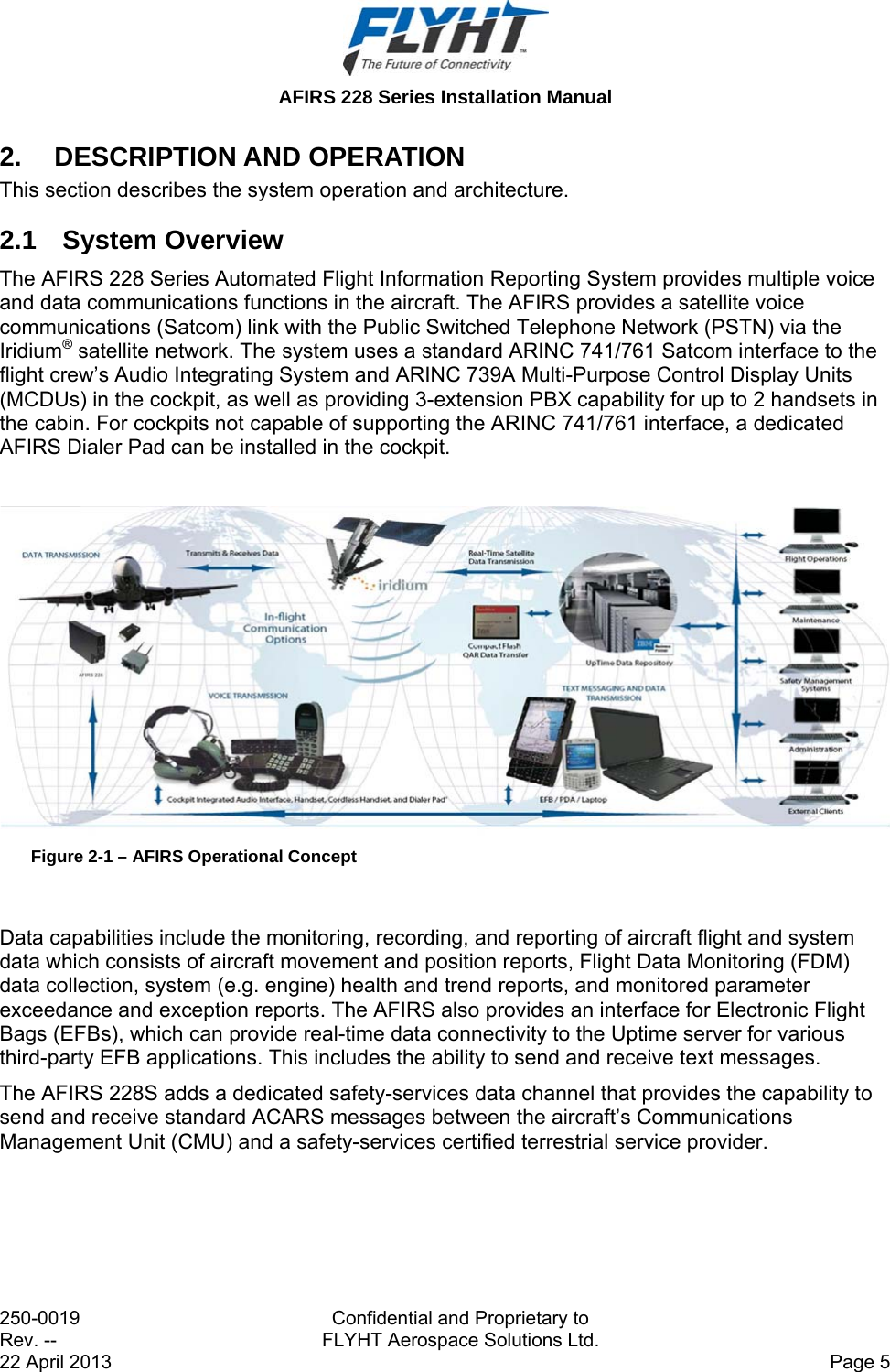
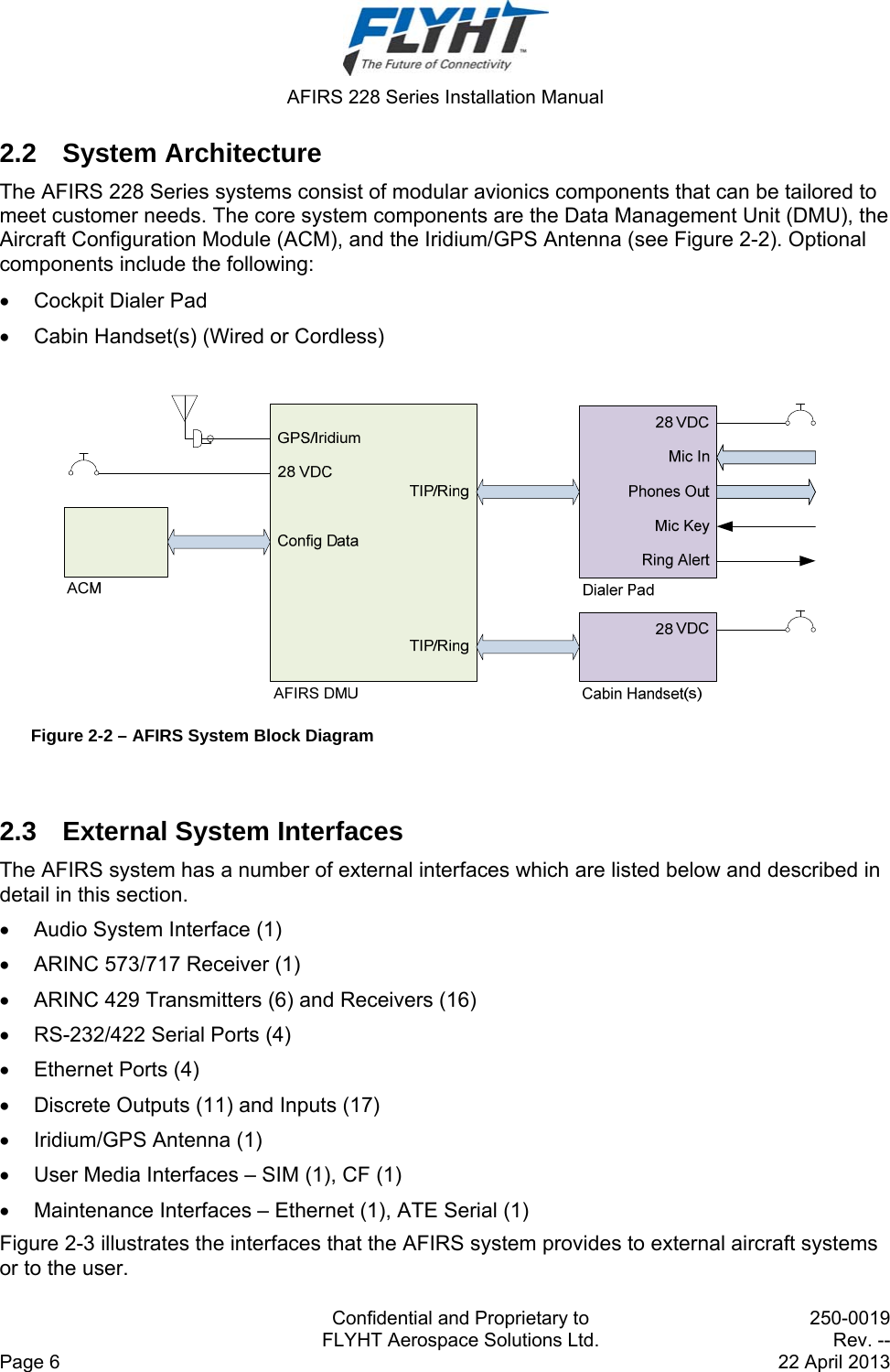
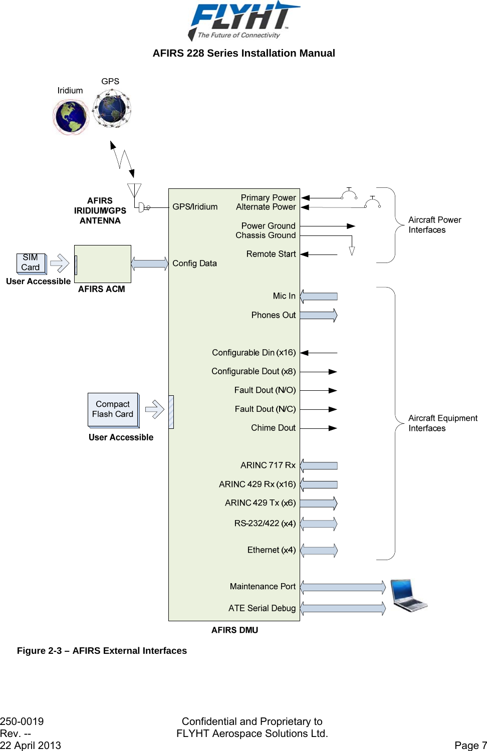
228S User Manual
Manual
Navigation menu
Upload a User Manual
Namespaces
Wiki Guide
HTML
PDF
Info
Views
User Manual
Discussion / Help
Navigation
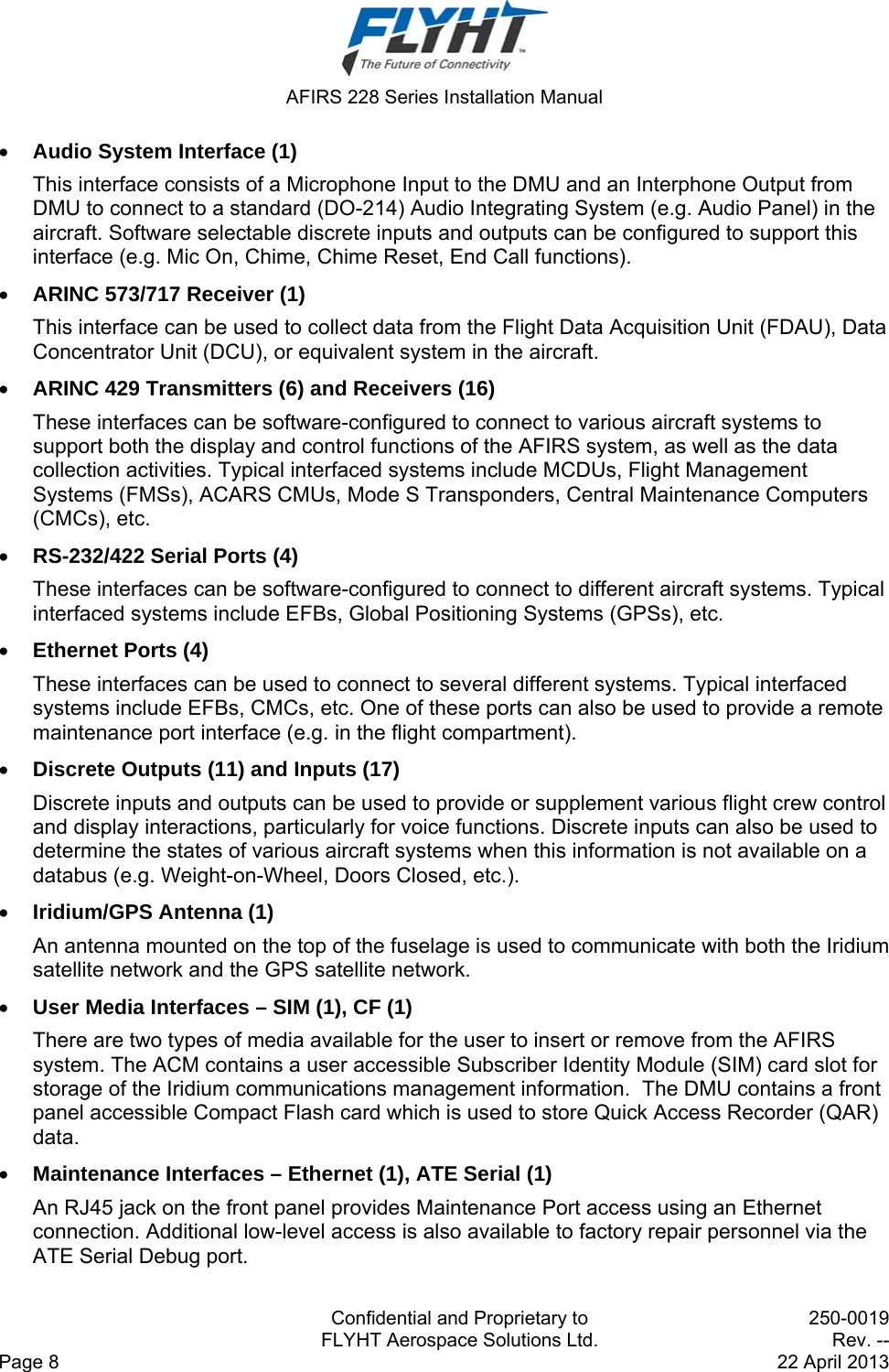
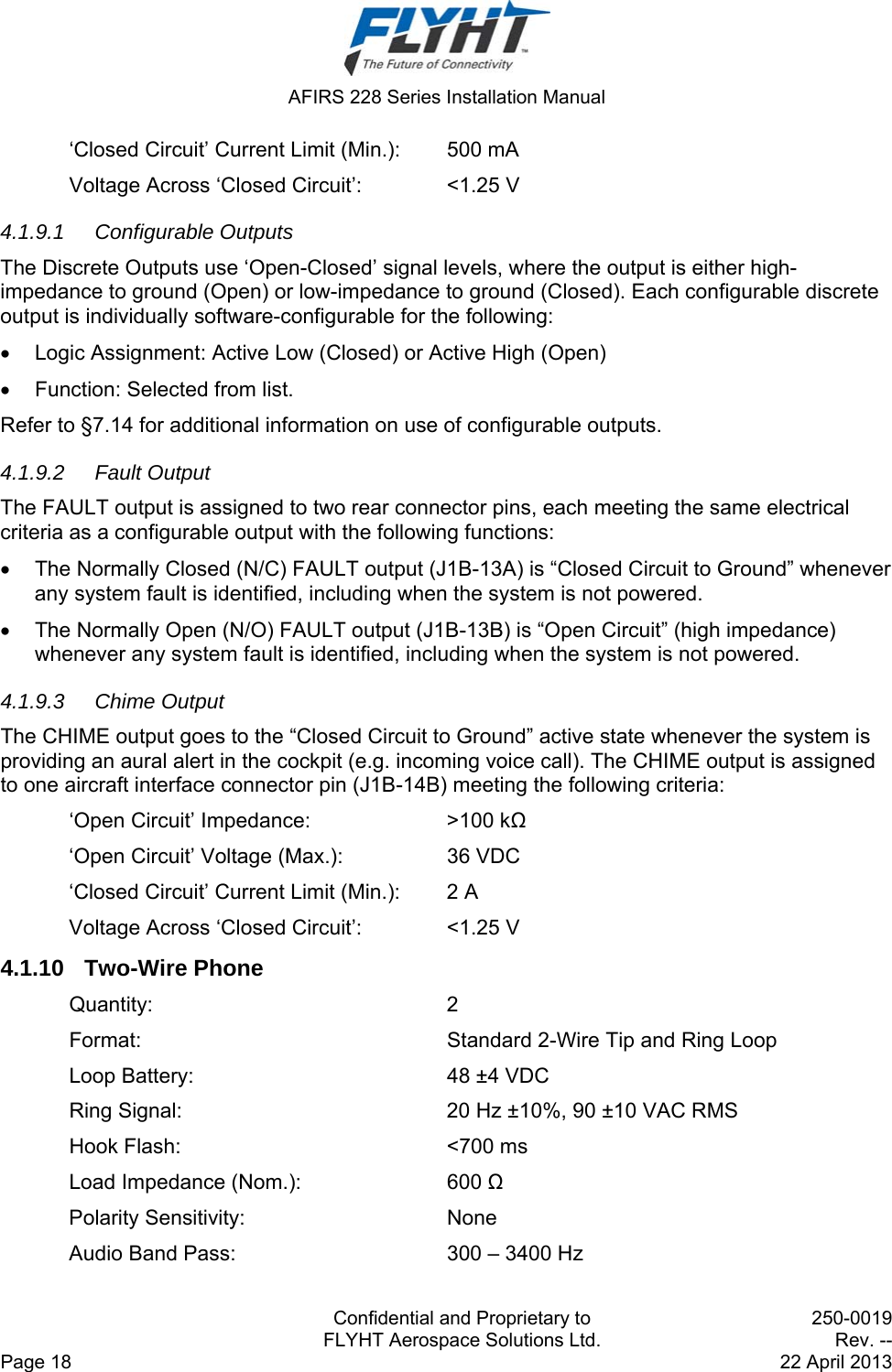
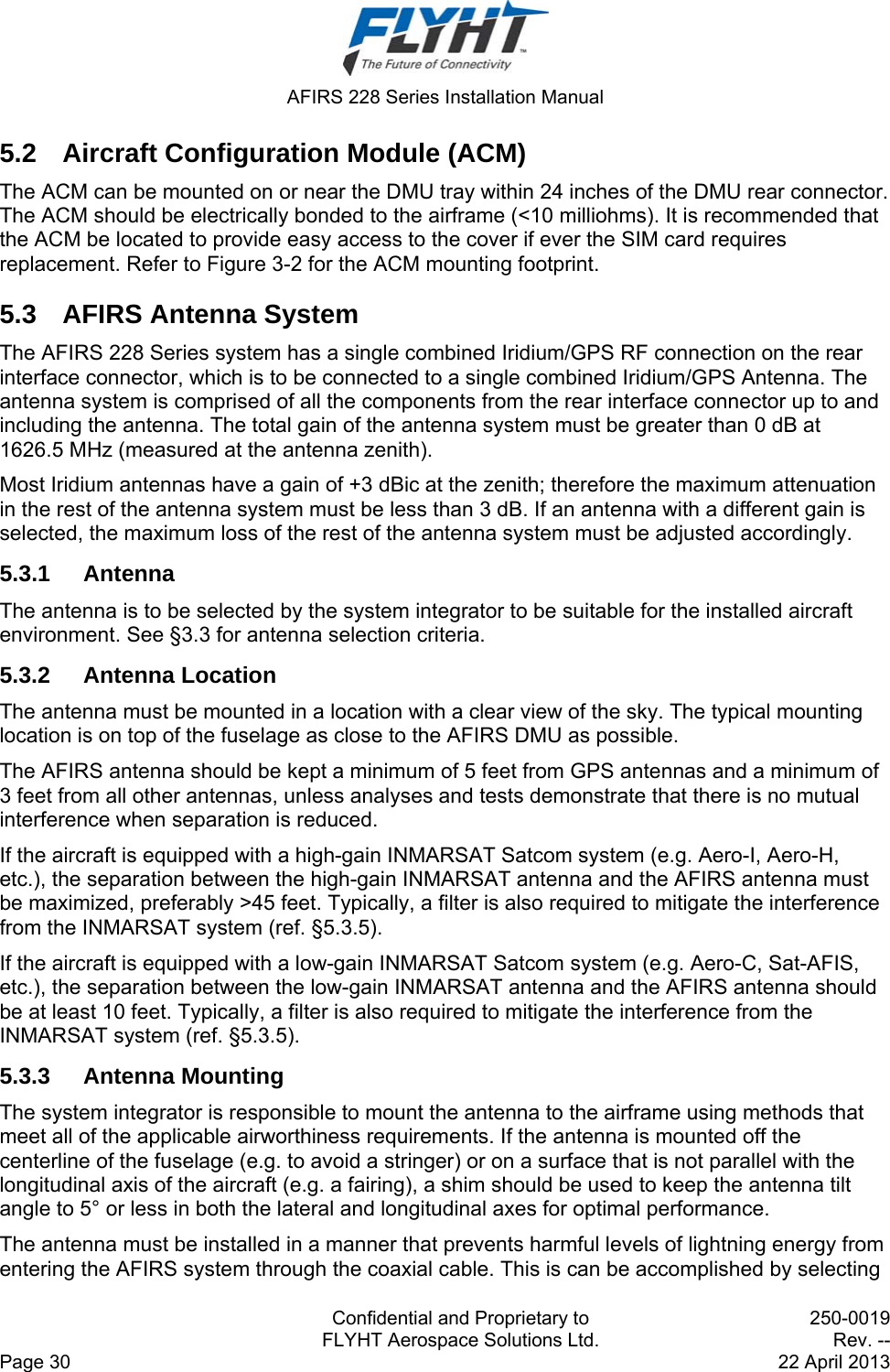
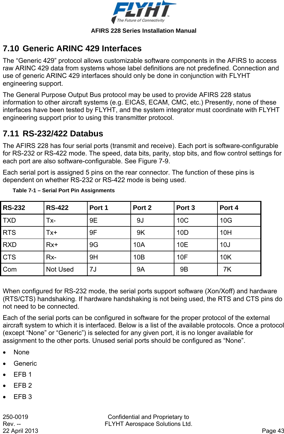
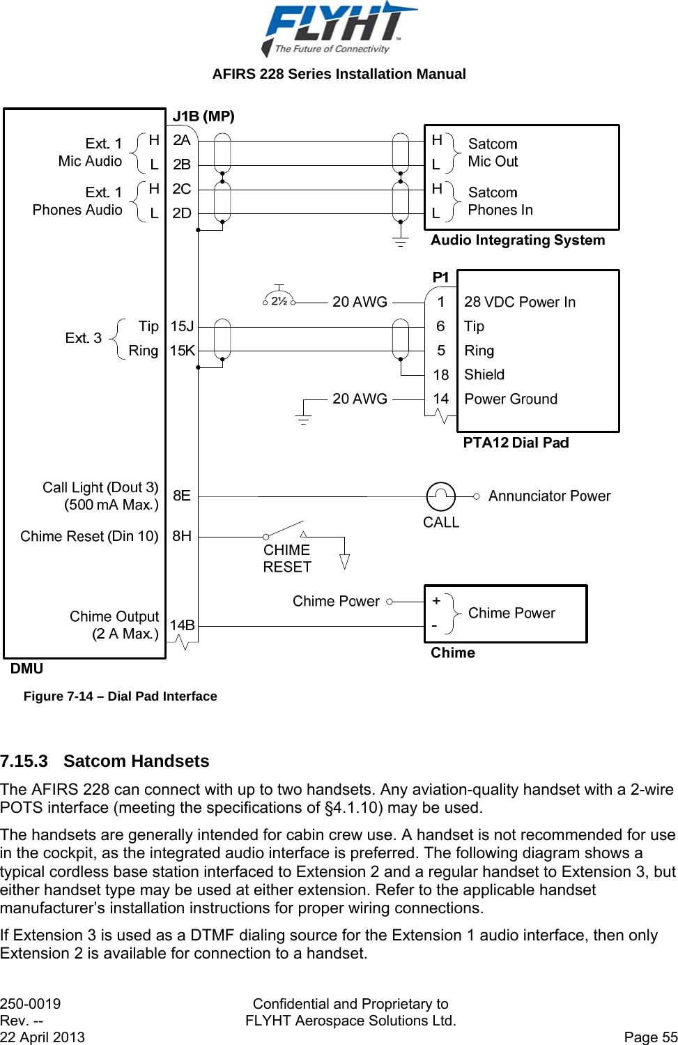
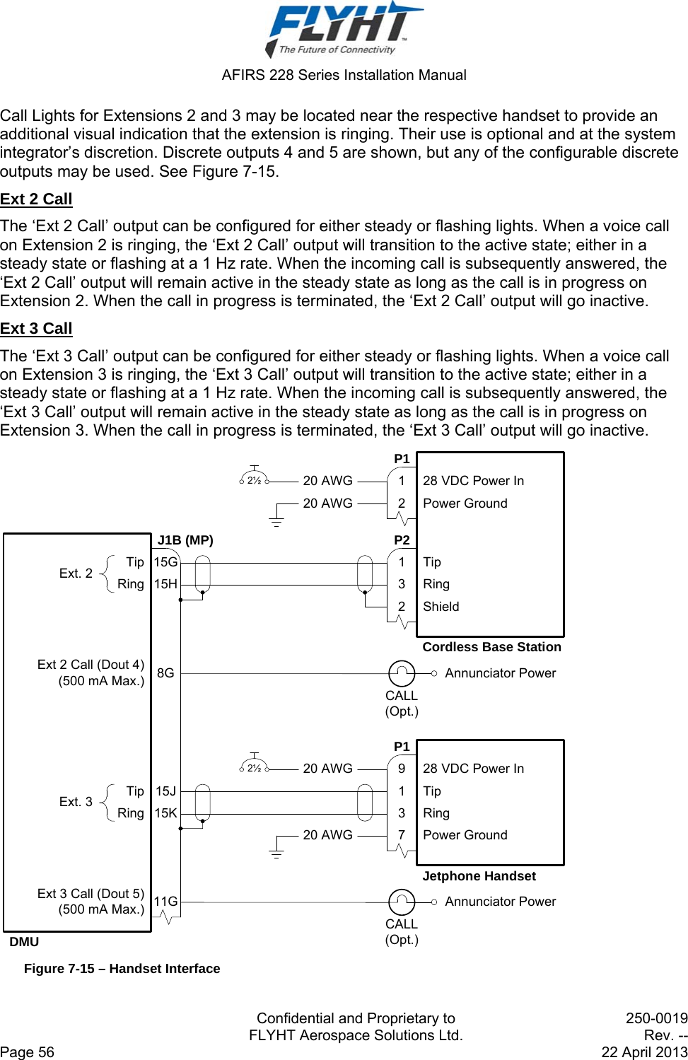
![AFIRS 228 Series Installation Manual Confidential and Proprietary to 250-0019 FLYHT Aerospace Solutions Ltd. Rev. -- Page 10 22 April 2013 Rear Mating Connector: Size 2 ARINC 600 Receptacle Radiall P/N: NSXN2P201S0004 ITT P/N: BKAD2-313-300-04 Maintenance Connector: RJ45 (8P8C) Modular Connector Jack Flash Card: CompactFlash® (Type I or Type II) 3.1.3 Environmental Specifications – AFIRS 228B Temperature (Operating): -55°C to +70°C (Without Iridium Satellite Communication) -40°C to +70°C (With Iridium Satellite Communication) Temperature (Survival): -55°C to +85°C Altitude: 55,000 ft. Vibration: DO-106F Cat. SCL and U2 Humidity: <95% Non-Condensing (DO-106F Cat. A) DO-160F Categories: [(A2)(F2)X]BAD[(SCL)(U2)]XXXXXXZZ(XI)AZ[ZW][ST]MXXXAC Note: Satellite voice and data communications functions in the AFIRS 228B are not operational below -40°C. At elevated temperatures (>60°C), the voice modem has a maximum duty cycle of 60%. 3.1.4 Environmental Specifications – AFIRS 228S Temperature (Operating): -55°C to +70°C Temperature (Survival): -55°C to +85°C Altitude: 55,000 ft. Vibration: DO-160G Cat. SCL and U2 Humidity: <95% Non-Condensing (DO-160G Cat. A) DO-160G Categories: [(A2)(F2)X]BAD[(SCL)(U2)]XXXXXXZZ(XI)AZ[ZW][TT]MXXXAC Note: DO-160G Categories for the AFIRS 228S are as specified by the design. Qualification tests on the AFIRS 228S DMU have not been completed to date.](https://usermanual.wiki/FLYHT-Aerospace-Solutions/228S/User-Guide-2182347-Page-18.png)
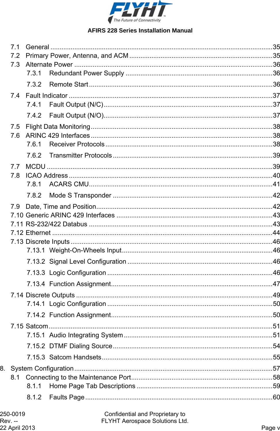
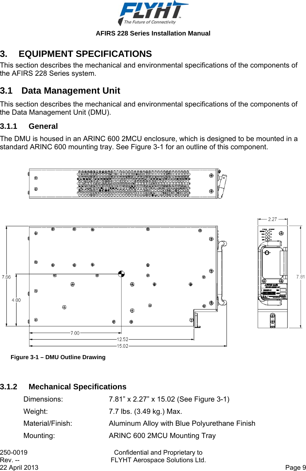
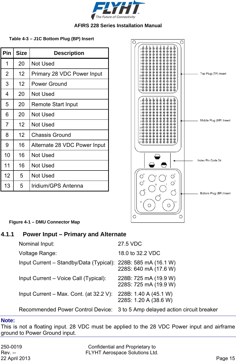
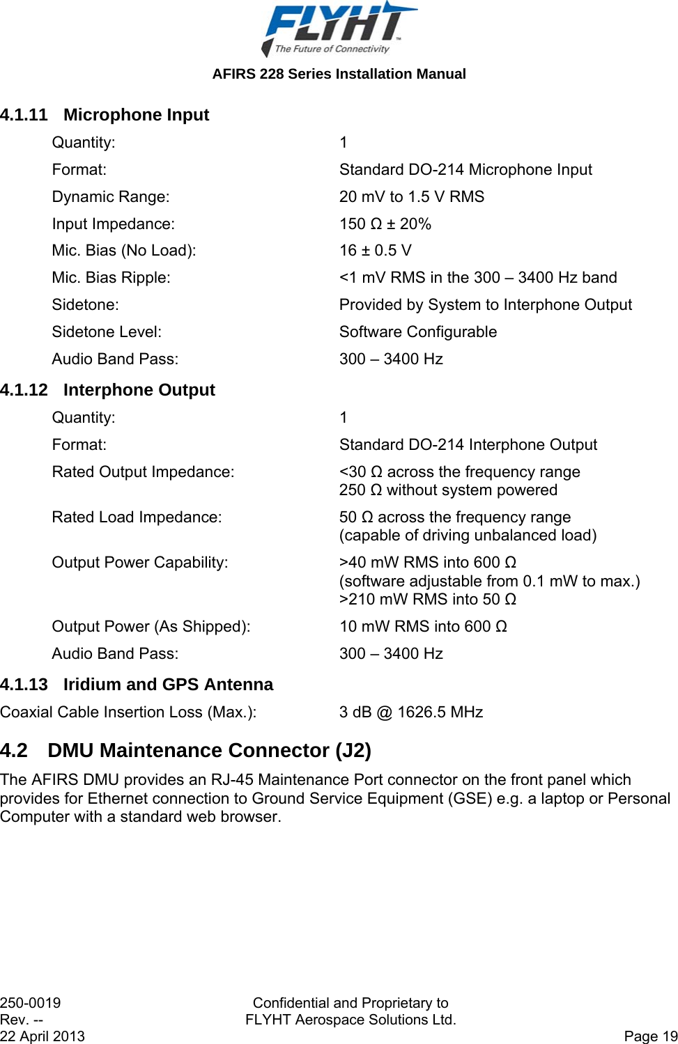
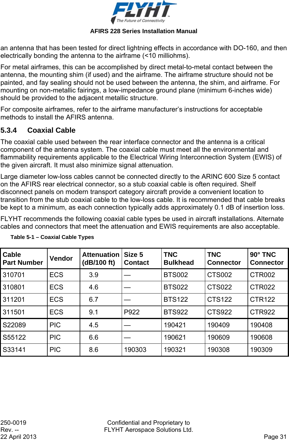
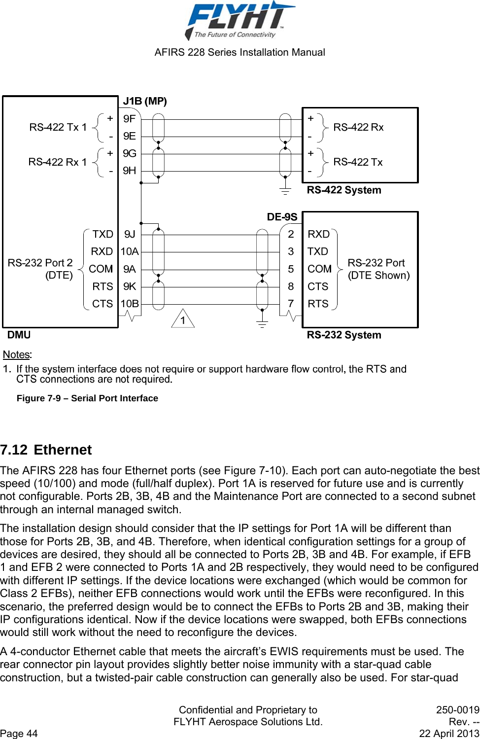
![AFIRS 228 Series Installation Manual 250-0019 Confidential and Proprietary to Rev. -- FLYHT Aerospace Solutions Ltd. 22 April 2013 Page 11 3.2 Aircraft Configuration Module This section describes the mechanical and environmental specifications of the components of the Aircraft Configuration Module (ACM). 3.2.1 General The ACM is housed in small enclosure, which is designed to be mounted within 24” of the DMU rear connector. Typically, the ACM will be mounted on or near the ARINC 600 mounting tray used for the DMU. See Figure 3-2 for an outline of this component. Figure 3-2 – ACM Outline Drawing 3.2.2 Mechanical Specifications Dimensions: 1.75” x 1.75” x 0.63” Weight: 0.2 lbs. (0.09 kg.) Max. Material/Finish: Aluminum Alloy 3.2.3 Environmental Specifications Temperature (Operating): -55°C to +70°C Temperature (Survival): -55°C to +85°C Altitude: 55,000 ft. Vibration: DO-160F Cat. SCL and U2 Humidity: <95% Non-Condensing (DO-160F Cat. A) DO-160F Categories: [(A2)(F2)X]BAD[(SCL)(U2)]XXXXXXZZ(XI)AZ[ZW][ST]MXXXAC](https://usermanual.wiki/FLYHT-Aerospace-Solutions/228S/User-Guide-2182347-Page-19.png)
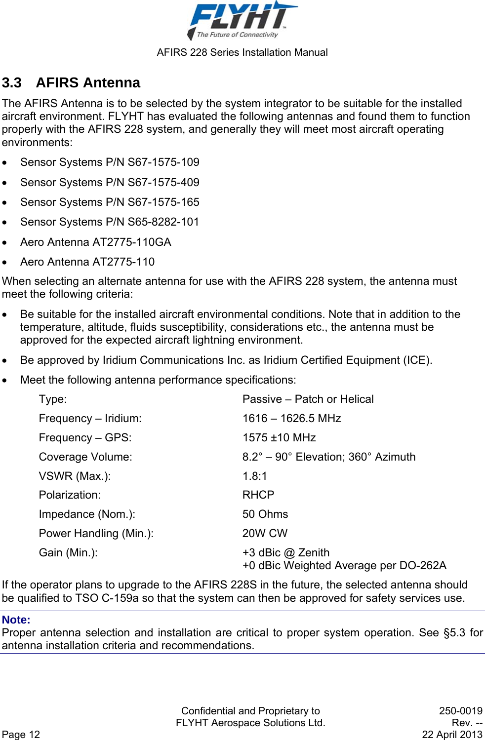
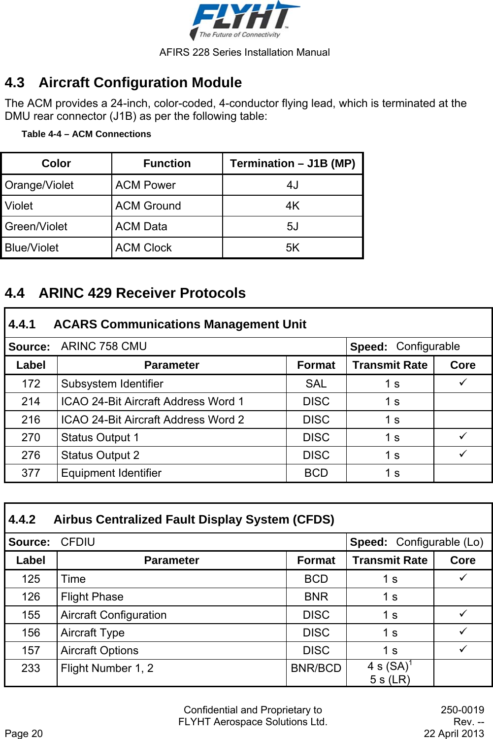
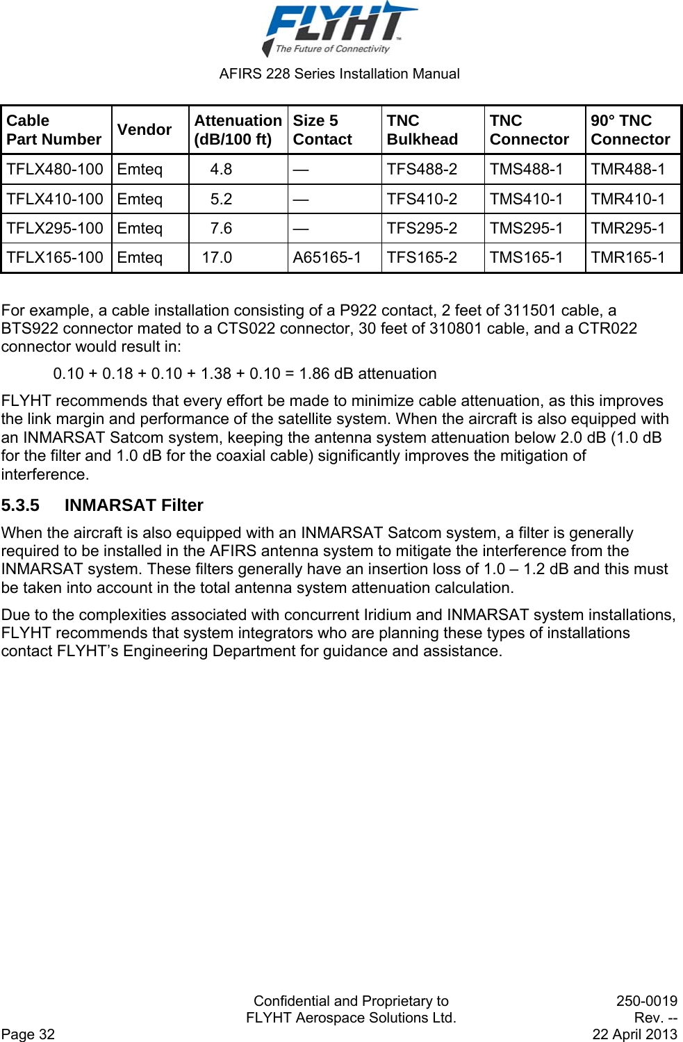

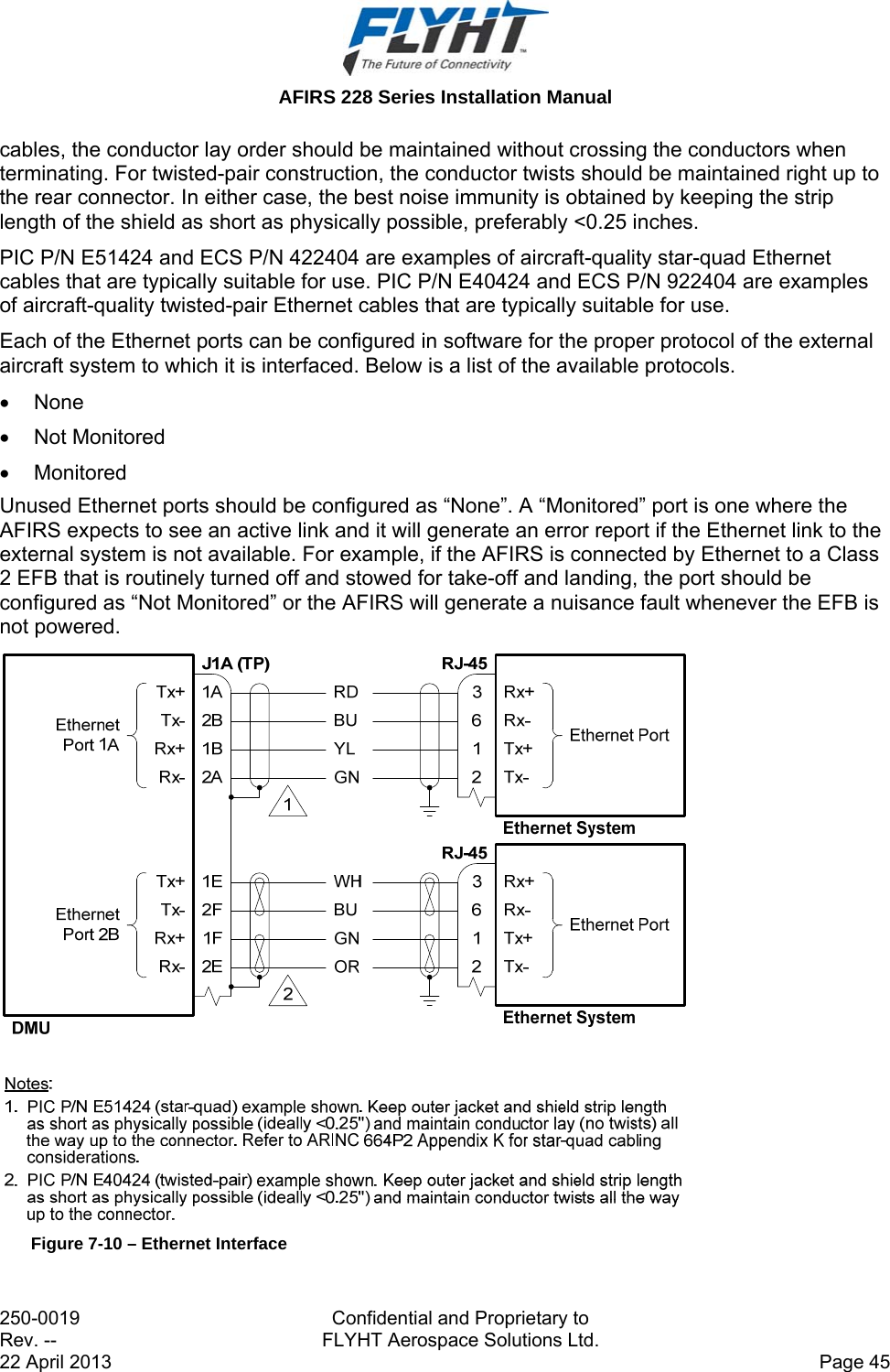
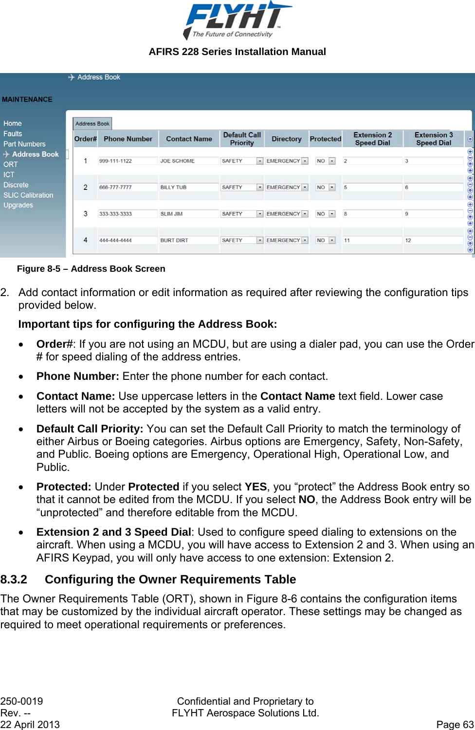
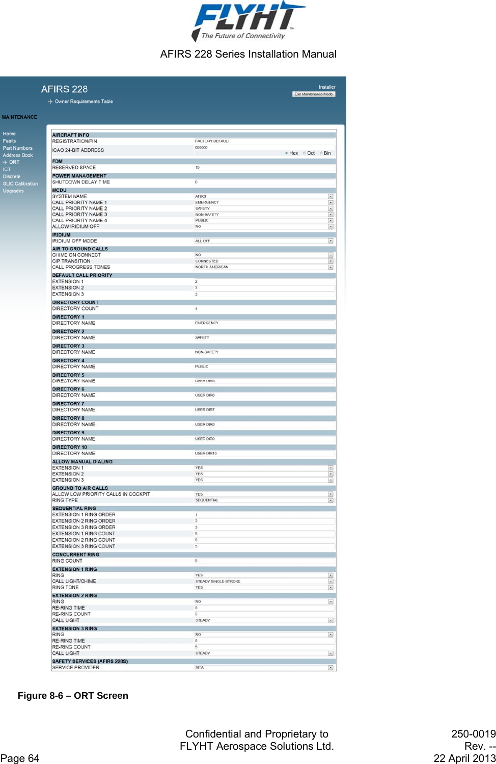
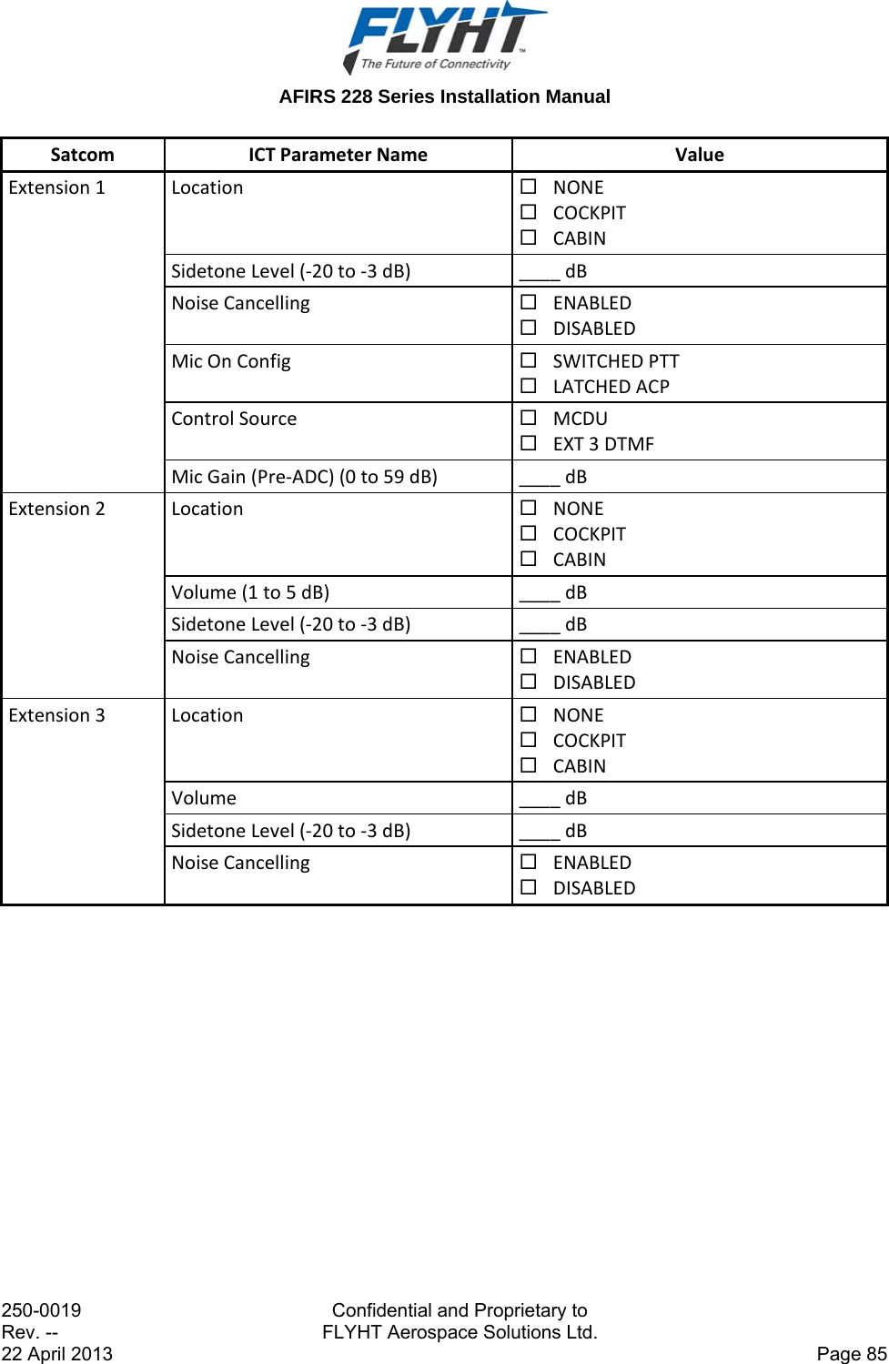
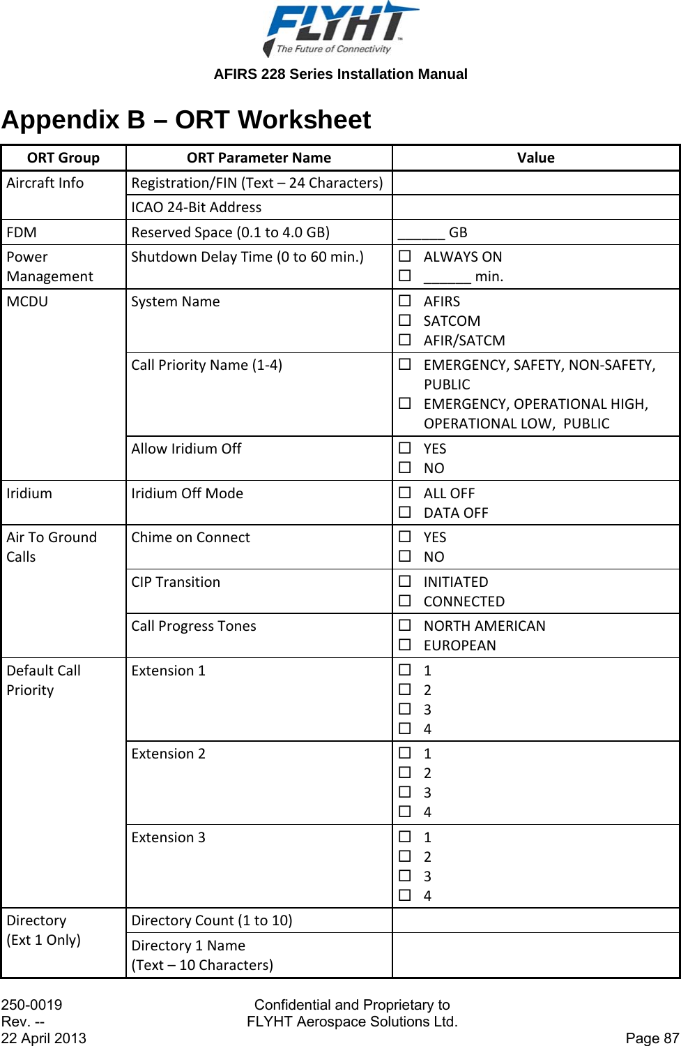
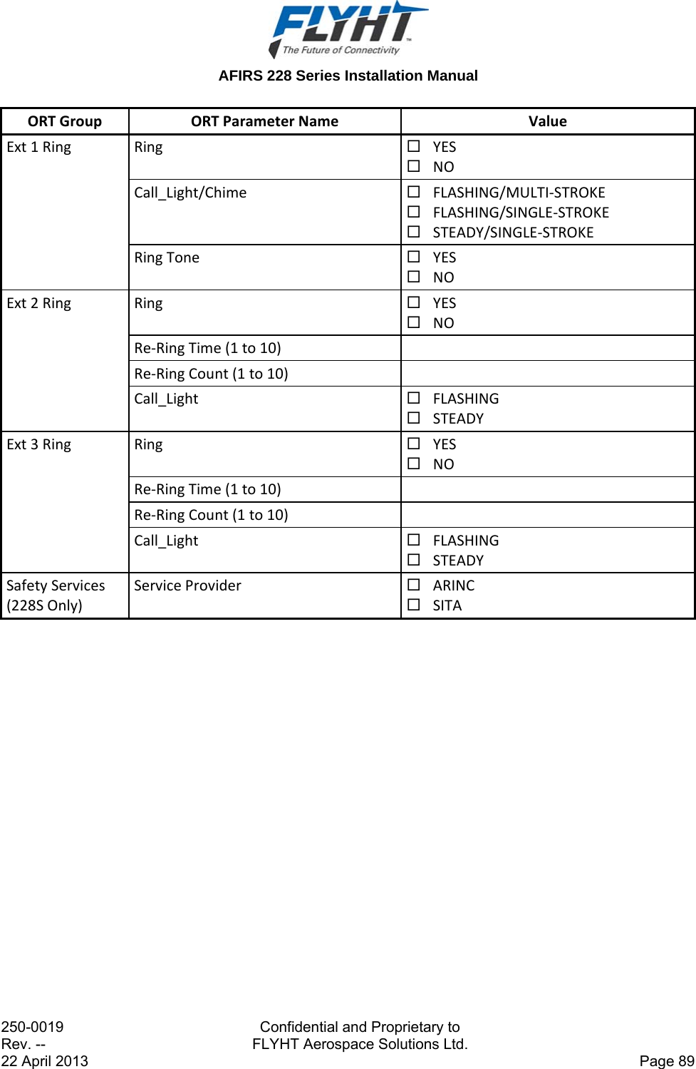
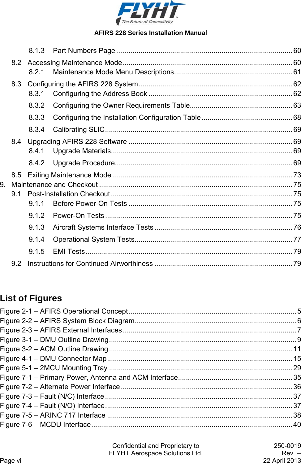
![AFIRS 228 Series Installation Manual 250-0019 Confidential and Proprietary to Rev. -- FLYHT Aerospace Solutions Ltd. 22 April 2013 Page 65 Note: An ORT Configuration Worksheet is provided in Appendix B to assist the operator in selecting and documenting the correct ORT configuration settings. To access and edit the ORT: 1. Click the ORT link on the left-hand side of the screen. The ORT page appears. 2. Enter the AIRCRAFT INFO: REGISTRATION or FLEET IDENTIFICATION NUMBER (FIN). The content of this field is typically used in AFIRS reports that are sent off the aircraft. This entry is a “free text” field that can be up to 24 characters long. The character set for this field is limited to those characters that can be entered and displayed on an MCDU, which are the uppercase alpha-numeric characters plus five special characters: [Space] + - . / 3. Enter the aircraft’s 24-bit ICAO address. The content of this field is typically used in AFIRS reports that are sent off the aircraft. The address can be entered and displayed in hexadecimal, octal, or binary format. Note: If the aircraft installation includes an interface to a system that provides the ICAO address to the AFIRS, this parameter may be automatically updated to the value supplied by the external system. 4. Set the FDM data size reserve space. Space is reserved for FDM data on the CompactFlash card so that other data does not overwrite the FDM data before the operator has had the opportunity to download the FDM data. The default setting is 1.0 GB, but this can be set between 0.1 GB and 4.0 GB as required. 5. Set the POWER MANAGEMENT option. When the AFIRS has power sources connected to both the Main and Alternate power inputs, the SHUTDOWN DELAY TIME sets how long the system will continue to operate on the Alternate power source once the Main power source has been removed. The default is ALWAYS ON. 6. Configure the MCDU options: a) SYSTEM NAME: Enter the preferred MCDU display name for the AFIRS system. The system name that is displayed on the MCDU can be selected from the list shown in Appendix A. The default is AFIRS. b) CALL PRIORITY NAME 1 – 4: Select the label used to identify the four call priorities. The label options can be selected from the sets shown in Appendix A. The default is EMERGENCY, SAFETY, NON-SAFETY, and PUBLIC. c) ALLOW IRIDIUM OFF: The AFIRS system can be configured to provide an ALLOW IRIDIUM OFF selection on the MCDU. The default is NO; if set to NO, Iridium activity will not display on the MCDU. If you select YES, the IRIDIUM activity does appear on the MCDU. This setting affects only the MCDU functionality. If the system is configured to](https://usermanual.wiki/FLYHT-Aerospace-Solutions/228S/User-Guide-2182347-Page-73.png)
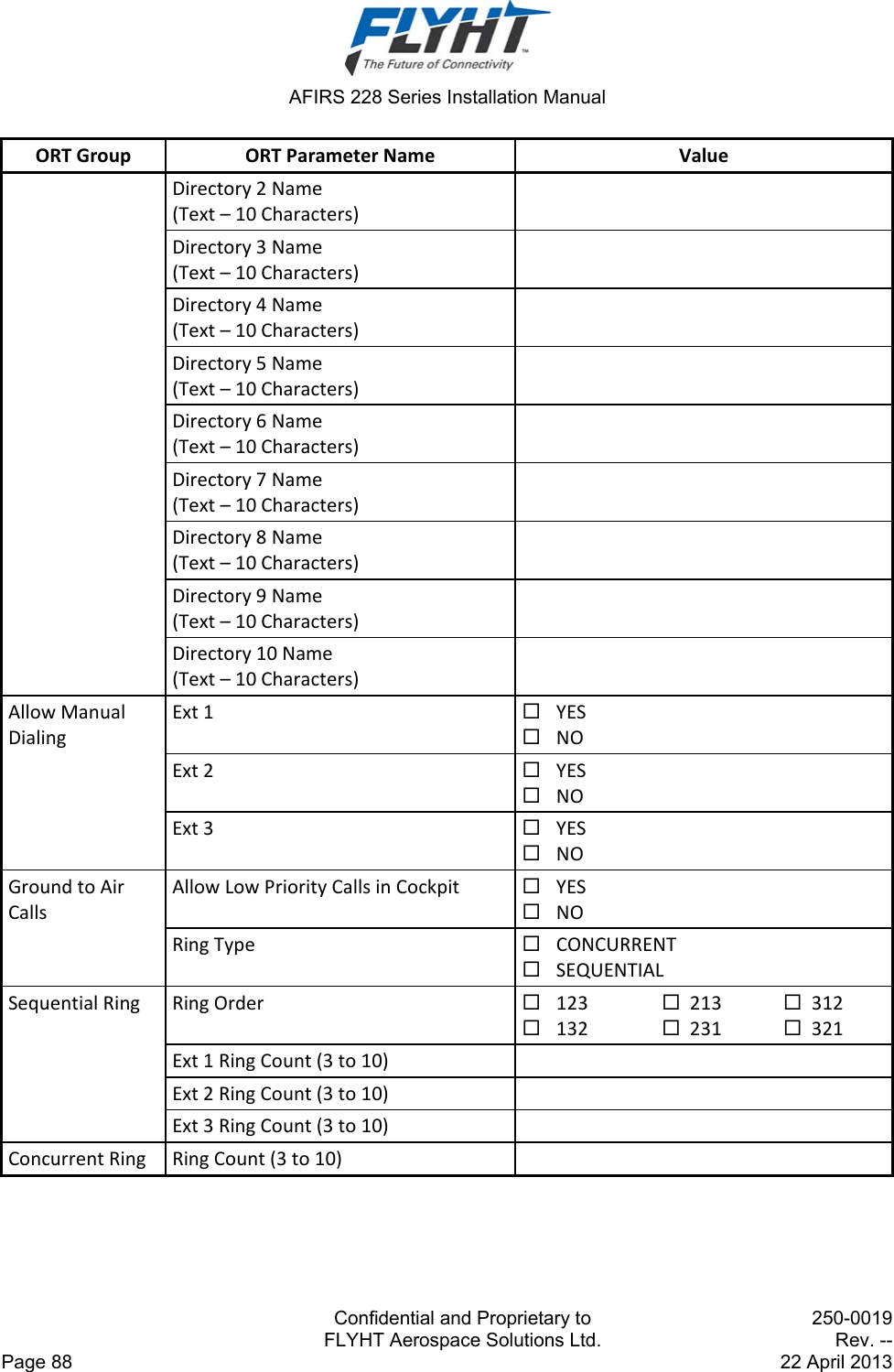
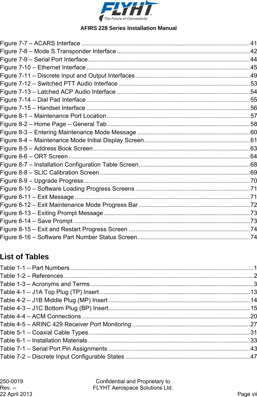
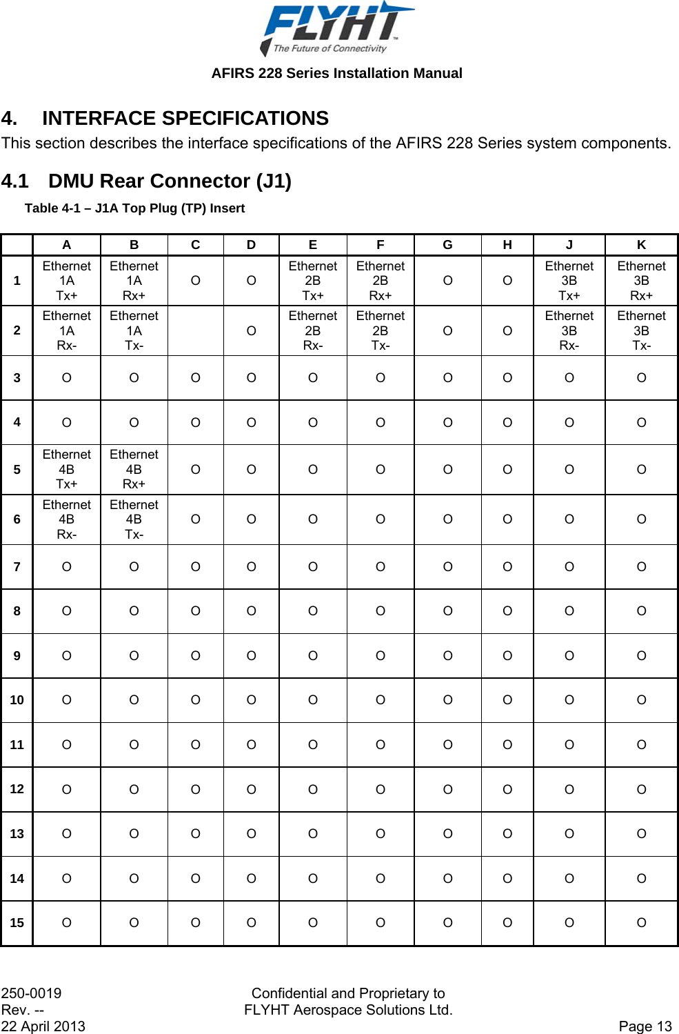
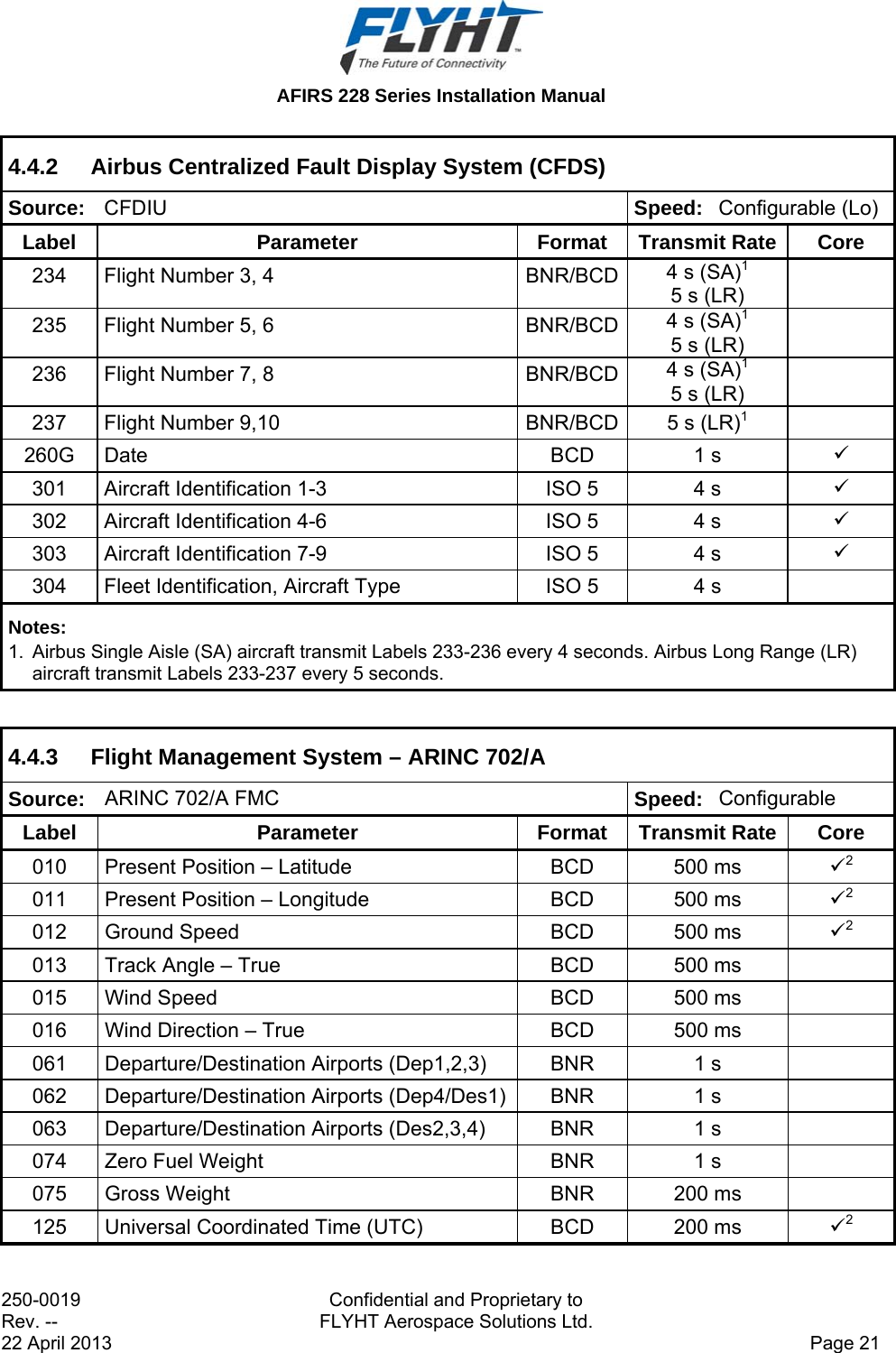
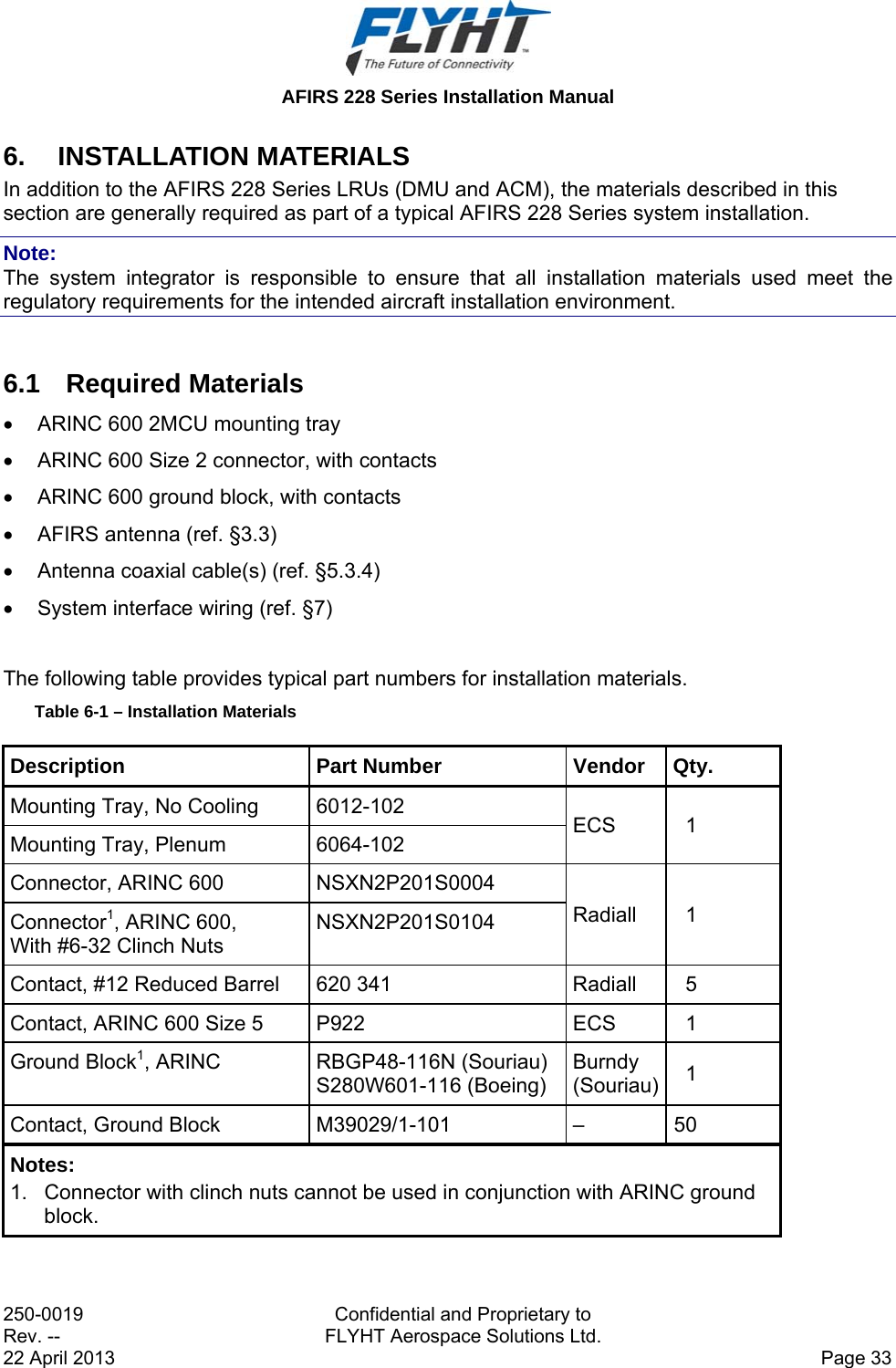
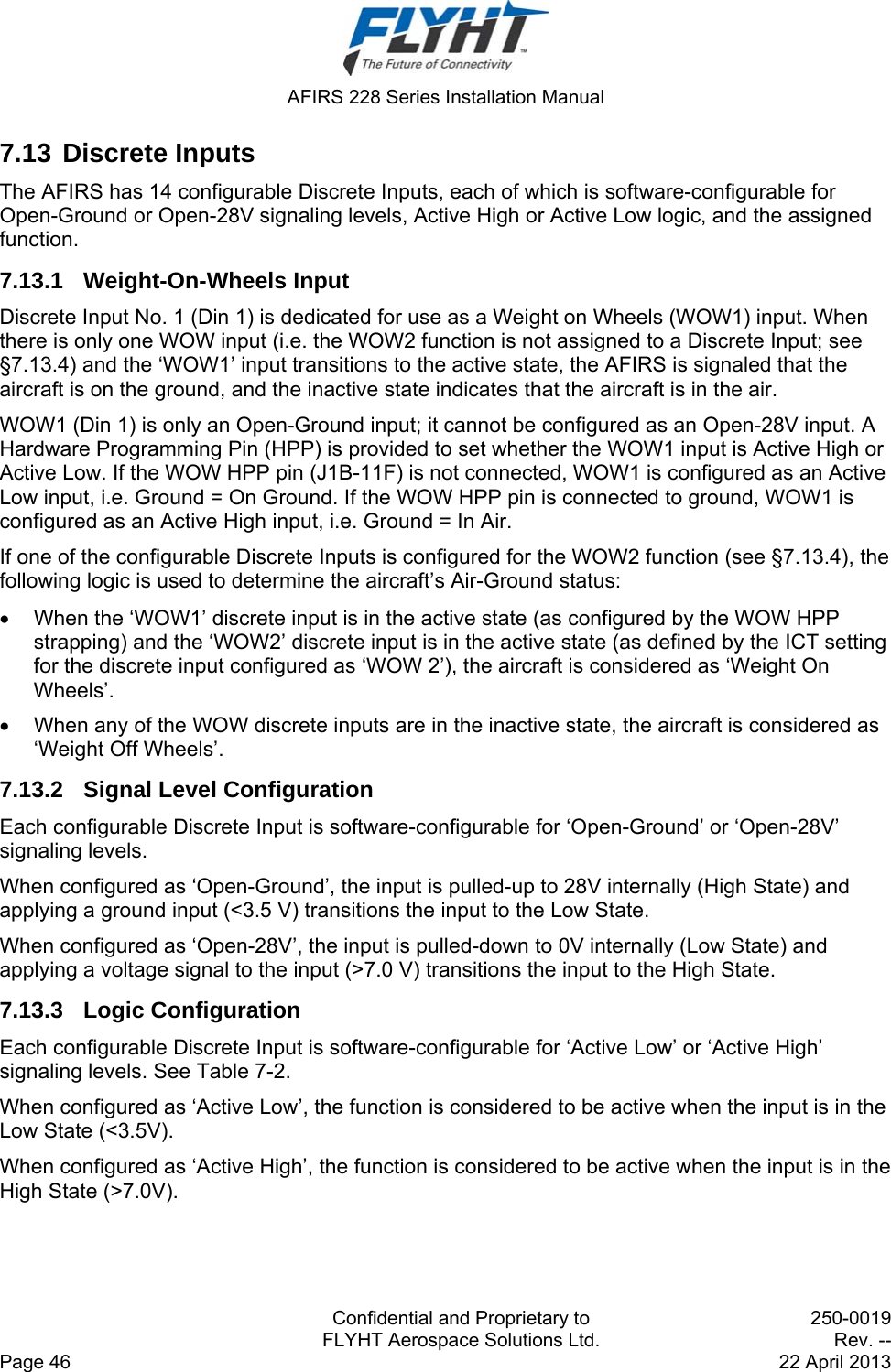
![AFIRS 228 Series Installation Manual Confidential and Proprietary to 250-0019 FLYHT Aerospace Solutions Ltd. Rev. -- Page 66 22 April 2013 provide an ALLOW IRIDIUM OFF discrete input, the function of that discrete input is unaffected by this configuration setting. 7. Select the IRIDIUM data reporting options. When the AFIRS system is in the IRIDIUM OFF MODE, the system can be configured to either disable only data reporting to the MCDU, or to disable all Iridium satellite voice and data transmissions. The default is ALL OFF. 8. Set the options for AIR TO GROUND CALLS. a) CHIME ON CONNECT: The AFIRS system can be configured to trigger the chime output when an Air-to-Ground call connects. The default is NO. b) CIP TRANSITION: The AFIRS system can be configured to communicate (and display) the Call in Progress (CIP) transition state to the MCDU either when an Air-to-Ground call is initiated, or when it is connected. The default is CONNECTED. c) CALL PROGRESS TONES: The AFIRS system can be configured to use either CALL PROGRESS TONES that are North American or European. The default is NORTH AMERICAN. 9. Configure the DEFAULT CALL PRIORITY. The default call priority can be configured for Extension 1. The default setting is 2. Priority 1 is reserved for emergencies. The default call priority can be configured for Extensions 2 and 3. The default setting is 3. Note: The call priority for any individual call dialed from an MCDU can be changed at the time of placing the call. The call priority for any outgoing calls dialed using a Dual Tone Multiple Frequencies (DTMF) dial pad will be set to the priority configured in the ORT. The call priority for any outgoing calls dialed from Extension 2 or 3 is set to the priority configured in the ORT. Extensions 2 and 3 should not be set to priority 1 unless they will only ever be used to place an Emergency call. Placing an Emergency call can trigger ATC alarms and emergency responses, so extreme caution should be exercised whenever an extension is configured to allow making an Emergency call. 10. Configure the DIRECTORY COUNT. The speed dial entries for Extension 1 are grouped into directories. The AFIRS system can be configured to provide between 1 to 10 different directories. The default setting is 4. 11. Name DIRECTORY 1, 2, 3, 4, 5, 6, 7, 8, 9 & 10. The name of each directory is configurable. The DIRECTORY NAME is a “free text” field that can be up to 10 characters long. The character set for this field is limited to those characters that can be entered and displayed on an MCDU, which are the uppercase alpha-numeric characters plus five special characters; [Space] + - . /](https://usermanual.wiki/FLYHT-Aerospace-Solutions/228S/User-Guide-2182347-Page-74.png)