FLYSKY RC MODEL TECHNOLOGY FLYSKYI6X 6CH radio control system User Manual
FLYSKY RC MODEL TECHNOLOGY CO., LTD 6CH radio control system
UserManual.wiki
>
FLYSKY RC MODEL TECHNOLOGY
>
FLYSKYI6X User Manual
User Manual
Navigation menu
Upload a User Manual
Namespaces
Wiki Guide
HTML
PDF
Info
Views
User Manual
Discussion / Help
Navigation
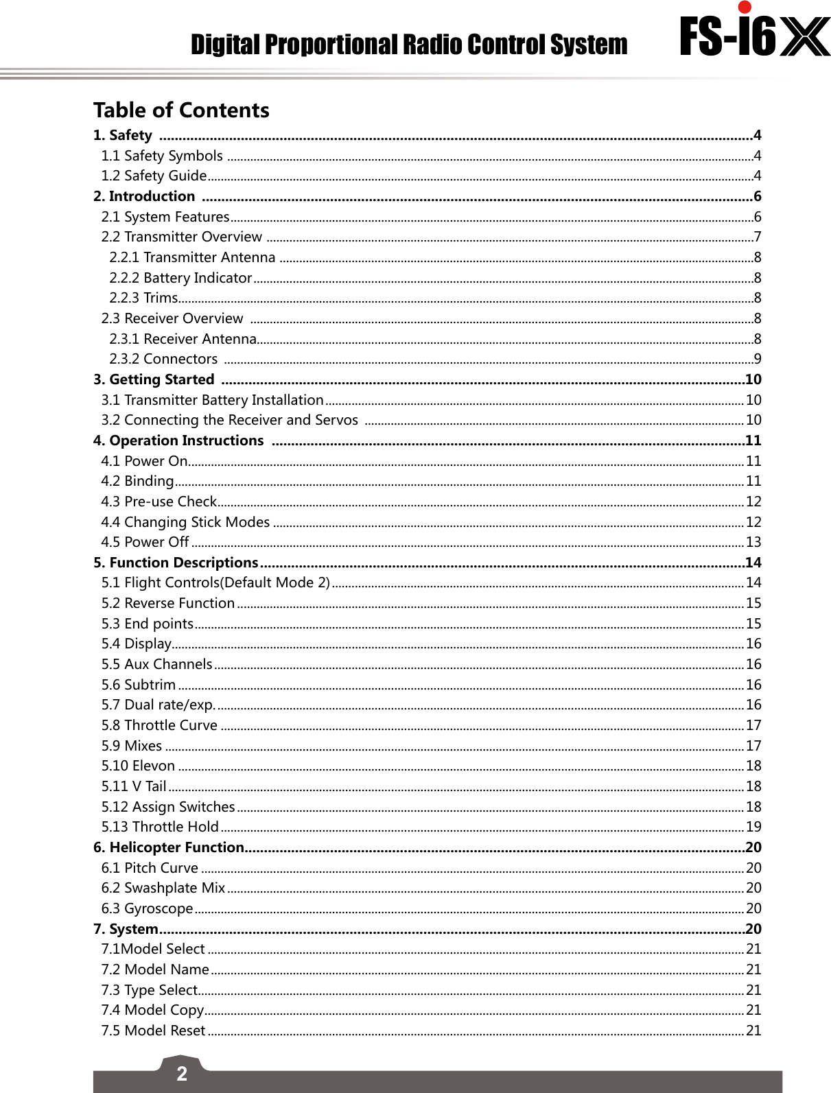
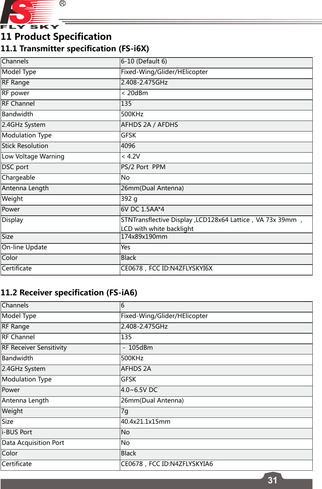
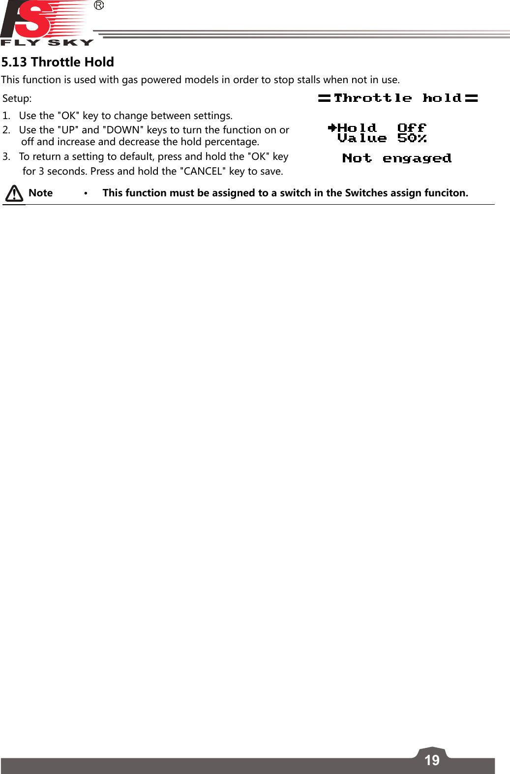
![16Digital Proportional Radio Control System FS-l6 5.4 DisplayThis function displays the model's channel output in real time.Warning• Make sure the model engine is powered off while the test function is activated. If powered on, it will rev up and cause unexpected results.Danger • Make sure the model does not go out of range.Setup:1. Hold the "OK" key to enable channel scrub mode. In this mode the channels will sweep though their entire range of motion.2. Press "CANCEL" key to exit. 5.5 Aux ChannelsThe auxiliary channels function can be used to assign switches to extra channels to control additional part of a model such as landing gear or lights. Setup:1. Press the "OK" to change channels. 2. Use the "UP" and "DOWN" keys to select a source (Switch ,Knob or None).3. Hold the "CANCEL" key to save and return to the previous menu.5.6 SubtrimSubtrim changes the center point of the channel. For example, if a models rudder is slightly out of alignment, the subtrim could be used to fix this. Setup:1. Press the "OK" to change channels. 2. Use the "UP" and "DOWN" keys to change the subtrim position. 3. Hold the "CANCEL" key to save and return to the previous menu.4. To return to default settings press and hold the "OK" key for 3 seconds. until the channel returns to the center.Press and hold the "CANCEL" key to save.5.7 Dual rate/exp.Thedualrate/exp.functiononlyappliestochannels1、2、4.[Dual Rate]: Dual Rate reduces or increases the difference between the highest and lowest possible value, for example if applied to the rudder, (set to a throw of 10cm) before changing the settings, when you move your stick to 1/2 you would get 5cm rudder movement, if you move the stick 1/4 of the way, the](https://usermanual.wiki/FLYSKY-RC-MODEL-TECHNOLOGY/FLYSKYI6X/User-Guide-3044503-Page-17.png)
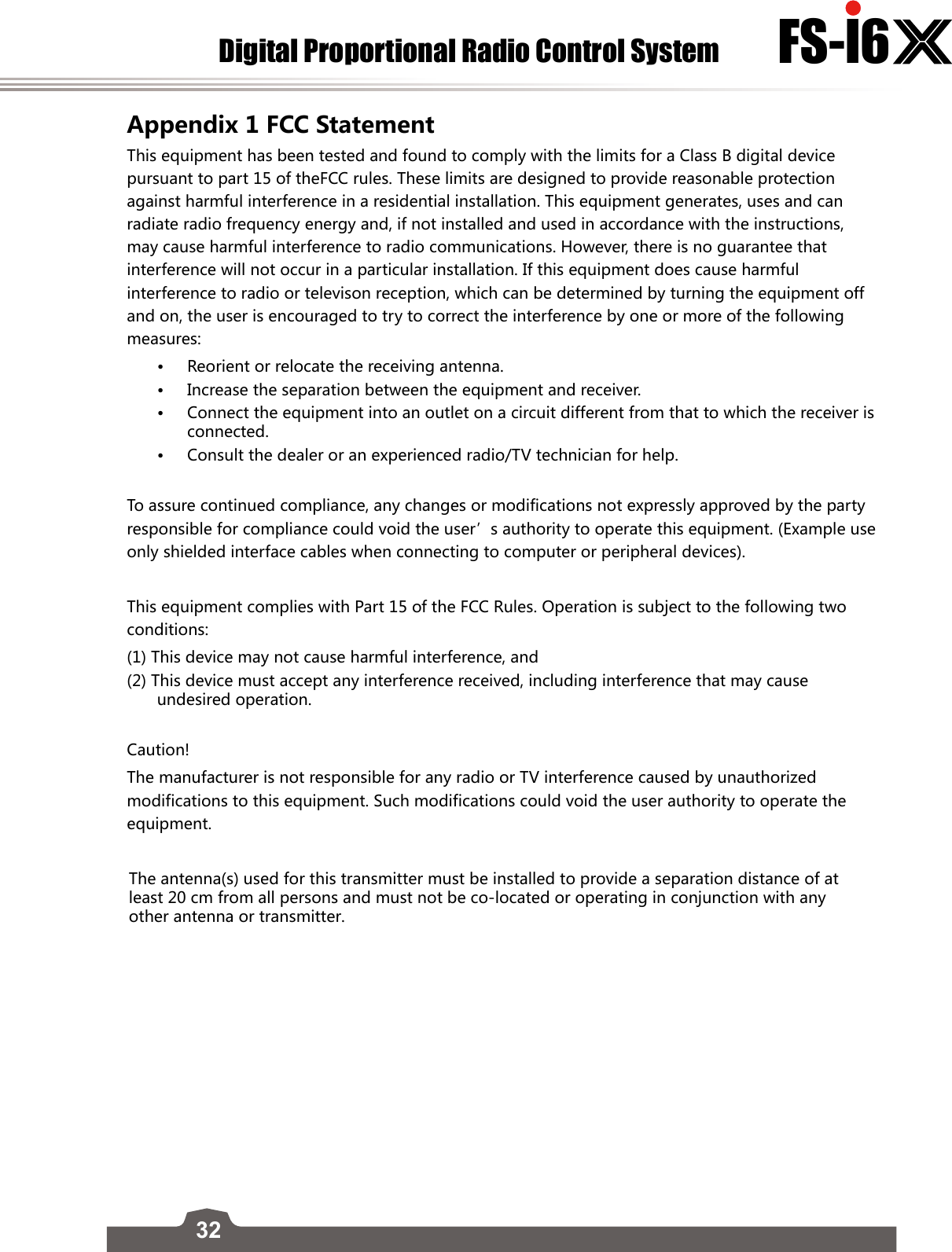
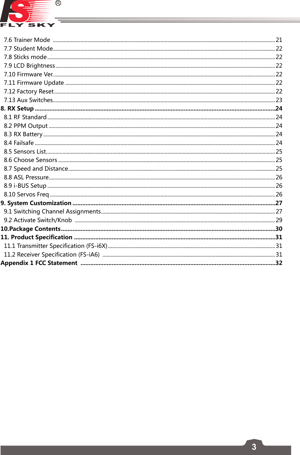
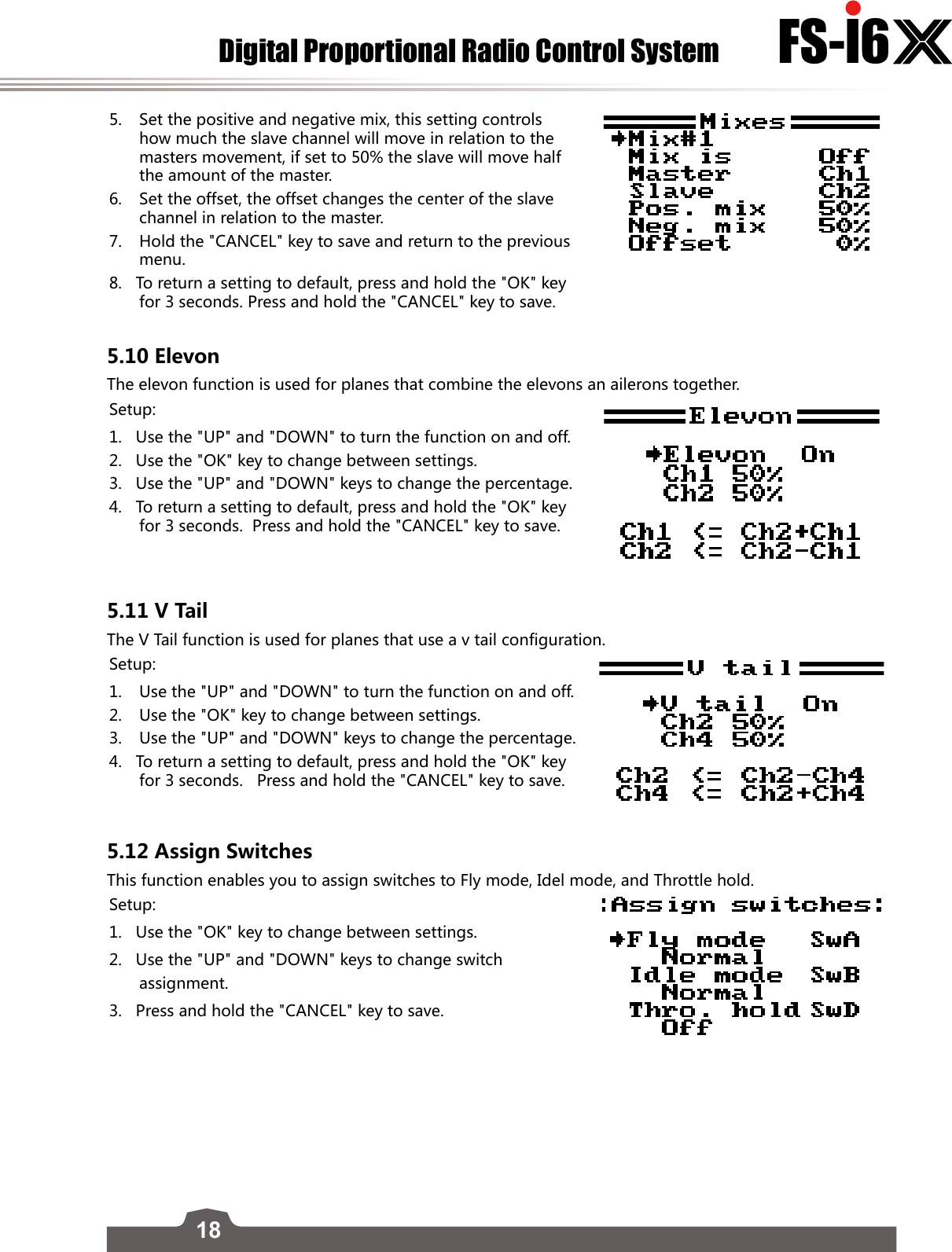
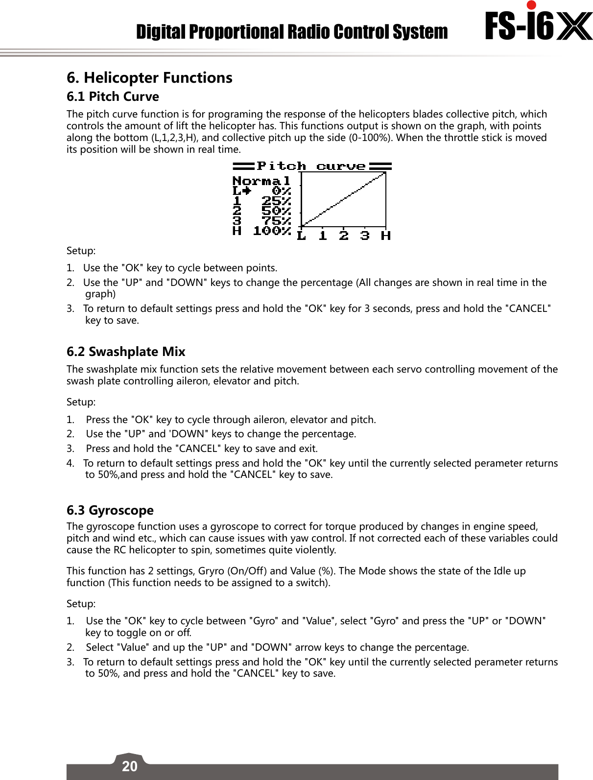
![17FS-l6 rudder will move 2.5cm, so at 100% there is a direct, linear relationship of stick movement and surface movement. If a setting of 50% is entered then moving the stick all the way in one direction will only give 1/2 of the surface movement and 1/2 stick movement will only produce 1/4 surface movement, this has the effect of reducing how responsive the rudder is when the stick is moved, effectively reducing the range of movement available to the servo. This function is usually assigned to a condition so that it can be turned on and off during flight. [Exp. (Exponential)]: Exponential changes the relationship between stick movement and surface movement by creating a curve, when in use the stick movement and surface movement are no longer linear so the stick has a different response in different at different positions. For example this is useful when needing less reaction during a take-off but more reaction when in the air.Setup:1. Press the "OK" to change between settings. 2. Use the "UP" and "DOWN" keys to change the channel/rate/exp depending on the selected setting. 3. Hold the "CANCEL" key to save and return to the previous menu.4. To return a setting to default, press and hold the "OK" key for 3 seconds. Press and hold the "CANCEL" key to save. 5.8 Throttle Curve This function enables the user to adjust the ratio between stick and servo movement using a linear line or non-linear curves. This is useful when wanting to change how the throttle reacts at between different stick positions, for example having a smaller throttle change when the stick is between 0-30%, then a larger throttle change between 30% and 100%. If your models throttle is not linear, it is also possible to use this function to create a more linear movement. This function uses 5 points to change the throttle curve, L being the low and H being the high. Setup:1. Press the "OK" to change between points. 2. Use the "UP" and "DOWN" keys to change point position. 3. Hold the "CANCEL" key to save and return to the previous menu.4. To return a setting to default, press and hold the "OK" key for 3 seconds. Press and hold the "CANCEL" key to save.5.9 MixesThis function is used to create a mix between channels. For example if at low throttle some automated flap movement was desired then it is possible to create a mix to do this. This system can have up to 3 different mixes. Setup:1. Use the "UP" and "DOWN" keys to select a mix.2. Use the "OK" key to change between settings.3. Select a master channel, this channel will control the slave channel.4. Select a slave channel to be controlled by the master.](https://usermanual.wiki/FLYSKY-RC-MODEL-TECHNOLOGY/FLYSKYI6X/User-Guide-3044503-Page-18.png)
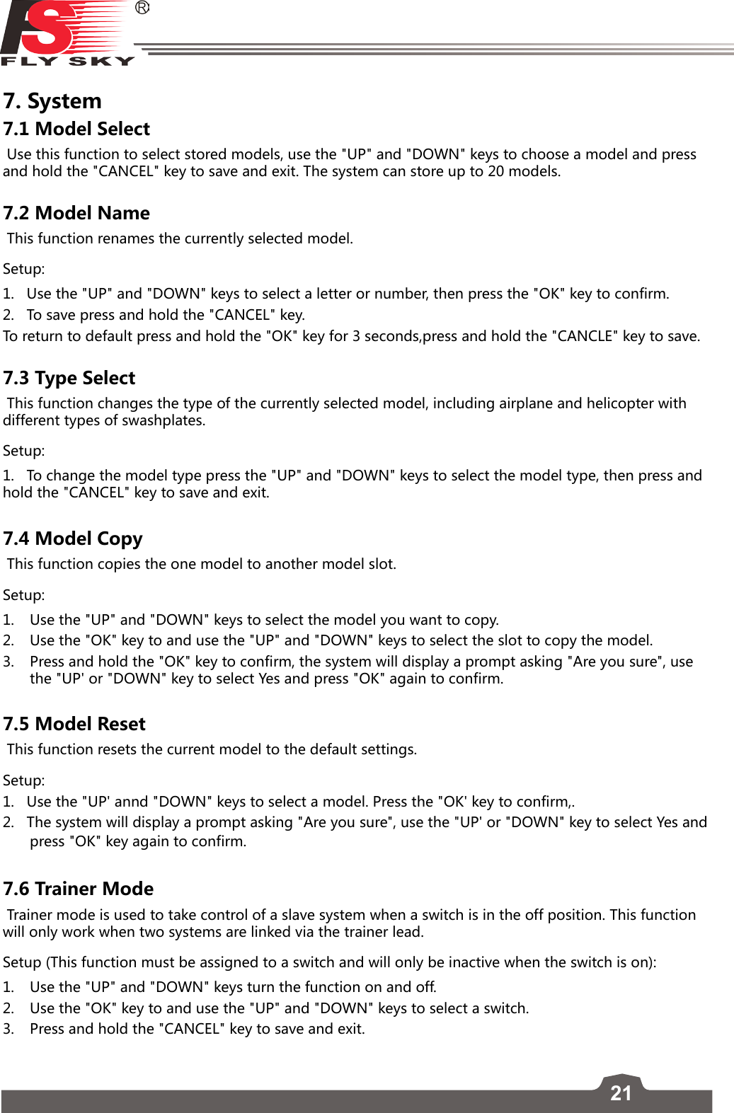
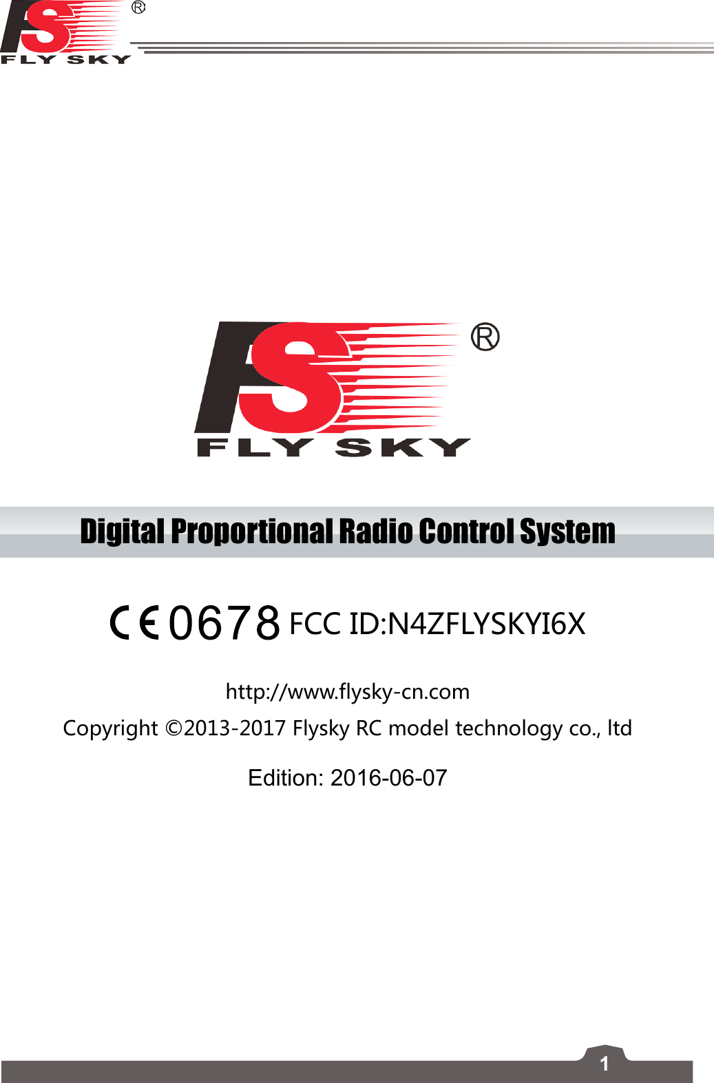
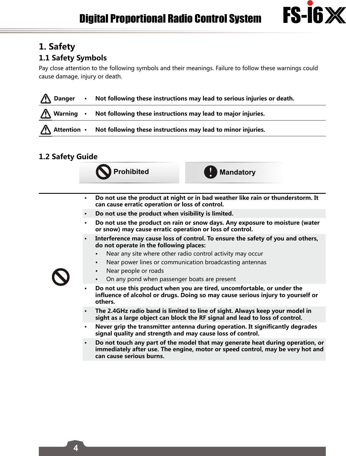
![24Digital Proportional Radio Control System FS-l6 8 RX Setup8.1 RF StandardThis menu allows you to change the communication protocol for the transmitter. The available protocols are:RF Protocol ReceiverAFHDS R9B,R6B,R6C,GR3E,GR3FAFHDS 2A A3, A6,X6, iA4B, iA6, iA6B, iA10, iA10BTo Switching Between AFHDS 2A and AFHDS:1. First navagate to the system menu by pressing and holding the "OK" key until the main menu opens, select "System Setup" by pressing the "OK" key again. 2. Use the "DOWN" key to navagate to "RX setup" and press the "OK" key again to enter, then press the "OK" key one more time to select RF Standard. 3. The system will display a prompt asking if you are sure, use the "UP" or "DOWN" key to select yes and press "OK". 4. Then use the "UP" or "DOWN" key to select the desired RF standard and press and hold the "CANCEL" key for until the system returns to the previous menu to save.5. Use the "UP" and "DOWN" keys to select a mode then press and hold the "CANCEL" key to save and exit. 8.2 PPM OutputPPM is capable of transferring all channels through one physical output. When [RX PPM output] is checked, the receiver outputs PPM on CH1 output and the other outputs are disabled.To turn the function on press the "UP" or "DOWN" keys to turn the function on then press and hold the "CANCEL" key to save and exit. 8.3 RX Battery This function is used to change the battery monitor settings. This function can be switch to an external or internal sensor. There are 4 settings:[External sensor/ Internal Sensor]: The system has its own voltage sensor however it is possible to change to an external sensor. [Low]: Sets the low battery voltage, see your batteries user manual to set this setting. [Alarm]: Sets the voltage level at which the system will allert the user if the battery gets too low. [High]: Sets the voltage for the battery if it is full. Note • These settings affect how the system shows battery levels, if the high and low are incorrect the systems battery display will not be reliable. 8.4 Failsafe This function is used to protect the models and users if the receiver loses signal and therefore is no longer controllable. All channels are listed in the failsafe menu. [Off] means that in case of a loss of signal, the corresponding servo will keep its last received position. If it displays a percentage, the servo will instead move to the selected position.Setup:](https://usermanual.wiki/FLYSKY-RC-MODEL-TECHNOLOGY/FLYSKYI6X/User-Guide-3044503-Page-25.png)
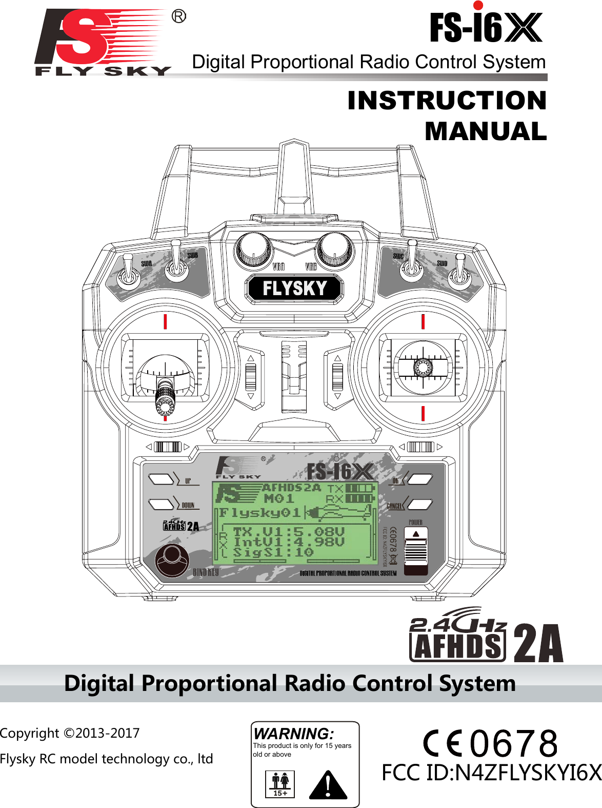
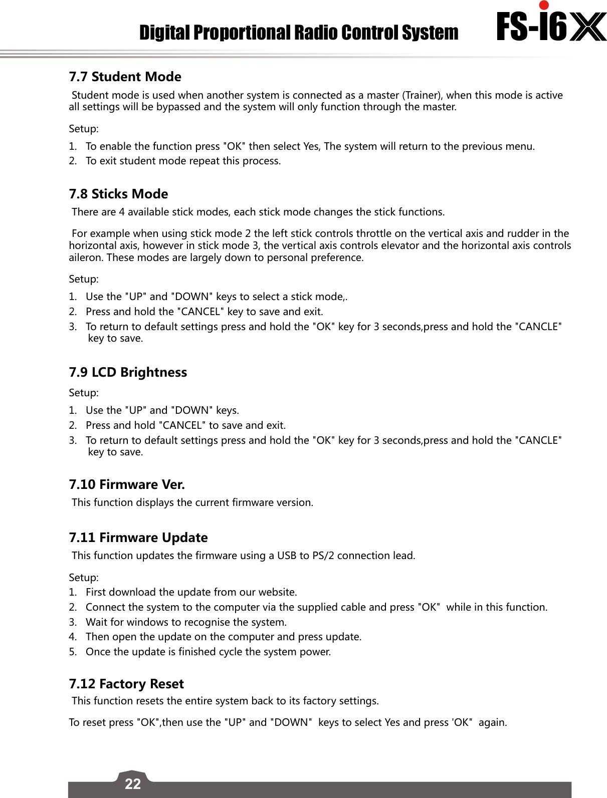
![25FS-l6 1. Use the "UP" and "DOWN" to choose a channel and press "OK" to enter its failsafe settings. 2. Use the "UP" and "DOWN" to turn the failsafe on or off. 3. Move the channels control surface to the desired position and hold the "CANCEL" key to confirm and exit.4. To return to default settings press and hold the "OK" key for 3 seconds,use the "UP" and "DOWN" keys to select Yes. press and hold the "CANCLE" key to save.You can set the failsafe position for all channels with the[All channels] button at once. To do so,1. Move all your channels to the desired position.2. Select [All channels].• Oncethefailsafehasbeenset,apercentagewillbedisplayed.8.5 Sensors ListThis function displays all connected sensors and thier outputs. 8.6 Choose SensorsThis function changes which sensors will be displayed on the home screen. The home screen can display up to 3 sensors. Setup:1. To add a sensor to the home screen, use the "OK" key to change sensor slot, then use the "UP" and "DWON" keys to select a sensor. 2. To return to default settings press and hold the "OK" key for 3 seconds, Press and hold the "CANCEL" key to save and exit. 8.7 Speed and Distance This function is for setting up speed and distance sensors. Speed SensorIf a sensors is connected, us the "UP" and "DOWN" arrow keys to select the desired senor then press and hold the "CANCEL" key to save. Rotation LengthMeasure the distance from the center of the prop to the distance sensor. Then use the "UP" and "DOWN" arrow keys to enter the length. Press and hold the "CANCEL" key to save. Reset Odometer 1 + 2These settings return the odometer to 0. To reset select one, odometer 1 or 2, then press "OK". The system will display a prompt, select yes. Reset odometer 1Resets odometer 1 to 0. Odometer 1 records the distance traveled during a session. Note that restarting the system will also reset odometer 1.Reset odometer 2Resets odometer 2 to 0. Odometer 2 records the total distance traveled since last reset. This means that the distance over several sessions will be added together.](https://usermanual.wiki/FLYSKY-RC-MODEL-TECHNOLOGY/FLYSKYI6X/User-Guide-3044503-Page-26.png)
![26Digital Proportional Radio Control System FS-l6 8.8 ASL PressureThe set ASL (Above Sea Level) function is used to calibrate an altitude sensor. When an altitude sensor is connected, change the [Air pressure] setting until the altitude is at 0m. Setup:1. Make sure that your TX and RX are bound and turned on.2. Set your model on the ground.3. Use the “UP”and “DOWN” keys to change the hPa value. If the system is showing a positive altitude, reduce the hPa value until the altitude reaches 0m. If the system is showing a negative altitude increase the hPa value until it reaches 0m.4. To return to default settings press and hold the "OK" key for 3 seconds,press and hold the "CANCLE" key to save.Note: Make sure that your model is at ground level during this process.8.9 i-BUS SetupThis function is used to set up the i-BUS module. The i-BUS module can be used to add servos to your model that may be too far away from the receiver.Setup:1. Use the "UP" and "DOWN" keys to choose a channel and press "OK". 2. Press the button on the i-bus module that corresponds to the desired output, the system will then return to the previous menu. 3. After setting up the desired channels press and hold the "CANCEL" key to save and exit.8.10 Servos FreqThis function sets the frequency that the receiver outputs to the servos. Check your servos usermanual to find the correct setting.](https://usermanual.wiki/FLYSKY-RC-MODEL-TECHNOLOGY/FLYSKYI6X/User-Guide-3044503-Page-27.png)