Flyingvoice Network Technology FTA1101 VoIP Wireless ATA User Manual user manual
Flyingvoice Network Technology Co., Ltd VoIP Wireless ATA user manual
UserManual.wiki
>
Flyingvoice Network Technology
>
FTA1101 User Manual
User manual
Navigation menu
Upload a User Manual
Namespaces
Wiki Guide
HTML
PDF
Info
Views
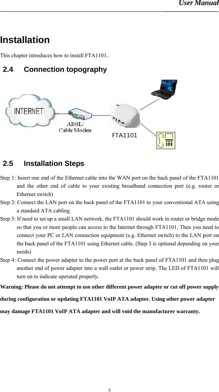
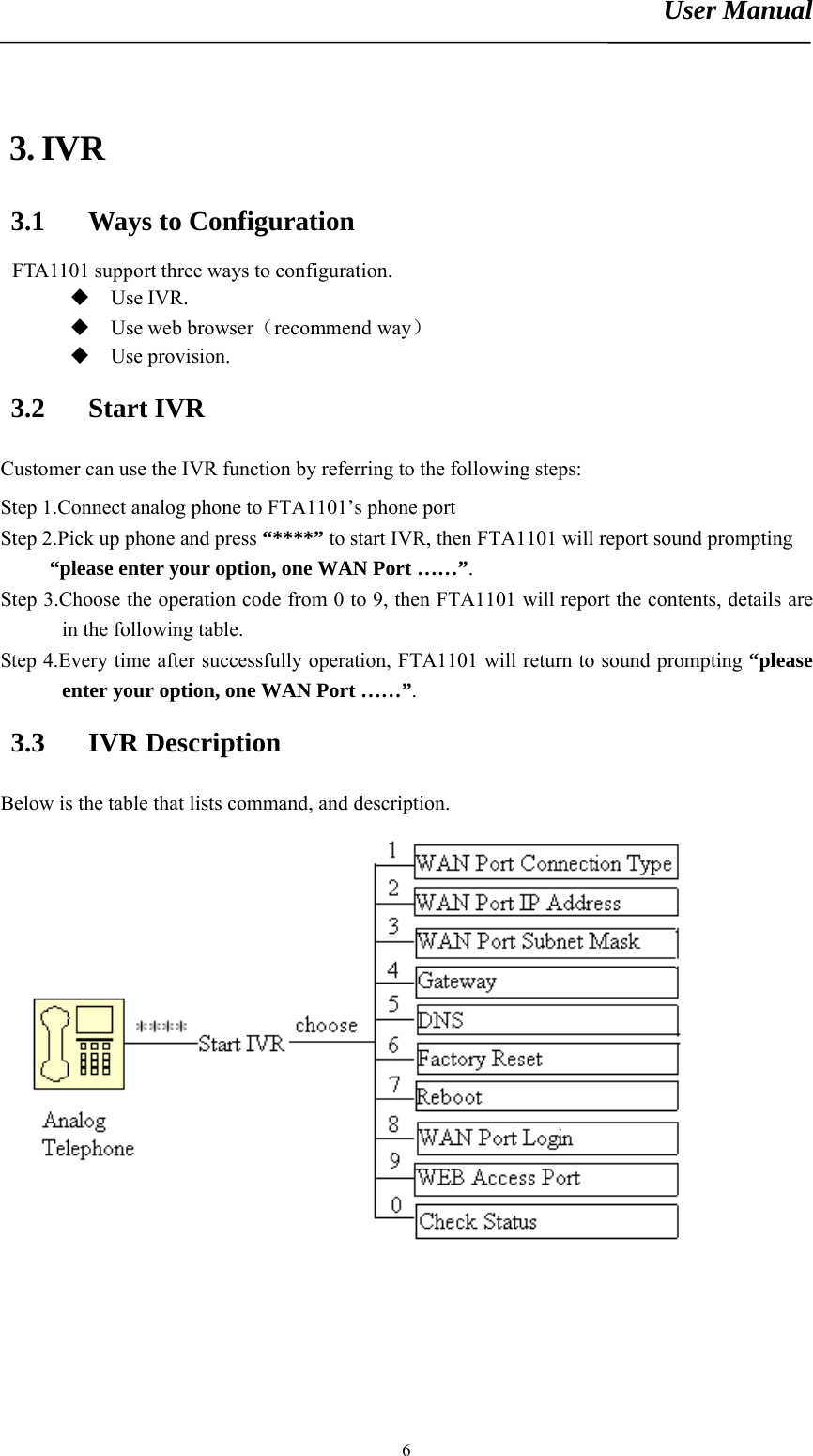
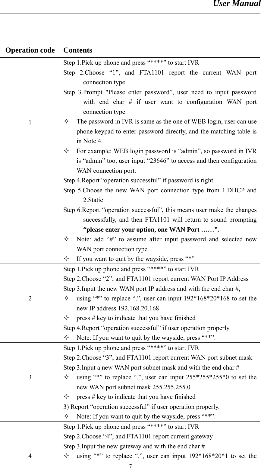
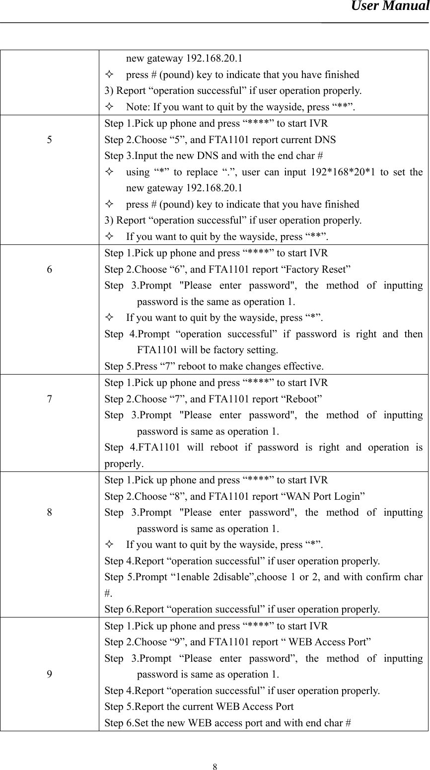
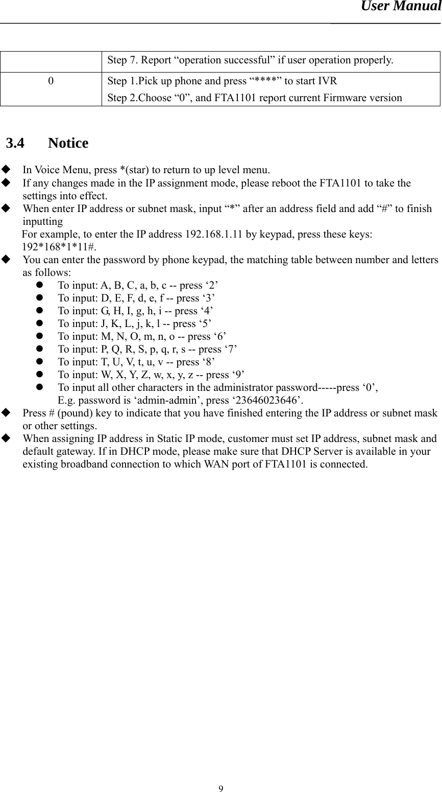
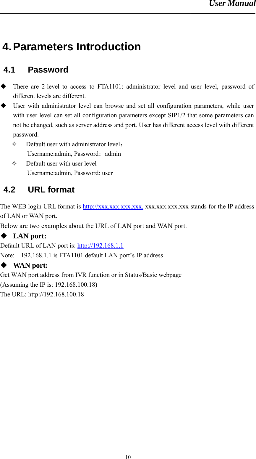
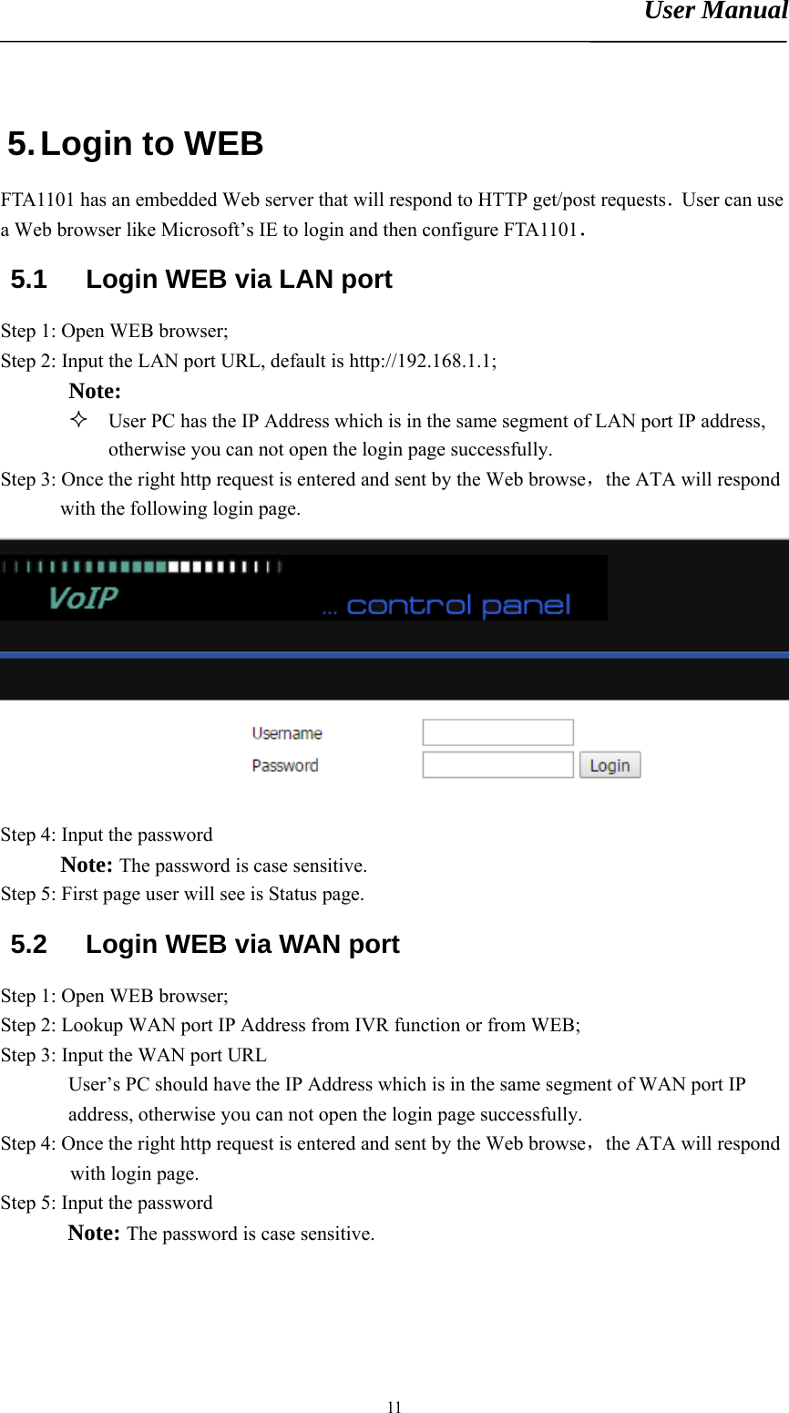
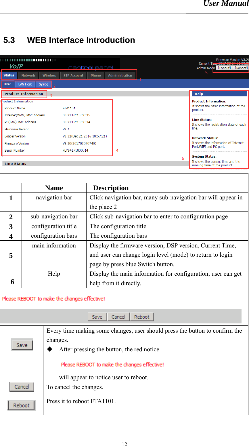
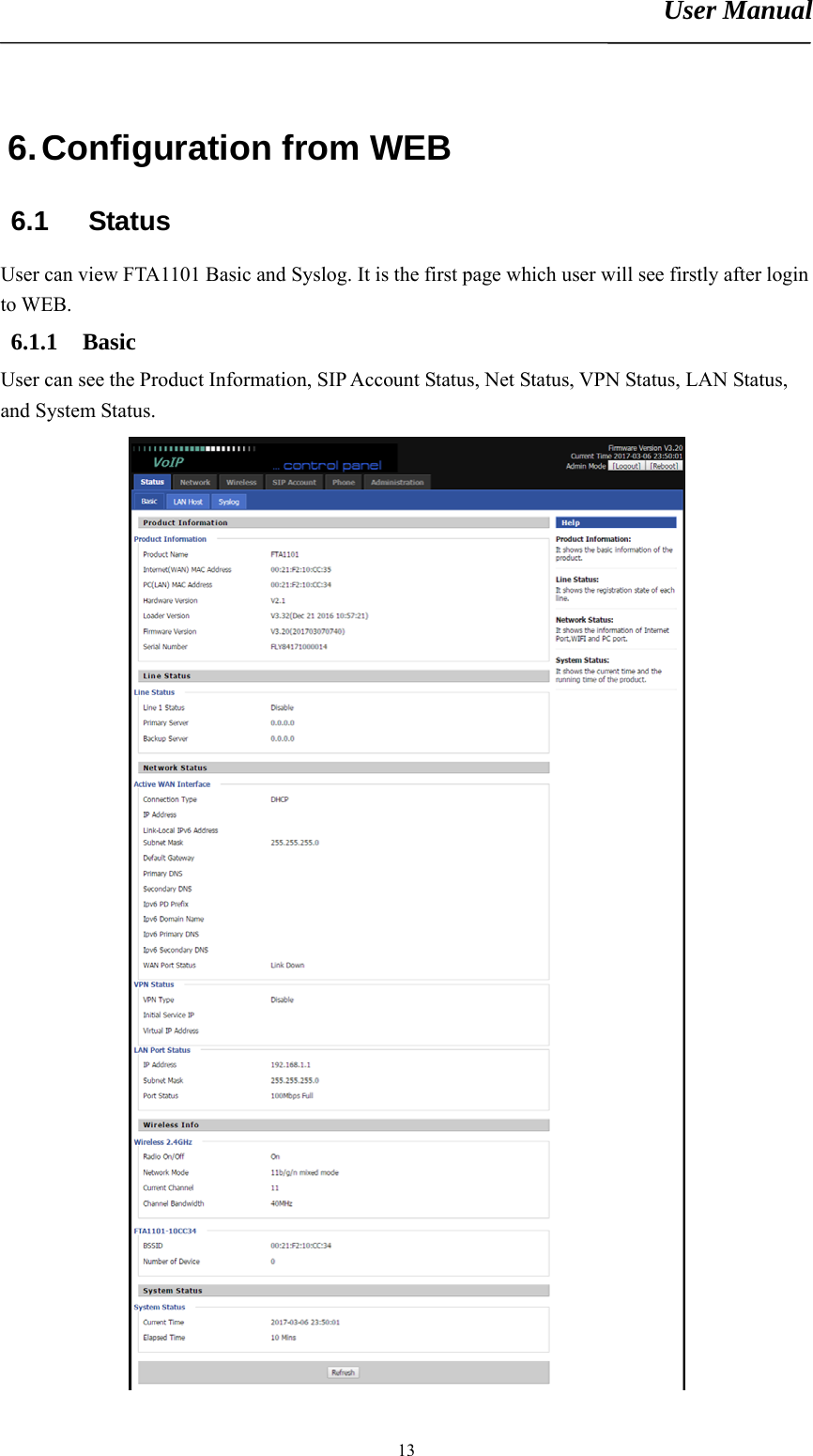
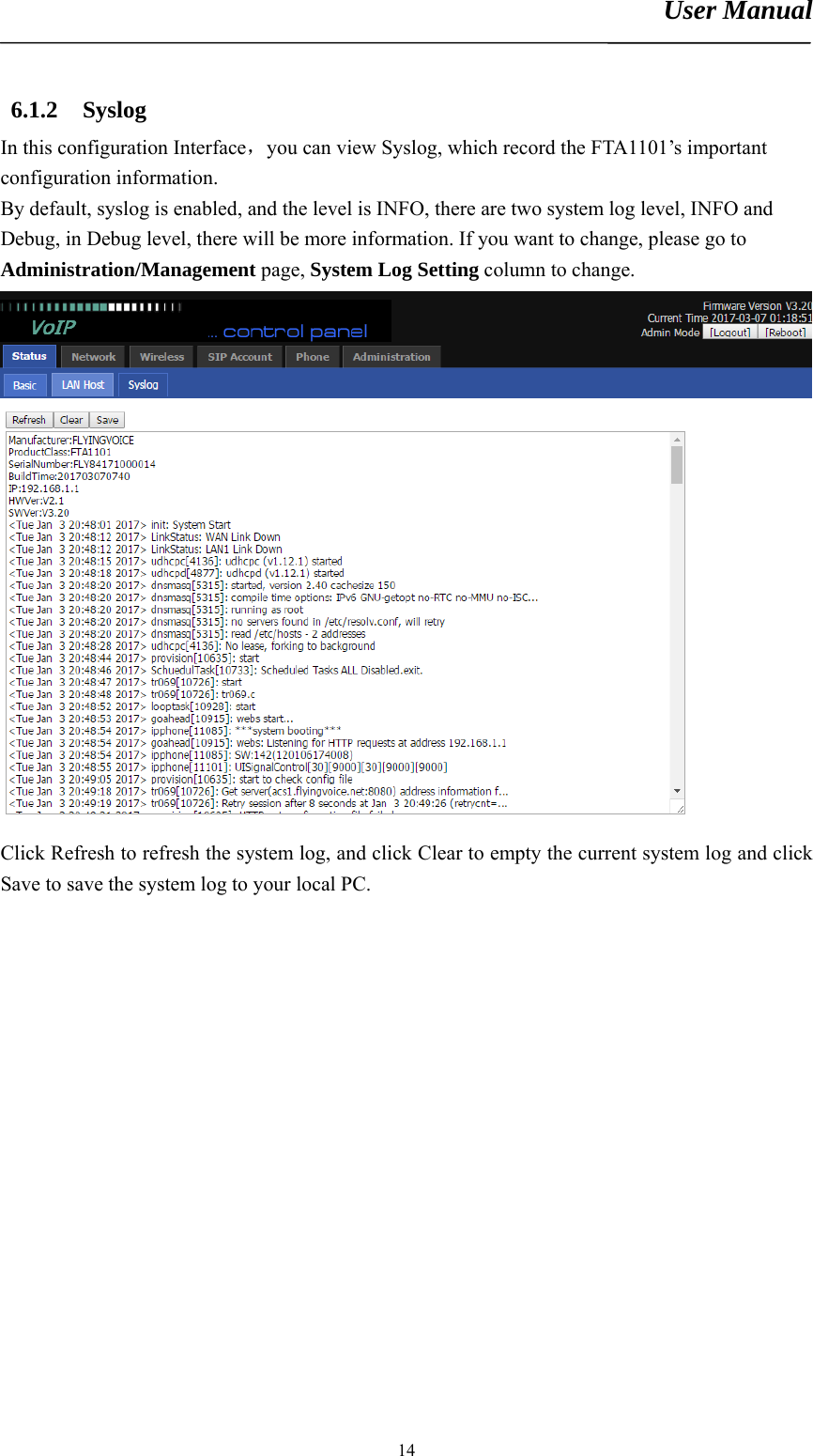
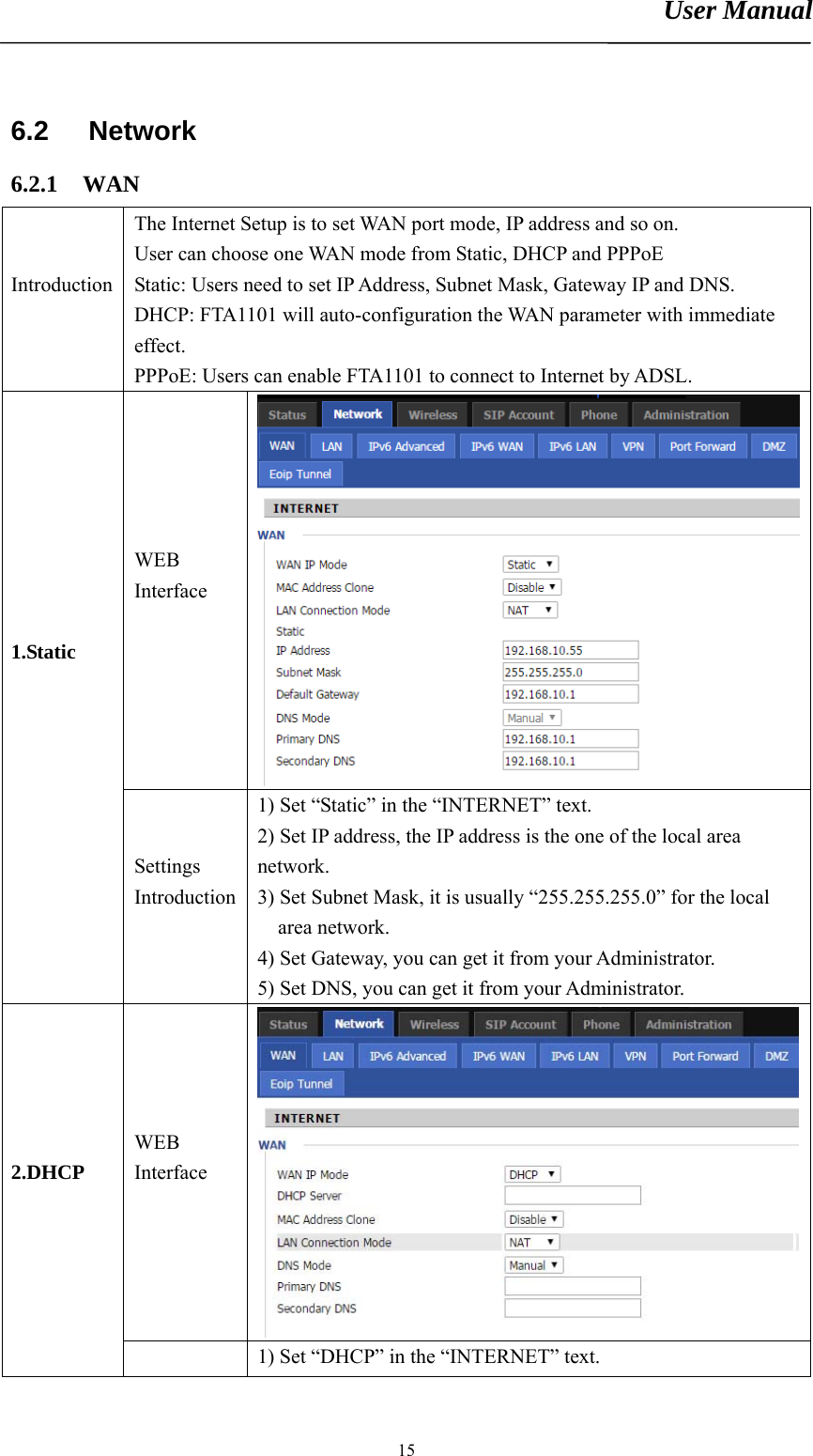
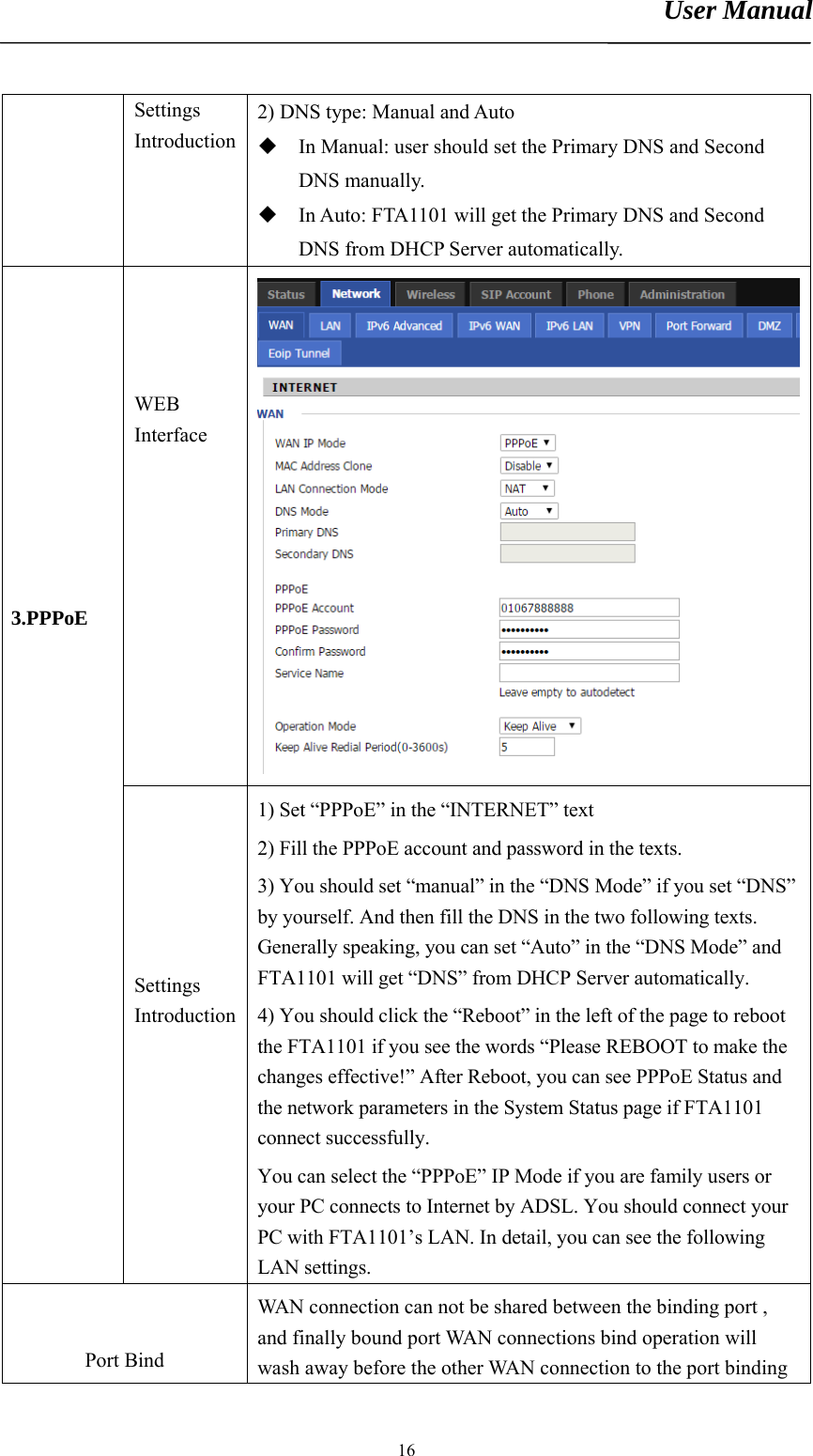
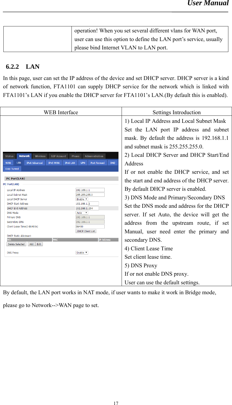
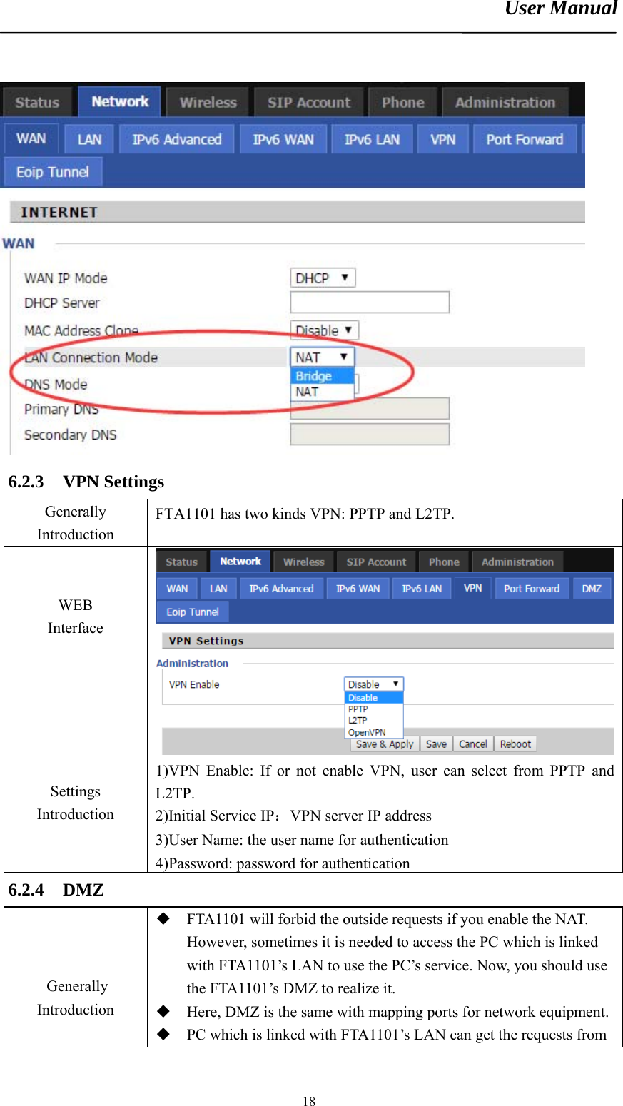
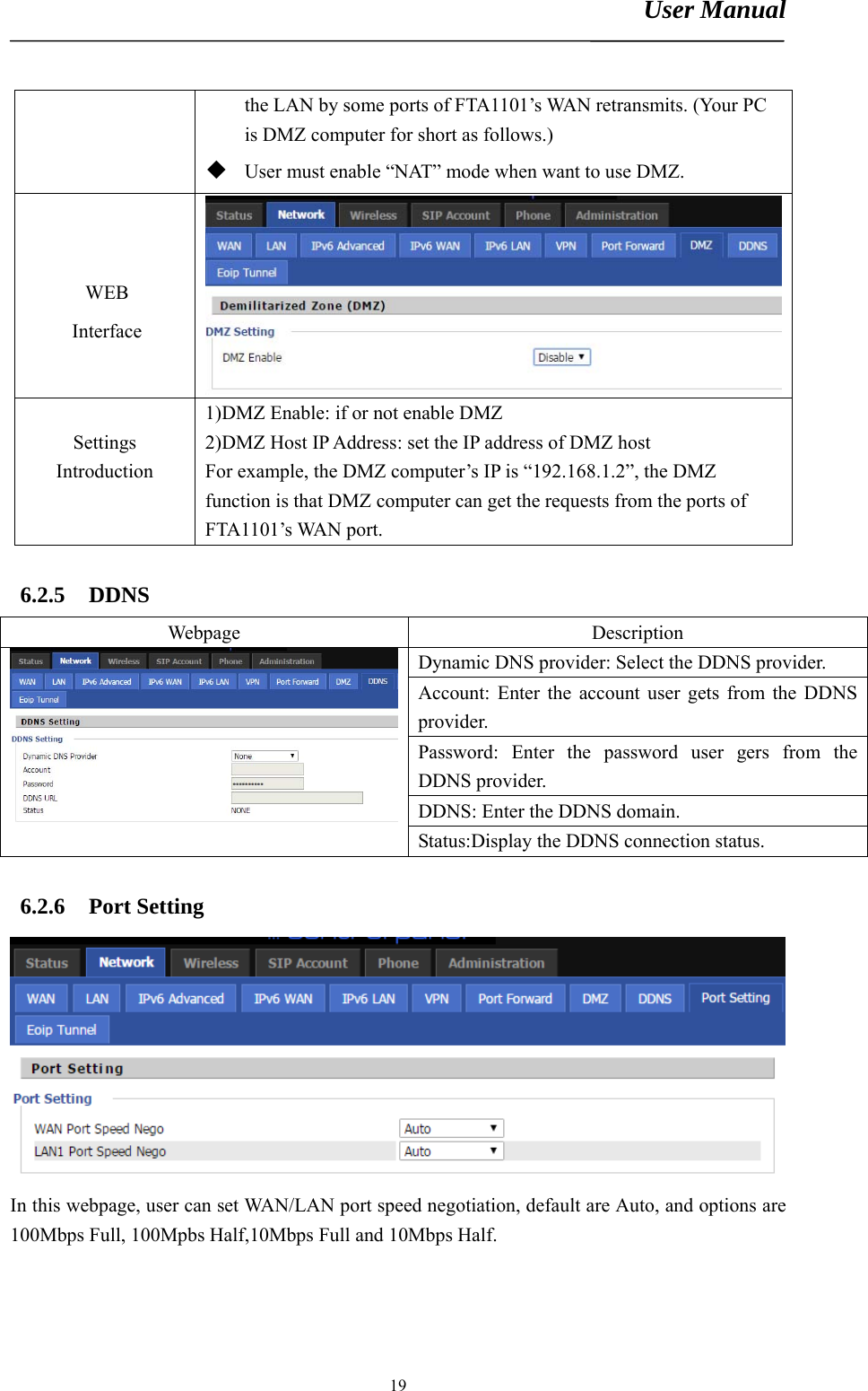
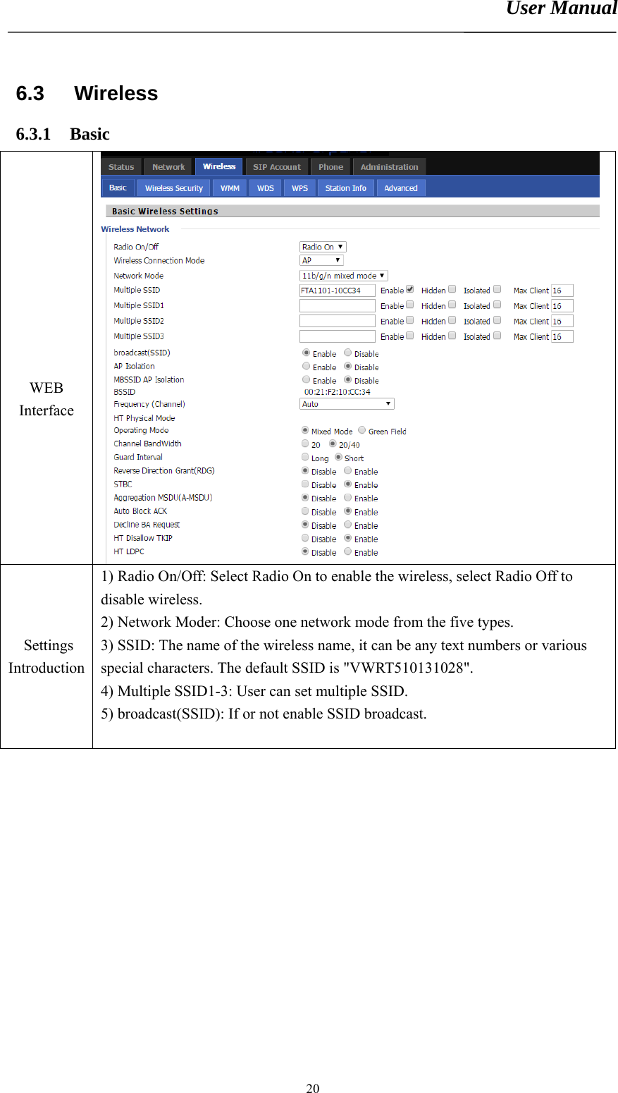
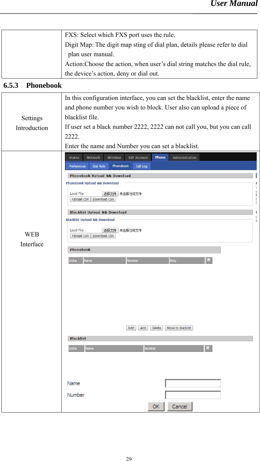
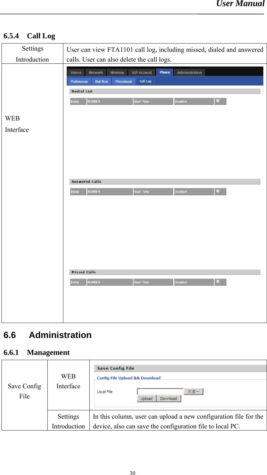
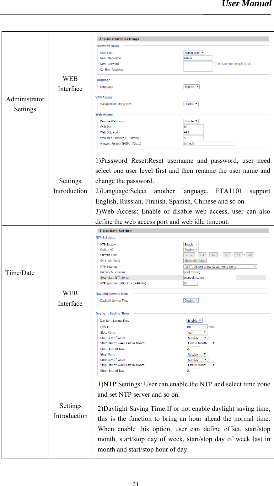
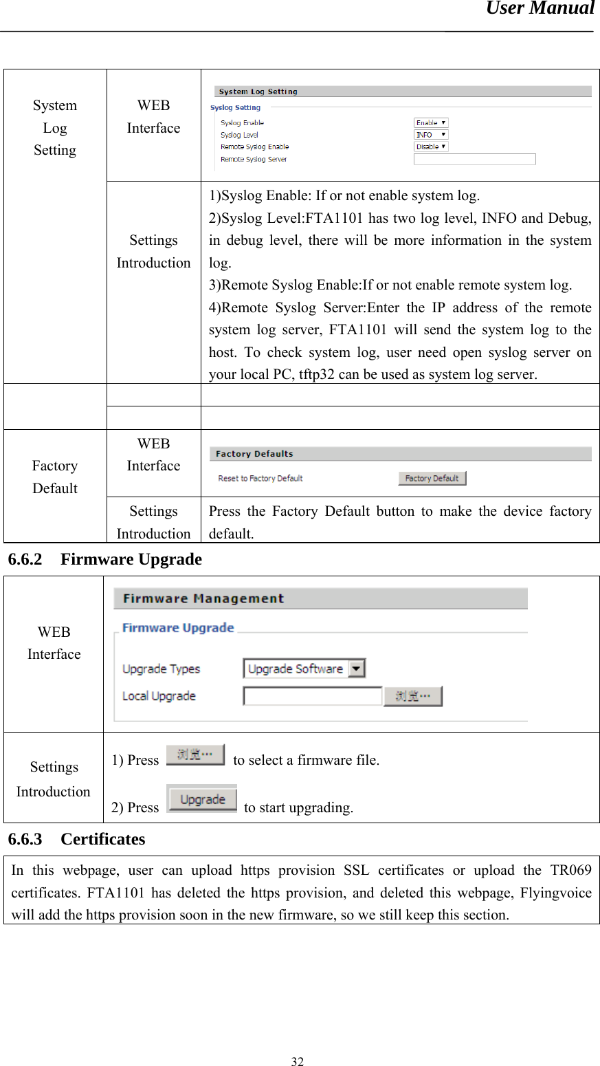
User Manual
Discussion / Help
Navigation