Fortress Auto EB937 The Multi-Angle Digital Wireless Parking Camera User Manual
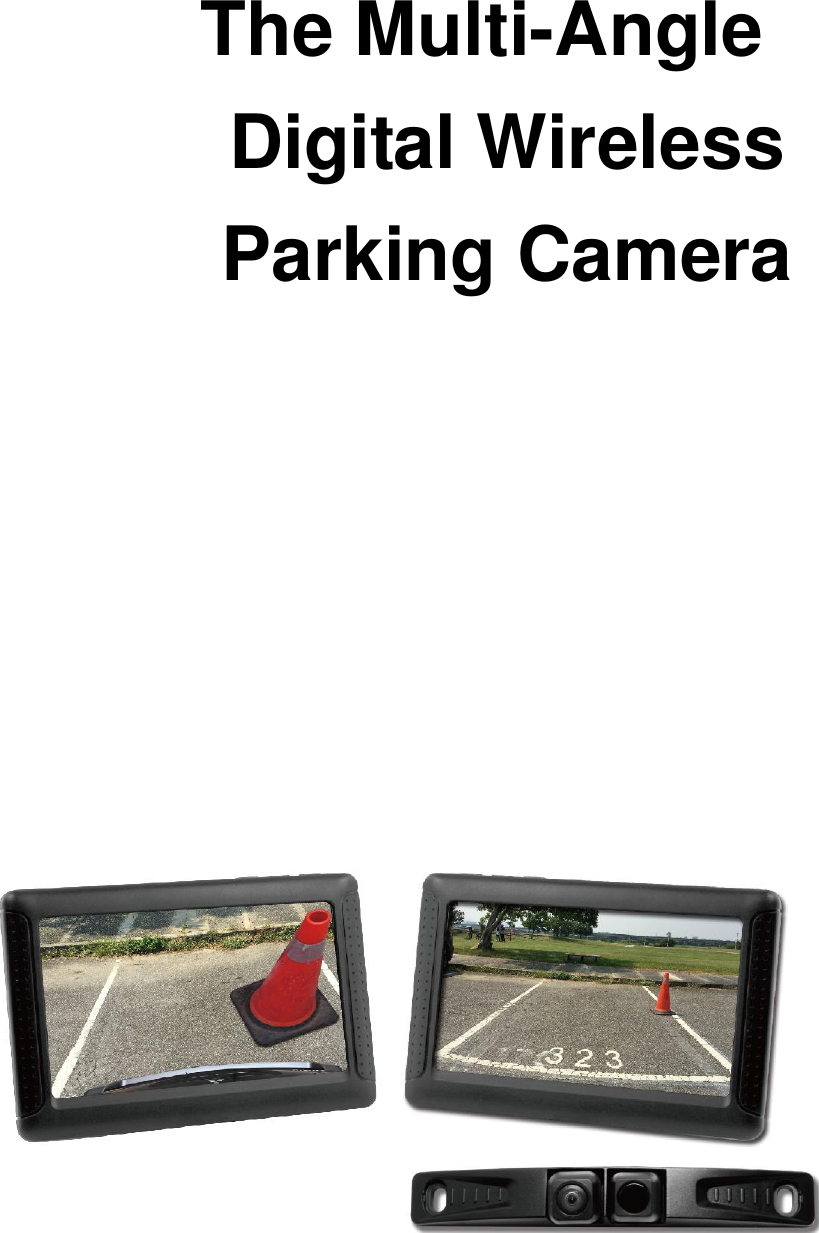
Fortress Auto Int'l Ltd The Multi-Angle Digital Wireless Parking Camera
UserManual.wiki
>
Fortress Auto
>
EB937 User Manual
User Manual
Navigation menu
Upload a User Manual
Namespaces
Wiki Guide
HTML
PDF
Info
Views
User Manual
Discussion / Help
Navigation
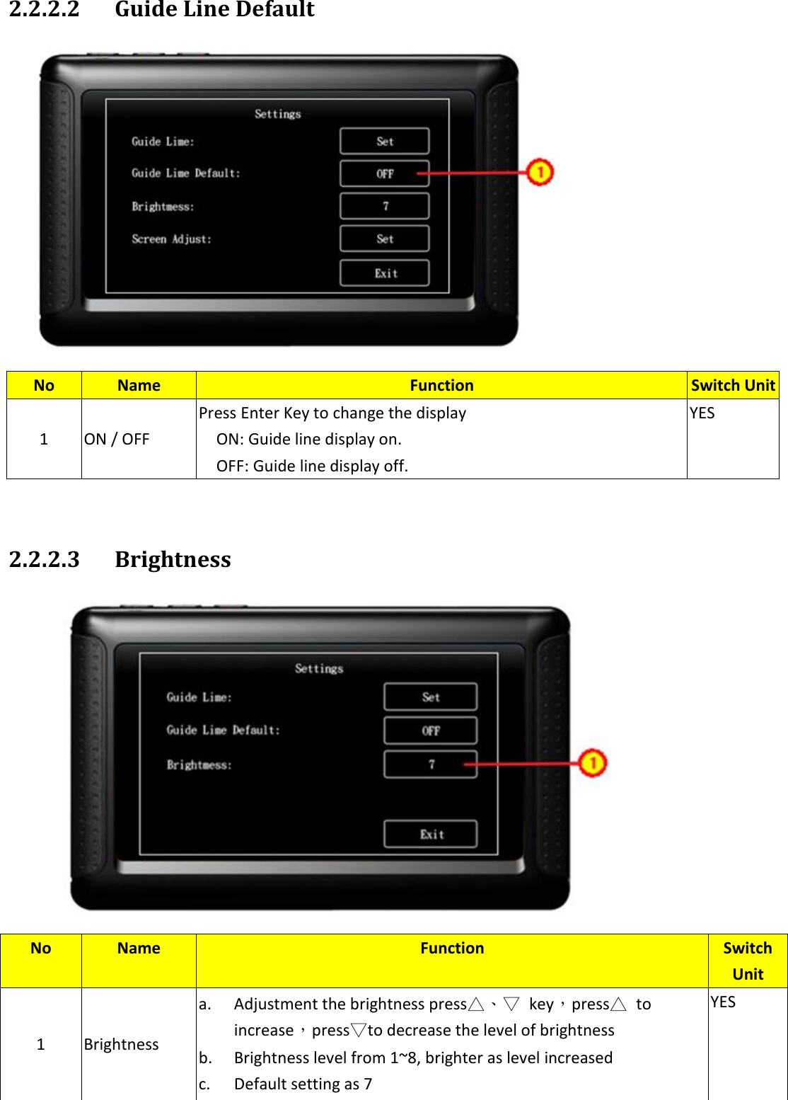
![2.2.2. Settings Note: This system use high brightness/yellow to mark the content. See above[Exit] Contents: 2.2.2.1 Guide Line 2.2.2.2 Guide Line Default 2.2.2.3 Brightness No Name Function Switch Unit 1 Settings Menu N/A 2 Setting item Setting title N/A 3 Setting item corresponding button a. Setting item corresponding button b. High brightness display when setted YES 4 Exit a. High brightness display when setted b. Back to Camera mode YES,Default](https://usermanual.wiki/Fortress-Auto/EB937/User-Guide-3171551-Page-5.png)
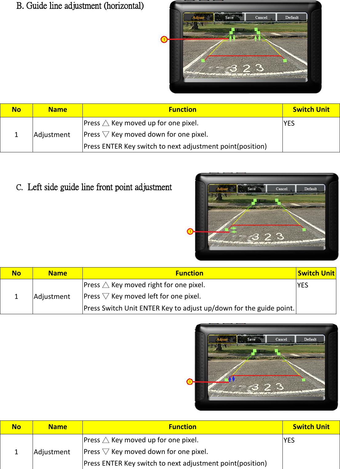
![Guide Line Guide line setting/display. Buttons function (1)Guide Line Setting A. Adjustment of the guiding line position. No Name Function Switch Unit 1 Adjust Press ENTER and adjust the guide line YES,Default 2 Save Press△、▽ Key to move the spot into position[Guide Line] [Save]、Press ENTER and saved, then exit setting. YES 3 Cancel Press△、▽ Key to move the spot into position[Guide Line] [Cancel]、 Press ENTER and not Saved, then exit setting YES 4 Default Press△、▽ Key to move the spot into position[Guide Line] [Default]、Press ENTER, then back to default setting. YES No Name Function Switch Unit 1 Adjustment Press △ Key moved up for one pixel. Press ▽ Key moved down for one pixel. Press ENTER Key switch to next adjustment point(position) YES](https://usermanual.wiki/Fortress-Auto/EB937/User-Guide-3171551-Page-6.png)