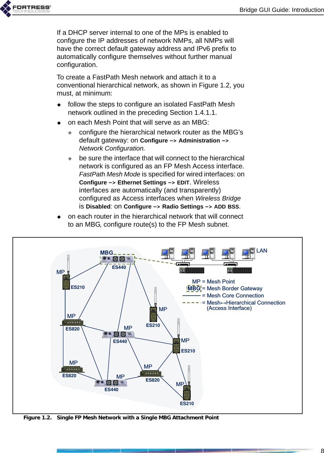
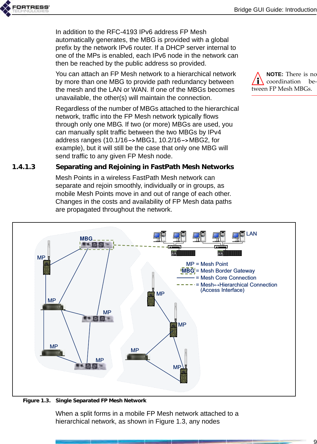
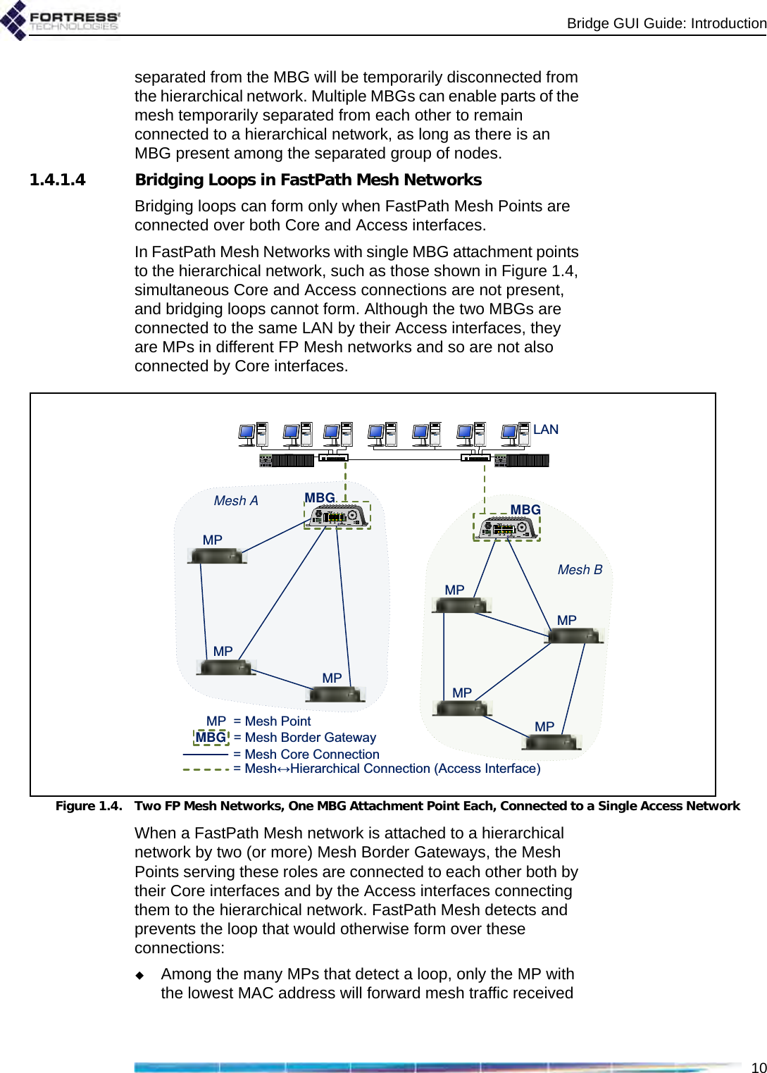
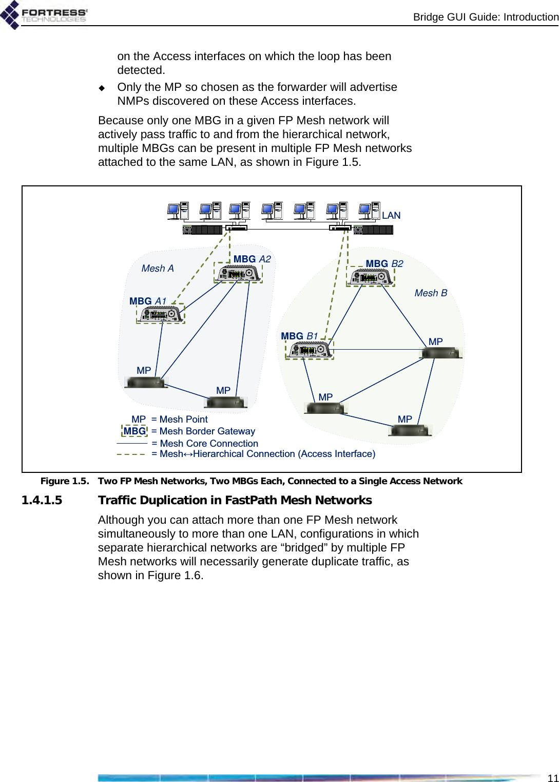
Fortress Technologies ES820 The ES820 is a dual radio access point/bridge. It provides secure connectivity through multiple Ethernet ports and two 802.11 a/b/g radios in a ruggedized enclosure. It provides secure, fixed or mobile communications for harsh environments. User Manual GUI Guide
Fortress Technologies, Inc. The ES820 is a dual radio access point/bridge. It provides secure connectivity through multiple Ethernet ports and two 802.11 a/b/g radios in a ruggedized enclosure. It provides secure, fixed or mobile communications for harsh environments. GUI Guide
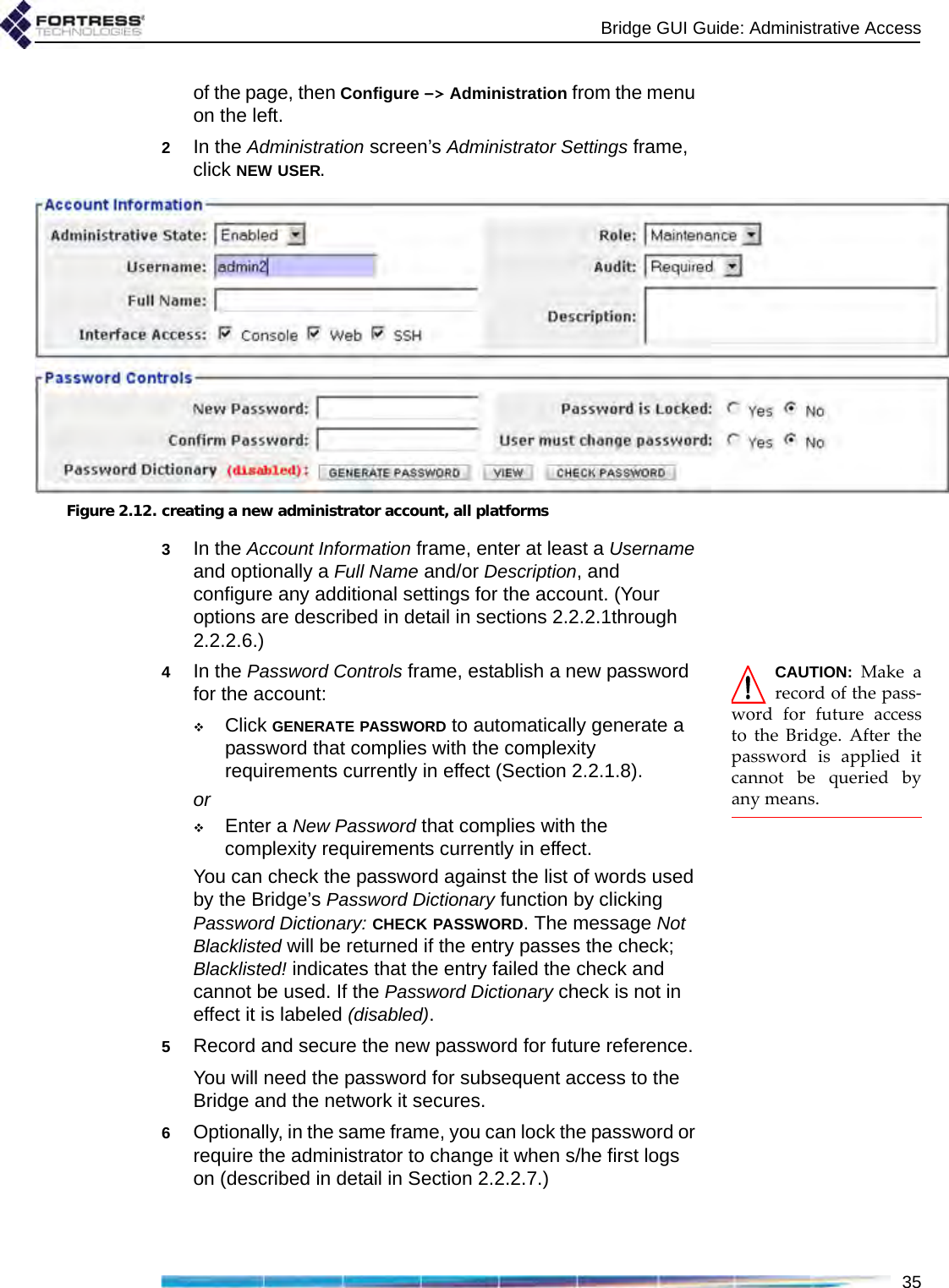
GUI Guide
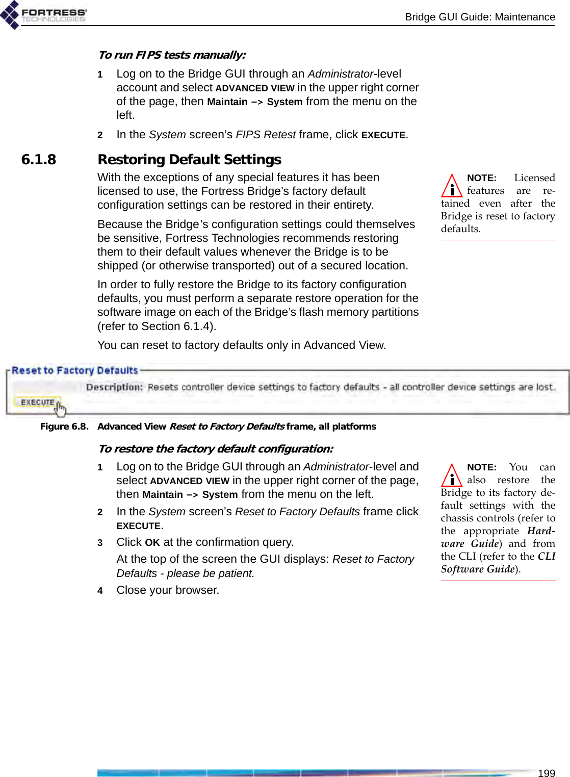
![Bridge GUI Guidei009-00035-00v5.4r1Fortress Bridge and Controller version 5.4 Software GUI Guide [rev.1]Copyright © 2010 Fortress Technologies, Inc. All rights reserved.This document contains proprietary information protected by copyright. No part of this document may be reproduced or transmitted in any form or by any means, electronic or mechanical, without written permission of Fortress Technologies, 4023 Tampa Road, Suite 2200, Oldsmar, FL 34677, except as specified in the Product Warranty and License Terms.FORTRESS TECHNOLOGIES, INC., MAKES NO WARRANTY OF ANY KIND WITH REGARD TO THIS MATERIAL, INCLUDING BUT NOT LIMITED TO THE IMPLIED WARRANTIES OF MERCHANTABILITY AND FITNESS FOR A PARTICULAR PURPOSE. FORTRESS TECHNOLOGIES, INC. SHALL NOT BE LIABLE FOR ERRORS CONTAINED HEREIN OR FOR INCIDENTAL OR CONSEQUENTIAL DAMAGES IN CONNECTION WITH THE FURNISHING, PERFORMANCE OR USE OF THIS MATERIAL. THE INFORMATION IN THIS DOCUMENT IS SUBJECT TO CHANGE WITHOUT NOTICE.The Fortress Technologies and AirFortress logos and AirFortress and are registered trademarks; Multi-Factor Authentication, Unified Security Model, Wireless Link Layer Security and Three Factor Authentication (TFA) are trademarks of Fortress Technologies, Inc. The technology behind Wireless Link Layer Security™ enjoys U.S. and international patent protection under patent number 5,757,924.Portions of this software are covered by the GNU General Public License (GPL) Copyright © 1989, 1991 Free Software Foundation, Inc,. 59 Temple Place, Suite 330, Boston, MA 02111-1307 USA. To receive a complete machine-readable copy of the corresponding source code on CD, send $10 (to cover the costs of production and mailing) to: Fortress Technologies; 4023 Tampa Road, suite 2200; Oldsmar, FL 34677-3216. Please be sure to include a copy of your Fortress Technologies invoice and a valid “ship to” address.This product includes cryptographic software written by Eric Young (eay@cryptsoft.com). This product includes software written by Tim Hudson (tjh@cryptsoft.com).Copyright © 1995-1998 Eric Young (eay@cryptsoft.com) All rights reserved.This package is an SSL implementation written by Eric Young (eay@cryptsoft.com). The implementation was written so as to conform with Netscape’s SSL.THIS SOFTWARE IS PROVIDED BY ERIC YOUNG ``AS IS'' AND ANY EXPRESS OR IMPLIED WARRANTIES, INCLUDING, BUT NOT LIMITED TO, THE IMPLIED WARRANTIES OF MERCHANTABILITY AND FITNESS FOR A PARTICULAR PURPOSE ARE DISCLAIMED. IN NO EVENT SHALL THE AUTHOR OR CONTRIBUTORS BE LIABLE FOR ANY DIRECT, INDIRECT, INCIDENTAL, SPECIAL, EXEMPLARY, OR CONSEQUENTIAL DAMAGES (INCLUDING, BUT NOT LIMITED TO, PROCUREMENT OF SUBSTITUTE GOODS OR SERVICES; LOSS OF USE, DATA, OR PROFITS; OR BUSINESS INTERRUPTION) HOWEVER CAUSED AND ON ANY THEORY OF LIABILITY, WHETHER IN CONTRACT, STRICT LIABILITY, OR TORT (INCLUDING NEGLIGENCE OR OTHERWISE) ARISING IN ANY WAY OUT OF THE USE OF THIS SOFTWARE, EVEN IF ADVISED OF THE POSSIBILITY OF SUCH DAMAGE. Atheros, the Atheros logo, Atheros Driven, Driving the wireless future, Super G and Super AG are all registered trademarks of Atheros Communications. ROCm, JumpStart for Wireless, Atheros XR, Wake-on-Wireless, Wake-on-Theft, and FastFrames, are all trademarks of Atheros Communications, Inc. This product uses Dynamic Host Control Protocol, Copyright © 2004–2010 by Internet Software Consortium, Inc. Copyright © 1995–2003 by Internet Software Consortium. All rights reserved.This product includes software developed by the OpenSSL Project for use in the OpenSSL Toolkit. (http://www.openssl.org/)Copyright © 1998-2007 The OpenSSL Project. All rights reserved.THIS SOFTWARE IS PROVIDED BY THE OpenSSL PROJECT ``AS IS'' AND ANY EXPRESSED OR IMPLIED WARRANTIES, INCLUDING, BUT NOT LIMITED TO, THE IMPLIED WARRANTIES OF MERCHANTABILITY AND FITNESS FOR A PARTICULAR PURPOSE ARE DISCLAIMED. IN NO EVENT SHALL THE OpenSSL PROJECT OR ITS CONTRIBUTORS](https://usermanual.wiki/Fortress-Technologies/ES820.GUI-Guide/User-Guide-1413931-Page-2.png)
![Bridge GUI GuidevFortress]. Date of shipment is established per the shipping document (packing list) for the Product that is shipped from Fortress location. Customer shall provide Fortress with access to the Product to enable Fortress to diagnose and correct any errors or defects. If the Product is found defective by Fortress, Fortress' sole obligation under this warranty is to remedy such defect at Fortress' option through repair, upgrade or replacement of product. Services and support provided to diagnose a reported issue with a Fortress Product, which is then determined not to be the root cause of the issue, may at Fortress’ option be billed at the standard time and material rates. Warranty ExclusionsThe warranty does not cover Fortress Hardware Product or Software or any other equipment upon which the Software is authorized by Fortress or its suppliers or licensors, which (a) has been damaged through abuse or negligence or by accident, (b) has been altered except by an authorized Fortress representative, (c) has been subjected to abnormal physical or electrical stress (i.e., lightning strike) or abnormal environmental conditions, (d) has been lost or damaged in transit, or (e) has not been installed, operated, repaired or maintained in accordance with instructions provided by Fortress.The warranty is voided by removing any tamper evidence security sticker or marking except as performed by a Fortress authorized service technician.Fortress does not warrant uninterrupted or error-free operation of any Products or third party software, including public domain software which may have been incorporated into the Fortress Product. Fortress will bear no responsibility with respect to any defect or deficiency resulting from accidents, misuse, neglect, modifications, or deficiencies in power or operating environment.Unless specified otherwise, Fortress does not warrant or support non-Fortress products. If any service or support is rendered such support is provided WITHOUT WARRANTIES OF ANY KIND. DISCLAIMER OF WARRANTYTHE WARRANTIES HEREIN ARE SOLE AND EXCLUSIVE, AND NO OTHER WARRANTY, WHETHER WRITTEN OR ORAL, IS EXPRESSED OR IMPLIED. TO THE EXTENT PERMITTED BY LAW, FORTRESS SPECIFICALLY DISCLAIMS THE IMPLIED WARRANTIES OF MERCHANTABILITY, FITNESS FOR A PARTICULAR PURPOSE, TITLE AND NONINFRINGEMENT.General Terms Applicable to the Limited Warranty and End User License AgreementDisclaimer of LiabilitiesTHE FOREGOING WARRANTIES ARE THE EXCLUSIVE WARRANTIES AND REPLACE ALL OTHER WARRANTIES OR CONDITIONS, EXPRESS OR IMPLIED, INCLUDING, BUT NOT LIMITED TO, THE IMPLIED WARRANTIES OR CONDITIONS OF MERCHANTABILITY AND FITNESS FOR A PARTICULAR PURPOSE. FORTRESS SHALL HAVE NO LIABILITY FOR CONSEQUENTIAL, EXEMPLARY, OR INCIDENTAL DAMAGES EVEN IF IT HAS BEEN ADVISED OF THE POSSIBILITY OF SUCH DAMAGES. THE STATED LIMITED WARRANTY IS IN LIEU OF ALL LIABILITIES OR OBLIGATIONS OF FORTRESS FOR DAMAGES ARISING OUT OF OR IN CONNECTION WITH THE DELIVERY, USE, OR PERFORMANCE OF THE PRODUCTS (HARDWARE AND SOFTWARE). THESE WARRANTIES GIVE SPECIFIC LEGAL RIGHTS AND CUSTOMER MAY ALSO HAVE OTHER RIGHTS WHICH VARY FROM JURISDICTION TO JURISDICTION. SOME JURISDICTIONS DO NOT ALLOW THE EXCLUSION OR LIMITATION OF EXPRESS OR IMPLIED WARRANTIES, SO THE ABOVE EXCLUSION OR LIMITATION MAY NOT APPLY TO YOU. IN THAT EVENT, SUCH WARRANTIES ARE LIMITED IN DURATION TO THE WARRANTY PERIOD. NO WARRANTIES APPLY AFTER THAT PERIOD.Product Warranty and License Terms IndemnificationFortress will defend any action brought against Customer based on a claim that any Fortress Product infringes any U.S. patents or copyrights excluding third party software, provided that Fortress is immediately notified in writing and Fortress has the right to control](https://usermanual.wiki/Fortress-Technologies/ES820.GUI-Guide/User-Guide-1413931-Page-6.png)
![Bridge GUI Guidevithe defense of all such claims, lawsuits, and other proceedings. If, as a result of any claim of infringement against any U.S. patent or copyright, Fortress is enjoined from using the Product, or if Fortress believes the Product is likely to become the subject of a claim of infringement, Fortress at its option and expense may procure the right for Customer to continue to use the Product, or replace or modify the Product so as to make it non-infringing. If neither of these two options is reasonably practicable, Fortress may discontinue the license granted herein on one month's written notice and refund to Licensee the unamortized portion of the license fees hereunder. The depreciation shall be an equal amount per year over the life of the Product as established by Fortress. The foregoing states the entire liability of Fortress and the sole and exclusive remedy of the Customer with respect to infringement of third party intellectual property.Limitation of Liability Circumstances may arise where, because of a default on Fortress' part or other liability, Customer is entitled to recover damages from Fortress. In each such instance, regardless of the basis on which you are entitled to claim damages from Fortress (including fundamental breach, negligence, misrepresentation, or other contract or tort claim), Fortress is liable for no more than damages for bodily injury (including death) and damage to real property and tangible personal property, and the amount of any other actual direct damages, up to either U.S. $25,000 (or equivalent in local currency) or the charges (if recurring, 12 months' charges apply) for the Product that is the subject of the claim, whichever is less. This limit also applies to Fortress' Solution Providers. It is the maximum for which Fortress and its Solution Providers are collectively responsible. UNDER NO CIRCUMSTANCES IS FORTRESS LIABLE FOR ANY OF THE FOLLOWING:1) THIRD-PARTY CLAIMS AGAINST YOU FOR DAMAGES,2) LOSS OF, OR DAMAGE TO, YOUR RECORDS OR DATA, OR3) SPECIAL, INCIDENTAL, OR INDIRECT DAMAGES OR FOR ANY ECONOMIC CONSEQUENTIAL DAMAGES (INCLUDING LOST PROFITS OR SAVINGS), EVEN IF FORTRESS OR ITS SOLUTION PROVIDER IS INFORMED OF THEIR POSSIBILITY. SOME JURISDICTIONS DO NOT ALLOW THE EXCLUSION OR LIMITATION OF INCIDENTAL OR CONSEQUENTIAL DAMAGES, SO THE ABOVE LIMITATION OR EXCLUSION MAY NOT APPLY TO CUSTOMER. Telephone SupportDuring the warranty period, Fortress or its Solution Provider will provide a reasonable amount of telephone consultation to the Customer. This support shall include assistance in connection with the installation and routine operation of the Product, but does not include network troubleshooting, security consultation, design and other services outside of the scope of routine Product operation. Warranty services for the Products shall be available during Fortress' normal U.S. (EST) business days and hours.Extended Warranty ServiceIf the Customer purchases an extended warranty service agreement with Fortress, service will be provided in accordance to said agreement's terms and conditions.Access and ServiceCustomer must provide Fortress or Solution Provider with access to the Product to enable Fortress or Solution Provider to provide the service. Access may include access via the Internet, on-site access or Customer shall be responsible for returning the Product to Fortress or Solution Provider. Fortress or Solution Provider will notify the Customer to obtain authorization to perform any repairs. If, during the warranty period, as established by the date of shipment [and in the case of resale by a Fortress Solution Provider, commencing not more than (90) days after original shipment by Fortress], the Customer finds any significant defect in materials and workmanship under normal use and operating conditions, the Customer shall notify Fortress Customer Service in accordance with the Fortress Service Policies in effect at that time which can be located on the Fortress web site: www.fortresstech.com.EULA Addendum for Products Containing 4.4 GHz Military Band Radio(s)This product contains one or more radios which operate in the 4.400GHz - 4.750GHz range.](https://usermanual.wiki/Fortress-Technologies/ES820.GUI-Guide/User-Guide-1413931-Page-7.png)
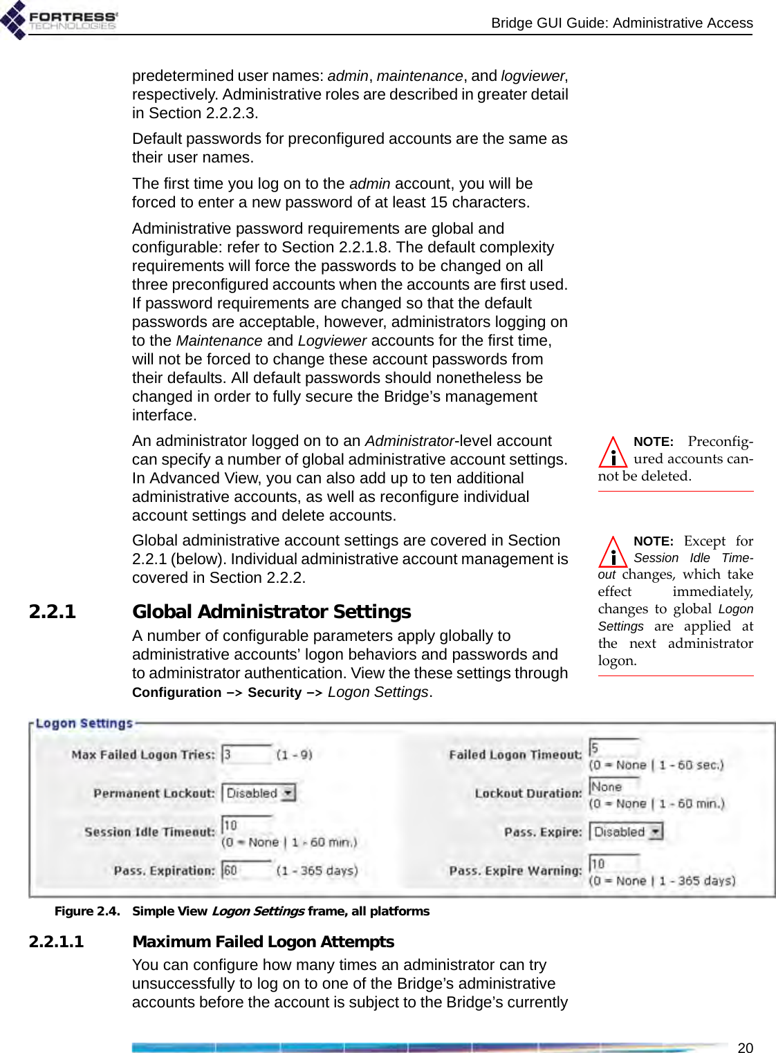
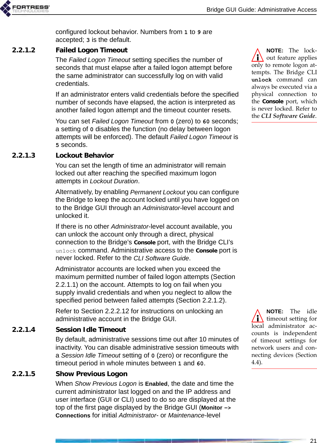
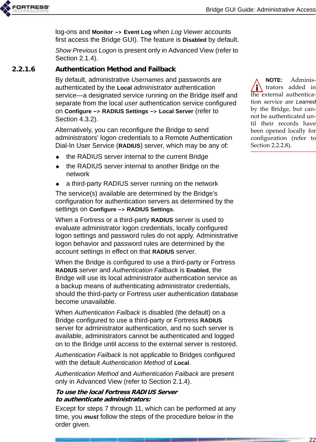
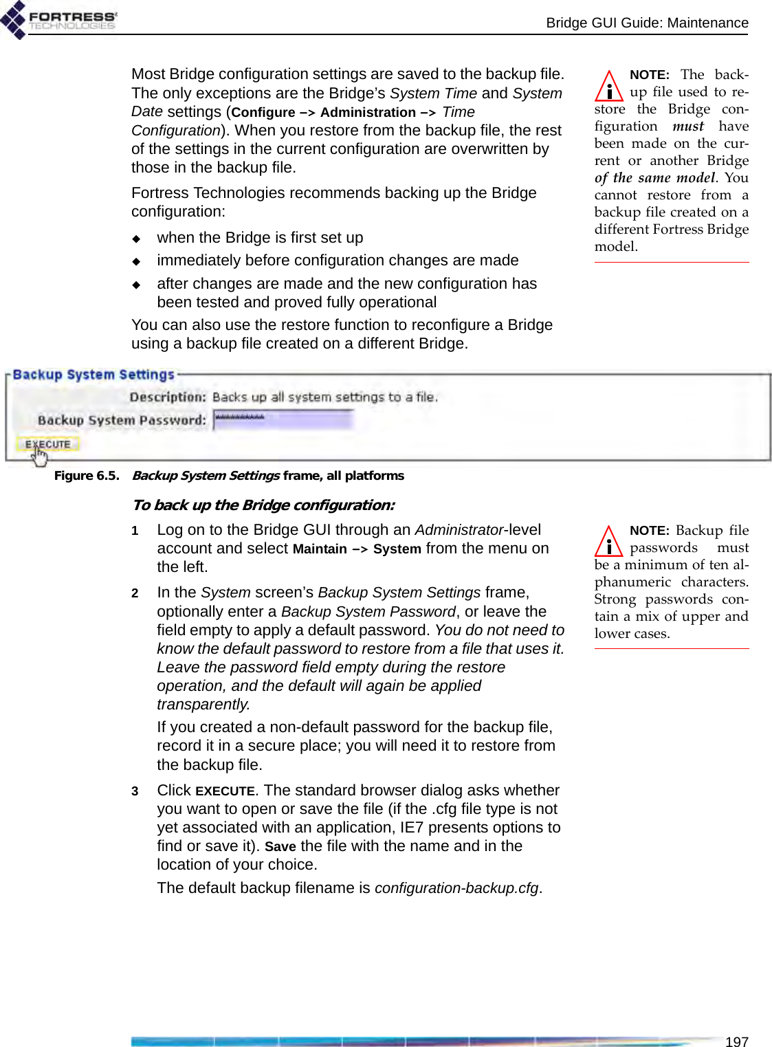
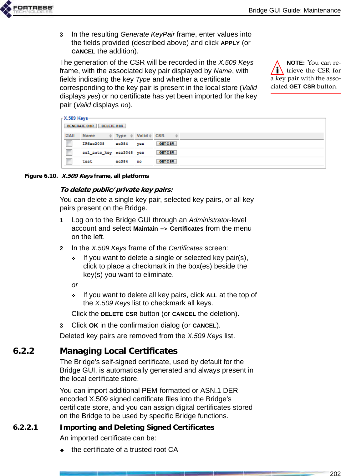
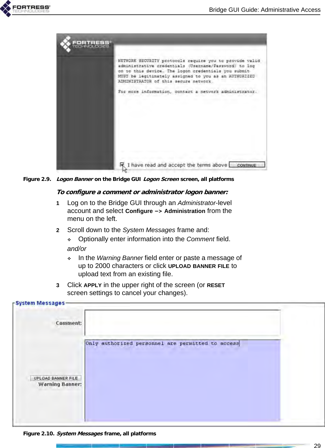
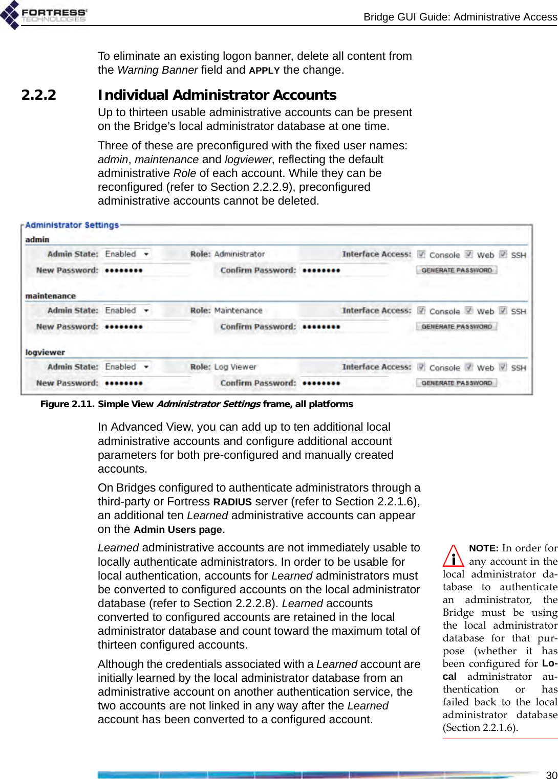
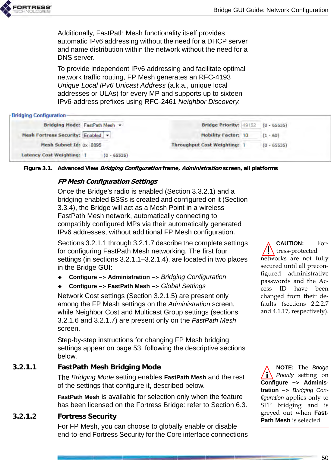
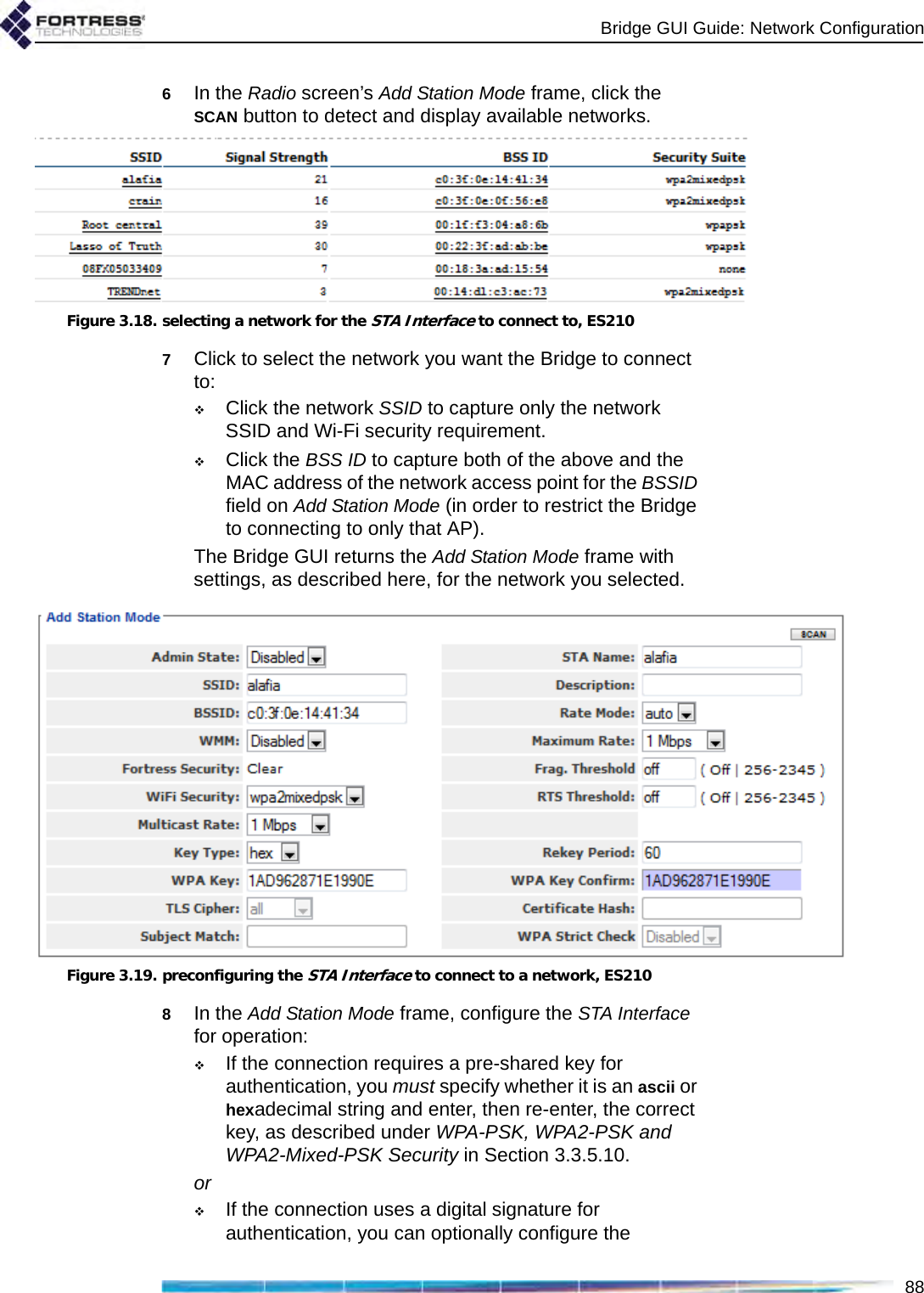
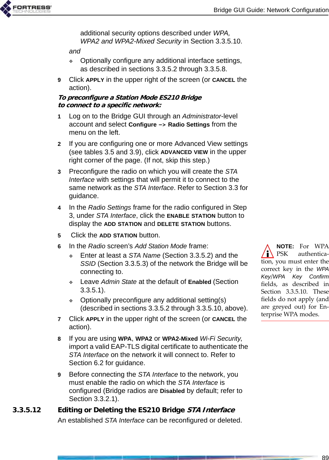
![Bridge GUI Guide: Administrative Access262.2.1.8 Password RequirementsNOTE: Passwordsdo not need to beunique.The Bridge will not accept new passwords that do not meet specified requirements. If you specify new requirements that existing passwords do not meet, nonconforming passwords are treated according to the Expire Nonconforming Passwords setting (described in Section 2.2.1.7).Configured complexity requirements apply equally to administrative passwords and to those of locally authenticated network users (Section 4.3.3.1).You can apply up to nine rules for administrative and local user passwords:Pass. Minimum Length - Passwords must be at least the specified number of characters long. You can specify values from 8 to 32 characters. The default is 15.Pass. Minimum Capitals - Passwords must contain at least the specified number of uppercase letters. You can specify values from 0 (zero) to 5; a 0 value (the default) allows passwords containing no uppercase letters.Pass. Minimum Lowercase - Passwords must contain at least the specified number of lowercase letters. You can specify values from 0 (zero) to 5; a 0 value (the default) allows passwords containing no lowercase letters.Pass. Minimum Numbers - Passwords must contain at least the specified number of numerals. You can specify values from 0 (zero) to 5; a 0 value (the default) allows passwords containing no numerals.Pass. Minimum Punctuation - Passwords must contain at least the specified number of symbols from the set: ~ ! @ # $ % ^ & *( ) _ - + = { } [ ] | \ : ; < > , . ? / (excludes double and single quotation marks). You can specify values from 0 (zero) to 5; a 0 value (the default) allows passwords containing no symbols.NOTE: Pass. Mini-mum Delta andPass. History Depth aretracked separately foreach administrative ac-count.Pass. Minimum Delta - Passwords must contain at least the specified number of changed characters, as compared to the previous password. You can specify values from 0 (zero) to 5. A 0 value disables the check: if Pass. History Depth (below) is also Disabled (the default), the same password can be used consecutively, without any change (provided it still conforms to the rest of the rules in effect). Pass. Minimum Delta is disabled by default.Pass. Consecutive Characters - Passwords can/cannot contain consecutive repeated characters or consecutive characters in ascending or descending numeric or alphabetic order. When Pass. Consecutive Characters is Disabled, passwords cannot include the character pairs 98 or ab, for examples. When it is Enabled (the default), passwords can contain consecutive characters in numeric or alphabetic order.](https://usermanual.wiki/Fortress-Technologies/ES820.GUI-Guide/User-Guide-1413931-Page-41.png)
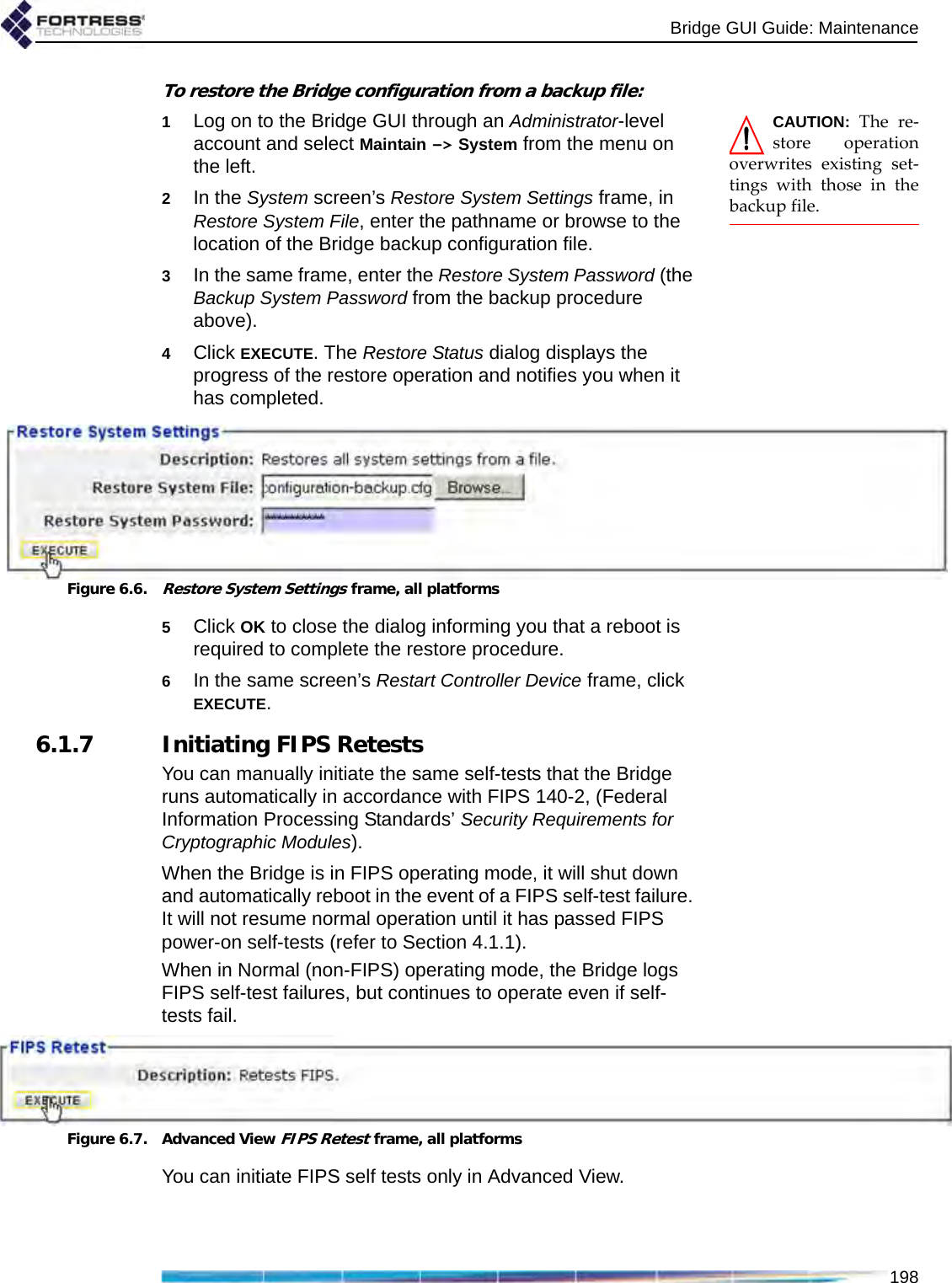
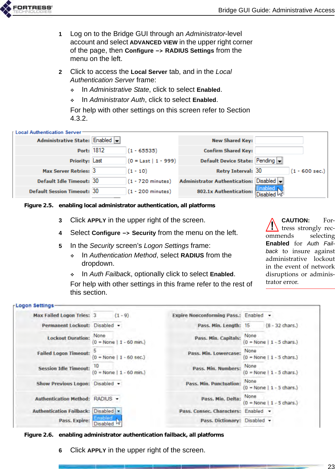
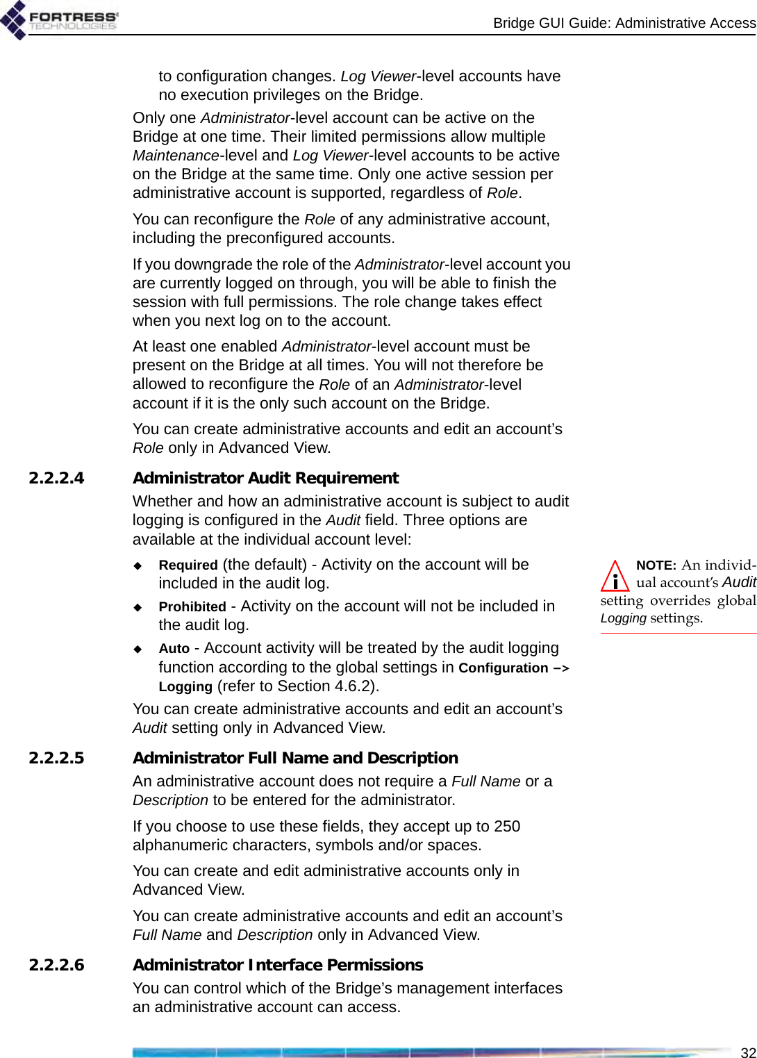
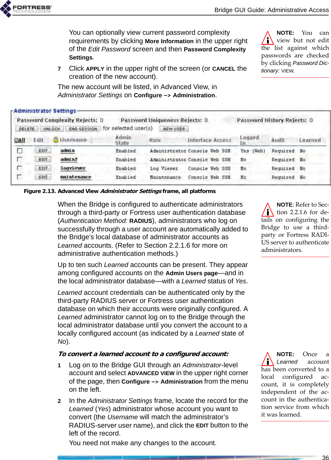
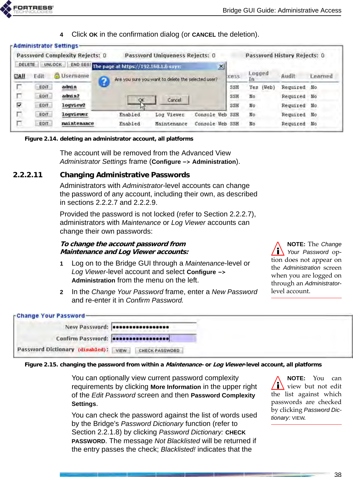
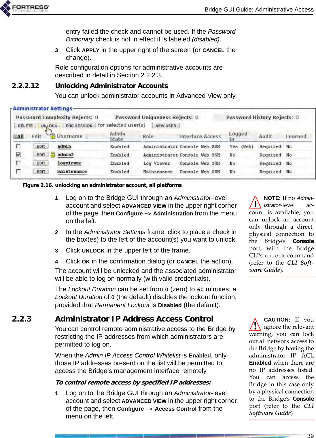
![Bridge GUI Guide: Administrative Access312.2.2.1 Administrator User NamesNOTE: In Ad-vanced View, theUsername for any ac-count listed in Adminis-trator Settings links to aDetailed Statistics dialogfor the account. Refer toSection 5.2 for more in-formation. At the time a new administrative account is created, you must provide a Username. Once established, the Username associated with an administrative account cannot be changed.Administrator user names must be unique on the Bridge. They are case sensitive, can be from 1 to 32 characters long, and can include spaces and any of the symbols in the set: ~ ! @ # $ % ^ & *( ) _ - + = { } [ ] | \ : ; < > , . ? / (excludes double and single quotation marks).An administrative account with a Learned state of Yes acquires the Username configured for the associated administrator in the third-party or Fortress RADIUS server (refer to Section 2.2.2.8).You can create new administrative accounts only in Advanced View.2.2.2.2 Account Administrative StatePreconfigured and newly added administrative accounts are Enabled by default. If you change an account’s Administrative State to Disabled, it will no longer be usable. If the associated administrator attempts to log on to a Disabled account, the Logon to Fortress Security System screen will be returned with an error message. If you re-enable the account, the administrator will be allowed to log on normally.At least one enabled Administrator-level account must be present on the Bridge at all times. You will not therefore be allowed to disable an Administrator-level account if it is the only such account on the Bridge.You can create new administrative accounts and edit them only in Advanced View, but you can change the Admin State of preconfigured accounts in both views.2.2.2.3 Administrative RoleAn administrative account can be configured for one of three possible administrative roles:NOTE: Log Viewerand Maintenanceadministrators canchange their own pass-words, provided theiraccount passwords arenot locked (refer to Sec-tion 2.2.2.7).Administrator accounts provide unrestricted access to the Bridge. Administrator-level users can configure all functions and view all system and configuration information on the Bridge.Maintenance accounts provide view-only access to complete system and configuration information but no reconfiguration access. A maintenance administrator’s execution privileges are confined to using the network diagnostic tools on Maintain -> Network, resetting Secure Clients and controller device sessions, rebooting the Bridge, and generating a support package.Log Viewer accounts provide view-only access to high-level system health indicators and any log messages unrelated](https://usermanual.wiki/Fortress-Technologies/ES820.GUI-Guide/User-Guide-1413931-Page-46.png)
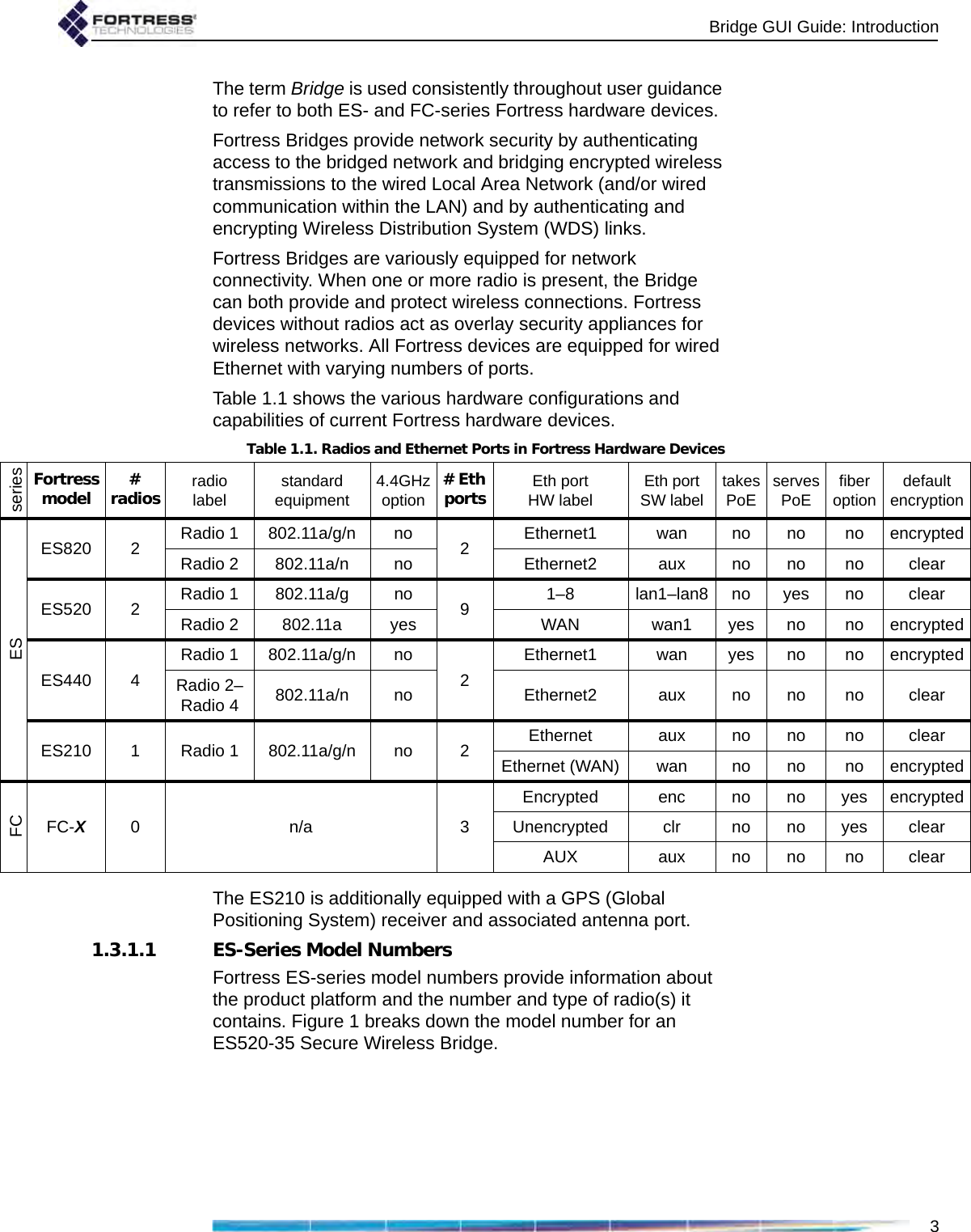
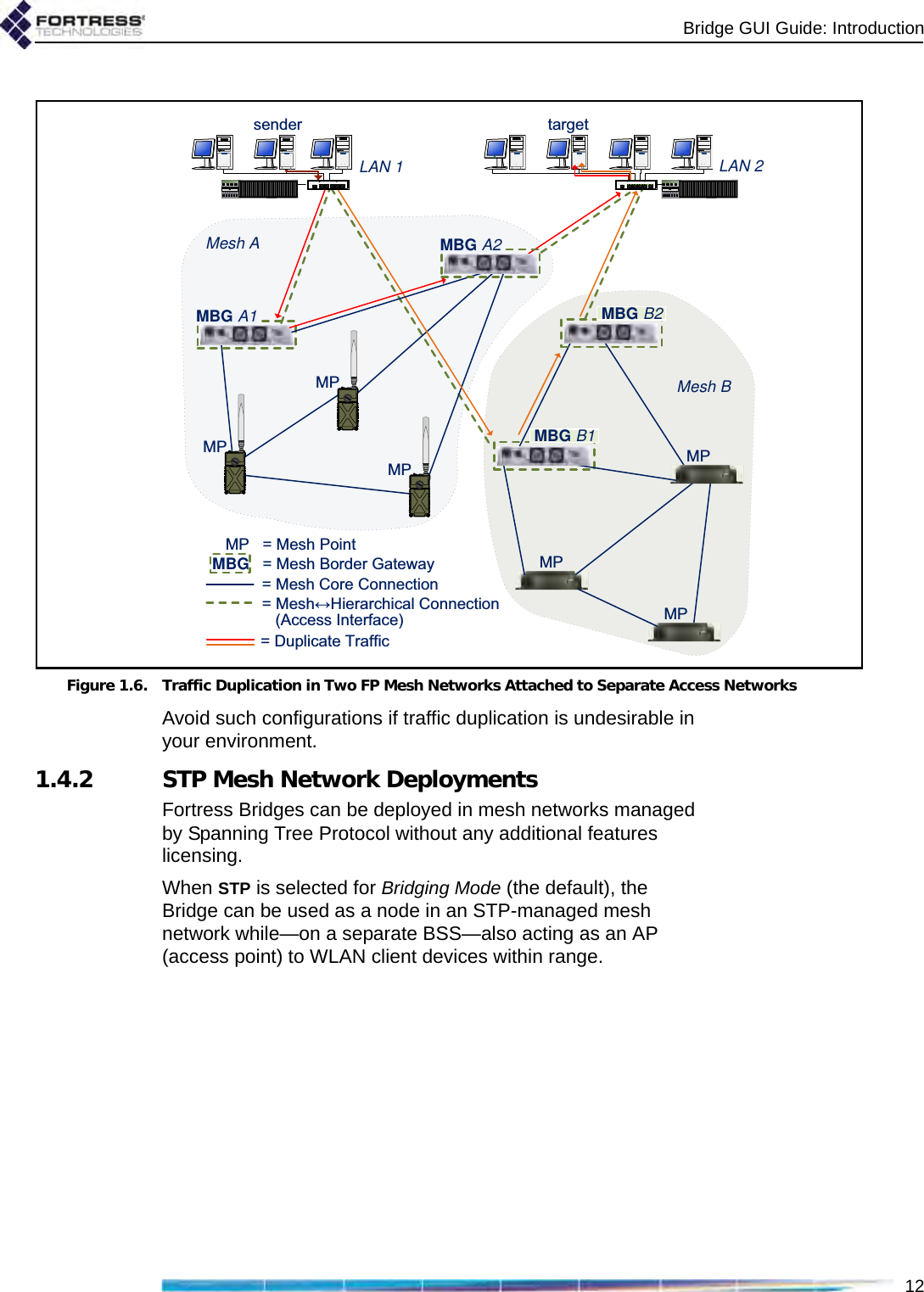
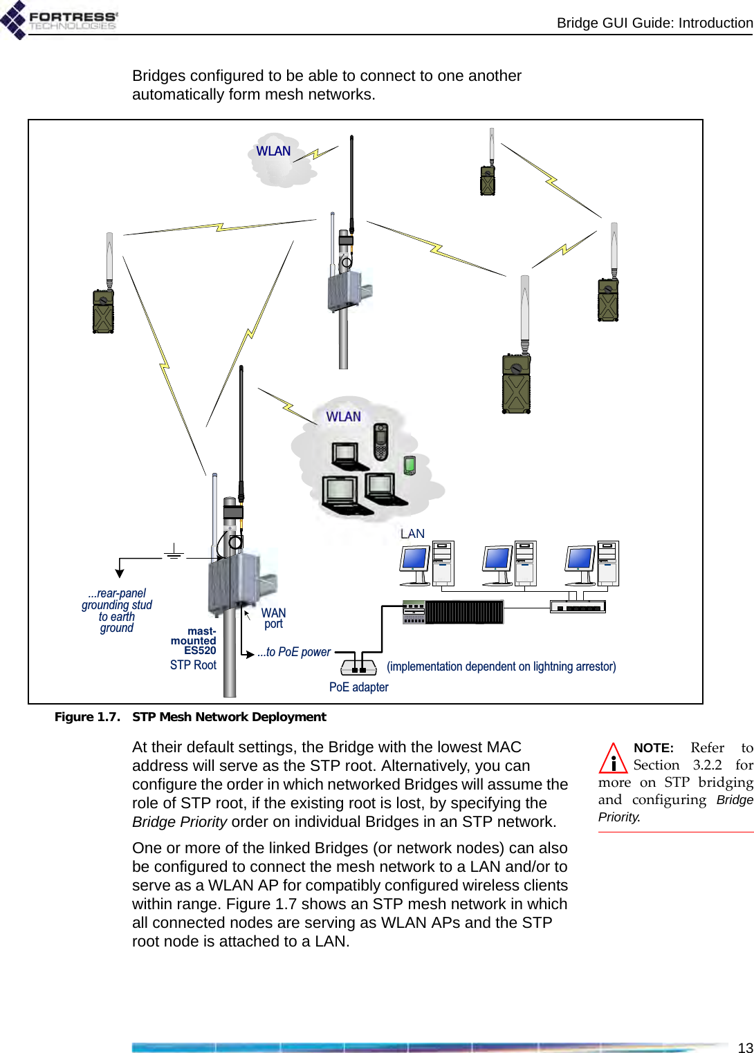
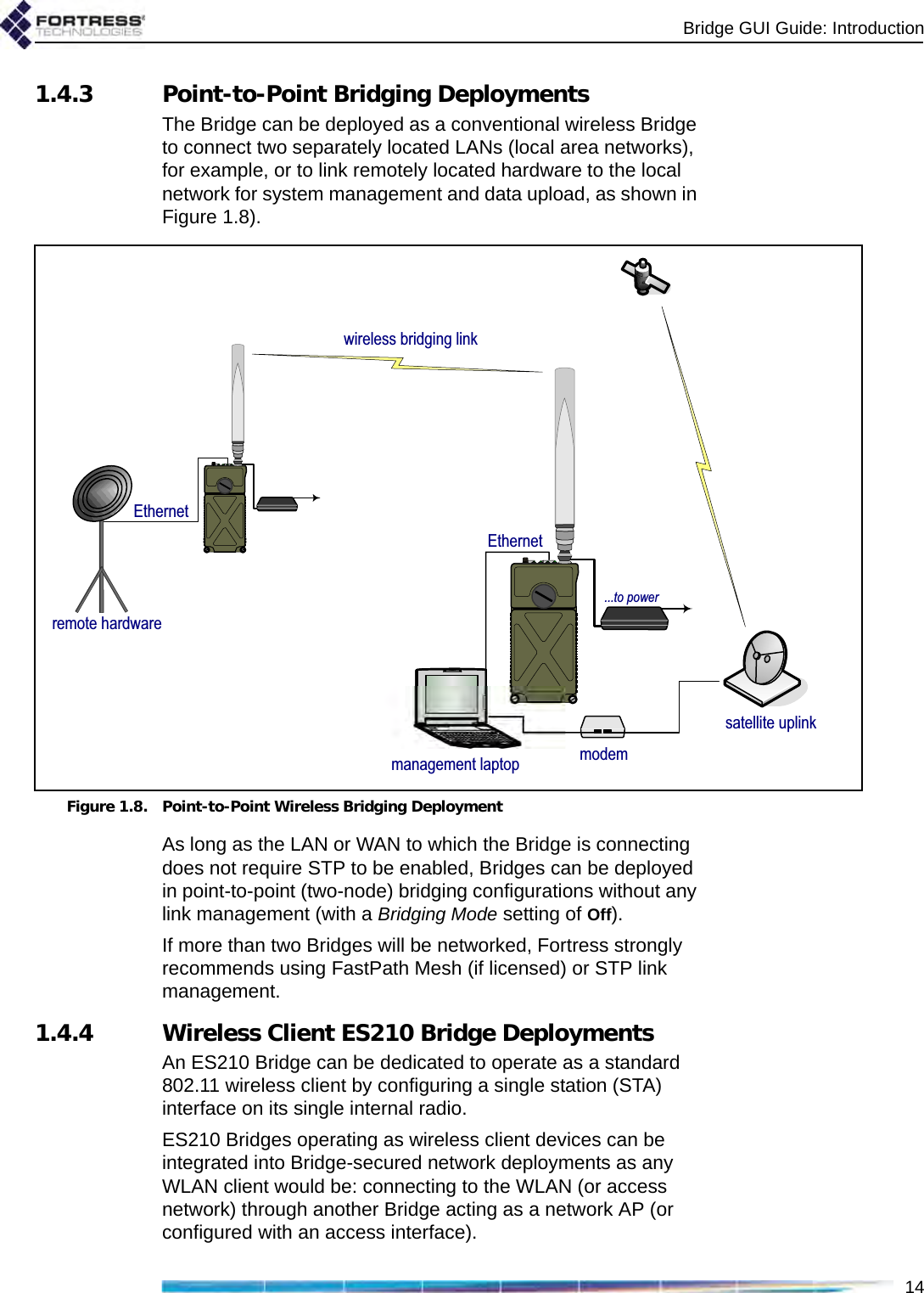
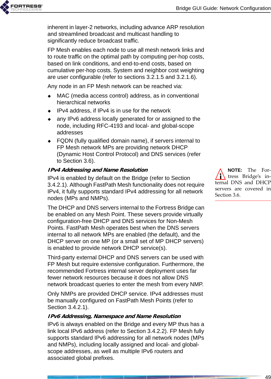
![Bridge GUI Guide: Network Configuration48support the mesh network and user controls to configure and tune it.NOTE: FastPathMesh and STP linkmanagement are mutu-ally incompatible. Net-worked Bridges must allbe configured to use thesame Bridging Mode.Unless the network can be physically configured to eliminate any possibility of bridging loops (multiple OSI [open systems interconnection] layer-2 paths to the same device), either FastPath Mesh or STP must be used when Bridges are deployed in a mesh network.Supported FastPath Mesh and STP network topologies are illustrated and described in detail in Chapter 1.3.2.1 FastPath Mesh BridgingNodes on a FastPath Mesh network are of two basic types:Mesh Point (MP) - a Fortress Bridge with FastPath Mesh enabledNon-Mesh Point (NMP) - any node that is not an MPFP Mesh nodes can connect over their Ethernet ports or radio BSSs. An FP Mesh interface must be configured for the type of connection it provides: MPs connect to other MPs only on Core interfaces. NMPs connect to MPs only on Access interfaces A given interface can be of only one type; so MPs and NMPs cannot share an interface. Per-port FastPath Mesh Mode settings for radio BSSs and Ethernet ports are described in sections 3.3.4.4 and 3.7.3, respectively. All MPs on a given FP Mesh network are peers. Directly connected MPs are neighbors.An MP that serves as a link between the FP Mesh network and a conventional hierarchical network is a Mesh Border Gateway (MBG).An FP Mesh network presents to NMPs as a flat, OSI layer-2 network, while optimizing operations to eliminate inefficiencies Table 3.1. STP Networks Compared to FastPath Mesh function STP FP Meshself-forming supported supportedself-healing supportedasupportedend-to-end encryption supported supportedall paths available at all times not supported supportedoptimal path selection not supported supportedautomatic IPv6 mesh addressing not supported supportedindependent DNS and .ftimesh.local domain not supported supportedconfigurable network and neighbor cost weighting not supported supporteda. except for STP root node](https://usermanual.wiki/Fortress-Technologies/ES820.GUI-Guide/User-Guide-1413931-Page-63.png)
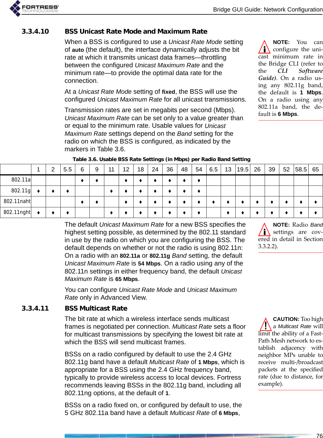
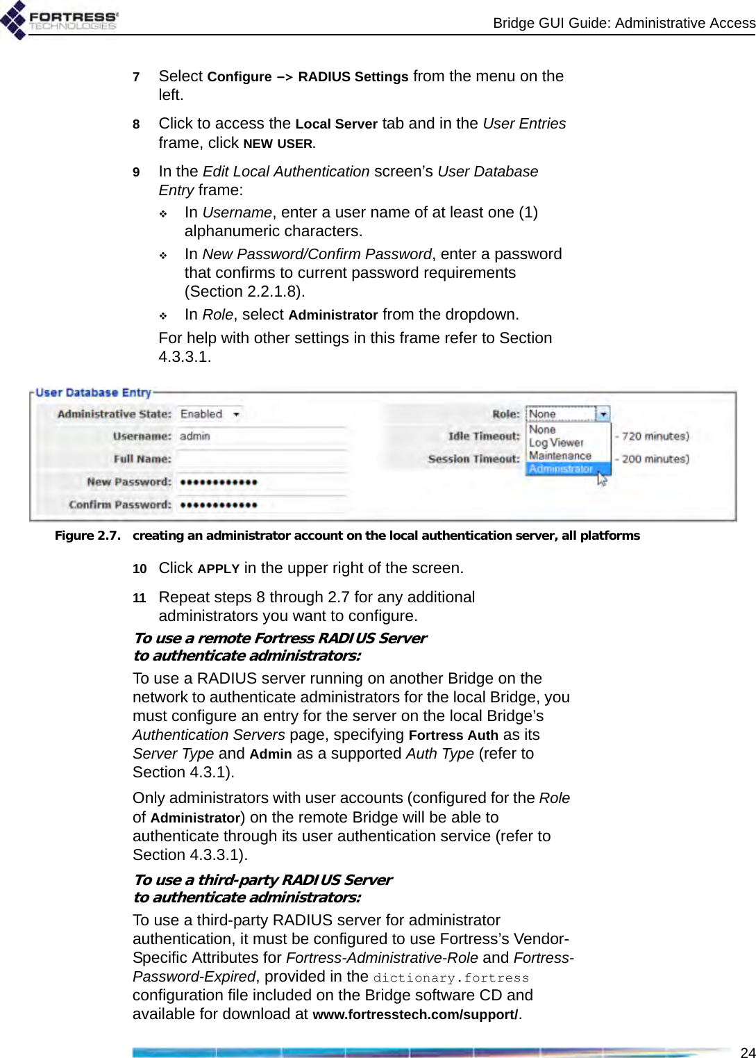
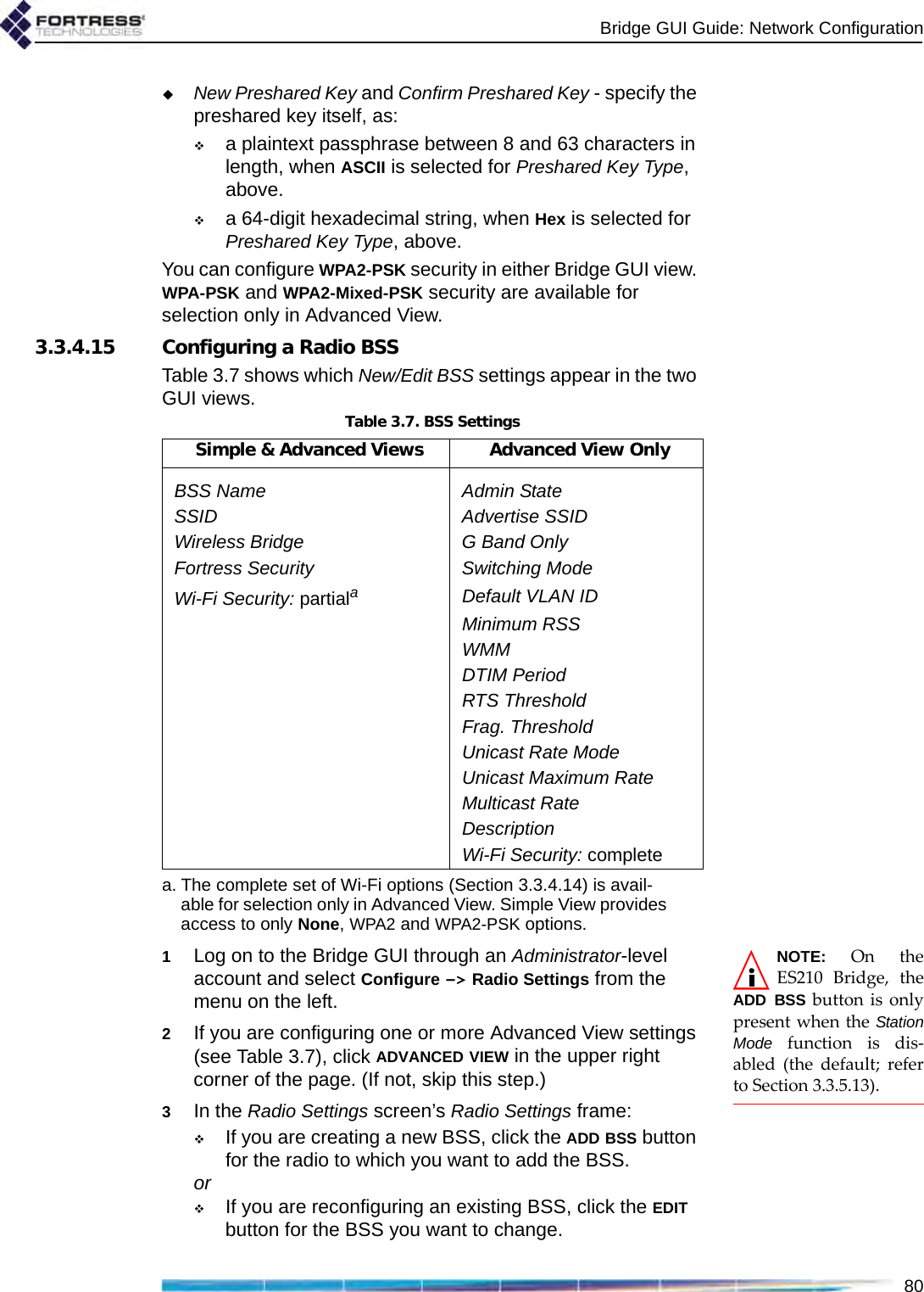
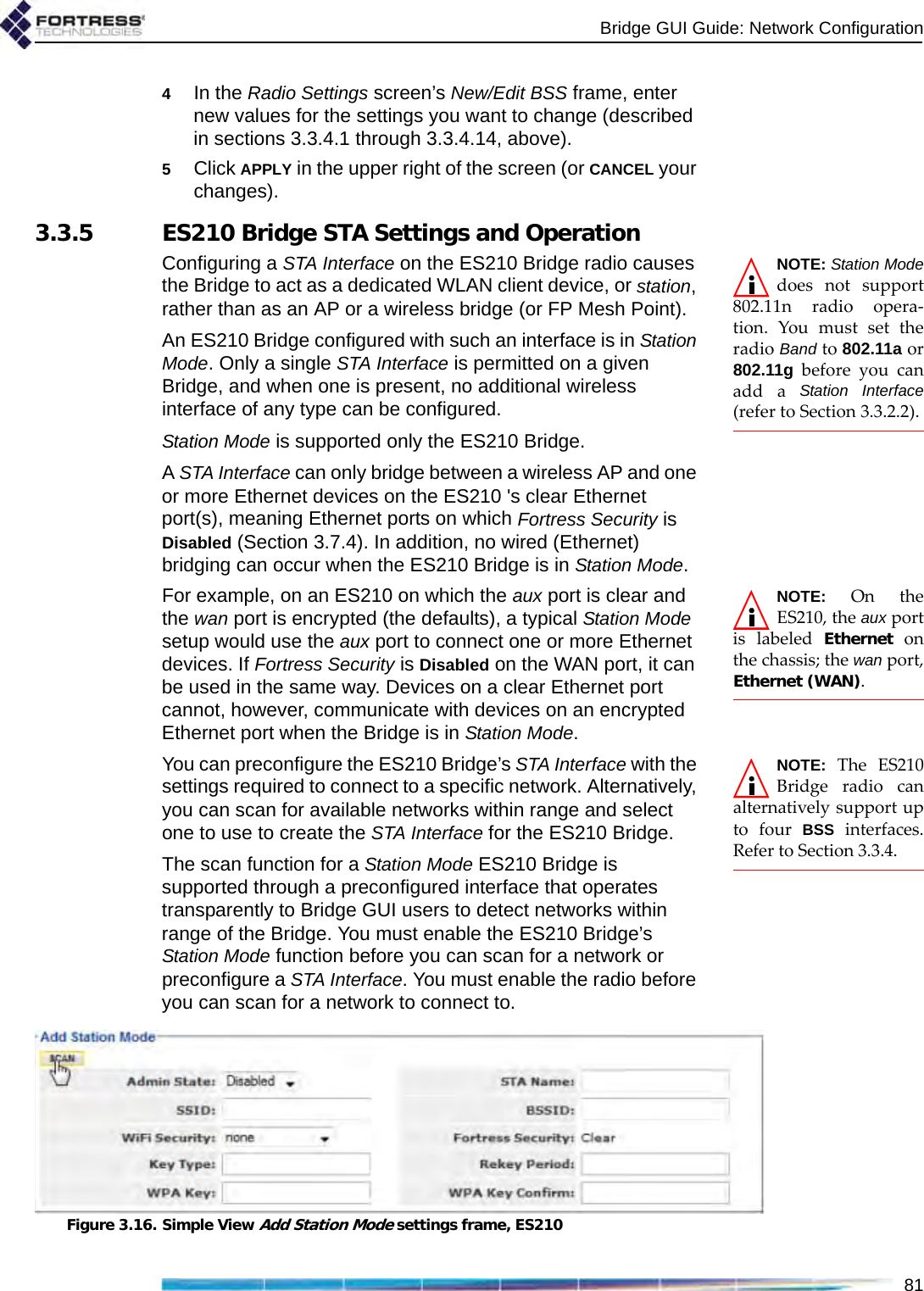
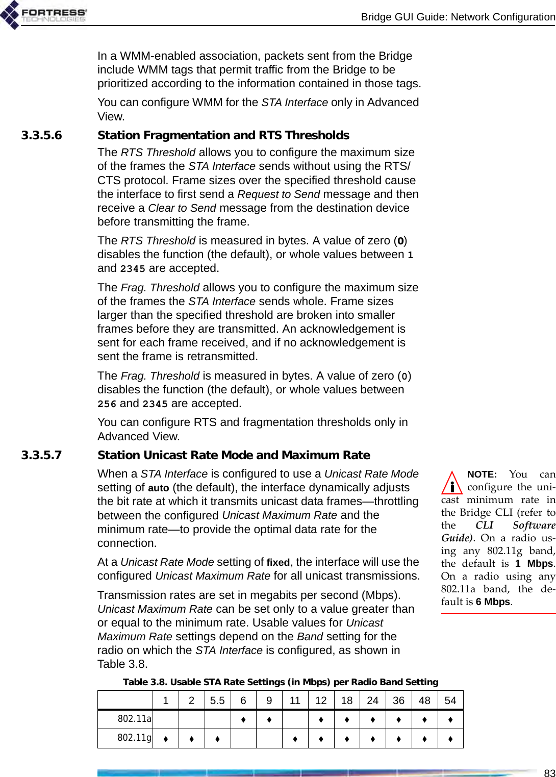
![Bridge GUI Guide: Network Configuration77which is appropriate for a BSS using the 5 GHz frequency band, typically for network bridging. Fortress recommends leaving BSSs in the 802.11a band, including all 802.11na options, at the default of 6. If the BSS will provide mesh network bridging in the 5 GHz 802.11a band, Fortress recommends a Multicast Rate of 6Mbps. Set a higher rate only if you are certain that all neighbor links to the BSS can consistently maintain a significantly better data rate than the new Multicast Rate.3.3.4.12 BSS DescriptionYou can optionally provide a Description of the BSS of up to 100 characters. A BSS’s description displays only on the Advanced View Edit BSS frame (Advanced View -> Configure -> Radio Settings -> [BSS Interfaces] EDIT). You can enter a Description for a BSS only in Advanced View.3.3.4.13 BSS Fortress Security SettingTraffic on BSSs Enabled for Fortress Security is subject to Fortress’s Mobile Security Protocol (MSP), as configured on the Bridge itself (refer to Section 4.1).Fortress Security is Enabled on BSSs by default. When a BSS’s Wireless Bridge setting is Enabled (refer to Section 3.3.4.3), its Fortress Security setting is automatically fixed on Enabled and the Fortress Security field is view-only.Disabling Fortress Security on a BSS exempts all traffic on that BSS from Fortress’s Mobile Security Protocol (MSP). Standard Wi-Fi security protocols can be applied to the traffic on a BSS (Section 3.3.4.14, below), regardless of whether the BSS is Enabled or Disabled for Fortress Security.3.3.4.14 BSS Wi-Fi Security SettingsAs an alternative or in addition to Fortress Security, a number of well known security protocols can be applied to the BSSs created on the Bridge.Your selection in the Wi-Fi Security field of the Edit BSS frame determines the additional fields you must configure for that setting—presented dynamically by the Bridge GUI for each possible Wi-Fi Security selection.Wi-Fi Security: NoneIf Fortress Security is disabled on a BSS and it has a Wi-Fi Security setting of None, traffic on that BSS is unsecured.CAUTION: An un-secured wirelessinterface leaves the net-work unsecured.Devices connected to an unsecured BSS send and receive all traffic in the clear.](https://usermanual.wiki/Fortress-Technologies/ES820.GUI-Guide/User-Guide-1413931-Page-92.png)
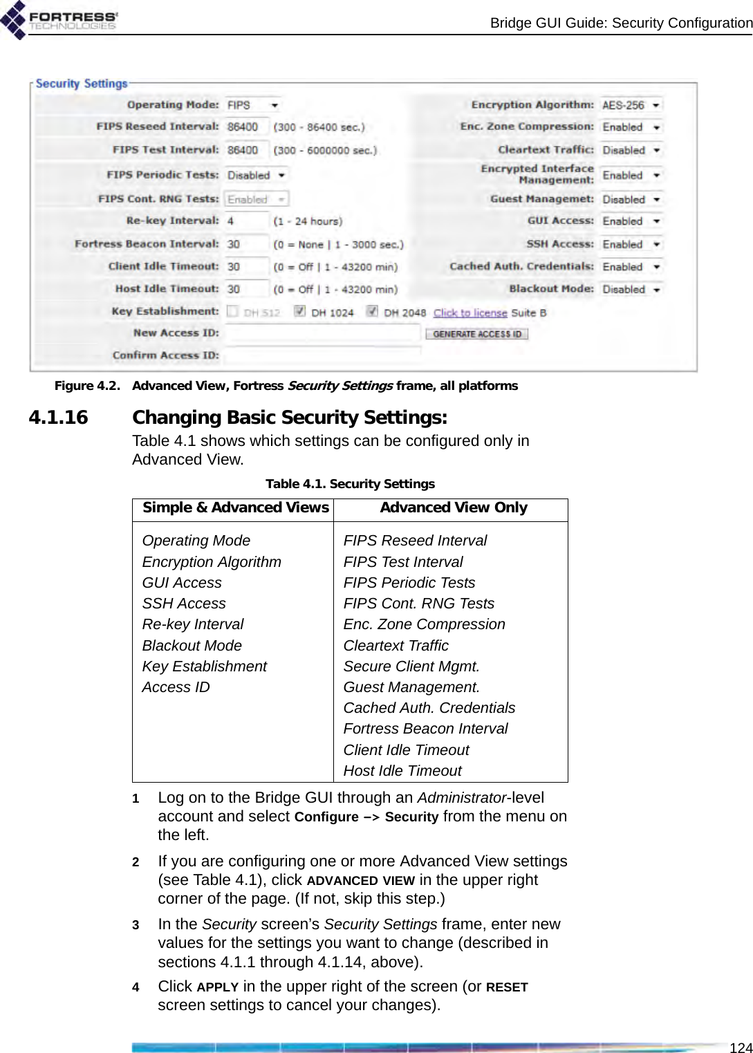
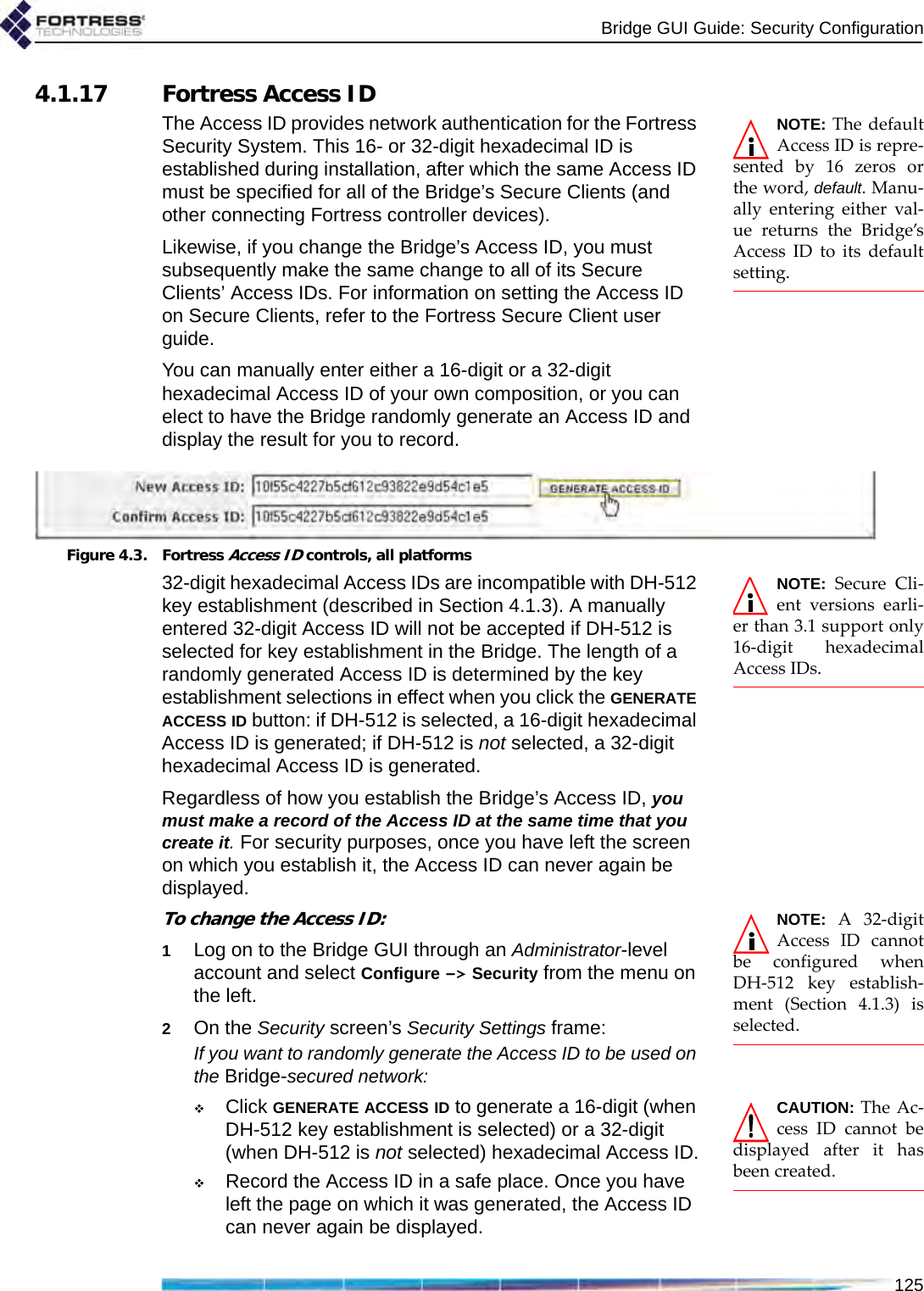
![Bridge GUI Guide: Security Configuration1194.1.3 MSP Key EstablishmentYou can configure the method that the Bridge and its Secure Clients (and other connecting controller devices) use to establish data encryption keys.NOTE: On wire-less networks, sep-arate multicast packetsare sent for each config-ured key group. To max-imize throughput, limitthe number selected. In Normal operating mode (Section 4.1.1) the Bridge supports three Diffie-Hellman groups (DH groups) for key establishment—identified by the size of the modulus, in numbers of bits, used to generate the secret shared key:DH-512 (Normal [non-FIPS] operating mode only)DH-1024 (Normal [non-FIPS] operating mode only)DH-2048 (default selection)When operating the Bridge in FIPS mode (Section 4.1.1), you cannot use DH-512 or DH-1024 key establishment, because the smaller Diffie-Hellman group moduli are no longer compliant with FIPS 140-2 Security Level 2.When NSA (National Security Agency) Suite B5 cryptography is licensed on the Bridge, an additional elliptic curve Diffie-Hellman key establishment method is available for selection: Suite B (specified by the NSA as compliant with the Suite B set of cryptographic algorithms). When Suite B is not licensed on the Bridge, the Bridge GUI displays a link to the features licensing page (refer to Section 6.3). While a Secure Client can employ only one key establishment option at a time, the Bridge supports multiple key establishment selections, allowing connecting Clients to use any enabled key establishment option.NOTE: Secure Cli-ent versions earli-er than 3.1 support onlyDH-512 key establish-ment. If you need tosupport pre-3.1 SecureClient devices, youmust include DH-512.A Secure Client logging on to the Bridge must use a key establishment option enabled on the Bridge. For information on configuring key establishment on Fortress Secure Clients, refer to the Secure Client’s user guide.When two Fortress controller devices are connected, they will negotiate keys using the highest security option mutually supported by the devices. When Suite B key establishment has been licensed on the Bridge, this option represents the highest available security. NOTE: DH-512 keyestablishment can-not be selected when a32-digit Access ID (Sec-tion 4.1.17) is in effect.Larger key moduli equate to more security for the standard Diffie-Hellman group key establishment options, as well. DH-512 is therefore the least secure DH group, and if you do not need the Bridge to support Secure Client versions earlier than 3.1 (which require DH-512), Fortress recommends more secure key establishment. Larger key moduli result in somewhat longer initial connection times.Refer to the Suite B requirements specific to your site and implementation for guidance on Suite B.5. Refer to Footnote 1 on page 2.](https://usermanual.wiki/Fortress-Technologies/ES820.GUI-Guide/User-Guide-1413931-Page-134.png)
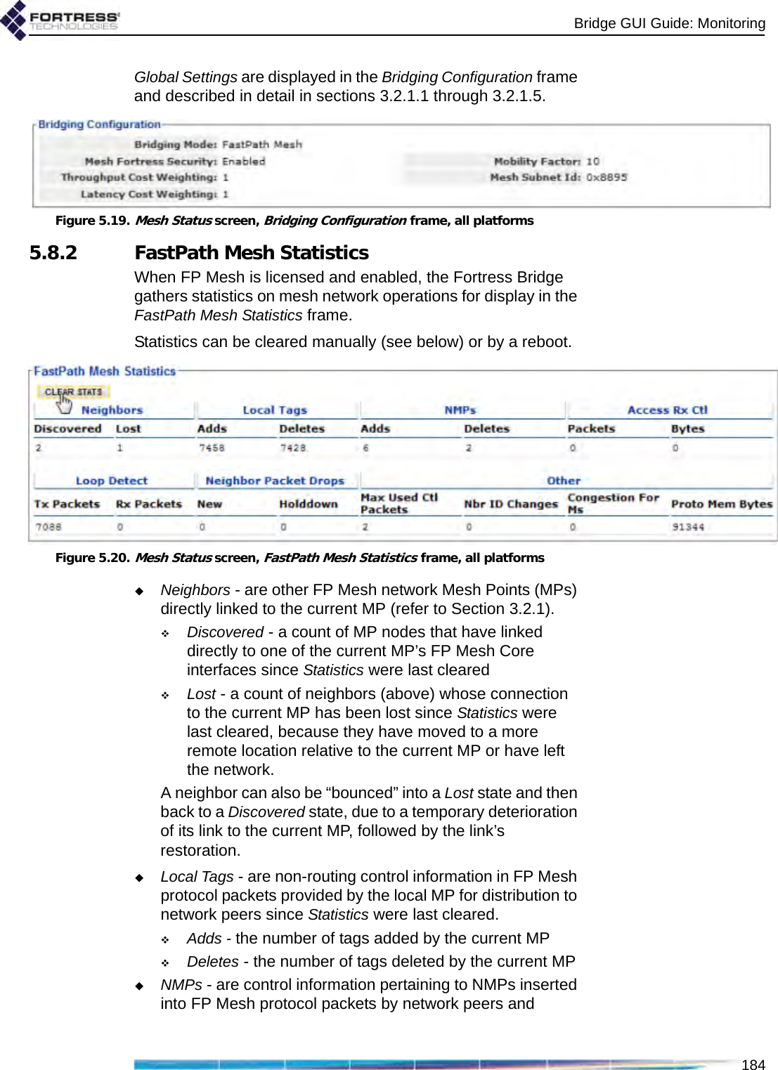
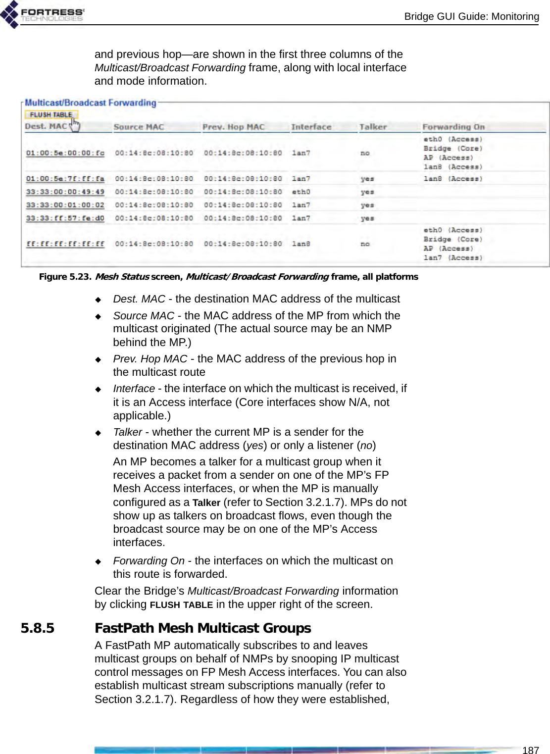
![Bridge GUI Guide: Monitoring1865.8.3 FastPath Mesh Peers and NeighborsAll MP nodes on the FP Mesh network, including the current MP, are shown in the Peers frame of the Mesh Status screen. MPs directly connected to the current MP are shown in Neighbors.For each MP of either type the Bridge GUI displays:MAC Address - the MP’s Media Access Control addressName - the MP’s hostnameCost - the lowest cost associated in FP Mesh of reaching the remote MP from the current MPPath cost is additive by hops. The current Bridge has a constant Cost of 0 (zero). Wired interfaces cost much less than wireless. A Cost of 4,294,967,295 is “infinite”: the MP is unreachable, a transient condition just before the MP leaves the list. The greater the cost to a peer, the less preferred is any route to or through that peer.IP Address - the IPv4 address of the MPIPv6 Addresses - all IPv6 addresses of the MP, including the link local address, the RFC-4193 unique local address, and any other user-configured or auto-configured global addresses.Figure 5.21.Mesh Status screen, Peers frame, all platformsFor each MP listed on Peers, under NMPs, the MAC addresses of any connected Non-Mesh Points (devices on the peer MP’s Access interface[s]) are shown.Figure 5.22.Mesh Status screen, Neighbors frame, all platformsFor each of the current MP’s Neighbors, the number of connected NMPs is displayed under NMP Count, followed by the Interfaces over which the current MP is connected to the neighbor. An MP can be connected to a neighbor over multiple interfaces.5.8.4 Multicast/Broadcast ForwardingThe three values that FP Mesh takes into account when making multicast forwarding decisions—destination, source](https://usermanual.wiki/Fortress-Technologies/ES820.GUI-Guide/User-Guide-1413931-Page-201.png)