FreeWave Technologies 42182112519 902MHz to 928MHz Transceiver User Manual LUM0002AG Rev A

FreeWave Technologies Inc. 902MHz to 928MHz Transceiver LUM0002AG Rev A

Contents

Exhibit D Users Manual per 2 1033 b3
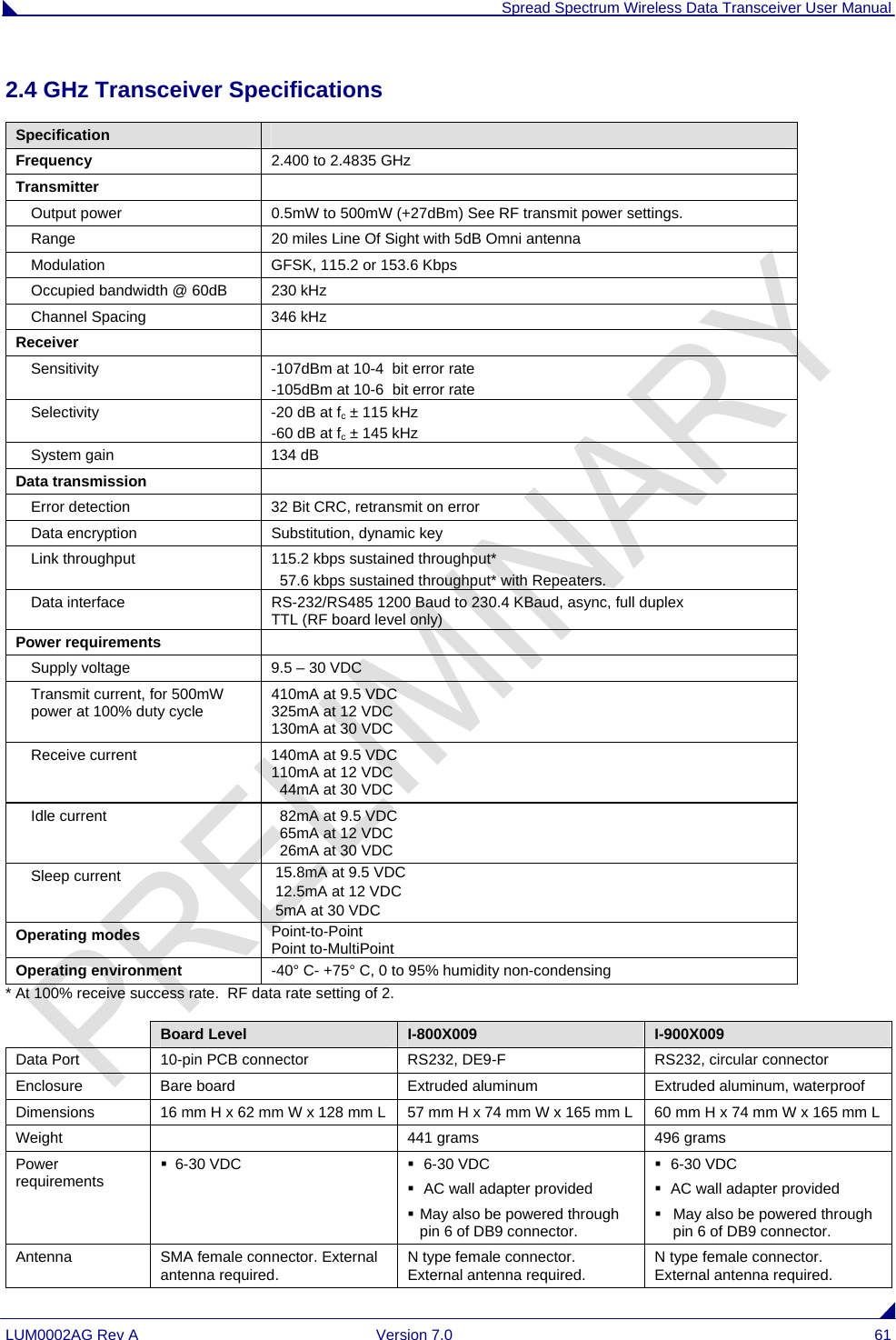
 Spread Spectrum Wireless Data Transceiver User Manual LUM0002AG Rev A  Version 7.0  i       Spread Spectrum  Wireless Data Transceiver User Manual Version 7.0    FreeWave Technologies, Inc. 1880 South Flatiron Court Boulder, CO 80301 (303) 444-3862 (303) 786-9948 Fax www.FreeWave.com        SPREAD SPECTRUM WIRELESS DATA TRANSCEIVER USER MANUAL  Copyright © 1995-2008 by FreeWave Technologies, Inc. All rights reserved. Published 2008.
 Spread Spectrum Wireless Data Transceiver User Manual LUM0002AG Rev A  Version 7.0  ii   WARRANTY FreeWave Technologies warrants the FreeWave Wireless Data Transceiver against defects in materials and manufacturing for a period of two years from the date of purchase.  In the event of a Product failure due to materials or workmanship, FreeWave will, at its discretion, repair or replace the Product. In no event will FreeWave Technologies Inc., its suppliers, and its licensors be liable for any damages arising from the use of or inability to use this Product.  This includes business interruption, loss of business information, or other loss which may arise from the use of this Product.  Please be advised that OEM customer’s warranty periods may vary. Warranty Policy may not apply: 1.  If Product repair, adjustments or parts replacements is required due to accident, neglect, unusual physical, electrical or electromagnetic stress. 2.  If Product is used outside of FreeWave specifications. 3.  If Product has been modified, repaired or altered by Customer unless FreeWave specifically authorized such alterations in each instance in writing.  This includes the addition of conformal coating.         The Warranty period begins from the date of shipment and is defined per the Standard Warranty Policy stated above. Special Rate Replacement Option  A special rate replacement option is offered to non-warranty returns or upgrades.  The option to purchase the replacement unit at this special rate is only valid for that RMA, (Return Material Authorization).  The special replacement rate option expires if not exercised within 30 days of final disposition of RMA. RESTRICTED RIGHTS Microsoft and Windows are registered trademarks of the Microsoft Corporation. pcANYWHERE is a registered trademark of Symantec Corporation. Other product names mentioned in this manual may be copyrights, trademarks, or registered trademarks of their respective companies and are hereby acknowledged. Information in this document is subject to change without notice. The information contained in this document is proprietary and confidential to FreeWave Technologies, Inc. This manual is for use by purchasers and other authorized users of the FreeWave™ Spread Spectrum Wireless Data Transceiver only.  No part of this document may be reproduced or transmitted in any form or by any means, electronic or mechanical, or for any purpose without the express written permission of FreeWave Technologies, Inc. FreeWave’s Spread Spectrum Wireless Data Transceivers are made in the United States of America. Printed in the United States of America.
 Spread Spectrum Wireless Data Transceiver User Manual LUM0002AG Rev A  Version 7.0  iii This product is licensed by The United States. Diversion contrary to U.S. law is prohibited. Shipment or re-export of this product outside of The United States may require authorization by the U.S. Bureau of Export Administration. Please contact FreeWave Technologies for assistance and further information. UL NOTIFICATION Model# FGR2 is undergoing testing to be suitable for use in Class 1, Division 2, Groups A, B, C, and D or non-hazardous locations only. Input voltage for Model# FGR2 is 6 to 30 volts DC.  Model# FGRO9CSU is suitable for use in Class 1, Division 2, Groups A, B, C, and D or non-hazardous locations only. Input voltage for Model# FGRO9CSU is 6 to 30 volts DC.  Model# DGRO9RFS is suitable for use in Class 1, Division 2, Groups A, B, C, and D or non-hazardous locations only. Input voltages for Model# DGRO9RFS are determined by the label on the bottom of the board. If the board has Label A shown below the input voltage is 6 to 14 volts DC.  If the board has Label B shown below the input voltage is 6 to 14 volts DC at a maximum baud rate of 57.6 KBaud or 6 to 18 volts DC at a maximum baud rate of 19.2 KBaud, operation mode of MultiPoint Slave or MultiPoint Slave/Repeater only.
 Spread Spectrum Wireless Data Transceiver User Manual LUM0002AG Rev A  Version 7.0  iv FCC NOTIFICATIONS This device complies with part 15 of the FCC rules. Operation is subject to the following two conditions: 1) This device may not cause harmful interference and 2) this device must accept any interference received, including interference that may cause undesired operation. This device must be operated as supplied by FreeWave Technologies, Inc. Any changes or modifications made to the device without the express written approval of FreeWave Technologies may void the user's authority to operate the device. CAUTION:   The FGR series transceivers have a maximum transmitted output power of 955mW. The FGR2 series transceivers have a maximum transmitted output power of 1000mW. It is recommended that the transmit antenna be kept at least 23 cm away from nearby persons to satisfy FCC RF exposure requirements.   The “I”-series transceiver have maximum transmitted output power of 500mW. It is recommended that the transmit antenna be kept at least 23 cm away from nearby persons to satisfy FCC RF exposure requirements. This equipment has been tested and found to comply with the limits for a Class B digital device, pursuant to part 15 of the FCC Rules. These limits are designed to provide reasonable protection against harmful interference in a residential installation. This equipment generates, uses, and can radiate radio frequency energy and, if not installed and used in accordance with the instructions, may cause harmful interference to radio communications. However, no guarantee shall be made that interference will not occur in a particular installation. If this equipment does cause harmful interference to radio or television reception, which can be determined by turning the equipment off and on, the user is encouraged to try to correct the interference by one or more of the following measures: •  Reorient or relocate the receiving antenna. •  Increase the separation between the equipment and receiver. •  Connect the equipment into an outlet on a circuit different from that to which the receiver is connected. •  Consult the dealer or an experienced radio/TV technician for help. Note:   Whenever any FreeWave Technologies module is placed inside an enclosure a label must be placed on the outside of that enclosure which includes the module's FCC ID.
 Spread Spectrum Wireless Data Transceiver User Manual LUM0002AG Rev A  Version 7.0  v Table of Contents ABOUT FREEWAVE TRANSCEIVERS.................................................................................................................7 CHOOSING POINT-TO-POINT OR POINT-TO-MULTIPOINT OPERATION ........................................................................8 QUICK START ON A POINT-TO-MULTIPOINT NETWORK ..........................................................................9 POINT-TO-MULTIPOINT OPERATION LED'S. ..............................................................................................................9 QUICK START ON A POINT-TO-POINT NETWORK......................................................................................10 POINT-TO-POINT OPERATION LED’S........................................................................................................................10 CHOOSING A LOCATION FOR THE TRANSCEIVERS..................................................................................11 SETTING UP THE TRANSCEIVER USING HYPERTERMINAL ...................................................................12 ACCESSING HYPERTERMINAL’S SETUP MENU .........................................................................................................12 CONNECTING AND DISCONNECTING FROM HYPERTERMINAL...................................................................................16 TROUBLESHOOTING HYPERTERMINAL.....................................................................................................................17 SETTING UP A TRANSCEIVER ...........................................................................................................................18 OPERATION MODE....................................................................................................................................................18 SET OPERATION MODE.............................................................................................................................................20 Using the Point-to-Point Slave/Master Switchable Operation Mode (Mode 6) ..................................................20 Script File or AT commands................................................................................................................................21 BAUD RATE..............................................................................................................................................................24 SET BAUD RATE.......................................................................................................................................................24 CALL BOOK..............................................................................................................................................................27 EDIT CALL BOOK .....................................................................................................................................................27 Programming Point-to-Point Extended Call Book to Use Three or Four Repeaters ..........................................28 Programming Point-to-MultiPoint Call Book .....................................................................................................29 Programming Point-to-MultiPoint Extended Call Book .....................................................................................29 RADIO TRANSMISSION CHARACTERISTICS ...............................................................................................................30 EDIT RADIO TRANSMISSION CHARACTERISTICS.......................................................................................................30 FreqKey in 900 MHz Transceivers......................................................................................................................30 (0) Hop Table Version .........................................................................................................................................31 (1) Hop Table Size...............................................................................................................................................31 (2) Hop Freq Offset .............................................................................................................................................31 (3) Frequency Zone..............................................................................................................................................32 FreqKey in 2.4 GHz Transceivers .......................................................................................................................34 (0) Hop Table Version .........................................................................................................................................34 (1) Hop Table Size...............................................................................................................................................34 (2) Hop Freq Offset .............................................................................................................................................34 (3) Frequency Zone..............................................................................................................................................35 (4) Government Rules..........................................................................................................................................35 (1) Max Packet Size and (2) Min Packet Size......................................................................................................36 (3) Xmit Rate........................................................................................................................................................37 (4) RF Data Rate .................................................................................................................................................37 (5) RF Xmit Power...............................................................................................................................................38 (6) Slave Security.................................................................................................................................................38 (7) RTS to CTS.....................................................................................................................................................38 (8) Retry Time Out...............................................................................................................................................39 (9) Lowpower Mode.............................................................................................................................................39 (A) High Noise.....................................................................................................................................................40 (B) MCU speed....................................................................................................................................................40 (C) Remote LED ..................................................................................................................................................40 SHOW RADIO STATISTICS.........................................................................................................................................41 Number of Disconnects........................................................................................................................................41
 Spread Spectrum Wireless Data Transceiver User Manual LUM0002AG Rev A  Version 7.0  vi Antenna Reflected Power.....................................................................................................................................41 Transmit Current (mA)........................................................................................................................................41 Average Noise Level ............................................................................................................................................41 Average Signal Level...........................................................................................................................................42 Overall Rcv Rate (%)...........................................................................................................................................42 Radio Temperature..............................................................................................................................................42 MULTIPOINT PARAMETERS ......................................................................................................................................42 EDIT MULTIPOINT PARAMETERS..............................................................................................................................42 (0) Number Repeaters..........................................................................................................................................43 (1) Master Packet Repeat ....................................................................................................................................43 (2) Max Slave Retry .............................................................................................................................................44 (3) Retry Odds .....................................................................................................................................................44 (4) DTR Connect..................................................................................................................................................44 (5) Repeater Frequency.......................................................................................................................................44 (6) Network ID.....................................................................................................................................................44 (8) MultiMaster Synch.........................................................................................................................................45 (9) 1 PPS Enable/Delay.......................................................................................................................................45 (A) Slave/Repeater...............................................................................................................................................45 (B) Diagnostics....................................................................................................................................................45 (C) Subnet ID.......................................................................................................................................................46 (D) Radio ID........................................................................................................................................................47 (E) Local Mode....................................................................................................................................................47 (G) Radio Name...................................................................................................................................................47 OVERLAPPING MULTIPOINT NETWORKS ..................................................................................................................47 PASSWORDS .............................................................................................................................................................48 SETTING A PASSWORD..............................................................................................................................................48 Changing a Password..........................................................................................................................................48 Disabling a Password..........................................................................................................................................48 TIME DIVISIBLE MULTIPLE ACCESS (TDMA) ..........................................................................................................48 ADDITIONAL SETTINGS ......................................................................................................................................49 LOW BAUD RATES....................................................................................................................................................49 SETUP TIMEOUT .......................................................................................................................................................49 FACTORY DEFAULT SETTINGS.........................................................................................................................50 EXAMPLES OF DATA COMMUNICATION LINKS.........................................................................................51 ADDITIONAL TRANSCEIVER INFORMATION...............................................................................................54 OPERATIONAL RS-422 AND RS-485 INFORMATION .................................................................................................54 RS-485 Half Duplex Pin-Outs..............................................................................................................................55 RS-422 and RS-485 Full Duplex Pin-Outs Waterproof Enclosure......................................................................55 RS-485 Half Duplex Pin-Outs..............................................................................................................................55 RS232 PIN ASSIGNMENTS ........................................................................................................................................56 RF BOARD LEVEL PINOUT .......................................................................................................................................57 XGR-115WC WATERPROOF ENCLOSURE PIN OUT FOR CABLE ASC0613WW.........................................................58 900 MHZ TRANSCEIVER SPECIFICATIONS ................................................................................................................59 2.4 GHZ TRANSCEIVER SPECIFICATIONS ..................................................................................................................61 OEM FULL SIZE BOARD LEVEL MECHANICAL DRAWING........................................................................................62 OEM MINI- BOARD LEVEL MECHANICAL DRAWING ...............................................................................................63 FGR ERRATA DATA...............................................................................................................................................64 FREEWAVE TECHNICAL SUPPORT .................................................................................................................64
 Spread Spectrum Wireless Data Transceiver User Manual LUM0002AG Rev A  Version 7.0  7 About FreeWave Transceivers  FreeWave transceivers operate in virtually any environment where RS232 data communications occur. A pair of transceivers function as a 9-pin null modem cable. If the FreeWave transceivers are to be used in an application where a null modem cable is used, such as communication between two computers, then the FreeWave transceivers can be connected directly. If FreeWave transceivers are to be used to replace a straight-through RS232 cable, then a null modem cable must be placed between the transceiver and the DTE instrument to which it is connected.
 Spread Spectrum Wireless Data Transceiver User Manual LUM0002AG Rev A  Version 7.0  8 Choosing Point-to-Point or Point-to-MultiPoint Operation A Point-to-Point network is limited to one Master and one Slave transceiver.  Up to 4 Repeaters may be added to extend the reach of the network, but no other Master or Slave may be added.  In a Point-to-MultiPoint network (also referred to as MultiPoint network) the transceiver, designated as a Master, is able to simultaneously communicate with numerous Slaves. In its simplest form, a MultiPoint network functions with the Master broadcasting its messages to all Slaves and the Slaves responding to the Master when given data by the device connected to the data port. It is important to note the differences between Point-to-Point and MultiPoint networks. In a Point-to-Point network all packets are acknowledged, whether sent from the Master to the Slave or from the Slave to the Master. In a MultiPoint network, outbound packets from the Master or Repeater to Slaves or other Repeaters are sent a set number of times determined by the user.  The receiving transceiver, Slave or Repeater, will accept the first packet received that passes the 32 bit CRC. However, the packet is not acknowledged. On the return trip to the Master, all packets sent are acknowledged or retransmitted until they are acknowledged. Therefore, the return link in a MultiPoint network is generally very robust. Traditionally, a MultiPoint network is used in applications where data is collected from many instruments and reported back to one central site. As such, the architecture of such a network is different from Point-to-Point applications. The number of radios in a MultiPoint network is influenced by the following parameters: 1.  Size of the blocks of data. The longer the data blocks, the smaller the network capacity. 2.  Baud rate. 3.  The amount of contention between Slaves. Polled Slaves vs. timed Slaves.   4.  Use of Repeaters. Using the Repeater setting in a MultiPoint network will decrease overall network capacity by 50%. For example, if the network will be polling Slaves once a day to retrieve sparse data, several hundred Slaves could be configured to a single Master. However, if each Slave will be transmitting data at greater levels, then fewer Slaves should be linked to the Master.  The overall network will be closer to capacity with fewer Slaves. For examples and additional information on data communication links, see the section Examples of Data Communication Links later in this document.
 Spread Spectrum Wireless Data Transceiver User Manual LUM0002AG Rev A  Version 7.0  9 Quick Start on a Point-to-MultiPoint Network The following is a quick start guide for setting up two transceivers in Point-to-MultiPoint mode.  This mode allows for a Master to communicate with several Repeaters and Slaves simultaneously.  1.  Connect the transceiver to the serial port of a computer either through a serial cable or via the diagnostics cable. Make sure to connect the radio to a power source (typically, 6 to 30 VDC). 2.  Open up a Hyper Terminal session. •  Use the following settings in connecting with hyper terminal •  Connect to COMx (where 'x' is the number of the com port being connected to) •  Set data rate to 19,200, data bits - 8, Parity- none, Stop bits – 1, Flow control – none.   3. Press the Setup button on the radio.  If using the diagnostics cable, press Shift-U (capital U). •  The three lights on the board should all turn green, indicating Setup mode. •  The main menu will appear on the screen.  4. Press 0 to get into the Operation Mode menu. • Press 2 to set the radio as a point to MultiPoint Master. • OR, Press 3 to set the radio as a point to MultiPoint Slave. • Press Esc to get back to Main menu.  5. Press 1 in the main menu to change the Baud Rate. •  The baud rate must be changed to match the baud rate of the device that the radio is to be attached to.   • Press Esc to get back to Main menu.  6.  At the Main Menu, press 3.  •  Set FreqKey, Max Packet Size, Min Packet Size, RF Data rate identical on all radios in the network.  Note:  Changing these values may help to eliminate interference from other FreeWave networks. • Press Esc to get back to Main menu.  7.  At the Main Menu, press 5. •  Set the Network ID value to any value between 1 and 4095, except 255. •  Make sure this value is the same on every radio in the network. Point-to-MultiPoint Operation LED's.   Master Slave Repeater Condition  Carrier Detect (CD)  Transmit  (TX)  Clear to  Send (CTS)  Carrier Detect (CD) Transmit (TX)  Clear to Send (CTS) Carrier Detect (CD) Transmit (TX)  Clear to  Send  (CTS) Powered, not linked  Solid red bright Solid red dim Off  Solid red bright Off  Blinking red  Solid red bright Off  Blinking red\ Repeater and Slave linked to Master, no data  Solid red bright Solid red dim Off  Solid green Off   * Solid red bright Solid green Solid red dim * Solid red bright Repeater and Slave linked to Master, Master sending data to Slave Solid red bright Solid red dim Off  Solid green Off   * Solid red bright Solid green Solid red dim * Solid red bright Repeater and Slave linked to Master, Slave sending data to Master Solid green RCV data or Solid red bright Solid red dim Intermittent flash redÑoÒ Solid green Intermittent flash redÑoÒ * Solid red bright Solid green Solid red bright * Solid red bright Master with diagnostics program running  Solid red bright Solid red dim Intermittent flash redÑoÒ Solid green Intermittent flash redÑoÒ * Solid red bright Solid green Solid red bright * Solid red bright * Clear to Send LED will be solid red with a solid link, as the link weakens the Clear to Send LED light on the Repeater and Slave will begin to flash\.
 Spread Spectrum Wireless Data Transceiver User Manual LUM0002AG Rev A  Version 7.0  10 Quick Start on a Point-to-Point Network When purchased as a pair, the FreeWave® Wireless Data Transceivers are shipped from the factory pre-configured with most of the settings to operate in Point-to-Point applications.  To establish communications between a pair of FreeWave Wireless Data Transceivers just received from the factory: 1.  Connect the transceiver to the instrument with the RS232 cable and also attach power.  The cable supplied with enclosed transceivers (except Waterproof) is a 9-pin male serial; professional board level transceivers will need a separate programming cable (sold separately). 2.  Set the Modem mode in each transceiver.  One should be set as a Point-to-Point Master (Mode 0) and the other set as a Point-to-Point Slave (Mode 1). 3.  Set the baud rate on each transceiver to match the baud rate of the instrument to which it is attached. Please note, when setting the transceiver's baud rate, its RS232 data rate is set.  The baud rate does not have to be on the same setting for the two transceivers. 4.  Edit the Call Book.  Enter the Slave serial number in the Master’s Call Book. Enter the Master’s Serial number in the Slave’s Call Book, or disable Slave Security (in the Slave). 5.  Connect antennas to the transceiver. Any FreeWave transceiver may be operated without an antenna for bench-top testing without concern for damaging the product.  Noise potential may be reduced on the bench by lowering the Xmit power. 6.  Shortly after both transceivers are plugged in, they should establish a communications link with each other and the connection is complete.  Using the table below, verify that the radios are operating as expected. Point-to-Point Operation LED’s  Master Slave Repeater Condition  Carrier Detect (CD) Transmit  (TX)  Clear to  Send (CTS)  Carrier Detect (CD)  Transmit (TX)  Clear to  Send (CTS)  Carrier Detect (CD) Transmit (TX)  Clear to  Send  (CTS) Powered,  no link  Solid red bright  Solid red bright Solid red bright Solid red bright Off  Blinking red \ Solid red bright Off  Blinking red \ Linked, no Repeater, sending sparse data Solid green Intermittent flash redÑoÒ Intermittent flash redÑoÒ Solid green Intermittent flash redÑoÒ Intermittent flash redÑoÒ n/a n/a  n/a Master calling Slave through Repeater Solid red bright Solid red dim Solid red bright Solid red bright Off  Blinking red \ Solid red bright Off  Blinking red \ Master linked to Repeater, not to Slave Flashing orange\ Solid red dim Solid red bright Solid red bright Off  Blinking red \ Solid red bright Solid red dim Solid red bright Repeater linked to Slave  Solid green Intermittent flash redÑoÒ Intermittent flash redÑoÒ Solid green Intermittent flash redÑoÒ Intermittent flash redÑoÒ Solid green Intermittent flash redÑoÒ Intermittent flash redÑoÒ Mode 6 - waiting for ATD command  Solid red bright Off  Blinking red\ Solid red bright Off  Blinking red \ n/a n/a  n/a Setup Mode  Solid green Solid green Solid green Solid green Solid green Solid green Solid green Solid green Solid green
 Spread Spectrum Wireless Data Transceiver User Manual LUM0002AG Rev A  Version 7.0  11 Choosing a Location for the Transceivers Placement of the FreeWave transceiver is likely to have a significant impact on its performance. The key to the overall robustness of the radio link is the height of the antenna. In general, FreeWave units with a higher antenna placement will have a better communication link. In practice, the transceiver should be placed away from computers, telephones, answering machines and other similar equipment. The 6-foot RS232 cable included with the transceiver usually provides ample distance for placement away from other equipment. To improve the data link, FreeWave Technologies offers directional and Omni directional antennas with cable lengths ranging from 3 to 200 feet. When using an external antenna, placement of that antenna is critical to a solid data link. Other antennas in close proximity are a potential source of interference; use the Radio Statistics to help identify potential problems. The Show Radio Statistics page is found in option 4 in the Main Menu.  An adjustment as little as 2 feet in antenna placement can resolve some noise problems. In extreme cases, such as when interference is due to a Pager or Cellular Telephone tower, the band pass filters that FreeWave offers, may reduce this out-of-band noise. FreeWave also offers a waterproof version of the 900MHz transceivers.  This model can be placed outdoors without additional weather protection. The waterproof enclosure requires an external antenna and includes a 6-foot data and power pigtail cable.
 Spread Spectrum Wireless Data Transceiver User Manual LUM0002AG Rev A  Version 7.0  12 Setting up the Transceiver using HyperTerminal Note:  The terms Modem and Transceiver are used interchangeably in this manual and in the text of the Setup menu.  While the words have different meanings, the two terms should be treated as one and the same when referring to FreeWave products. Note:  Included on the User Manual CD is the optional “EZConfig” transceiver setup program and instructions.  This program eliminates the need to use HyperTerminal to program the transceivers.  Once the transceiver is powered and connected with the programming cable to the programming computer, it can be programmed for use through HyperTerminal or EZConfig. The following describes how to set HyperTerminal to program the transceivers. Accessing HyperTerminal’s Setup Menu Note:  The following screen shots are taken from a computer using Windows XP. The display may vary slightly if using different operating systems. 1.  Click on the Start button. A cascading menu appears. Select Programs, Accessories, Communications and then HyperTerminal. A window appears similar to the following:  2.  Double-click on the Hypertrm.exe icon. The following window appears.
 Spread Spectrum Wireless Data Transceiver User Manual LUM0002AG Rev A  Version 7.0  13  3.  In the Name text box, type in a descriptive name. Select an icon from the Icon selection box. 4.  Click on the OK button. The following “Connect To” dialog box appears:  5.  Select the connection type to be used from the Connect using drop-down menu. In most cases the connection type will be either Direct to Com1 or Direct to Com2.  6.  Click on the OK button. The Properties dialog box appears for the selected connection type.
 Spread Spectrum Wireless Data Transceiver User Manual LUM0002AG Rev A  Version 7.0  14  The following are the port settings which must be set for a proper connection: Port Setting  Menu Option to Select Bits per second  19200 Data bits  8 Parity None Stop bits  1 Flow control  None 7.  After selecting the appropriate menu items for each setting, click on the OK button. The following HyperTerminal dialog box appears:
 Spread Spectrum Wireless Data Transceiver User Manual LUM0002AG Rev A  Version 7.0  15 8.  To connect HyperTerminal to the transceiver, press the Setup button on the back of the FreeWave transceiver.  If connected to the diagnostics port, type U (Capital ‘U’) to invoke the Setup menu.                             Model FGR-115WC                         Model FGR-115RC                               (Waterproof)                                   (Rugged)                  To invoke the Setup menu in board level radios: 1)  Short pins 2 & 4 (Brown to Black) on the white 10 pin header next to the LED’s.  2)  If using a Programming Cable (P/N ASC3610Dx), press the Setup button.   3)  If using the gray ribbon Diagnostic Cable (P/N AC2009DC), or the black Diagnostic Cable (P/N AC0409DC), press Shift-U (capital U) to invoke the Setup menu. Setup Button Setup Button
 Spread Spectrum Wireless Data Transceiver User Manual LUM0002AG Rev A  Version 7.0  16 When Setup is invoked, the FreeWave Setup Main Menu will display in the HyperTerminal dialog box.  All three LED’s on the transceiver will light green    and stay green as long as the transceiver is in the Setup mode.  9.  Save the HyperTerminal connection settings by selecting Save from the File menu. IMPORTANT NOTE:  Whenever a change is made to the HyperTerminal settings in an open terminal session, the connection must be disconnected then reconnected before the settings will take effect.  Connecting and Disconnecting from HyperTerminal The HyperTerminal dialog box displays several icons in the toolbar. To reconnect to HyperTerminal, click on the Disconnect   icon, and then click on the Call   icon to reconnect. If the settings have not been saved they must be reselected when HyperTerminal reconnects to the transceiver.
 Spread Spectrum Wireless Data Transceiver User Manual LUM0002AG Rev A  Version 7.0  17 Troubleshooting HyperTerminal The following are some common issues encountered while using HyperTerminal. 1.  Nothing appears on the screen after pressing the Setup button on the transceiver. This usually indicates one of two things; either the wrong Com port is selected or a null modem RS-232 cable is being used. Follow the steps below to change the Com ports. 1.  Click on the Disconnect button.  2.  Select Properties from the File menu.  3.  Click on the Connect To tab and verify that the correct Com port is selected. 4.  Click on the OK button to close the Properties dialog box. 5.  Click on the Call button.   6.  Return the transceiver to Setup mode. The Setup menu screen should appear. 2.  Gibberish appears on the screen after pressing the Setup button. This usually indicates a Baud Rate problem. Follow the steps below to change the Baud Rate. The problem may also be that the transceiver under test is a TTL version and NOT RS-232.  Gibberish BEFORE the Setup button is pressed indicates Diagnostics is enabled in a Master.  1.  Click on the Disconnect button.  2.  Select Properties from the File menu.  3.  Click on the Configure button. 4.  Change the Baud Rate to 19200 and click on the OK button. 5.  Click on the OK button to close the Properties dialog box. 6.  Click on the Call button.  7.  Return the transceiver to Setup mode. The Setup menu screen should appear. 3.  The Setup menu appears on the screen, but nothing happens when keys on the keyboard are pressed. This usually indicates a three-wire connection, Rx, Tx & Gnd. Follow the steps below if the connection uses a three-wire connection. 1.  Click on the Disconnect button.  2.  Select Properties from the File menu.  3.  Click on the Configure button. 4.  Change the Flow Control to None and click on the OK button. 5.  Click on the OK button to close the Properties dialog box. 6.  Click on the Call button.   7.  Return the transceiver to Setup mode. The Setup menu screen should appear. 4.  A connection exists, data is being received through HyperTerminal, and some data is correct, but the remaining data is in unrecognizable characters. This usually indicates a parity mismatch. To resolve this issue, ensure that the parity of the transceiver and the parity of HyperTerminal are set the same. HyperTerminal’s parity settings are under Properties and the FreeWave parity is found under the Baud Rate in the Setup mode. 1.  Click on the Disconnect button.  2.  Select Properties from the File menu. 3.  Click on the Configure button. 4.  Change the Parity to None and click on the OK button. 5.  Click on the OK button to close the Properties dialog box. 6.  Click on the Call button.   Return the transceiver to Setup mode. The Setup menu screen should appear.  For additional troubleshooting for HyperTerminal, call FreeWave Technical Support at (303) 444 3862.
 Spread Spectrum Wireless Data Transceiver User Manual LUM0002AG Rev A  Version 7.0  18 Setting up a Transceiver Note:  Once Setup mode has been invoked in HyperTerminal, the process of exiting Setup mode involves pressing the Escape (Esc) key several times, allowing the transceiver to connect to the network. Otherwise, cycling the power is the alternative way to exit Setup mode.  The following section describes in detail how to use all of the Setup menu options to edit the operational parameters and view the performance data. Operation Mode The Operation Mode option designates the method FreeWave transceivers use to communicate with each other. FreeWave transceivers operate in a Master to Slave configuration. Before the transceivers can operate together, they must be set up to properly communicate.  In a Point-to-Point configuration, Master or Slave Mode may be used on either end of the communication link without performance degradation. When setting up the transceiver, remember that a number of parameters are controlled by the settings in the Master. Therefore, deploying the Master on the communications end where it will be easier to access is advised, but not necessary.        Transceiver’s unique serial number Setup Menu OptionsFirmware version
 Spread Spectrum Wireless Data Transceiver User Manual LUM0002AG Rev A  Version 7.0  19 Operation Mode  Description Point-to-Point Master (0)  This mode designates the transceiver as the Master in Point-to-Point mode. The Master may call any or all Slaves designated in its Call Book.  In Point-to-Point mode the Master determines the setting used for most of the radio transmission characteristics, regardless of the settings in the Slave and/or Repeaters. The settings not determined by the Master are: RF Xmit Power, Slave Security, Retry Time Out, and the Hop Table settings. Point-to-Point Slave (1)  This mode designates the transceiver as a Slave in Point-to-Point mode. The Slave communicates with any Master in its Call Book—either directly or through up to four Repeaters. When functioning as a Slave, the Entry to Call feature in the transceiver’s Call Book is not operational. The Call Book may be bypassed in the Slave by setting Slave Security to 1. See the Slave Security section later in this manual. Point–to-MultiPoint Master (2) This mode designates the transceiver as a Master in MultiPoint mode. This mode allows one Master transceiver to communicate simultaneously with numerous Slaves and Repeaters. A Point-to-MultiPoint Master communicates only with other transceivers designated as Point-to-MultiPoint Slaves or Point-to-MultiPoint Repeaters. Point-to- MultiPoint Slave (3) This mode designates the transceiver as a Slave in MultiPoint mode. This mode allows the Slave to communicate with a MultiPoint Master. The Slave may communicate with its Master through one or more Repeaters. Point-to-Point Slave/Repeater (4) This mode designates the transceiver to act as either a Slave or Repeater—depending on the instructions from the Master. The transceiver cannot act as both a Slave and a Repeater at the same time. True Slave/Repeater functionality is only available in a MultiPoint mode. Note:  Repeaters have no security features. When a transceiver is designated a Point-to-Point Slave/Repeater, any Master may use it as a Repeater. Point-to-Point Repeater (5)  FreeWave allows the use of up to four Repeaters in a Point-to-Point communications link, significantly extending the operating range. When designated as a Repeater, a transceiver behaves as a pass-through link. All settings for the call book, baud rates and radio transmission characteristics are disabled. A Repeater will connect with any Master that calls it.  The Repeater must be set up properly in the Master's call book. Point-to-Point Slave/Master Switchable (6) Mode 6 allows the transceiver to be controlled entirely through software commands. A number of key parameters in FreeWave's user interface may be changed either directly with a program such as Windows Terminal or through the use of script files. Additionally, when the Point-to-Point Slave/Master Switchable option is selected and the transceiver is not calling a Slave, it will function as a Slave and accept any appropriate calls from other transceivers. Point-to- MultiPoint Repeater (7) This option allows the transceiver to operate as a Repeater in a MultiPoint network.  See the MultiPoint parameters section for details on enabling MultiPoint Slave/Repeater mode. Mirrorbit Master(A)  See FreeWave Application note LAN5424xx for information on Mirrored Bit Communication  Mirorbit Slave (B)  See FreeWave Application note LAN5424xx for information on Mirrored Bit Communication Ethernet Options (F)  This menu is only needed for Ethernet transceivers. Although this menu is included here, it is unrelated to the transceiver’s Mode.  Please see the Ethernet addendum for more information on this menu.
 Spread Spectrum Wireless Data Transceiver User Manual LUM0002AG Rev A  Version 7.0  20 Set Operation Mode                                                                                                                           1.  Selecting 0 Set Operation Mode from the Main Menu displays the following window:  2.  Select the appropriate operation mode by typing the associated number or letter after Enter Choice. 3.  When the selection is accepted, the Set Modem Mode menu will refresh and display the updated mode.  4.  Press the Esc key once to return to the Main Menu. USING THE POINT-TO-POINT SLAVE/MASTER SWITCHABLE OPERATION MODE (MODE 6) When using the Point-to-Point Slave/Master Switchable operation mode, it is important to remember the following items: •  Mode 6 is ONLY available while using an RS232 interface. (The DTR line is not available in RS485/422 mode.) •  When using DGR radios, Diagnostics must be turned off for this mode to work. Diagnostics may be enabled when using FGR or FGR2 radios.  •  The transceiver remains in Slave mode until called by another transceiver in its Call Book or instructed to call another transceiver through an AT command. All script file or AT commands issued to the transceiver in switchable operation mode must be in ALL CAPS. •  If the DTR line is asserted when the command is given, it will call out immediately.  Conversely, after an AT command is given, the transceiver will not call out until DTR goes high. •  The Master will disconnect when DTR goes low. •  The user may change settings in the user interface without using the Setup button. •  Predetermined script files may be used which allow many of the transceiver's settings to be changed upon execution of that file. This allows the user to establish push button command sets that instruct the transceiver to call a predetermined Slave.
 Spread Spectrum Wireless Data Transceiver User Manual LUM0002AG Rev A  Version 7.0  21 SCRIPT FILE OR AT COMMANDS The following list includes the commands available to use in Point-to-Point Slave/Master Switchable operation mode and the functions the command controls. Script File or AT Command Function Controlled ATXF Frequency Key ATXT  Max Packet Size ATXD  Min Packet Size ATXX Transmit Rate ATXR  RF Data Rate ATXP  RF Transmit Power ATDT  Position in Call Book to Call ATD  Allows a specific FreeWave Serial Number to be entered to call ATXC  Used in conjunction with the ATD command, instructs transceiver which Repeater path to follow ATXS  Instructs transceiver to go into Setup Mode In general, the AT-commands supported by the transceiver can be divided into two types: SETTING commands result in changes on the local transceiver.  ATXF_, ATXT_, ATXD_, ATXX_, ATXR_, ATXP_, or ATXS COMMUNICATION – LINK commands result in the transceiver trying to establish the communication links with other transceivers. ATDT_, ATD_ or ATXC_ in conjunction with the ATD_ Transceivers react differently to the two types of the AT-commands. After receiving a Setting AT-command, the transceiver will process the command and, when finished, it will remain in the Point-to-Point Slave/Master Switchable mode.  Conversely, if the Communication - Link command is sent to a transceiver, it will process the command and, when finished, will change its mode of operation, which in simple terms can be best described as a Point-to-Point Master-like mode. In this mode the transceiver will not react to incoming AT-commands; however, it will transmit them across the RF link as user’s data. The transceiver will stay in this mode until its DTR line is de-asserted.  In order for a transceiver to accept any AT-commands, its DTR line must be asserted. However, the DTR line has to be held asserted for different time durations depending on which type of command is given. Follow the steps below to assure the proper functionality of a transceiver in Mode 6 operation.  For Setting AT-commands: 1.  Ensure the Baud Rate in Radio matches Baud Rate of AT-commands.  (Menu 1) 2.  Assert the DTR line on transceiver’s data port. 3.  Send the AT-command(s) to the transceiver on the Data Receive Line. 4.  De-assert the DTR line after the transceiver responds to all of the AT-commands sent to it. 5.  Repeat from Step 1, if needed. For Communication - Link AT-commands:
 Spread Spectrum Wireless Data Transceiver User Manual LUM0002AG Rev A  Version 7.0  22 1.  Assert DTR line on transceiver’s data port. 2.  Send the AT-command(s) to the transceiver on the Data Receive Line. 3.  Hold DTR line asserted until the communication link between the local and remote transceiver is established over the RF channel or the protocol reports a timeout. 4.  Repeat from Step 1, if needed. ASSERT AND DE-ASSERT DEFINITIONS Assert and de-assert voltage levels depend on the data port interface type. For transceivers with a TTL interface: Assert line means to provide logic low TTL level (0 VDC) at the input of the transceiver. De-assert line means to provide logic high TTL level (+5 VDC) at the input of the transceiver. For transceivers with an RS232 interface: Assert line means to provide positive voltage at the input of RS232 transceiver (+3…+12 VDC).  De-assert line means to provide negative voltage at the input of RS232 transceiver (-3…-12 VDC). ATDT COMMANDS: ATXC_ is similar to manually changing the Entry to Call parameter in the transceiver’s Call Book. For example: • ATXC0 will change Entry to Call to ‘0’ (zero).  • ATXCA will change Entry to Call to ‘All’. If a link to a Slave needs to be made without using a Repeater, it is imperative that the ATXC# command is issued.  Otherwise, issue the command ATD####### where ####### is the serial number of the transceiver with which a link is being made. The transceiver will follow the path defined in the Call Book and link first to the Repeater(s) specified and then to the Slave transceiver.  ATDT_ is similar to ATXC_, except after the Entry to Call parameter in the transceiver’s Call Book has been changed, the transceiver will start calling this number. For example, sending ATDT0 to a transceiver will: 1.  Change its Entry to Call to ‘0’ (zero). 2.  This will cause it to start calling the transceiver with the serial number listed in the main column of the Call Book on line ‘0’. When this command is issued, the transceiver’s Call Book must not have any ‘000-0000’ entries in it at any position before the number to be used per the ATDT_ command.   Issuing ATDT0 or ATDT1 will result in the transceiver calling the transceiver entered on Line 0 or 1, respectively.  However, issuing ATDT3 will not work because ‘000-0000’ is entered on Line 2. 0 900-1234 1 900-5678 2 000-0000 3 900-4321 4 000-0000 5 000-0000 6 000-0000 7 000-0000 8 000-0000 9 000-0000
 Spread Spectrum Wireless Data Transceiver User Manual LUM0002AG Rev A  Version 7.0  23 ATD_ This command does not work if Entry to Call is set to ‘All’ or if the Call Book is empty. If Entry to Call is set to ‘All’, the transceiver which received the ATD_ command will try to communicate with any Slave in the network that is listening, regardless of the serial number specified in the ATD_ command. The line, to which Entry to Call is referring to, should have:  •  A non-zero serial number entry in the main column and no entries in the Repeaters columns if no Repeaters to be used  Or •  A non-zero serial number entry in the main column followed by valid entry(s) in the Repeaters column(s) of one or more Repeaters to be used. ATXS Sending this command will force the transceiver to enter Setup mode. While in Setup mode, the transceiver’s RS232 baud rate will be set as what was programmed in the Baud Rate Menu rather than the typical 19200 bits/s. CALLING A TRANSCEIVER THAT IS NOT LISTED IN THE CALL BOOK Point-to-Point Slave/Master Switchable mode accepts the command ATD####### where ####### is any transceiver serial number. Upon receipt of this command the transceiver calls the defined transceiver, even if the number is not in the sending transceiver’s Call Book. The Slave Security may be disabled so that a transceiver operating as a Slave in Modes 1, 4, or 6, will connect to any transceiver calling it regardless of whether or not the calling transceiver is in the Slave’s Call Book. This feature is necessary when more than 10 transceivers may call into a Slave. For more information, see Slave Security. Calling a transceiver through one or two Repeaters In conjunction with the ATD command, the transceiver may be instructed to use the Repeater(s) specified in the Call Book. This means it is possible to call an unlimited number of Slaves through script files in Point-to-Point Slave/Master Switchable operation mode and have up to 10 different Repeater combinations. Before calling a transceiver through one or two Repeaters, the Repeaters to be used must first be set up in the Call Book. This is done by setting up a line in the Call Book to call through the Repeater(s) which are to be used.   Note:  All serial Repeaters must be entered in the Call Book with respect to the Master. For example, Repeater 1 will be the first radio the Master communicates with. Repeater 2 will be the second, and so on.
 Spread Spectrum Wireless Data Transceiver User Manual LUM0002AG Rev A  Version 7.0  24 Baud Rate This setting is the communication rate between the transceiver and the instrument to which it is connected. It is important to note that this is independent of the baud rate for the other transceiver(s) in the network. For example, a pair of transceivers may be used in an application to send data from remote process instrumentation to an engineer's computer. In this application, the baud rate for the transceiver on the instrumentation might be set to 9600, and the transceiver on the engineer’s computer might be set to 57,600.  Set Baud Rate 1.  Selecting 1 Set Baud Rate from the Main Menu displays the following window.   2.  Select the appropriate baud rate or option by typing in the associated number or letter after Enter Choice.  As this is the baud rate for the data port, it must match the baud rate of the device attached to the transceiver.  3.  When the selection is accepted, the Set Baud Rate menu will refresh and display the updated mode.  4.  Press the Esc key to return to the main Setup menu. Note:  The Setup Baud Rate will ALWAYS default to 19,200 Baud no matter what the data port Baud Rate is set to.
 Spread Spectrum Wireless Data Transceiver User Manual LUM0002AG Rev A  Version 7.0  25  Baud Rate  Description Actual Baud Rate (selections 0-9)  The actual baud rate for the transceiver’s data port.  It is desirable to set the baud rate to the highest level supported by the device to which it is connected.  In certain circumstances, however, this may actually result in slower data communications. Data, Parity (A)  Six data word length and parity configurations are available to be used with FreeWave transceivers. The default setting is 0 (8, N, 1) and is the most commonly used serial communications protocol. When Data, Parity are selected from the Baud Rate menu, a prompt to enter a value for Data, Parity displays. The following describes each option: Menu  Setting  Data Bits Parity  Stop Bits  0  8  None  1  1  7  Even  1  2  7  Odd  1  3  8  None  2  4  8  Even  1  5  8  Odd  1 Modbus RTU (B)  Support for Modbus RTU protocol is available. The default setting for Modbus RTU is 0 (Not Enabled). To enable the Modbus RTU mode: 1.  In the Set Baud Rate menu enter (B) and then select 1 2.  In the Set MultiPoint Parameters menu, set Master Packet Repeat to 3. Note:  When using the transceiver in Modbus RTU mode, the Master Packet Repeat must be set to 3 regardless of whether the network is in Point-to-Point or MultiPoint mode. The Modbus RTU mode must be selected when transceivers are configured in RS485 or RS422 mode. RS232/485 (C)  In products for which the protocol of the data port is software selectable (FGR09xx, FGR-115RC, FGR115WC, etc.), use this menu to set the protocol of the data port. In TTL RF board products (FGR09Tx) and Ethernet products (FRG-115RE), this setting must be "0".  Menu Protocol Additional Information   0  RS232  Also used for TTL and Ethernet transceivers.   1  RS422  Modbus RTU mode must be enabled. See above.   2  RS485  Modbus RTU mode must be enabled. See above.   3  DOT  Special for the Department of Transportation.  Note:    When DOT mode is enabled, the TimeDelay settings operate the same as in the RS485/422 mode. Note: RS4xx mode must have Modbus RTU enabled, and TurnoffDelay set to at least 4.
 Spread Spectrum Wireless Data Transceiver User Manual LUM0002AG Rev A  Version 7.0  26 Setup Port (D)  Note: DO NOT change this setting unless the correct programming cable is available for the new setting.   This setting determines which port, Main or Diagnostics, is used to enter the Setup Main Menu.    Menu Port  Additional Information   1  Main Only  The terminal is connected to the Main Data Port.      2  Diagnostics Only  The terminal is connected to the Diagnostic Port.   3  Both Ports  The terminal may be connected to either port. The factory setting is based on the type of transceiver.  A setting of “2” will be used with Ethernet products and Mirrored Bit products, a setting of ”3” will be used otherwise.  Setup mode is invoked by sending a "U" (capital) to the Diagnostics port or by pressing/toggling the Set-up button/switch, if available.  OEM boards may also enter Setup when Pin 2 is grounded.  The Ethernet reset button will NOT put the unit into Setup mode. Ethernet transceivers must use the “U” option. The Main Data Port is the RS232 port. The Diagnostics port is a 3-pin connector on the rear panel of the FGR-115RC, the FGR-115RE and the OEM “Mini” series transceivers. The diagnostic cable for this port (ASC0409DC) is available from FreeWave.  The FGR09xx OEM modules use a 2-row, 2 mm female connector. The diagnostic cable for this port (ASC2009DC) is available from FreeWave. TurnOn/OffDelay (E)   TurnOnDelay- Sets the delay between when the line drivers are turned on and when the data leaves the data port.  This setting can be adjusted for a 1-9mS delay. TurnOffDelay- This setting specifies the time after the end of transmission of a character to the RS485 bus that the transceiver stops driving the bus and releases the bus to other devices. The units are ¼ of a character with a range of 0-9. An entry of 4 means a delay equivalent to the duration of a full character.  Default is zero delay. For data rates of 1200 bits/S or slower, avoid setting the TurnoffDelay parameter higher than 4.  At those rates the functionality of the microprocessor changes so that a TurnoffDelay of 5 will have the same effect as if set to 1, and a setting of 6 will have the same effect as 2, and so on. Note: TurnOffDelay must be set to a value of at least 4 for RS4xx operation. FlowControl (F)  This menu specifies the hardware flow control for the Data port. The options for 0-3 are described below. Menu Port Additional Information    0                        None                Default - Uses software control (XON XOFF)    1  RTS      2   DTR      3                  DOT
 Spread Spectrum Wireless Data Transceiver User Manual LUM0002AG Rev A  Version 7.0  27 Call Book  The Call Book is required to be used in Point-to-Point networks. While the call book is an option in Point-to-MultiPoint networks, the Network ID feature is strongly recommended in most applications.  The instructions provided in this section are for Point-to-Point mode only. Use of the Call Book for MultiPoint networks is explained later in this chapter. Using the Call Book offers both security and flexibility in determining how FreeWave transceivers communicate with each other.  Three settings must be made for two FreeWave transceivers to communicate in Point-to-Point mode: 1.  The Master’s serial number must be listed in the Slave's Call Book or Slave Security is turned off in the Slave. 2.  The Slave’s serial number must be listed in the Master's Call Book. 3.  The Master must be programmed to call the Slave. The Call Book allows users to incorporate up to 10 FreeWave transceivers, designate 1 to 4 Repeaters to be used with each transceiver, and designate which Slave the Master will call.  To set the Entry to Call option, enter C at the prompt, followed by the menu number corresponding to that Slave. To call any available Slave in the list, enter C then enter A to direct the Master to Call All. Note:  To call a Slave through one or more Repeaters, that Slave must be called individually.  With Call All selected, the Master will not connect with any Slaves through Repeaters. The Master calls every Slave in the list and will connect with the first Slave that responds. When calling through a Repeater, the Master must first call that Repeater and establish a communication link with it prior to making contact with the Slave.  Edit Call Book                                                                                                                                      1.  Selecting 2 Call Book from the Main Menu displays the following window:  2.  Select the appropriate number to edit by typing the associated line number at the cursor. 3. Enter New Number will appear. Enter the 7-digit serial number of the transceiver being called.
 Spread Spectrum Wireless Data Transceiver User Manual LUM0002AG Rev A  Version 7.0  28 4.  The system will prompt for Repeater 1’s number. If no Repeaters are being used, press the Esc key. (skip step 5) Otherwise, enter the 7-digit serial number of the Repeater.  5.  The system will then prompt for Repeater 2’s number. Enter the 7-digit serial number of the second Repeater. If only one Repeater is being used, press the Esc key. 6.  The system refreshes the transceiver’s Call Book menu with the new changes. 7.  Press the Esc key to return to the Main Menu. Note:  When entering numbers into the Call Book, Repeaters need only be defined in the Master Call Book. The Slave Call Book only requires the Master’s Serial number. A repeater need not have anything listed in its Call Book. PROGRAMMING POINT-TO-POINT EXTENDED CALL BOOK TO USE THREE OR FOUR REPEATERS In a Point-to-Point configuration FreeWave transceivers can utilize up to 4 Repeaters. To use 3 or 4 Repeaters, program the Call Book with the Slave’s serial number, followed by the first 2 Repeaters. On the next line enter 999-9999 as the transceiver to call. When prompted for the Repeaters enter the third and fourth Repeaters in the link. The illustration below depicts a Point-to-Point link where a Slave is called through 4 Repeaters. In this example the Master is calling the Slave, 571-3872, through Repeater 1, 901-1234, then Repeater 2, 910-0234, then Repeater 3, 571-3456, and finally Repeater 4, 571-4567. Entering of serial number 999-9999 in line 1 instructs the Master to continue calling through the Repeaters programmed on that line.  It is important that the Call Book slots (0-9) are filled sequentially starting with slot 0.   When a Master is instructed to Call All, it will call all Slaves listed until it reaches the first serial number of 000-0000. If a serial number is entered after the all zero number or as a Repeater, it will not be recognized as a valid number by the Master.
 Spread Spectrum Wireless Data Transceiver User Manual LUM0002AG Rev A  Version 7.0  29 PROGRAMMING POINT-TO-MULTIPOINT CALL BOOK  In a MultiPoint network, the Slaves and Repeaters are not listed in the Master's Call Book.  A Slave must have the Master and any Repeater it is going to use in its Call Book.   Note:   If the Network ID feature is used in a MultiPoint network, no entries are needed in the Call Book of any of the transceivers. See the Network ID feature in the MultiPoint Parameters section. The following example shows the Call Books of a MultiPoint network comprised of a Master, Repeater and Slave in which the Slave can communicate either through the Repeater or directly to the Master: MultiPoint Master Call Book (Unit Serial Number 555-0001)                                                                   Entry   Number   Repeater1   Repeater2                                                                                          (0)  000-0000                                                                                                                                        (1)   000-0000                                                                                                                                        No serial number entries are necessary in the Master’s Call Book.  MultiPoint Repeater Call Book (Unit Serial Number 555-0002)                                                                       Entry   Number   Repeater1   Repeater2                                                                                   (0)   555-0001                                                                                                                                        (1)   000-0000 MultiPoint Slave Call Book (Unit Serial Number 555-0003).                                                                     Entry   Number   Repeater1   Repeater2                                                                                   (0)   555-0001                                                                                                                                         (1)   555-0002                                                                                                                                        (2)   000-0000 At times it may be desirable to force a Slave to go through a specific MultiPoint Repeater. In this scenario, the Slave’s Call Book should contain only the serial number for that Repeater as the entry on line 0. PROGRAMMING POINT-TO-MULTIPOINT EXTENDED CALL BOOK In a MultiPoint network, a Slave can be programmed to roam between Masters and Repeaters using the MultiPoint Extended Call Book function.  A Slave with its Call Book configured as below will communicate with any transceiver whose serial number appears in any of the three columns.  This functionality is enabled by setting Network ID to 255 then in the Call Book 999-9999 as the last entry in the first and second columns, and Entry to Call to ALL.  Entry to Call is ALLEntries at the bottom of the Number and Repeater1 Columns are 999-9999
 Spread Spectrum Wireless Data Transceiver User Manual LUM0002AG Rev A  Version 7.0  30 Radio Transmission Characteristics The Edit Radio Transmission Characteristics option allows the user to modify several different parameters in the transceiver. Many of these parameters must be maintained throughout the network for proper functionality.  Note:   This menu is only for the sophisticated user who has a good understanding of the principles of radio data transmission.  The settings for the Slave(s) and Repeater(s) not determined by the Master are RF Xmit Power, Slave Security, Retry Time Out and Hop Table Size, Hop Table Version, and Hop Table Offset. Edit Radio Transmission Characteristics  Selecting 3 Edit Radio Transmission Characteristics from the Main Menu displays the following window:  FREQKEY IN 900 MHZ TRANSCEIVERS Selection 0 in the Radio Parameters menu allows the user to modify the hopping patterns of the transceiver. Fifteen choices are available for the FreqKey (0-9 and A-E) setting, representing 15 different pseudo-random hop patterns.  This is to minimize the interference with other FreeWave transceivers operating in the area. For instance, if 10 pairs of FreeWave transceivers are operating on different networks in close proximity, setting a different FreqKey value reduces the chance that transceivers will hop to the same frequency at the same time. If two networks were to hop to the same frequency, the next hop would be to a different frequency for both networks.   Additional network separation can be gained by adjusting the Max and Min packet sizes, options 1 and 2. After selecting 0 FreqKey, select F for additional options. The Hop Table Parameters will appear in the window.  From this menu, more network differentiation can be defined by way of limiting the number and location of frequencies the transceivers may hop on in the 902-928 MHz band.   Note:   ALL transceivers in a network must have identical Hop Table settings to function properly.
 Spread Spectrum Wireless Data Transceiver User Manual LUM0002AG Rev A  Version 7.0  31  (0) HOP TABLE VERSION Entry 0 allows the user to choose the portion of the band in which the transceiver will operate.  Selection  Name  Band 0  Standard  Full 902-928 MHz 1 Australia  915-928 MHz 2  International  902-928 MHz, 16 fewer frequencies than full U.S. set 3 Taiwan  916-920 MHz 4  New Zealand  921-928 MHz 5  Notch  Uses 902-928 MHz with center frequencies of 911-919 MHz notched out 6 Brazil  902-915 MHz Note:  Do not use FreqKey 14 (E) with the Australia (915-928 MHz), Taiwan (916-920 MHz), and New Zealand (921-928) hop tables.  (1) HOP TABLE SIZE The Hop Table Size defines how many separate channels will be used by a given network. For 900MHz networks, the Hop Table Size may be set from 50 to 112.  (2) HOP FREQ OFFSET The Hop Freq Offset option is not functional in the 900 MHz spread spectrum transceiver.  Note:  Regardless of the FreqKey used, all transceivers in either Point-to-Point or Point-to-MultiPoint networks must be set to identical Hop Tables Version, Hop Table Size and Hop Freq Offset.  Available options
 Spread Spectrum Wireless Data Transceiver User Manual LUM0002AG Rev A  Version 7.0  32 (3) FREQUENCY ZONE Frequency Zone: The idea of frequency zoning is to divide the available band (902MHz to 928 MHz) into smaller bands, in this case 16 smaller bands each consisting of 5, 7, and 8 Frequency channels depending on the frequency zone. These 16 Zones are stored in a Word, which is made up of 16 bits numbered 0-15. These bits when displayed LSB to MSB directly represent the zones that the radio will operate on from lowest frequency to highest.  A value of ‘1’ in the bit sequence will instruct the radio to operate within the represented band. Likewise, a ‘0’ value will instruct the radio to bypass the represented band. This feature should only be used with the standard hop table.   Binary Zone Number (LSB First)  Beginning Freq. (MHz) Ending Freq. (MHz) Number Of Channels0 902.2464 903.8592 8 1 904.0896 905.4720 7 2 905.7024 907.0848 7 3 907.3152 908.6976 7 4 908.9280 910.3104 7 5 910.5408 911.9232 7 6 912.1536 913.5360 7 7 913.7664 915.1488 7 8 915.3792 916.7616 7 9 916.9920 918.6048 8 10 918.8352 920.2176 7 11 920.4480 921.8304 7 12 922.0608 923.4432 7 13 923.6736 925.0560 7 14 925.2864 926.6688 7 15 926.8992 927.8208 5  Frequency Zones are activated through the Setup menu. To enable zoning from the main Setup menu of the radio: 1.  Select Menu 3 “Edit Radio Transmission Characteristics” 2.  Select Option 0 “FreqKey” 3.  Select F “For More” 4.  Select Option 3 “Frequency Zone” Enter 1 to enable desired frequency zone and a 0 to disable desired frequency zone.  Frequency Zone entries begin with 0 (LSB) and continue through 15 (MSB).
 Spread Spectrum Wireless Data Transceiver User Manual LUM0002AG Rev A  Version 7.0  33   WARNING:  FCC regulations require a minimum of 50 separate channels be used within a hop pattern. Use the above table to determine the number of frequency zones are required for legal communication. Should this be explained better?
 Spread Spectrum Wireless Data Transceiver User Manual LUM0002AG Rev A  Version 7.0  34 FREQKEY IN 2.4 GHZ TRANSCEIVERS The Frequency Key for the 2.4GHz transceivers works very similarly to that of the 900MHz transceivers. The selection of 15 FreqKeys (0-9 and A-E) is identical to the 900MHZ, allowing for 15 different pseudo-random patterns. The difference comes in the Hop Table information.   (0) HOP TABLE VERSION Entry 0 allows the user to choose the portion of the band in which the transceiver will operate. Selection  Band 0  Entire band, 2.400 - 2.4835 GHz 1  Entire band, but offset frequencies from selection 0 2 Lower 1/3 rd of band 3  Middle of band 4  Upper one third of the band 5  2 outer 1/3rds of band, avoids the middle  (1) HOP TABLE SIZE The Hop Table Size defines how many separate channels will be used by a given network.  For 2.4GHz networks, the Hop Table Size may be set from 50 to 80. (2) HOP FREQ OFFSET In the 2.4 GHz Transceivers, Hop Freq Offset allows the user to select an offset of 115.2 KHz, or 230.4 KHz higher than the standard frequency selection. For example, if two networks are operating side by side, with one set to Hop Freq Offset of 0 and the other to Frequency Offset of 1, the frequencies used in the different hopping patterns will be offset by 115.2 KHz.
 Spread Spectrum Wireless Data Transceiver User Manual LUM0002AG Rev A  Version 7.0  35 (3) FREQUENCY ZONE Frequency Zone allows the user to select which portions of the band the network will use.  Setting a zone to 1 will include it in the hopping pattern, while setting the zone to 0 will exclude that zone.  Below is the frequency zone table displaying the beginning frequency and ending frequency in each of the 16 zones.  Note:   The Hop Table Version must be set to 0 when using Frequency Zones. If another Hop Table Version were to be selected, the limitations of that selection would be applied to the hopping pattern as well.  For example, if Hop Table Version 3 were selected, only the middle of the band would be available in the pattern.  Then, if Frequency Zones 5, 6, 7, 8 and 9 were set to 0 no allowable frequencies would be available for the radio to use. Binary Zone Number (LSB First) Beginning Freq. (MHz) Ending Freq. (MHz) 0 2400.3072 2405.4912 1 2405.8368 2410.6752 2 2411.0208 2415.8592 3 2416.2048 2421.0432 4 2421.3888 2426.2272 5 2426.5728 2431.4112 6 2431.7568 2436.5952 7 2436.9408 2441.7792 8 2442.1248 2446.9632 9 2447.3088 2452.1472 10 2452.4928 2457.3312 11 2457.6768 2462.5152 12 2462.8608 2467.6992 13 2468.0448 2472.8832 14 2473.2288 2478.0672 15 2478.4128 2483.2512  WARNING:  To adhere to the EU specifications, it is necessary to use the proper frequency zone combination based on the frequency offset.  While using a frequency offset of zero, the first zone (0) needs to be removed.  Using frequency offsets of one or two, the last zone (15) needs to be removed.  See table below.  Frequency Offset  Frequency Zone Requirements 0 0xxxxxxxxxxxxxxx 1 xxxxxxxxxxxxxxx0 2 xxxxxxxxxxxxxxx0    (4) GOVERNMENT RULES This section allows the user to set the transceivers to comply with different government standards.  Set the mode to comply with the correct regulations for the area in which the transceiver will be operated. See 2.4GHz Installation Guide for further details.
 Spread Spectrum Wireless Data Transceiver User Manual LUM0002AG Rev A  Version 7.0  36 WARNING:   FCC regulations require a minimum of 50 separate frequency channels be used within a hop pattern. Using the Standard hop table, a minimum of 5 frequency zones are required for legal communication.   (1) MAX PACKET SIZE AND (2) MIN PACKET SIZE The Max and Min Packet Size settings and the RF Data Rate determine the number of bytes in the packets. Throughput can be enhanced when packet sizes are optimized. In Point-to-Point mode, the Max and Min Packet Settings will not have material impact on throughput unless 115.2 KBaud is desired. However, this may have an impact on latency. For example, if small amounts of data are sent and large packet sizes are selected, a certain amount of time “wasted” between each packet would be seen.   The following 3 tables provide the information to determine optimum setting values. The default settings for Max and Min packet size and RF Data Rate are 8, 9, and 3, respectively. The following table defines the Minimum packet size in bytes by way of charting the Min Packet Size setting versus the RF Data Rate setting. Using the default settings, the actual minimum packet size, in bytes, is 44.  Minimum Packet Size Definition Min Setting  Min Packet Size  RF Data Rate = 2  Min Packet Size RF Data Rate = 3 0 15  8 1 21  12 2 26  16 3 31  20 4 37  24 5 42  28 6 47  32 7 53  36 8 58  40 9 63  44  The following table defines the Maximum packet size in bytes by way of charting the Min Packet Size setting versus the Max Packet Size setting where the RF Data Rate is set to 2.  Maximum Packet Size Definition with RF Date Rate of 2  Max Setting Min Setting  0  1  2  3  4  5  6  7  8  9 0  15  37  58  79  101  122  143  165  186  207 1  21  42  63  85  106  127  149  170  191  213 2  26  47  69  90  111  133  154  175  197  218 3  31  53  74  95  117  138  159  181  202  223 4  37  58  79  101  122  143  165  186  207  229 5  42  63  85  106  127  149  170  191  213  234 6  47  69  90  111  133  154  175  197  218  239 7  53  74  95  117  138  159  181  202  223  245 8  58  79  101  122  143  165  186  207  229  250 9  63  85  106  127  149  170  191  213  234  255
 Spread Spectrum Wireless Data Transceiver User Manual LUM0002AG Rev A  Version 7.0  37 The following table defines the Maximum packet size in bytes by way of charting the Min Packet Size setting versus the Max Packet Size setting where the RF Data Rate is set to 3.  Using the default settings, the actual maximum packet size, in bytes, is 172.  Maximum Packet Size Definition with RF Date Rate of 3  Max Setting Min Setting  0  1  2  3  4  5  6  7  8  9 0  8  24  40  56  72  88  104  120  136  152 1  12  28  44  60  76  92  108  124  140  156 2  16  32  48  64  80  96  112  128  144  160 3  20  36  52  68  84  100  116  132  148  164 4  24  40  56  72  88  104  120  136  152  168 5  28  44  60  76  92  108  124  140  156  172 6  32  48  64  80  96  112  128  144  160  176 7  36  52  68  84  100  116  132  148  164  180 8  40  56  72  88  104  120  136  152  168  184 9  44  60  76  92  108  124  140  156  172  188  Referencing the default settings, the Master will transmit up to 172 bytes on every hop. If fewer than 172 bytes are transmitted, the balance is allocated to the Slave's transmission, plus the quantity in the Min Packet Size Setting.  For example, if a Master transmits 100 bytes, the Slave will then have a total of 116 bytes available (72(“leftover bytes”) + 44 (Min packet size)).  (3) XMIT RATE Two settings for the Transmit Rate parameter are available. The setting for normal operation of the transceiver is a Transmit Rate 1. Transmit Rate 0 is useful to qualitatively gauge signal strength in Point to Point mode. When set to Transmit Rate 0, the transceivers will transmit back and forth continuously regardless if they have any actual data. In Point-to-Point operation, Transmit Rate 0 should be used only as a diagnostic tool and not for normal operation.  The strength of the signal may be gauged by the Clear to Send LED. A solid red CTS LED indicates a strong signal; a blinking CTS LED indicates a weaker signal. (4) RF DATA RATE  FreeWave transceivers have two settings for the RF Data Rate (2, 3). RF Data Rate should not be confused with the serial port Baud Rate. Setting 2 (RF Speed of 153.6kbps) should be used when the transceivers are close together and data throughput needs to be optimized. Setting 3 (RF Speed of 115.2kbps) should be used when the transceivers are farther away and a solid data link is preferred over data throughput. Note:   In MultiPoint networks, the RF Data Rate must be set identically in all transceivers. Any transceiver with an RF Data Rate different from the Master will not establish a link.    In Point to Point networks the Master’s settings take precedence over the Slave. Note:   The FGR2 has an added RF setting of 1. This allows the RF Data Rate to be increased to 230.4kbps. As with all FreeWave networks the RF Data rate MUST be the same throughout the network.  A new network of only FGR2 transceivers may be set to run at the faster data rate of 1. However, if even 1 DGR or FGR transceiver is introduced into the network that site will not function at the higher speed. The Data Rates of 2 and 3 are fully supported by the FGR2.
 Spread Spectrum Wireless Data Transceiver User Manual LUM0002AG Rev A  Version 7.0  38 (5) RF XMIT POWER For more information, refer to the Installation Guides for the 900 MHz and 2.4 GHz wireless modems.  (6) SLAVE SECURITY Slave security is a feature that allows Slave transceivers to accept transmissions from a Master not included in the Call Book. The default setting is 0 (Slave Security enabled) which means, only Masters in the Slaves’ Call Book may link to that Slave.   Slave Security may be disabled (setting of 1) allowing any Master to call the Slave. Slave Security has no effect in Point-to-MultiPoint networks where the Network ID is not set to 255.   Slave Security must be set to 1 when the unit is operating in Mode 6 Slave/Master switchable or a Point-to-Point network where the Slave may need to accept calls from more than 10 different Masters. When Slave Security is set to 1, the transceiver will accept calls from any other FreeWave transceiver. Additional network security measures may be taken to prevent unauthorized access, such as changing default settings for FreqKey, Hop Table or Frequency Zones.  (7) RTS TO CTS Menu selection RTS to CTS in the Radio Parameters menu provides the option of allowing the RTS line on the Master transceiver to control the CTS line of the Slave. This pass-through control can be enabled in both Point-to-Point and Point-to-MultiPoint. In MultiPoint networks, the Master RTS line will control all Slaves’ CTS lines. When enabled, the CTS line ceases to function as flow control. It is not recommended to enable this feature when operating at RS-232 speeds above 38.4kB. The default setting of 0 disables this function, where as a setting of 1 enables RTS-CTS control.   RTS-CTS setting 2 is described in detail in the application note #5437 DTR to CTS Line Alarm Feature.  With an RTS to CTS setting of 1, the Master senses the RTS line prior to all scheduled packet transmissions.  If the state has changed, the Master will then transmit a message to the Slave with the new status. This transmission will occur regardless of data being sent.  If data is ready to be sent, the RTS status message will be sent in addition to the data.  In Point-to-Point mode, the Master will continue sending the new status message until it receives an acknowledgment from the Slave. In MultiPoint mode, the Master will repeat the message the number of times equal to the Master Packet Repeat value in the MultiPoint Parameters menu.  Master transmit times are completely asynchronous to the occurrence of any change of the RTS line; the latency time from RTS to CTS is variable.  The Max and Min Packet Size parameters in the Radio Parameter menu determine this duration.  Setting both parameters to their maximum value of 9 will produce a maximum latency time of approximately 21 ms, given no Repeaters in the network. At the minimum settings for Max and Min Packet Size (0), the time will be approximately 5.9ms. Please note that this latency can increase significantly if packets are lost between the Master and Slave. In Point-to-MultiPoint mode, no absolute guarantee is made that the state change will be communicated to all Slaves.  In Multipoint networks with Repeaters present, the latency will be cumulative for each serial Repeater.  For example: If the latency between the Master and the first Repeater is 15 ms, and 2 serial Repeaters are present, the total latency will be 45 ms. (M—R1 (15 ms) + R1—R2 (15 ms) + R2—S (15 ms) = 45 ms) Note:   The RTS to CTS feature does not function in Point-to-Point networks that contain a Repeater. If this feature is needed in such network, the mode should be changed to Point-to-MultiPoint. Note:   If DTRConnect is enabled and set to 2, the RTS to CTS feature will not work. Note:   If the DTRConnect is enabled and set to 1, RTS to CTS mode takes precedence over the functionality of the CTS line on the Slave relating to the DTRConnect feature.
 Spread Spectrum Wireless Data Transceiver User Manual LUM0002AG Rev A  Version 7.0  39 Note:   The RTS to CTS option is only available in RS232 mode. (8) RETRY TIME OUT The Retry Time Out parameter in a Slave or Repeater sets the delay the unit will wait before dropping the connection to a Master or Repeater in MultiPoint mode. The factory default is set at the maximum of 255. The maximum setting means that if 1 packet in 255 is sent successfully from the Master to the Slave or Repeater, the link will be maintained. The minimum setting is 8. This allows a Slave or Repeater to drop a connection if less than 1 in 8 consecutive packets is successfully received from the Master.  On the other hand, the function in the Master is effectively the same.  With a setting of 255, the Master will allow a Slave or Repeater to stay connected as long as 1 packet in 255 is successfully received at the Master.  The Retry Time Out parameter is useful when a MultiPoint network has a roving Master or Slave(s). As the link gets weaker, a lower setting will allow a poor link to break in search of a stronger one. Note:   Setting Retry Time Out to 20 is recommended in areas where several FreeWave networks exist. This setting will allow Slaves and Repeaters to drop the connection if the link becomes too weak, while at the same time prevent errant disconnects due to interference from neighboring networks.  While intended primarily for MultiPoint networks, the Retry Time Out parameter may also be modified in Point-to-Point networks. However, the value in Point-to-Point mode should not be set to less than 151. (9) LOWPOWER MODE The Lowpower Mode feature allows a MultiPoint Slave to consume less power.  This is achieved primarily by dimming the transceiver's LED’s. When set to 2 through 31, the transceiver will sleep between slots. For example, at a setting of 2 the transceiver sleeps 1 out of 2 slots; at a setting of 3 the transceiver sleeps 2 out of 3 slots, and so on.   The following table shows the changes at different Lowpower Mode settings. The actual current draw depends on many factors. The table below gives only a qualitative indication of supply current savings. A low number reduces latency and a high number reduces current consumption. Setting  Description 0 Lowpower, disabled 1  LED’s dimmed, transceiver remains awake, transceiver is listening to the Master’s transmissions on every slot, and transceiver’s data port is shut down if the RTS line is deasserted (low). In this case, the transceiver needs to be awakened before it will be able to send data to the Master. 2  LED’s dimmed, transceiver sleeps every other slot 3  LED’s dimmed, transceiver sleeps 2 of 3 slots 4-31  LED’s dimmed, transceiver sleeps the number of slots corresponding to the setting. For example, with a setting of 31 the transceiver sleeps 30 of 31 slots.  IMPORTANT NOTES 1.  Lowpower Mode is used only in MultiPoint Slaves using serial protocol. Power savings occur only when the Slave is linked. No power savings occur when the Slave is transmitting data. Lowpower Mode is of little value when a Slave has a constant, high throughput. MCUSpeed must be set to ‘0’ and RF Data Rate must be set to ‘3’ for Lowpower Mode to operate properly. 2.  Additional power savings may be realized when the Number Repeaters is set to 1. Current Draw More Less
 Spread Spectrum Wireless Data Transceiver User Manual LUM0002AG Rev A  Version 7.0  40 3.  To communicate to an RS232 port of a transceiver that is in Lowpower Mode, the RTS line must be held high to wake it up. The transceiver will wake up within approximately 20 milliseconds of when RTS goes high. 4.  If the RTS line on the Slave is held high, the transceiver will remain in normal operation regardless of the Lowpower Mode setting. Once RTS is dropped the transceiver reverts to the Lowpower Mode.  5.  If the transceiver has the DTRConnect option set to 1 or 2 and if the Lowpower Mode enabled (set to 1-31), the RTS line on the transceiver must be asserted for the ‘DTRConnect’ feature to operate properly. (A) HIGH NOISE The High Noise Option is useful in determining if out of band interference is affecting a radio link. A setting of 1 will provide a reduction of gain in the front end circuit thereby decreasing the affect of any out of band noise. The results will be seen as a lower signal value and a much lower noise value (as found in Radio Statistics or Diagnostics). If the noise is not reduced by a greater amount than the signal, the interference is most likely an in band issue.  When a noise problem is shown to be helped by way of the High Noise option, chances are that the noise may be further squelched by use of a bandpass filter available for sale from FreeWave Technologies.  (B) MCU SPEED MCU Speed controls the speed of the Micro Controller Unit in the transceiver. The default setting is 0 for low speed. A setting of 1 is required for Ethernet and UDP operation. The following table describes the MCU speed settings. Setting  Description  Notes 0  Low speed  Reduces current consumption 1  High speed  Required for 230 KBaud data port rate  (C) REMOTE LED This setting enables the user to connect Remote LED’s through the diagnostics port.  This feature is available in firmware versions 2.64 (900MHz) and 3.64 (2.4GHz) or higher.  Setting  Description  Notes 0  Board LED’s  Default, only on board LED’s are enabled.  1  Board and Remote LED’s  Onboard LED’s are enabled as well as Remote LED’s through the Diagnostic port. 2 Remote LED’s On board LED’s are disabled. Remote LED’s are enabled through the Diagnostic port.  NOTE: When using Remote LED’s the center (TX) LED will not turn Green when in Setup mode. This line is not pinned out.  NOTE: This feature may be used to save power in Repeaters.  By turning off the on board LED’s (setting = 2) the current consumption is reduced.  To reduce current consumption in Slaves, use the setting “Low Power = 1”.  Low Power does not work with Repeaters because they are constantly transmitting.  Remote LED drives the Diagnostic port which has a small amount of current draw.
 Spread Spectrum Wireless Data Transceiver User Manual LUM0002AG Rev A  Version 7.0  41 Show Radio Statistics  Radio Statistics in the Main Menu allows the user to view data transmission statistics gathered by the transceiver during the most recent session. This is valuable when the user needs to know the signal strength and noise levels of the link. Statistics are gathered during each data link and are reset when the next link begins. See display below.   NUMBER OF DISCONNECTS Any time the link between the Master and the Slave is broken and the radios lose Carrier Detect, it is recorded in the Number of Disconnects value. The value indicates the total number of disconnects that have occurred from the time the transceiver is powered on until the radio is put into Setup mode. Under ideal operating conditions, the number of disconnects should be 0. One or more disconnects may indicate a weak link, the presence of severe interference problems or loss of power to any of the radios in the link. ANTENNA REFLECTED POWER This is a measurement of the transmitted power that is reflected back into the transceiver from mismatched antennas or cables, or loose connections between the transceiver and antenna.  A reading of 0-5 is good; 5-30 is acceptable; 30+ indicates that the connections should be inspected for loose connections and cable quality. TRANSMIT CURRENT (MA) This measures the current draw of the transmitter in milliamps.  Refer to Transceiver specs for typical values.   AVERAGE NOISE LEVEL The average noise level indicates the level of background noise and interference at this transceiver and at each of the Repeaters in the link. The number is an average of the noise levels measured at each frequency in the transceiver’s frequency hop table. The individual measurement values at each frequency
 Spread Spectrum Wireless Data Transceiver User Manual LUM0002AG Rev A  Version 7.0  42 hop channel are shown in the frequency table. Pressing the Enter key when the Radio Statistics menu is displayed, accesses the frequency table. Ideally, noise levels should be below 70 J units and the difference between the average signal level and average noise level should be 26 or more. Noise levels significantly higher than this are an indication of a high level of interference that may degrade the performance of the link.  High noise levels can often be mitigated with band pass filters, antenna placement or antenna polarization.  AVERAGE SIGNAL LEVEL The average signal level indicates the level of received signal at this transceiver and at each of the Repeaters in the link. For each of these, the signal source is the transceiver that transmits to it. The number is an average of the received signal levels measured at each frequency in the transceiver's frequency hop table. The individual measurement values at each frequency hop channel are shown in the frequency table. Pressing the Enter key when the Radio Statistics menu is displayed accesses the frequency table. For a reliable link, the margin should be at least 26 J units. Low Average Signal Levels can often be corrected with higher gain antennas, better antenna placement and/or additional Repeaters.  Note:  Please consult the install manual for antenna and FCC requirements. OVERALL RCV RATE (%) The Overall Receive Rate measures the percentage of data packets that were successfully transmitted from the Master to the Slave on the first attempt.  A number of 75 or higher indicates a robust link that will provide very good performance even at high data transmission rates. A number of 15 or lower indicates a weak or marginal link that will provide lower data throughput. An Overall Receive Rate of 100% will provide approximately 100 KBaud of bandwidth with an RF Data Rate setting of 3 and approximately 150 KBaud of bandwidth with an RF Data Rate of 2. These numbers are reduced approximately 50% if one or more Repeaters are in the network. RADIO TEMPERATURE The Radio Temperature value is the current operating temperature of the transceiver in degrees Celsius. For proper operation, a FreeWave transceiver must be in the temperature range of -40° to +75° C. Some of the transceivers are only tested to 0° C. See transceiver specification papers for details.  MultiPoint Parameters                                                                                                                   When installing MultiPoint networks it is important to do some up front planning. Unlike Point-to-Point networks, a Point-to-MultiPoint network requires several parameters are set consistently on all transceivers in the network. This includes RF data rate, Min and Max Packet Size, and FreqKey. Note:   If several independent MultiPoint networks are to be located in close proximity the planning becomes more critical. In such cases, it becomes very important to include as much frequency and time diversity as possible through use of different FreqKey, Min and Max Packet Size, and Hop Table settings. In some instances the use of the MultiMaster Synch option may be required.  Edit MultiPoint Parameters                                                                                                          Selecting (5) Edit MultiPoint Parameters from the main menu displays the following window:
 Spread Spectrum Wireless Data Transceiver User Manual LUM0002AG Rev A  Version 7.0  43  (0) NUMBER REPEATERS In a MultiPoint network it is critical to transmission timing to configure this parameter correctly.  The value should be 0 if no Repeaters are in the network and 1 if any number of Repeaters are present.  This parameter should be set to the same value in all transceivers in a MultiPoint network. Number Repeaters needs to be set to 1 when running Diagnostics from the Master. (1) MASTER PACKET REPEAT    In a Point-to-MultiPoint network, Slaves do not acknowledge transmissions from the Master. If Slaves did acknowledge all data transmissions, in a large network, the Master would soon become overwhelmed with acknowledgments from the Slaves.  Without acknowledgements, 100% confidence every Slave has received every packet cannot be met. To address this issue, the user may modify the Master Packet Repeat setting, assigning a value between 0 (the packet is transmitted once) to 9 (the packet is transmitted 10 times). For networks with solid RF links, this parameter should be set to a low value such as 1 or 2. If a network has some weak or marginal links it should be set with higher values. If a Slave receives a good packet from a Master more than once it will discard the repeated packets. Similarly, once a MultiPoint Repeater receives a good packet from the Master, it will discard any further repeated packets. In turn, the Repeater will send the packet out to the next Repeater or Slaves the number of times corresponding to its own Master Packet Repeat setting. Increasing the Master Packet Repeat setting will increase the probability of a packet getting through, but will also increase latency in the network because each packet from the Master or Repeater is being sent multiple times. Therefore, it is important to find the optimal mix between network robustness, throughput, and latency. In general, a setting of 2 to 3 will work well for most well designed networks. Note:  The Master Packet Repeat may be set to 0 if the user software is capable of, or requires acknowledgment. In this case if a packet sent by the Master and not received by the Slave, the user software will control the retries as needed. MASTER PACKET REPEAT IN MULTIPOINT NETWORKS WITH REPEATERS                                                            The Master Packet Repeat parameter must also be set in MultiPoint Repeaters since a Repeater will appear as a Master to a Slave. Therefore, the Repeater will send the packet out the number of times corresponding to its own Master Packet Repeat parameter.  If this parameter is set improperly the reliability of the overall network may be diminished.  For example, if a Master's Master Packet Repeat setting is 3, the link between the Master and Repeater should be robust.  If the Repeater's Master Packet Repeat is set to 0, this could cause marginal communications between the Repeater and the Slaves. The
 Spread Spectrum Wireless Data Transceiver User Manual LUM0002AG Rev A  Version 7.0  44 Slaves communicating through this Repeater will only receive the initial packet from the Master with no repeats. Therefore, if the packet is not received on the first try, the Slave will not respond as expected. (2) MAX SLAVE RETRY The Max Slave Retry setting defines how many times (0 to 9) the Slave will attempt to retransmit a packet to the Master before beginning to use a back-off algorithm (defined by the Retry Odds setting). Slave retries will stop when an acknowledgement is received from the Master. (3) RETRY ODDS While packets transmitted from the Master to the Slaves in a MultiPoint network are not acknowledged, packets transmitted from Slaves to the Master are. It is possible, that more than one Slave will attempt to transmit to the Master at the same time. Therefore, it is important that a protocol exists to resolve contention for the Master between Slaves. This is addressed through parameters (2) Max Slave Retry and (3) Retry Odds. Once the Slave has unsuccessfully attempted to transmit the packet the number of times specified in Max Slave Retry, it will attempt to transmit to the Master on a random basis. The Retry Odds parameter determines the probability that the Slave will attempt to retransmit the packet to the Master; a low setting will assign low odds to the Slave attempting to transmit.  Conversely, a high setting will assign higher odds. An example of how this parameter might be used would be when considering two different Slaves in a MultiPoint network, one with a strong RF link and the other with a weak RF link to the Master. It may be desirable to assign higher Retry Odds to the Slave with the weaker link to give it a better chance of competing with the closer Slave(s) for the Master's attention. When Retry Odds = 0, after the Slave has exhausted the number of retries set in the Max Slave Retry parameter and still not gained the Master’s attention, the Slave’s data buffer will be purged.   (4) DTR CONNECT With the setting of 0 in the Slave, the transceiver will transmit when RS232 data is received.  A setting of 1 will form a Point-to-Point link with the Master when the DTR line is high.  With a setting of 2, the transceiver will transmit in bursts.  This mode is valuable when a network has many low data rate devices and it is desirable to increase overall network capacity.  Note:  If ‘DTRConnect’ is set to 1 and the ‘RTS to CTS’ function is enabled on the radio, then ‘RTS to CTS’ takes precedence over ‘DTRConnect’.  Note:  If ‘DTRConnect’ is set to ‘2’ and ‘RTS to CTS’ is enabled, then ‘RTS to CTS’ is ignored. The transceiver has two separate transmit and receive user data buffers.  For the FGR series radios, these buffers are 2 Kbytes each.  In case of a buffer overflow, the transceiver will output unpredictable data.  (5) REPEATER FREQUENCY Repeater Frequency must be set to a 1 in a Repeater when a FreqKey other than that of the Master is desired.  This condition occurs when parallel Repeaters in a network may have overlapping areas of responsibility.  The default setting of 0 causes the Repeater to use the FreqKey set in Menu 3.   Note:  When Repeater Frequency is set to 0 the FreqKey setting must match the Master or Repeater acting as the Master for the transceiver.  (6) NETWORK ID NetWork ID allows MultiPoint networks to be established without using the Call Book.  The default setting of 255 enables the Call Book.  To enable NetWork ID the value must be set between 0 and 4095 (excluding 255).  Since NetWork ID does not use serial numbers, MultiPoint Masters and Repeaters may be replaced without reprogramming all of the Slaves in the network.  Slaves will link with the first Master or Repeater that it hears that has a matching NetWork ID.  The Network ID function should be used in conjunction with the SubNet ID feature (If necessary).
 Spread Spectrum Wireless Data Transceiver User Manual LUM0002AG Rev A  Version 7.0  45 Without having the serial numbers in the Call Book, a Slave may establish communications with different Masters, though not at the same time.  This is very useful in mobile MultiPoint applications. (8) MULTIMASTER SYNCH MultiMaster Synch is reserved for applications, in both Point-to-Point and MultiPoint modes, with concentrations of Master units where it is necessary to reduce interference between the Masters.  Please contact FreeWave Technologies for more information.  (9) 1 PPS ENABLE/DELAY The 1 PPS Enable/Delay option allows the radio network to propagate a 1PPS signal from the Master to all Slaves in a MultiPoint network. When this parameter is enabled a properly generated pulse applied on the DTR line of the Master will provide a 1 PPS pulse on the CD line of any Slave in the network.  To use the 1 PPS Enable/Delay feature the steps outlined below must be followed: 1PPS Enable/Delay Setup: 1.  The 1 PPS Enable/Delay parameter must be set to 0 in the Master. 2.  The Master must have a 1 PPS pulse on the DTR pin. 3.  The 1 PPS Enable/Delay parameter on the Slaves must be enabled. Slaves are calibrated at the factory. Calibrating a Slave in 1PPS Enable/Delay mode 1. Trigger an oscilloscope on the 1 PPS pulse on the DTR line of the Master. 2. Monitor the CD line of the Slave. 3. If the timing on the Slave differs from the Master it may be adjusted via the value in the Slave's 1 PPS Enable/Delay parameter.  The difference in time between each incremental integer value is 542.534nS.  Changing the parameter to higher values decreases the Slave time delay and changing the parameter to lower values increases the time delay.  When properly calibrated the CD line of a Slave radio will output a pulse that goes high for about 2mS in synch with the 1 PPS pulse on the Master radio.  The output on the Slave will occur within 20 microseconds of the input to the Master. Note:   When 1 PPS is enabled, the Master must have a 1 PPS pulse on its DTR pin, otherwise the RF network will not function. (A) SLAVE/REPEATER The Slave/Repeater mode allows a transceiver in a MultiPoint network to switch between Slave and Repeater functions.  When in this mode, a transceiver will repeat any packets sent across the network as well as utilize the RS232 port.  Thus, where one Repeater and one Slave may be required in another vendor’s network, FreeWave networks require only one transceiver.  (This option is not available in Ethernet mode.) Note:   To operate a transceiver as a MultiPoint Slave/Repeater, the operation mode must be set to (7) MultiPoint Repeater and Slave/Repeater set to 1 in the MultiPoint Parameters menu. (B) DIAGNOSTICS This option provides diagnostics data to be viewed at the Master in parallel with application data.  The diagnostic program MUST be run from the Master transceiver.  Diagnostics requires the following: 1.  The Number Repeaters set to 1 and Diagnostics set to (1 to 128) in the Master. 2.  A second computer or serial connection to run the diagnostics software.
 Spread Spectrum Wireless Data Transceiver User Manual LUM0002AG Rev A  Version 7.0  46 3.  A diagnostics cable. (Available from FreeWave Technologies.) 4.  Diagnostics software. (Available on the User Manual and System Tools CD.) For more information on Diagnostics, please contact FreeWave Technical Support at (303) 444-3862. (C) SUBNET ID The Subnet ID function only works in MultiPoint Networks utilizing the Network ID option.  In a MultiPoint Network, a Slave or Repeater will connect with the first Repeater or Master that it hears with the same Network ID.  However, where communications need to be forced to follow a specific path the SubNet ID is quite useful.  Subnet ID is particularly helpful to force two Repeaters in the same network to operate in series rather than in parallel, or if desired, to force Slaves to communicate to a specific Repeater for load balancing purposes. Two components exist with regard to the Subnet ID: 1.  Rcv Subnet ID.  This setting identifies which transceiver a Repeater or Slave will listen to. 2.  Xmt Subnet ID.  This setting identifies the ID on which this device transmits, and in turn which devices will listen to it. The Xmt Subnet ID parameter is relevant for MultiPoint Repeaters only. The default (disable) setting for both Rcv and Xmt is F. Notes:  A Master will always transmit and receive on 0.  With firmware of 2.40 and greater (900MHz) or 3.40 and greater (2.4GHz) the Master may be set to use alternate Subnet ID values. Changing these settings on the Master is not recommended, under normal circumstances. In some MultiPoint Networks, the FreqKey will be at the same setting for all transceivers.  In other networks, where parallel Repeaters are introduced, the FreqKey value will need to change.  See FreqKey and Repeater Frequency sections earlier in this manual for more information. If both Rcv Subnet ID and Xmt Subnet ID are set to 0 the Subnet ID will show Roaming in the menu.  This setting will allow a mobile Slave to roam from subnet to subnet and possibly from network to network.   This drawing depicts a Network in which Subnet ID’s are used to force communications.  In this example, Repeater1 must talk directly to the Master; Repeater2 must talk directly to Repeater1.  Slaves 1, 2, and 3 are forced along the direction of the solid lines.  Slave4 may link to the first Master or Repeater it hears.  The respective Subnet ID diagram and settings are shown below.
 Spread Spectrum Wireless Data Transceiver User Manual LUM0002AG Rev A  Version 7.0  47 Subnet ID Settings Transceiver  Rcv Subnet ID  Xmit Subnet ID  Other Information Master  F  F  In firmware levels v2.34 and below, the Master uses 0,0. Master  0-F 0-F In firmware levels v2.40 and above, the Xmit Subnet ID value may be set in the Master. The default settings (F, F) actually use 0, 0. The Rcv Subnet ID on the Master has no affect on the network. Repeater1  0  1  A 0 will force the transceiver to link only to the Master. Repeater2  1 2 Rcv SubnetID = 1 forces communication through Repeater1.  Repeater1 transmits on SubnetID 1. Slave1  0  0 or F  Rcv SubnetID = 0 forces communication through Master. Slave2  1  0 or F  Rcv SubnetID = 1 forces communication through Repeater1. Slave3  2  0 or F  Rcv SubnetID = 2 forces communication through Repeater2. Slave4  0 0 The 0, 0 setting allows the Slave to link with the first Master or Repeater it hears with the correct NetWork ID.  Note:  With firmware v2.40 and above, the Subnet ID default is F,F, the radios act as if the Subnet IDs are 0, 0.     (D) RADIO ID Option (D) allows a transceiver to be designated with an arbitrary, user selectable, 4 digit number which identifies the transceiver in diagnostics mode. (E) LOCAL MODE Option (E) allows the user to access an FGR or IM series Multi-point slave with a local master. This Master is not the network master. This feature is only available with firmware versions 2.64 (FGR) and 3.64 (IM). Please see Application note 5457 for more information. (G) RADIO NAME Option (G) allows the user to set a unique 20 character Radio name. Overlapping MultiPoint Networks Overlapping MultiPoint networks may be set up effectively with FreeWave transceivers when several key parameters are set correctly. Overlapping MultiPoint networks are defined as networks using different Masters which share or overlap in a specific geographic area. It may also include co-located transceivers configured into different networks. Co-located MultiPoint networks require the following parameters be unique for each network:   Network ID, unless using Call Book   Frequency Key  (in conjunction with Repeater Frequency)   Max Packet Size   Min Packet Size For more questions about the installation of Point-to-MultiPoint networks, please contact FreeWave Technical Support at (303) 444-3862.
 Spread Spectrum Wireless Data Transceiver User Manual LUM0002AG Rev A  Version 7.0  48 Passwords Option (8) Change Password in the Main Menu allows the user to set a password that will prevent access to or changing of any of the radio’s parameters. This option is useful if it is desirable to prevent unauthorized personnel from gaining access to the radio settings. Setting a Password Selecting (8) Chg Password will display the following prompt. New PW? (<esc> to exit) To back out of the process and not enable the password press Esc. To set a password, type in exactly 4 characters. The process can be canceled, at any point, by pressing the Esc key. Once the 4 characters have been entered the following prompt will appear: <Enter> to accept,<esc> to quit To accept the password as entered and enable the feature, press the Enter key. The chosen password will be displayed on the line above.  The password is case sensitive and every keystroke is a character.  To quit the process and not enable the password, press Esc. CHANGING A PASSWORD Once the password feature has been enabled, it is possible to change to a new password. To enter a new password select, (8) from the Main Menu. At the Enter Security Code prompt enter, the current password. Once the password has been entered correctly, the prompt to enter the new password will appear. This is case sensitive and every keystroke is a character.  At any point this process may be cancelled by pressing Esc. DISABLING A PASSWORD The process to disable the password is similar to the process to change the password. However, when prompted to enter the new password the follow the steps below: 1.  Hold down the Alt key and type 0255. 2.  Release the Alt key. 3.  Repeat this step 3 more times (hold Alt and type 0255 a total of 4 times). Important Note: If the password feature is enabled and the password is forgotten, the transceiver will need to be returned to FreeWave to have the password disabled. Time Divisible Multiple Access (TDMA) Time Divisible Multiple Access (TDMA) allows radios to do various operations on specific time slots. This option is only used for peer-to-peer communications or when applications are very time specific.            For additional information about TDMA, contact FreeWave Technical Support at (303) 444-3862.
 Spread Spectrum Wireless Data Transceiver User Manual LUM0002AG Rev A  Version 7.0  49 Additional Settings  Some additional parameters are not shown in the Setup menu which may be used with FreeWave transceivers. These additional parameters may be set with DOS based software. The most common additional settings used by users are described below. Low Baud Rates                                                                                                                                      The transceiver's RS232 baud rate may be set to 300, 600, or 900 baud.   Setup Timeout                                                                                                                                   When enabled, this mode invokes a timeout feature for the Setup Menu. If the transceiver goes into Setup mode and does not receive legitimate menu selections within 3 to 5 seconds, it will exit Setup and resume its previous mode.   For more information, contact FreeWave Technical Support at (303) 444-3862.
 Spread Spectrum Wireless Data Transceiver User Manual LUM0002AG Rev A  Version 7.0  50 Factory Default Settings FreeWave serial 900MHz transceivers are shipped from the factory with the following Default Settings:  Operation Mode  Default Point to Point Slave  1 Set Baud Rate  Default Baud Rate  115200 (A)  Data Parity  0 (B) Modbus RTU  0 (C) RS232/485  0 (D) Setup Port  3 (E) TurnOffDelay/OnDelay  0/0 (F) Flow Control  0 Radio Parameters   Default  (0)  FREQ KEY   5      (0) HOP TABLE VERSION   0      (1) HOP TABLE SIZE       112      (2) HOP FREQ OFFSET   0      (3) Frequency Zone  All 1’s (Enabled)     (4) Government Rules  0  (1)  MAX PACKET SIZE          8  (2)  MIN PACKET SIZE            9  (3)  XMT RATE                     1  (4)  RF DATA RATE                3  (5)  RF XMT POWER          10  (6)  SLAVE SECURITY         0  (7)  RTS TO CTS   0  (8)  RETRY TIMEOUT   255  (9)  LOW POWER MODE   0 (A)  High Noise  0 (B) MCU Speed  0 (C) Remote LED  0  Ethernet Options: Default (0) Ethernet Mode 0 (1) Half/Full Duplex  0 (2) Slave IP Stack  0 (3) Slave UDP Mode  0 (4) IP Address    MultiPoint Parameters Default (0)  NUMBER OF REPEATERS 1 (1)  MASTER PACKET REPEAT  2 (2)  MAX SLAVE RETRY   9 (3)  RETRY ODDS  9 (4)  DTR CONNECT  0 (5)  REPEATER FREQUENCY  0 (6)  NETWORK ID    255 (7)  RESERVED   - (8)  MULTI MASTER SYNC   0 (9)  1 PPS ENABLE DELAY  255 (A)  SLAVE/REPEATER     0 (B)  DIAGNOSTICS   0 (C)  SUBNET ID  “Disabled”            Rx ID   F            Tx ID   F (D)  RADIO ID      Not Set
 Spread Spectrum Wireless Data Transceiver User Manual LUM0002AG Rev A  Version 7.0  51 Examples of Data Communication Links  FreeWave transceivers’ versatility allows data communication links to be established using a variety of different configurations.  The example below shows the most common and straightforward link; a Master communicating to a Slave in a Point-to-Point link.  The example below shows how a link might be set up using a Repeater. The Repeater may be located on a hilltop or other elevated structure enhancing the link from the Master to the Slave. In this configuration, it may be desirable to use an external Omni directional antenna at the Repeater. Yagi antennas may be used at both the Master and Slave transceivers. When a Repeater is used, the RF throughput is cut in half.   The example below shows a link with two Repeaters between the Master and Slave. With two Repeaters more flexibility in getting around obstacles and greater total range is possible. Once again, it would be desirable to use external Omni directional antennas with the Repeaters, and attaching a Yagi to the Master and Slave to increase the range of the link. When two Repeaters are used no further degradation in the RF throughput of the link is experienced.
 Spread Spectrum Wireless Data Transceiver User Manual LUM0002AG Rev A  Version 7.0  52 The example below shows a configuration where a Master routinely calls a number of Slaves at different times. The Master is communicating with a transceiver designated as a Slave/Repeater that is connected to a remote device. Since this device is placed in an elevated location, the transceiver may also be used as a Repeater when it is not used as a Slave. At any time the Master may call any of the Slaves, establish a connection, and send and receive data.  The next example depicts a standard Point-to-MultiPoint network. From the Master, any data is broadcast to all three Slaves, one of which receives it through a MultiPoint Repeater. The data is in turn sent out of the serial port of each of the three Slaves. The end device should be configured to interpret the serial message and act on it if necessary.
 Spread Spectrum Wireless Data Transceiver User Manual LUM0002AG Rev A  Version 7.0  53 The last example is a Point-to-MultiPoint network which uses one of the sites as a Slave/Repeater.  This network functions in the same manner as a standard MultiPoint network with Repeaters. However, the number of radios may be reduced with the use of the MultiPoint Slave/Repeater feature.
 Spread Spectrum Wireless Data Transceiver User Manual LUM0002AG Rev A  Version 7.0  54 Additional Transceiver information This section contains additional important information about FreeWave transceivers. The following topics are included in this section:   Operational RS422 and RS-485 Information   RS232 Pin Assignments   FGRO OEM Board Pin Assignments   FGR-115WC Waterproof Enclosure Pin out for 11-pin Waterproof Cable, part ASC0612WW.  Operational RS-422 and RS-485 Information For both RS-422 and RS-485, the FreeWave transceiver can drive 32 standard unit loads and loads the bus with only 1/8 unit load. This means the user can tie up to 256 devices on the bus if all of the line receivers have 1/8 unit load. RS-422 is used for 4-wire or full duplex communication with one Master and multiple Slaves. The FreeWave Master transceiver keeps the line driver asserted at all times. The maximum line length is 4,000 feet using 2, 120 ohm twisted pair cables with a 5th wire for data common. RS-485 full duplex using 4 wire plus common is the same as RS-422, except the system can have multiple Masters on the bus. The most common operation of RS-485 is a two-wire comprised of a 120 ohm impedance single twisted pair. In this system the loading of the FreeWave transceiver is as described above which allows up to 256 1/8 unit load units on the bus. Maximum line length is also 4,000 feet with a third wire required for data common. The FreeWave transceiver will check the line to be certain no other device is transmitting before enabling the line driver for data transmission. When setting the transceiver to RS-485, enable Modbus and set Master Packet Repeat to 3 in the transceiver(s) that will use RS-485. Also set TurnOff Delay to 4. The TurnOffDelay setting in the menu is used to control the length of time the transmitter driver stays asserted after data transmission has finished. This is needed to allow the last transmitted character to reach the end of a long line and is normally set to one character length of time. This setting also allows 3 complete reflections to the end of the line to ensure the ringing on the line has fully dampened before releasing the bus to another device. Shorter line lengths may use shorter delays, but four one-quarter-character delay times are recommended. In Modbus, a TurnOffDelay setting of 0 will cause internal timing errors. No provision for hand shaking is made in any of the above modes of operation, so data rates of 57.6 KBaud and above are not recommended without a protocol that can handle error detection properly.
 Spread Spectrum Wireless Data Transceiver User Manual LUM0002AG Rev A  Version 7.0  55 RS-422 and RS-485 Full Duplex Pin-Outs Function  Bare Board Pin Number  DB-9 Pin Number RX+ 7  3 RX- 9  7 TX+ 5  2 TX- 10  8 Signal Ground  4 or 6  5 RS-485 HALF DUPLEX PIN-OUTS Function  Bare Board Pin Number  DB-9 Pin Number Wire to both pins for Bus +  Short 5 and 7  Short 2 and 3 Wire to both pins for Bus -  Short 9 and 10  Short 7 and 8 Signal Ground  4 or 6  5 RS-422 AND RS-485 FULL DUPLEX PIN-OUTS WATERPROOF ENCLOSURE Function  Bare Board Pin Number  Color RX+ 3  Orange RX- 7  Violet TX+ 2  Red TX- 8  Gray Signal Ground  5  Green RS-485 HALF DUPLEX PIN-OUTS Function  Bare Board Pin Number Bus +  2 and 3 Bus -  7 and 8 Signal Ground  5
 Spread Spectrum Wireless Data Transceiver User Manual LUM0002AG Rev A  Version 7.0  56 RS232 Pin Assignments Pin   Assignment  Signal  Definition 1  CD  Carrier Detect  Output  Used to show an RF connection between transceivers. 2 TX  Transmit Data  Output Used to transmit data bits serially from the transceivers to the system device. 3 RX  Receive Data  Input  Used to receive data bits serially from the system device connected to the transceivers. 4  DTR  Data Terminal Ready  Input  Used only in transceivers in Point-to-Point Slave/Master switchable mode or for DTR Connect.  5  GND  Ground    Signal return for all signal lines shared with Pin 9. 6  DSR  Data Set Ready  Output  Always high when the radio is powered from the 2.5mm power connector. Indicated power is on to the radio. Also, this pin can be used for +12Volts when powering the transceivers directly through the RS-232 port. Note: This is not used on the OEM module. 7  RTS  Request to Send  Input  The transceiver does not recognize RTS for flow control. RTS is used as a control line in RTS/CTS mode. 8  CTS  Clear to Send  Output  This signal is used to tell the system device connected to the transceiver that the transceiver is ready to receive data. When asserted, the transceiver will accept data, when deasserted the transceiver will not accept data. This should always be used for data rates above 38.4KB or a risk of lost data may occur if an RF link is not very robust. 9  GND  Ground    Signal return for all signal lines shared with Pin 5.
 Spread Spectrum Wireless Data Transceiver User Manual LUM0002AG Rev A  Version 7.0  57 RF Board Level Pinout The RF Board Level transceivers are available in both TTL and RS232 versions. The TTL versions use reverse polarity from standard RS-232 at 0 to 5 Volt levels. All pin descriptions and pin numbering are the same as the RS232 version. The RS232 versions use standard RS232 polarity and voltage levels for all of the RS232 signal lines (DTR, Transmit Data, Receive Data, Carrier Detect, RTS, and Clear to Send) and TTL standard polarity and voltage level for the Interrupt pin. Pin 1: B+ Power input. Pin 2: Interrupt (INT) – Input – A 0 volt level on this pin will switch the radio into Setup mode. Pin  Assignment  Color on ACS3610xx cable 1 B+ input  Red 2  Interrupt (temporarily ground to invoke menu)  Brown 3  Data Terminal Ready (DTR)  Orange 4 Ground  Black 5  Transmit Data (TXD)  Yellow 6 Ground  Black 7  Receive Data (RXD)  Green 8  Carrier Detect (DCD)  Blue 9  Request to Send (RTS)  Violet (purple) 10  Clear to Send (CTS)  Gray  Note:   Pin 1 on the board level transceiver is the pin farthest from the three LED’s and pin 10 is closest to the LED’s.
 Spread Spectrum Wireless Data Transceiver User Manual LUM0002AG Rev A  Version 7.0  58 xGR-115WC Waterproof Enclosure pin out for Cable ASC0613WW Pin  Color  Function  Signal 1  Brown  Carrier Detect (DCD)  Output 2  Red  Transmit Data (TXD)  Output 3  Orange  Receive Data (RXD)  Input 4  Yellow  Data Terminal Ready (DTR)  Input 5 Green  Ground  Signal ground 6 Blue  Diagnostics TXD  Output 7  Violet  Request to Send (RTS)  Input 8  Gray  Clear to Send (CTS)  Output 9  White, shield  Power ground, shield  Power ground 10 Black  B+  Power input 11 Pink  Diagnostics RXD  Input  The following is the diagram for the waterproof connector pin-out on the FGR and FGR2 transceivers: Technical Specifications
 Spread Spectrum Wireless Data Transceiver User Manual LUM0002AG Rev A  Version 7.0  59   900 MHz Transceiver Specifications Specification   Frequency  902 to 928 MHz Transmit   Output Power  5mW to 1W (+30dBm) See RF transmit power settings. Range  60 miles Line Of Sight, 0 dB antenna gain Modulation  Spread spectrum GFSK, 120 or 170 Kbps Spreading method  Frequency hopping Occupied bandwidth @ 60dB  230 kHz Channel Spacing  230 kHz Receive   Sensitivity  -110dBm at 10-4 bit error rate -108dBm at 10-6 bit error rate Selectivity  -20 dB at fc ± 115 kHz -60 dB at fc ± 145 kHz System gain  140 dB Data transmission   Data rate  115.2 kbps sustained throughput*   57.6 kbps sustained throughput* with Repeaters. Error detection  32 Bit CRC, retransmit on error Data encryption Substitution, dynamic key Max link throughput  115.2 KBaud Data interface  RS-232/RS485 1200 Baud to 230.4 KBaud, async, full duplex TTL (RF board level only) Ethernet 10BaseT Power requirements   Supply voltage  6 to 30 VDC Transmit current, for 1 W power at 100% duty cycle    6 VDC:  1 A 12 VDC:  500mA  30 VDC:  200mA Receive current    6 VDC:  140mA 12 VDC:    75mA 30 VDC:    55mA Idle current    6 VDC:    37mA 12 VDC:    21mA  30 VDC:    16mA Sleep current    6 VDC:    12mA 12 VDC:      6mA 30 VDC:      5mA Operating modes  Point-to-Point  Point to-MultiPoint Operating environment -40° C- +75° C, 0 to 95% humidity non-condensing  * At 100% receive success rate.  RF data rate setting of 2.
 Spread Spectrum Wireless Data Transceiver User Manual LUM0002AG Rev A  Version 7.0  60   FGR2/FGR09xx  FGR2/FGR-115RE  FGR2/FGR-115RC  FGR2/FGR-115WC Data Port  10-pin PCB connector  Ethernet RJ-45  RS232, DB-9  RS232, circular connector Enclosure  Bare board  Extruded aluminum Extruded aluminum Extruded aluminum, waterproof Dimensions  16 mm H x 62 mm W x 123 mm L  57 mm H x 74 mm W x 165 mm L  57 mm H x 74 mm W x 165 mm L  60 mm H x 78 mm W x 165 mm L Weight  90 grams  441 grams  441 grams  496 grams Power requirements   6-30 VDC   6-30 VDC  AC wall adapter provided  May be powered through pin 6 of DB9 connector.  6-30 VDC  AC wall adapter provided   May be powered through pin 6 of DB9 connector.  6-30 VDC   6 foot data and power pigtail provided   Data and power cable also available terminated with DB9 and power jack. Antenna  SMA female connector. External antenna required. N type female connector. External antenna required. N type female connector. External antenna required. N type female connector. External antenna required. FCC Identifier: FGR KNY-6231812519 KNY-6231812519 KNY-6231812519 KNY-6231812519 IC Identifier: FGR 2329B-DGR09RAS 2329B-DGR09RAS 2329B-DGR09RAS 2329B-DGR09RAS FCC Identifier: FGR2 KNY-42182112519 KNY-42182112519 KNY-42182112519 KNY-42182112519 IC Identifier: FGR2 2329B-FGR2 2329B-FGR2 2329B-FGR2 2329B-FGR2   FGR115  FGR-115H Data Port  RS232, DB-9  RS232, DB-9 Enclosure Plastic  Milled Aluminum Dimensions  7.40 L x 3.90 W x 1.60 H "  188 L x 99.1 W x 40.6 H mm 8.05L X 4.00 W x 1.08 H ["] 204.5 L x 101.6 W x 27.5 H [mm] Weight  340 grams  560 grams Power requirements   6-30 VDC   AC wall adapter provided  Can not be powered through pin 6 of DB9 connector.  6-30 VDC   AC wall adapter provided  Can not be powered through pin 6 of DB9 connector. Antenna  Reverse SMA connector. External antenna required.  Reverse SMA connector. External antenna required. FCC Identifier  KNY-DGR-115  KNY-DGR-115 DOC Identifier  2329B-DGRO9RAS  2329B-DGRO9RAS
 Spread Spectrum Wireless Data Transceiver User Manual LUM0002AG Rev A  Version 7.0  61 2.4 GHz Transceiver Specifications Specification   Frequency  2.400 to 2.4835 GHz Transmitter   Output power  0.5mW to 500mW (+27dBm) See RF transmit power settings. Range  20 miles Line Of Sight with 5dB Omni antenna Modulation  GFSK, 115.2 or 153.6 Kbps Occupied bandwidth @ 60dB  230 kHz Channel Spacing  346 kHz Receiver   Sensitivity  -107dBm at 10-4  bit error rate -105dBm at 10-6  bit error rate Selectivity  -20 dB at fc ± 115 kHz -60 dB at fc ± 145 kHz System gain  134 dB Data transmission   Error detection  32 Bit CRC, retransmit on error Data encryption  Substitution, dynamic key Link throughput  115.2 kbps sustained throughput*   57.6 kbps sustained throughput* with Repeaters. Data interface  RS-232/RS485 1200 Baud to 230.4 KBaud, async, full duplex TTL (RF board level only) Power requirements   Supply voltage  9.5 – 30 VDC Transmit current, for 500mW power at 100% duty cycle  410mA at 9.5 VDC 325mA at 12 VDC 130mA at 30 VDC Receive current  140mA at 9.5 VDC 110mA at 12 VDC   44mA at 30 VDC Idle current    82mA at 9.5 VDC   65mA at 12 VDC   26mA at 30 VDC Sleep current   15.8mA at 9.5 VDC  12.5mA at 12 VDC  5mA at 30 VDC Operating modes  Point-to-Point Point to-MultiPoint Operating environment  -40° C- +75° C, 0 to 95% humidity non-condensing * At 100% receive success rate.  RF data rate setting of 2.  Board Level  I-800X009  I-900X009 Data Port  10-pin PCB connector  RS232, DE9-F  RS232, circular connector Enclosure  Bare board  Extruded aluminum Extruded aluminum, waterproof Dimensions  16 mm H x 62 mm W x 128 mm L  57 mm H x 74 mm W x 165 mm L  60 mm H x 74 mm W x 165 mm L Weight    441 grams  496 grams Power requirements  6-30 VDC   6-30 VDC   AC wall adapter provided  May also be powered through pin 6 of DB9 connector.  6-30 VDC   AC wall adapter provided   May also be powered through pin 6 of DB9 connector. Antenna  SMA female connector. External antenna required.  N type female connector. External antenna required.  N type female connector. External antenna required.
 Spread Spectrum Wireless Data Transceiver User Manual LUM0002AG Rev A  Version 7.0  62 OEM Full Size Board Level Mechanical Drawing
 Spread Spectrum Wireless Data Transceiver User Manual LUM0002AG Rev A  Version 7.0  63 OEM Mini- Board Level Mechanical Drawing
 Spread Spectrum Wireless Data Transceiver User Manual LUM0002AG Rev A  Version 7.0  64 FGR Errata data Firmware Version 2.29       Features added:       UDP mode 2 - broadcast UDP.       Point to point diagnostics when calling. Firmware Version 2.32       Fixes a power current issue Firmware Version 2.33       Added Modbus for Slave/Repeater Firmware Version 2.34       Fixed Retry odds issue. Firmware Version 2.40       Several new features, details were not provided. Firmware Version 2.44       Fixes a repeater issue Firmware Version 2.47       Added Vendor ID option Firmware Version 2.51       Improve UDP       Serial ModBus Diagnostics feature Firmware Version 2.54       Added Brazil Frequency key Firmware Version 2.61       Radio Name       "U" fixed in PTT when waiting for PPS       dBm readings in menu 4.       Improved Ethernet bridge lockup prevention       Fix of 2.60 over-the-air upgrade bug Firmware Version 2.64       Fix of critical bug in Ethernet mode (2.62, 2.63).      FreeWave Technical Support For up-to-date troubleshooting information check the Support page at www.FreeWave.com. FreeWave provides Technical Support, Monday through Friday, 8:00 AM to 5:00 PM, Mountain Time (GMT -7) Call toll-free at 1-800-548-5616 or factory direct after hours at 303-444-3862 or email at moreinfo@FreeWave.com

Navigation menu