FreeWave Technologies 42182112519 902MHz to 928MHz DSS Transceiver User Manual Updated users manual
FreeWave Technologies Inc. 902MHz to 928MHz DSS Transceiver Updated users manual
Contents
- 1. Exhibit D Users Manual per 2 1033 b3
- 2. Updated users manual
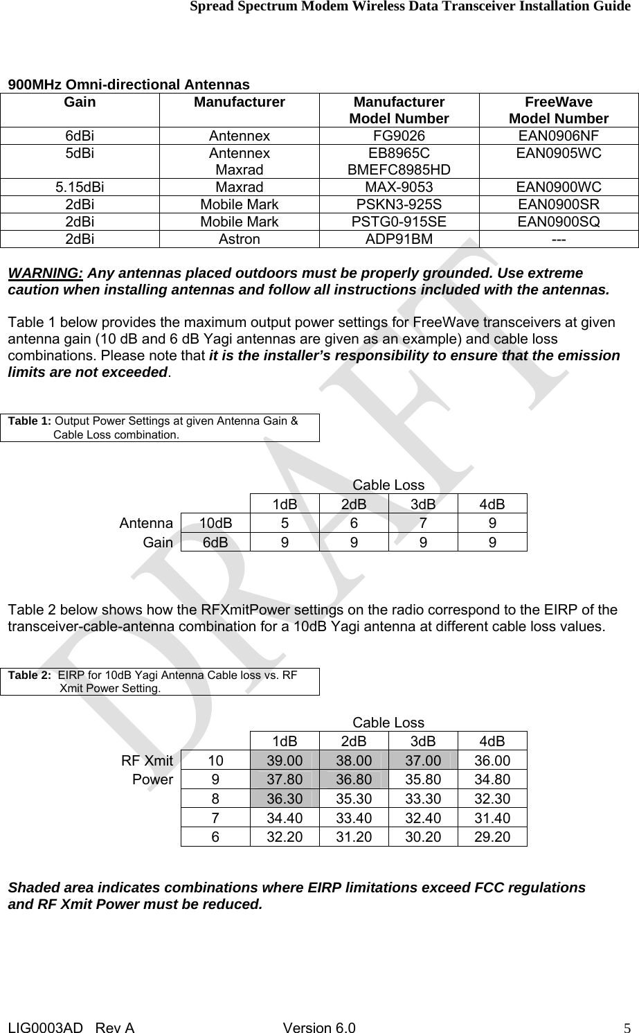
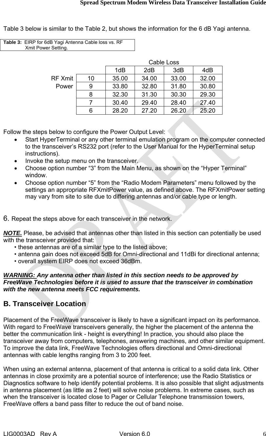
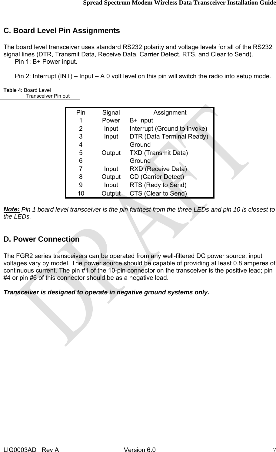
Updated users manual