Fujitsu Client Computing WB0043 Stylistic ST Series with AR5BXB6 WLAN & Bluetooth User Manual App I1 part 1

Fujitsu Limited Stylistic ST Series with AR5BXB6 WLAN & Bluetooth App I1 part 1

App I1 user manual part 1
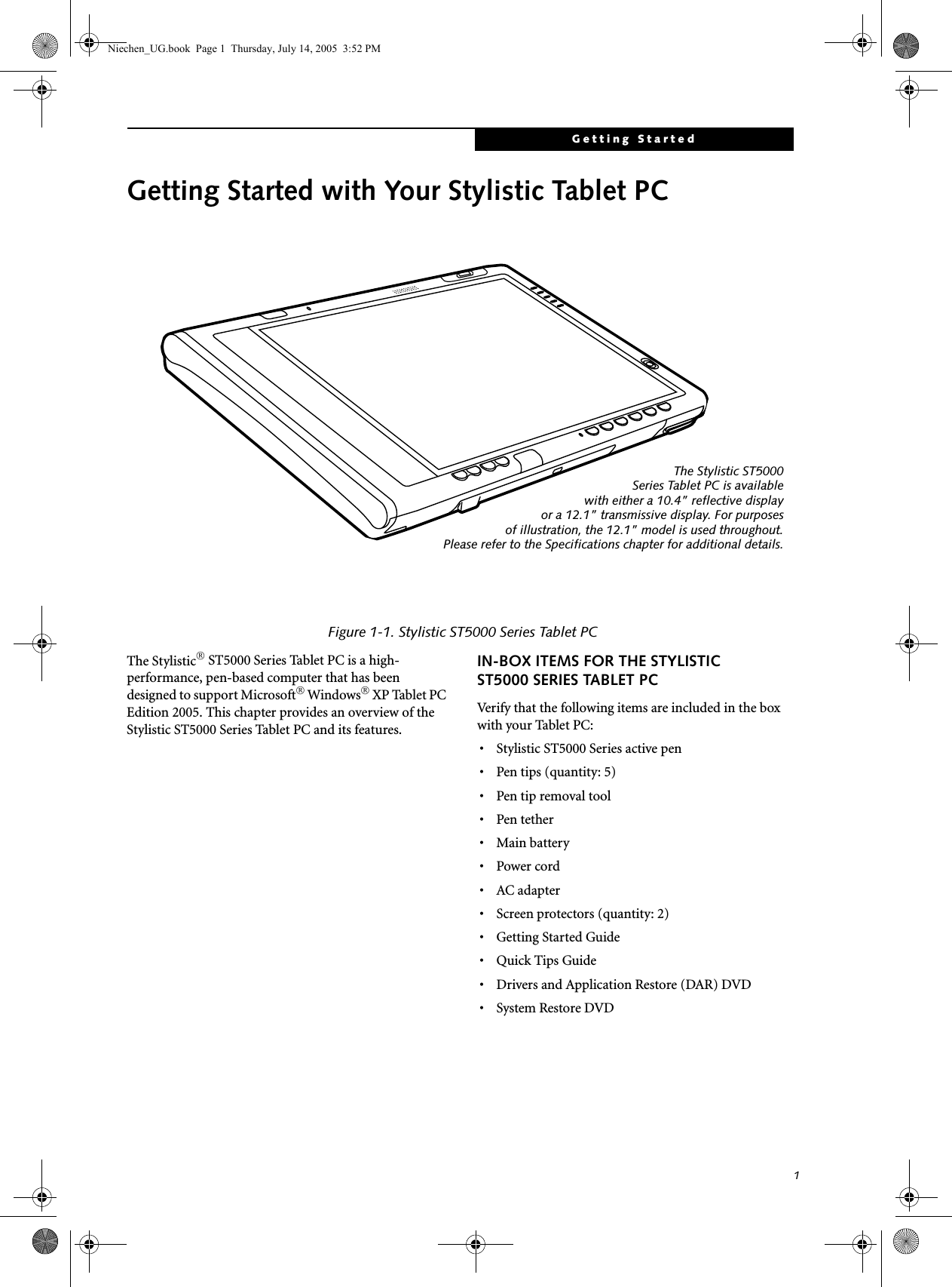
FCC ID: EJE-WB0043  (IC: 337J-WB0043)                                    Report No.  M060760_Cert_AR5BXB6_DTS_BT        EMC Technologies Pty Ltd – 57 Assembly Drive, Tullamarine VIC 3043 Australia www.emctech.com.au   EMC Technologies Report Number: M060760_Cert_AR5BXB6_DTS_BT     APPENDIX I1  FUJITSU NOTEBOOK USER MANUAL (part 1)
CopyrightCopyright and Trademark InformationFujitsu Computer Systems Corporation has made every effort to ensure the accuracy and completeness of this document. Because ongoing development efforts are made to continually improve the capabilities of our prod-ucts, however, the data contained herein represents Fujitsu design objectives and is provided for comparative purposes; actual results may vary based on a variety of factors. This product data does not constitute a warranty. Specifications are subject to change without knowledge.Fujitsu and the Fujitsu logo are registered trademarks of Fujitsu Limited; Stylistic is a registered trademark of Fujitsu Computer Systems Corporation.Microsoft and Windows are registered trademarks or trademarks of Microsoft Corporation in the United States and/or other countries. PCMCIA and CardBus are registered trademarks of the Personal Computer Memory Card International Associa-tion.Intel, Pentium, and SpeedStep are trademarks or regis-tered trademarks of Intel Corporation or its subsidiaries in the United States and other countries.Atheros is a registered trademark of Atheros Communications, Inc.Bluetooth and the Bluetooth logo are registered trade-marks of Bluetooth SIG, Inc.Memory Stick is a registered trademark of Sony Corpora-tion and/or its affiliatesWi-Fi is a trademark of the Wireless Ethernet Compati-bility Alliance (WECA).All other products are trademarks or registered trade-marks of their respective companies. Copyright 2005  Fujitsu Computer Systems Corporation. All rights reserved. No part of this publication may be copied, reproduced, or translated, without the prior written consent of Fujitsu Computer Systems Corporation. No part of this publication may be stored or transmitted in any electronic form without the prior consent of Fujitsu Computer Systems Corporation.B6FH-6891-01EN-00 Note: For more detailed information about the FCC rules and their applicability to the Stylistic ST5110 Series Tablet PC, refer to Chapter 5 of this document.WarningHandling the cord on this product will expose you to lead, a chemical known to the State of California to cause birth defects or other reproductive harm. Wash hands after handling.DECLARATION OF CONFORMITYaccording to FCC Part 15Responsible Party Name: Fujitsu Computer Systems CorporationAddress: 1250 E. Arques Avenue, MS 122Sunnyvale, CA 94085Telephone: 408-746-6000Declares that product: Model Series: Stylistic® ST5110 Tablet PCComplies with Part 15 of the FCC RulesThis device complies with Part 15 of the FCC rules. Operation is subject to the following two conditions: (1) This device may not cause harmful interference, and, (2) This device must accept any interference received, including interference that may cause undesired operation.Niechen_UG.book  Page i  Thursday, July 14, 2005  3:52 PM
Stylistic ST5000 Series Tablet PC - User’s GuideIMPORTANT SAFETY INSTRUCTIONS ■This unit requires an AC adapter to operate. Use only UL Listed Class 2 Adapters with an output rating of 16 VDC, with a current of 3.75A minimum.AC Adapter output polarity:■When using your notebook equipment, basic safety precautions should always be followed to reduce the risk of fire, electric shock and injury to persons, including the following:■Do not use this product near water for example, near a bathtub, washbowl, kitchen sink or laundry tub, in a wet basement or near a swimming pool.■Avoid using the modem during an electrical storm. There may be a remote risk of electric shock from lightning.■Do not use the modem to report a gas leak in the vicinity of the leak.■Use only the power cord and batteries indicated in this manual. Do not dispose of batteries in a fire. They may explode. Check with local codes for possible special disposal instructions.■To reduce the risk of fire, use only No. 26 AWG or larger UL Listed or CSA Certified Telecommunication Line CordSAVE THESE INSTRUCTIONSFor Authorized Repair Technicians OnlySystem Disposal+Danger of explosion if Lithium (clock) bat-tery is incorrectly replaced. Replace only with the same or equivalent type recom-mended by the manufacturer. Dispose of used batteries according to the manufac-turer’s instruction.For continued protection against risk of fire, replace only with the same type and rating fuse.Hg          LAMP(S) INSIDE THIS PRODUCT            CONTAIN MERCURY AND MUST          BE RECYCLED OR DISPOSED OF ACCORDING TO LOCAL, STATE, ORFEDERAL LAWS.Niechen_UG.book  Page ii  Thursday, July 14, 2005  3:52 PM
Table of ContentsTable of ContentsPREFACEAbout This Guide . . . . . . . . . . . . . . . . . . . . . . . . .  vFujitsu Contact Information . . . . . . . . . . . . . . . . .  vLimited Warranty Information . . . . . . . . . . . . . . .  v1GETTING STARTEDGetting Started with Your Tablet PCIn-box Items for the Stylistic ST5000 Series Tablet PC. . . . . . . . . . . . . . . . . . . .  1Optional Accessories  . . . . . . . . . . . . . . . . . . . . . .  2Stylistic Tablet PC Features. . . . . . . . . . . . . . . . . .  3Status Display. . . . . . . . . . . . . . . . . . . . . . . . . . . .  8Application Buttons . . . . . . . . . . . . . . . . . . . . . .  10Navigation Buttons. . . . . . . . . . . . . . . . . . . . . . .  12Tertiary Functions of Buttons . . . . . . . . . . . . . . .  13Security Functions of Application Buttons. . . . . .  14Setting up the Security Panel . . . . . . . . . . . . . . .  14Passwords  . . . . . . . . . . . . . . . . . . . . . . . . . . . . .  14Using Your Security Panel  . . . . . . . . . . . . . . . . .  15Precautions  . . . . . . . . . . . . . . . . . . . . . . . . . . . .  15Uninstalling the Security Panel Application . . . . .  15Connectors and Peripheral Interfaces . . . . . . . . .  172USING YOUR TABLET PCUsing the ST5000 Series Tablet PCSystem States. . . . . . . . . . . . . . . . . . . . . . . . . . .  21Powering Up the Tablet PC . . . . . . . . . . . . . . . .  22Shutting Down the System. . . . . . . . . . . . . . . . .  22Suspending System Operation . . . . . . . . . . . . . .  22Resuming System Operation  . . . . . . . . . . . . . . .  24Adjusting the Display Brightness. . . . . . . . . . . . .  24Using the Pen. . . . . . . . . . . . . . . . . . . . . . . . . . .  24Calibrating the Pen. . . . . . . . . . . . . . . . . . . . . . .  25Installing a Pen Tether . . . . . . . . . . . . . . . . . . . .  25Replacing the Pen Tip. . . . . . . . . . . . . . . . . . . . .  25Charging the Battery . . . . . . . . . . . . . . . . . . . . .  25Removing and Installing the Battery. . . . . . . . . .  26Tips for Conserving Battery Power . . . . . . . . . . .  26Modem Connection  . . . . . . . . . . . . . . . . . . . . .  27Memory Stick/SD Card Slot . . . . . . . . . . . . . . . .  27PC Card Slot  . . . . . . . . . . . . . . . . . . . . . . . . . . .  28Removing and Installing Memory Modules  . . . .  283CARING FOR YOUR TABLET PCCare and MaintenanceCaring for Your Tablet PC . . . . . . . . . . . . . . . . .  33Protecting the Display Screen. . . . . . . . . . . . . . .  33Storing the Tablet PC. . . . . . . . . . . . . . . . . . . . .  34Avoiding Overheating . . . . . . . . . . . . . . . . . . . .  34Cleaning the Display Screen. . . . . . . . . . . . . . . .  34Troubleshooting. . . . . . . . . . . . . . . . . . . . . . . . .  34Restoring the Pre-Installed Software  . . . . . . . . .  35Restoring the Factory Image  . . . . . . . . . . . . . . .  36Automatically Downloading Driver Updates. . . .  374SYSTEM SPECIFICATIONSST5000 Series Hardware SpecificationsProcessing Specifications . . . . . . . . . . . . . . . . . .  41Memory/Storage Specifications . . . . . . . . . . . . .  41Display Specifications. . . . . . . . . . . . . . . . . . . . .  41Physical Specifications . . . . . . . . . . . . . . . . . . . .  41Interface Specifications  . . . . . . . . . . . . . . . . . . .  41Power Specifications  . . . . . . . . . . . . . . . . . . . . .  42Environmental Specifications . . . . . . . . . . . . . . .  42Agency Approval Specifications . . . . . . . . . . . . .  42Additional Specifications  . . . . . . . . . . . . . . . . . .  42Regulatory InformationNotice . . . . . . . . . . . . . . . . . . . . . . . . . . . . . . . .  43Niechen_UG.book  Page i  Thursday, July 14, 2005  3:52 PM
Stylistic ST5000 Series Tablet PC User’s Guide APPENDIX A: WIRELESS LAN/BLUETOOTH USER’S GUIDEBefore Using the Wireless LANFor better communications. . . . . . . . . . . . . . . . .  49Stopping transmission  . . . . . . . . . . . . . . . . . . . .  50Starting Transmission . . . . . . . . . . . . . . . . . . . . .  50Connecting the WLANFlow of operations . . . . . . . . . . . . . . . . . . . . . . .  51Preparation for wireless LAN connection  . . . . . .  51Connection to the network  . . . . . . . . . . . . . . . .  53Other settingsSetting of power-saving function . . . . . . . . . . . .  57WLAN TroubleshootingTroubleshooting. . . . . . . . . . . . . . . . . . . . . . . . .  58Wireless LAN GlossaryGlossary . . . . . . . . . . . . . . . . . . . . . . . . . . . . . . .  60IP address informationAdditional Information . . . . . . . . . . . . . . . . . . . .  62SpecificationsSpecification. . . . . . . . . . . . . . . . . . . . . . . . . . . .  63Using the Bluetooth DeviceWhat is Bluetooth?. . . . . . . . . . . . . . . . . . . . . . .  64Where to find information about Bluetooth . . . .  64APPENDIX B: SECURITY DEVICE USER’S GUIDEFingerprint Sensor DeviceIntroducing the Fingerprint Sensor Device . . . . .  67Getting Started  . . . . . . . . . . . . . . . . . . . . . . . . .  67Installing OmniPass . . . . . . . . . . . . . . . . . . . . . .  67User Enrollment . . . . . . . . . . . . . . . . . . . . . . . . .  68Using OmniPass. . . . . . . . . . . . . . . . . . . . . . . . .  69Configuring OmniPass . . . . . . . . . . . . . . . . . . . .  71OmniPass Control Center  . . . . . . . . . . . . . . . . .  72Troubleshooting. . . . . . . . . . . . . . . . . . . . . . . . .  74Trusted Platform Module InstallationTPM Installation. . . . . . . . . . . . . . . . . . . . . . . . .  75IndexIndex . . . . . . . . . . . . . . . . . . . . . . . . . . . . . . . . .  77Niechen_UG.book  Page ii  Thursday, July 14, 2005  3:52 PM
PrefaceNiechen_UG.book  Page iii  Thursday, July 14, 2005  3:52 PM
Stylistic ST5000 Series Tablet PC User’s Guide – PrefaceNiechen_UG.book  Page iv  Thursday, July 14, 2005  3:52 PM
PrefacePrefaceABOUT THIS GUIDEThe Stylistic® ST5000 Series Tablet PC is a high-performance, pen-based computer that has been designed to support Microsoft®Windows® XP Tablet PC Edition.This manual explains how to operate your Fujitsu Stylistic ST5000 Series Tablet PC hardware and built-in system software. The Stylistic ST5000 Series Tablet PC is a completely self-contained unit with an active-matrix (TFT) color LCD display and an active digitizer. It has a powerful interface that enables it to support a variety of optional features. Conventions Used in the GuideKeyboard keys appear in brackets. Example: [Fn], [F1], [ESC], [ENTER] and [CTRL].Pages with additional information about a specific topic are cross-referenced within the text.Example: (See page xx.)On screen buttons or menu items appear in boldExample: Click OK to restart your Tablet PC.DOS commands you enter appear in Courier type. Example: Shut down the computer?FUJITSU CONTACT INFORMATIONService and SupportYou can contact Fujitsu Service and Support in the following ways:■Toll free: 1-800-8Fujitsu (1-800-838-5487)■E-mail: 8fujitsu@us.fujitsu.com■Web site: http://www.computers.us.fujitsu.com/supportBefore you place the call, you should have the following information ready so the customer support representative can provide you with the fastest possible solution:■Product name■Product configuration number■Product serial number■Purchase date■Conditions under which the problem occurred■Any error messages that have occurred■Type of device connected, if anyFujitsu OnlineYou can go directly to the online Fujitsu product catalog for your Stylistic Tablet PC by clicking on the Fujitsu Weblinks -> LifeBook Accessories web site link, located in the Windows Start -> All Programs menu.You can also reach Fujitsu Service and Support on-line by clicking on the Fujitsu Weblinks -> Fujitsu Service and Support Web site link, located in the Service and Support Software folder of the Windows Start -> All Programs menu..LIMITED WARRANTY INFORMATIONYour Stylistic ST5000 Series Tablet PC is backed by an International Limited Warranty. Check the service kit that came with your system for warranty terms and conditions.The information icon highlights information that will enhance your understanding of the subject material.The caution icon highlights information that is important to the safe operation of your computer, or to the integrity of your files. Please read all caution information carefully.The warning icon highlights information that can be hazardous to either you, your computer, or your files. Please read all warning information carefully.You must have an active internet connec-tion to use the online URL links.Niechen_UG.book  Page v  Thursday, July 14, 2005  3:52 PM
Stylistic ST5000 Series Tablet PC User’s Guide – PrefaceNiechen_UG.book  Page vi  Thursday, July 14, 2005  3:52 PM
1Getting Started with Your Tablet PCNiechen_UG.book  Page vii  Thursday, July 14, 2005  3:52 PM
Stylistic ST5000 Series Tablet PC User’s Guide – Section OneNiechen_UG.book  Page viii  Thursday, July 14, 2005  3:52 PM
1Getting StartedGetting Started with Your Stylistic Tablet PCFigure 1-1. Stylistic ST5000 Series Tablet PCThe Stylistic® ST5000 Series Tablet PC is a high-performance, pen-based computer that has been designed to support Microsoft® Windows® XP Tablet PC Edition 2005. This chapter provides an overview of the Stylistic ST5000 Series Tablet PC and its features.IN-BOX ITEMS FOR THE STYLISTIC ST5000 SERIES TABLET PCVerify that the following items are included in the box with your Tablet PC: • Stylistic ST5000 Series active pen• Pen tips (quantity: 5)•Pen tip removal tool•Pen tether• Main battery •Power cord•AC adapter• Screen protectors (quantity: 2)• Getting Started Guide• Quick Tips Guide• Drivers and Application Restore (DAR) DVD• System Restore DVDThe Stylistic ST5000Series Tablet PC is availablewith either a 10.4” reflective displayor a 12.1” transmissive display. For purposesof illustration, the 12.1” model is used throughout.Please refer to the Specifications chapter for additional details.Niechen_UG.book  Page 1  Thursday, July 14, 2005  3:52 PM
2Stylistic ST5000 Series Tablet PC User’s Guide – Section OneOPTIONAL ACCESSORIESThe following optional accessories can be used with the Stylistic ST5000 Series Tablet PC. Refer to the instructions provided with these accessories for details on their use.For the latest list of accessories available for your Tablet PC, be sure to frequently check the Fujitsu Web site at: www.shopfujitsu.com.Table 1-1.  Stylistic ST5000 Series Optional AccessoriesPeripheral/AccessoryDocking OptionsTablet PC Tablet Dock, with CD-ROM drive Universal Dock Mount Tablet PC Tablet Dock, with Combo DVD/CD-RW drive Folding Desk StandCharge-Only CradleCarrying CasesTablet PC Executive Leather Portfolio Case  Bump CaseTablet PC Nylon Attaché Case  Easel CaseHarsh Environment Case (HEC) Hand StrapMedia OptionsExternal USB Floppy Disk Drive  USB CD-ROM DriveExternal DVD/CD-ROM Combo DriveMemory256 MB SO DIMM, DDR2 400 MHz 128 MB Compact Flash Card512 MB SO DIMM, DDR2 400 MHz 256 MB Compact Flash Card1 GB SO DIMM, DDR2 400 MHz 128 MB Secure Digital Memory CardPower OptionsAC Adapter with US Cord Auto/Airline AdapterMain Battery Battery ChargerHigh-Capacity BatteryInput DevicesWireless Keyboard  USB Optical MouseWireless Keyboard with Touchpad Stylistic ST5000 Tablet PC Pen (2-pack)Logitech Wireless Keyboard and Mouse  Wireless Mouse with Scroll FunctionAdditional AccessoriesScreen Protectors (6-pack)  Compact Flash Card AdapterHEC Screen Protectors (2-pack) Notebook Guardian Lock4 in 1 PC Card Adapter (SD/MMC/Memory Stick/SmartMedia)Deluxe Pen TetherCharge-Only Cradle DC AdaptersNiechen_UG.book  Page 2  Thursday, July 14, 2005  3:52 PM
3Getting StartedSTYLISTIC TABLET PC FEATURESFeatures and controls that you use to operate the Stylistic ST5000 Series Tablet PC are outlined below and illustrated in Figures 1-1 through 1-6. Details on using these features and controls are provided later in this manual.Figure 1-2. Stylistic ST5000 Series Tablet PC Features (Front View)Front Features: 1•Infrared keyboard/mouse ports: The infrared ports are used for communicating with a proprietary infrared keyboard or mouse.† •Speaker: Allows you to listen to mono audio files.•Fingerprint Swipe Sensor*: The optional fingerprint swipe sensor allows you to start your system by swiping your finger over the sensor. •System status LEDs: Indicate the operational status of the Tablet PC and hard disk drive, the charge level of the battery, and the security panel.•Power On/Suspend/Resume button: Allows you to turn on, off, suspend, resume, hibernate or wake the Tablet PC in order to optimize battery life. •Application buttons: Allow you to quickly launch pre-defined applications, utilities, and security features by pressing a button.• Navigation buttons: The navigation buttons allow you to move: Page Up/Page Down, Tab Right/Tab Left, Cursor Up/Cursor Down, and Cursor Right/Cursor Left.• Built-in Microphones: The built-in microphone(s) allow you to input mono audio. Note that the 10.4” model has only one microphone.† These peripherals and accessories are sold separately.* The fingerprint swipe sensor is available only on the 12.1” model.Power On/Suspend/SystemStatusResume Button Built-in SpeakerNavigation ButtonsLEDsApplication/Security MicrophoneInfrared Keyboard/Mouse PortInfrared Keyboard/Mouse PortFingerprint Swipe Sensor* Built-in Microphone (12.1” model only)ButtonsNiechen_UG.book  Page 3  Thursday, July 14, 2005  3:52 PM
4Stylistic ST5000 Series Tablet PC User’s Guide – Section OneFigure 1-3. Stylistic ST5000 Series Tablet PC Features (Back View)Back Features: 1•System interface connector: Allows you to connect the optional Stylistic Tablet Dock.† •Removable battery: Can be removed and replaced with a charged battery.† •Battery release latch: Used to release the removable battery.•Tablet Dock latch point: Allows you to attach the system to an optional Tablet Dock.† •Memory module cover: Removable cover over the memory modules.•Thermal Suede: Several areas of the system back are covered with “thermal suede”. This material should not be removed. It is designed to minimize the heat that the user feels when the system has been operating for an extended period of time.Air Vents: The air vents assist in proper cooling of the syatem.•Wireless LAN module cover: Provides protection for the optional wireless LAN radio.• Wireless LAN/Bluetooth On/Off switch: For systems with the optional wireless LAN radio or Bluetooth device, this switch toggles the radio on or off. †These peripherals and accessories are sold separately.Battery MemoryBatterySystem InterfaceReleaseLatchModule CoverConnectorTablet DockLatch PointsThermal SuedeWireless LAN*On/Off SwitchWireless LAN Module CoverAir VentsTo protect your notebook from damage and to optimize system performance, be sure to keep all air all vents unobstructed, clean, and clear of debris. This may require periodic cleaning, depending upon the environment in which the system is used. Do not operate the notebook in areas where the air vents can be obstructed, such as in tight enclosures or on soft surfaces like a bed or cushion.Niechen_UG.book  Page 4  Thursday, July 14, 2005  3:52 PM
5Getting Started Figure 1-4. Stylistic ST5000 Series Tablet PC Features (Top View)Top Features: 1•Pen: The main input device that you use to execute programs and enter data. A pen holder is built into the Tablet PC to store the pen when not in use. •Pen Tether Point: The pen tether point is used to attach a pen tether to help prevent loss of the pen.•PC Card slot: Allows you to insert a Ty pe I or Type II PCMCIA Card† in the system.•PC Card Eject Button: The PC Card eject button is used to remove a PC Card from the PC Card slot.•Air flow vents: Provides secondary cooling for processor. •SD Card/Memory Stick Slot: The Secure Digital (SD) card/Memory Stick slot allows you to insert a flash memory card† for data storage. Flash memory cards allow you to transfer data to and from a variety of different digital devices.•IrDA/FIR port: Provides an infrared interface for communication with devices compliant with IrDA Standard Revision 1.1.•Smart Card Slot: The dedicated Smart Card slot allows you to insert a Smart Card† on which you can store such data as medical information or electronic “cash”. †These peripherals and accessories are sold separately.Pen HolderSmart Card SlotPC Card Eject ButtonAir flow ventsPC Card SlotSD Card/Memory Stick Slot  IrDA/FIR PortPen Tether PointTo protect your notebook from damage and to optimize system performance, be sure to keep all air all vents unobstructed, clean, and clear of debris. This may require periodic cleaning, depending upon the environment in which the system is used. Do not operate the notebook in areas where the air vents can be obstructed, such as in tight enclosures or on soft surfaces like a bed or cushion.Niechen_UG.book  Page 5  Thursday, July 14, 2005  3:52 PM
6Stylistic ST5000 Series Tablet PC User’s Guide – Section One Figure 1-5. Stylistic ST5000 Series Tablet PC Features (Left Side View)Left-Side Features: 1•USB 2.0 ports: Allow you to connect Universal Serial Bus-compliant devices (compliant with USB Standard Revision 2.0) to the Tablet PC. Additional USB ports are located on the optional Tablet Dock†.•Headphone Jack: Allows you to connect a set of stereo headphones†. •Microphone Jack: Allows you to connect an external microphone†. •IEEE 1394 Jack: Allows you to connect IEEE 1394 (Firewire) peripherals such as digital video cameras† or external hard drives† to your Tablet PC.•External Monitor Connector: The External Monitor connector allows you to connect an external VGA, XGA, or SVGA CRT monitor.•Modem jack: Allows you to connect a standard RJ-11 connector to the Tablet PC’s internal 56 Kbps modem. Note that the internal 56 Kbps modem module installed in the Stylistic ST5000 Series Tablet PC has actual maximum transfer rates of 53 Kbps (receive), 33.6 Kbps (send), and 14.4 Kbps (fax). Download rates are limited to 53 Kbps in the United States due to FCC restrictions.•LAN jack: Allows you to connect a standard RJ-45 connector to the Tablet PC’s internal local area network (LAN). •Lock slot: Allows you to attach a compatible security cable.† •DC input connector: Allows you to connect the AC adapter or auto adapter.† †These peripherals and accessories are sold separately. LAN Jack*Modem Jack*Lock SlotDC Input JackExternal Monitor Connector (behind cover)Latch PointUSB 2.0 Ports Headphone JackMicrophone JackIEEE 1394 JackNiechen_UG.book  Page 6  Thursday, July 14, 2005  3:52 PM
7Getting StartedFigure 1-6. Stylistic ST5000 Series Tablet PC Features (Right Side View)Right-Side Features: 1•Pen: The main pointing device that you use to execute programs and enter data. A pen holder is built into the Tablet PC to store the pen when not in use. •Infrared keyboard/mouse port: The infrared port wraps around the front and bottom of the display, and is used for communicating with an optional proprietary infrared keyboard or mouse†.•Wireless LAN location: The optional wireless LAN device is located inside of the system housing.†These peripherals and accessories are sold separately. Pen / Pen HolderInfrared Keyboard/Mouse PortLatch PointOptional Wireless LAN locationNiechen_UG.book  Page 7  Thursday, July 14, 2005  3:52 PM
8Stylistic ST5000 Series Tablet PC User’s Guide – Section OneSTATUS DISPLAYIcons appear under each of the system status LEDs in the status display indicating the status of system functions such as system power and battery charge level. The loca-tion of icons in the Status display is shown in Figure 1-7.Table 1-2. explains how the LEDs associated with the individual icons are displayed, and describes what the variations of that display indicate. (If an icon is not displayed, it indicates that the related system function is off or inactive.Figure 1-7.      Status Display Icons PowerCharge/DC InBatteryHDD AccessSecurityIn the following table, a “blinking” LED flashes at the rate of once per second; an LED that is “blinking, slow” flashes at the rate of one second on, five seconds off.Icon Mode/State LED State RemarksPower  • On State• Idle ModeGreen, continuous The system is powered on and ready for use.• Suspend-to-RAM Green, blinking The system has suspended and saved active settings to RAM.• Off State•Hibernate (Save-to-Disk)Off The system has suspended and saved settings and data to the hard disk drive. Charge/DC In• On State• Idle Mode• Suspend-to-RAM•Hibernate (Save-to-Disk) • Off StateAmber AC adapter and battery are available and system is charging.Green • AC adapter and battery are available and system is not charging (battery fully charged).• AC adapter is available but battery is not present.Amber, blinking AC adapter and battery are available and waiting to charge (battery is out of thermal range).Off AC adapter is not available.Niechen_UG.book  Page 8  Thursday, July 14, 2005  3:52 PM
9Getting StartedTable 1-2. System Status IndicatorsBattery • On State• Idle ModeGreen, continuous Battery charge is between 50%-100%Amber, continuous Battery charge is between 13%-49%Red, continuous Battery charge is between 0%-12%Red, blinking There is a battery error.• Suspend-to-RAM,without AC adapter• Suspend-to-RAM with AC adapterGreen, blinking slow Battery charge is between 50%-100%.Amber, blinking slow Battery charge is between 13%-49%.Red, blinking slow Battery charge is between 0%-12%.•Hibernate (Save-to-Disk), with AC adapter• Off StateOff Battery is not installed, or system is off or in Hibernate mode.•Hibernate (Save-to-Disk),without AC adapterIf battery is inserted during power off, LED blinks amber for 4 seconds to detect battery. Battery status is displayed for 5 seconds after that.HDD Access• On State (or   flashing)• Idle ModeGreen Displayed when hard disk drive is accessed. • Suspend-to-RAM•Hibernate (Save-to-Disk)• Off StateOff Hard disk drive is not being accessed.Security • On State Green, continuous (until password is entered)The Security Indicator lights (if a password was set) when the system resumes from Off or Standby modes. You must enter the password that was set in the Security Panel before your system will resume operation. (See Security Functions of Application Buttons on page 14 for more information.)In the following table, a “blinking” LED flashes at the rate of once per second; an LED that is “blinking, slow” flashes at the rate of one second on, five seconds off.Icon Mode/State LED State RemarksNiechen_UG.book  Page 9  Thursday, July 14, 2005  3:52 PM
10Stylistic ST5000 Series Tablet PC User’s Guide – Section OneAPPLICATION BUTTONSThe six application buttons are located on the upper right-hand side of a vertically-oriented system. (See figure 1-2 on page 3 for location). Five of the buttons have secondary functions. The secondary functions are acti-vated by pressing the Function (Fn) button while pressing the application button. The buttons also have separate tertiary functions that can be used while the system is booting up. For more information about the tertiary functions, refer to Table 1-5 on page 13. Ctl-Alt-Del is the only application button that can be used while the system is logging on or when the system is locked (i.e., when you have the Logon or Computer Locked window showing on your desktop). Button Icon and Name(Primary)Tablet Icon (Fn + Button)(Secondary)DescriptionCtl-Alt-DelButton SecurityButtonPressing the Ctl-Alt-Del button for approximately one second allows you to log on after boot or after resuming from power management.Security Button: All five buttons are used when implementing security functions. Four of the buttons are used to enter the password, and the fifth is used as an Enter button. See “Security Functions of Application Buttons” on page 14.EMail ButtonInternet ButtonWhen you press the EMail button, you automatically launch Microsoft Outlook Express, where you can read, create, and send emails. When you press the Fn + EMail buttons at the same time, you automatically launch the Web browser. The default page to which you go is the Fujitsu home page. If you would like to change your home page, go to the Control Panel-> Internet Options. Select the General tab and enter the starting address you would like to use. OrientationButtonDisplay Mode ButtonWhen you press the Orientation button, the system screen orientation changes from portrait (vertical) to landscape (horizontal) or from landscape to portrait. When you would like to use the Tablet PC as an eBook, for example, you would use the portrait orientation, when accessing spreadsheets, you would more typically use a landscape orientation.When you press the Fn + Orientation buttons at the same time*, the display output will switch between internal, external, and simultaneous display.Escape ButtonApplication A ButtonThe Escape application button acts the same way as an Escape key on a keyboard.When you press the Fn + Esc buttons at the same time*, they act to invoke a pre-determined application or generate a combination keystroke, as assigned in the Tablet Button Settings utility. (You can change the settings in Control Panel -> Tablet Button Settings). By default, pressing the Fn + Esc combination acts the same as if you had pressed Ctl + Esc on a keyboard: the Start menu is launched.Niechen_UG.book  Page 10  Thursday, July 14, 2005  3:52 PM
11Getting StartedTable 1-3. Application Buttons - Primary and Secondary Functions*   The Fn button has a handy “sticky” feature that allows you to press two buttons in immediate succession, rather than at exactly the same time. After pressing the Fn button, you have a short time (2 to 3 seconds) to press the second button. Enter Button Application B ButtonThe Enter application button acts the same way as an Enter key on a keyboard.Pressing the Fn + Ent buttons at the same time*, acts to invoke a pre-determined application or keystroke combination, as assigned in the Tablet Button Settings utility. (You can change the settings in Control Panel -> Tablet Button Settings).By default, pressing the Fn + Ent combination acts the same as if you had pressed Alt on a keyboard: it selects a main menu in the typical Windows application.Function ButtonFujitsu Menu UtilityThe Function button works in conjunction with the other application buttons to provide additional functionality for the buttons. Refer to specific details above.*Pressing the Fn button twice in succession (within the “sticky” time*), causes the Fujitsu menu to appear on your screen, allowing you to modify certain system settings.Button Icon and Name(Primary)Tablet Icon (Fn + Button)(Secondary)DescriptionNiechen_UG.book  Page 11  Thursday, July 14, 2005  3:52 PM
12Stylistic ST5000 Series Tablet PC User’s Guide – Section OneNAVIGATION BUTTONSThe two navigation buttons are located on the lower right-hand side of a vertically-oriented system. (See figure 1-2 on page 3 for location). Each of the buttons can be toggled by pressing either end of the button. The buttons have dual functions. The secondary func-tions are activated by pressing the Function (Fn) button while pressing the application button*. The buttons also have separate tertiary functions that can be used while the system is booting up. For more information about the tertiary functions, refer to Table 1-5 on page 13. *   The Fn button has a handy “sticky” feature that allows you to press two buttons in immediate succession, rather than at exactly the same time. After pressing the Fn button, you have a short time (2 to 3 seconds) to press the second button. Table 1-4. Navigation ButtonsCtl-Alt-Del is the only Application button that can be used while the system is logging on or when the system is locked (i.e., when you have the Logon or Computer Locked window showing on your desktop). Buttons/icons Purpose (when pressed alone)(“Primary” function)Purpose (when pressed with Fn button)(“Secondary” function)This button consists of Page Up and Page Down segments. When the Page Up portion is pressed, you will scroll up one page. When the Page Down portion is pressed, you will scroll down one page. When pressed with the Function (Fn) button*, the Up portion of this button allows you to tab right.When pressed with the Function (Fn) button*, the Down portion of this button allows you to tab left.This button consists of Up and Down segments. When the Up portion is pressed, the cursor will move up. When the Down portion is pressed, the cursor will move down. When pressed with the Function (Fn) button*, the Up portion of this button will move the cursor to the right.When pressed with the Function (Fn) button*, the Down portion of this button will move the cursor to the left.Niechen_UG.book  Page 12  Thursday, July 14, 2005  3:52 PM
13Getting StartedTERTIARY FUNCTIONS OF APPLICATION AND NAVIGATION BUTTONSWhile you are booting up your system, the Application Buttons and Navigation buttons can be used for entering and navigating through the Basic Input-Output System (BIOS), and for invoking the Advanced Options Menu, where you can enter different modes (such as Safe Mode).The BIOS is a program and a set of parameters that are stored in ROM, which tests and operates your Tablet PC from when you turn it on until it loads your installed operating system from disk. Information from the BIOS is transferred to the operating system to provide it with information on the configuration and status of the hard-ware.The system is booting up while the Fujitsu logo is displayed immediately after turning on the system. The table below indicates how the buttons act while the system is booting up and while you are in the BIOS.Table 1-5. Tertiary Functions of Application and Navigation ButtonsButtons/icons Purpose (when pressed while the system is booting up)Ctl-Alt-Del ButtonPressing the Ctl-Alt-Del button while the system is booting up takes you into BIOS setup. This is the same as if you had tapped [F2] on a keyboard.EMail ButtonPressing the EMail button while the system is booting up opens the Boot Options menu. This is the same as if you had tapped [F12] on a keyboard.Orientation ButtonPressing the Orientation button while the BIOS setup screen is open causes the selected item (if applicable) to change to the next item. Pressing this is the same as tapping the spacebar on a keyboard.Escape ButtonPressing the Esc button while the BIOS is open acts to escape from the BIOS. This is the same as if you had tapped [Esc] on a keyboard.Enter ButtonPressing the Ent button while the BIOS is open acts the same as the [Ent] button on a keyboard. Function ButtonPressing the Fn button while the system is displaying the operating system boot menu, opens the Advanced Operating System Options menu. This menu allows you to enter different operating system modes (such as Safe Mode). Pressing this button is the same as if you had tapped [F8] on a keyboard.Pressing the top half of the upper navigation button while the BIOS setup screen is open causes the cursor in the BIOS setup screen to move up. This is the same as if you had tapped Arrow Up on a keyboard. This feature is also functional in the operating system boot menu.Pressing the bottom half of the upper navigation button while the BIOS setup screen is open causes the cursor in the BIOS setup screen to move down. This is the same as if you had tapped Arrow Down on a keyboard. This feature is also functional in the operating system boot menu.Pressing the top half of the lower navigation button while the BIOS setup screen is open causes the cursor in the BIOS setup screen to move right. This is the same as if you had tapped Arrow Right on a keyboard.Pressing the bottom half of the lower navigation button while the BIOS setup screen is open causes the cursor in the BIOS setup screen to move left. This is the same as if you had tapped Arrow Left on a keyboard.Niechen_UG.book  Page 13  Thursday, July 14, 2005  3:52 PM
14Stylistic ST5000 Series Tablet PC User’s Guide – Section OneSECURITY FUNCTIONS OF APPLICATION BUTTONSFive buttons are used when implementing security functions. Four of the buttons are used to enter the password, and the fifth is used as an Enter button. Instructions for using the security feature follow the table.Table 1-6. Security Functions of Application ButtonsSETTING UP THE SECURITY PANELWhen you receive your Tablet PC, the security panel application is pre-installed without any passwords. The following sections provide detailed information on your security panel, how to set, change or remove passwords.Numbered ButtonsUse these buttons to enter your password.(Figure 1-6)Enter ButtonAfter entering the button strokes, push this button to enter the password into the Tablet PC. (Figure 1-6)PASSWORDSThe user and supervisor password may be set on this Tablet PC. A supervisor password is typically the same for all Tablet PC’s and notebooks in a work group, office, or company to allow for system management. Individual computers in a group environment should not use a common password. A password consists of one to five button strokes plus the enter button. A valid stroke consists of pushing one or up to four buttons simulta-neously. The following are valid button strokes: ■Pushing [4] by itself■Pushing [2] and [3] at the same time■Pushing [1], [2], and [4] at the same time■Pushing [1], [2], [3], and [4] at the same timeThe following are valid passwords. The numbers within braces ({  }) are button strokes using more than one button. ■{[2]+[3]}, [1], [Enter]■[4], [enter]■{[1]+[3]}, {[2]+[3]+[4]}, [1], [4], [2], [Enter]Setting PasswordsWhen shipped from the factory, no passwords are set. You have a choice of having no password or setting a supervisor and user password. You must set the super-visor password before the user password. Button Icons Security Icons Security PurposeCtl-Alt-Del ButtonSecurity Enter ButtonEMail Button1Security Button 1Orientation Button2Security Button 2Escape Button3Security Button 3Enter Button4Security Button 4■The purpose of supervisor password is to be able to bypass the user password in case the user password is forgotten. The supervisor password alone will not lock the system.■You must set the supervisor and user passwords for the security panel to work.Niechen_UG.book  Page 14  Thursday, July 14, 2005  3:52 PM
15Getting StartedSetting Supervisor PasswordYou must have set a supervisor password before setting any user passwords. The supervisor password can bypass the user password.1. Go to the Start menu.2. Click on Run.3. Type in:C:\Program Files\Fujitsu\Security Panel Application\Supervisor\ FJSECS.EXE, then press [Enter]4. Follow the on-screen instructions to set theSupervisor password.Setting User Password1  Go to the Start menu.2. Click on All Programs.3. Click on Security Panel Application -> Security Panel Application.4. Follow the on-screen instructions to set theuser password.USING YOUR SECURITY PANELThe security lock feature is in effect both when the system resumes from Off, Standby, or Hibernation state. You always need to push the Security Panel buttons to input the user password. Your system will not begin the boot sequence until you enter your supervisor/user password.From Off State1. Turn on your system.2. When the Security Indicator flashes, enter the pass-word and press Enter button.For example, if the password is 22222, first press Button 2 five times and press the Enter button. The Tablet PC will boot to normal operation.From Standby/Hibernation State1. Press your Suspend/Resume button.2. When the Security Indicator flashes, enter the pass-word and press Enter button.The Tablet PC should resume normal operation.Incorrect Password EntryIf an invalid supervisor or user password is entered three times in succession, the system will “beep” for about one minute. If a valid password is entered within a minute (while system beeps), the beeping will stop and the Tablet PC will resume normal operation. If no password is entered or an invalid password is entered while the system beeps, the system will return to its previous locked state (standby or off) and the Security Indicator will go off. To reactivate the Tablet PC after a password failure, you must press the Suspend/Resume button, then enter a correct password.PRECAUTIONSLow Battery OperationsIf your Tablet PC has a low battery, pushing the suspend/resume button does not unlock the Tablet PC. To resume normal operation, first attach a power supply to the system. Then you may unlock the Tablet PC.UNINSTALLING THE SECURITY PANEL APPLICATIONYou have two options when uninstalling the securitypanel application:■Remove passwords and uninstall the security panel application software. This will disable all security features.■Uninstall the security panel application with password still active. This will not allow any changes to the password. Uninstalling the Security Panel Application SoftwareRemove passwords when User wants no password protec-tion whatsoever and doesn’t want to give anybody the utility to set a password on their computer. In this case, if passwords (supervisor, user, or both) are set, the pass-words must first be cleared BEFORE removing the appli-cation. To clear passwords, follow same procedure in SETTING PASSWORD CODES except this time, select REMOVE, enter current password then click Next. When asked to confirm select Ye s .You may change or remove the supervisor or user password by repeating the steps defined above.Remember the user password you specified on the Security Panel Application. If you forget the password you will not be able to use your computer. The supervisor pass-word can override the user password.Niechen_UG.book  Page 15  Thursday, July 14, 2005  3:52 PM
16Stylistic ST5000 Series Tablet PC User’s Guide – Section OneRemoving Security Panel Application withPasswords Still ActiveUsing this feature will not allow any changes tothe password. User: 1. Go to Start -> Control Panel.2. Open Add or Remove Programs Properties in the Control Panel. 3. Select the Security Panel Application in the list, and click Change/Remove. 4.  When the Confirm File Deletion box appears,click Ye s .Supervisor:1. Go to Start -> Control Panel.2. Open Add or Remove Programs Properties in the Control Panel. 3. Select the Security Panel Application forSupervisor in the list, and click Change/Remove. 4. When the Confirm File Deletion box appears,click Ye s .Reinstalling the Security Panel ApplicationTo reinstall supervisor or user security application, you will need your Drivers and Applications CD. The Utilities\Security Panel Application folder contains two separate folders: Supervisor and User. The setup files for supervisor and user security applications are contained in those folders. 1. Go to the Utilities\Security Panel Application\ Supervisor folder on the CD and double-click the setup.exe file. The Installing Security Panel Applica-tion window will appear. Follow the instructions on the screen.2. Go to the Utilities\Security Panel Application\User folder on the CD and double-click the setup.exe file. The Installing Security Panel Application window will appear. Follow the instructions on the screen.Supervisor and user passwords can be set via Windows software using the FJSECS.exe and FJSECU.exe files, respectively. FJSECU.exe for the user password cannot run without first setting a supervisor password. You need to run FJSECS.exe first to set the supervisor pass-word. Follow instructions under Setting Passwords on page 14.If you forget both passwords, please contact Fujitsu Computer Systems Corporation Service and Support at 1-800-8Fujitsu (1-800-838-5487). Fujitsu Computer Systems Corporation charges a service fee for unlocking a password-restricted Tablet PC. When calling please have a valid credit card and provide proof of ownership. You will then be given instructions on where to ship your Tablet PC.Removing the applications does not remove the password. It simply removes the utility to change/add/remove passwords. To change your password you must reinstall the application.Niechen_UG.book  Page 16  Thursday, July 14, 2005  3:52 PM
17Getting StartedCONNECTORS AND PERIPHERAL INTERFACESConnectors and peripheral interfaces on the Stylistic ST5000 Series Tablet PC allow the connection of a variety of devices. Specific locations are illustrated in Figures 1-2 through 1-5.Table 1-7 provides a description of each peripheral connector on the Stylistic ST5000 Series Tablet PC. Each of the illustrated icons is either molded into or printed on the Tablet PC chassis. Connector/PeripheralTablet PC Icon PurposeDC input connectorConnect an external power source such as the AC adapter or auto/airline adapter. USB Port Connect Universal Serial Bus 2.0 compliant devices to the Tablet PC. PCMCIA Card slot      Insert a Type I or Type II PC Card.SD Card/Memory Stick slotInsert a Secure Digital (SD) Card or a Memory Stick.Microphone jackConnect an external microphone. The internal microphone is disabled when you plug in an external microphone. Headphone jackConnect stereo headphones or powered external speakers. The internal speaker is disabled when you plug in external headphones or powered speakers. IrDA/FIR port  An infrared transceiver built into the Tablet PC allows you to communicate with other devices that are compliant with the IrDA Standard Rev. 1.1. Effective range for infrared communication is about 3 feet, and within 15 degrees off center. A clear line-of-sight path must exist between the IrDA port on the Tablet PC and the IrDA transceiver on the other device.Modem Connect a telephone line to the optional internal modem using a standard RJ-11 telephone plug.Tablet Dock portConnect the Stylistic ST5000 Series Tablet Dock or other approved docking device. Refer to documentation accompanying the docking device for more information.Niechen_UG.book  Page 17  Thursday, July 14, 2005  3:52 PM
18Stylistic ST5000 Series Tablet PC User’s Guide – Section OneTable 1-7. Peripheral Connectors/InterfacesInfrared keyboard/mouse portAn infrared receiver built into the Tablet PC allows you to communicate with a Fujitsu wireless infrared keyboard or mouse. The keyboard infrared port works optimally when it is placed between 10 to 30 cm (approximately 4 in. to 12 in.) from the keyboard infrared port (which is located on the bottom edge of the Tablet PC). Ensure there is a clear line-of-sight path between the infrared receiver on the Tablet PC and the infrared transmitter on the keyboard or mouse. Note that an infrared keyboard or mouse works best when the system is in landscape orientation.Lock slot The security slot allows you to secure the Tablet PC using compatible locking devices.IEEE 1394 jack The IEEE 1394 jack allows you to connect IEEE 1394 (Firewire) devices such as digital video cameras and external hard drives to your Tablet PC.Suspend/Resume buttonThe Suspend/Resume/Power On button allows you to suspend Tablet PC activity without powering off, resume your Tablet PC from suspend mode, and power on the system when it has been shut down from Windows. Page Up/Page DownThe Page Up/Page Down button allows you to navigate quickly from page to page without scrolling.Local Area Network (LAN)The LAN (RJ-45) jack is used to connect the internal 10/100/1000* Base-T/Tx Ethernet to a Local Area Network (LAN) in your office or home, or broadband devices such as a cable modem, DSL, or satellite internet. *1000 Mbps, commonly referred to as Gigabit Ethernet.Battery Release LatchThe battery release latch allows you to remove the battery from your system for storage or replacement.Wireless LAN/Bluetooth On-Off SwitchThe wireless LAN/Bluetooth switch allows you to turn power to the optional wireless LAN or Bluetooth devices on and off.Fingerprint Swipe SensorThe optional fingerprint swipe sensor allows you to avoid having to enter a user name and password every time you want to log into the system. This icon indicates the direction in which you should swipe your finger.Connector/PeripheralTablet PC Icon PurposeNiechen_UG.book  Page 18  Thursday, July 14, 2005  3:52 PM
192Using YourStylistic Tablet PCNiechen_UG.book  Page 19  Thursday, July 14, 2005  3:52 PM
20Stylistic ST5000 Series Tablet PC User’s Guide – Section TwoNiechen_UG.book  Page 20  Thursday, July 14, 2005  3:52 PM
21Using Your Stylistic ST5000Using the Stylistic ST5000 Series Tablet PCThis chapter covers the fundamental concepts, basic system operation and use, and system functions of the Stylistic ST5000 Series Tablet PC. You should familiarize yourself with this information before you attempt to operate the system.SYSTEM STATESBefore you begin using the Stylistic ST5000 Series Tablet PC, review the different system states (or modes) that the system can use. Being familiar with these states will help you determine whether it is appropriate to turn on, resume, suspend, hibernate or shut down the system when you begin or end a session. System behavior for each system state is described briefly in the following, with each system state listed in decreasing order of power usage:•On state: The system is running and the display screen is on. •Idle state: Some system functions are regulated or turned off to conserve power. The display screen may be turned off. The system returns to the On state when pen activity or other input is detected. •Suspend-to-RAM mode (S3): System operation is suspended. Most system functions are turned off to conserve power. Power to memory is on, maintaining data in programs that were running before system operation was suspended. The system does not respond to the pen or other input when in Suspend-to-RAM mode. Refer to the “Resuming System Operation” section later in this chapter for information on returning the system to the On state.•Hibernate mode (Save-to-Disk) (S4): System operation is suspended. All system functions are turned off to conserve power. Active data in programs that were running before suspending system operation is stored on the hard disk drive. The system does not respond to the pen or other input. Refer to the “Resuming System Operation” section later in this chapter for information on returning the system to the On state.•Off state: All system functions are turned off to conserve power. The system does not respond to the pen or other input. The system boots at the next system power-on.Your system may be configured to enter some of these states automatically after a period of inactivity to conserve battery power. When you use the Stylistic ST5000 Series Tablet PC, you can change the current system state in a number of ways, depending on the system’s current state. To determine the current system state, observe the Power icon in the Status display. Table 2-1 on page 22 gives the different system states represented by the Power icon and describes how you can change the system state from the current state.Prior to using your system, be sure to fully charge the battery if you plan to run on battery power. Failure to do so may result in erratic performance. The system consumes the same amount of power whether it is in Hibernate (Save-to-Disk) mode or the Off state. Niechen_UG.book  Page 21  Thursday, July 14, 2005  3:52 PM
22Stylistic ST5000 Series Tablet PC User’s Guide – Section Two  Table 2-1   Changing System States*Information in Table 2-1 on page 22 is supplied to help you understand which system states your system can enter from the current system state. Refer to the procedures on starting the system, shutting down the system, suspending system operation, and resuming system operation given later in this chapter. †Your system may be configured to use either Suspend-to-RAM mode or Hibernate mode. POWERING UP THE TABLET PCFollow the procedure below to start the Stylistic ST5000 Series Tablet PC. Before you begin, confirm that the system is in the Off state. To do so, observe the Status display. If the Power icon is not visible in the Status display, the system is in Off state or in Hibernate (Save-to-Disk) mode and it is safe to perform this procedure. If the Power icon is visible (either blinking or on continu-ously), do not perform this procedure. See “System States” earlier in this chapter for details on modes repre-sented by the Power icon. 1. Ensure that the battery in your Tablet PC is sufficiently charged, or connect an external power source such as the AC adapter or auto adapter to your Tablet PC. 2. Press the Power On/Suspend/Resume button to start the system. After performing initialization, the system starts the operating system installed on the hard disk drive. Once the operating system is running, you can use the system.SHUTTING DOWN THE SYSTEMFollow these steps to shut down and turn off your system:1. If system operation has been suspended, resume system operation. See “Resuming System Opera-tion” later in this chapter for details.2. Save your work and close all running programs.3. Choose Shut Down from the Windows Start menu.4. Carry out the Shut Down command. The system is now in the Off state. SUSPENDING SYSTEM OPERATIONThe Tablet PC allows you to suspend the system opera-tion without closing programs or exiting the operating system. Use this feature to conserve battery power when a system shutdown is not practical or when the battery needs to be changed. Icon Appearance Current State To Change State*  Power icondisplayedcontinuouslyOn Stateor Idle StateTo enter the Off state, shut down the system using the Start menu on your system. To enter Suspend-to-RAM or Hibernate (Save-to-Disk)† state, suspend system operation using either a hardware or software suspend.Power icon blinking Suspend-to-RAM†To enter the On state, resume system operation by pressing the Suspend/Resume button. To enter the Off state, resume system by pressing the Suspend/Resume button, then shut down your system. Power icon notdisplayedOff State, or,Hibernate (Save-to-Disk†) To enter the On state, start your system, or resume system operation by pressing the Suspend/Resume button. If you have set your system to turn power off from the Power Options utility in the Control Panel, the following procedure will not be possible, since pressing the button shuts the system down rather than suspending it. To change your power options, go to Start -> Settings -> Control Panel -> Power Options.Niechen_UG.book  Page 22  Thursday, July 14, 2005  3:52 PM
23Using Your Stylistic ST5000To suspend system operation: 1. Press the Suspend/Resume button, or carry out the Standby command from your operating system or power management program. (If your system is configured to suspend operation using Hibernate (Save-to-Disk) mode, which is explained later in this procedure, a message is displayed while data is saved to your hard disk.) 2. The Power icon either flashes (Suspend-to-RAM) or is not displayed (Hibernate) when system operation is suspended, depending on how your system is configured. At this point, programs that were running are stopped, active data is saved, and the system enters one of two different low-power states, or suspend modes, as explained in the following paragraphs. 3. Observe the Power icon in the Status display to deter-mine which suspend mode your system is using.■Power icon is blinking: Suspend-to-RAM mode.In this mode, active data is saved by maintaining power to RAM while most other system components are powered off. The Battery Gauge icon in the Status display indicates the battery charge level. ■Power icon is not displayed: Hibernate (Save-to-Disk) mode. In this mode, active data is stored on the hard disk drive and power usage is reduced to the same level used in the Off state. When the system is in Hibernate mode, the Battery Gauge icon is not visible in the Status display. In this mode, there is no danger of losing data if battery power is lost. If you have successfully performed this procedure, system operation is now suspended. Refer to “Resuming System Operation” later in this chapter to resume system operation. Also, note the following with regard to suspending system operation: ■You can remove the battery while the system is in Suspend-to-RAM or Hibernate modes in order to install a charged battery. To prevent losing unsaved data, wait until system operation has suspended before you remove the battery. Note that after you remove the battery, you have approximately five minutes to replace it with a new battery or to plug in a power supply before the bridge battery is depleted.■Your system may be configured to suspend operation automatically after a period of inactivity. ■Your system may be configured to enter Hibernate mode automatically after a period of time in Suspend-to-RAM mode. ■The system uses a small amount of battery power when in Suspend-to-RAM mode. Eventually, the battery will become fully discharged. ■If the battery charge drops to a Low-Battery Warning level while the system is running, the system will beep periodically. If this occurs, suspend system operation, shut down the system, or attach an external power source, such as the AC adapter, to the Tablet PC. ■If the battery charge drops to a Critically Low level while the system is running, the system is forced into a Suspend-to-RAM or Hibernate mode. If this occurs, you must either install a charged battery, or connect an external power source such as the AC adapter before you can resume system operation. (If the charge drops to a Critically Low level while the system is in Suspend-to-RAM mode, the system stays in that mode until power is restored or totally dissipated.)■Suspending system operation interrupts data commu-nications; therefore, some programs may block the system from suspending to prevent an interruption. ■The suspend action of the Suspend/Resume button may be disabled to prevent accidental interruption. If this is the case, pressing the Suspend/Resume button will not suspend system operation as described here. (In this case, suspend mode can only be achieved using the system software). Contact your local help desk or reseller if your system configuration is not suitable.■If your system is equipped with a PC Card that allows you to connect to a wired or wireless network, you may be logged off the network after a period of inactivity while system operation is suspended. Contact your network administrator or help desk, or call Fujitsu Service and Support at 1-800-8Fujitsu (1-800-838-5487) for details on your network log-off parameters. If you are replacing the battery, wait until system operation is suspended and the power icon is flashing before you remove the battery. Failure to do so could result in loss of your unsaved data. (Note that if the Resume On LAN function is enabled in the BIOS setup, you should not remove the battery unless the system is shut down. When Resume ON LAN is enabled, the bridge battery is disabled in order to optimize battery life.) If you will not be using the system for an extended period, shut down the system rather than using Suspend-to-RAM mode. Niechen_UG.book  Page 23  Thursday, July 14, 2005  3:52 PM
24Stylistic ST5000 Series Tablet PC User’s Guide – Section TwoRESUMING SYSTEM OPERATION To resume operation from either Suspend-to-RAM or Hibernate modes, press the Suspend/Resume button.■From Suspend-to-RAM modeStatus lights indicate that the system state is changing. It may take up to a minute before the system returns to the On state and system operation resumes. Note that the display turns on shortly before the pen becomes active due to the power-up sequences observed by the system.■From Hibernate (Save-to-Disk) modeActive data is read from the hard disk drive, and the system returns to the On state after a short time.Use the system as you normally would once system oper-ation resumes. All programs resume at the point where execution stopped when system operation was suspended. ADJUSTING THE DISPLAY BRIGHTNESSThere are four ways to adjust your display’s brightness:■Click the Tablet icon in the system tray at the bottom right of the screen. (When the cursor is on top of the icon, a message stating “Change tablet and pen set-tings” is displayed.) When the Tablet and Pen Settings window appears, select the Display tab, and move the Screen Brightness slider to change the brightness.■Click Start -> Control Panel -> Tablet and Pen Set-tings. Select the Display tab, and move the Screen Brightness slider to change the brightness.■Click the Fujitsu Menu icon in the system tray at the bottom right of the screen. (When the cursor is on top of the icon, a message stating “Fujitsu Menu...” is dis-played.) Select Tablet and Pen Settings and select the Display tab. Move the Screen Brightness slider to change the brightness.■Press the Fn key twice to invoke the Fujitsu menu and select Tablet and Pen Settings. USING THE PENYou can use the Stylistic ST5000 Series pen to generate and create electronic “ink”, to select items, and to navi-gate through programs on the Tablet PC. Programs that support handwriting recognition also allow you to write characters directly on the screen with the pen. You can also use the pen as a drawing tool.Figure 2-1. Stylistic ST5000 Series Pen The screen reacts when the pen tip is approximately 1/8 inch (3-5mm) from the screen. The pen has three switches: a tip switch and a barrel button toggle switch with switches at both ends. When activated, the tip switch corresponds to the left mouse button, and the front toggle (closest to the pen tip) barrel button switch, when used in combination with the tip switch, corre-sponds to the right mouse button. The rear toggle of the barrel button switch acts as an electronic ink “eraser” when it is so configured in the Control Panel. Note that the erasing feature is application-dependent.Note that power to several system components must be restored before system operation resumes. Allow sufficient time for system operation to resume before attempting to use the system. If your system uses Hibernate mode, it will take longer to resume operation as compared to using Suspend-to-RAM mode. Time is needed to read data from the hard disk drive. Depending upon whether you are running your system on battery or AC power, the default screen brightness settings will be different. The screen brightness default for running on battery is lower than that on AC power in order to optimize battery life.The Stylistic ST5000 pen is a sophisticated, high-quality electronic instrument that can be damaged if used improperly. Treat the pen as you would any precision device. The following list contains guidelines for proper pen handling:• Do not gesture with the pen, use it as a pointer, or tap it on surfaces other than the Tablet PC screen.• Do not try to turn the thumb grip on the pen; it is designed for inserting and removing the pen from the pen holder and for attaching a pen tether.• Never store the pen with the tip bearing the weight of the pen (e.g., sitting tip down in a pencil cup). Storing the pen tip down could distort the internal mechanism over a period of time (especially in higher temperatures), causing the tip to act as if it is always depressed. To avoid damage, the pen should be stored in the pen holder when not in use.Pen Tether Attachment PointTip SwitchBarrel SwitchNiechen_UG.book  Page 24  Thursday, July 14, 2005  3:52 PM
25Using Your Stylistic ST5000 Here are some hints that may help you use the pen more effectively:• To activate the tip switch, tap or hold the pen tip against the screen.• To activate the barrel button switch, press and hold the end of the button you wish to use (front toggle is the right mouse button switch; the rear toggle acts as an electronic “eraser”.• To move the cursor, hold the pen tip within 1/8 inch (3 - 5mm) from the screen and move the pen.• To start a program, double-tap the pen tip (tap the pen tip twice rapidly) on the program icon as you would double-click a mouse.•To select an object, tap the pen tip on the object once. •To “double-click” an object, tap twice on the object quickly.•To move, or “drag”, an object on the screen, place the pen tip directly over the object, then as you hold the pen tip against the screen, move the pen.CALIBRATING THE PENFor information about calibrating your pen, refer to the literature that came with the operating system.INSTALLING A PEN TETHERTo prevent dropping or losing your pen, you should attach it to your system using the pen tether that is included with the system. To attach the pen tether to your Tablet PC, perform the following steps:1. Attach the end of the pen tether with the smaller loop to your pen. Do do so, push the end of the tether through the hole in the pen, then thread the opposite end of the tether through the loop. (See Figure 2-2.)Figure 2-2. Installing a Pen Tether2. Attach the end of the pen tether with the larger loop to the attachment point on your pen tablet. To do so, insert the end of the pen tether through the attach-ment point, then feed the pen through the large loop in the tether.REPLACING THE PEN TIPWith use, the pen tip may become worn or may pick up foreign particles that can scratch the screen. A damaged or worn tip may not move freely, causing unpredictable results when using the pen. If your pen exhibits these problems, you should replace the pen tip. To do so, use the pen tip removal tool included with your pen.Figure 2-3. Tip Removal ToolTo remove the tip, position the tip in the gap between the two ends of the tool. Pinch the tool together so the tip is firmly clasped, then pull it from the barrel. If the tip is worn or damaged, discard it.To replace the tip, retrieve one of the new tips that accompanied your pen. Insert the flat end of the tip into the barrel and push it in firmly until it is seated.If you need more tips, they can be ordered from the Fujitsu Web site at: us.fujitsu.com/computers.CHARGING THE BATTERYThe Stylistic ST5000 Series battery can be charged while it is installed in the Tablet PC. To d o  s o:  1. Connect a DC power source, such as the AC adapter, to the DC input connector on the Tablet PC. The DC Input icon appears in the Status display. If the battery • Ensure that a screen protector is installed on the Tablet PC screen before you use the pen. The warranty does not cover a scratched screen.•Use only the pen provided with your Tablet PC. Do not use substitutes that were not designed for the Stylistic ST5000 Series Tablet PC. Smaller loopLarger loopPen tether attachmentpointGapNiechen_UG.book  Page 25  Thursday, July 14, 2005  3:52 PM
26Stylistic ST5000 Series Tablet PC User’s Guide – Section Twocharge is below 90%, the battery begins charging and the Charging icon appears in the Status display. If the battery charge is 90% or higher when you connect DC power, the battery will not charge, preventing battery overcharging. 2. Look at the Battery Gauge icon in the Status display to determine the percent of charge in the battery. See “Status Display” in Chapter 1 of this manual for a description of the Battery Gauge icon.As long as DC power remains connected to the Tablet PC, the charging process continues until the battery charge reaches 100%. Also note the following with respect to charging the battery: • You can use the system, suspend system operation, or shut down and turn off the system without interrupting the charging process; however, using the system while the battery is charging will cause the battery to charge at a slower rate.• As noted in the procedure above, the system will not begin charging the battery if the battery charge level is 90% or higher when the system is initially connected to external DC power. (This prevents the battery from being overcharged.) • The battery uses Lithium ion battery cells which have no “memory effect.” You do not need to discharge the battery before you begin charging. REMOVING AND INSTALLING THE BATTERYThe battery can be removed from the Tablet PC and swapped with a charged battery. The battery can then be charged in an external charger if one is available. To remove the battery from the Tablet PC: 1. Choose one of the following: • If a charged battery is available, you can suspend system operation. A built-in “bridge” battery will maintain the system in Suspend-to-RAM mode for about 5 minutes while the battery is removed; this allows time for replacement with a charged battery.• If a charged battery is not available, save your work and close all running programs, then shut down the system or Hibernate (Save-to-Disk).• Plug in an external DC power source.2. Slide the battery release latch in the direction indicated. (See Figure 2-4 on page 26 for location). 3. Pull the battery away from the system, as shown in the illustration and remove the battery from the Tablet PC. If you are using an external battery charger, refer to the instructions provided with the battery charger. To install the battery:1. Orient the battery with the slides in the empty battery tray. Slide the battery into the tray and press it firmly until it is seated. When it is properly seated, the battery release latch should return to position and lock the battery.Figure 2-4. Removing the BatteryOnce the battery is installed, you can resume system operation or start and use your system normally. TIPS FOR CONSERVING BATTERY POWERYou can extend the charge life of your battery by conserving battery power. (Your results may vary depending on your application and how the system is configured.) Here are some suggestions to help you conserve battery power:• Use an external power source such as the AC adapter whenever the system is docked. • Suspend system operation if you know that you won’t be using the system for a while. • Shut down the system if you won’t be using the system for an extended period of time. • Switch the wireless LAN switch Off when wireless LAN functionality in not needed (applicable only for systems with optional wireless LAN).• Use power management (available on the desktop) to help you conserve power automatically. • Reduce the brightness of the LCD.• Battery life is dependent upon the operating system, power settings, and applications in use.Under Federal, state, or local law, it may be illegal to dispose of batteries by putting them in the trash. Be sure to dispose of batteries in accordance with local government regulations. Niechen_UG.book  Page 26  Thursday, July 14, 2005  3:52 PM
27Using Your Stylistic ST5000Operation of the Bridge Battery When installed in the Tablet PC, the battery provides power to some system components—even when the system is in the Off state. When the battery is removed, power is supplied to these components by a “bridge” battery that is built into the Tablet PC.The bridge battery is not designed for long-term opera-tion. To maintain the bridge battery properly, observe the following measures:• To prevent draining the bridge battery, always store the system with a charged battery installed. • If the bridge battery becomes drained, it takes approximately 8 hours for it to be fully recharged.•  The bridge battery charges when the AC Adapter is connected and the system is in On or Off states or Suspend mode. It charges from the battery only when the system is in the On state.MODEM CONNECTION The Stylistic ST5000 Series Tablet PC is designed to accept a standard RJ-11 telephone plug. Connect the plug to the modem jack located on the left-hand side of the Tablet PC (See Figure 1-5 on page 6 for location). The tele-phone plug can be inserted whether or not the Tablet PC has power applied.If you need assistance configuring the Stylistic ST5000 Series Tablet PC modem or LAN, contact your local help desk or reseller.MEMORY STICK/SD CARD SLOTYour Tablet PC supports Memory Stick and SD flash memory cards on which you can store and transfer data to and from a variety of digital devices. These cards use flash memory architecture, which means they don’t need a power source to retain data. Memory Stick is a flash memory technology developed by Sony Electronics. Memory Stick allows you to record, transfer and share digital content, such as digital pictures, movies, music, voice, and computer data and applica-tions.Secure Digital (SD) Cards are very similar to Memory Sticks, but they are shorter. Like the Memory Stick, SD Cards allow portable storage among a variety of devices, such as cell phones, GPS systems, digital cameras, and PDAs. SD Cards transfer data quickly, with low battery consumption. Like the memory stick, it uses flash memory architecture.Figure 2-5. Memory Stick and Secure Digital CardInserting Memory Stick/SD CardsMemory Sticks and SD Cards are inserted in the Memory Stick/SD Card slot (Figure 1-4). To insert a Memory Stick or SD Card, follow these steps: 1. See your Memory Stick or SD Card manual for instructions on the insertion of your card. Some cards may require that your system is off while inserting them.2. Make sure there is no card currently in the slot. If there is, see Removing a Memory Stick/SD Card.3. Insert your card into the slot with the product label facing up.4. Push the card firmly into the slot until it is seated in the connector. • The bridge battery function is disabled if Wake On LAN is enabled in the BIOS.• The system arrives with the bridge battery in a discharged state. Be sure to charge it sufficiently before relying upon it to support the system in the event of battery removal. The internal 56 Kbps LAN/modem module installed in the Stylistic ST5000 Series Tablet PC has actual maximum transfer rates of 53 Kbps (receive), 33.6 Kbps (send), and 14.4 Kbps (fax). Download rates are limited to 53 Kbps in the United States due to FCC restrictions.Note that MagicGate functions are not supported by this slot.■Inserting or removing a Memory Stick or SD Card during your system’s shut-down or bootup process may damage the card and/or your computer.■Do not insert a card into a slot if there is water or any other substance on the card as you may permanently damage the card, your Tablet PC, or both.Niechen_UG.book  Page 27  Thursday, July 14, 2005  3:52 PM
28Stylistic ST5000 Series Tablet PC User’s Guide – Section TwoRemoving A Memory Stick/SD CardTo remove a Memory Stick/SD Card, follow these steps:Push the Memory Stick or SD Card in until it unlatches. It will then eject from the slot for removalPC CARD SLOTThe Stylistic ST5000 Series Tablet PC Card slot allows you to insert a Type I or Type II PCMCIA Card. Inserting a PC CardTo insert a PC card, position the side with the arrow facing up (i.e., when looking at the tablet’s display side, the arrow on the card should be visible.) Slide the card into the PC Card slot, and press it firmly to ensure proper seating. (See Figure 2-6 for location)If you need assistance inserting a PC Card in the Stylistic ST5000 Series Tablet PC, contact your corporate help desk or reseller.Figure 2-6. Inserting a PC CardRemoving a PC CardTo remove a PC Card, first click the Safely Remove Hardware icon in the system tray in the bottom right-hand corner of the display. Select PC Card from the list, and click [Stop]. Press the PC Card eject button so that it pops out. Once the button has popped out, press it firmly to eject the card. (See Figure 2-7 for location)Figure 2-7. Removing a PC CardREMOVING AND INSTALLING MEMORY MODULESThere are two DIMM slots in your Tablet PC. 256 MB, 512 MB, and 1 GB modules are available, so you can install a combination of up to 2 GB in the system.Installing a Memory ModuleTo install a DIMM module in the Tablet PC: 1. Ensure that the Tablet PC is off. To do so, carry out the Shut Down command in the Start menu. (Do not attempt to remove or install a DIMM module when the system is in Suspend mode or running.) 2. Remove the two screws from the cover plate on the back of the Tablet PC and remove the cover plate as shown in Figure 2-8.Figure 2-8. Accessing the Memory Slot3. Insert the DIMM module in the socket at an angle and push it down until it locks into place as shown in Figure 2-9. Note that the DIMM module is keyed to prevent it from being inserted backwards.Figure 2-9. Installing a DIMM ModuleSee your Memory Stick or SD Card manual for specific instructions on the removal of your card. Some cards may require your computer to be in Suspend Mode or Off while removing them. DIMM replacement should be performed at a static-free workstation. Do not touch connector pins, circuit boards, or other circuit components on the drive or Tablet PC. Electrostatic discharge caused by doing so can damage sensitive components.Niechen_UG.book  Page 28  Thursday, July 14, 2005  3:52 PM
29Using Your Stylistic ST50004. Reinstall the cover and screws that you removed in step 2. 5. Confirm that the DIMM module is recognized by the system. To do so, run BIOS Setup. The size of the DIMM module should be displayed in the Info menu in BIOS Setup. The DIMM module is installed in the Tablet PC and you can now use the system. Removing a Memory ModuleTo remove a DIMM module: 1. Ensure that the Tablet PC is off. To do so, carry out the Shut Down command in the Start menu. (Do not attempt to remove or install a DIMM module when the system is in Suspend mode or running.) 2. Remove the screws from the cover plate on the back of the Tablet PC and remove the cover plate as shown in Figure 2-8.3. Spread the fingers on the socket that lock the DIMM module in place until the DIMM module is loose. Figure 2-10. Removing a DIMM Module4. Remove the DIMM module from the socket. The DIMM module is now removed from the Tablet PC. See "Installing a Memory Module" to install a new DIMM module. Niechen_UG.book  Page 29  Thursday, July 14, 2005  3:52 PM
30Stylistic ST5000 Series Tablet PC User’s Guide – Section TwoNiechen_UG.book  Page 30  Thursday, July 14, 2005  3:52 PM
313Care and MaintenanceNiechen_UG.book  Page 31  Thursday, July 14, 2005  3:52 PM
32Stylistic ST5000 Series Tablet PC User’s Guide – Section ThreeNiechen_UG.book  Page 32  Thursday, July 14, 2005  3:52 PM
33Care and MaintenanceCare and MaintenanceThis chapter gives you pointers on how to care for and maintain your Stylistic ST5000 Series Tablet PC. CARING FOR YOUR TABLET PCPlease note the following information regarding proper treatment of your Tablet PC:■Your Tablet PC is a durable but sensitive electronic device. Treat it with respect and care.■Make a habit of transporting the system in a suitable car-rying case.■Do not attempt to service the computer yourself. Always follow installation and operation instructions closely.■If you accidentally spill liquid on your Tablet PC:1. Turn it off.2. Position it so that the liquid can run out.3. Let it dry out for 24 hours, or longer if needed.4. If your Tablet PC will not boot up after it has dried out, call your support representative.■Do not use your Tablet PC in a wet environment (near a bathtub, swimming pool).■Always use the AC adapter and batteries that are approved for your system.■Avoid exposure to sand, dust and other environmental hazards.■Do not expose your Tablet PC to direct sunlight for long periods of time as excessive temperatures may damage your system.■Do not put heavy or sharp objects on the computer.■Do not carry your system in a bag or briefcase while it is running; doing so could result in overheating or hard disk drive problems.■If you are carrying your system in a briefcase, or any other carrying case, make sure that there are no objects in the case pressing on the display.■Do not drop your Tablet PC or touch the screen with any sharp objects. PROTECTING THE DISPLAY SCREEN The Stylistic ST5000 Series Tablet PC is designed to provide you with years of service. Using a screen protector will help ensure the screen remains as clear as possible. When installed, the screen protector becomes a durable, replaceable writing surface that protects the display screen from abrasion. To obtain additional screen protectors, use Fujitsu part number FPCSP08AP (6-pack) when ordering. Additional information about installation is included with the screen protectors. To install a new screen protector on your Tablet PC: 1. If a screen protector is already installed on the display screen, remove it before installing the new screen protector.The screen protector is held onto the display screen surface by a thin strip of adhesive around the edges. A notch in one corner of the screen protector allows you to slide your fingernail under the screen protector for easy removal. 2. Clean the display by wiping the screen gently using a soft cotton cloth dampened with isopropyl alcohol. Ensure that all residue has been removed from the screen before applying a new screen protector. Remove the protective coating from the adhesive side of the screen protector first, as shown in Figure 3-1..Figure 3-1. Removing the Protective Sheet3. Apply the screen protector to the display screen surface. When doing so, orient the screen protector with the adhesive side of the screen protector facing the display screen and the notched corner of the screen protector oriented as shown in Figure 3-2.During normal use of the Tablet PC, small particles from the environment can become embedded in the pen tip and scratch the screen. To prevent scratching the screen, ensure that a screen protector is installed before using your Tablet PC. The warranty does not cover a scratched screen. ■The Stylistic ST5000 Series Tablet PC is not waterproof. Do not pour liquids on the system or wash it with a heavily soaked cloth. ■Do not place items on the top of the dis-play, or damage may occur.Niechen_UG.book  Page 33  Thursday, July 14, 2005  3:52 PM
34Stylistic ST5000 Series Tablet PC User’s Guide – Section ThreeFigure 3-2. Installing the screen protector4. Apply pressure to the screen protector with your finger using a continuous wiping motion along the edges. The adhesive sets completely within 48 hours. To ensure a good seal between the screen protector and the display, do not lift the screen protector from the display once it has been applied. 5. Remove the protective plastic cover from the face of the screen protector, as shown in Figure 3-3.Figure 3-3. Removing the protective cover6. Clean any residue left behind by the protective coating from the exposed surface of the screen protector by wiping gently with a soft cotton cloth dampened with isopropyl alcohol. Wipe the screen protector with a soft dry cloth to remove any low-tack adhesive; this will help prevent the pen tip from squeaking.STORING THE TABLET PCStore the Stylistic ST5000 Series Tablet PC in the Off state with a fully charged battery installed. You can store the Tablet PC in the Off state for about 30 days with a fully charged battery installed. After this period, the battery should be recharged or replaced with a charged battery. If you intend to store the Tablet PC for a longer period of time, the small battery that maintains system time may need to be replaced. Replacement of the clock battery should only be performed by authorized technicians. AVOIDING OVERHEATINGThe Tablet PC monitors its internal temperature. As the internal temperature approaches the tolerable limits of heat-sensitive components, system functions are auto-matically limited or turned off to prevent damage. To protect your notebook from damage and to optimize performance, keep all air all vents unobstructed, clean, and clear of debris. This may require periodic cleaning, depending upon the system environment. Do not operate the notebook in areas where the air vents can be obstructed, such as in tight enclosures or on soft surfaces like a bed or cushion.CLEANING THE DISPLAY SCREENTo clean the Tablet PC display screen, wipe the screen surface gently using a soft cotton cloth slightly damp-ened with water or isopropyl alcohol. TROUBLESHOOTINGSolutions to some common problems are described in the following sections. If you are experiencing a problem with your Tablet PC that you cannot solve by taking the actions described, contact your local help desk or reseller, or call Fujitsu Service and Support at 1-800-8Fujitsu (1-800-838-5487) for further assistance. System Will Not Resume OperationIf the system will not resume operation after system operation has been suspended, check the following: • The battery may either be defective, or discharged to a critically low level. When the battery reaches a critically low level, the system is forced into Suspend-to-RAM mode to avoid a total system power failure. To correct this problem, either connect an external power supply (such as the AC adapter), or install a charged battery in the Tablet PC. • The system may be at the critical thermal limit. To avoid damage to heat-sensitive components, the system enters Suspend-to-RAM mode when it gets too hot. System operation cannot be resumed until the Tablet PC cools off to a tolerable temperature. Move the Tablet PC to a cooler location. Do not expose your Tablet PC to direct sunlight for extended periods of time. High  temperatures could damage your tablet.The Tablet PC is not waterproof. Do not pour liquids on the Tablet PC or wash it with a heavily soaked cloth. Niechen_UG.book  Page 34  Thursday, July 14, 2005  3:52 PM
35Care and MaintenanceDisplay Screen Blank or Difficult to ReadIf the display screen on your Tablet PC appears blank or is unreadable, confirm that the system is running (the Power icon is displayed continuously on the Status display), and check the following: • The system brightness may be set too low, causing the screen to appear too dark. To change system brightness, press the Fn button twice to open the Fujitsu menu. Brightness can be adjusted from the menu.• The video timeout may have expired. Tap on the display screen to reactivate the display. Note that this is a normal, power-saving feature. Cursor Is Not Tracking PenIf the cursor on the screen appears to be misaligned with the pen or is not accurately tracking the pen, calibrate the pen. See “Calibrating the Pen” on page 25 for more infor-mation. Infrared Data Transfer Is Not WorkingIf you are experiencing problems transferring data over the system’s infrared interface, note the following:• Can the IrDA port on the Tablet PC “see” the IrDA port on the other device? A direct line-of-sight path must exist between the IrDA port on the Tablet PC and the IrDA port on the other device. • The distance between the two devices must not be more than 3 feet.• The viewing angle from the IrDA port on the Tablet PC must not be more than 15 degrees from a center line between the IrDA port on the Tablet PC and the IrDA port on the other device. • The device with which you are trying to communicate must be compliant with the IrDA Standard Revision 1.1 (or 1.0). • It may be necessary for both computers to be using the same network connection protocols.Tablet PC is Not Responding to the PenIf the Tablet PC does not respond to the pen, connect an external keyboard to the system to see if it responds to keyboard commands. If the system doesn’t respond to a keyboard, the application or system may have crashed, and it may be necessary to reboot the system. If the system responds to a keyboard but not to a pen, contact your local help desk or reseller, or call Fujitsu Service and Support at 1-800-8Fujitsu (1-800-838-5487) for further assistance.Speaker/Headphone Volume Too LowIf the audio volume on your Tablet PC speaker or external headphones is too low, check the following: • Ensure the speaker (or headphone output if using headphones) is enabled. To do so, open the Control Panel and double-click on the Sounds and Audio Devices icon. Select the proper tab, and increase the volume using the slider bar. (If you aren’t getting any sound, uncheck the Mute box if it is checked.) • Press the Fn button twice to open the Fujitsu menu. Volume can be adjusted from the menu.• Ensure the mute box in the system volume control (accessible from the system tray) is not set.• Ensure any volume control in your audio software is set to an audible level. Configuring Peripheral InterfacesCertain peripheral devices can be disabled during the BIOS Setup. If the peripheral interface you want to use does not appear to be working with your peripheral device, ensure that it is enabled in the BIOS. Contact your local help desk or reseller, or call Fujitsu Service and Support at 1-800-8Fujitsu (1-800-838-5487) if you need assistance using BIOS Setup.RESTORING THE PRE-INSTALLED SOFTWAREThe Drivers and Applications Restore (DAR) DVD contains sets of device drivers and Fujitsu utilities (in specific directories) that are unique to your computer configuration for use as documented below.Re-Installing Individual Drivers and Applications The Drivers and Applications CD can be used to selectively re-install drivers and/or applications that may have been un-installed or corrupted. To re-install drivers and/or applications:1. Boot up the system and insert the DAR CD after Windows has started. A Fujitsu Installer screen is displayed after the CD is inserted.2. After reading the License Agreement, click [I agree].If you have access to the internet, visit the Fujitsu Support web site at: http://www.computers.us.fujitsu.com/support to check for the most current information, drivers and hints on how to perform recovery and system updates.There may be certain free third-party applications pre-installed on your system that are not on the DAR CD. The latest versions of the applications can be downloaded from the third-party’s website.Niechen_UG.book  Page 35  Thursday, July 14, 2005  3:52 PM
36Stylistic ST5000 Series Tablet PC User’s Guide – Section Three3. A window will appear containing a list of applica-tions, drivers, and utilities that you can install from the Drivers and Applications CD.4. In the list, check off all the components you want to install. If you want to install all components, click [Select All]. Clicking [Select All] will select all of the blue-coded components; you must select grey and green components separately.5. Once you have selected the components you wish to install, click [Install Selected Subsystems]; the components will be installed.6. After the components are installed, click [OK], then click [Yes] when asked if you want to reboot the system. RESTORING THE FACTORY IMAGEThe Restore Disc that came with your system contains two utilities:■The Recovery utility allows you to restore the original contents of the C: drive.■The Hard Disk Data Delete utility on this disc is used to delete all data on your hard disk and prevent it from being reused. Do not use the Hard Disk Data Delete utility unless you are absolutely certain that you want to erase your entire hard disk, including all partitions.BOOT Priority ChangeBefore restoring an image, you must first verify that your system is set up to boot from the DVD drive. To verify/change the boot-up priority (rather than booting-up from the hard drive or an external floppy disk drive), perform the following steps:1. Start your system and press the [F2] key when the Fujitsu logo appears. You will enter the BIOS Setup Utility.2. Using the arrow keys, go to the Boot menu.3. Arrow down to the Boot Device Priority submenu. Press [Enter].4. If “Optical Media Drive” or “CD-ROM Drive” is not at the top of the list, arrow down to the drive in the list, and press the space bar (or the + key) to move it to the top of the list. (The system attempts to boot from the devices in the order in which they are listed.). Note that the BIOS for some systems will indicate “CD-ROM Drive”, even when a DVD drive is connected.5. If you have an external DVD drive connected, proceed to the next step; otherwise, proceed to step 7.6. If you have an external DVD drive connected:• Select the Advanced menu in the BIOS window.• Scroll down to the USB Features submenu and press the Enter key to open it.• If Legacy USB Support is disabled, press the space bar to enable it.• Scroll down to SCSI SubClass Support and press the space bar to enable it. 7. Press [F10], then click on [Yes] to exit the BIOS Setup Utility and return to the boot process.After you have changed the boot priority, you can restore a backup image when you are booting up.Procedure1. Turn on the power to your system.2. Ensure that you have a device that can read DVDs either installed in your system or attached exter-nally to it.3. Insert the Restore Disc into the drive tray.4. Reboot your system.5. After the system reboots, follow the instructions that appear to either restore your system image or erase all data from your hard disk.The components listed are color-coded in terms of their install status. Blue indicates that the component can be installed. Green indicates that the component needs to be installed separately. Grey indicates a component that is already installed; grey items can be reinstalled, but prior to installation you will receive a reminder that the component is already installed. The Restore Disc only restores the primary hard disk drive. If you have an optional second hard disk drive installed, it will not be restored using these utilities.• The use of this disc requires that you have a device capable of reading DVDs attached to your system. If you do not have a built-in DVD player, you will need to attach an external player. For more information on available external devices, visit our Web site at: us.fujitsu.com/computers. • This disc can only be used with the system with which it was purchased.Niechen_UG.book  Page 36  Thursday, July 14, 2005  3:52 PM
37Care and MaintenanceAUTOMATICALLY DOWNLOADING DRIVER UPDATESYour system has a convenient tool called the Fujitsu Driver Update (FDU) utility. With FDU, you can choose to automatically or manually go to the Fujitsu site to check for new updates for your system.The FDU icon  should appear in the system tray at the bottom right of your screen (roll the cursor over the icons to find the correct one). If the FDU icon does not appear in the system tray, it can be started by going to [Start] -> All Programs, and clicking on Fujitsu Driver Update; this will create the icon automatically.To invoke the FDU menu, right-click on the FDU icon. The menu contains the following items:■Check for updates nowAllows for manual driver update search. The first time it is used, you are prompted to agree to a user agree-ment. After clicking on the icon, the FDU automati-cally connects with the Fujitsu site to check for updates and downloads them. While downloading, the icon has a red bar through it, indicating that it cannot be used while the download is in process. When the update is complete, a message appears informing you of the fact.■Enable Automatic Update NotificationsAutomatically searches for new updates on a regular basis (approximately every 3 days).■Show update historyBrings up a screen that displays a history of updates that have been made via the FDU.■About Fujitsu Driver UpdateDisplays the FDU version number and copyright information■Fujitsu Driver Update ReadmeDisplays the FDU readme.Niechen_UG.book  Page 37  Thursday, July 14, 2005  3:52 PM
38Stylistic ST5000 Series Tablet PC User’s Guide – Section ThreeNiechen_UG.book  Page 38  Thursday, July 14, 2005  3:52 PM

Navigation menu