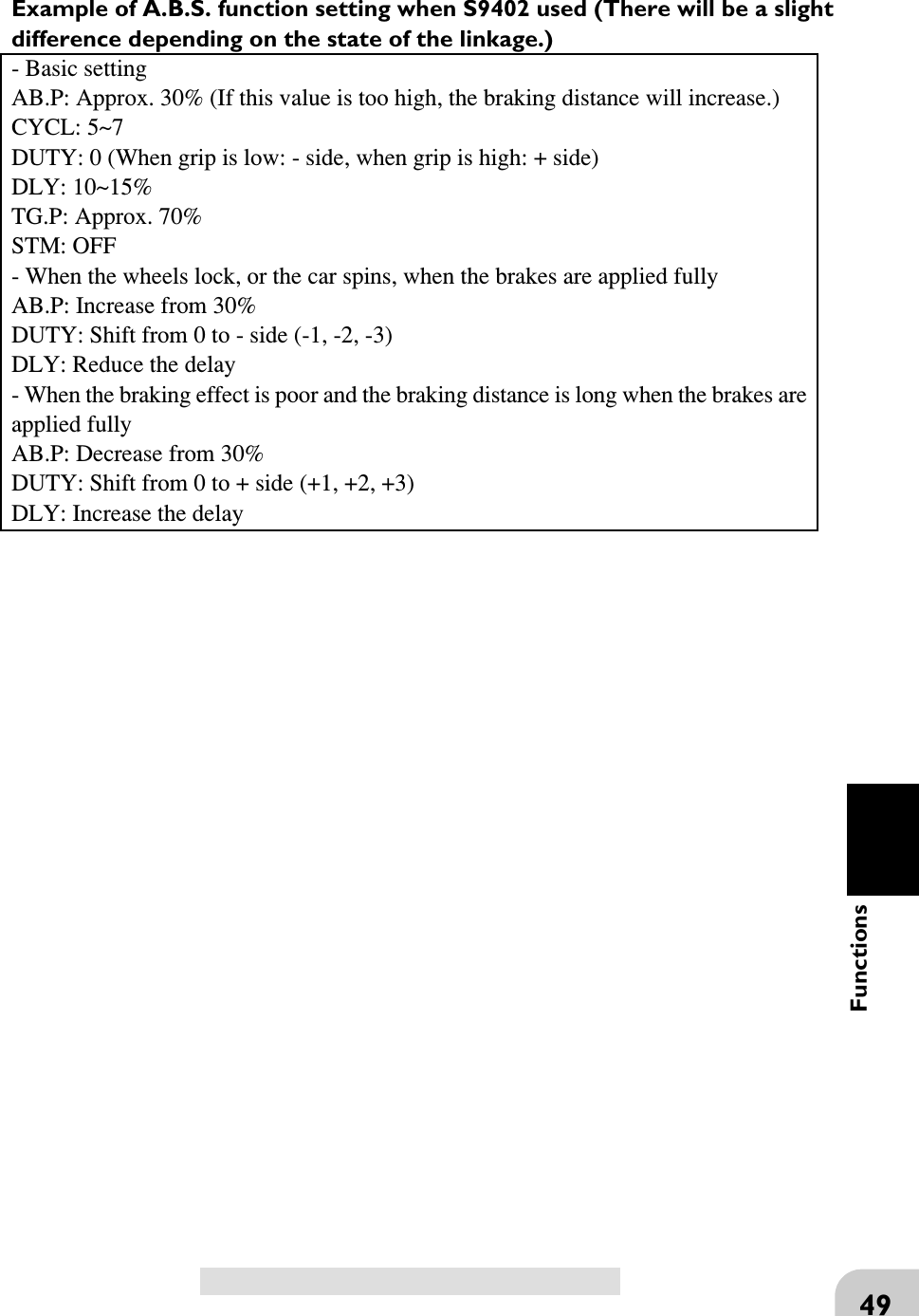
Futaba FP-PK-FM-75B Radio Control Transmitter User Manual I
Futaba Corporation Radio Control Transmitter I
UserManual.wiki
>
Futaba
>
FP-PK-FM-75B User Manual
>
User Manual I
Contents
1.
User Manual I
2.
User Manual II
User Manual I
Navigation menu
Upload a User Manual
Namespaces
Wiki Guide
HTML
PDF
Info
Views
User Manual
Discussion / Help
Navigation
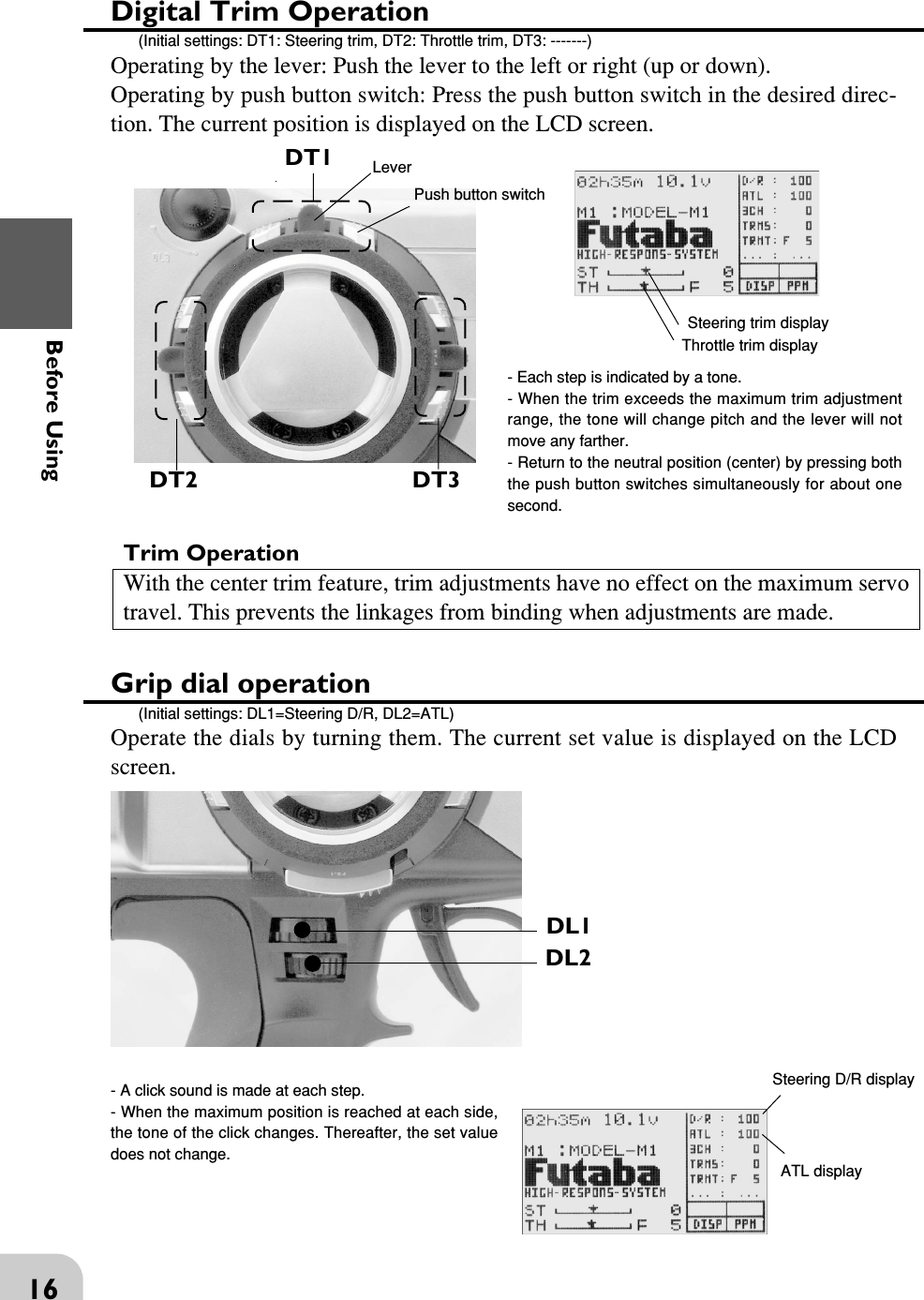
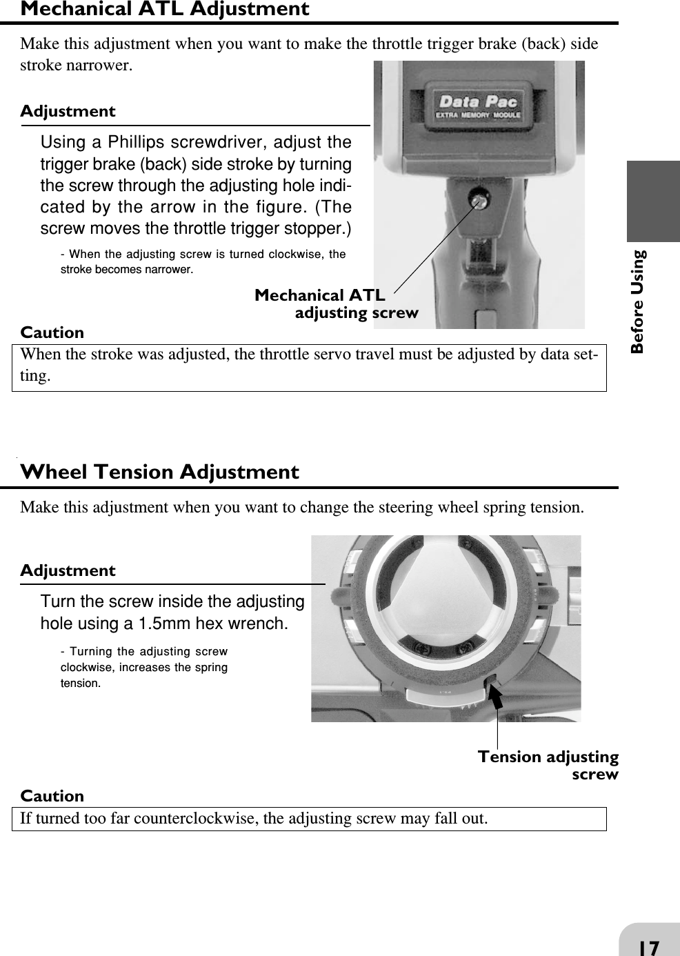
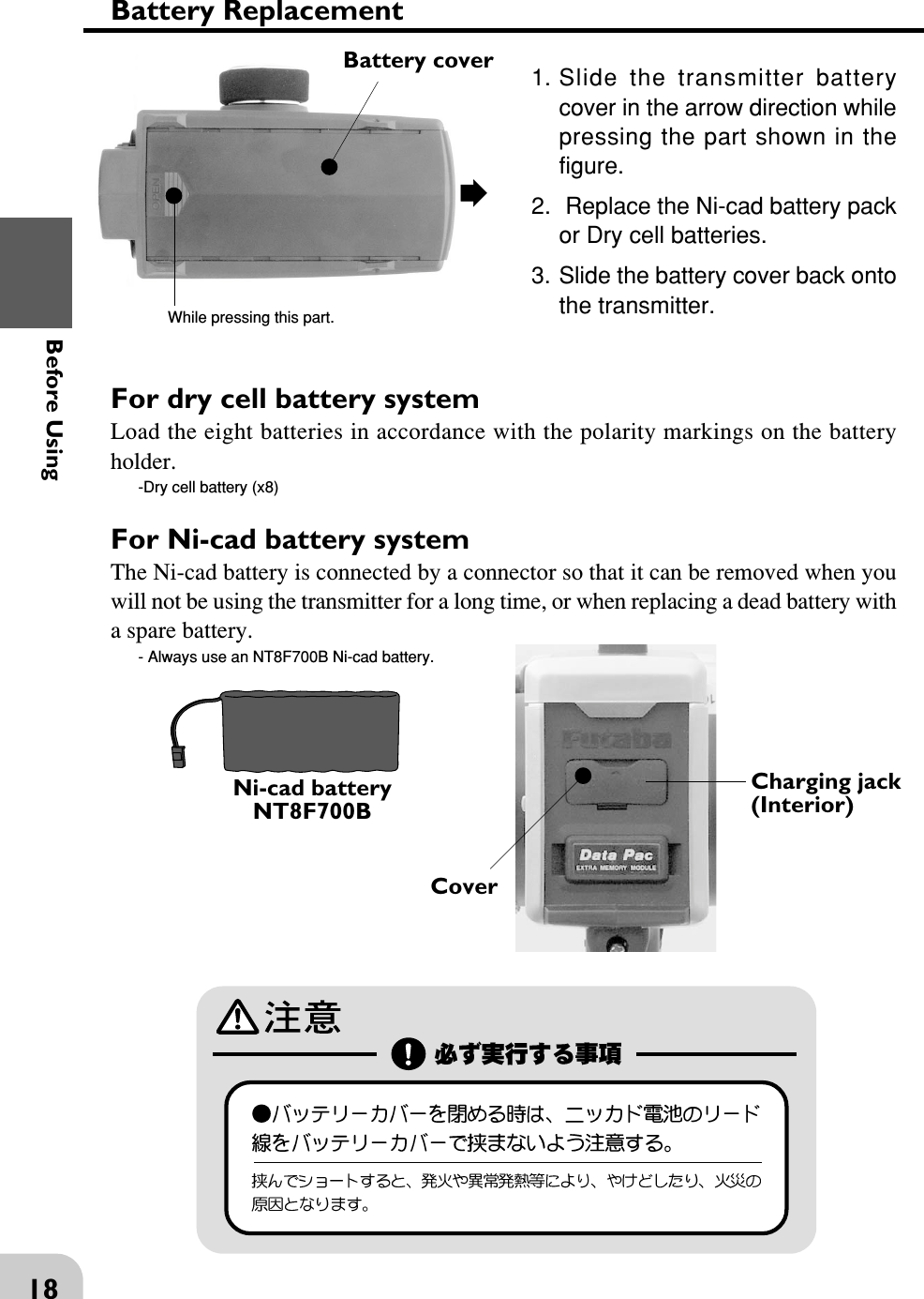
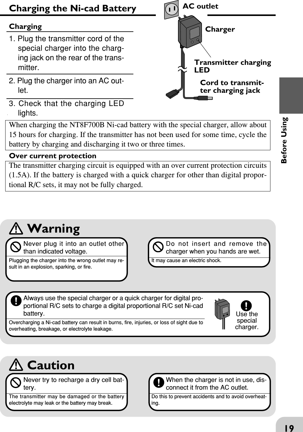
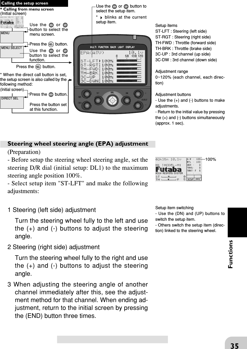
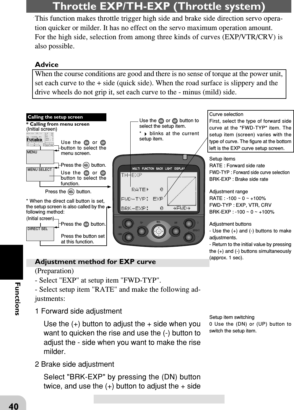
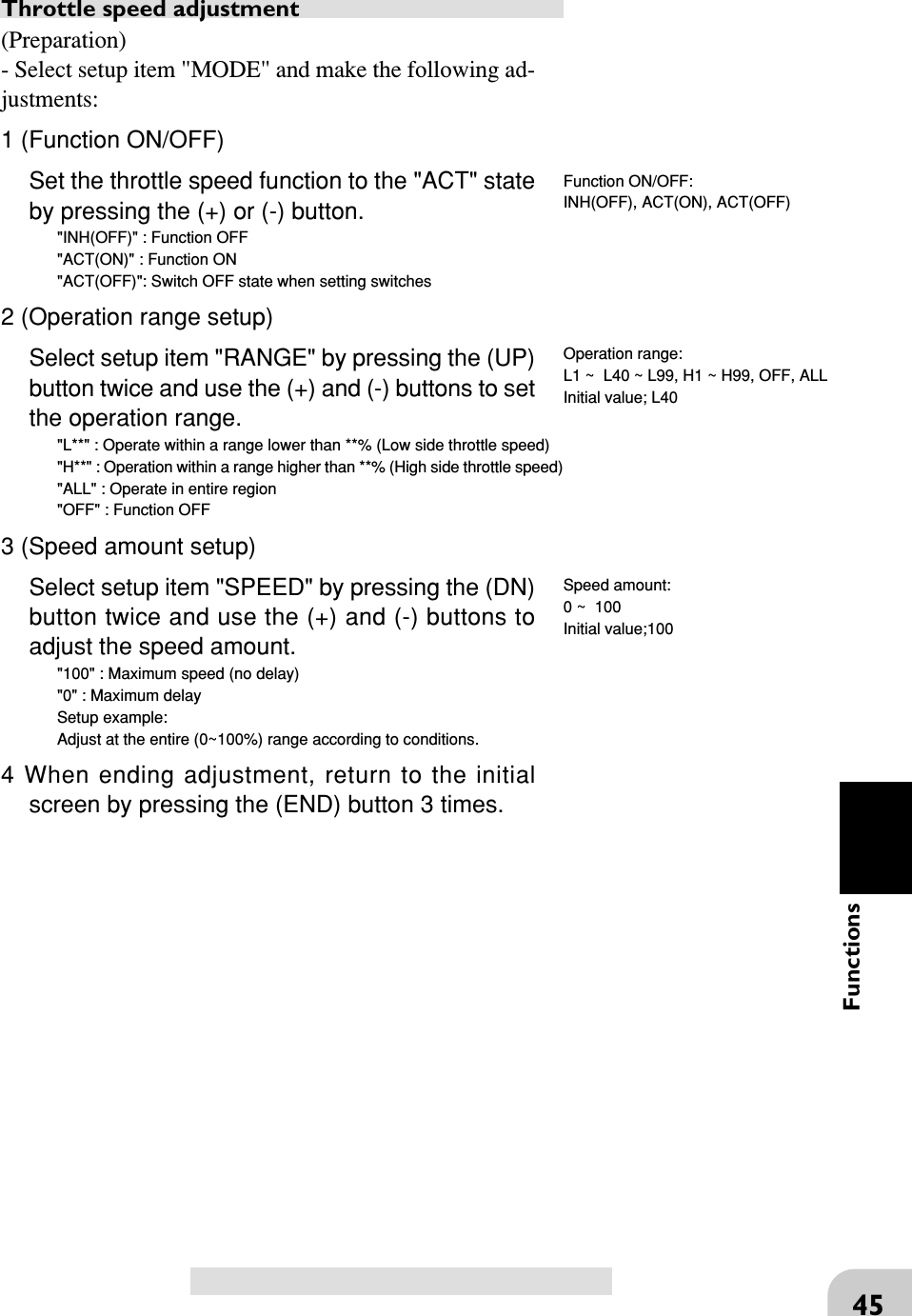
![44Functions(Initial screen) MENUUse the or button to select themenu screen.Press the button.Use the or button to select thefunction.Press the button. Calling the setup screen* When the direct call button is set,the setup screen is also called by thefollowing method: MENU SELECT DIRECT SELPress the button.Press the button setat this function.* Calling from menu screen Use the or button toselect the setup item.* blinks at the currentsetup item.(Initial screen)Throttle speed/TH-SPEED (Throttle system)Sudden trigger operation on a slippery road onlycauses the wheels to spin and the vehicle cannot ac-celerate smoothly. Setting the throttle speed func-tion reduces wasteful battery consumption while atthe same time permitting smooth, enjoyable opera-tion.OperationThrottle servo (amp) operation is delayed so that the drive wheels will not spin evenif the trigger is operated more than necessary. This delay function is not performedwhen the trigger is returned and at brake operation.- Low side throttle speed (See [Operation range setup].)Use when adjusting the speed from the neutral position to the set point.- High side throttle speed (See [Operation range setup].)Use when adjusting the high side speed from the set point.Remark: Regarding the throttle speed set value; the actual delay value variesdepending on the system (HRS, PCM, PPM). The delay when the HRS system is used is approximately 1/3 that of the PCM and PPM systems.Switch settingUse PS1, PS2, or PS3 to switch the throttle speed function ON/OFF.See the function select switch function (page ).Operation display* The LED blinks while the throttle speed function is on.No TH-SPEED/Tires slip and vehicle does not moveTH-SPEED/Smooth, quick starts possible* The LED blinks while the throttlespeed function is on.* The black part of the bar graph is theoperation range.* Throttle trigger position* "L40" indicates operation below40%.Adjustment buttons- Use the (+) and (-) buttons to makeadjustments.- Return to the initial value by pressingthe (+) and (-) buttons simultaneously(approx. 1 sec).Setup itemsRA NGE : Operation rangeSPEED : Speed amountMODE : Function ON/OFF](https://usermanual.wiki/Futaba/FP-PK-FM-75B.User-Manual-I/User-Guide-856693-Page-44.png)