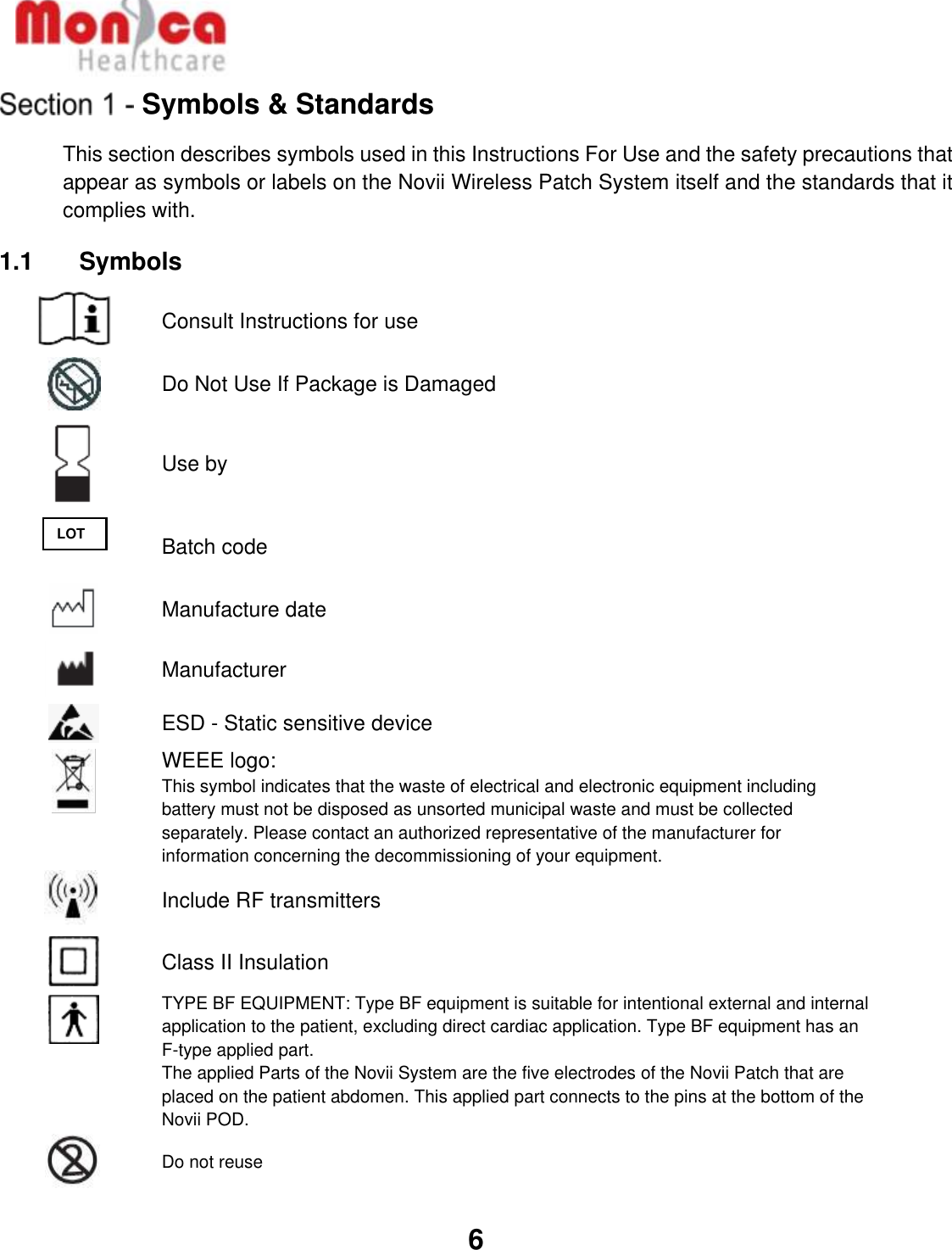
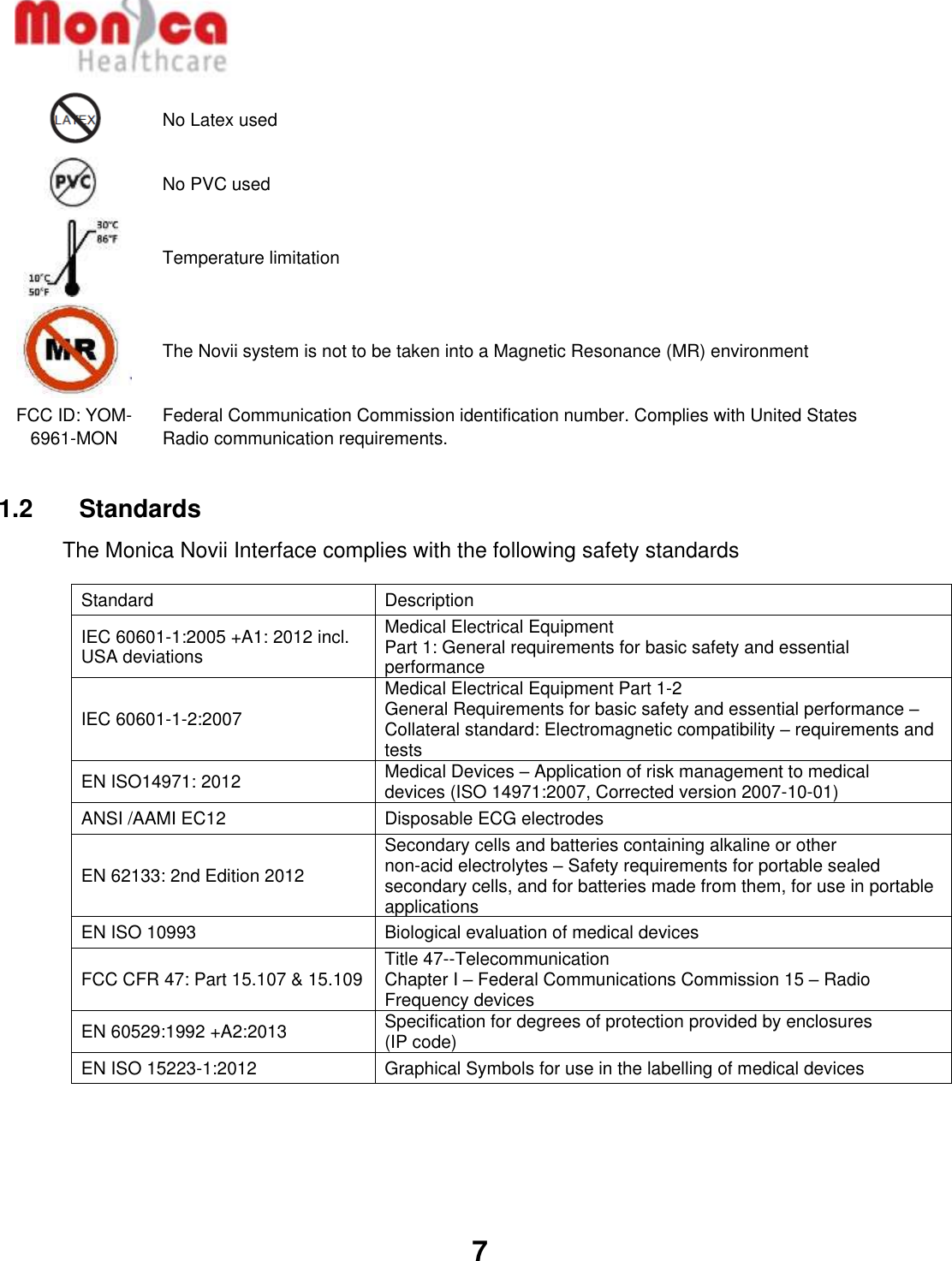
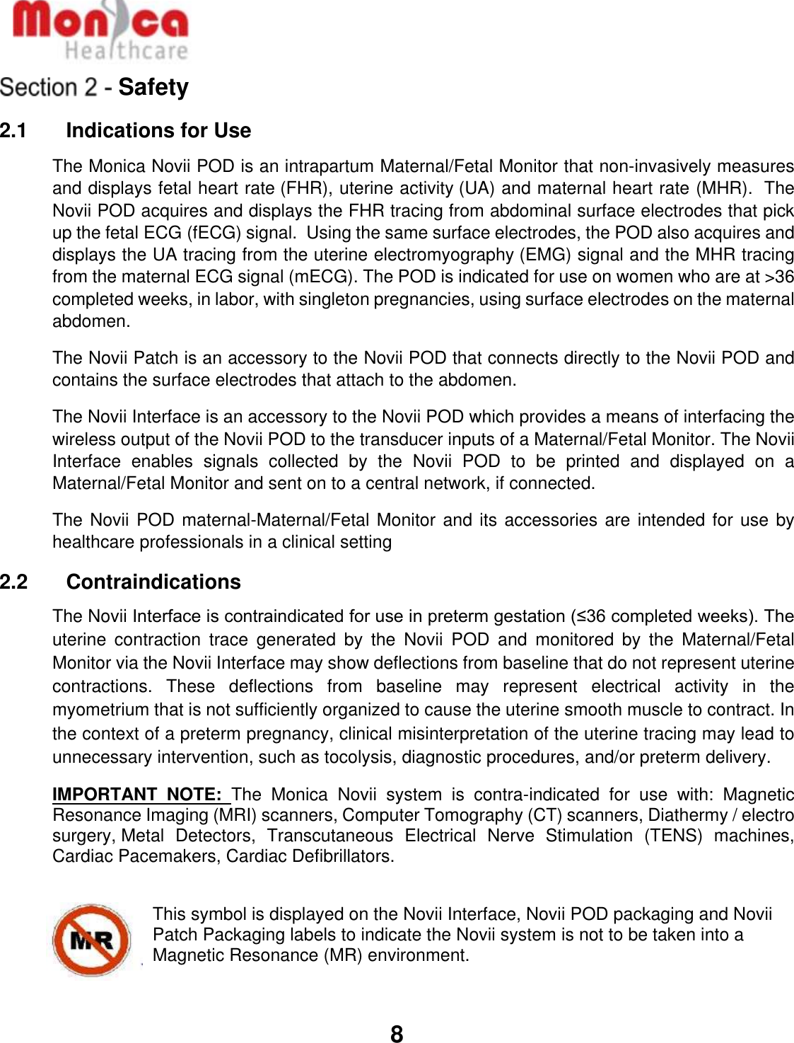
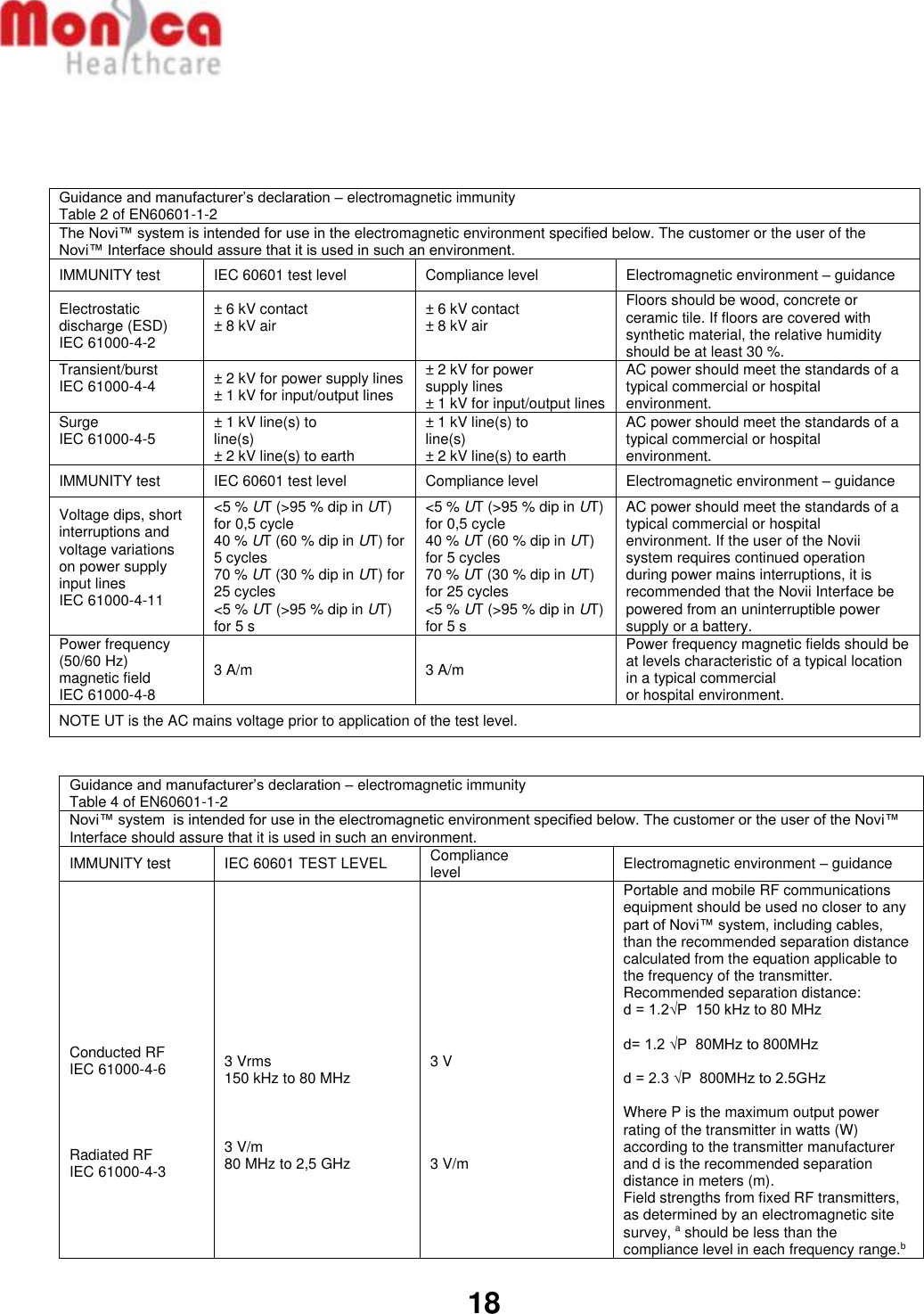
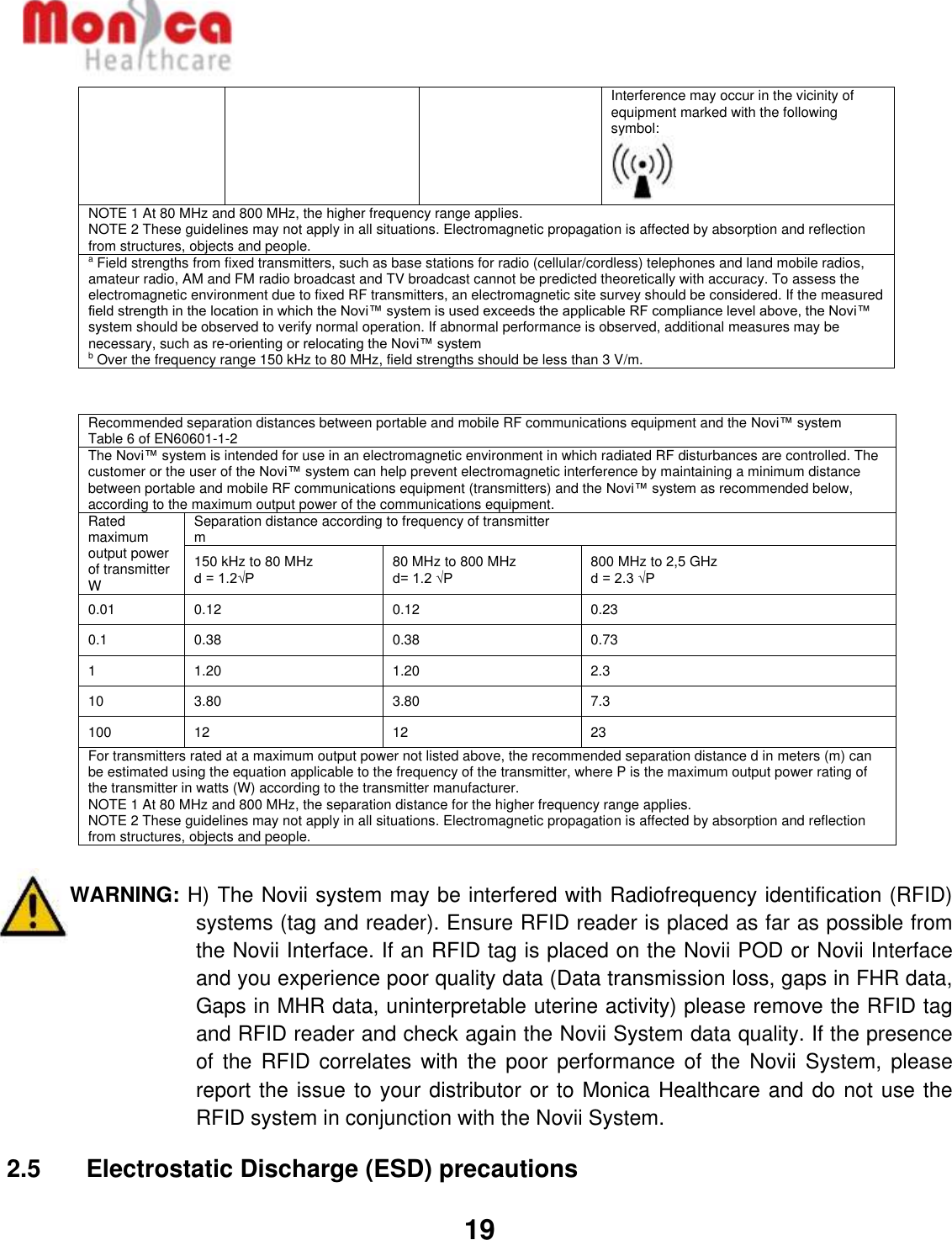
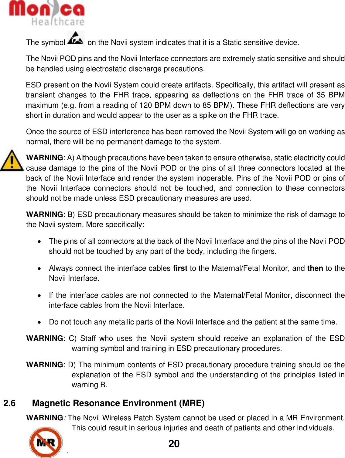
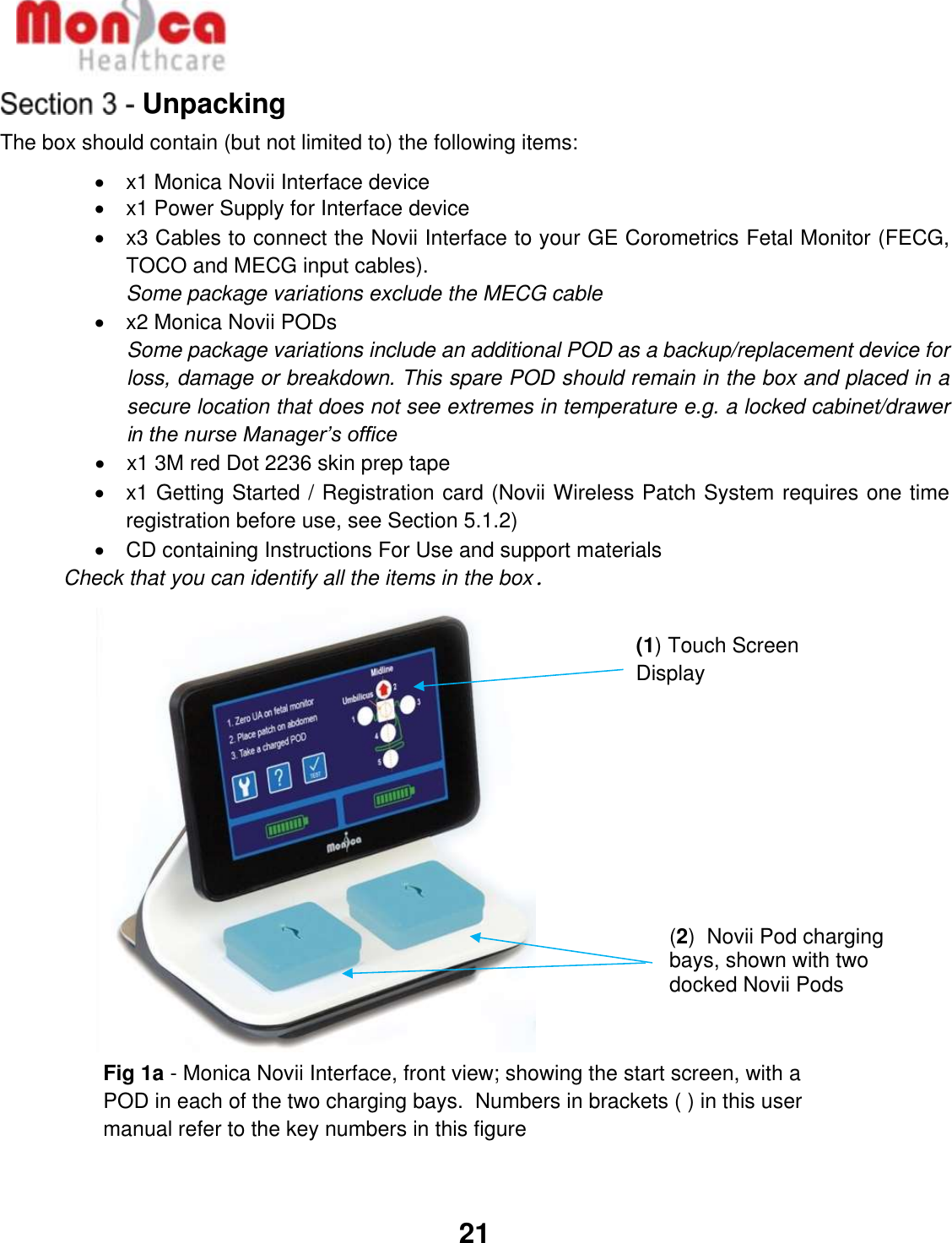
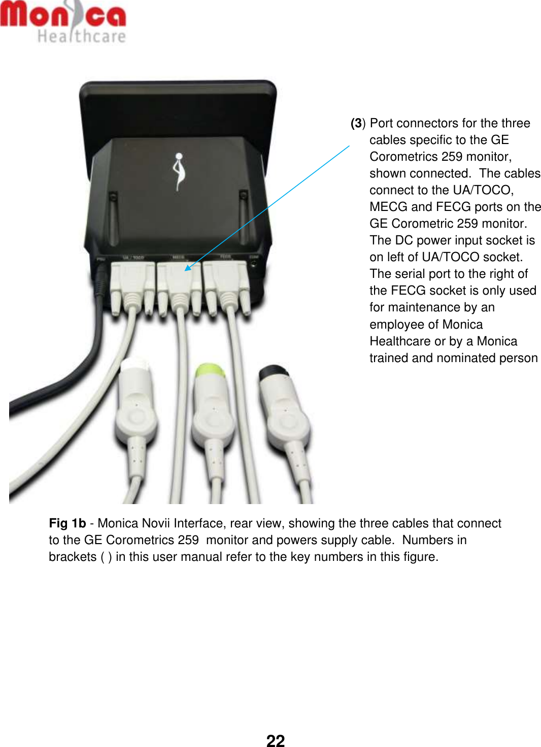
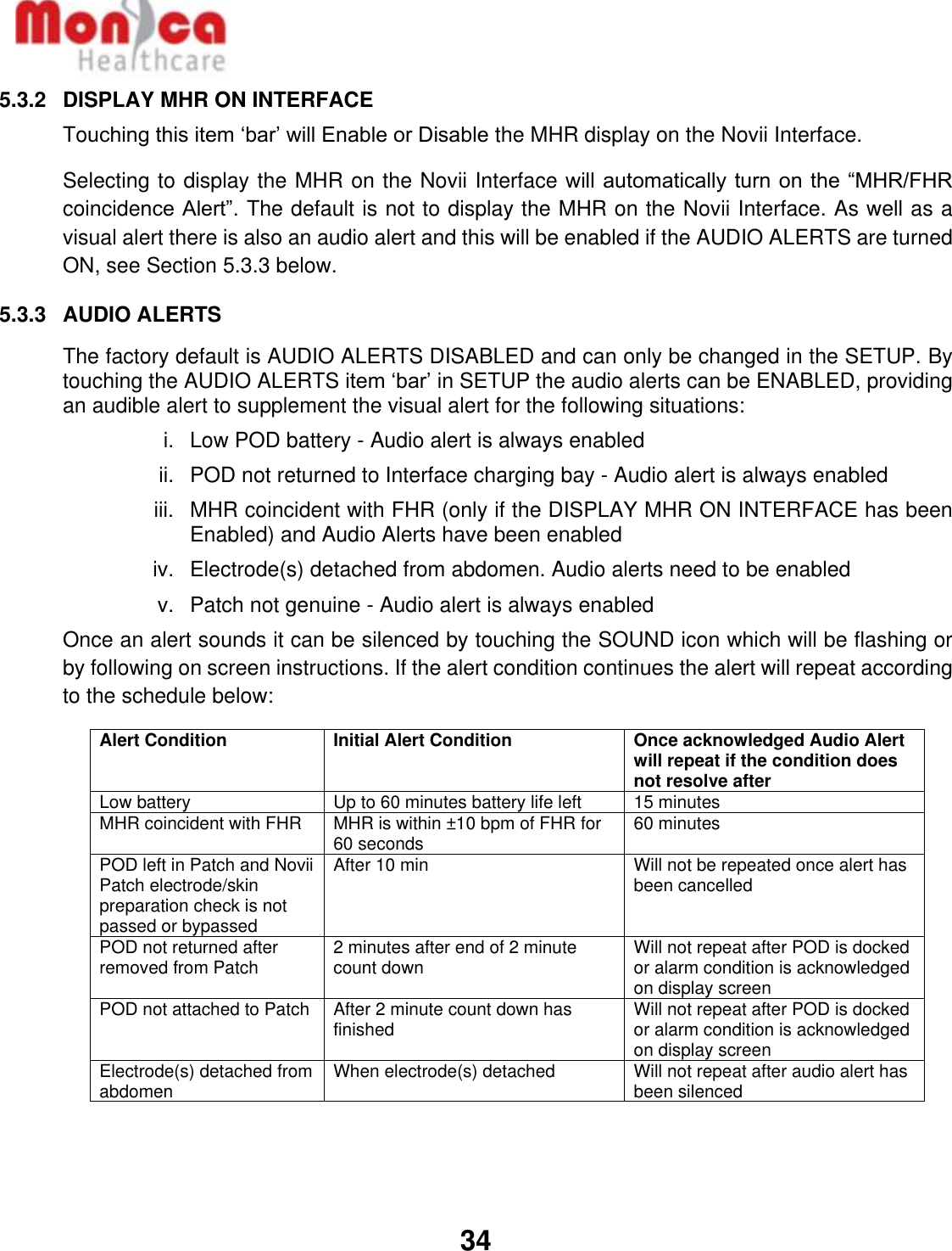
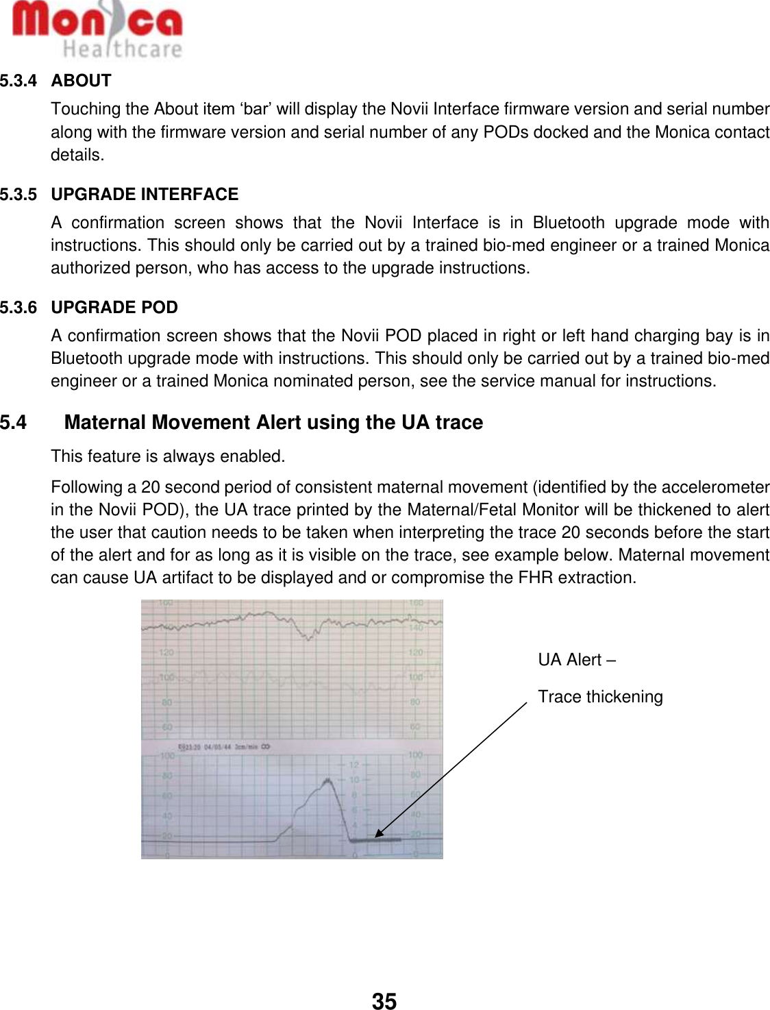
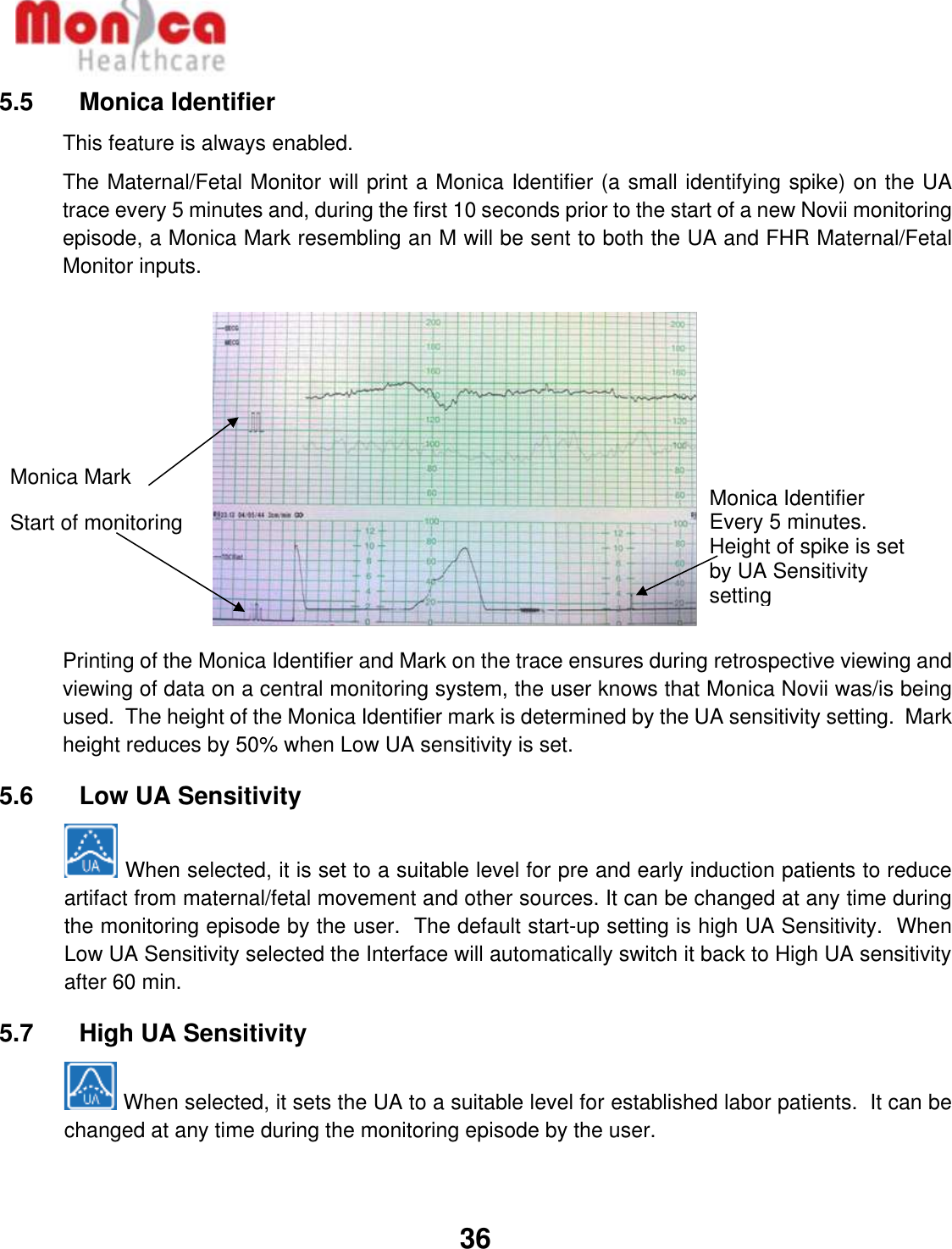
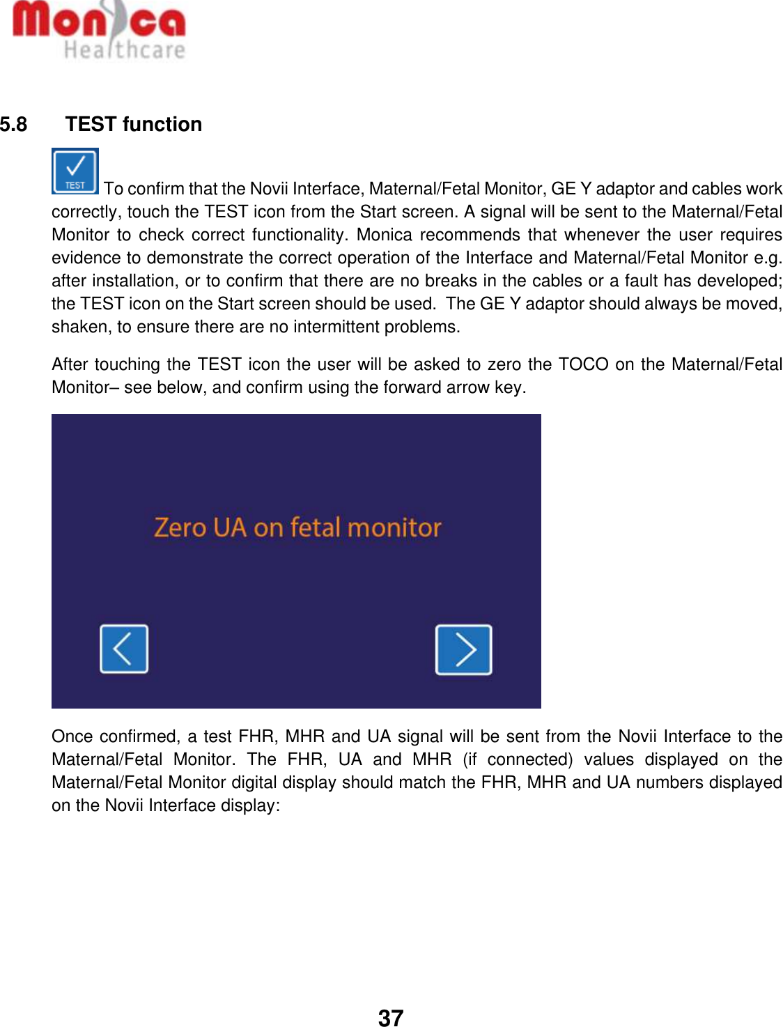
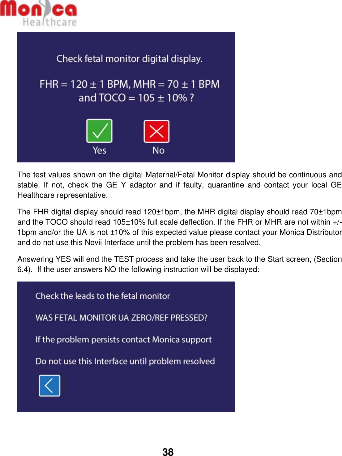
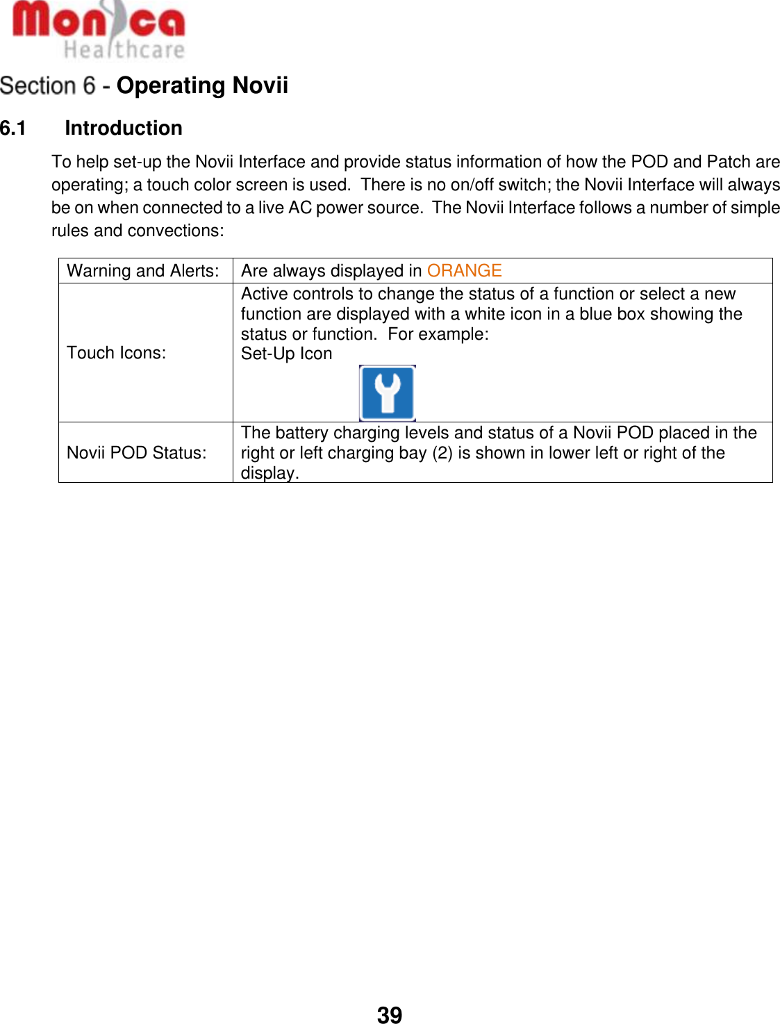
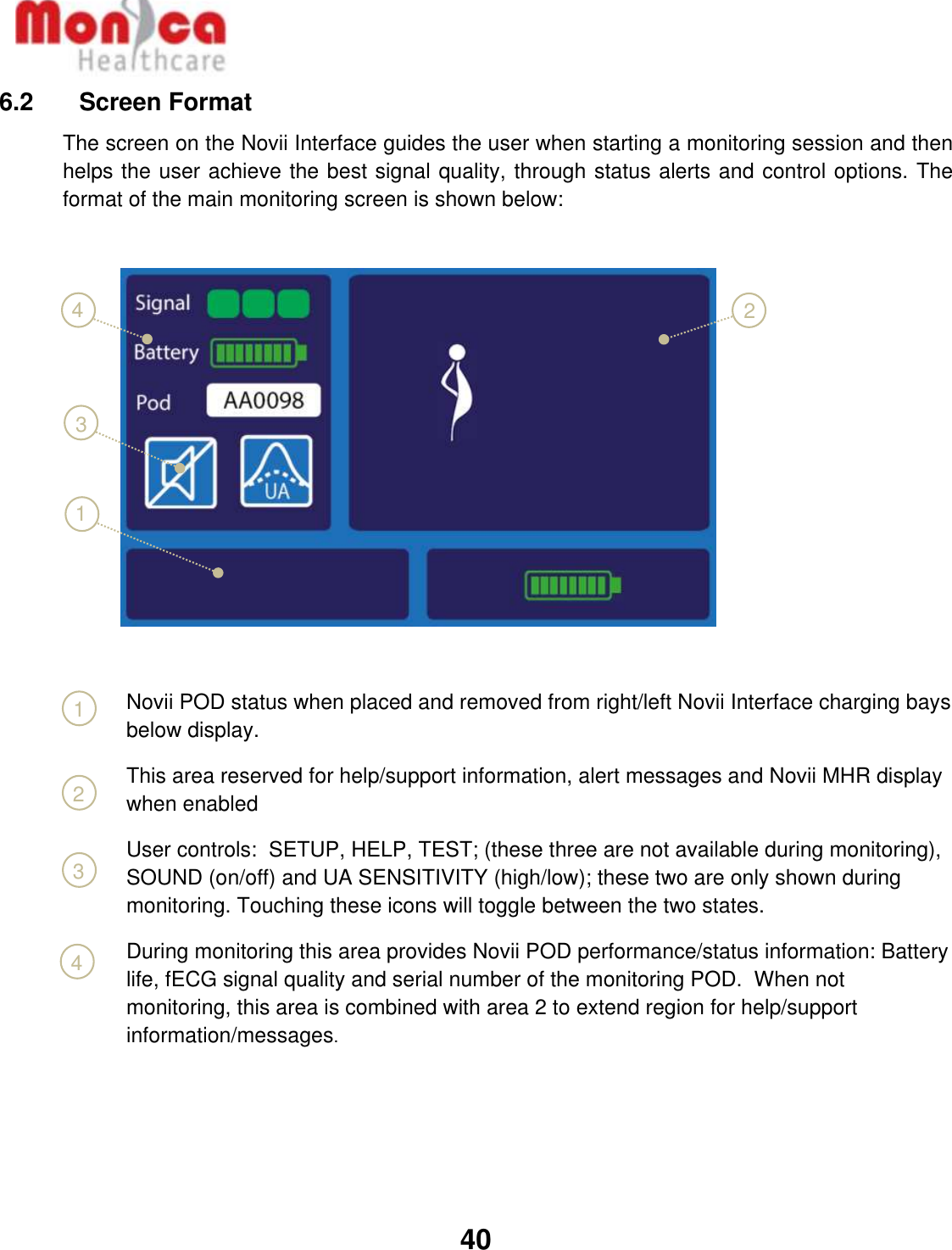
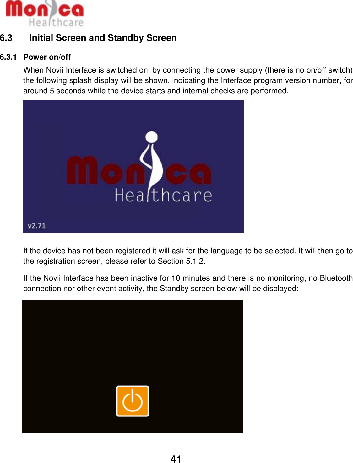
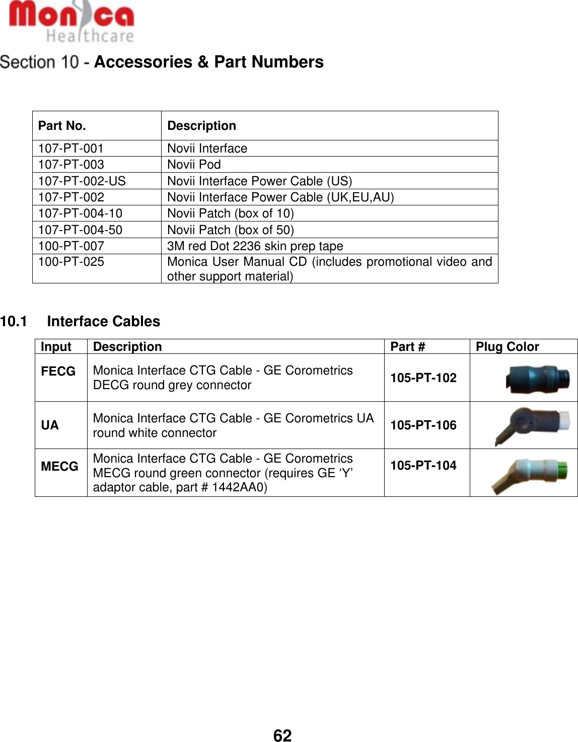
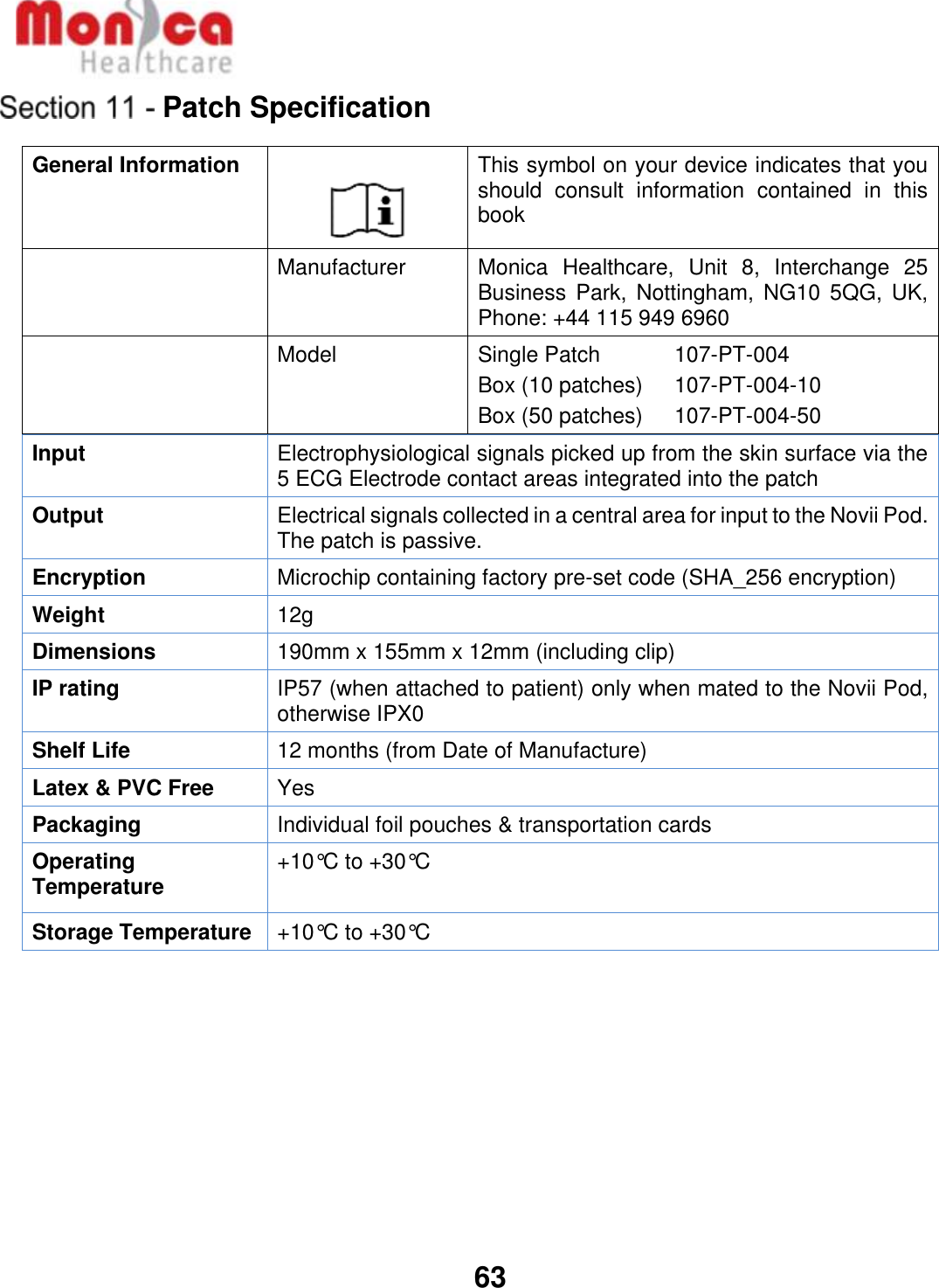
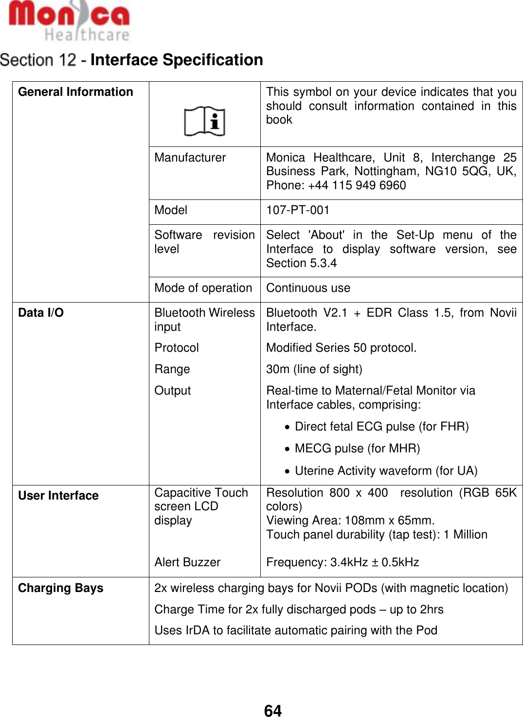
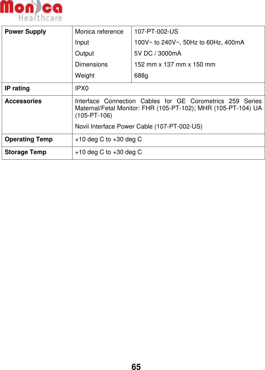
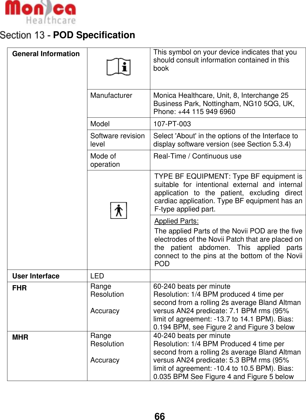
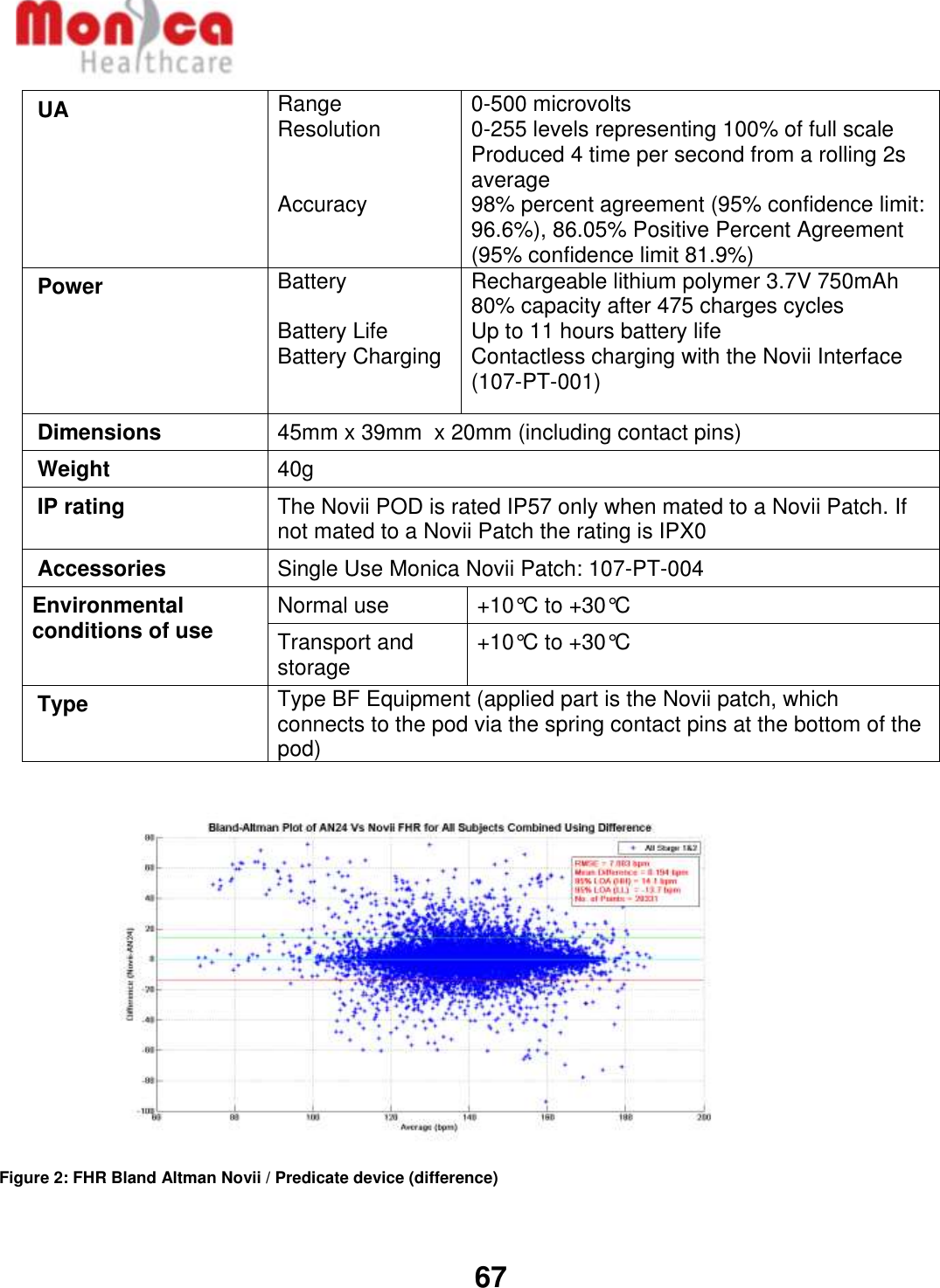
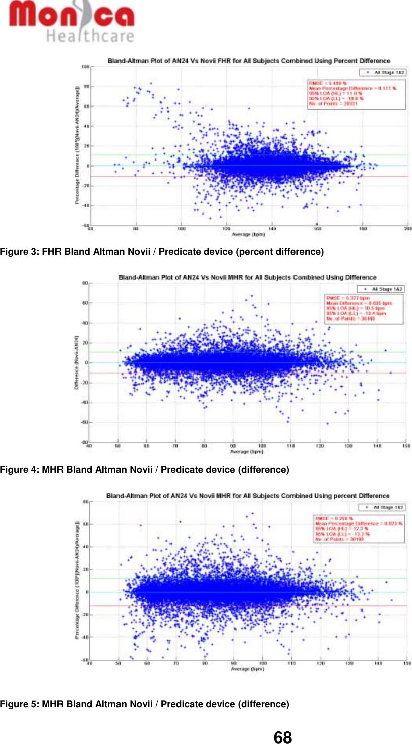
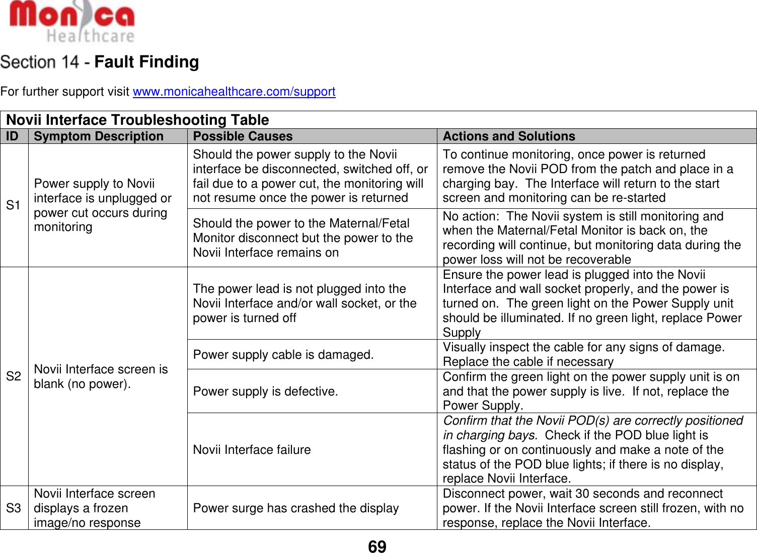
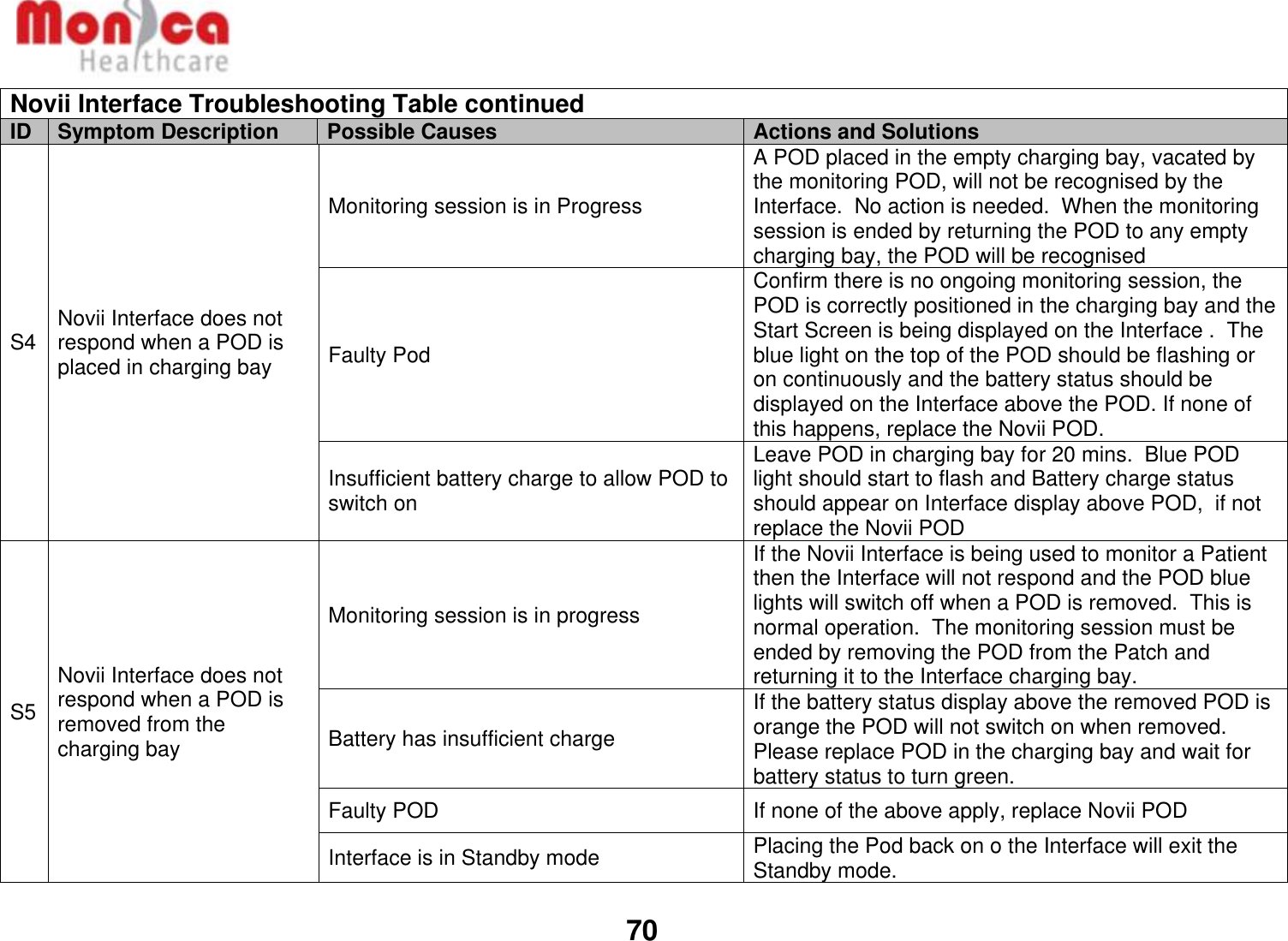
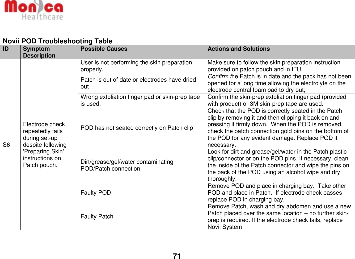
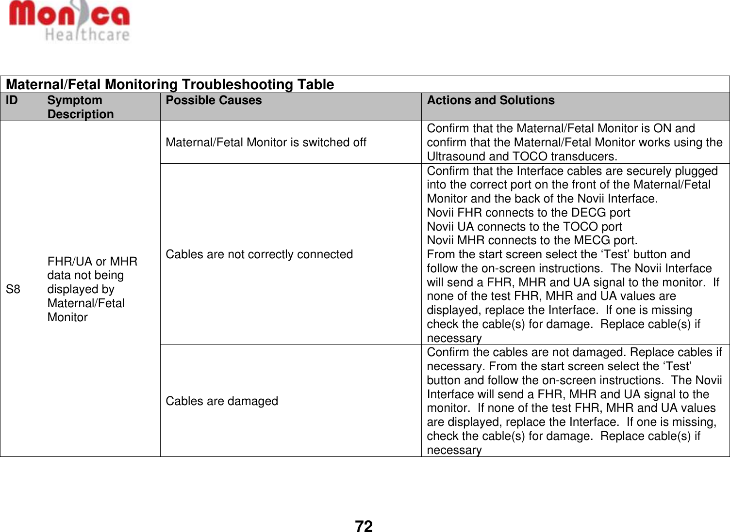
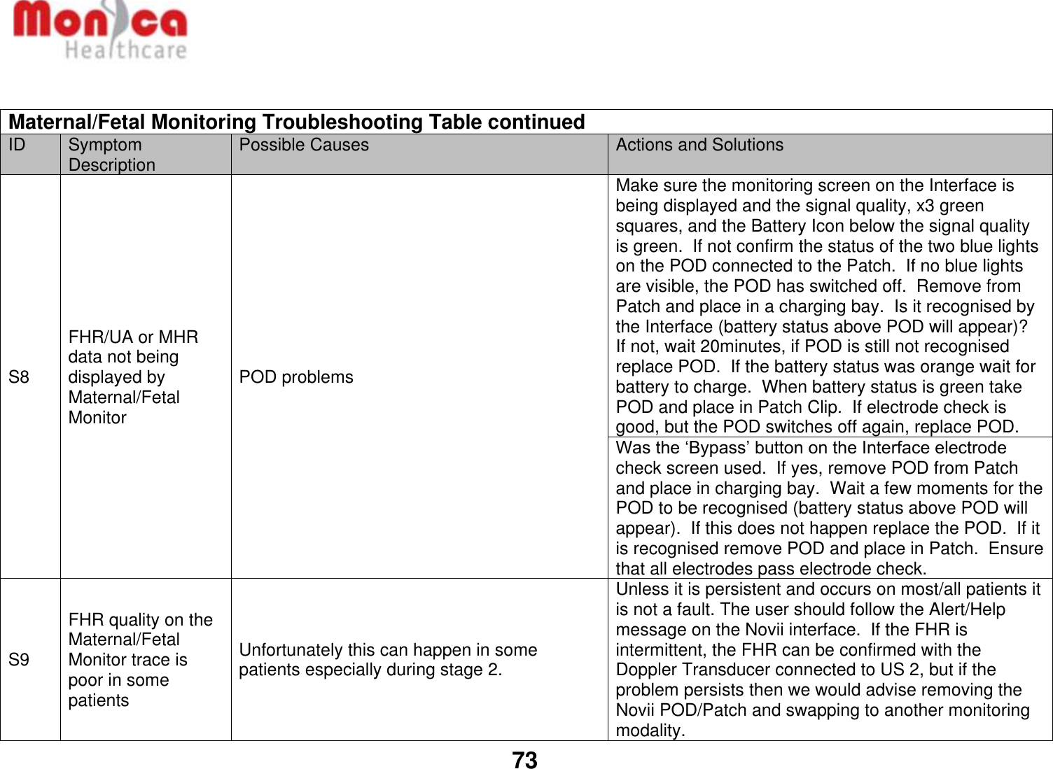
GE Healthcare 6961-MON Novii Intrapartum Maternal/Fetal monitor User Manual 107 PT 005 ENrevP Novii IFU
GE Healthcare Novii Intrapartum Maternal/Fetal monitor 107 PT 005 ENrevP Novii IFU
UserManual.wiki
>
GE Healthcare
>
6961-MON User Manual
>
107-PT-005-ENrevP-Novii IFU
Contents
1.
107-PT-005-ENrevP-Novii IFU
2.
100-TF-056 rev1 UC Guide
3.
107-PT-006 USrev2_Novii - Getting Started Guide
4.
107-TF-100-USrev7_Novii Technical Datasheet
5.
MH Novii 6pp Brochure -107-TF-102-ENrevA
6.
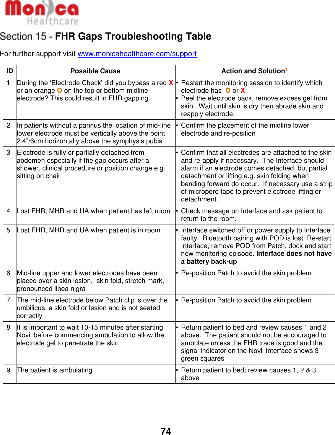
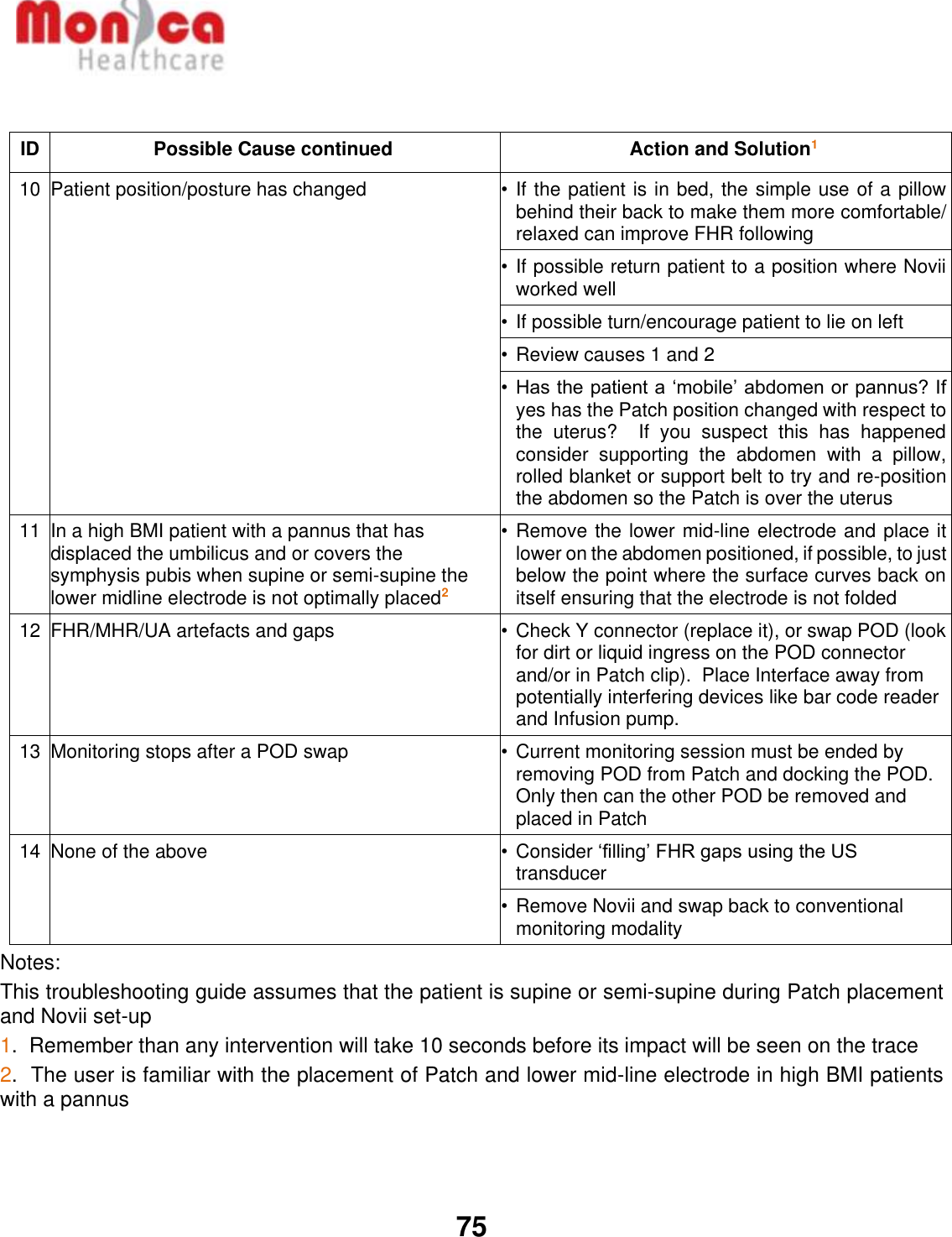
Novii - FHR Gaps Troubleshooting Guide 107-PT-008-USRev1
107-PT-005-ENrevP-Novii IFU
Navigation menu
Upload a User Manual
Namespaces
Wiki Guide
HTML
PDF
Info
Views
User Manual
Discussion / Help
Navigation