GE MDS DS-SD4-1 Data Transceiver User Manual 4670D SD x710 Reference
GE MDS LLC Data Transceiver 4670D SD x710 Reference
UserManual.wiki
>
GE MDS
>
DS SD4 1 User Manual
Manual
Navigation menu
Upload a User Manual
Namespaces
Wiki Guide
HTML
PDF
Info
Views
User Manual
Discussion / Help
Navigation


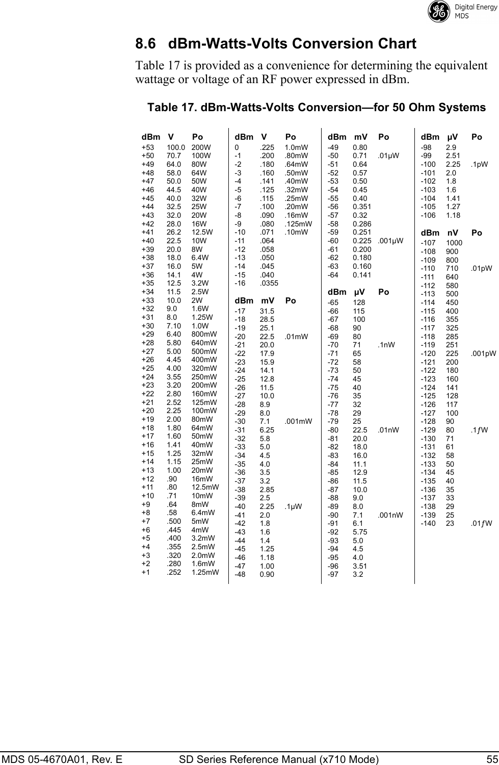
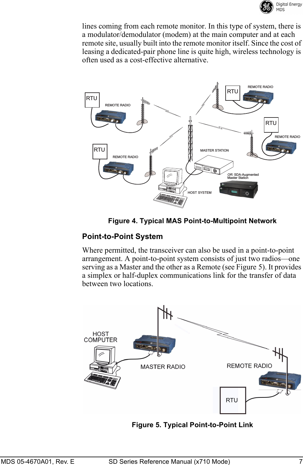
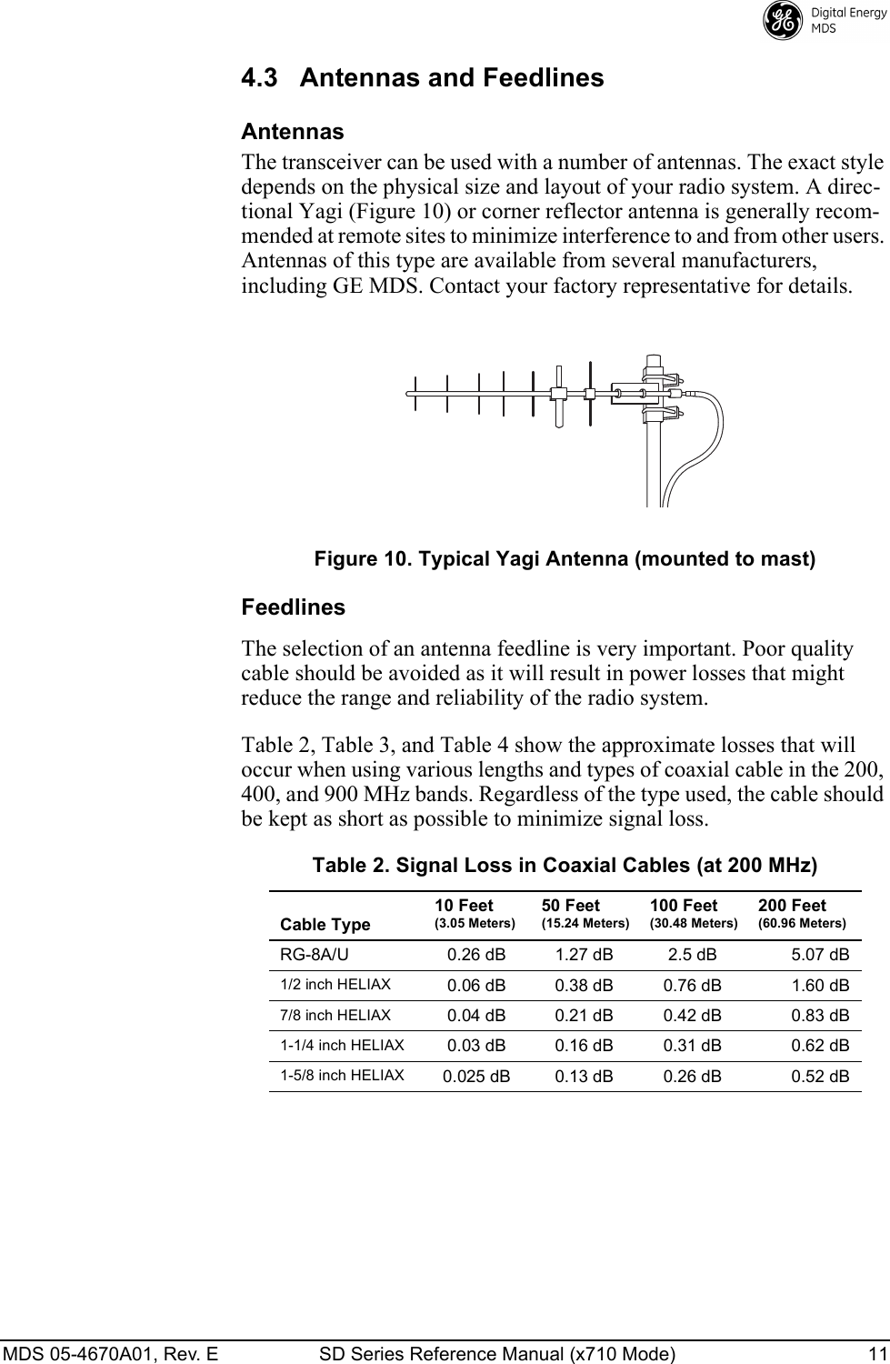
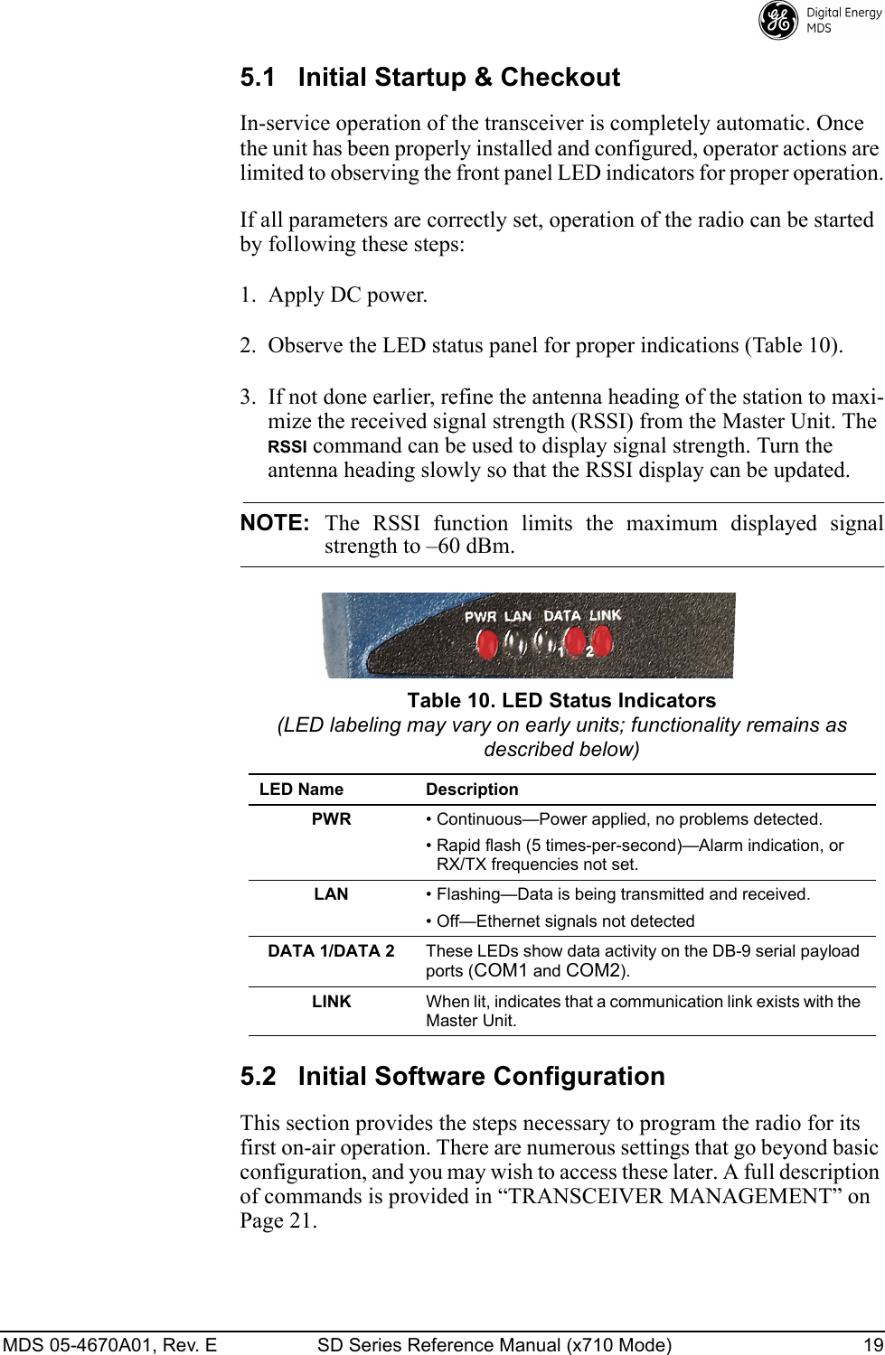
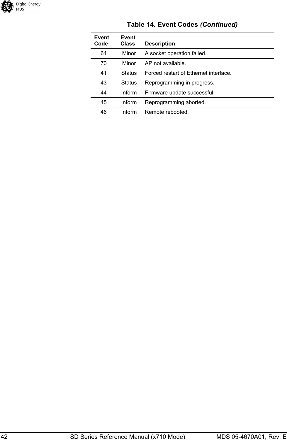
![MDS 05-4670A01, Rev. E SD Series Reference Manual (x710 Mode) ii Entering Commands ......................................................................................................................216.2 Detailed Command Descriptions .................................................................................................24AK ..................................................................................................................................................25ALARM...........................................................................................................................................25AMASK [0000 0000–FFFF FFFF]..................................................................................................25ASENSE [HI, LO] ...........................................................................................................................25AUDIO [ON, OFF] ..........................................................................................................................26BAUD [xxxxx abc] ..........................................................................................................................26BIN [DATA, CLEAR] .......................................................................................................................26BOOT.............................................................................................................................................26BUFF [ON, OFF] ............................................................................................................................26CKEY [ON–OFF]............................................................................................................................27CTS [0–255]...................................................................................................................................27CTSHOLD [0–60000].....................................................................................................................27DATAKEY [ON, OFF] .....................................................................................................................28DEV................................................................................................................................................28DEVICE [DCE, CTS KEY]..............................................................................................................28DKEY .............................................................................................................................................28DLINK [ON/OFF/xxxx]....................................................................................................................28DTYPE [NODE/ROOT] ..................................................................................................................29DUMP ............................................................................................................................................29EMP [ON/OFF]...............................................................................................................................29ETHADDR......................................................................................................................................29FORCEALARM [ON or OFF] .........................................................................................................29FORCEDCD [ON or OFF]..............................................................................................................29HELP..............................................................................................................................................29INIT ................................................................................................................................................ 30INIT [SDx] ......................................................................................................................................30INIT [P-20]...................................................................................................................................... 30IPCONFIG...................................................................................................................................... 31KEY................................................................................................................................................31MENU ............................................................................................................................................ 31MODEL1 ........................................................................................................................................31MODEL2 ........................................................................................................................................31MODEM [xxxx] ...............................................................................................................................31OWM [XXX...].................................................................................................................................33OWN [XXX...] .................................................................................................................................33PORT [RS232, RS485] ..................................................................................................................34PTT [0–255] ...................................................................................................................................34PTTSIG [OFF, LOW, HI].................................................................................................................34PWR [20–37]..................................................................................................................................34RESTORECONFIG........................................................................................................................34RESTOREDEFAULTS ...................................................................................................................34RMODE [X710, TRANSPARENT, PACKET, CMAC, HELP] ..........................................................34RSSI...............................................................................................................................................34RTSKEY [ON, OFF] .......................................................................................................................35RTU [ON/OFF/0-80] .......................................................................................................................35RX [xxx.xxxx] .................................................................................................................................35RXATTN [ON or OFF] .................................................................................................................... 35RXLEVEL [–20 to 0].......................................................................................................................35RXTOL [NORMAL or CUSTOM] ....................................................................................................36](https://usermanual.wiki/GE-MDS/DS-SD4-1/User-Guide-2653332-Page-4.png)
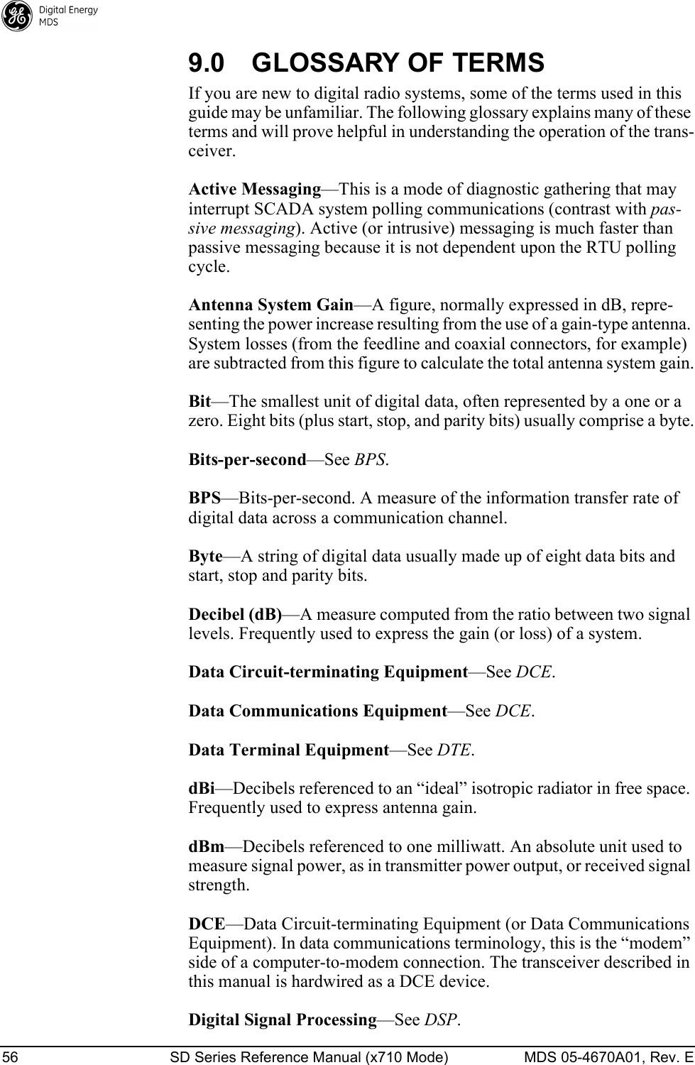
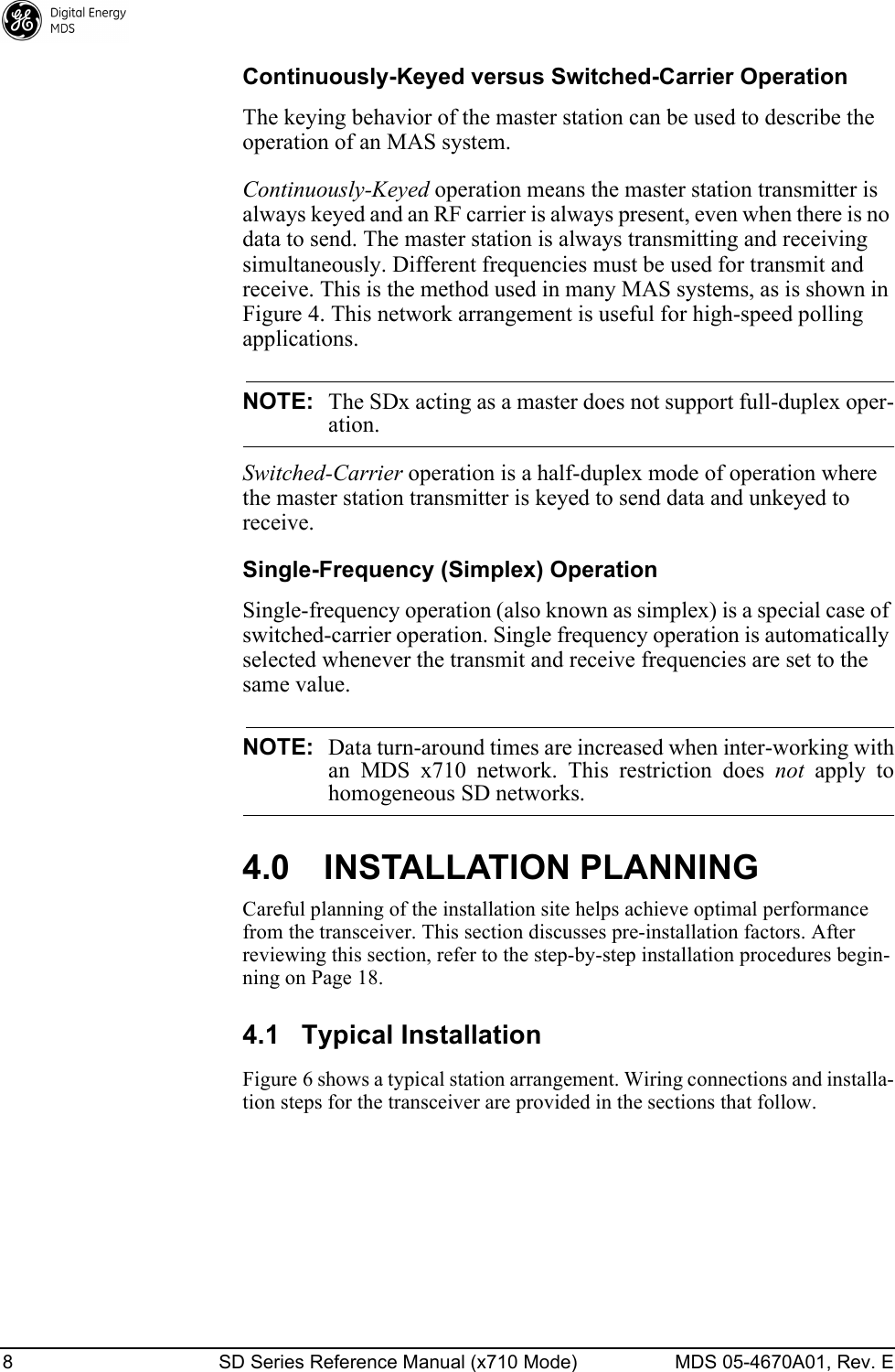
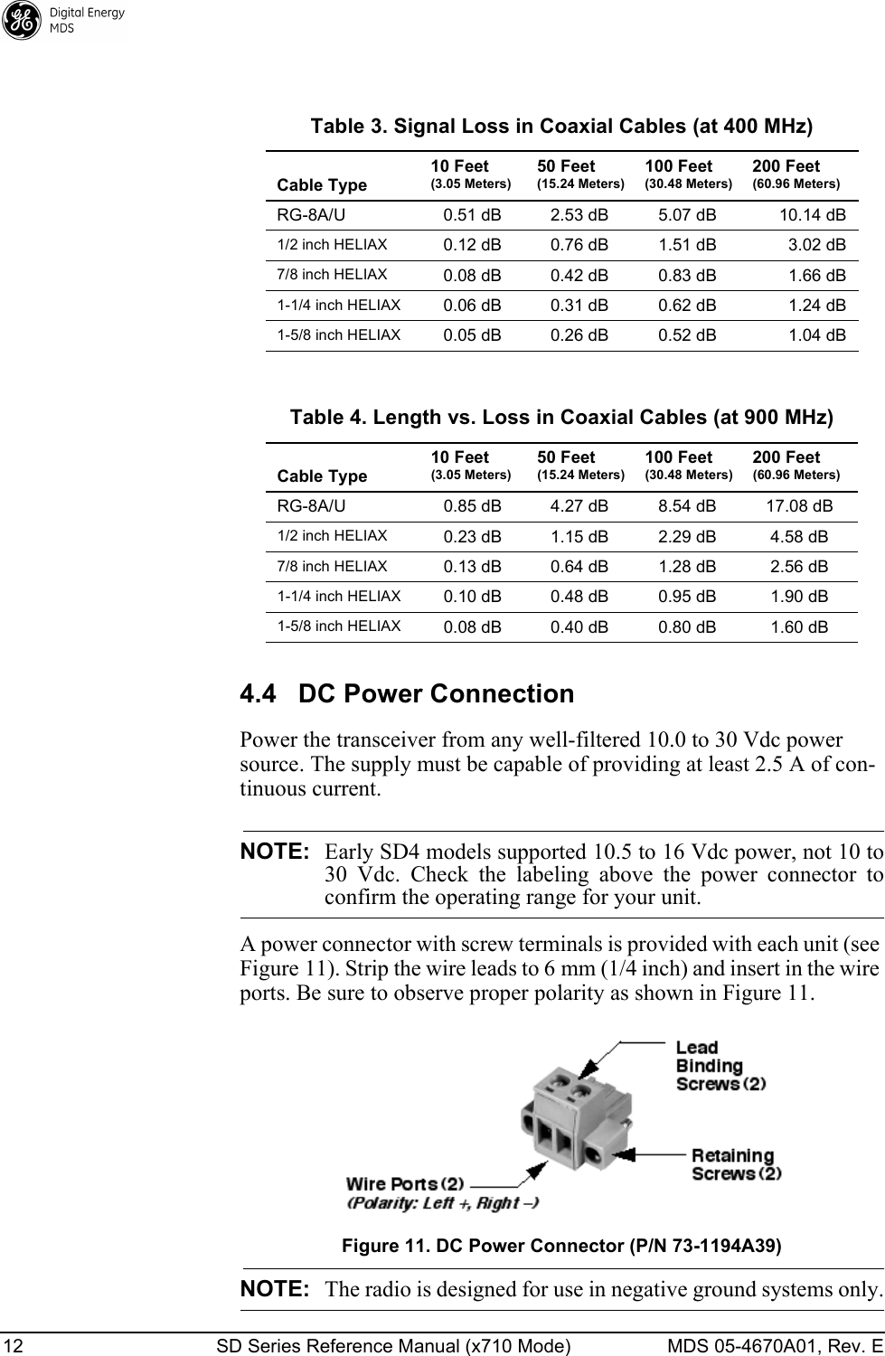
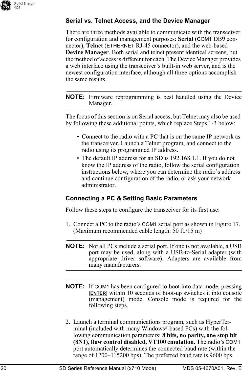
![MDS 05-4670A01, Rev. E SD Series Reference Manual (x710 Mode) iii RXTOT [NONE, 1-1440] ................................................................................................................36SAVECONFIG................................................................................................................................36SCD [0-255] ...................................................................................................................................36SER................................................................................................................................................36SHOW [DC, PWR] .........................................................................................................................36SNR ............................................................................................................................................... 36SPECTRUM [xxx.xx]......................................................................................................................37SQUELCH [AUTO, BYPASSED]....................................................................................................37SREV .............................................................................................................................................37STAT ..............................................................................................................................................38SWC [ON, OFF] .............................................................................................................................38TFTP .............................................................................................................................................. 38TEMP ............................................................................................................................................. 38TOT [1-255, ON, OFF] ...................................................................................................................39TX [xxx.xxxx].................................................................................................................................. 39TXLEVEL [–20 to 0, AUTO] ...........................................................................................................39UNIT [10000...65000].....................................................................................................................39UPTIME .........................................................................................................................................39VERSION.......................................................................................................................................397.0 TROUBLESHOOTING........................................................................................................ 407.1 LED Indicators .............................................................................................................................407.2 Event Codes ................................................................................................................................40Checking for Alarms—STAT command..........................................................................................40Major Alarms vs. Minor Alarms ......................................................................................................41Event Code Definitions ..................................................................................................................418.0 TECHNICAL REFERENCE ................................................................................................ 438.1 Technical Specifications .............................................................................................................438.2 Performing Network-Wide Remote Diagnostics ..........................................................................458.3 User-Programmable I/O Functions - Pending .............................................................................468.4 Analog Operation of the Transceiver ........................................................................................... 46Physical Interface...........................................................................................................................47Operational Characteristics............................................................................................................478.5 Upgrading the Radio’s Firmware .................................................................................................48Web Method...................................................................................................................................49TFTP Method .................................................................................................................................50Serial Transfer Method...................................................................................................................52Error Messages During File Transfers ...........................................................................................548.6 dBm-Watts-Volts Conversion Chart .............................................................................................559.0 GLOSSARY OF TERMS..................................................................................................... 56Copyright and TrademarkThis manual and all software described herein is protected by Copyright: 2012 GE MDS, LLC. All rights reserved. GE MDS, LLC reserves its right to correct any errors and omissions in this publi-cation. Modbus® is a registered trademark of Schneider Electric Corporation. All other trademarks and product names are the property of their respective owners.](https://usermanual.wiki/GE-MDS/DS-SD4-1/User-Guide-2653332-Page-5.png)
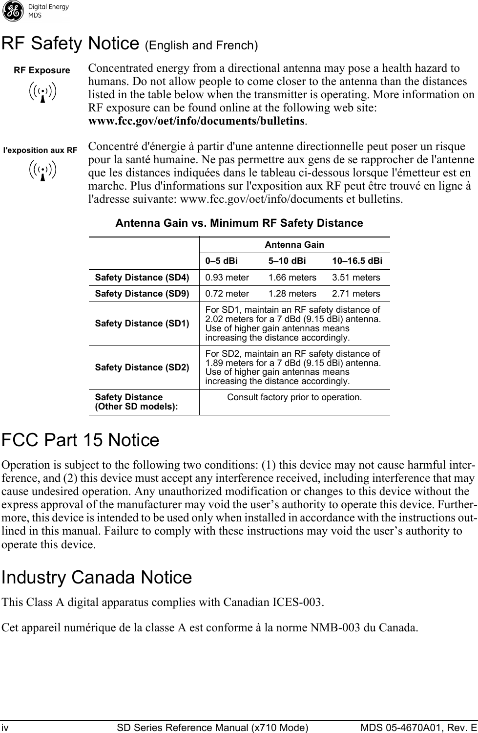

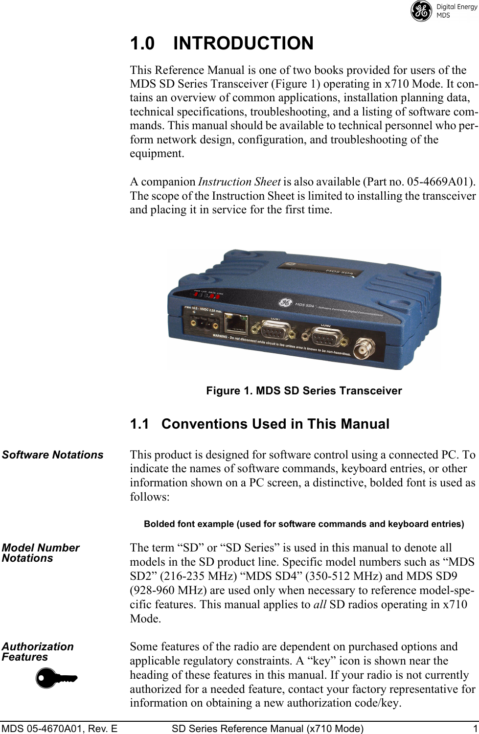
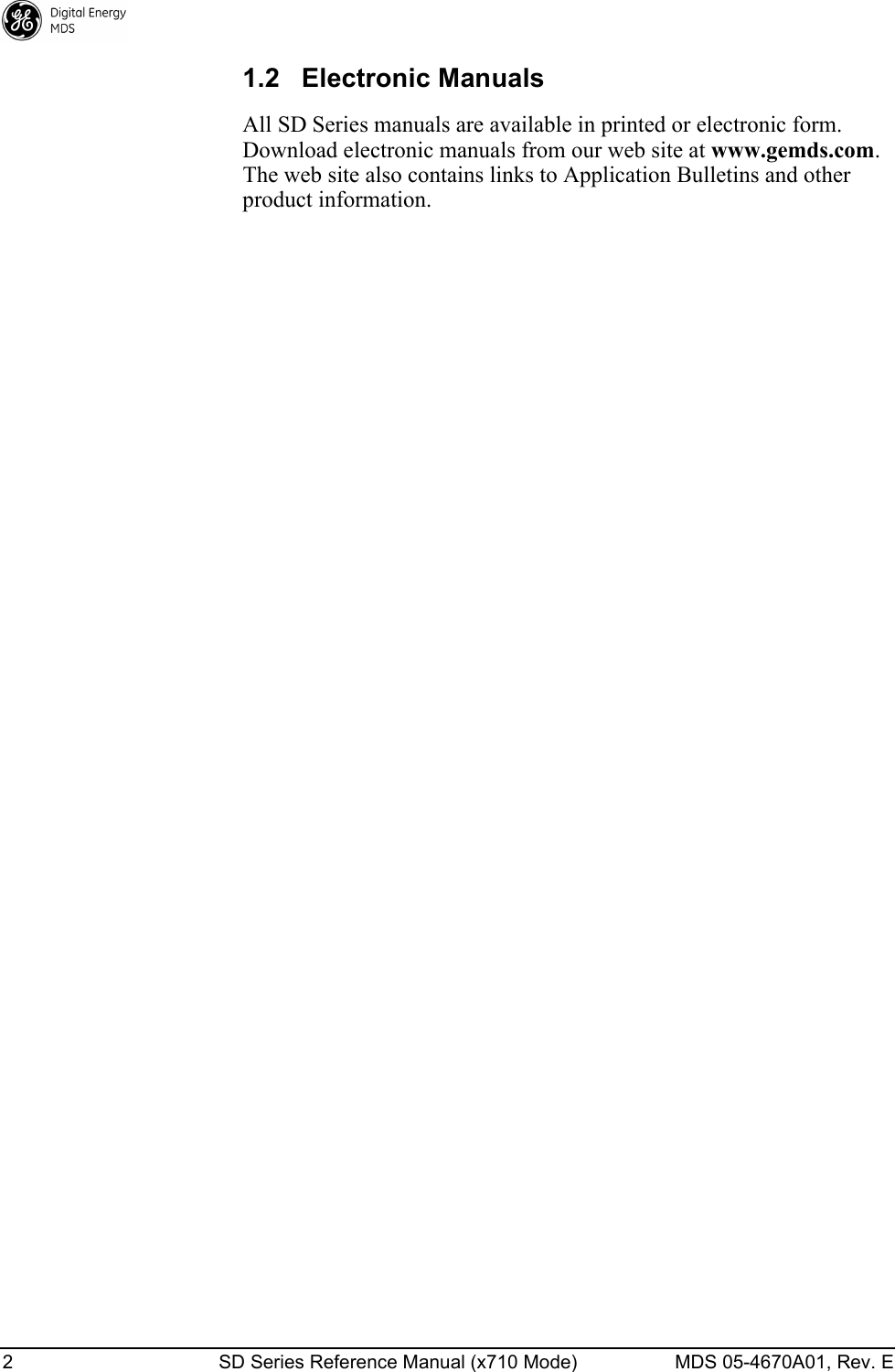
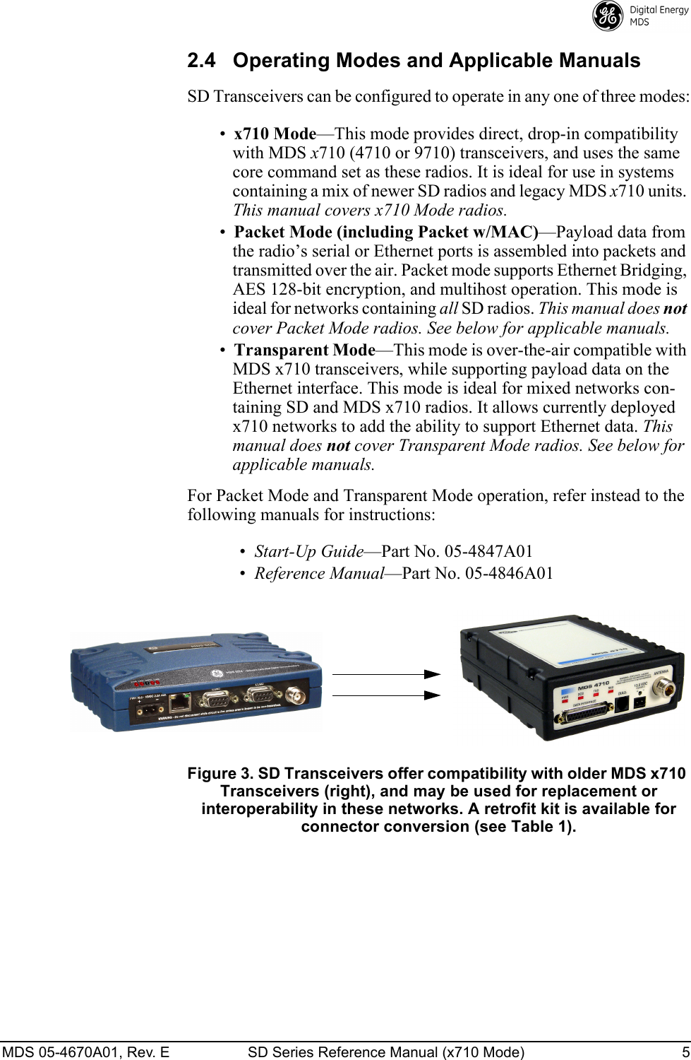
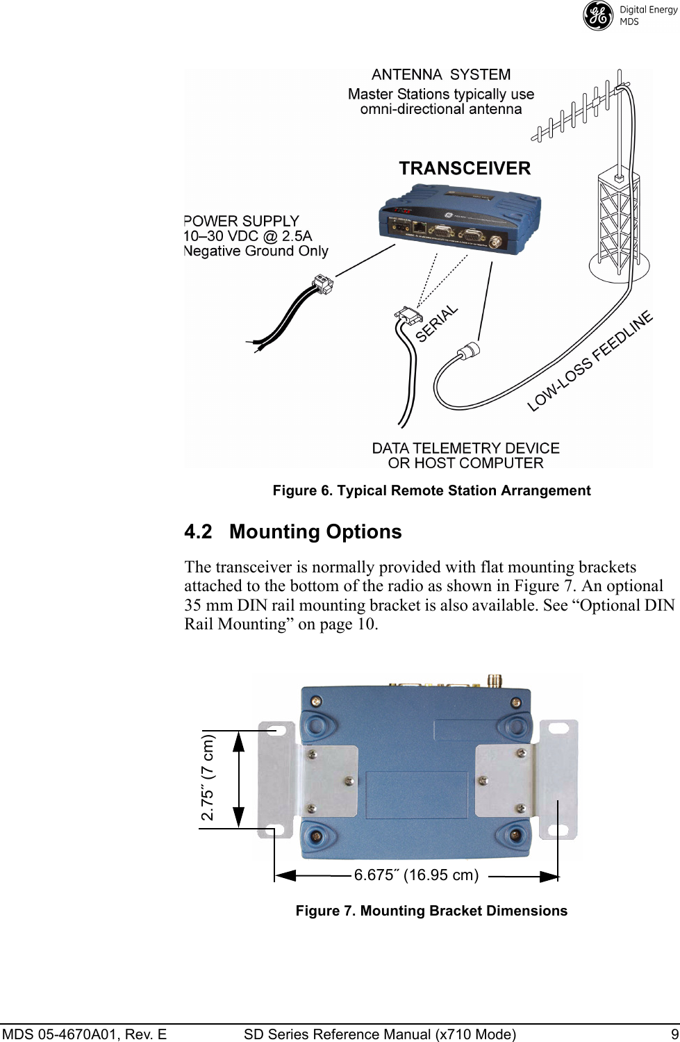
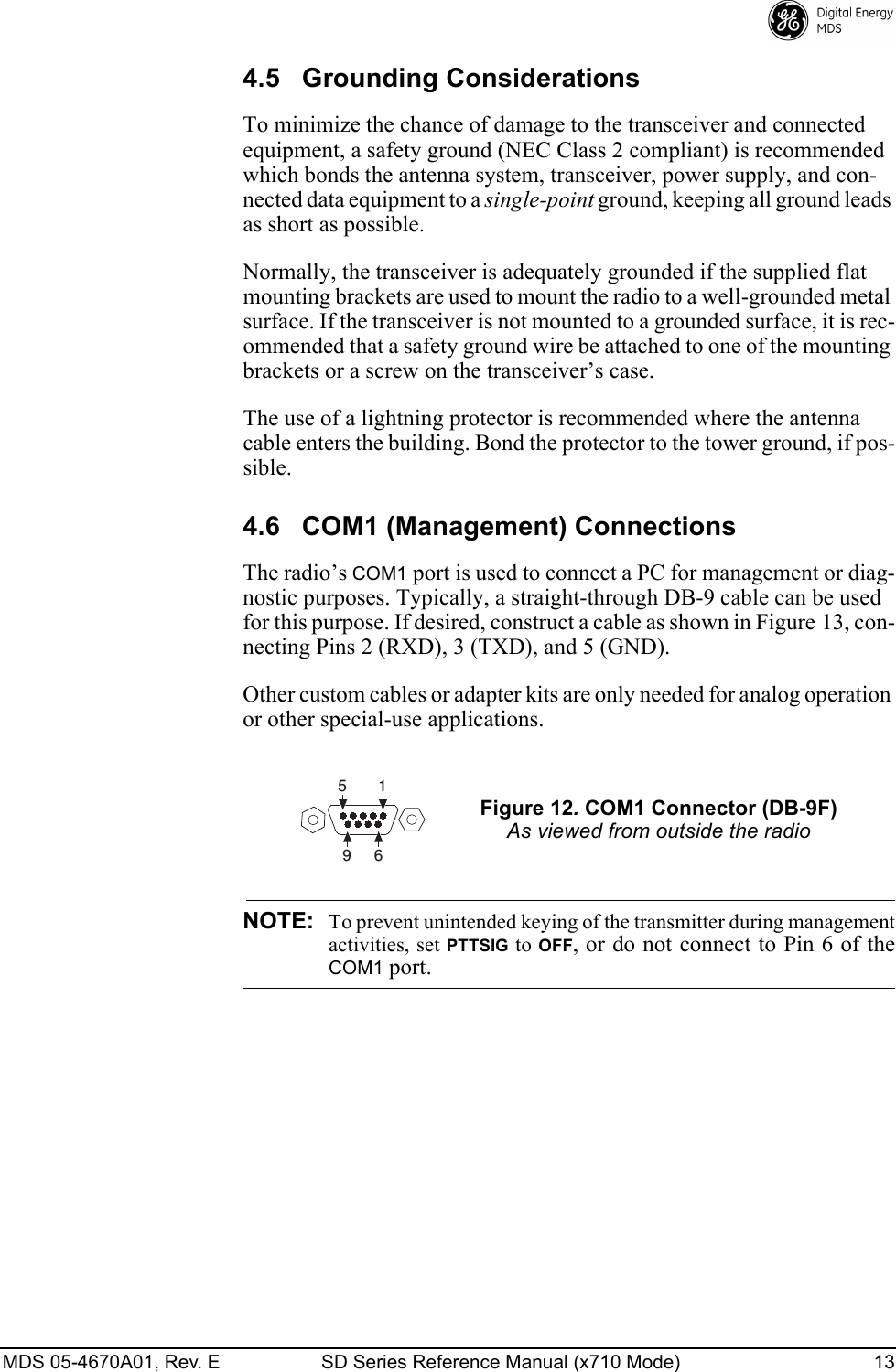
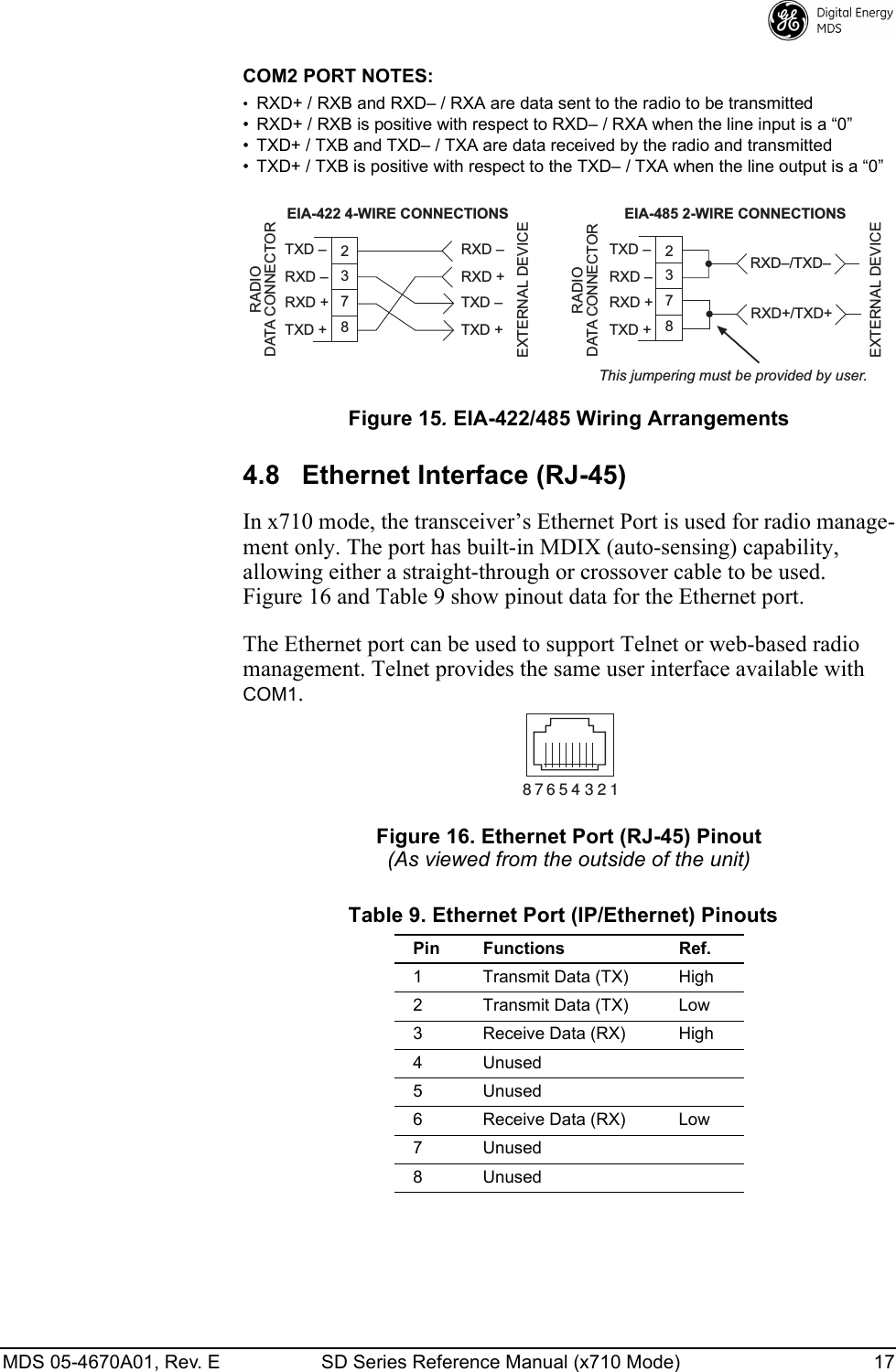
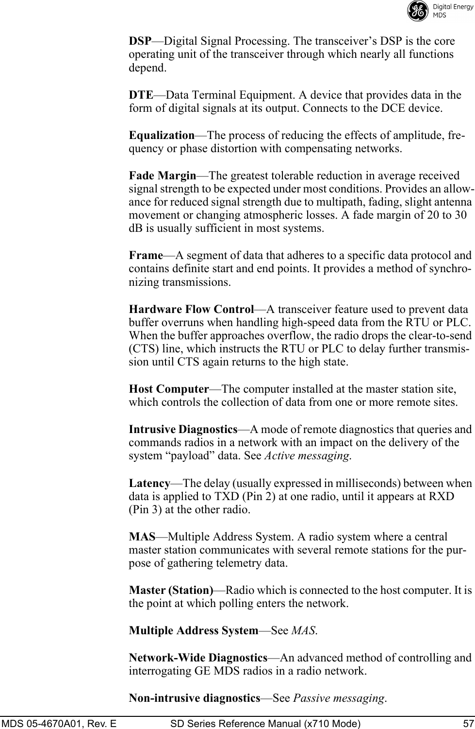
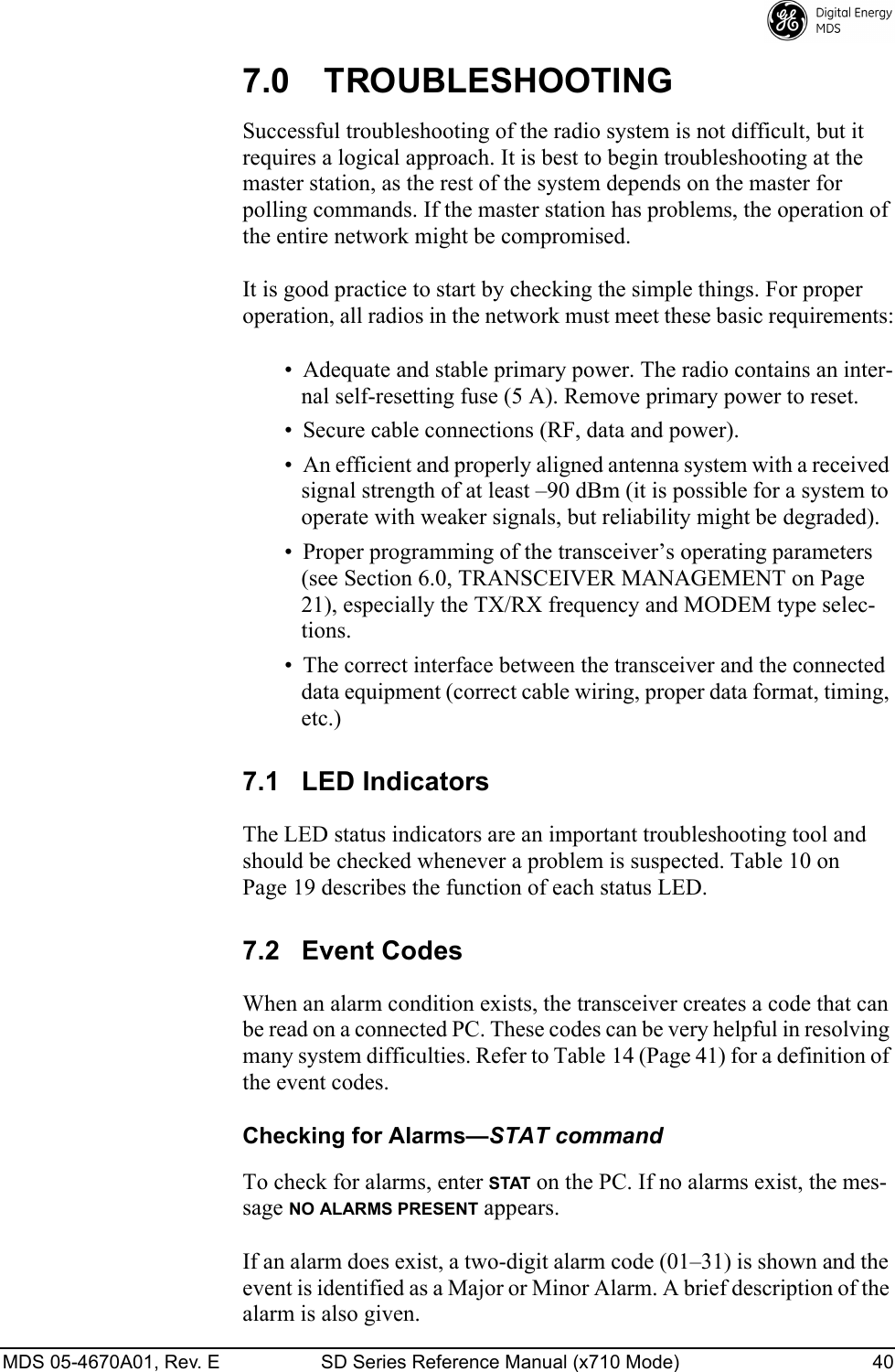
![MDS 05-4670A01, Rev. E SD Series Reference Manual (x710 Mode) 21 3. Press the key several times at half-second intervals to choose and select the correct baud rate. This will result in the > prompt.Invisible place holderFigure 17. PC Connection to TransceiverNOTE: TX and RX frequencies might not be set when the radio isshipped from the factory, depending on ordering options. Iffrequencies have not been set, the PWR LED will flash, indi-cating an alarm condition. The alarm will clear after thefrequencies are set. In all cases, users should verify that thefrequencies are properly set in accordance with the stationlicense.6.0 TRANSCEIVER MANAGEMENTTo perform transceiver management, connect a PC as described in Section 5.1, Initial Startup & Checkout and obtain the > prompt.6.1 Software CommandsTable 11 is a reference chart of software commands for the transceiver. Programmable information is shown in brackets [ ] following the com-mand name. See Section 6.2, Detailed Command Descriptions (Page 21) for detailed command descriptions.Entering CommandsTo enter a command, type the command, followed by . For pro-gramming commands, the command is followed by and the appropriate information or values, then .Table 11. Command Summary Command name Function AK Details Page 25 The Authorization Key and a list of authorized features. ALARM Details Page 25 Read current operating condition of radio. AMASK [0000 0000–FFFF FFFF] Details Page 25Set/display hex code identifying which events trigger an alarm.ENTERPC Running Terminal SessionTransceiverDB-9M to COM1 PortENTERSPACEENTER](https://usermanual.wiki/GE-MDS/DS-SD4-1/User-Guide-2653332-Page-31.png)
![22 SD Series Reference Manual (x710 Mode) MDS 05-4670A01, Rev. E ASENSE [HI, LO] Details Page 25Set/display the state of the alarm output signal to ACTIVE HI or ACTIVE LO. AUDIO [ON, OFF] Details Page 26Set/display the receive audio monitor mode for modems. BAUD [xxxxx abc] Details Page 26Set/display the DATA INTERFACE data rate and format. BIN [DATA, CLEAR] Details Page 26Display or clear data counters. BOOT Details Page 26 Used to initiate a software reboot. BUFF [ON, OFF] Details Page 26Enables or disables the internal radio data buffer. CKEY [ON–OFF] Details Page 27Enables or disables the continuously keyed mode. Note: Remotes cannot receive when keyed. CTS [0–255] Details Page 27Set/display the Clear-to-Send delay in seconds. CTSHOLD [0–60000] Details Page 27Set/display Clear-to-Send hold delay. DATAKEY [ON, OFF] Details Page 28Enables or Disables key-on-data mode(ON = key-on-data or RTS, OFF = key-on-RTS). DEV Details Page 28 Set/display modem control deviation. DEVICE [DCE, CTS KEY] Details Page 28Set/display device mode. DKEY Details Page 28 Dekey the radio (transmitter OFF). This is generally a radio test command. DLINK [ON/OFF/xxxx] Details Page 28Configures local diagnostic link protocol. DTYPE [NODE/ROOT] Details Page 29(diagnostics) Sets up a radio as a root or node radio. DUMP Details Page 29 Display all programmable settings. EMP [ON/OFF] Details Page 29Set/display TX audio pre-emphasis for analog mode. ETHADDR Details Page 29 Displays Ethernet MAC address (non-configurable). FORCEALARM [ON or OFF] Details Page 29Generates a test alarm for 10 sec. FORCEDCD [ON or OFF] Details Page 29Forces Data Carrier Detect (DCD) to always be asserted. HELP Details Page 29 Shows available commands. INIT Details Page 30 Set radio parameters to factory defaults for the radio outside the P-20 Protected Network Chassis. INIT [SDx] Details Page 30 Configure radio for use outside of the Protected Network Chassis (SDxP). Restores certain transceiver defaults changed by the INIT P-20 command.Table 11. Command Summary (Continued)Command name Function](https://usermanual.wiki/GE-MDS/DS-SD4-1/User-Guide-2653332-Page-32.png)
![MDS 05-4670A01, Rev. E SD Series Reference Manual (x710 Mode) 23 INIT [P-20] Details Page 30 Configure radio for service within a P-20 Protected Network Chassis. IPCONFIG Details Page 31 Ethernet interface configuration. KEY Details Page 31 Key the radio (transmitter ON). This is generally a radio test command. MENU Details Page 31 Activates the radio’s menu-based program (if supported). MODEL1 Details Page 31 Shows configuration order entry string associated with the radio. Programmed at the factory. MODEL2 Details Page 31 Shows an identifier string associated with the radio’s hardware bill of materials and revision. Programmed at the factory. MODEM [xxxx] Details Page 31Set the modem characteristics of the radio. OWM [XXX...] Details Page 33Set/display the owner’s message. OWN [XXX...] Details Page 33Set/display the owner’s name. PORT [RS232, RS485] Details Page 34Set/display COM2 data port interface settings. PTT [0–255] Details Page 34Set/display the Push-to-Talk delay in milliseconds. PTTSIG [OFF, LOW, HI] Details Page 34Set/display push-to-talk configuration. PWR [20–37] Details Page 34Set/display the transmit power setting. RESTORECONFIG Details Page 34Restores a saved user configuration. RESTOREDEFAULTS Details Page 34This command restores the original factory configuration. RMODE [X710, TRANSPARENT, PACKET, CMAC, HELP] Details Page 34Allows the reconfiguration of the SD operating mode. RSSI Details Page 34 Display the Received Signal Strength Indication. RTSKEY [ON, OFF] Details Page 35Set/display how the radio responds to RTS keying. Default is RTSKEY OFF, to prevent undesired keying of the transmitter when RTS is raised by a terminal program. RTU [ON/OFF/0-80] Details Page 35Re-enables or disables the radio’s internal RTU simulator and sets the RTU address. RX [xxx.xxxx] Details Page 35Set/display receiver frequency. RXATTN [ON or OFF] Details Page 35Enables or disables receive attenuation. RXLEVEL [–20 to 0] Details Page 35Set/display the receive audio input level.Table 11. Command Summary (Continued)Command name Function](https://usermanual.wiki/GE-MDS/DS-SD4-1/User-Guide-2653332-Page-33.png)
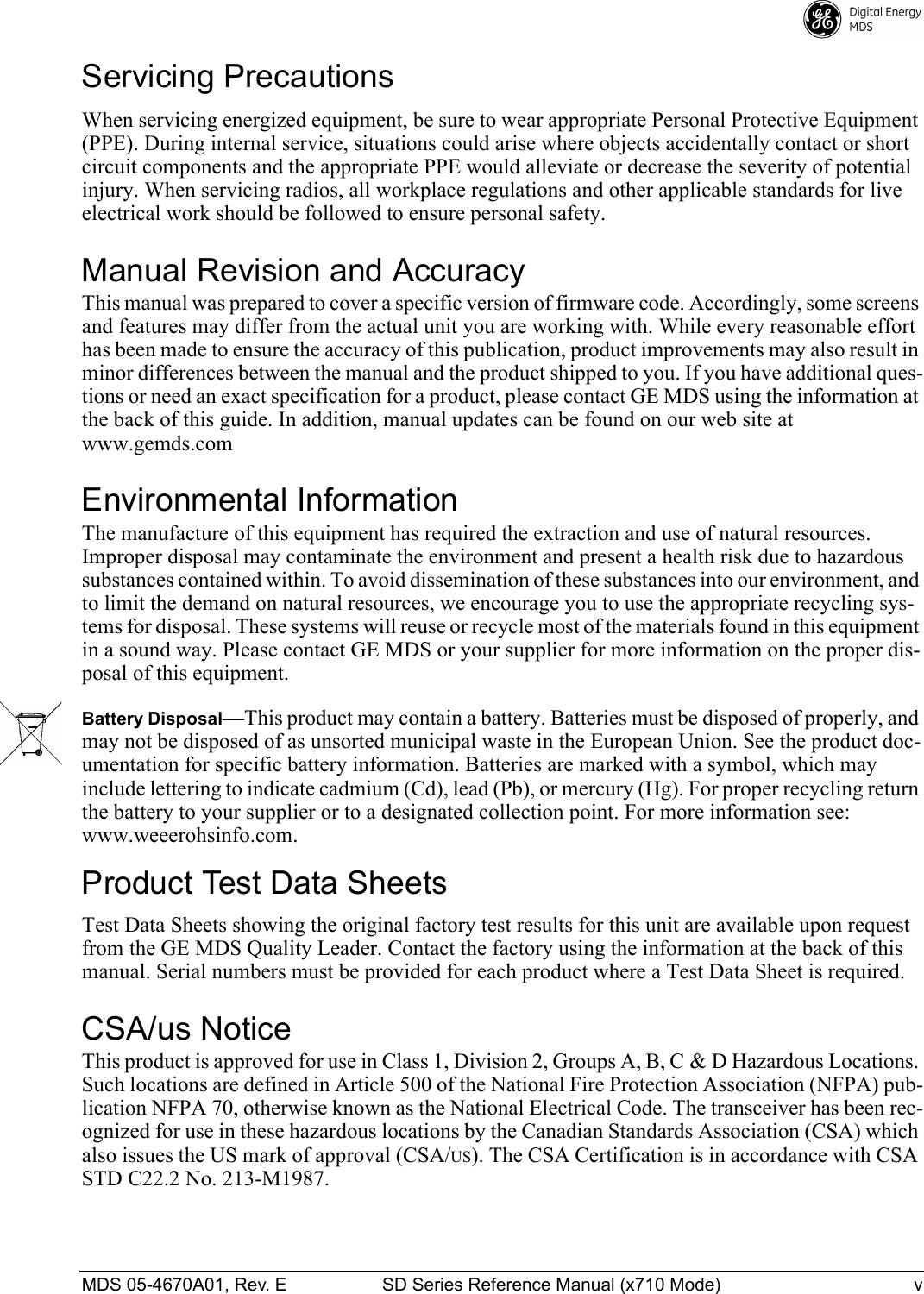
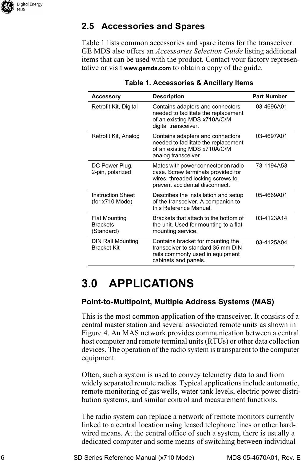
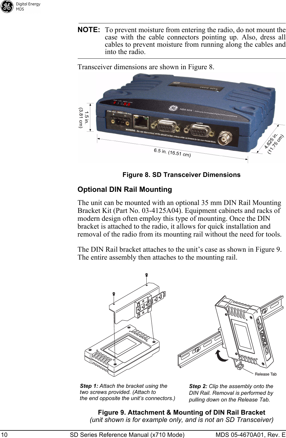
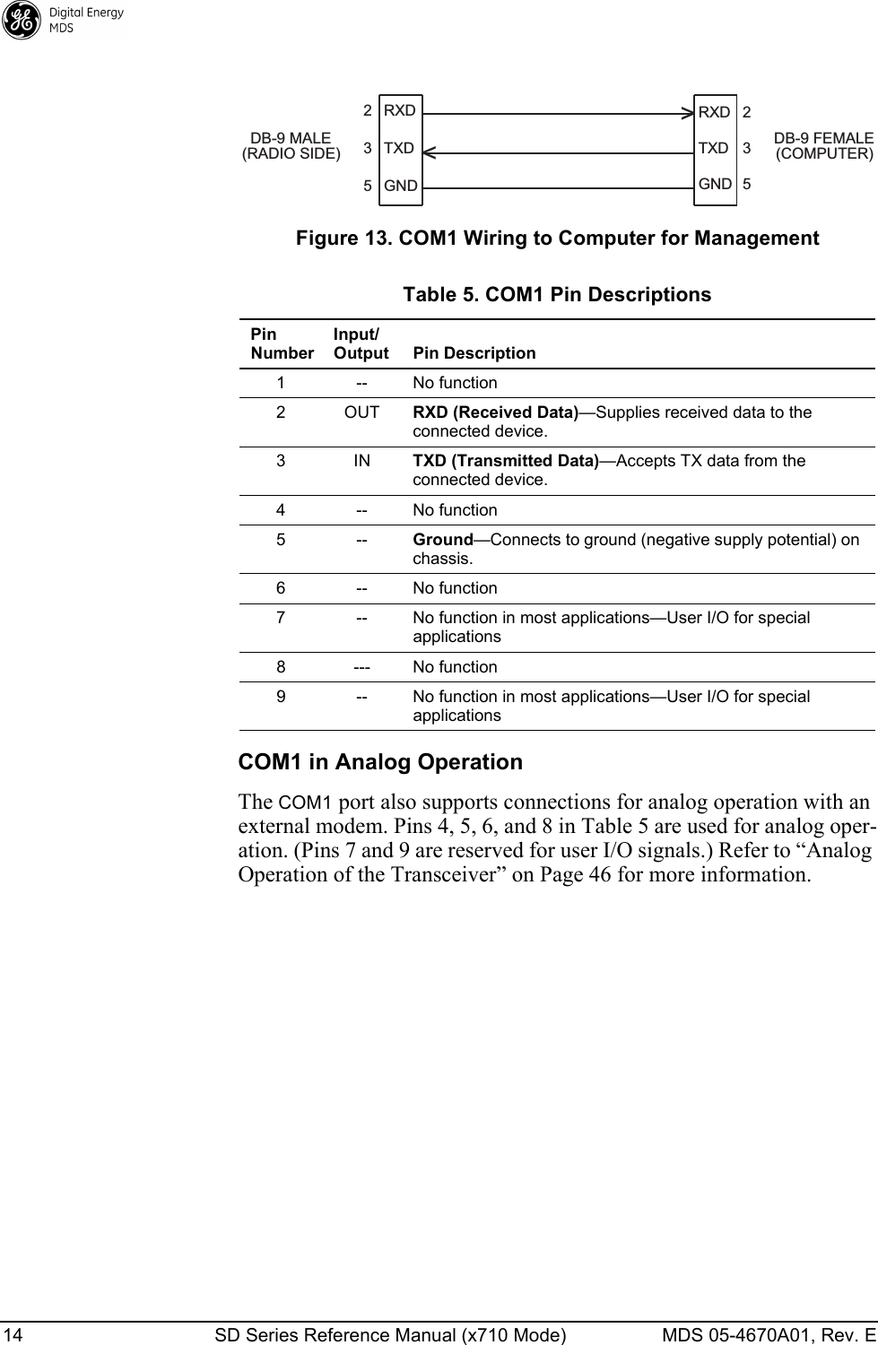
![24 SD Series Reference Manual (x710 Mode) MDS 05-4670A01, Rev. E 6.2 Detailed Command DescriptionsThe only critical commands for most applications are transmit and receive frequencies (TX xxx.xxxx, RX xxx.xxxx) and Modem configuration (MODEM xxxx) settings. However, proper use of the additional commands allows you to tailor the transceiver for a specific use, or conduct basic diagnostics on the radio. This section provides detailed information for the user commands previously listed in Table 11 (Page 21). RXTOL [NORMAL or CUSTOM] Details Page 36Set/display the custom receive tolerance to accommodate issues experienced with some x790 masters. RXTOT [NONE, 1-1440] Details Page 36Set/display the value of the receive time-out timer. SAVECONFIG Details Page 36Saves a user configuration. SCD [0-255] Details Page 36Set/display the Soft-Carrier Dekey delay in milliseconds. SER Details Page 36 Display the radio serial number. SHOW [DC, PWR] Details Page 36Display the DC voltages and transmit power level. SNR Details Page 36 Signal-to-Noise Ratio, expressed in dB. SPECTRUM [xxx.xx] Details Page 37Display the transceiver’s built-in spectrum analyzer, where xxx.xx denotes center frequency. SQUELCH [AUTO, BYPASSED] Details Page 37Set/display analog squelch bypass. SREV Details Page 37 Display the Software Revision Level. STAT Details Page 38 Display radio status and alarms. SWC [ON, OFF] Details Page 38Switched Carrier configuration. TFTP Details Page 38 Set/display all TFTP settings. TEMP Details Page 38 Display the internal temperature of the radio in degrees C. TOT [1-255, ON, OFF] Details Page 39Set/display the Time-out Timer delay in seconds. TX [xxx.xxxx] Details Page 39Set/display the transmit frequency. TXLEVEL [–20 to 0, AUTO] Details Page 39Set/display the transmit audio input level. UNIT [10000...65000] Details Page 39Set/display the transceiver’s unit address. UPTIME Details Page 39 Displays time since last system reboot. VERSION Details Page 39 Displays firmware package information.Table 11. Command Summary (Continued)Command name Function](https://usermanual.wiki/GE-MDS/DS-SD4-1/User-Guide-2653332-Page-34.png)
![MDS 05-4670A01, Rev. E SD Series Reference Manual (x710 Mode) 25 In many cases, the commands shown here can be used in two ways:• Type only the command name to view the currently programmed data. • Set or change the existing data by typing the command, followed by a space, and then the desired entry. In the list below, allowable programming variables, if any, are shown in brackets following the command name.Authorization KeyAKThe transceiver’s feature set may be expanded (if all features are not currently enabled) by entering a new authorization key, which can be purchased from GE MDS. Contact the factory to obtain a new Authori-zation Key.ALARMAlarm SummaryThe ALARM command displays a summary of the radio’s current oper-ating condition. An eight-digit code is presented which can be decoded as described in “Major Alarms vs. Minor Alarms” on Page 41.AMASK [0000 0000–FFFF FFFF]Alarm MaskThe AMASK command displays or sets which events cause an alarm output signal to be active. Normally, the mask is FFFF FFFF, meaning that any of the 32 possible events will activate the alarm output signal.Entering the AMASK command alone displays the current setting of alarm events in hexadecimal format.Entering the AMASK command followed by an eight-digit hexadecimal number reprograms the specified events to trigger an alarm.The eight-digit hexadecimal number used as the command parameter specifies 0 to 32 events that can trigger the external alarm output. (See Table 14 on Page 41 for a list of events.) The hex value for the mask cor-responds to the hex value for the STAT command (Page 38). Each bit that is a ‘1’ identifies an alarm condition that can trigger the external output. For more information on configuring the alarm response, contact GE MDS.ASENSE [HI, LO]Alarm SenseThe ASENSE command sets or displays the sense of the alarm output at Pin 6 of the COM2 port.Entering the ASENSE command alone shows whether the alarm output is active high or low. Entering the ASENSE command followed by HI or LO resets the alarm output to active high or low.](https://usermanual.wiki/GE-MDS/DS-SD4-1/User-Guide-2653332-Page-35.png)
![26 SD Series Reference Manual (x710 Mode) MDS 05-4670A01, Rev. E AUDIO [ON, OFF]Audio Monitor/Orderwire StatusUsed to set or display Audio Monitor/Orderwire functionality (on or off). If AUDIO ON is selected, the radio’s transmit functionality will switch to analog whenever PTT is asserted.BAUD [xxxxx abc]Data Interface Port Baud RateThis command sets (or displays) the communication attributes for the DATA INTERFACE port (COM2). It has no effect on the COM1 manage-ment port.The first parameter (xxxxx) is baud rate. Baud rate is specified in bits-per-second (bps) and must be one of the following speeds: 300, 1200, 2400, 4800, 9600, 19200, 38400, 57600, or 115200 bps.The second parameter of the BAUD command (abc) is a three-character block indicating how the data is encoded:a= Data bits (7 or 8)b= Parity (N for None, O for Odd, E for Even)c = Stop bits (1 or 2)The factory default setting is 9600 baud, 8 data bits, no parity, 1 stop bit (Example: 9600 8N1).BIN [DATA, CLEAR]Data CountersUsed to display or clear the data counters. Use BIN DATA to display. Use BIN CLEAR to clear the counters.BOOTSoftware RebootUsed to initiate a software reboot. Use BOOT alone to reboot the cur-rently running firmware image. Use BOOT 1, BOOT 2, or BOOT OTHER to reboot to a specific firmware image.BUFF [ON, OFF]RX Data BufferThis command sets or displays the received data handling mode of the radio. The command parameter is either ON or OFF. The default is ON. The setting of this parameter affects the timing of how received RF data is sent from the DATA INTERFACE connector. Outgoing (transmitted) data is not affected by this setting.If data buffering is OFF, the radio operates with the lowest possible average latency. Data bytes are sent from the DATA INTERFACE port as soon as an incoming RF data frame is disassembled. Average and typ-ical latency will be minimized, but idle character gaps may be intro-duced into the outgoing data flow.](https://usermanual.wiki/GE-MDS/DS-SD4-1/User-Guide-2653332-Page-36.png)
![MDS 05-4670A01, Rev. E SD Series Reference Manual (x710 Mode) 27 If data buffering is ON, the radio operates in seamless mode. Data bytes are sent over the air as quickly as possible, but the receiver buffers (stores) the data until enough bytes have arrived to cover worst-case gaps in transmission. This mode of operation is required for protocols such as MODBUS™ that do not allow gaps in their data transmission.NOTE: Seamless mode (BUFF ON) is intended only for applicationswhere the transmitter’s baud rate is greater than or equal to thereceiver’s baud rate. Enforcement of this rule is the user’sresponsibility.CKEY [ON–OFF]Key TX ContinuouslyThe CKEY command enables or disables the continuously-keyed func-tion of the radio. When CKEY is set to ON, the radio is continuously keyed and the Timeout Timer is disabled.CTS [0–255]Clear-to-Send TimeThe CTS (clear-to-send) command selects or displays the timer value associated with the CTS line response. The command parameter ranges from 0 to 255 milliseconds.For DCE operation, the timer specifies how long to wait after the RTS line goes high, before the radio asserts CTS and the DTE can transmit the data. A CTS value of zero keys the radio and asserts the CTS line immediately after the RTS line goes high.For CTS Key operation (see DEVICE command), the timer specifies how long to wait after asserting the CTS, before sending data from the DATA INTERFACE port. A timer value of zero means that data will be sent from the data port without imposing a key-up delay. (Other delays might be present based on selected radio operating parameters.)CTSHOLD [0–60000]Clear-to-Send Hold TimeUsed in DEVICE CTS KEY mode, this command sets the amount of time in milliseconds that CTS remains present after transmission of the last character from the RXD pin of the DATA port. This “hold time” can be used to prevent squelch tail data corruption when communicating with other radios.The CTSHOLD setting can range from 0 to 60000 ms (60 seconds). The default value is 0, which means that CTS will drop immediately after the last character is transmitted. If the command is entered when the radio is in DEVICE DCE mode, the response CTSHOLD N/A is shown.](https://usermanual.wiki/GE-MDS/DS-SD4-1/User-Guide-2653332-Page-37.png)
![28 SD Series Reference Manual (x710 Mode) MDS 05-4670A01, Rev. E DATAKEY [ON, OFF]Key on Data ActivityThe DATAKEY command enables or disables the ability of the radio to key the transmitter as data is received at the DATA INTERFACE connector. Asserting RTS keys the radio regardless of this command setting.If DATAKEY is set to ON, the radio will key when a full data-character is received at the transceiver’s DATA INTERFACE connector. If DATAKEY is set to OFF, the radio needs to be keyed by asserting RTS.DEVModem DeviationDisplays modem control deviation in Hertz (Hz). This is a read-only command, and cannot be changed in the field.DEVICE [DCE, CTS KEY]Data Device ModeThe DEVICE command controls or displays the device behavior of the radio. The command parameter is either DCE or CTS KEY.In DCE mode (the default setting), CTS will go high following RTS, sub-ject to the CTS programmable delay time. If the DATAKEY command is set to ON, keying can be stimulated by the input of characters at the data port. Hardware flow control is implemented by signaling the CTS line if data arrives faster than it can be buffered and transmitted.In CTS KEY mode, the SD is assumed to be controlling another radio. The SD will still key based on the RTS line, but the CTS line is used as a key-line control for the other radio. CTS is asserted immediately following the receipt of RF data, but data will not be sent out the DATA INTERFACE port until after the CTS programmable delay time has expired. (This gives the other radio time to key.)DKEYUnkey TransmitterThis command deactivates the transmitter after it has been keyed with the KEY command.DLINK [ON/OFF/xxxx]Diagnostic LinkUse this command to configure the local diagnostic link protocol used in network-wide diagnostics.Entering DLINK ON enables the diagnostic link. Entering DLINK OFF dis-ables the diagnostic link. To change the diagnostic link, enter DLINK followed by one of the fol-lowing baud rates: 1200, 2400, 4800, 9600, 19200 (default), 38400, 57600, 115200.](https://usermanual.wiki/GE-MDS/DS-SD4-1/User-Guide-2653332-Page-38.png)
![MDS 05-4670A01, Rev. E SD Series Reference Manual (x710 Mode) 29 NOTE: The radio is configured by default to be in DLINK mode. TheCOM1 port automatically determines the connected baud rate(within the range of 1200–115200 bps). Enter a series ofReturn Key presses about a half second apart until the > promptappears. This indicates that the radio is ready to receivecommands.DTYPE [NODE/ROOT]Unit’s Diagnostics TypeThis command establishes the local radio as a root radio or node radio for network-wide diagnostics. Entering DTYPE NODE configures the radio as a node radio. Entering DTYPE ROOT configures the radio as a root radio. Entering the DTYPE command alone displays the current setting.DUMPRead Current Unit ProfileThis command causes all of the programmed settings to be displayed.EMP [ON/OFF]Modem TX Audio Pre-EmphasisThis command displays or sets the TX pre-emphasis and RX De-Emphasis when the radio is operating with the analog mode and the radio’s MODEM is turned off (MODEM NONE). It should be set to match the other radios in the system. The use of pre- and de-emphasis can help reduce the detrimental influence of high frequency audio noise.ETHADDREthernet AddressDisplays programmed Ethernet MAC address (set at the factory).FORCEALARM [ON or OFF]Force AlarmGenerates a test alarm for 10 sec. Use to test alarm outputs and switch-over in redundant systems.FORCEDCD [ON or OFF]Force DCDForces Data Carrier Detect (DCD) to always be asserted. Use when con-necting to equipment that requires a constant DCD indication.HELPUser HelpShow available commands.](https://usermanual.wiki/GE-MDS/DS-SD4-1/User-Guide-2653332-Page-39.png)
Initialization (for standalone radio)This command sets the transceiver for “normal” operation outside the P-20 chassis by setting the following parameters to the values shown below:ASENSE ACTIVE HIAMASK FFFF FFFF (assert alarm output on all alarms)RXTOT NONE (receive time-out timer disabled)Use this command to restore these three parameters to the standard transceiver defaults if it was previously used in a P-20 package.INIT [P-20]Initialization for P-20 ImplementationThis command sets the transceiver for service inside a P-20 redundant chassis by setting the following parameters to the values shown below:ASENSE ACTIVE LOAMASK FFFF 0000 (trigger on major alarms)RXTOT 20 (20 minute receive time-out timer)](https://usermanual.wiki/GE-MDS/DS-SD4-1/User-Guide-2653332-Page-40.png)
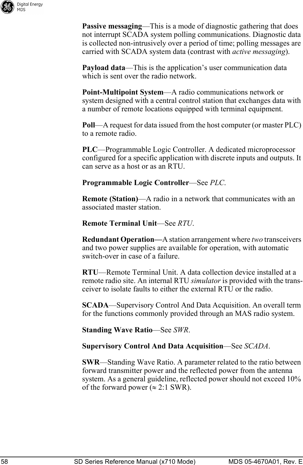
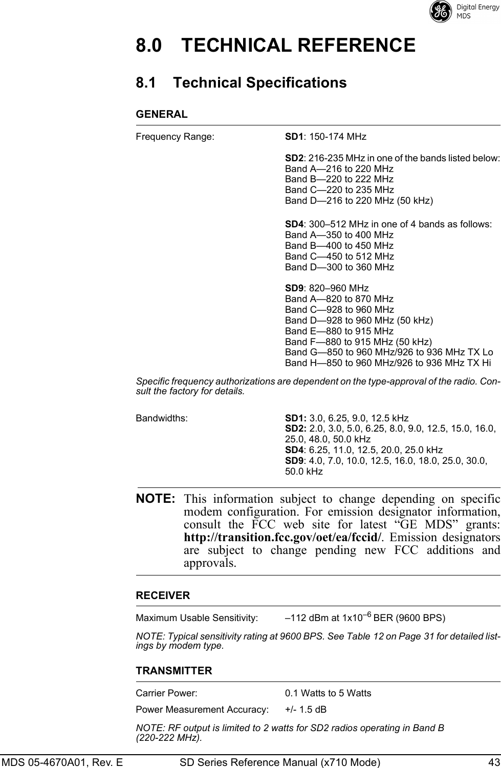
![MDS 05-4670A01, Rev. E SD Series Reference Manual (x710 Mode) 31 IPCONFIGEthernet ConfigurationEthernet interface configuration. This command is used to display or change the configuration of the Ethernet interface. The command can be used in several ways:•IPCONFIG alone displays all current network settings.•IPCONFIG DHCP [ON/OFF] is used to switch between DHCP and static addressing.•IPCONFIG IP [ipaddr] is used to set a static IP address.•IPCONFIG NET [netmask] and IPCONFIG GW [Gateway] are used to set subnet mask and gateway, respectively.KEYTX KeyThis command activates the transmitter. See also the DKEY command.MENUMenu ActivateActivates the menu-based program within the transceiver (when sup-ported), used for reprogramming the unit’s firmware.MODEL1Displays the factory software configuration of the radio.MODEL2Displays the hardware configuration bill of material identifier.Model Number InformationSee Table 11 on Page 21 for information on these pre-programmed fields.MODEM [xxxx]Analog/Digital Modem SelectionThis command selects the radio’s modem characteristics. For digital operation enter MODEM xxxx, where xxxx equals the modem selection of the radio. Table 12 shows the supported modem types.NOTE:For compatibility with an existing MDS x710 system, make sure to select the matching MODEM type. See Table 11.Table 12. Modem Selection vs. Speed, Bandwidth & SensitivityModem Type SelectionOver-the-air Speed (bps)B/W (kHz) ApproximateSensitivity5Modem 960019600 12.5 -112 dBmModem 48001, 24800 12.5 -112 dBmModem 32001, 33200 5.00 -108 dBmModem 9600M1, 29600 12.5 -106 dBm](https://usermanual.wiki/GE-MDS/DS-SD4-1/User-Guide-2653332-Page-41.png)
![32 SD Series Reference Manual (x710 Mode) MDS 05-4670A01, Rev. E 1) For MDS x710-compatible operation.2) For ETSI compliance.3) 3200 bps not applicable to SD4.4) Only available for SD2 and SD9 units with wide bandwidth hardware option.Sensitivity is -104 dBm for SD2 and -100 dBm for SD9.5) SD1 sensitivity may be up to 2 dB less, due to MDS 1710 interoperability constraints.For analog operation with an external modem, enter NONE for this parameter. When the MODEM is set to NONE, the analog TX Input and RX Audio outputs of the DATA INTERFACE are used to interface with the connected external modem, and digital operation is disabled. These levels must be set to complement the audio signal level requirements of the external modem. See “RXLEVEL [–20 to 0]” on page 35 and “TXLEVEL [–20 to 0, AUTO]” on Page 39 for details on setting these levels.Modem 4800F 4800 6.25 -108 dBmModem 9600B19600 12.5 -106 dBmModem 4800B14800 12.5 -110 dBmModem BELL11200 12.5 -110 dBmModem V23 1200 12.5 -110 dBmModem 19200N 19200 12.5 -100 dBmModem 19200E219200 12.5 -96 dBmModem 9600N 9600 6.25 -98 dBmModem 19200 19200 25.0 -105 dBmModem 38400N 38400 25.0 -99 dBmModem 65000465000 50.0 -102 dBmModem NONE For analog operation with an external modem. See text.Table 12. Modem Selection vs. Speed, Bandwidth & SensitivityModem Type SelectionOver-the-air Speed (bps)B/W (kHz) ApproximateSensitivity5](https://usermanual.wiki/GE-MDS/DS-SD4-1/User-Guide-2653332-Page-42.png)
![MDS 05-4670A01, Rev. E SD Series Reference Manual (x710 Mode) 33 When the transceiver is used to replace an existing MDS x710 radio, it is important to verify that the modem selection is compatible with the unit replaced. Table 13 lists SD modem type selections and the compat-ible x710 models they can be used with.OWM [XXX...]Owner’s MessageThis is a command to show or program an owner’s message. To pro-gram the owner’s message, type OWM then the message, followed by .To show the owner’s message, type OWM then . The owner’s message appears on the display.OWN [XXX...]Owner’s NameThis is a command to show or program an owner’s name. To program the owner’s name, type OWN then the name, followed by .To show the owner’s name, type OWN then . The owner’s name appears on the display.Table 13. Modem Compatibility with MDS x710 RadiosSD Modem Type SelectionCompatible with MDS x710 ModelsModem 9600 2710A, 4710A, 9710AModem 4800 4710E, 9710EModem 3200 2710DModem 9600M 4710M, 9710MModem 4800F --Modem 9600B 4710B, 9710BModem 4800B 4710B, 9710BModem BELL 4710B, 9710BModem V23 --Modem 19200N --Modem 19200E --Modem 9600N --Modem 19200 2710C, 4710C, 9710CModem 38400N --Modem 65000 --Modem NONE x710A / x710C / x710E “modem none”MPT1411 x710M “modem none”ENTERENTERENTERENTER](https://usermanual.wiki/GE-MDS/DS-SD4-1/User-Guide-2653332-Page-43.png)
![34 SD Series Reference Manual (x710 Mode) MDS 05-4670A01, Rev. E PORT [RS232, RS485]COM2 SettingsSet or show COM2 data port interface settings.Push-to-Talk DelayPTT [0–255]This command sets or shows the key-up delay in milliseconds.This timer specifies how long to wait after the radio receives a key signal, before actually keying the radio.Push-to-Talk ConfigurationPTTSIG [OFF, LOW, HI]Used to set or show the configuration of the push-to-talk signal. This signal is used for analog operation.TX RF Power Output LevelPWR [20–37]NOTE: This function might be restricted due to regulatory constraints.This command displays or sets the desired RF forward output power set-ting of the radio. The PWR command parameter is specified in dBm and can range from 20 through 37. The default setting is 37 dBm (5 watts). To read the actual (measured) power output of the radio, use the SHOW PWR command. A dBm-to-watts conversion chart is provided in Section 8.6 (Page 55).RESTORECONFIGRestore ConfigurationThis command restores a user configuration. Command is timed and aborts in 3 sec if no response is provided.RESTOREDEFAULTSRestore DefaultsThis command restores the original factory configuration. Command is timed and aborts in 3 sec if no response is provided.RMODE [X710, TRANSPARENT, PACKET, CMAC, HELP]Radio ModeAllows the reconfiguration of the SD operating mode. An “MS” radio model normally ships with x710 mode and provides the command inter-face documented in this manual. Changing to a mode other than x710 causes the radio to exit the x710 command emulation interface and prompt for a user login.RSSIReceived Signal Strength IndicatorThis command continuously displays the radio’s Received Signal Strength Indication (RSSI) in dBm, until you press the Enter key. Incoming signal strengths up to -60 dBm can be read.](https://usermanual.wiki/GE-MDS/DS-SD4-1/User-Guide-2653332-Page-44.png)
![MDS 05-4670A01, Rev. E SD Series Reference Manual (x710 Mode) 35 NOTE: The RSSI samples the incoming signal for one to two secondsbefore providing an average reading to the connected PC.RTSKEY [ON, OFF]RTS Keying BehaviorUsed to set/display how the radio responds to RTS keying. The default setting is RTSKEY OFF. RTSKEY ON causes the radio to respond to RTS by keying the transmitter. When RTSKEY OFF is selected, key-on-RTS is suppressed.NOTE: Terminal emulators such as HyperTerminal and Procommtypically initiate the RTS signal continuously upon the start ofa connection. When connected to the radio’s COM2 payloadport, this typically causes the transmitter to remain constantlykeyed. In such cases, RTSKEY OFF allows a terminal emulatorto be connected to the radio’s COM2 port without the need forspecial cables or a break-out box.RTU [ON/OFF/0-80]RTU EmulatorThis command enables or disables the radio’s internal RTU simulator, which runs with proprietary polling programs such as poll.exe and rsim.exe. The internal RTU simulator is available whenever a radio has diagnostics enabled. This command also sets the RTU address that the radio will respond to.The internal RTU can be used for testing system payload data or pseudo bit error rate testing. It can be helpful in isolating a problem to either the external RTU or the radio.RX [xxx.xxxx]Receive FrequencyThis command selects or shows the radio’s receive frequency in MHz. The frequency step size is 125 Hz.If the customer frequency has not been programmed at the factory, a default frequency will be programmed in the radio near the center of the frequency band. For a list of frequency bands per radio model, refer to “ Technical Specifications” on Page 43.RXATTN [ON or OFF]Receive AttenuationEnables or disables receive attenuation. Enable receive attenuation when a remote is in close proximity to a master (such as on a test bench).RXLEVEL [–20 to 0]RX Audio Output LevelThe RXLEVEL command selects or shows the desired receive audio output level. For more information, refer to the detailed description of analog operation beginning on Page 46.](https://usermanual.wiki/GE-MDS/DS-SD4-1/User-Guide-2653332-Page-45.png)
![36 SD Series Reference Manual (x710 Mode) MDS 05-4670A01, Rev. E RX ToleranceRXTOL [NORMAL or CUSTOM]The RXTOL command allows custom configuration of the receive toler-ance, to improve performance with legacy radios (x790, x310, and so on).RXTOT [NONE, 1-1440]Loss of RX Data Alarm TimeThe RXTOT command selects or shows the receive time-out timer value in minutes. This timer triggers an alarm (event 12) if data is not detected within the specified time.Entering the RXTOT command without a parameter shows the timer value in minutes. Entering the RXTOT command with a parameter ranging from 0 to 1440 resets the timer in minutes. (1440 minutes equals 24 hours.) Entering the RXTOT command with the parameter NONE disables the timer.SAVECONFIGSave ConfigurationSaves a user configuration. Command is timed and aborts in 3 sec if no response is provided.SCD [0-255]Soft-Carrier DekeyThis command shows or changes the soft-carrier dekey delay in milli-seconds.This timer specifies how long to wait after the removal of the keying signal before actually releasing the transmitter. A value of 0 millisec-onds will unkey the transmitter immediately after the removal of the keying signal.SERRadio Serial NumberThis command shows the radio’s serial number as recorded at the fac-tory (non-configurable).SHOW [DC, PWR]Show Power SettingsThe SHOW command shows different types of information based on the command variables. The different parameters are:•DC—Display DC input/output voltages•PWR—Display RF power outputSNRRX Signal-to-Noise RatioThis command continuously shows the signal-to-noise ratio of the received signal expressed in dB, until you press the Enter key. As used in this guide, the signal-to-noise measurement is based upon the signal level following equalization, for received frames.](https://usermanual.wiki/GE-MDS/DS-SD4-1/User-Guide-2653332-Page-46.png)
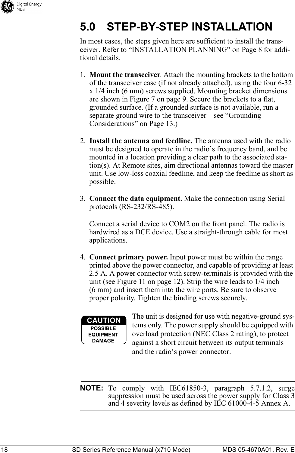
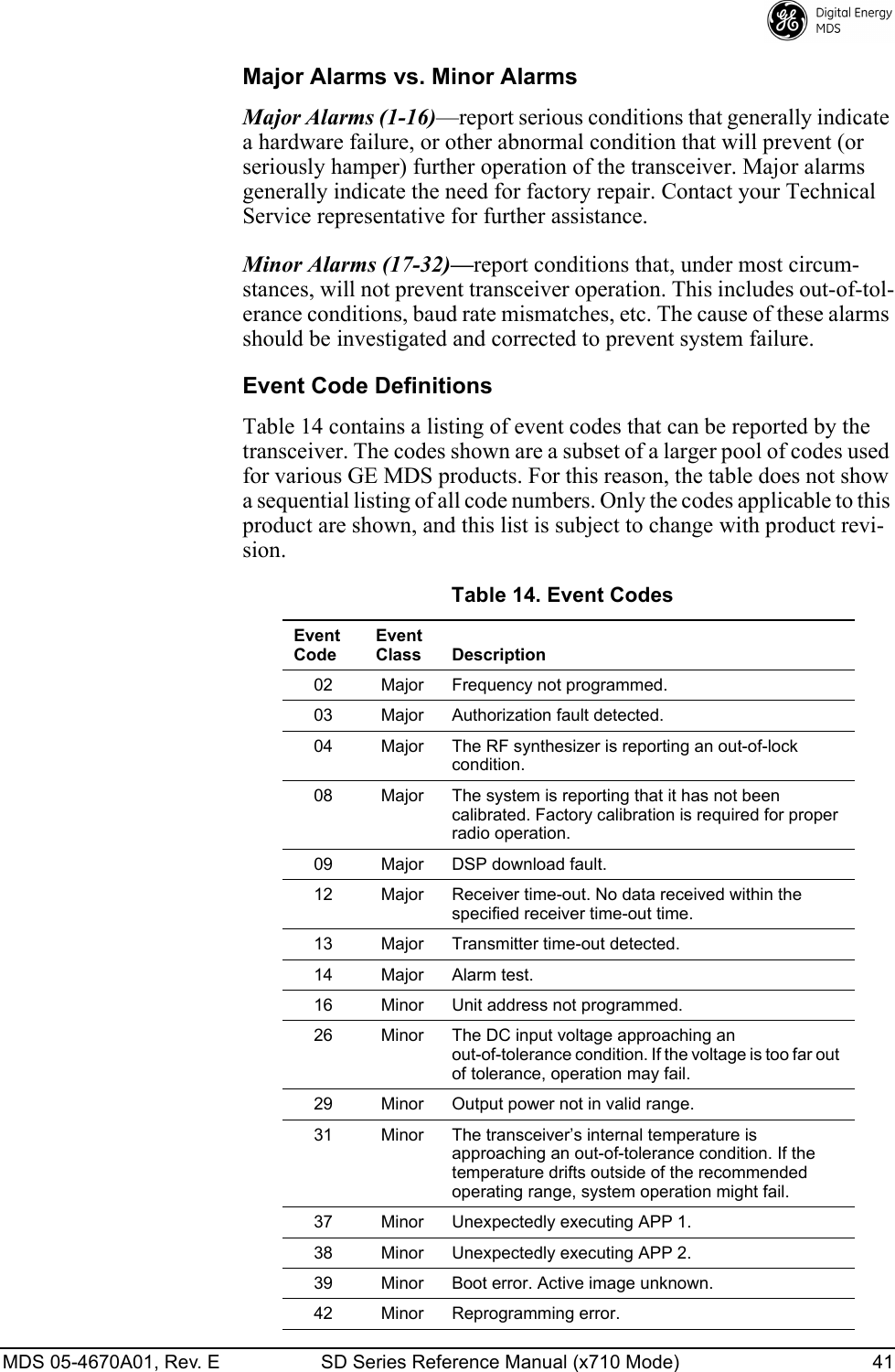
![MDS 05-4670A01, Rev. E SD Series Reference Manual (x710 Mode) 37 The SNR is an indication of the received signal quality. A value of 10 dB represents a very poor signal. A value of 24 dB represents a very good signal.When the SNR command is used, it causes the DIAG. port to enter an update mode, and the signal-to-noise ratio is updated and redisplayed every 2 seconds. The SNR continuously updates until the key is pressed.SPECTRUM [xxx.xx]Internal Spectrum Analyzer Activates the built-in spectrum analyzer tool (see Figure 18) that can be shown on a connected PC. This tool is helpful in diagnosing interference problems on or near your channel frequency.Access the spectrum analyzer by entering spectrum at the command prompt. A display appears showing detected signals on your current channel.Optionally, you can specify a frequency at the command prompt to view the surrounding spectrum of that frequency. To do this, enter spectrum xxx.xx, where xxx.xx is the frequency in MHz.A typical spectrum analyzer display is shown in Figure 18. The display creates a received signal strength indication (RSSI) vs. frequency plot for the fre-quency and surrounding signals. By analyzing the display, you can determine the presence of other signals near the transceiver’s operating frequency. This information can be helpful in troubleshooting interference problems.Invisible place holderFigure 18. Internal Spectrum Analyzer DisplaySQUELCH [AUTO, BYPASSED]Squelch OperationSet or show analog squelch bypass.SREVSoftware/Firmware Revision LevelThis command shows the software revision level of the transceiver firm-ware.ENTER](https://usermanual.wiki/GE-MDS/DS-SD4-1/User-Guide-2653332-Page-47.png)
![38 SD Series Reference Manual (x710 Mode) MDS 05-4670A01, Rev. E STATAlarm StatusThis command shows the current alarm status of the transceiver.If no alarms exist, the message NO ALARMS PRESENT appears.If an alarm does exist, a two-digit code (00–31) is displayed and the alarm is identified as “Major” or “Minor.” A brief description of the alarm code is also given.If more than one alarm exists, the word MORE appears at the bottom of the screen, and additional alarms are viewed by pressing the key. Detailed descriptions of event codes are provided in Table 14 on Page 41.SWC [ON, OFF]Switched CarrierHow you configure this command is based on whether or not the trans-ceiver is listening to a continuously keyed master. If the master is not continuously keyed, then the master is operating in switched carrier mode and the transceiver’s SWC setting should be ON. If the master is continuously keyed, the transceiver’s SWC setting should be OFF. For B modem operation only. SWC should be OFF for A modems.NOTE:SWC must be set to ON for switched carrier operation.TFTPTFTP SettingsUsed to set/show all TFTP settings for upgrading the radio’s firmware through the Ethernet port using TFTP transfer. The command can be used in several different ways:•TFTP HOST [ipaddr] sets the IP address of the TFTP server hosting the firmware.•TFTP FILE [filename] specifies the filename of the firmware to downloaded.•TFTP GET is used after the above commands to begin the TFTP transfer.•TFTP STATUS can be used to check on the progress of the down-load.TEMPInternal TemperatureThis command shows the internal temperature of the transceiver in degrees Celsius.ENTER](https://usermanual.wiki/GE-MDS/DS-SD4-1/User-Guide-2653332-Page-48.png)
![MDS 05-4670A01, Rev. E SD Series Reference Manual (x710 Mode) 39 TOT [1-255, ON, OFF]TX Timeout-TimerThis command sets or shows the transmitter Time-out Timer value (1–255 seconds), as well as the timer status (ON or OFF). If the timer is on, and the radio remains keyed for a longer duration than the TOT value, the transmitter is automatically unkeyed.When this happens, the radio must be commanded back to an unkeyed state before a new keying command is accepted. The default timer value is 30 seconds.TX [xxx.xxxx]TX FrequencyThis command selects or shows the radio’s transmit frequency in MHz. The frequency step size is 125 Hz.If the customer frequency has not been programmed at the factory, a default frequency will be programmed in the radio near the center of the frequency band.TXLEVEL [–20 to 0, AUTO]TX Audio Input LevelThe TXLEVEL command selects or shows the expected transmit audio input level from an external modem. For more information, refer to the detailed description of analog operation beginning on Page 46.For optimum performance, set this parameter to match the external modem level. For example TXLEVEL –10. TXLEVEL AUTO is also available (default setting: –10 dBm).UNIT [10000...65000]Unit AddressThe unit address is the radio’s unique identity for the network’s diag-nostic activities. The unit responds to a request for a diagnostics code broadcast by the Master Station to all Remotes in an MAS network, if its unit address matches the number broadcast. The default number is programmed by the factory to the last four digits of the radio’s serial number.UPTIMEUp TimeDisplays time since last system reboot.VERSIONFirmware VersionDisplays package version information for each firmware image.](https://usermanual.wiki/GE-MDS/DS-SD4-1/User-Guide-2653332-Page-49.png)
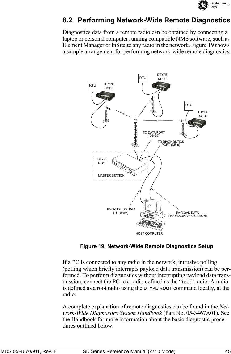
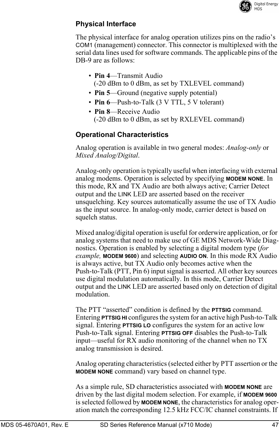
![MDS 05-4670A01, Rev. E SD Series Reference Manual (x710 Mode) 46 1. Program one radio in the network as the root radio by entering the DTYPE ROOT command at the radio.2. At the root radio, use the DLINK ON and DLINK [baud rate] commands to configure the diagnostic link protocol on the Management Port.3. Program all other radios in the network as nodes by entering the DTYPE NODE command at each radio.4. Use the DLINK ON and DLINK [baud rate] commands to configure the diagnostic link protocol on the Management Port of each node radio.5. Connect same-site radios using a null-modem cable at the radios’ diagnostic ports.6. Connect a PC running the management software to the root radio, or to one of the nodes, using the radio’s COM1 port. This PC can also be the PC used to collect payload data, as shown in Figure 19.7. Launch the diagnostic program at the PC.8.3 User-Programmable I/O Functions - PendingThe transceiver can be internally configured to provide three user I/O functions on the COM1 and COM2 data connectors. These signals are commonly used for RTU resetting or for analog input monitoring. Once the transceiver has been properly configured, these pins can be activated through compatible NMS software, such as Element Manager or InSite.The jumpering changes required to enable these functions are beyond the scope of this manual. Consult the factory for further information on enabling and using these I/O functions.8.4 Analog Operation of the TransceiverThe transceiver is designed for full digital modulation, while offering analog support to those systems that require it. Operation is compatible with the MDS x710 family of products, but some SD radio-specific command configuration and wiring might be necessary based on differ-ences in SD hardware. This section provides important information for using the radio in analog service.](https://usermanual.wiki/GE-MDS/DS-SD4-1/User-Guide-2653332-Page-56.png)