GIT G1XDDMN001 Scan Tool User Manual
G.I.T Co.,Ltd. Scan Tool
UserManual.wiki
>
GIT
>
G1XDDMN001 User Manual
User Manual
Navigation menu
Upload a User Manual
Namespaces
Wiki Guide
HTML
PDF
Info
Views
User Manual
Discussion / Help
Navigation
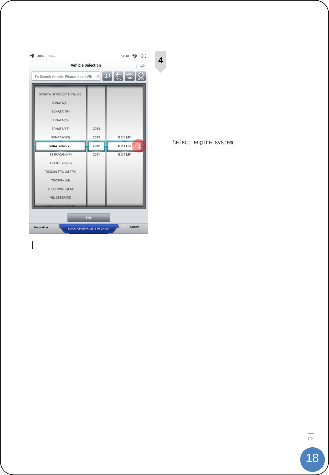
![21G | Disposal of Old Electrical and Electronic Equipment WEEE (Waste Electrical and Electronic Equipment) symbol shown in [Figure 1] is indicated on the back of the VCI main module, VMI main module, and Trigger module. Please follow the regulation guide for disposal of Waste Electrical and Electronic Equipment. Use caution disposing of the Trigger module; it contains a lithium battery. Users must follow the regulations when replacing or discarding this battery. Fig. 1. WEEE Symbol Disposal of Old Electrical & Electronic Equipment (Applicable in the European Union and other European countries with separate collection systems) This symbol on the product or on its packaging indicates that this product shall not be treated as household waste. Instead it shall be handed over to the applicable collection point for the recycling of electrical and electronic equipment. By ensuring this product is disposed of correctly, you will help prevent potential negative consequences for the environment and human health, which could otherwise be caused by inappropriate waste handling of this product. The recycling of materials will help to conserve natural resources. For more detailed information about recycling of this product, please contact your local city office, your household waste disposal service or the shop where you purchased the product.](https://usermanual.wiki/GIT/G1XDDMN001/User-Guide-2266366-Page-22.png)