GS Instech CC25K700 Cover4G25K User Manual
GS Instruments Co., Ltd. Cover4G25K
UserManual.wiki
>
GS Instech
>
CC25K700 User Manual
User manual
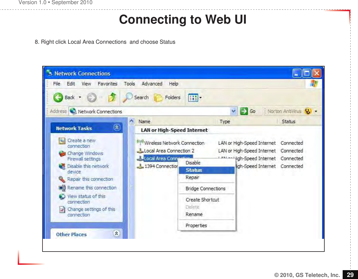
Navigation menu
Upload a User Manual
Namespaces
Wiki Guide
HTML
PDF
Info
Views
User Manual
Discussion / Help
Navigation
![Version 1.0 September 2010© 2010, GS Teletech, Inc. 11Coverage• Common Condition 1. System Output Power -> LTE : 0dBm/FA @ pilot 2. Mobile Input Power : -90dBm/FA @ pilot 3. Donor Antenna Gain -> LTE : 8dBi 4. Coverage Antenna -> Common : 2dBi• SUBURBAN 5. LTE : 1 channel -> 9dBm/total @ EIRP<Small Room>Path Loss = 32.44+20Log[Frequency]+20Log[Distance(km)]+Indoor Loss](https://usermanual.wiki/GS-Instech/CC25K700/User-Guide-1385027-Page-11.png)
![Version 1.0 September 2010© 2010, GS Teletech, Inc. 12Coverage• Common Condition 1. System Output Power -> LTE : 6dBm/FA @ pilot 2. Mobile Input Power : -90dBm/FA @ pilot 3. Donor Antenna Gain -> LTE : 8dBi 4. Coverage Antenna -> Common : 2dBi• SUBURBAN 5. LTE : 1 channel -> 15dBm/total @ EIRP<Small Room>Path Loss = 32.44+20Log[Frequency]+20Log[Distance(km)]+Indoor Loss](https://usermanual.wiki/GS-Instech/CC25K700/User-Guide-1385027-Page-12.png)