GasSecure AS GS01AA Wireless gas detector User Manual GasSecure GS01 Hardware Manual
GasSecure AS Wireless gas detector GasSecure GS01 Hardware Manual
UserManual.wiki
>
GasSecure AS
>
GS01AA User Manual
>
user manual
Contents
1.
Users Manual
2.
user manual
user manual
Navigation menu
Upload a User Manual
Namespaces
Wiki Guide
HTML
PDF
Info
Views
User Manual
Discussion / Help
Navigation
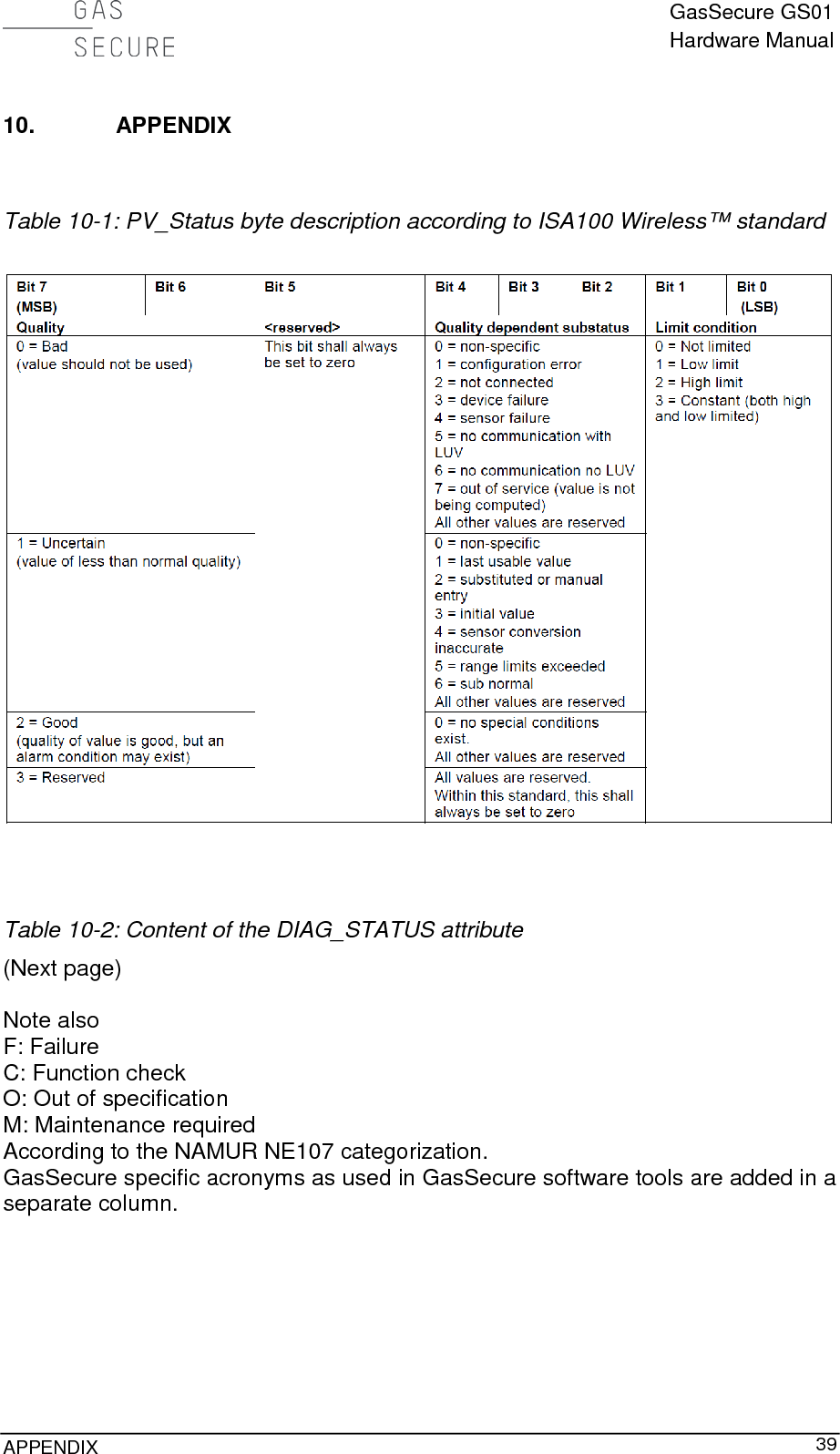
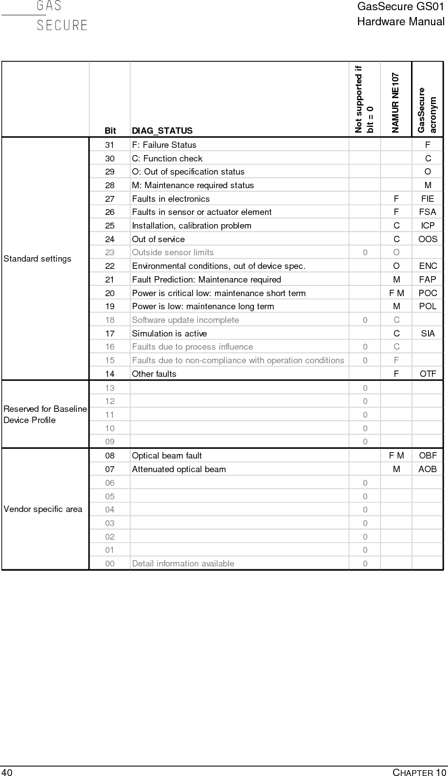
![GasSecure GS01 Hardware Manual IV FIGURES FIGURE 1-1: GS01 DETECTOR LAYOUT................................................................................................................ 6 FIGURE 1-2: GS01 DETECTOR WITH DIMENSIONS IN [MM] ................................................................................... 7 FIGURE 1-3: GS01-EA DETECTOR WITH DIMENSIONS IN [MM] ............................................................................ 8 FIGURE 1-4: GS01 MEASURING CELL DETAILS ..................................................................................................... 8 FIGURE 2-1: CORRECT POSITION OF THE WEATHER CAP AND LOCATION OF EARTH POINT. ................................. 10 FIGURE 2-2: GS01-EA LAYOUT WITH ANTENNA CONNECTIONS ........................................................................ 11 FIGURE 3-1: GS01 CONFIGURATOR ................................................................................................................... 17 FIGURE 5-1: BATTERY PACK WARNING LABEL ................................................................................................... 24 FIGURE 5-2: BATTERY PACK BOTTOM VIEW ...................................................................................................... 25 FIGURE 5-3: BATTERY PACK TOP AND BOTTOM ................................................................................................. 25 FIGURE 7-1: GS01 PRODUCT IDENTIFICATION PLATE ......................................................................................... 31 FIGURE 7-2: GS01-EA PRODUCT IDENTIFICATION PLATE .................................................................................. 32 FIGURE 7-3: GS01 PRODUCT IDENTIFICATION PLATE – FM APPROVED .............................................................. 32 FIGURE 7-4: GS01-EA PRODUCT IDENTIFICATION PLATE – FM APPROVED ....................................................... 32 FIGURE 7-5: FCC COMPLIANCE LABEL .............................................................................................................. 33 FIGURE 7-6: BATTERY PACK IDENTIFICATION LABEL (FM APPROVED VERSION TO THE RIGHT) ......................... 34 FIGURE 7-7: ANTENNA IDENTIFICATION LABEL (FM APPROVED VERSION TO THE RIGHT) .................................. 34 FIGURE 10-1: EU DECLARATION OF CONFORMITY FOR GS01 AND GS01-EA ................................................... 42 TABLES TABLE 2-1: PROPERTIES OF STANDARD ANTENNA CABLE FOR THE GS01-EA ................................................... 11 TABLE 3-1: ISA100 OBJECTS ............................................................................................................................ 13 TABLE 3-2: LEL VALUES IN [% VOL] ACCORDING TO IEC AND NIOSH ............................................................ 14 TABLE 3-3: PV GAS MEASUREMENT DATA INTEGRITY ...................................................................................... 15 TABLE 4-1: RECOMMENDED GAS CONCENTRATIONS FOR VALIDATION .............................................................. 21 TABLE 5-1: IMPORTANT SPARE PARTS AND ACCESSORIES FOR THE GS01 ......................................................... 22 TABLE 5-2: STATUS MESSAGES RETRIEVED FROM THE DIAG_STATUS ATTRIBUTE ............................................ 27 TABLE 7-1: LIST OF APPLICABLE STANDARDS FOR THE GS01 ............................................................................ 30 TABLE 8-1: PERFORMANCE CHARACTERISTICS FOR THE GS01.......................................................................... 35 TABLE 8-2: LEL VALUES IN [% VOL] ACCORDING TO IEC60079-20. ................................................................ 36 TABLE 8-3: CROSS SENSITIVITIES FOR A GS01 METHANE DETECTOR. ............................................................... 36 TABLE 8-4: CROSS SENSITIVITIES FOR A GS01 PROPANE DETECTOR. ................................................................ 36 TABLE 8-5: LEL VALUES IN [% VOL] ACCORDING TO NIOSH. .......................................................................... 36 TABLE 8-6: CROSS SENSITIVITIES FOR A GS01 METHANE DETECTOR. ............................................................... 37 TABLE 8-7: CROSS SENSITIVITIES FOR A GS01 PROPANE DETECTOR. ................................................................ 37 TABLE 10-1: PV_STATUS BYTE DESCRIPTION ACCORDING TO ISA100 WIRELESS™ STANDARD....................... 39 TABLE 10-2: CONTENT OF THE DIAG_STATUS ATTRIBUTE ............................................................................ 39](https://usermanual.wiki/GasSecure-AS/GS01AA.user-manual/User-Guide-3394610-Page-5.png)
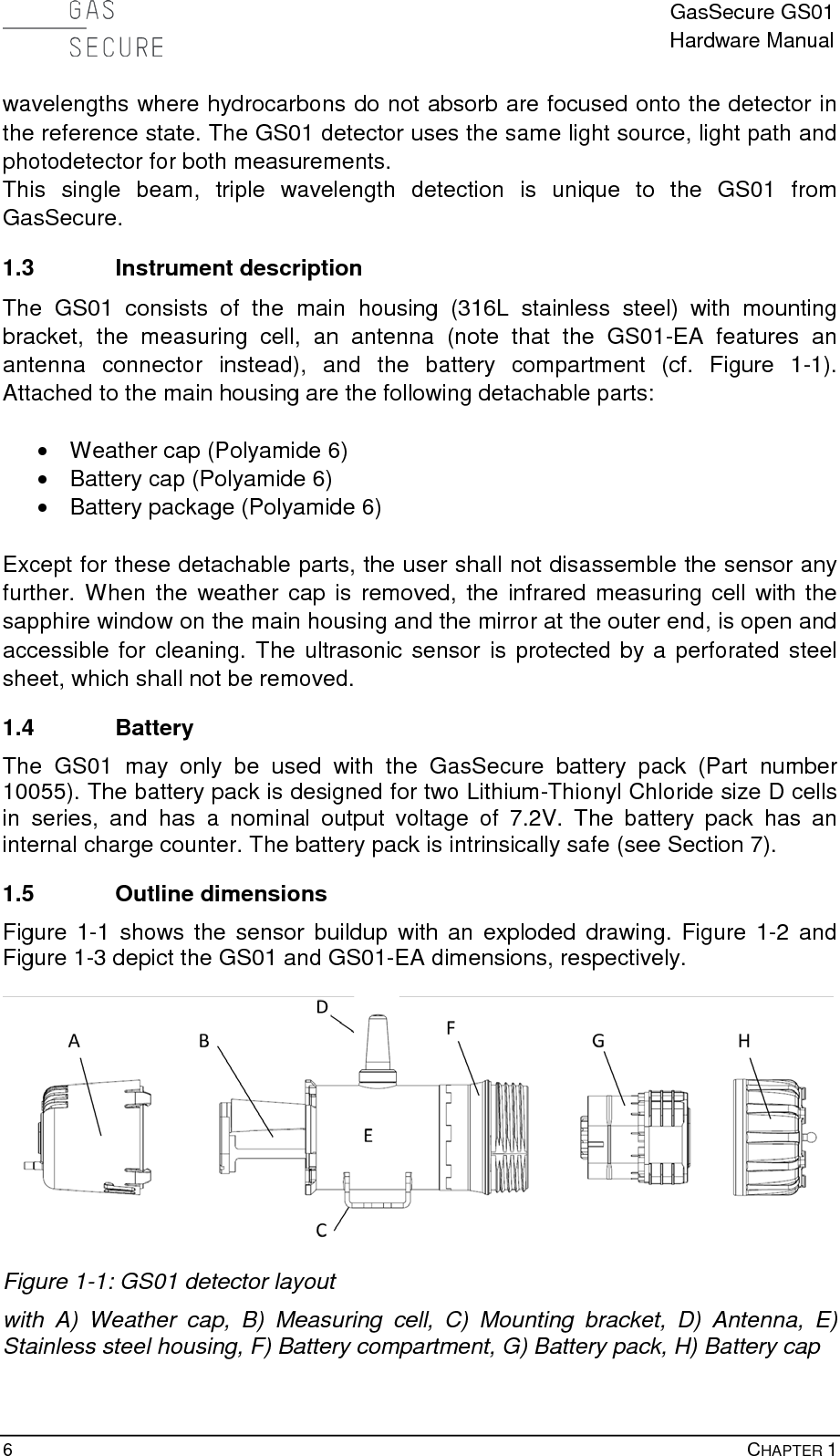
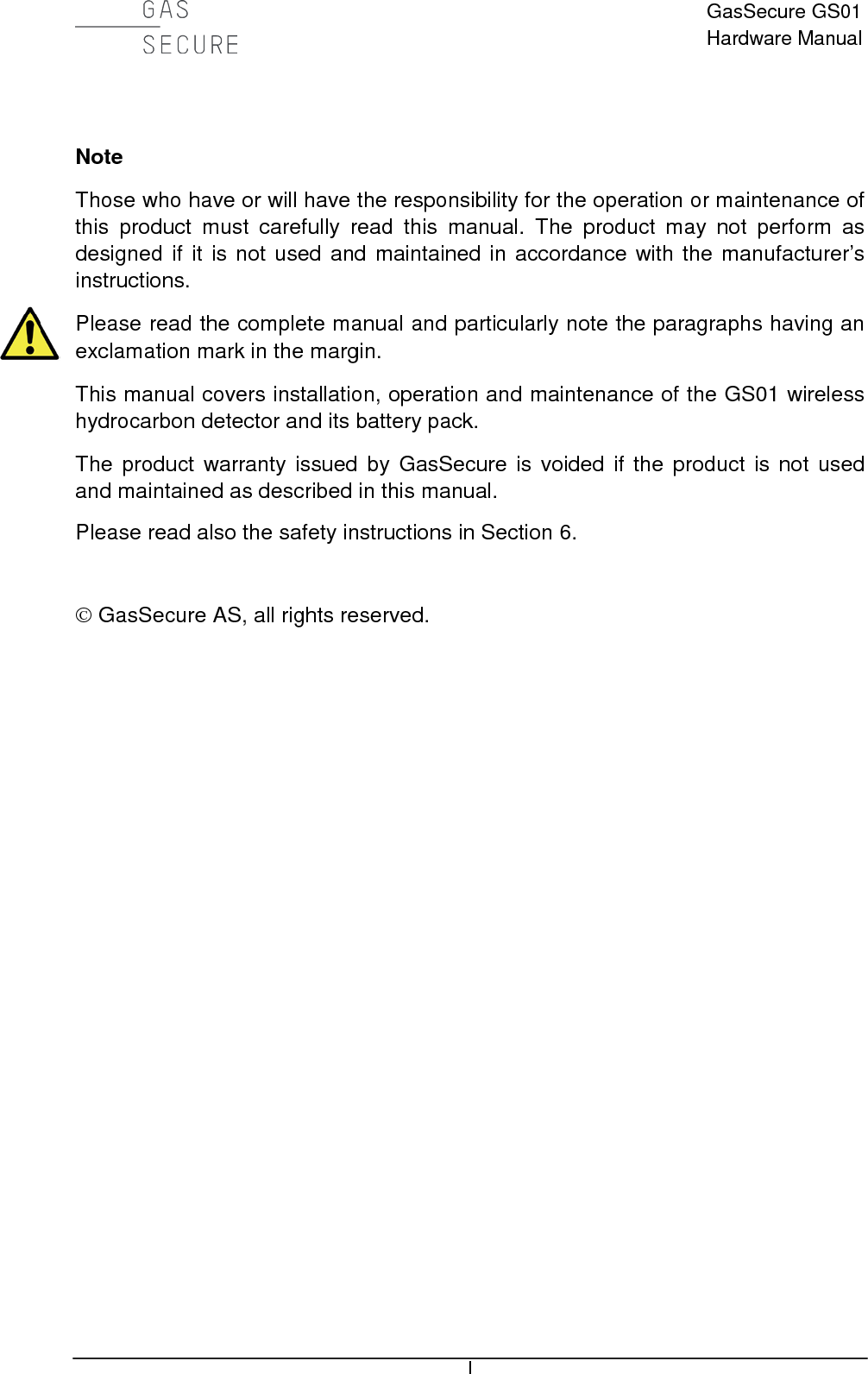
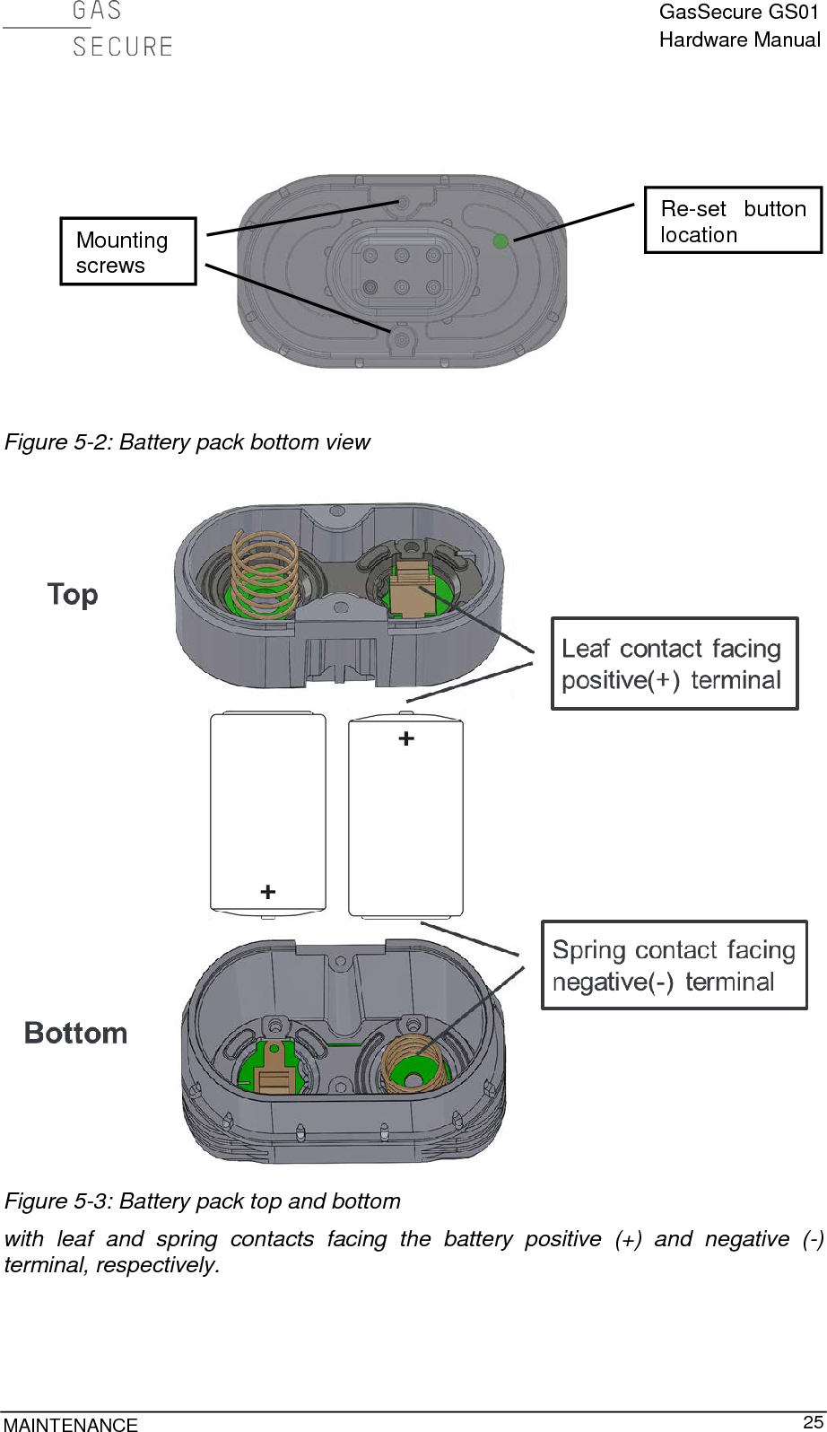
![GasSecure GS01 Hardware Manual DESCRIPTION 7 Figure 1-2: GS01 detector with dimensions in [mm]](https://usermanual.wiki/GasSecure-AS/GS01AA.user-manual/User-Guide-3394610-Page-8.png)
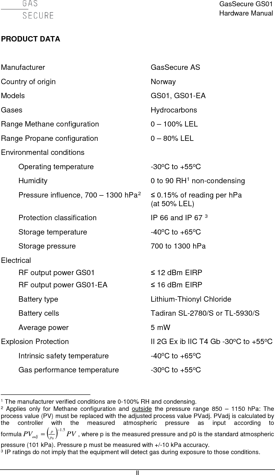
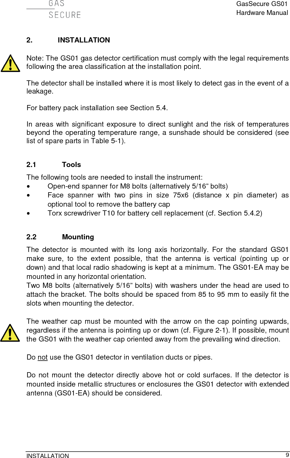
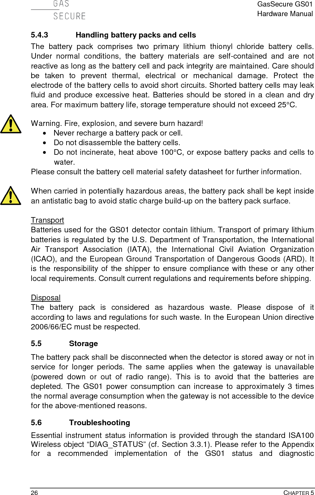
![GasSecure GS01 Hardware Manual 8 CHAPTER 1 Figure 1-3: GS01-EA detector with dimensions in [mm] Figure 1-4: GS01 measuring cell details showing A) External mirror, B) Infrared beam path, C) Sapphire window, D) Ultrasonic sensor with protective sheet](https://usermanual.wiki/GasSecure-AS/GS01AA.user-manual/User-Guide-3394610-Page-9.png)
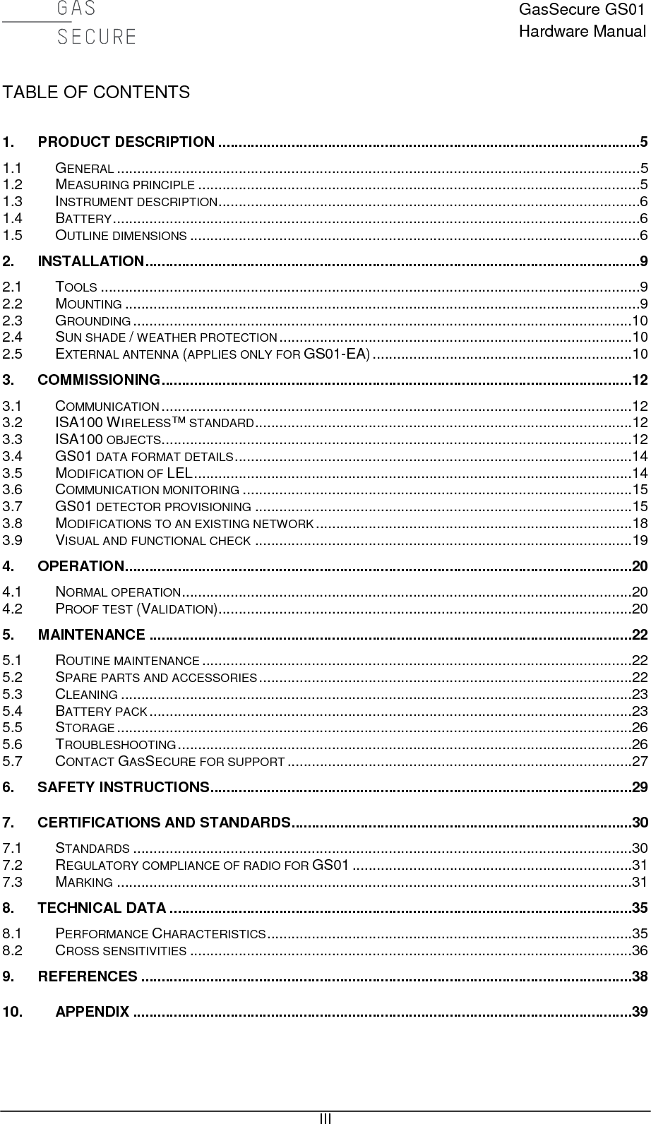
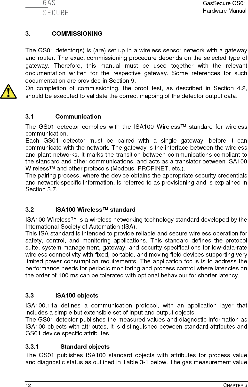
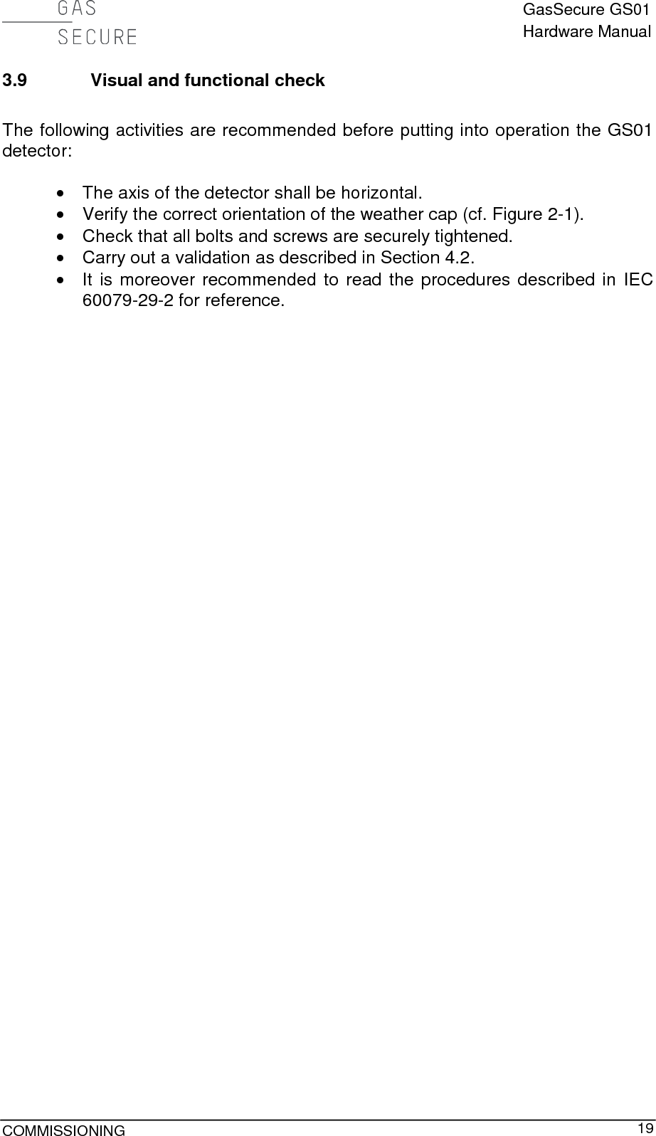
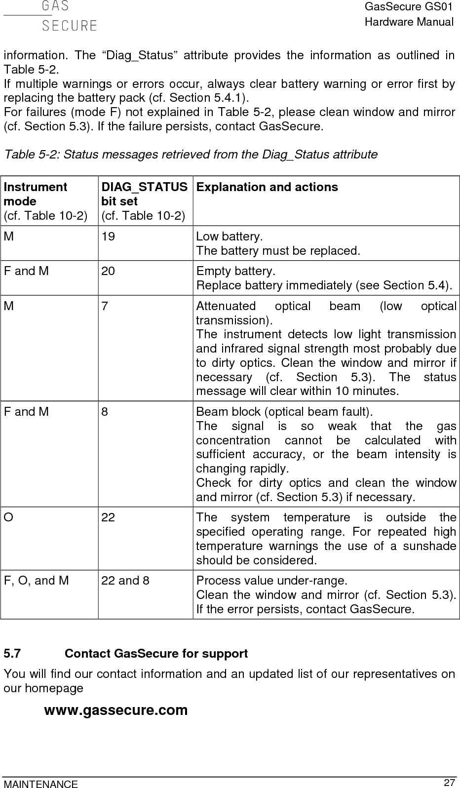
![GasSecure GS01 Hardware Manual 10 CHAPTER 2 2.3 Grounding The detector housing must be connected to ground for operation in hazardous areas. This to avoid possible static charge build-up, which may arise from electrically isolated metal parts. Ground the detector either by mounting it on a grounded metallic structure or by connecting a grounded wire to the screw holes in the mounting bracket (cf. Figure 2-1).The resistance to ground must be less than 1 GOhm. 2.4 Sun shade / weather protection The sunshade is available as optional accessory and recommended for locations with high ambient temperature and / or direct sunlight exposure. It may also be used as weather protection for instance in locations with frequent heavy precipitation. The shade is fixed to the gas detector bracket with the same M8 (or 5/16”) bolts, which are used for detector mounting. Make sure that the sunshade is mounted the correct way so that the detector identification plate remains visible. Figure 2-1: Correct position of the weather cap and location of earth point. The arrow must always point up regardless of the detector orientation. 2.5 External antenna (applies only for GS01-EA) The external antenna is connected to the detector with the antenna cable as shown in Figure 2-2. The properties of the antenna cable supplied by GasSecure are shown in Table 2-1. The GS01-EA detector is certified with the coaxial cable and the omni-directional antenna in Table 5-1. Note that the approved cable length range is 0-30 m. Do not connect any other antennas than those listed in Table 5-1. The external antenna is delivered with a bracket (refer to Reference [10] for bracket dimensions) and metal bands for easy fitting to a pole (25 – 101 mm) or External earth point](https://usermanual.wiki/GasSecure-AS/GS01AA.user-manual/User-Guide-3394610-Page-11.png)
![GasSecure GS01 Hardware Manual INSTALLATION 11 similar. Make sure, to the extent possible, that the antenna is mounted vertical (pointing up or down) and that local radio shadowing is kept at a minimum. Please read also the safety instructions in Section 6. Table 2-1: Properties of standard antenna cable for the GS01-EA Loss/m at 2.5 GHz [dB] Diameter [mm] Bend radius [mm] Weight per m [g] 0.21 10.3 100 115 Figure 2-2: GS01-EA layout with antenna connectionsOmni-directional antenna N-type connector Antenna cable Housing N-type connector](https://usermanual.wiki/GasSecure-AS/GS01AA.user-manual/User-Guide-3394610-Page-12.png)
![GasSecure GS01 Hardware Manual 14 CHAPTER 3 communication. The GS01 uses the PROFIsafe profile over PROFINET as tool for safe communication. In this setup the GS01 acts as F-Slave, a passive communication peer able to perform PROFIsafe. Its counterpart is the F-Host, a data processing unit able to perform PROFIsafe and to trigger the F-Slave for data exchange. The F-Host must be compliant with the PROFIsafe requirements so that end-to-end communication through a black channel, defined by the IEC 61508 standard, can be established. Please refer to the GS01 safety manual [RD 9] for further information on how to set up safe communication with PROFIsafe. For applications without PROFIsafe the “SafeData” object shall be disregarded. 3.4 GS01 data format details The GS01 data objects can be mapped into 16 bit Modbus input registers. The “PV” object (cf. Section 3.3.1) normally populates three registers; the PV_Status byte populates the last 8 bits of the first register and the 32 bit float number populates the following two registers. The “UAPMO.DIAG_STATUS” object (cf. Section 3.3.1) is normally mapped into two 16 bit registers. Some gateways will also add a status byte into the preceding register. This status byte may be ignored, because its information is already contained in the PV_status byte. The procedure for Modbus register mapping depends on the specific gateway, please consult the respective gateway manual on how to achieve this mapping. GasSecure can assist with advice if needed. 3.5 Modification of LEL Regionally different conversion factors may apply for the display of measured concentrations in percent of the lower explosion limit (LEL). The GasSecure GS01 gas detector allows you to select one of two LEL categories, which basically correspond with common explosion limits in the USA (NIOSH Pocket Guide to Chemical Hazards4) and Europe IEC 60079-20), cf. Table 3-2. The factory default setting is LEL according to IEC. The LEL category may be changed with the GS01 Configurator tool as part of device provisioning as explained in Section 3.7. Note that this feature is supported for GS01 firmware version ≥ 3.3. Table 3-2: LEL values in [% vol] according to IEC and NIOSH LEL values [% vol] for IEC (factory default) NIOSH Methane 4.4 5.0 Propane 1.7 2.1 4 See http://www.cdc.gov/niosh/npg/](https://usermanual.wiki/GasSecure-AS/GS01AA.user-manual/User-Guide-3394610-Page-15.png)
![GasSecure GS01 Hardware Manual 16 CHAPTER 3 Software tools, drivers, and files (e.g. CF) are available for download at http://tools.gassecure.com. This procedure can be carried out with an unprovisioned GS01 or with a GS01 that earlier has been provisioned to another gateway. 3.7.1 Yokogawa gateways a) Connect the GS01 to a PC with the GS01 Configurator installed using the GS01 serial adapter. b) Run the GS01 Configurator and select the correct COM port. Keep the default mode “Provision one GS01 device”. Press the “Connect” button and verify that the device information is displayed, cf. Figure 3-1. Press the “Read version info” button if the device information does not show automatically. Press the “Read” button so that the current provisioning status of the device is displayed. c) Enter the device tag and the required network ID in decimal format, cf. Figure 3-1. d) For the join key there are two options. i. Specific (user-defined) join key: Type a 32-bit hexadecimal number in the “join key” field. ii. Generate a random join key: Press the “Generate random join key” button. e) Check and set the LEL category to either IEC or NIOSH as defined in Table 3-2. f) Check the destination folder for the ypif file and change it by pressing the “...” button if necessary. Press the “Generate ypif file” button. This file must be uploaded to the gateway (explained in reference [RD 4]) to enable communication. Press the “Apply” button (do not make any changes to the provisioning input data between pressing the two buttons!). g) Close and exit the GS01 Configurator and disconnect the GS01 detector from the PC. h) Power up the GS01 by inserting the battery pack. i) The GS01 device should join the network within 5-20 minutes, if it is within radio distance to the gateway and the gateway is set up properly (refer to reference [RD 4]). If the gateway is out of radio range, the GS01 device will try to connect for a period of 60 min and then enter a power-saving mode. In this mode it will try to connect for a 5 min period once per hour.](https://usermanual.wiki/GasSecure-AS/GS01AA.user-manual/User-Guide-3394610-Page-17.png)
![GasSecure GS01 Hardware Manual 18 CHAPTER 3 h) Power up the GS01 by inserting the battery pack. i) The GS01 device should join the network within 5-20 minutes, if it is within radio distance to the gateway and the gateway is set up properly. If the gateway is out of radio range, the GS01 device will try to connect for a period of 60 min and then enter a power-saving mode. In this mode it will try to connect for a 5 min period once per hour. 3.7.3 Over the air (OTA) provisioning a) Connect the GS01 to a PC with the GS01 Configurator installed using the GS01 serial adapter. b) Run the GS01 Configurator and select the correct COM port. Keep the default mode “Provision one GS01 device”. Press the “Connect” button and verify that the device information is displayed, cf. Figure 3-1. Press the “Read version info” button if the device information does not show automatically. Press the “Read” button so that the current provisioning status of the device is displayed. c) Press the “Reset radio to factory defaults” button. d) Close and exit the GS01 Configurator and disconnect the GS01 detector from the PC. e) Power up the GS01 by inserting the battery pack. f) The GS01 can now be provisioned over the air (OTA) using either special field tools or the field wireless access points. Refer to references [RD3], [RD6] or [RD 8] for possible solutions from different vendors. 3.8 Modifications to an existing network 1. Add a detector Provision the GS01 as described in Section 3.7. Mount the GS01 with battery. Re-configure the gateway to accommodate the additional detector(s) (cf. Section 9 for gateway relevant documentation). 2. Replace a detector Power down the GS01 in question by removing its battery. Provision the replacement GS01 by following all steps in Section 3.7. Mount the replacement GS01 with battery. Re-configure the gateway to accommodate the replacement detector(s) (cf. Section 9 for gateway relevant documentation). 3. Remove a detector Power down the GS01 in question by removing its battery pack. Optional: Re-configure the gateway in order to remove the detector from the list of publishers (cf. Section 9 for gateway relevant documentation).](https://usermanual.wiki/GasSecure-AS/GS01AA.user-manual/User-Guide-3394610-Page-19.png)

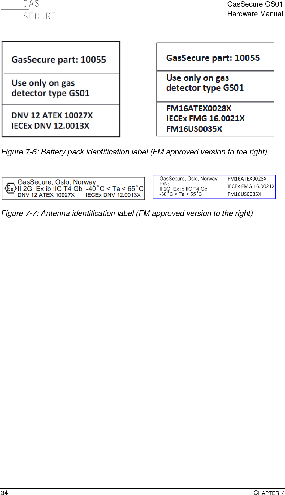
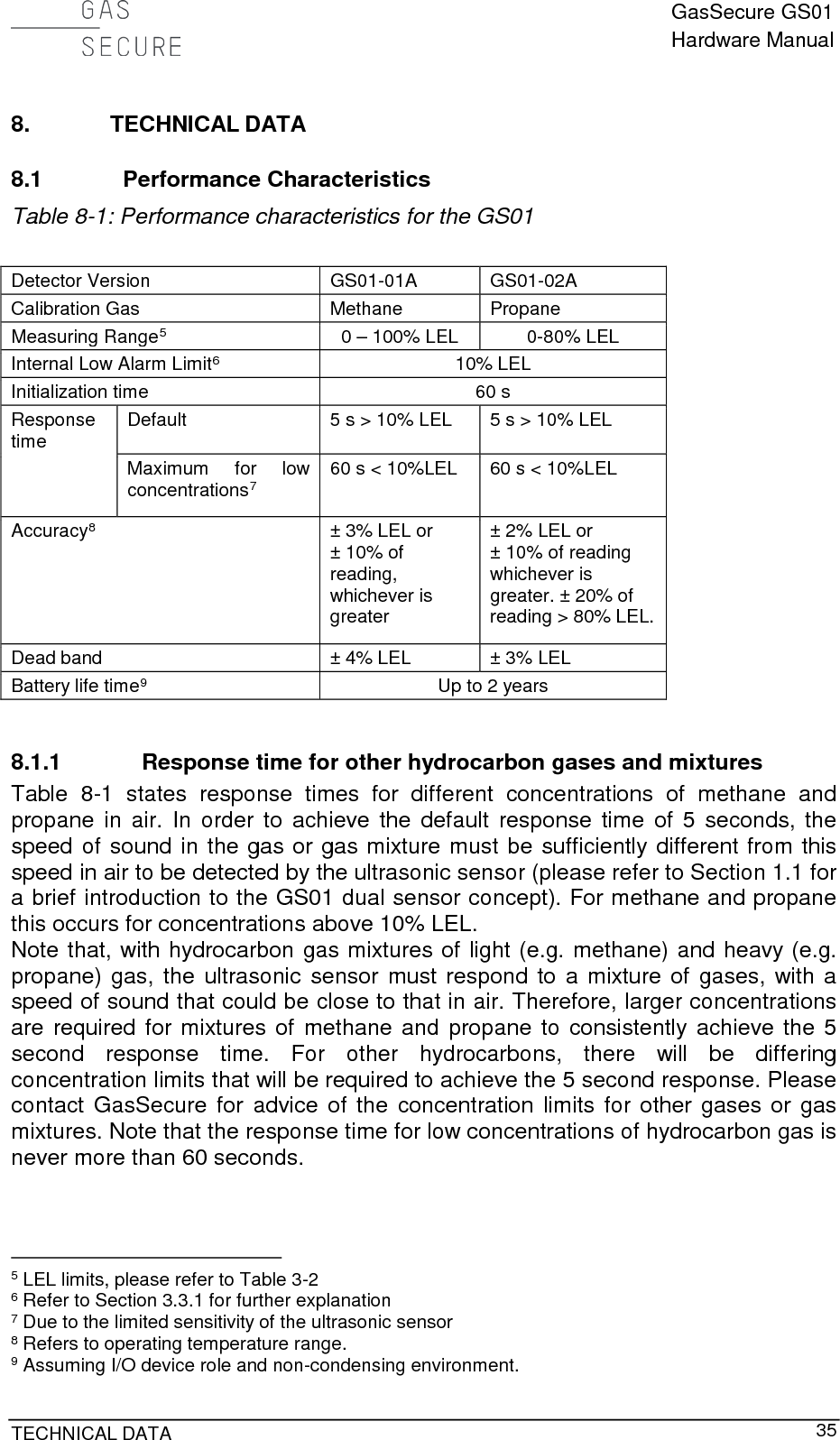
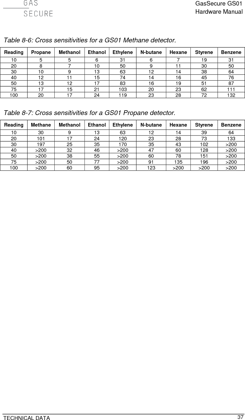
![GasSecure GS01 Hardware Manual 36 CHAPTER 8 8.2 Cross sensitivities The GS01 is sensitive to many hydrocarbon gases, and does not distinguish one from another. In the tables below cross sensitivities to important hydrocarbon gases are presented. Please note that these are modelled estimates and shall be used as an indication only. Please contact GasSecure for cross sensitivity estimates for other gases than those listed below. The tables are read as follows: The instrument reading is looked up in the first column. The estimated actual concentration is found in the same row in the column for the gas to be measured. Example from Table 8-3: If a methane detector is exposed to ethanol and a value of 40 %LEL is read, the actual concentration of ethanol is approximately 15 %LEL. 8.2.1 GS01 detector with LEL according to IEC All values are in % LEL. LEL values as provided in Table 8-2. Table 8-2: LEL values in [% vol] according to IEC60079-20. Methane Propane Methanol Ethanol Ethylene N-butane Hexane Styrene Benzene 4.4 1.7 6.0 3.1 2.3 1.4 1.0 1.0 1.2 Table 8-3: Cross sensitivities for a GS01 Methane detector. Reading Propane Methanol Ethanol Ethylene N-butane Hexane Styrene Benzene 10 5 4 6 34 6 7 16 28 20 9 7 10 54 10 11 25 46 30 11 8 12 69 12 14 32 59 40 14 10 15 81 15 17 38 71 50 15 11 17 91 17 19 43 81 75 19 14 21 113 21 24 53 103 100 23 16 24 131 25 28 61 122 Table 8-4: Cross sensitivities for a GS01 Propane detector. Reading Methane Methanol Ethanol Ethylene N-butane Hexane Styrene Benzene 10 24 7 11 61 11 12 28 52 20 79 14 21 116 22 25 54 106 30 159 21 31 167 33 38 77 164 40 200 27 40 >200 44 52 98 >200 50 >200 32 49 >200 55 67 117 >200 75 >200 43 69 >200 83 111 155 >200 100 >200 52 86 >200 113 167 184 >200 8.2.2 GS01 detector with LEL according to NIOSH All values are in % LEL. LEL values as provided in Table 8-5. Table 8-5: LEL values in [% vol] according to NIOSH. Methane Propane Methanol Ethanol Ethylene N-butane Hexane Styrene Benzene 5.0 2.1 6.0 3.3 2.7 1.6 1.1 0.9 1.2](https://usermanual.wiki/GasSecure-AS/GS01AA.user-manual/User-Guide-3394610-Page-37.png)
![GasSecure GS01 Hardware Manual 38 CHAPTER 9 9. REFERENCES [RD 1] Nivis ISA100.11a R2.7 Monitoring Control System User Guide Version: 1.2, Date: March 30, 2012 [RD 2] Nivis VersaRouter 900 Hardware User Guide (VR800 Internal Hardware Rev. C) Version 1.4, Date: Mar. 18, 2010 [RD 3] Yokogawa YFGW410 Field Wireless Management Station user’s manual, IM 01W02D01-01EN [RD 4] Yokogawa YFGW410 Field Wireless Management Station Startup Guide, TI 01W01A56-01EN [RD 5] Yokogawa YFGW510 Field Wireless Access Point user’s manual, IM 01W02E01-01EN [RD 6] Honeywell Wireless Device Manager User's Guide, Release 220, OWDOC-X254-en-220A, October 2013 [RD 7] Honeywell Field Device Access Point User's Guide, Release 220, OWDOC-X256-en-220A, October 2013 [RD 8] Nivis ISA100.11a Field Tool User Manual, Version 2.1, Date: October 17, 2013 [RD 9] GasSecure GS01 wireless infrared hydrocarbon gas detector, Safety Manual, document ID 21440 [RD 10] HUBER+SUHNER data sheet for Sencity OMNI-M Antenna: 1324.170114](https://usermanual.wiki/GasSecure-AS/GS01AA.user-manual/User-Guide-3394610-Page-39.png)