GemTek Technology WLTFQR121GN LTE router User Manual
Gemtek Technology Co., Ltd. LTE router
UserManual.wiki
>
GemTek Technology
>
WLTFQR121GN User Manual
>
User manual
Contents
1.
User manual (statement)
2.
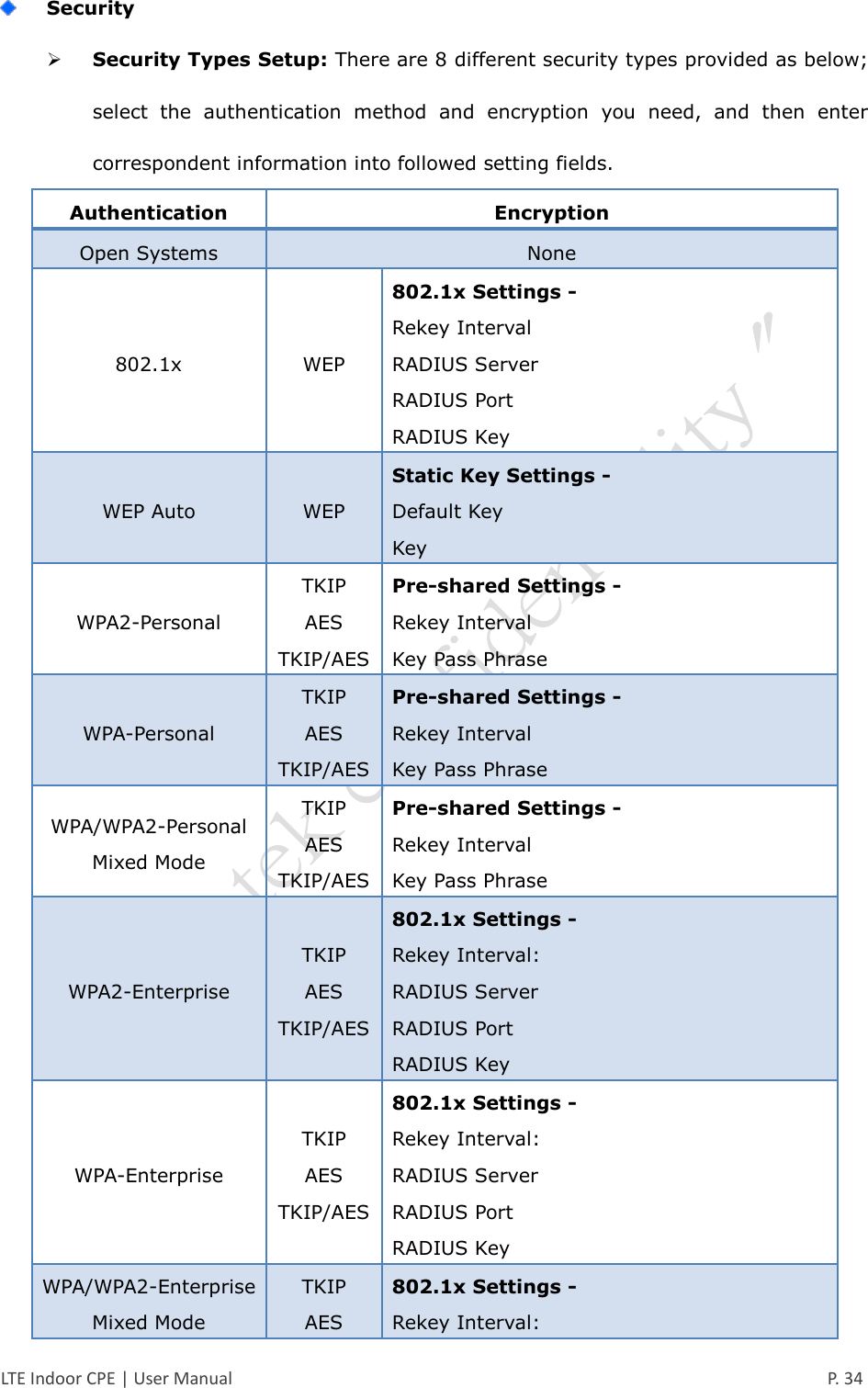
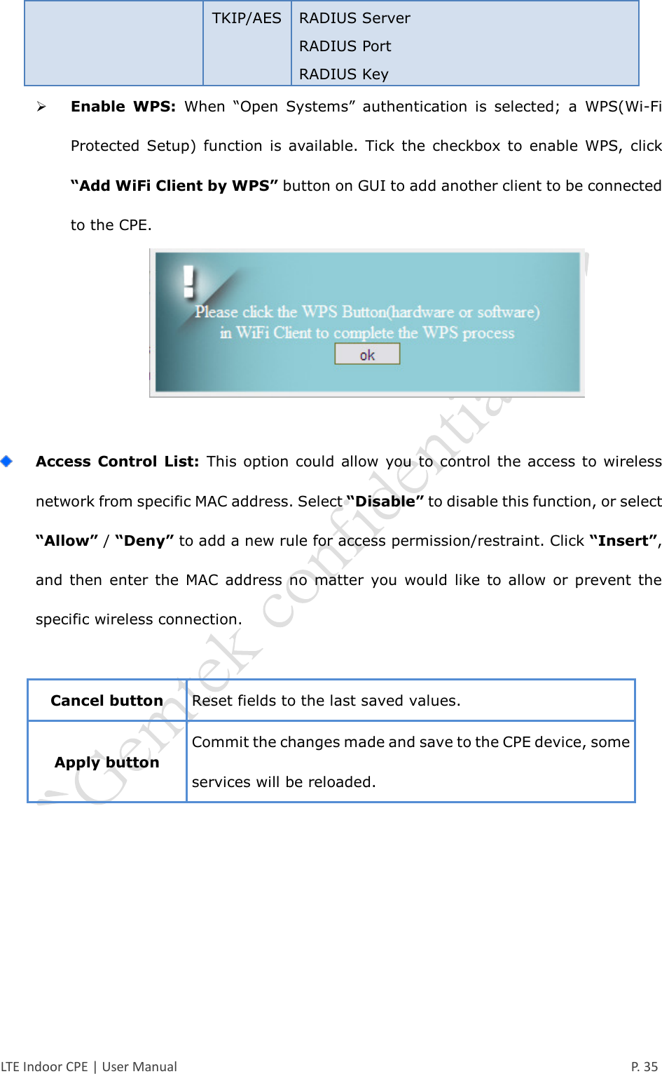
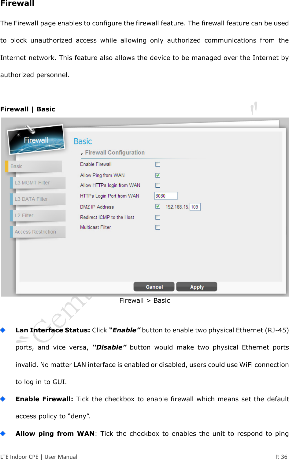
User manual
User manual
Navigation menu
Upload a User Manual
Namespaces
Wiki Guide
HTML
PDF
Info
Views
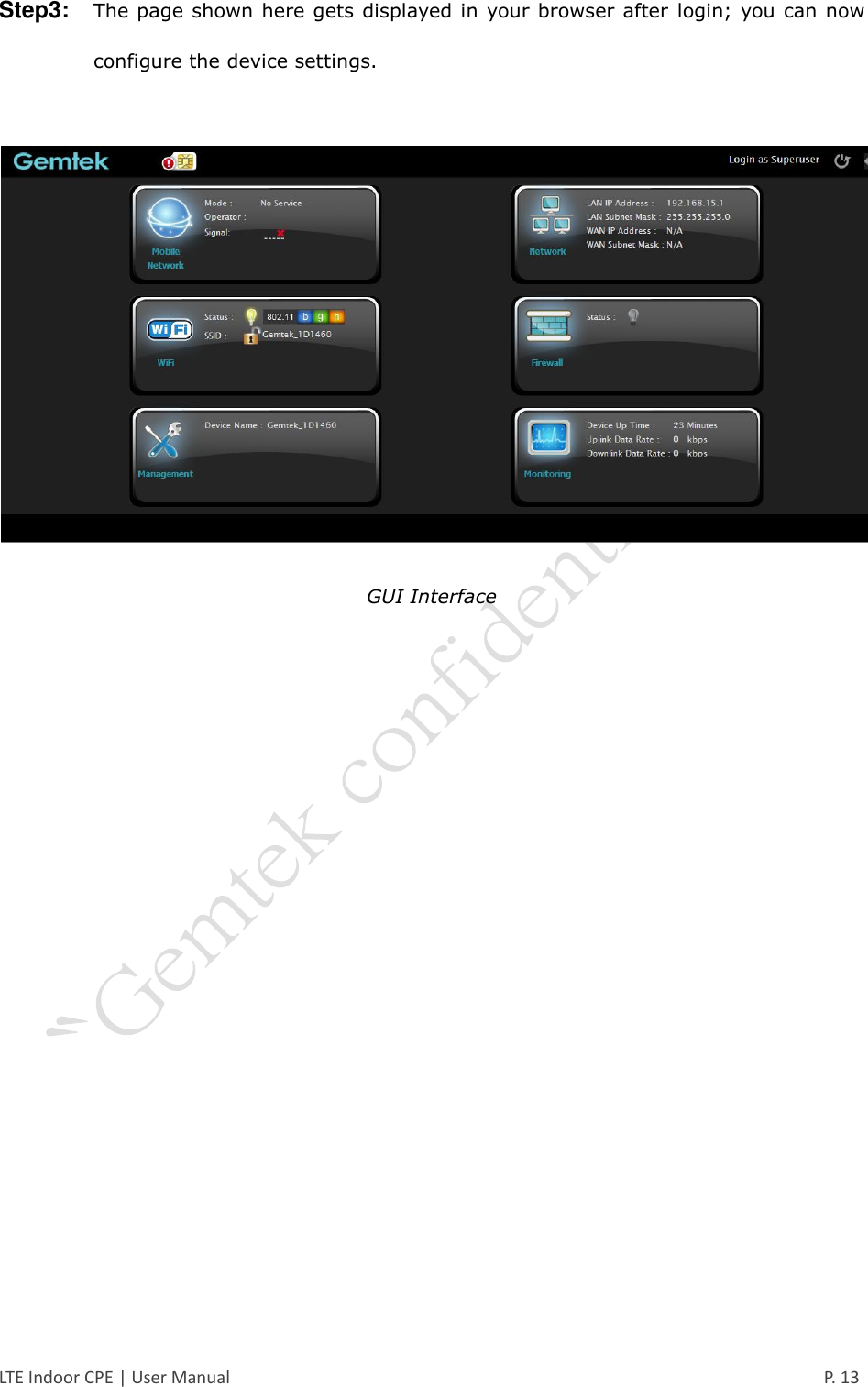
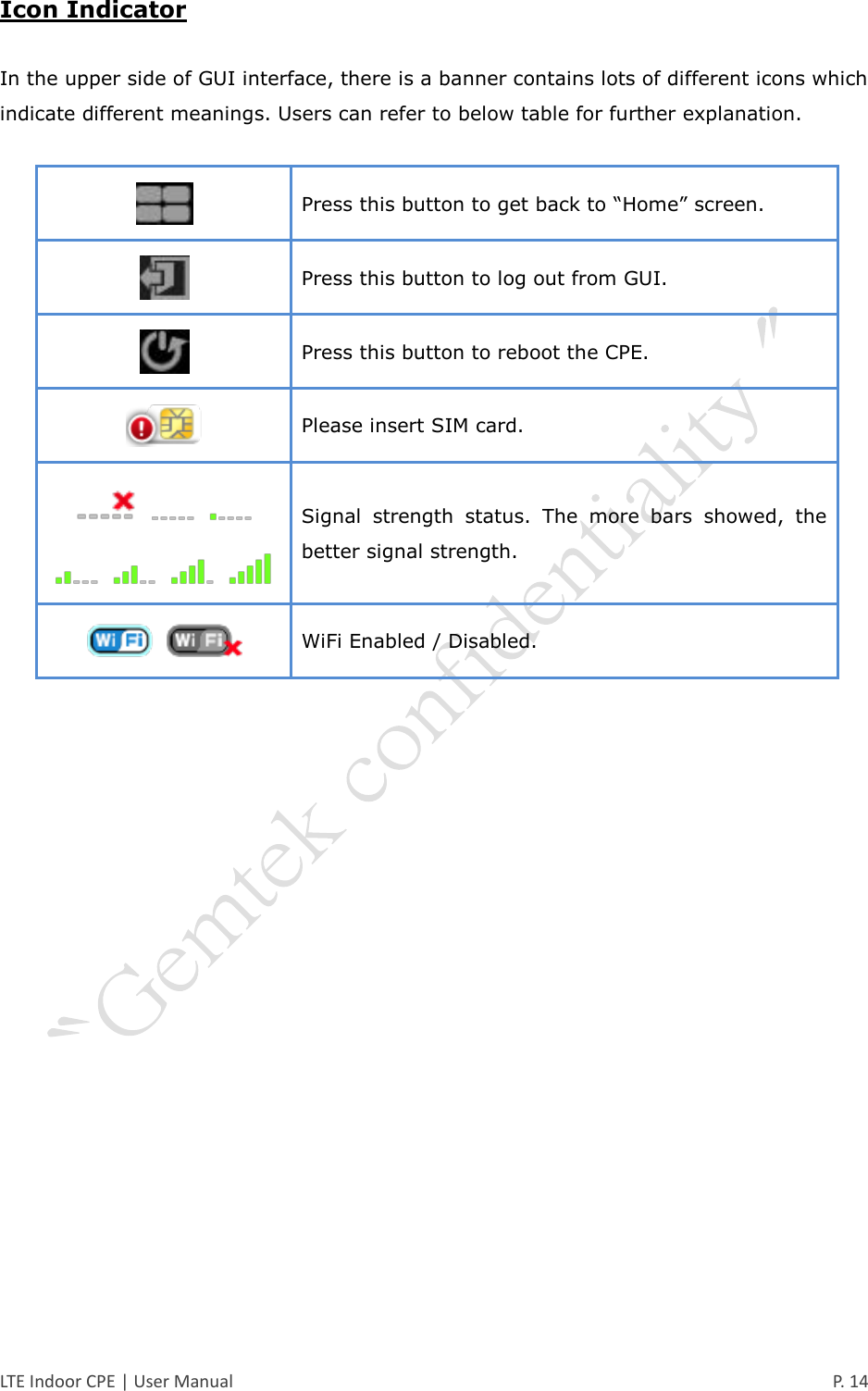
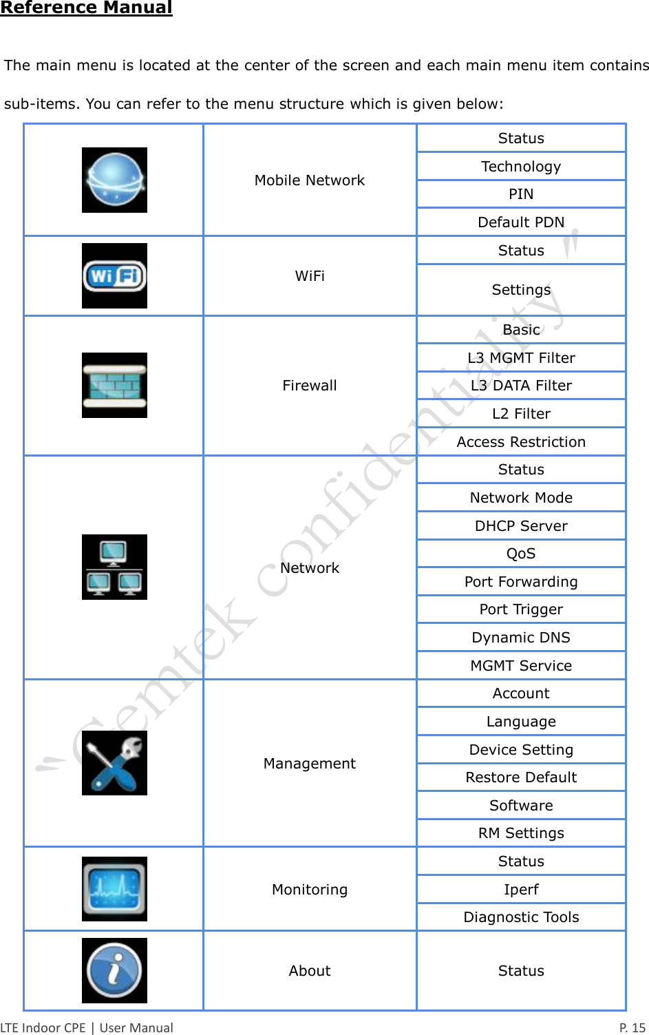
User Manual
Discussion / Help
Navigation