Gilbarco LFSQR TRIND M01560 Module User Manual 13 0072 Exhibit Cover
Gilbarco Inc. TRIND M01560 Module 13 0072 Exhibit Cover
UserManual.wiki
>
Gilbarco
>
LFSQR User Manual
Manual
Navigation menu
Upload a User Manual
Namespaces
Wiki Guide
HTML
PDF
Info
Views
User Manual
Discussion / Help
Navigation
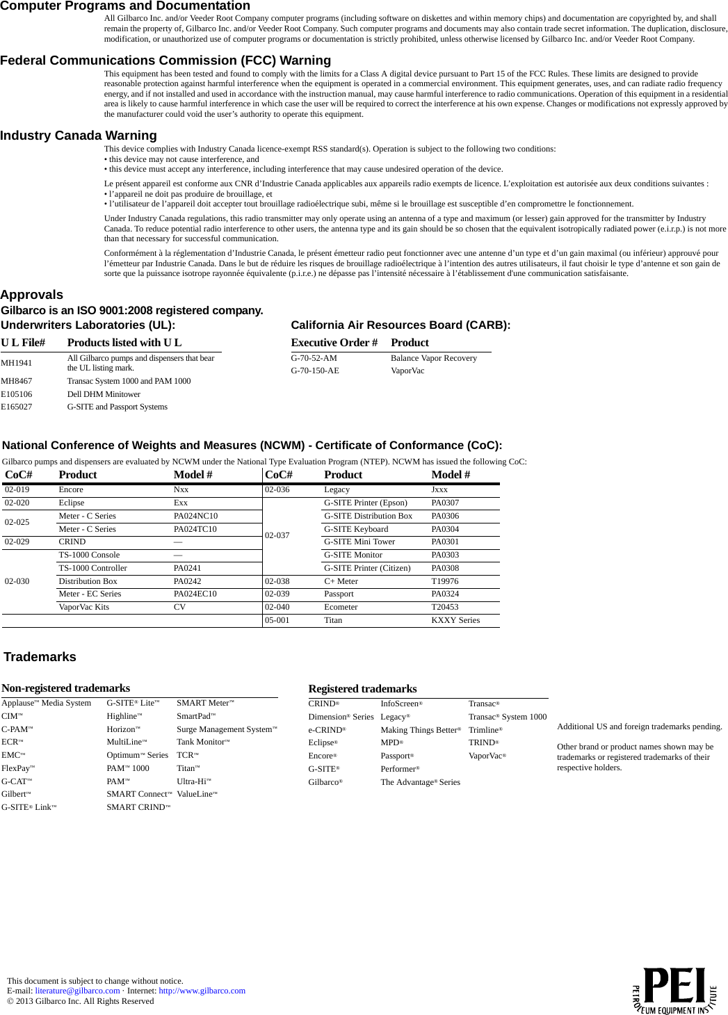
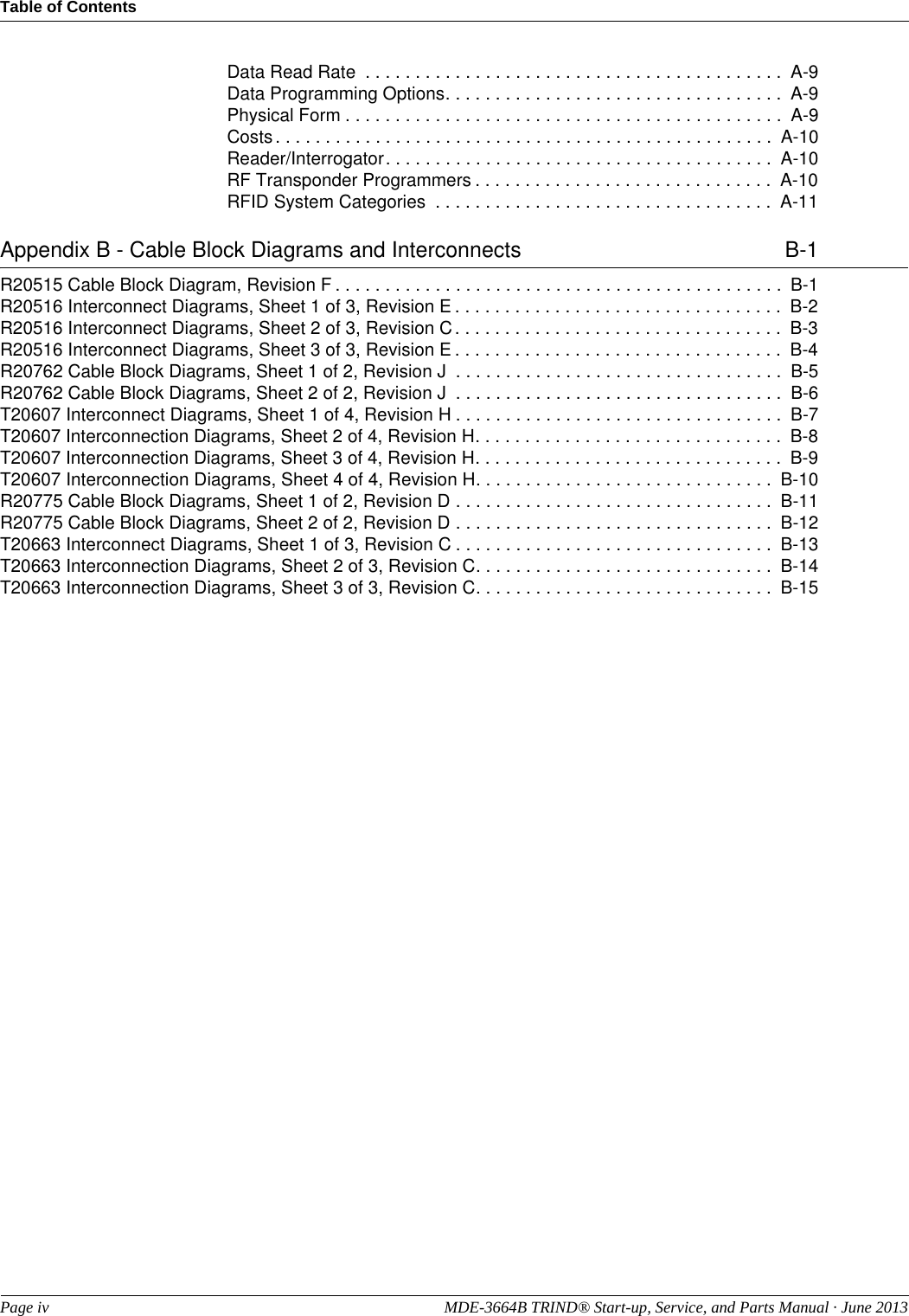
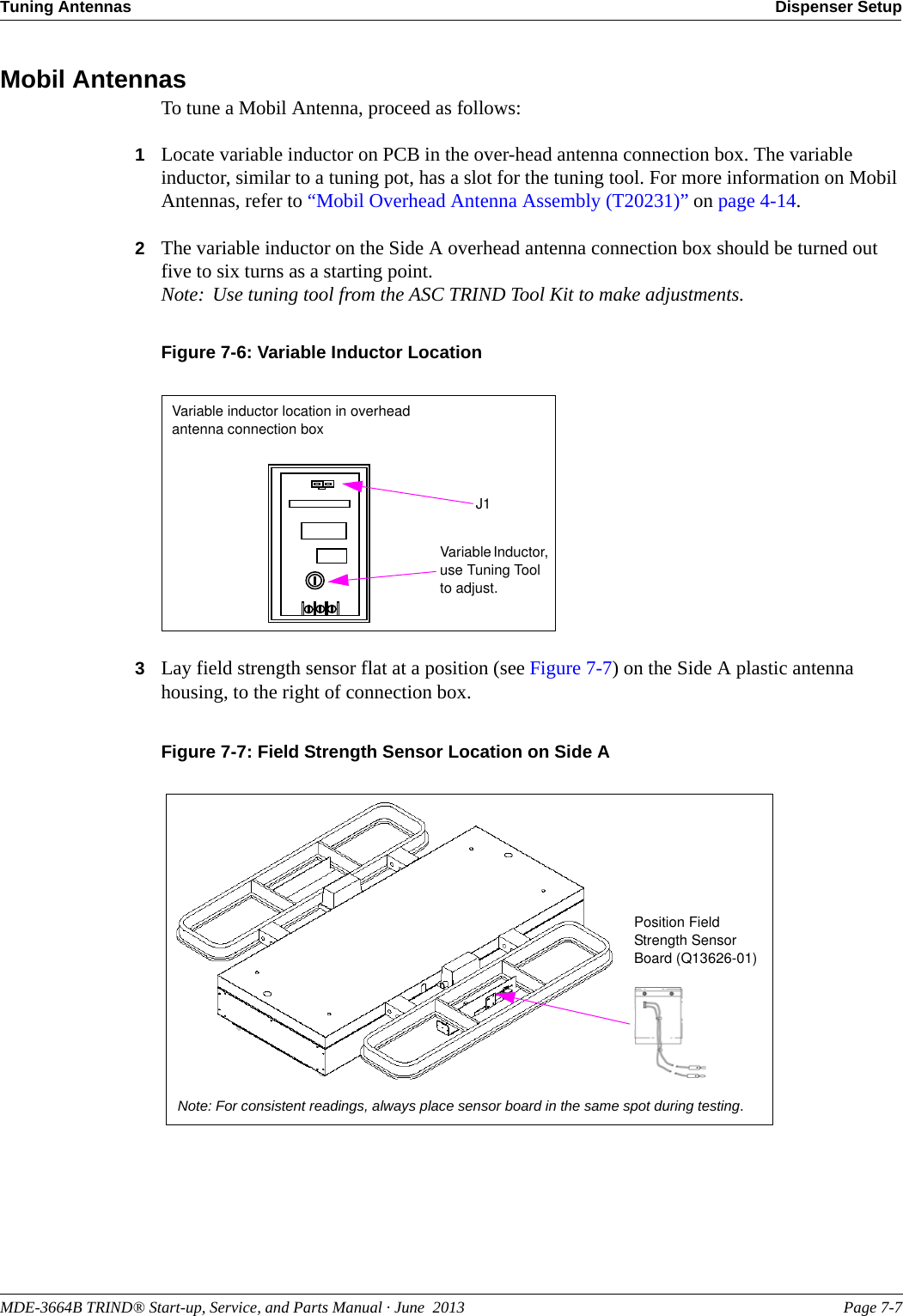
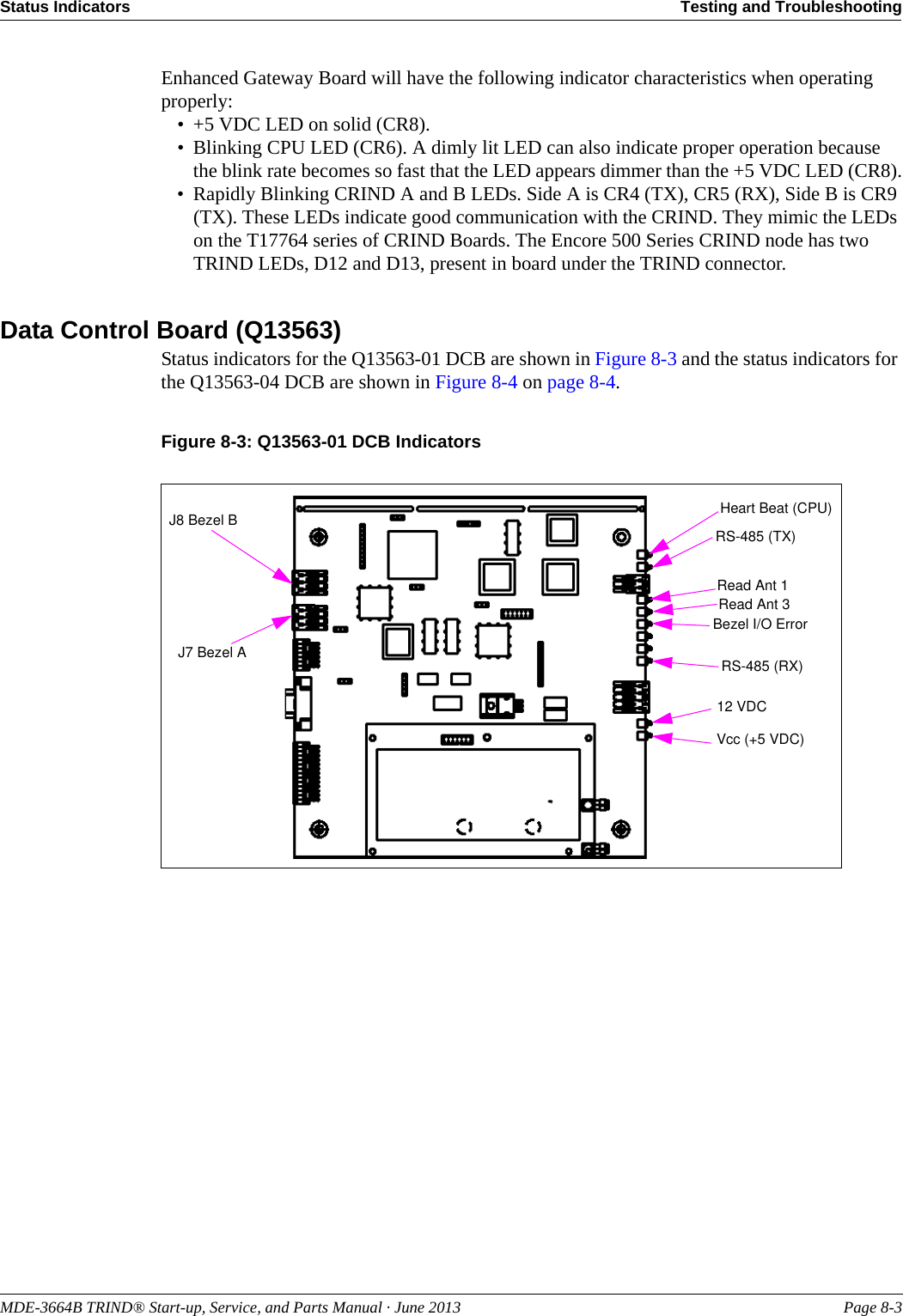
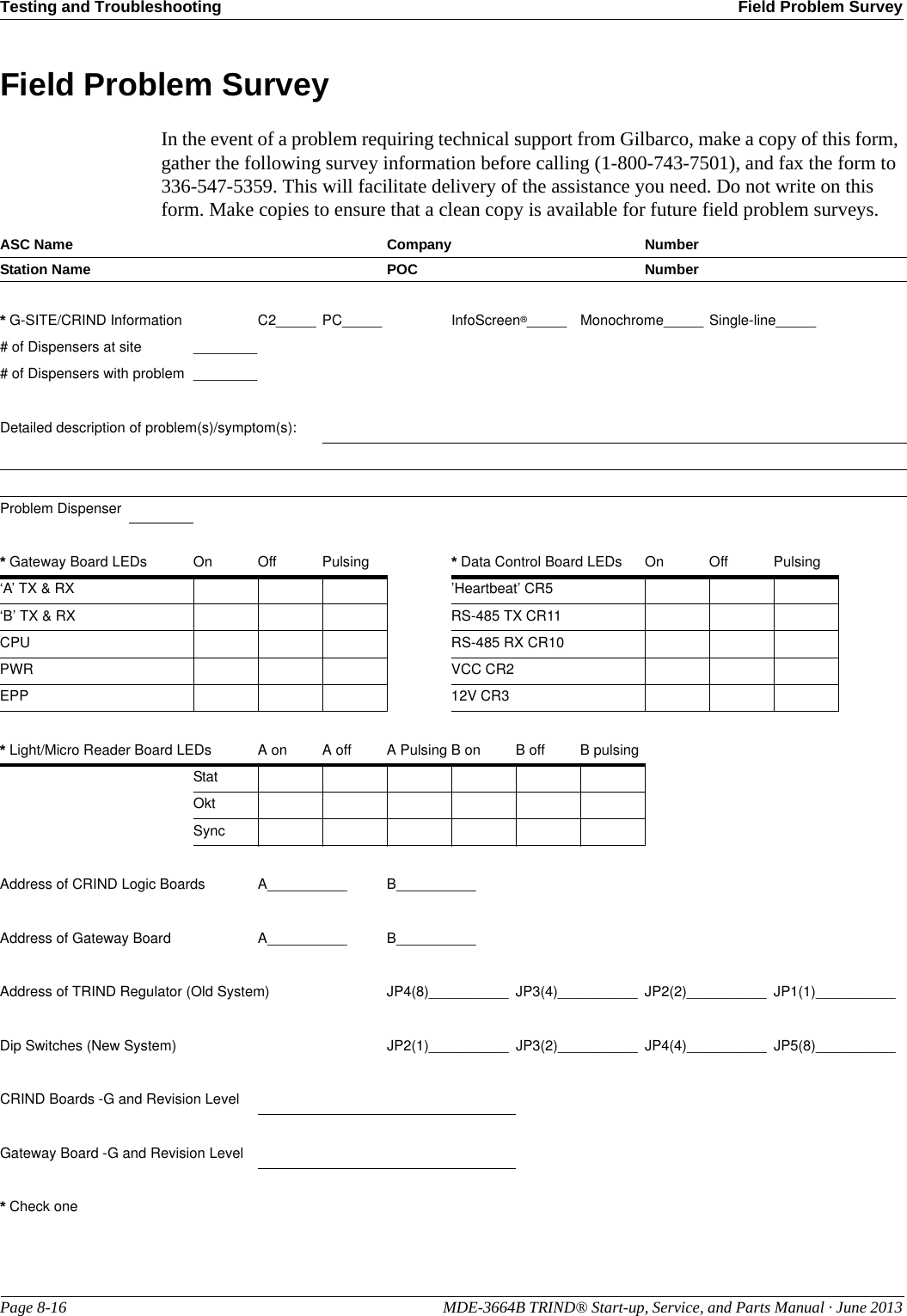
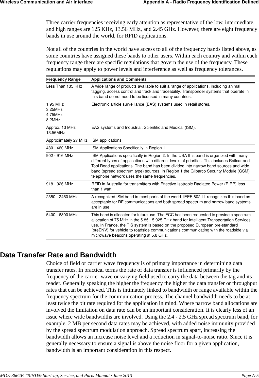
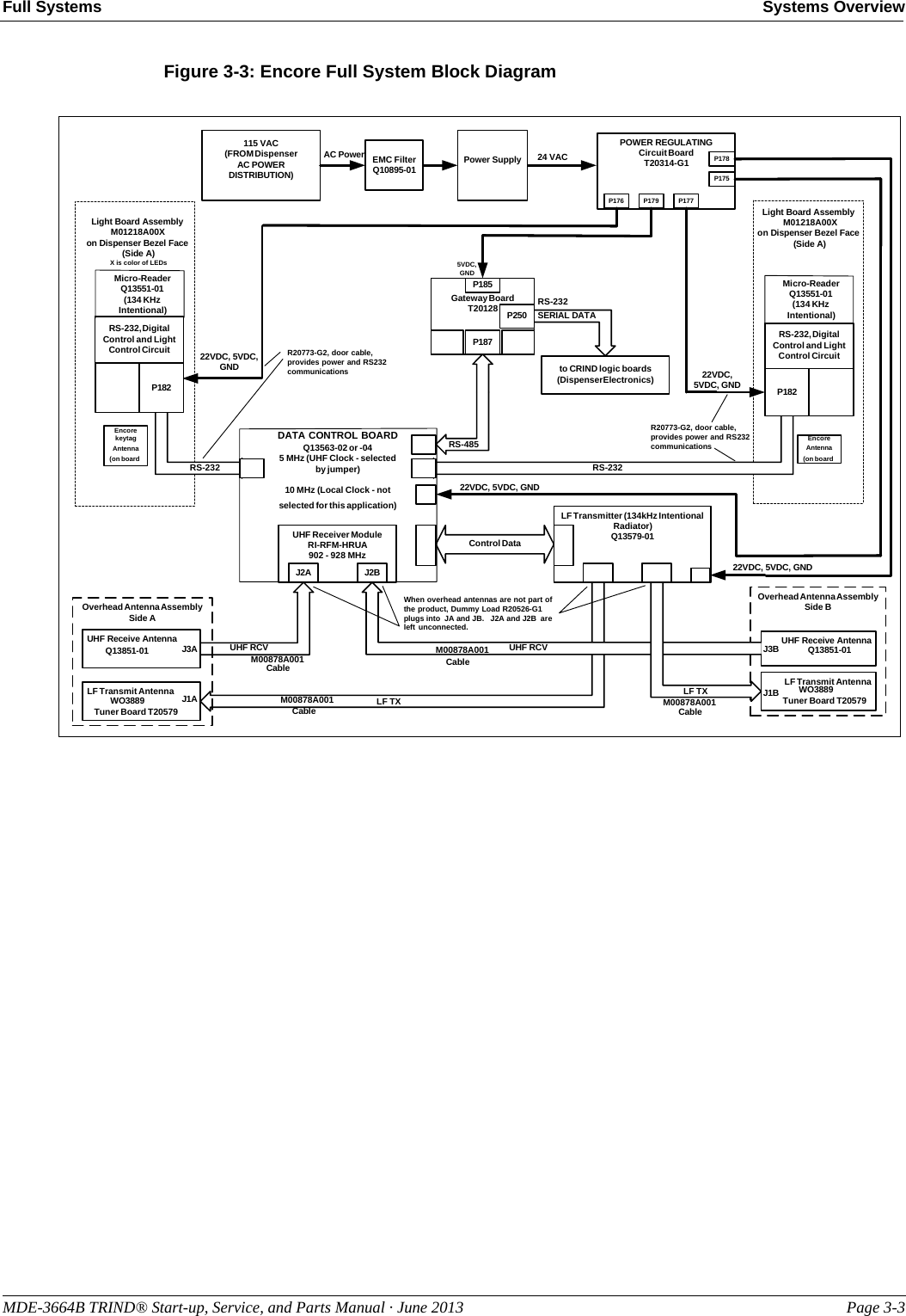
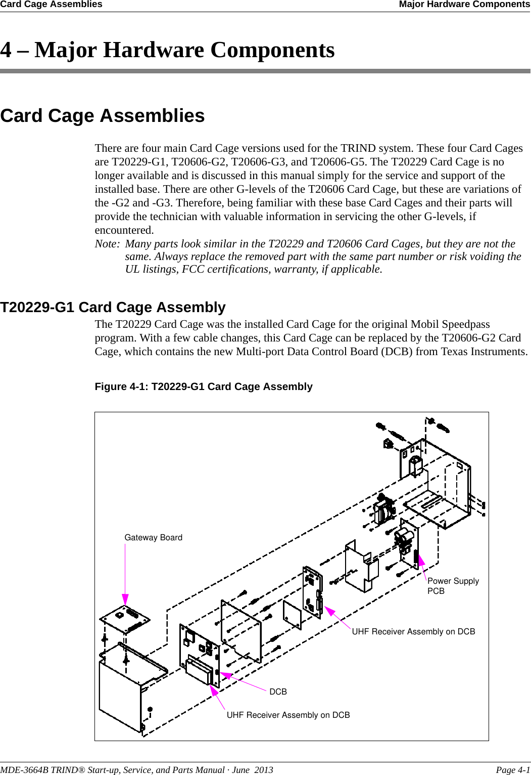
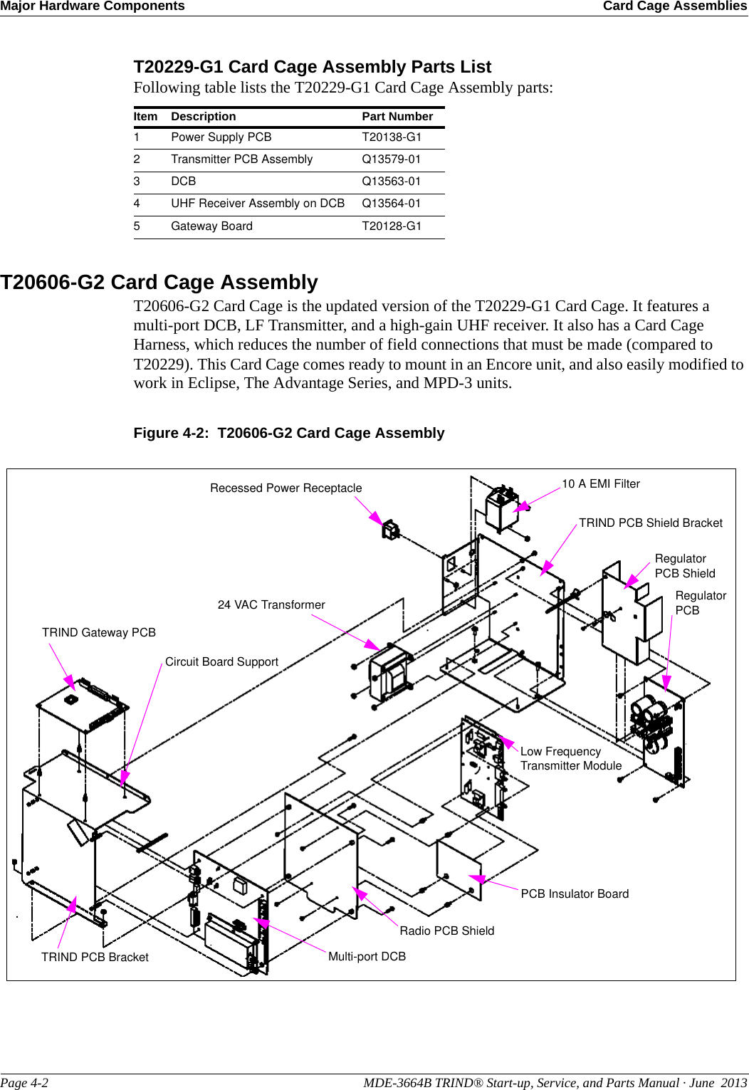
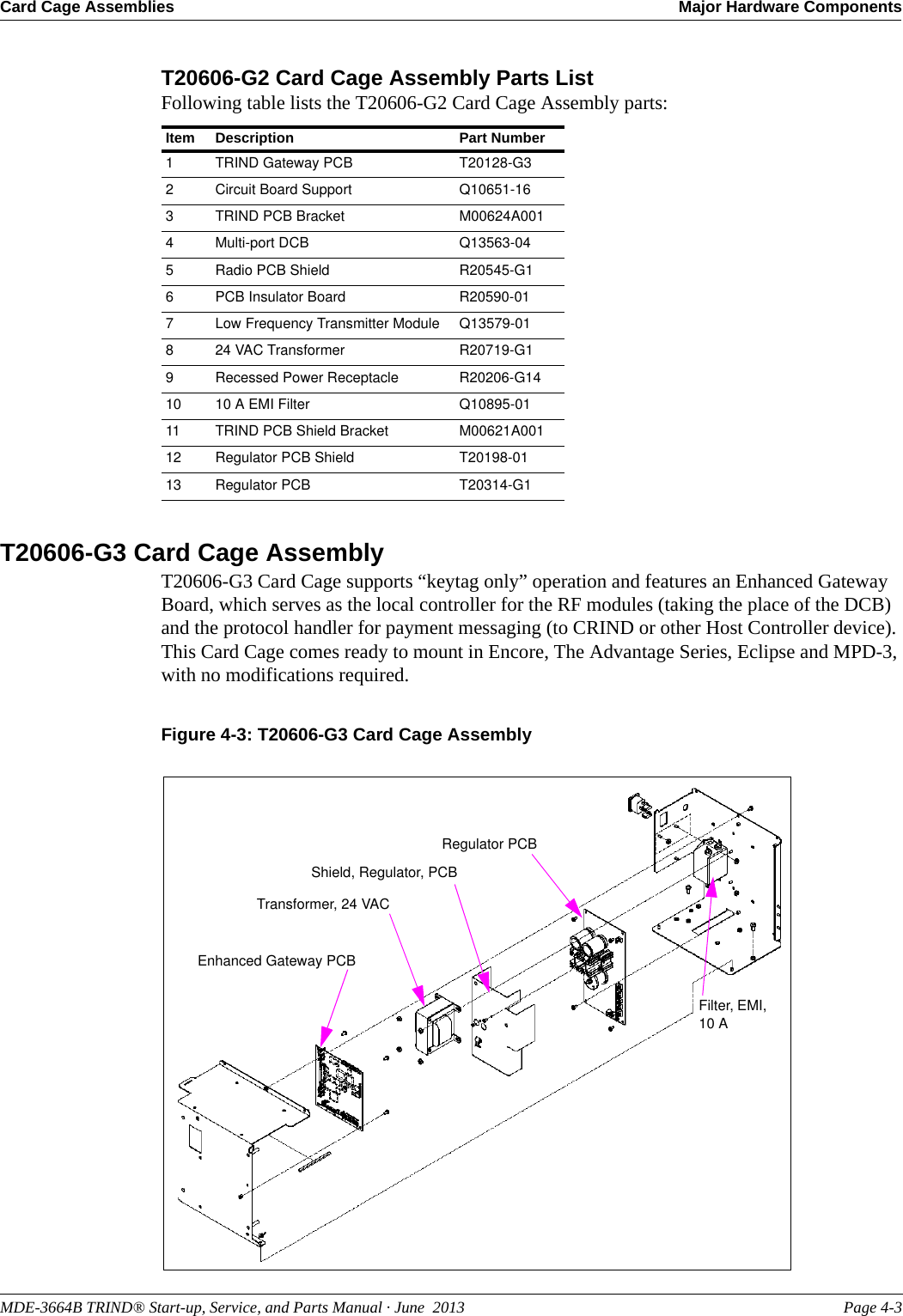
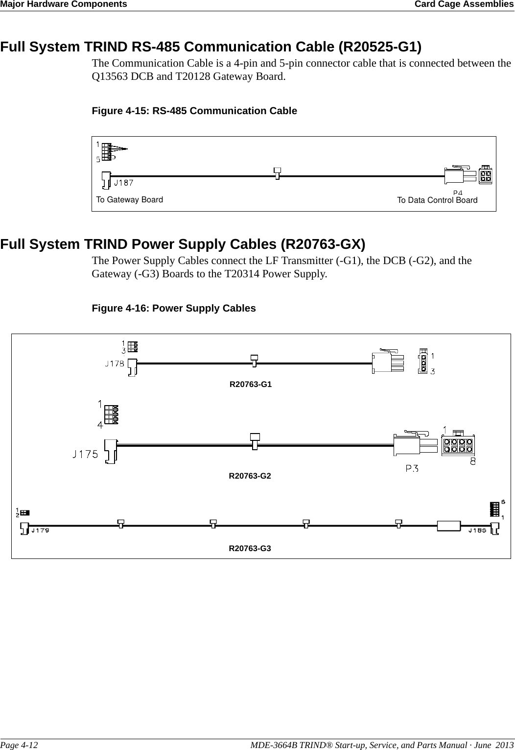
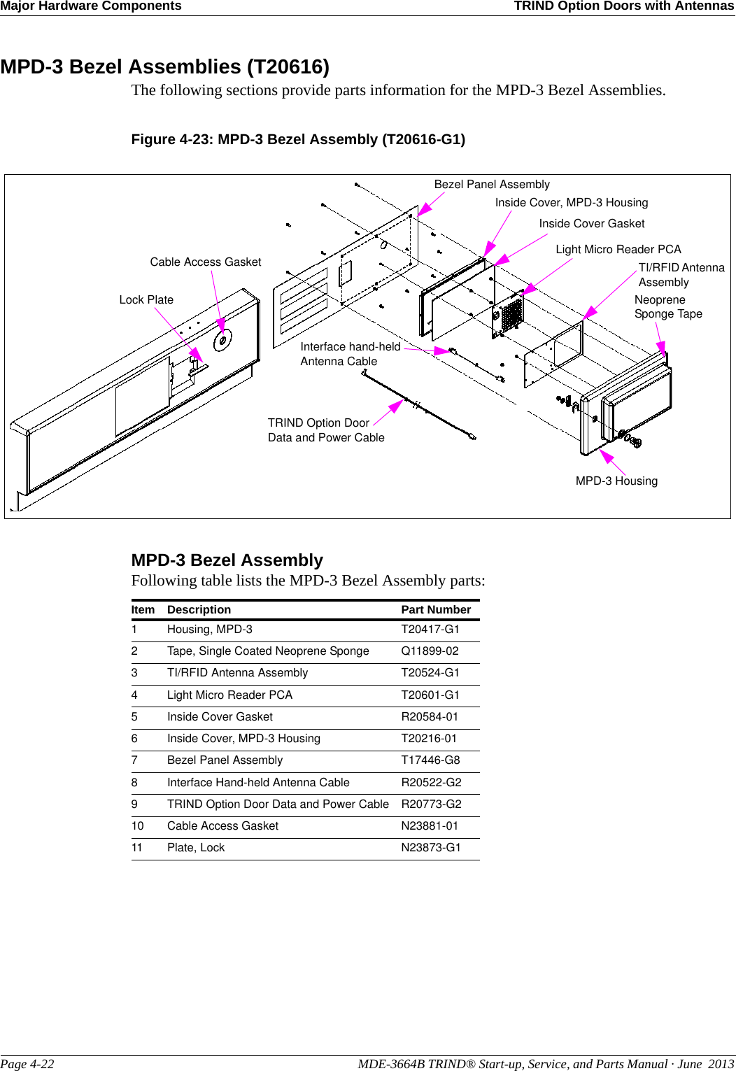
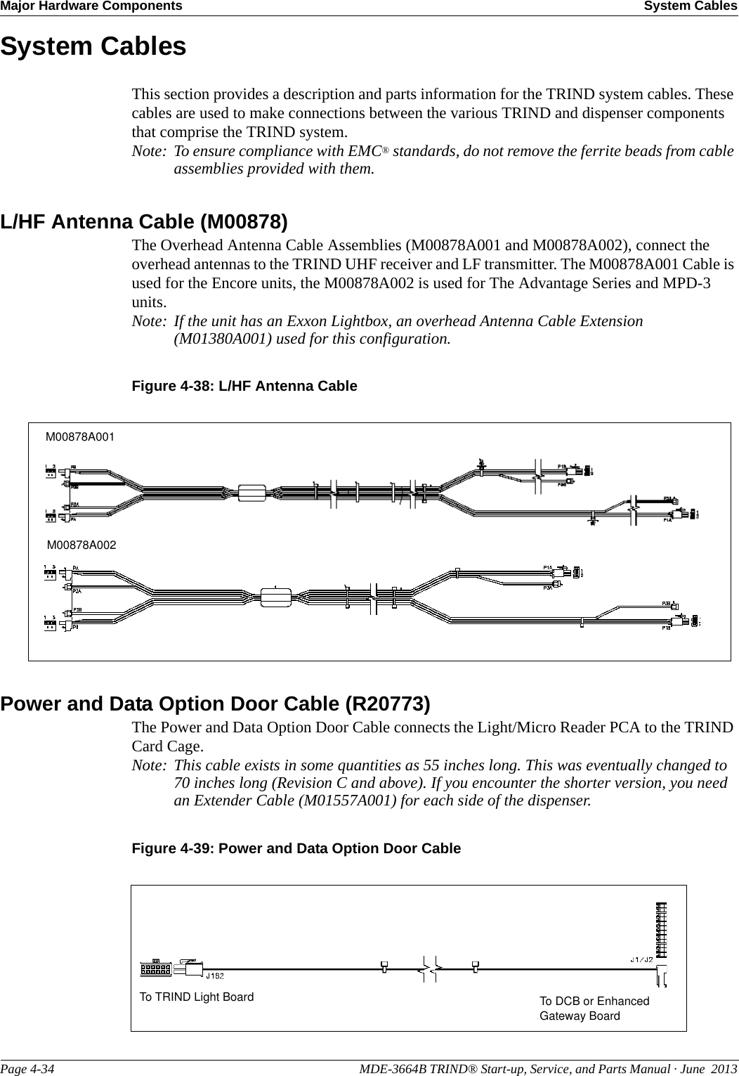
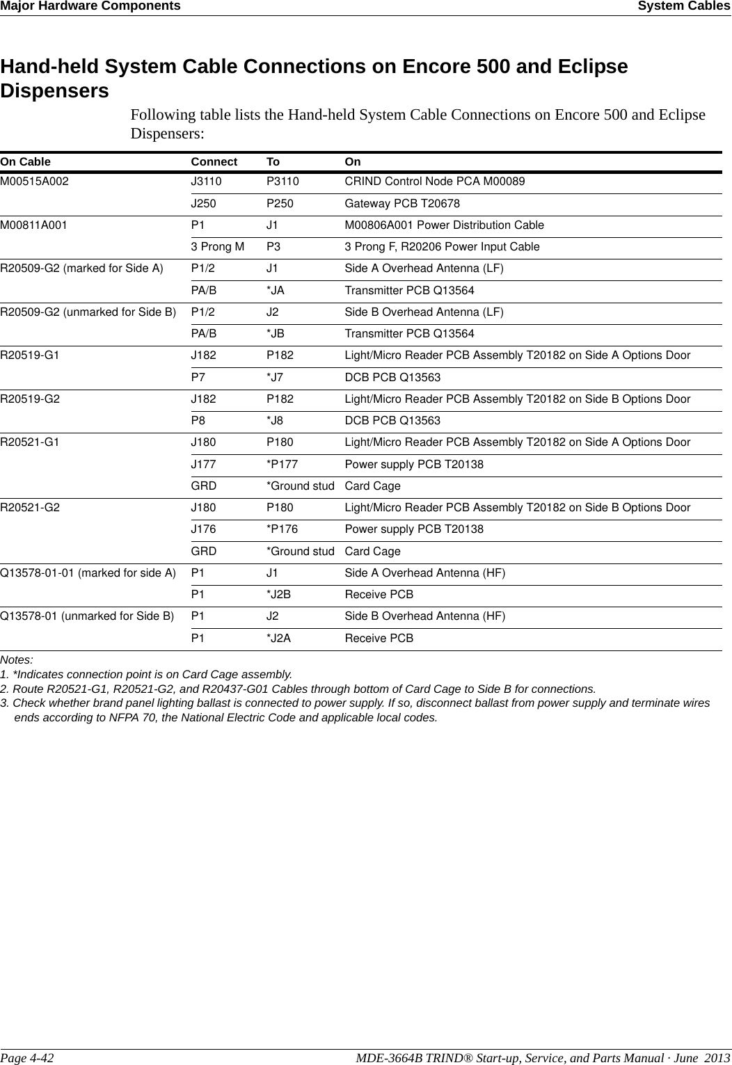
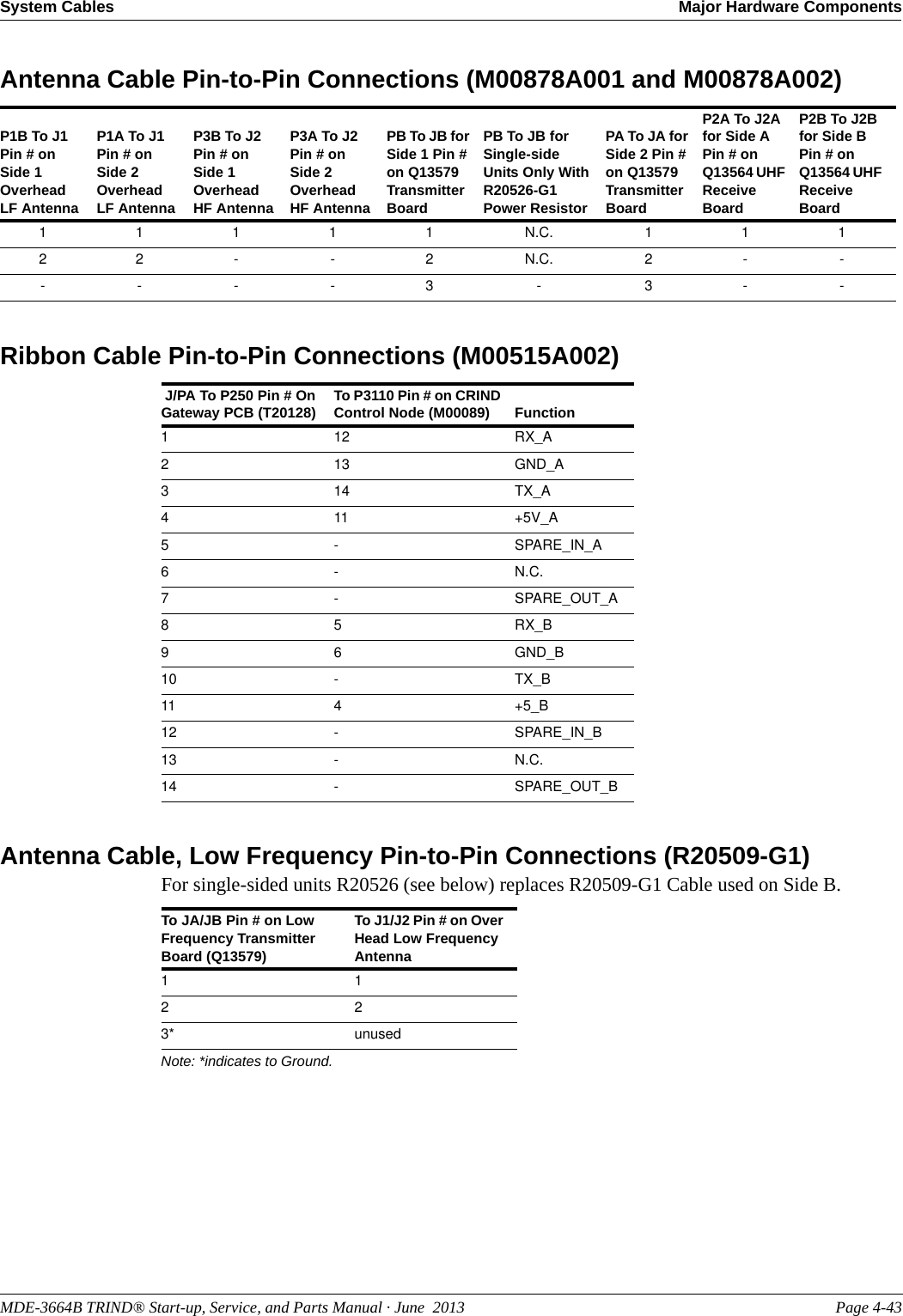
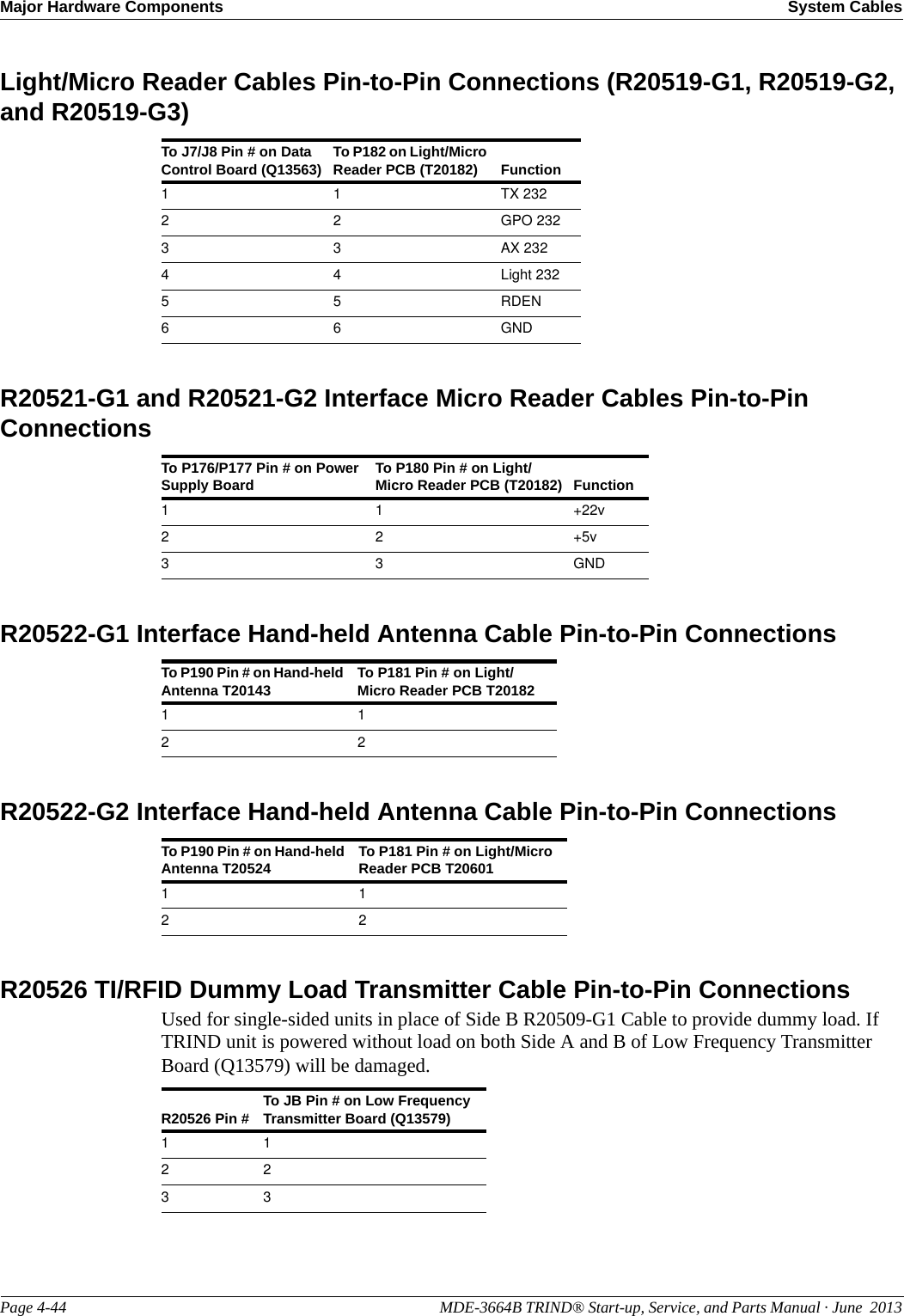
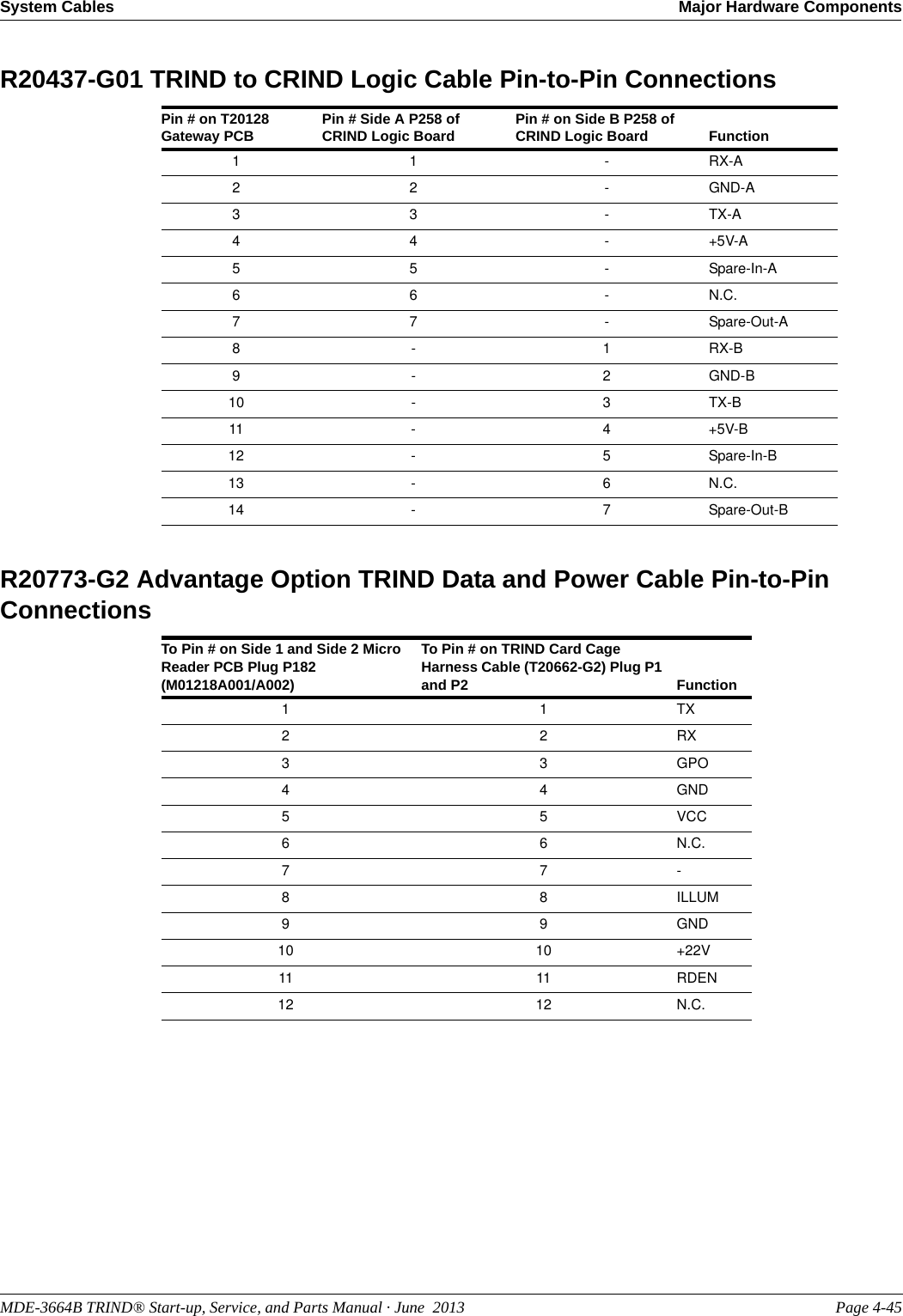
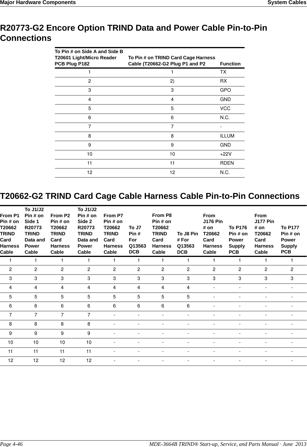
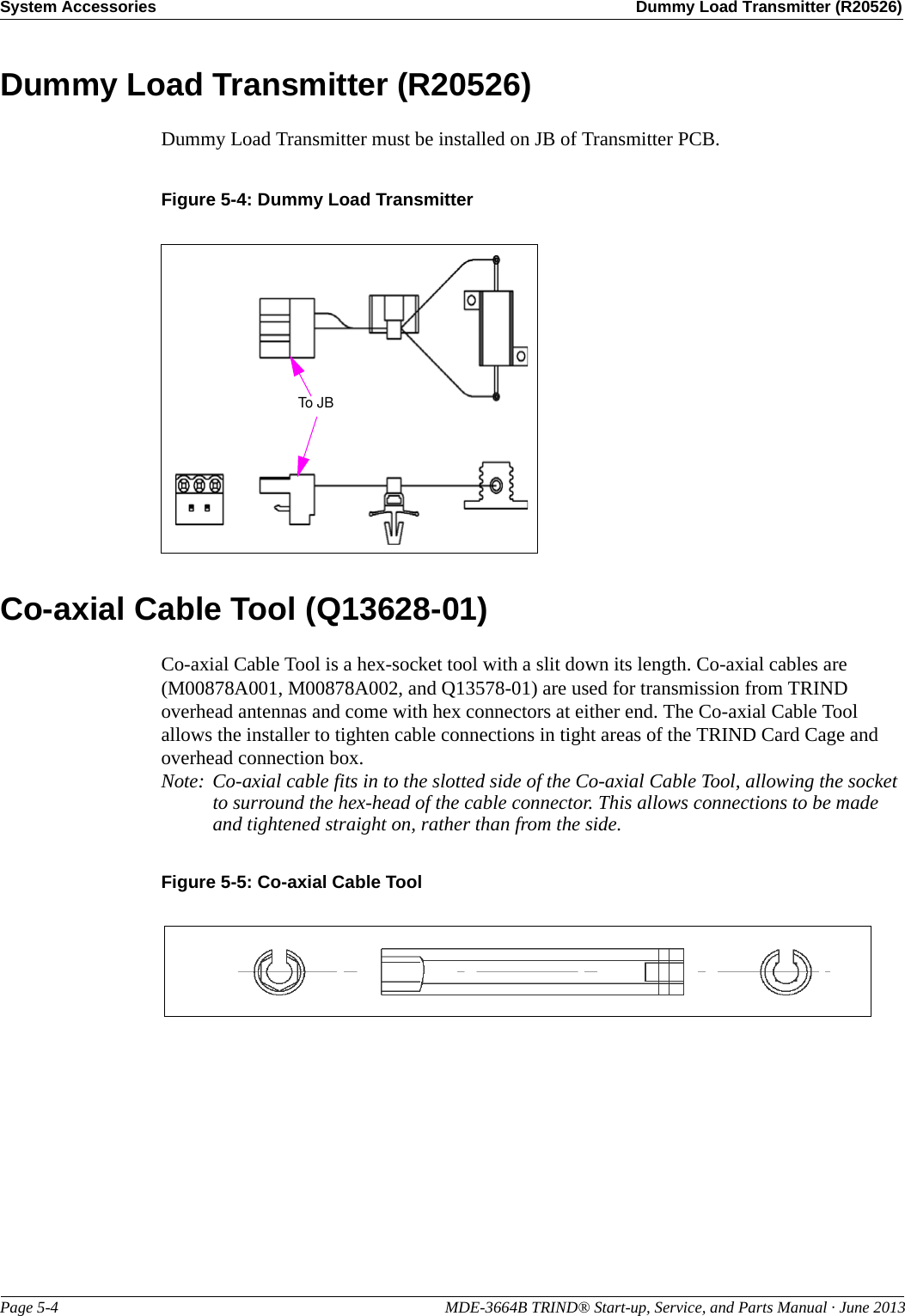
![MDE-3664B TRIND® Start-up, Service, and Parts Manual · June 2013 Page 1-5TRIND Kit Coverage IntroductionTRIND Kit CoverageFollowing table provides TRIND kit numbers and the relative system coverage that applies to each:Kit Number Product Coverage Frequencies Interface Type Tag SystemC00011-001 The Advantage Series, MPD-3LF/UHFT20229-G1 Card Cage Hand-held/Car MountedC00011-002 The Advantage Series, MPD-3LF/UHF (see note 2) T20606-G2 Card Cage Hand-held/Car MountedC00011-005 The Advantage Series, MPD-3LF (see note1) T20606-G3 Card Cage Hand-heldC00011-004 Encore 500 LF/UHF T20606-G2 Card Cage Hand-held/Car MountedC00011-006 Encore 500, Eclipse LF T20606-G3 Card Cage Hand-heldC00011-007 The Advantage Series, MPD-3LF/UHF [ETSI (see note 3)] T20606-G5 Card Cage Hand-held/Car MountedC00011-008 Encore 500 LF/UHF (ETSI) T20606-G2 Card Cage Hand-held/Car MountedC00011-009 The Advantage Series, MPD-3LF/UHF T20606-G5 Card Cage Hand-held/Car MountedC00011-010 The Advantage Series, MPD-3LF/UHFT20606-G2 Card Cage Hand-held/Car MountedC00012-00X The Advantage Series, MPD-3HF (see note 4) T20538-G1/G2 Card Cage Hand-heldNotes:1. LF = Low Frequency [LF (134 kHz)] send and receive for Hand-held Tags.2. LF/UHF = LF (134kHz) send, and Ultra-Hi Frequency [UHF (902 MHz)] receive for Car Tags. LF (134 kHz) for Hand-held Tags.3. LF/UHF (ETSI) = LF (134 kHz) send and UHF (868 MHz) receive for Car Tags. LF (134 kHz) for Hand-held Tags.4. HF = High Frequency [HF (13.56 MHz)] send and receive for Hand-held Tags.](https://usermanual.wiki/Gilbarco/LFSQR/User-Guide-2656478-Page-12.png)
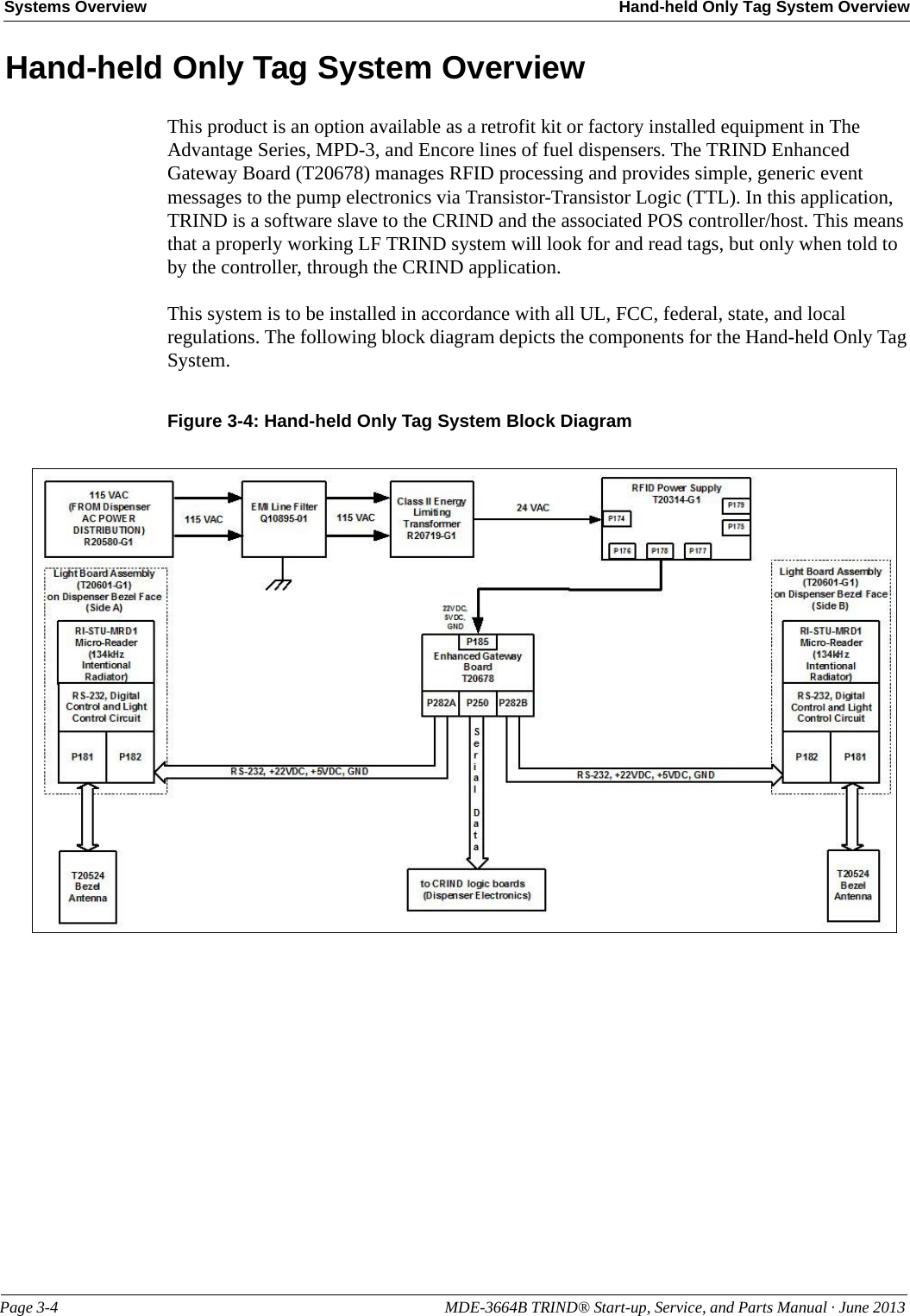
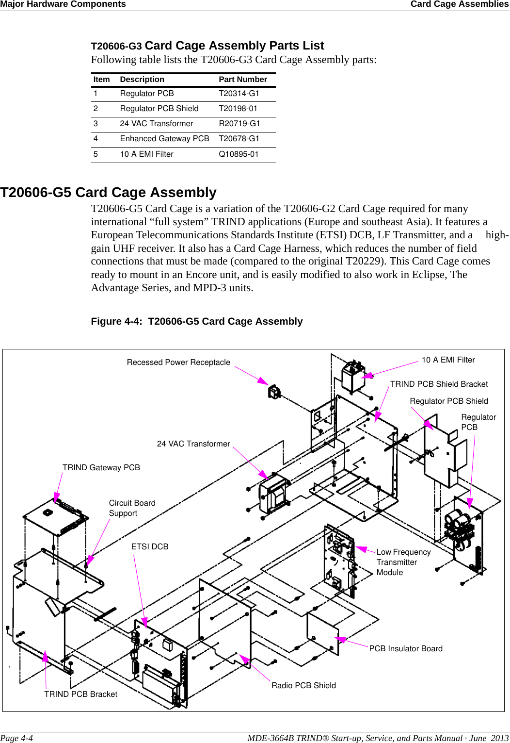
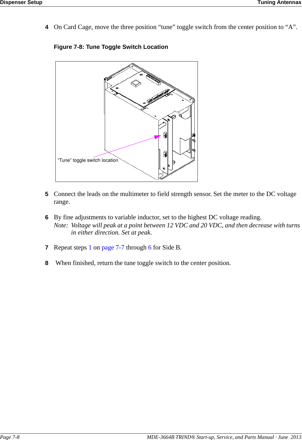
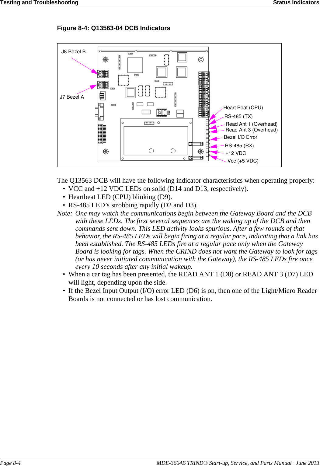
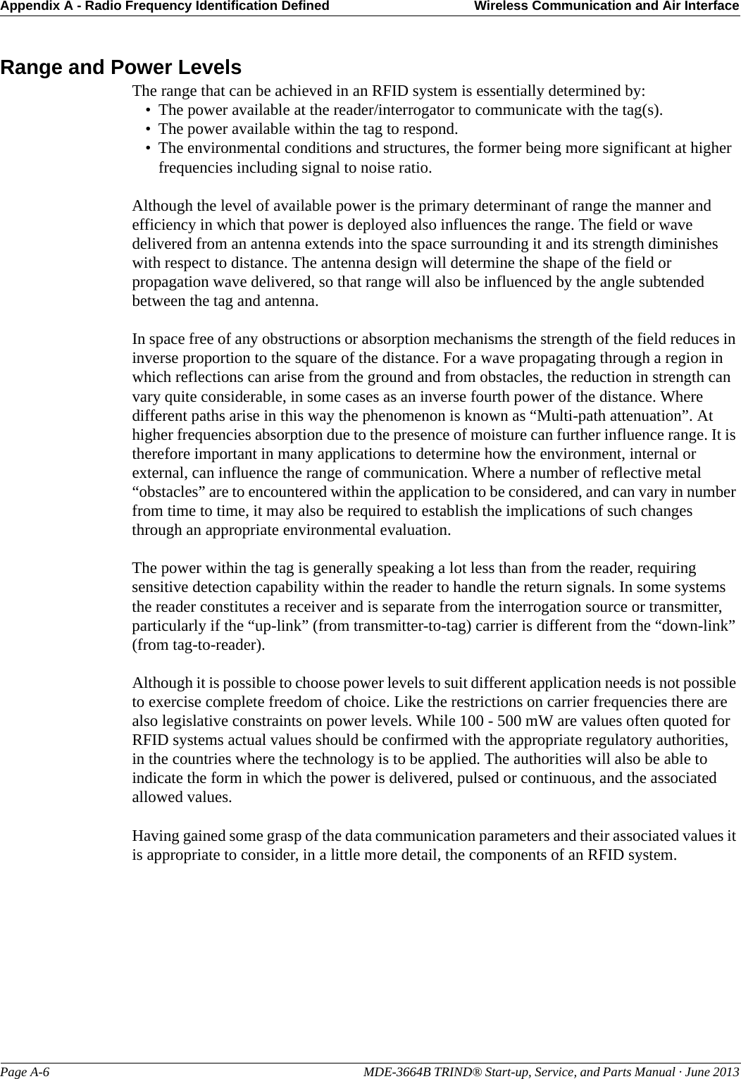
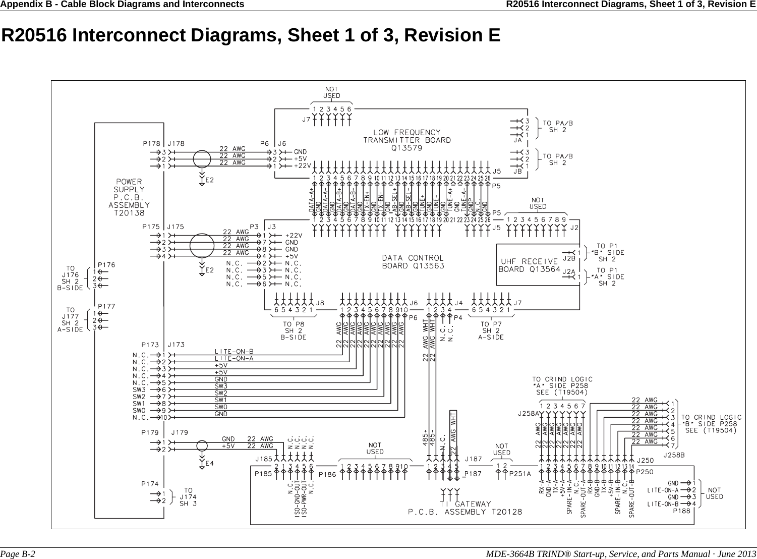
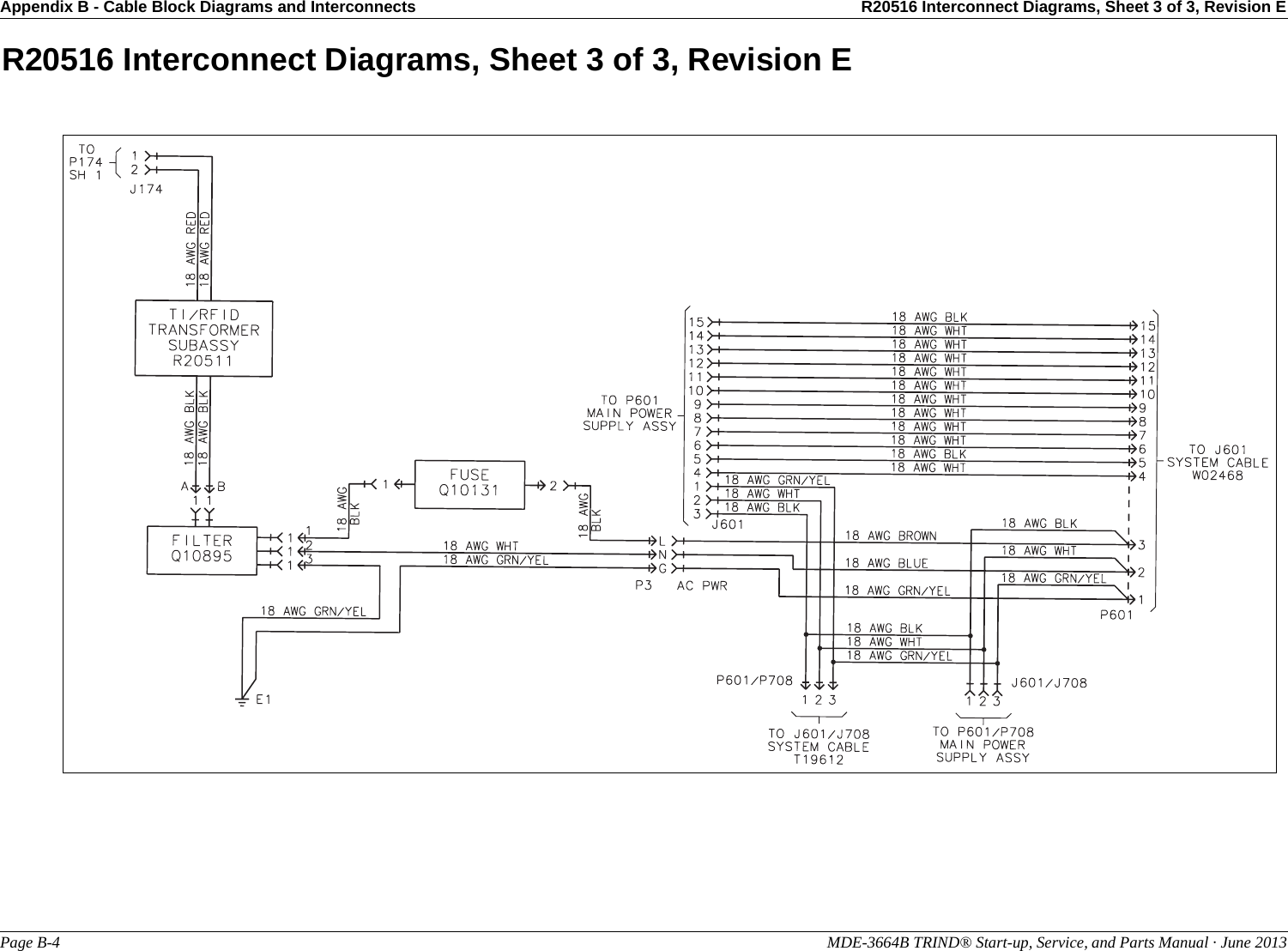
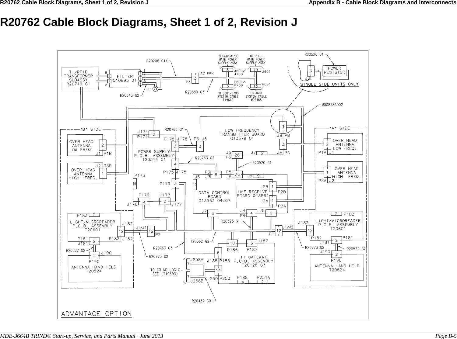
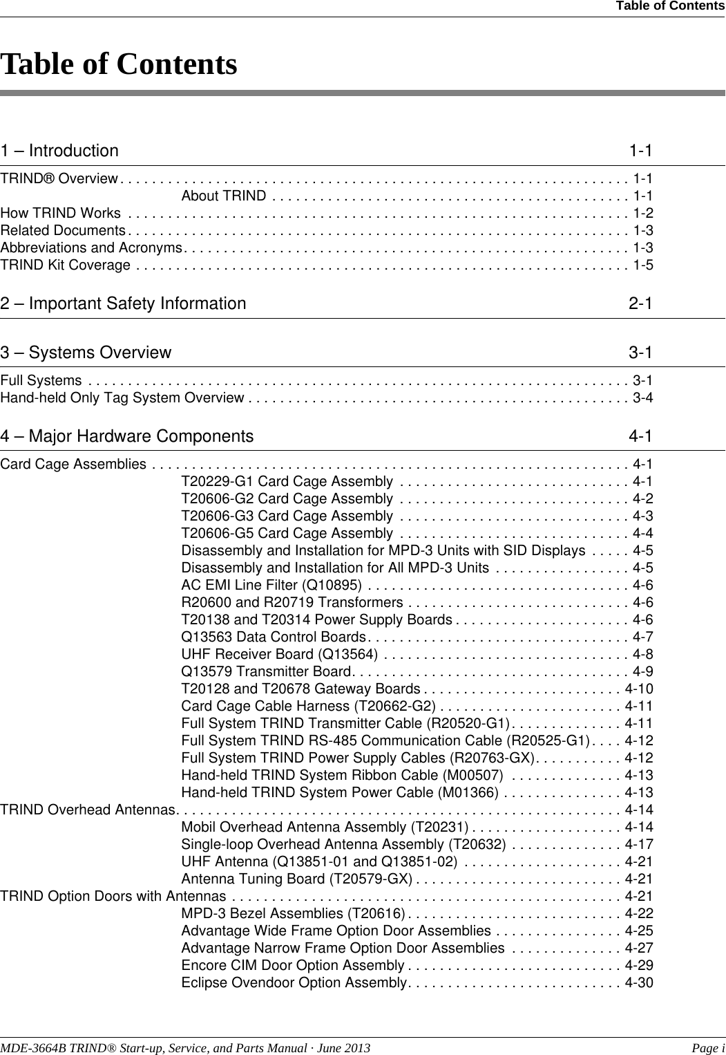
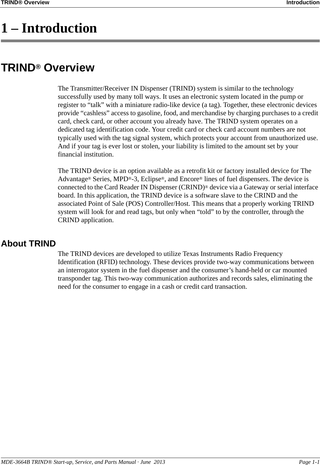
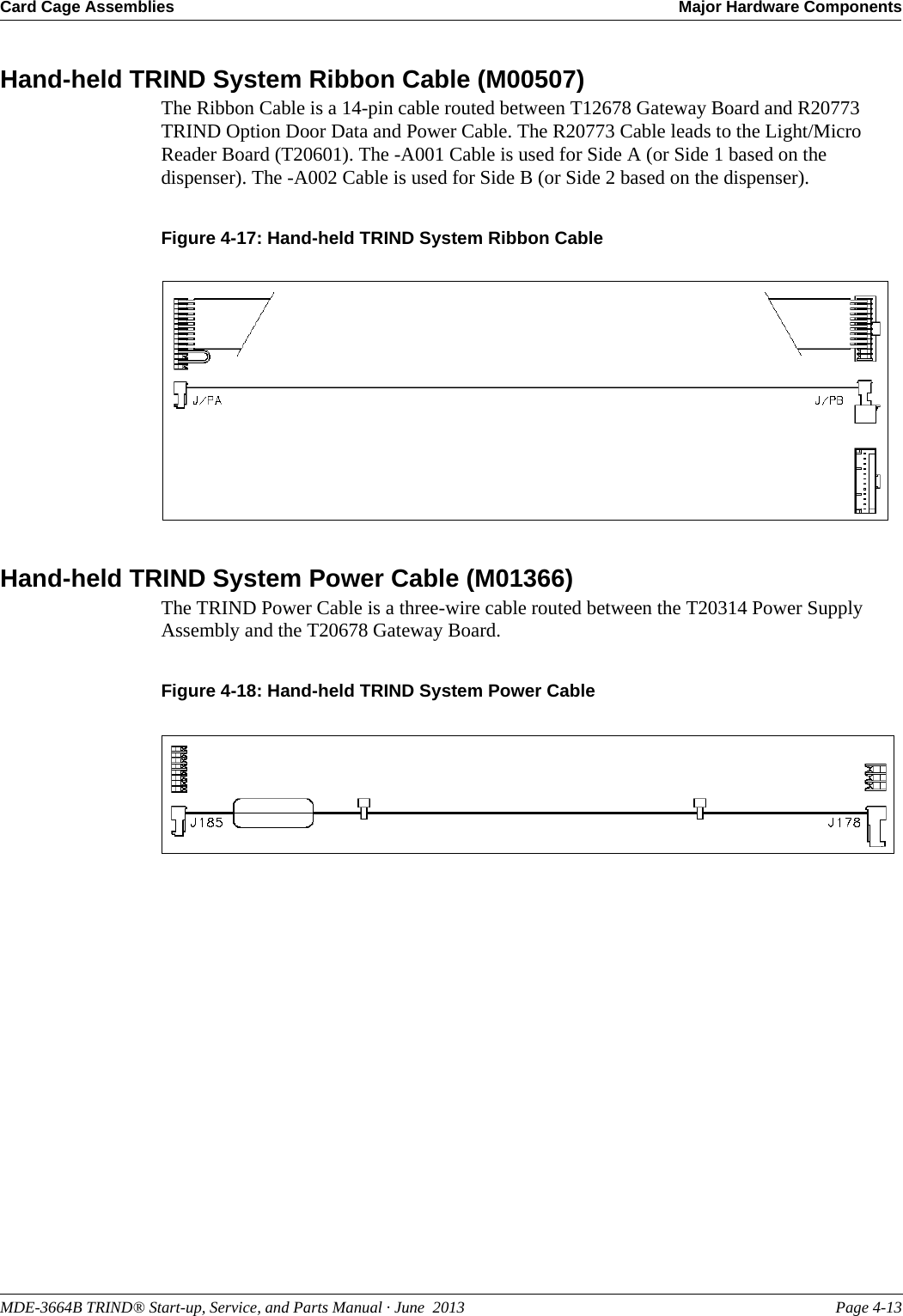
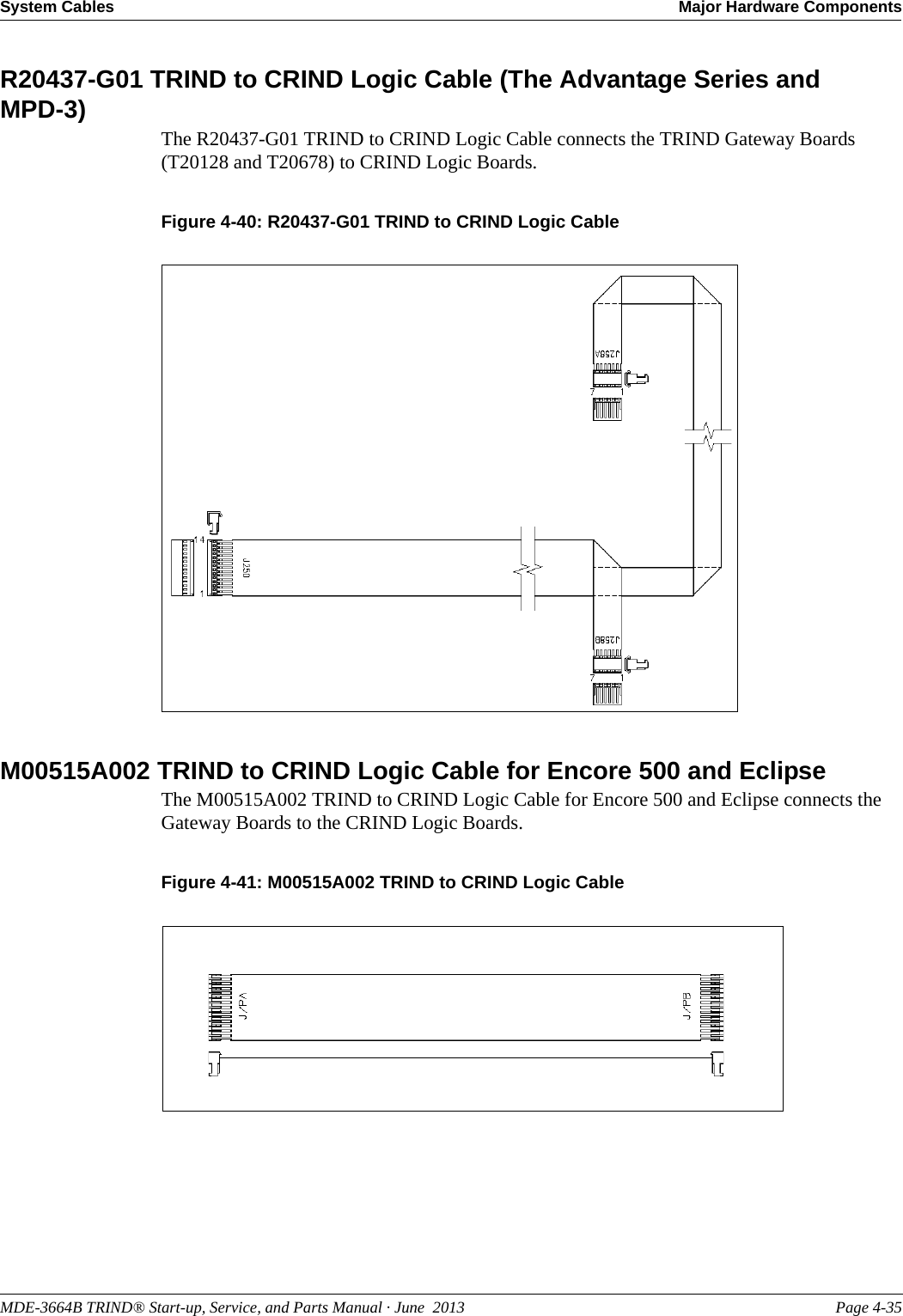
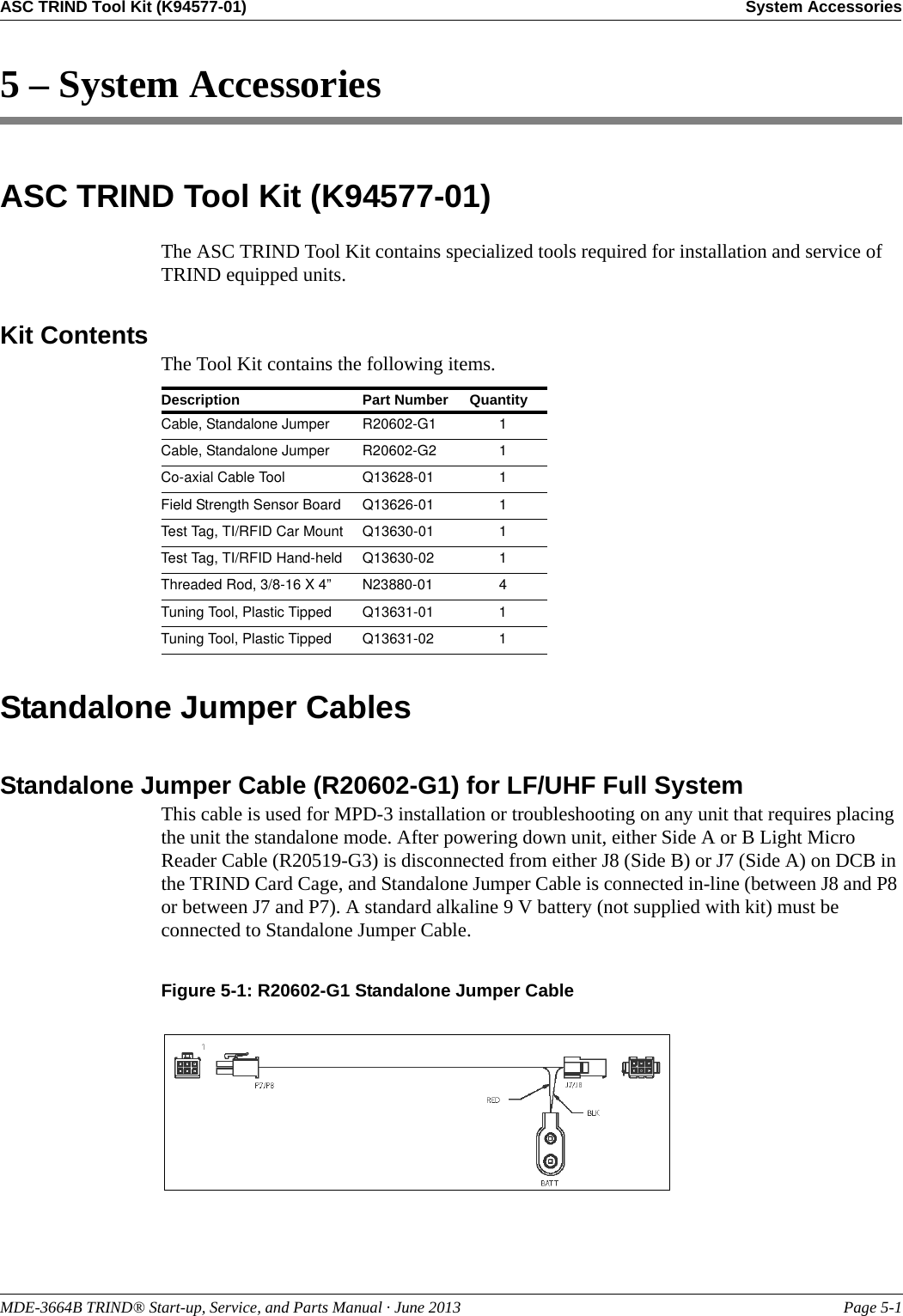
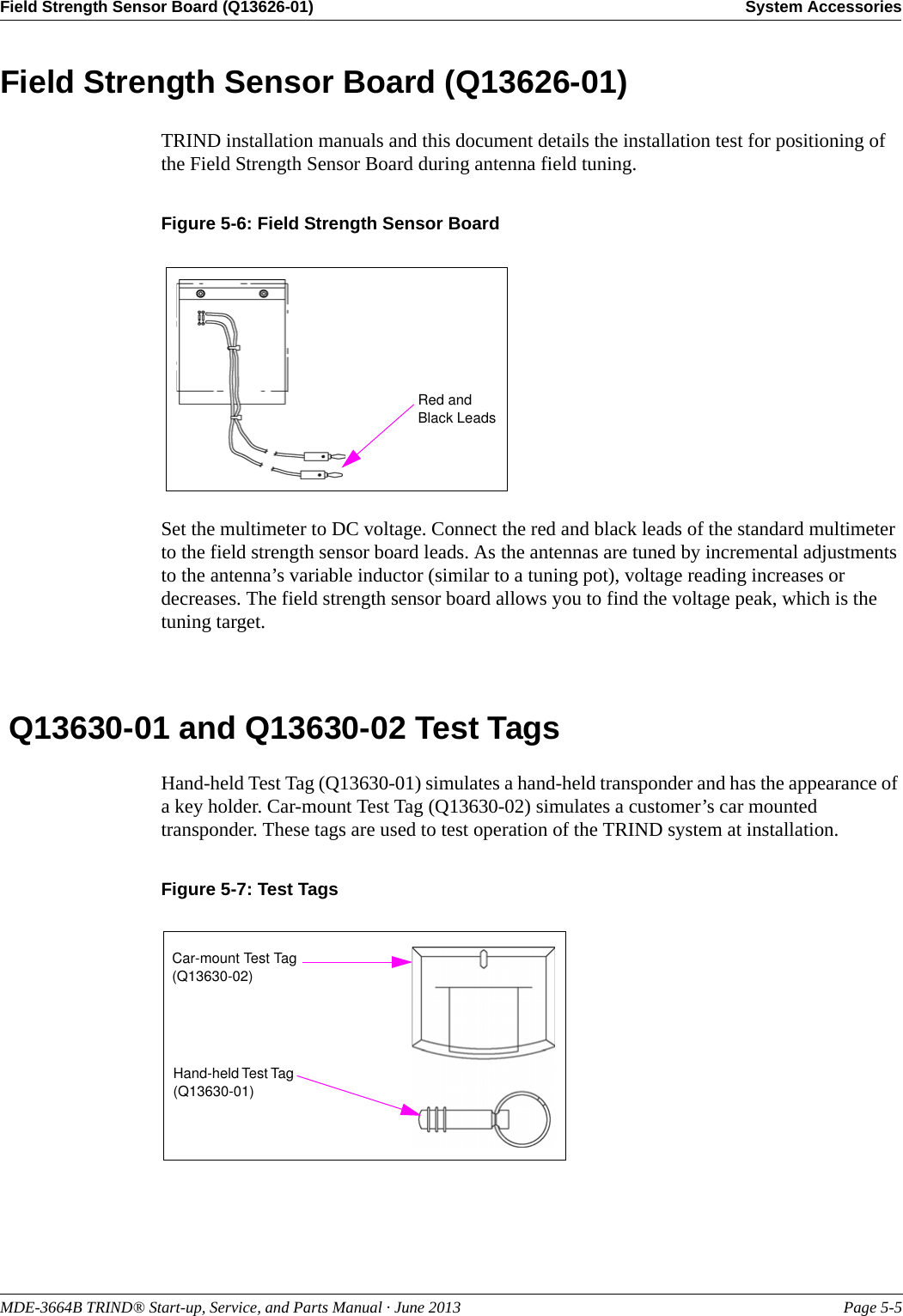
![Major Hardware Components Card Cage AssembliesPage 4-6 MDE-3664B TRIND® Start-up, Service, and Parts Manual · June 2013AC EMI Line Filter (Q10895)AC Electromagnetic Interference (EMI) Line Filter, is a Corcom dual T section RFI power line filter. These filters are well suited for low impedance loads where noisy RFI environments are present. They control pulsed, continuous and/or intermittent interference, insuring protection of the TRIND equipment from power line noise in addition to protecting the line from equipment noise.R20600 and R20719 TransformersR20600-G1 Transformer is used in the T20229-G2 Card Cage Assembly. R20719-G1 Transformer is used in the T20606-G2 LF/UHF Full System, and Enhanced Gateway System Card Cages. Each transformer performs step down of 120 VAC to a usable level for the RFID Power Supply. The R20600 steps 120 VAC down to 60 VAC, which is used by the T20138-G1 Power Supply Board. The R20719 steps 120 VAC down to 24 VAC, which is used by the T20314-G1 Power Supply Board.T20138 and T20314 Power Supply BoardsT20138-G1 Power Supply Board is used in the T20229-G1 Full System Card Cage Assembly. T20314-G1 Power Supply Board is used in T20606 line of Card Cages. The supplies take the output of their respective AC to AC transformers and make the proper Direct Current (DC) voltages for use by the TRIND system components. Both supplies utilize a gate-driven Metal-oxide-semiconductor Field-effect Transistor [MOSFET (for +22 VDC)] and a buck switched mode power supply (for +5 VDC). Both supplies monitor the current on the output to turn off the gate drive, rather than fail permanently, should one of the TRIND system components develop a voltage problem. This arrangement allows for any of the outputs to be shorted directly to ground with out harming the power supply because it turns itself off until the problem is discovered and removed, and AC power is cycled.T20138 Power Supply BoardThis board has jump-jack locations to set the dither sync (refer to “Glossary” on page 4-1) address for the TRIND unit, with a 10-position ribbon cable (at P173) that goes to the DCB (J6). These addresses only matter to the site itself, not the pump or CRIND.Figure 4-6: T20138 Power Supply Board5 VGND22 VGND GND5 V 22 VGNDNote: P176, P177, and P178 are identical.JP1 through JP4: must be unique address for each dispenser at site22 V 5 V5 V](https://usermanual.wiki/Gilbarco/LFSQR/User-Guide-2656478-Page-27.png)
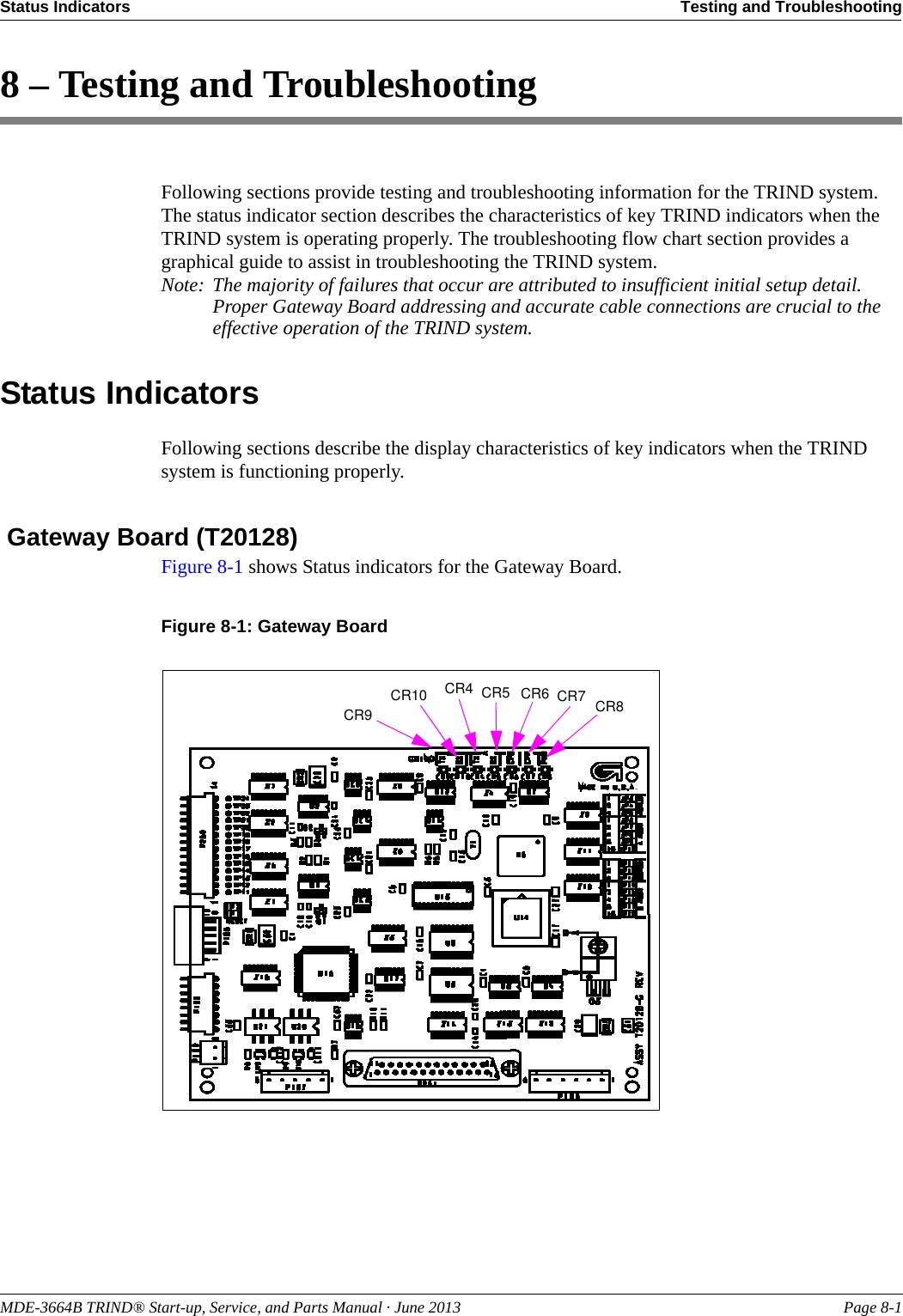
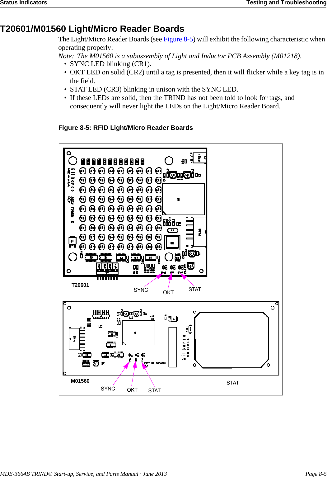
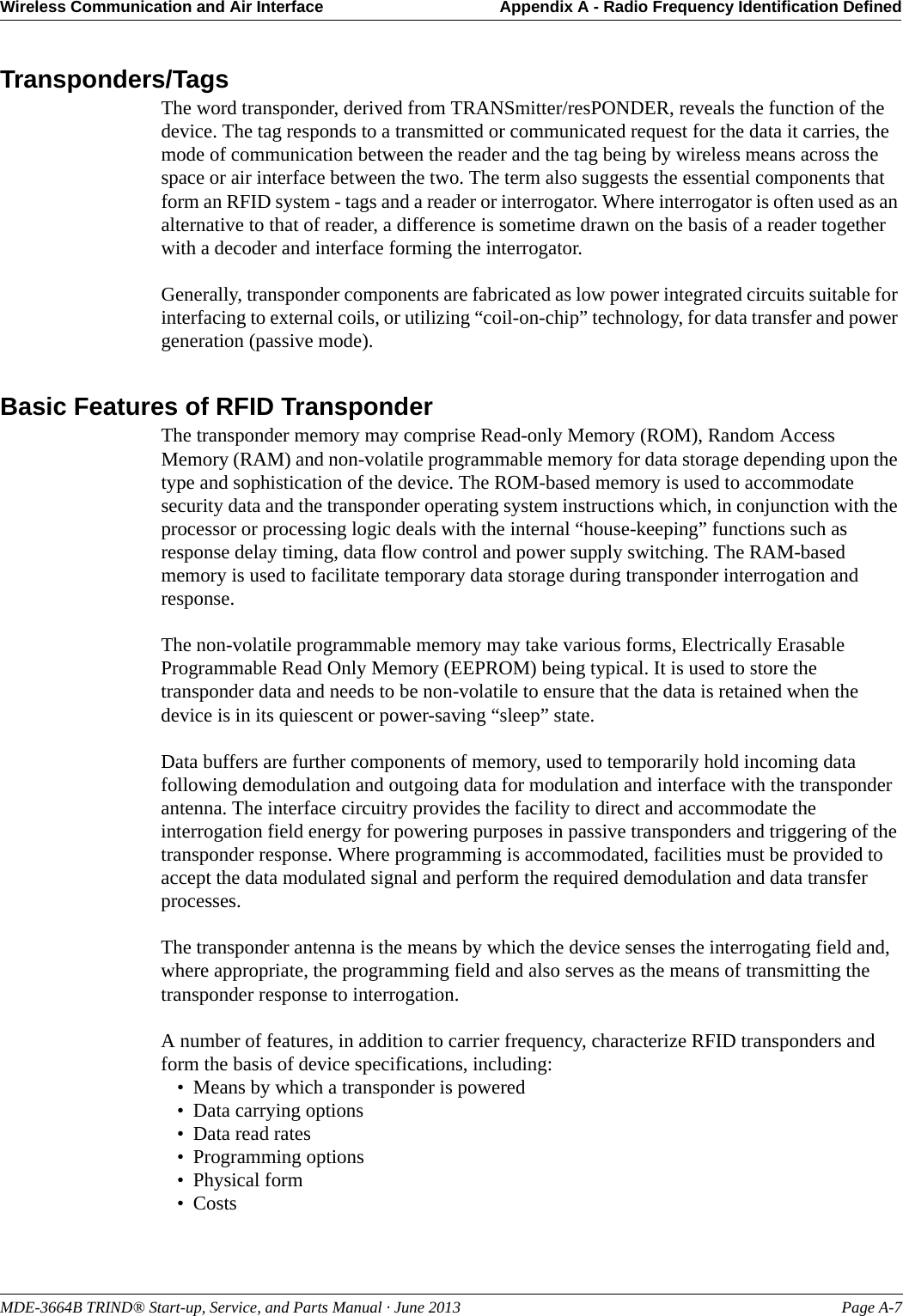
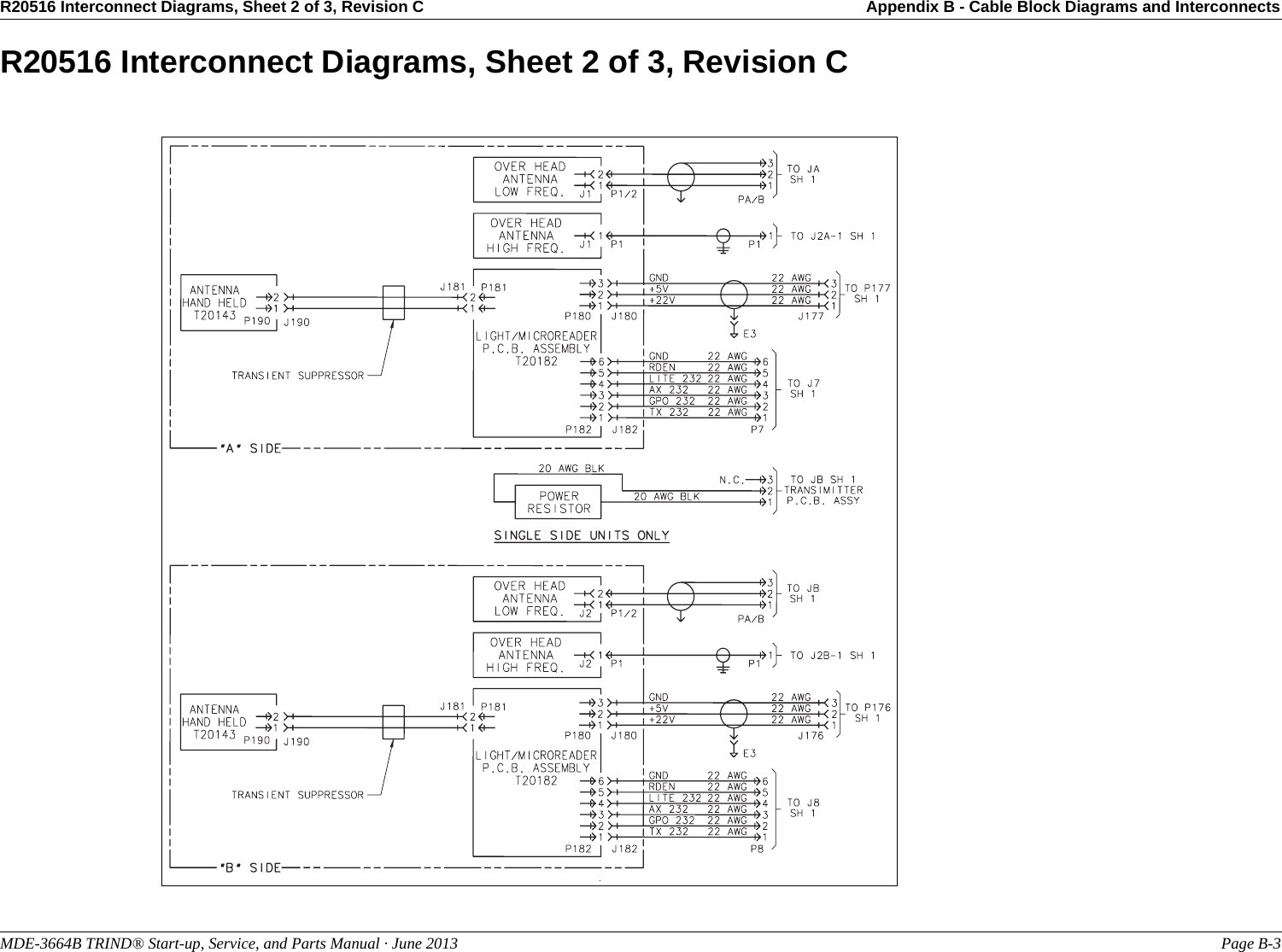
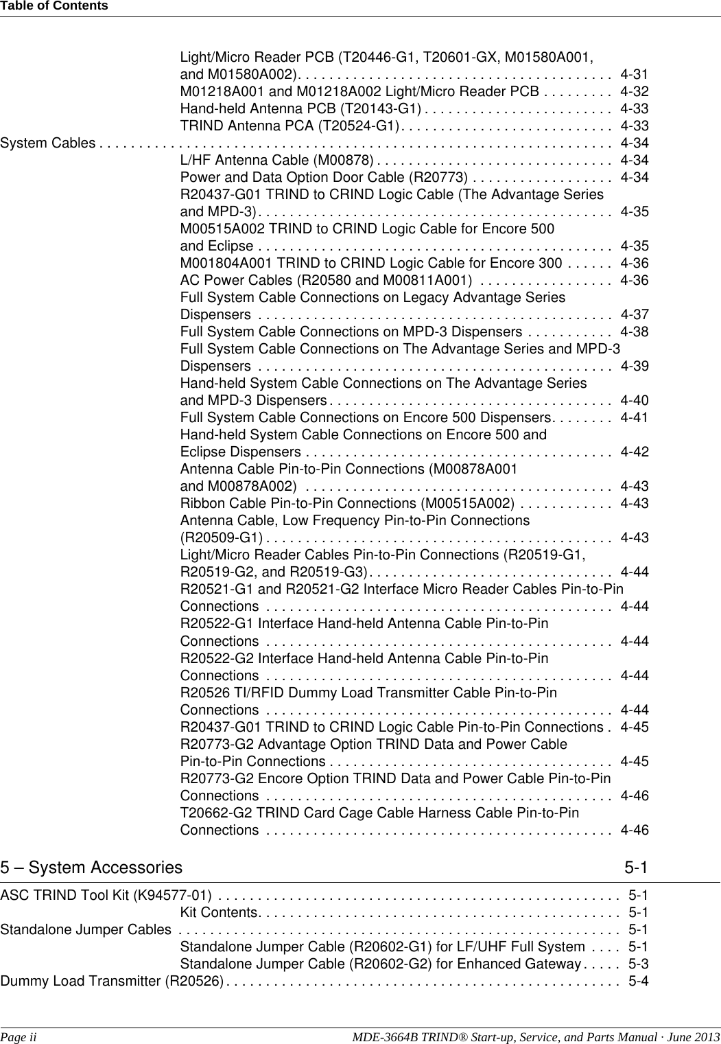
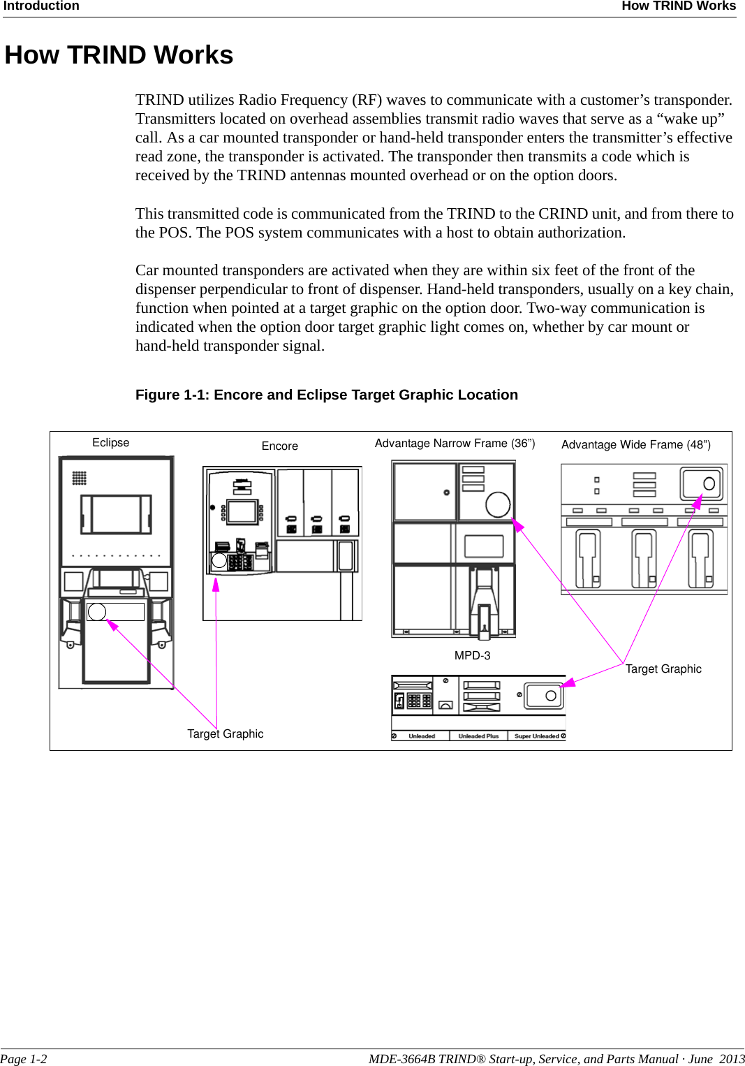
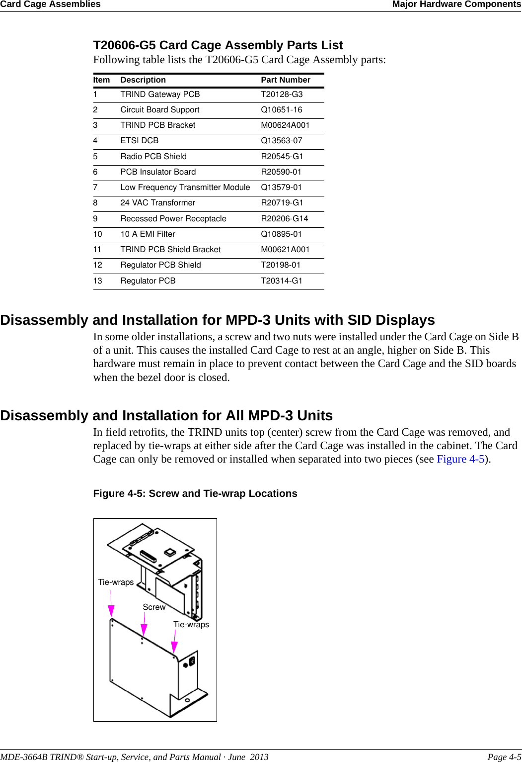
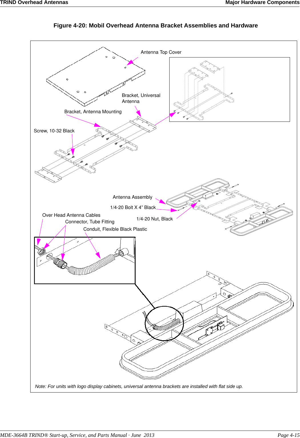
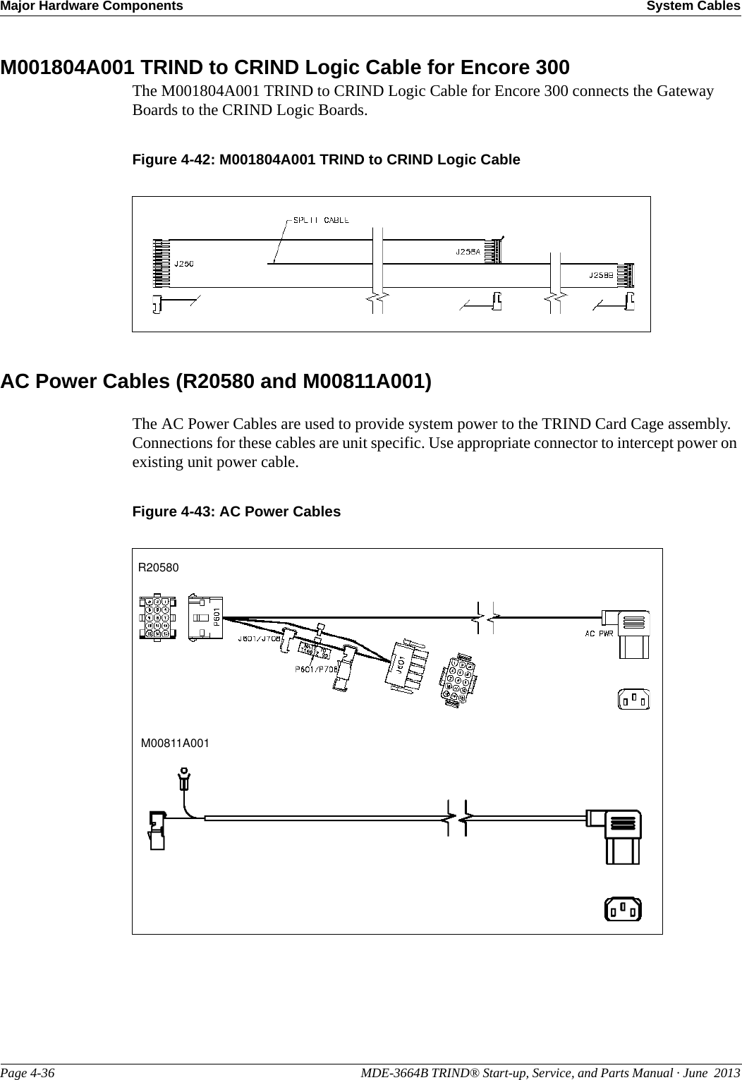
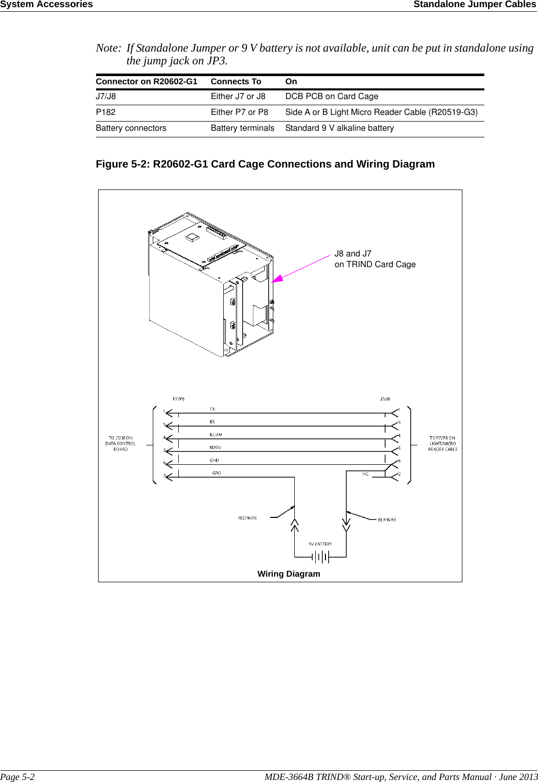
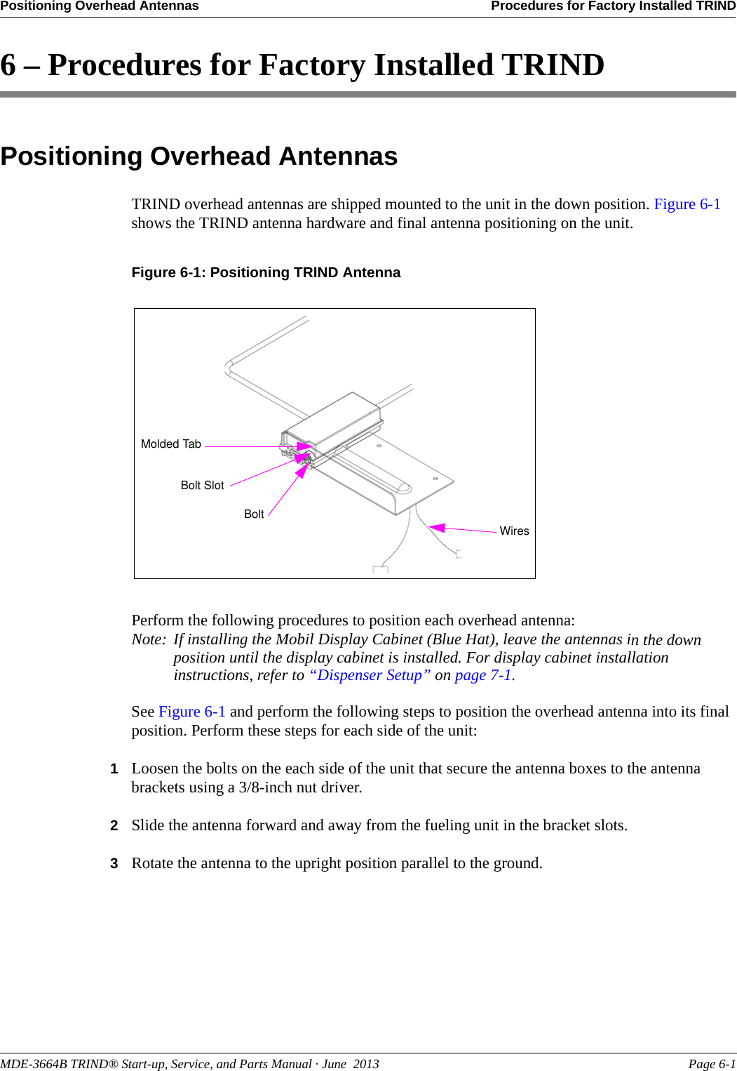
![Major Hardware Components TRIND Overhead AntennasPage 4-14 MDE-3664B TRIND® Start-up, Service, and Parts Manual · June 2013TRIND Overhead AntennasFull System TRIND has six antennas, four active and two passive. The active antennas can further be divided as transmit only (overhead antennas), and transmit and receive [option door/Customer Interface Module (CIM) door antennas]. All four operate in the LF band at 134.2 kHz. The two passive antennas receive in the UHF Band at 902 MHz (in the US) and at 868 MHz (Asia and Europe), and are used in conjunction with the overhead antennas to utilize the car tags. There are two basic variations of the full system TRIND. The fundamental differences are based on the Card Cage and the overhead antennas used. The antennas can be divided into two sections, the original Mobil antennas (no longer available) and the single-loop antennas, which are currently being shipped with full system TRIND.Mobil Overhead Antenna Assembly (T20231)The Mobil overhead antenna assembly consists of a multiple loop (47 uH) coil for LF transmission, a tuning board, and sheet metal slot antenna for UHF receive. This assembly is no longer available, but is still a part of the installed base at Mobil Stations. These antennas have been replaced by the T20632 family of Overhead Antennas.Figure 4-19: Mobil Overhead Antenna AssemblyTuner GasketTuner CoverTuning BoardMolded Antenna902.858 MHz HF Antenna, 868.4 MHz HF AntennaMobil Overhead Antenna AssemblyFollowing table lists the Mobil Overhead Antenna Assembly parts:Item Description Part Number1902.858 MHz HF Antenna Q13580-012868.4 MHz HF Antenna Q13580-023Molded Antenna Q13582-014Tuning Board Q13582-025Tuner Gasket Q13582-046Tuner Cover Q13582-03](https://usermanual.wiki/Gilbarco/LFSQR/User-Guide-2656478-Page-35.png)
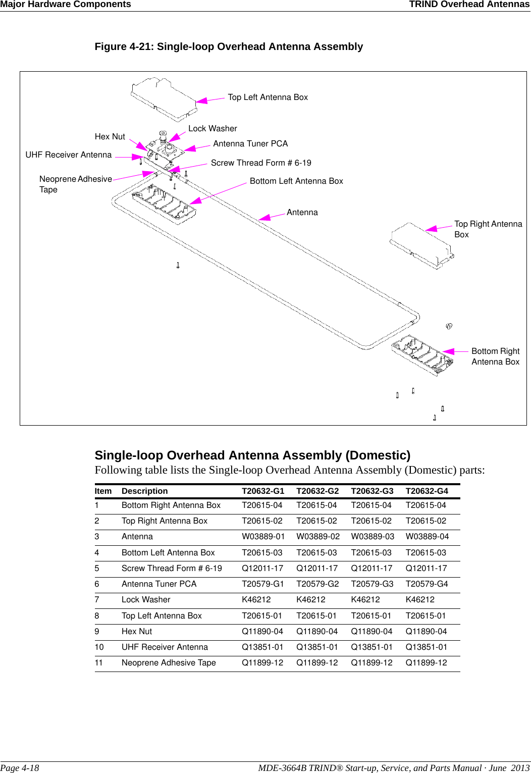
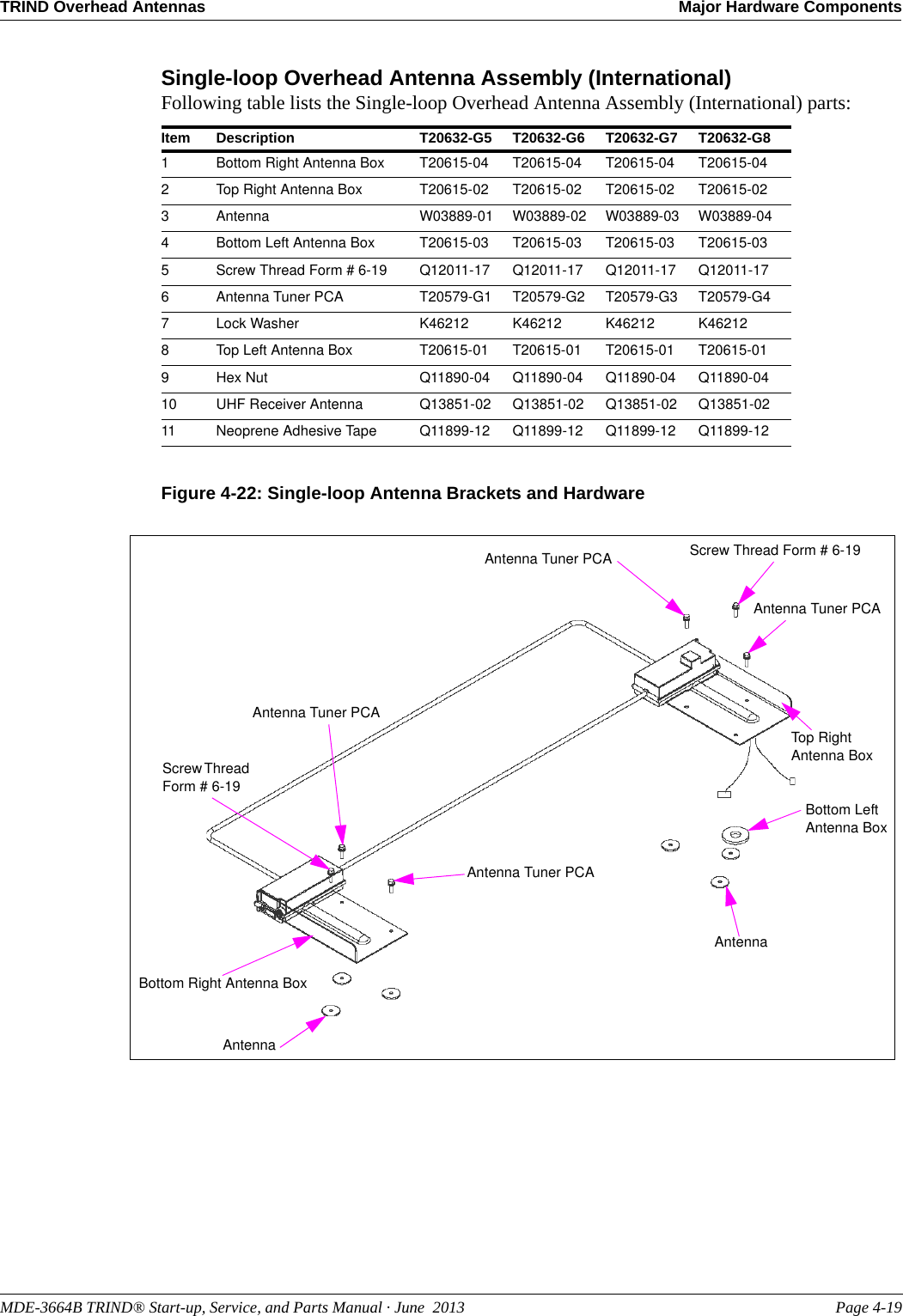
![MDE-3664B TRIND® Start-up, Service, and Parts Manual · June 2013 Page 4-17TRIND Overhead Antennas Major Hardware ComponentsSingle-loop Overhead Antenna Assembly (T20632)The Single-loop Overhead Antenna Assemblies (T20632-GX) are made up from a single turn (loop) antenna; a high-efficiency tuning board, and a UHF receive antenna. These parts are all mounted in a molded polycarbonate set of boxes and then mounted with brackets on top of the dispenser. These parts are discussed in further in the following sections.Note: There are eight different “G” levels of this antenna assembly, due to the different widths and heights of the dispensers. T20632 “G” Level Dispenser Antenna is used G1/G5 Advantage Wide Frame and MPD-3G2/G6 Advantage Narrow FrameG3/G7 EncoreG4/G8 Advantage Wide Frame with Exxon® Light BoxSMA connections should be treated with care and not overtightened. The maximum torque rating on these connectors is usually measured in inch poundsToo severe a turn or bend in the cable may damage the center conductor or compromise the shield/drain portion of the cable. This can result in an observance of intermittent reads or other problems. The poor performance will in turn generate a premature field service call. Replacing this cable is labor intensive after the system is installed the first time.Turns or bends in co-axial cable must be gradual loops, no sharper than a 1-inch radius (2-inch diameter).CAUTIONCAUTIONIt is critical that the proper tool is used when tuning the overhead antennas on TRIND systems. Only the Q13631-02 [part of Authorized Service Contractor (ASC) Tool Kit K94577-01] plastic tuning tool (or similar plastic 0.10-inch hex tool) should be used for tuning overhead antennas. Using a metal screwdriver or Allen® wrench has two negative effects. First, a proper tuning is impossible as the metal of the tool used changes the properties of the variable inductor used for tuning. Second, the ferrite slug used in the variable inductor is extremely brittle and is broken or stripped easily by metal tools, preventing the proper tuning of the antenna. If the antenna is not properly tuned the read range can be significantly reduced.](https://usermanual.wiki/Gilbarco/LFSQR/User-Guide-2656478-Page-38.png)
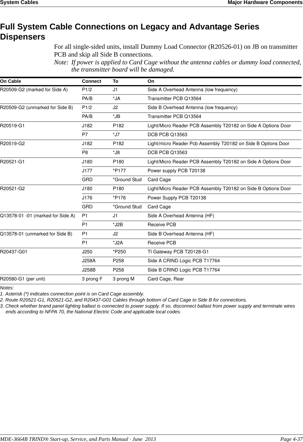
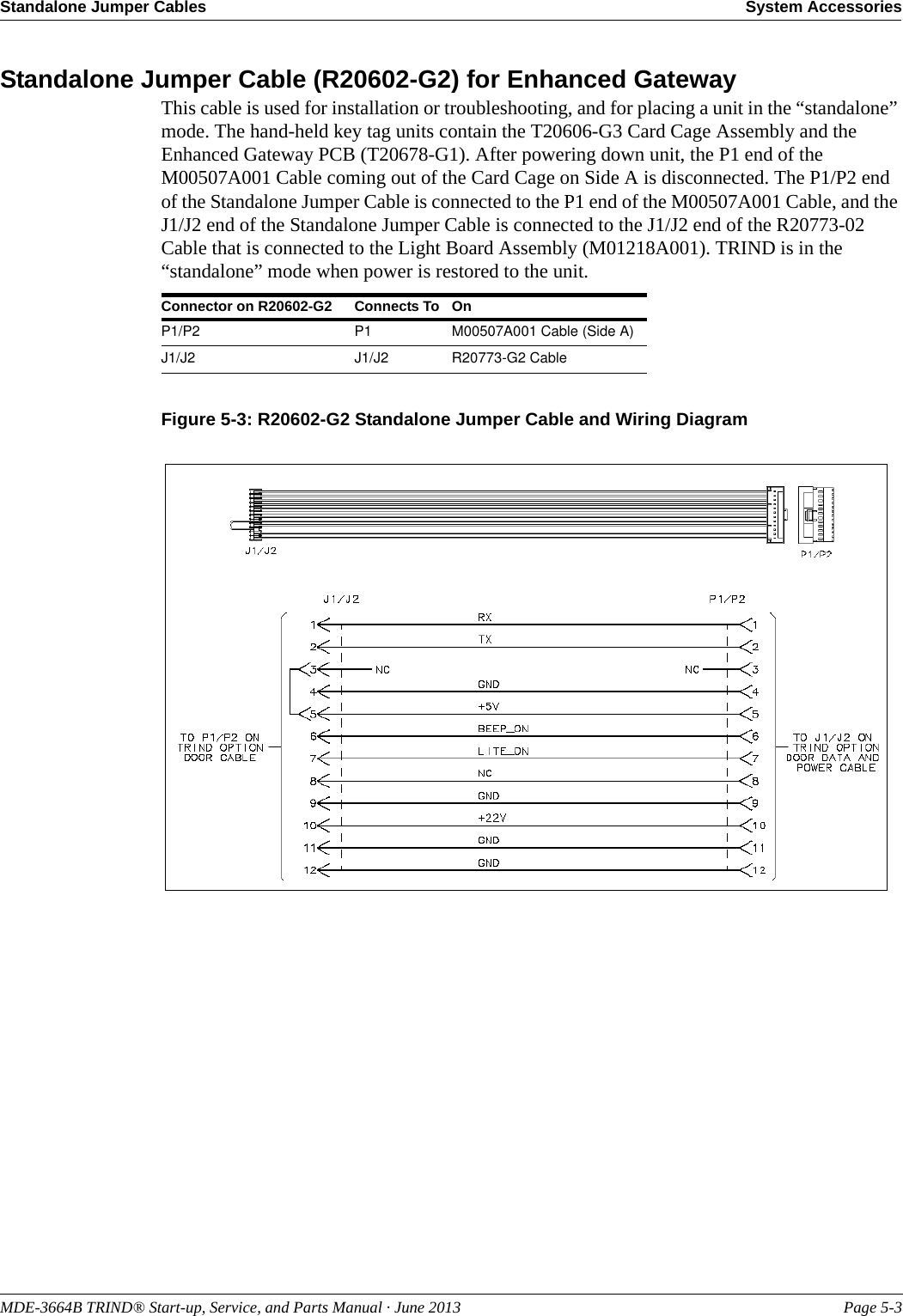
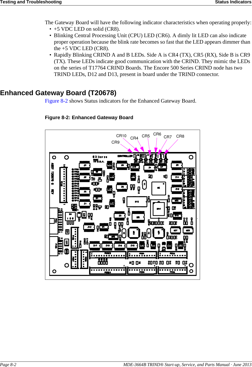
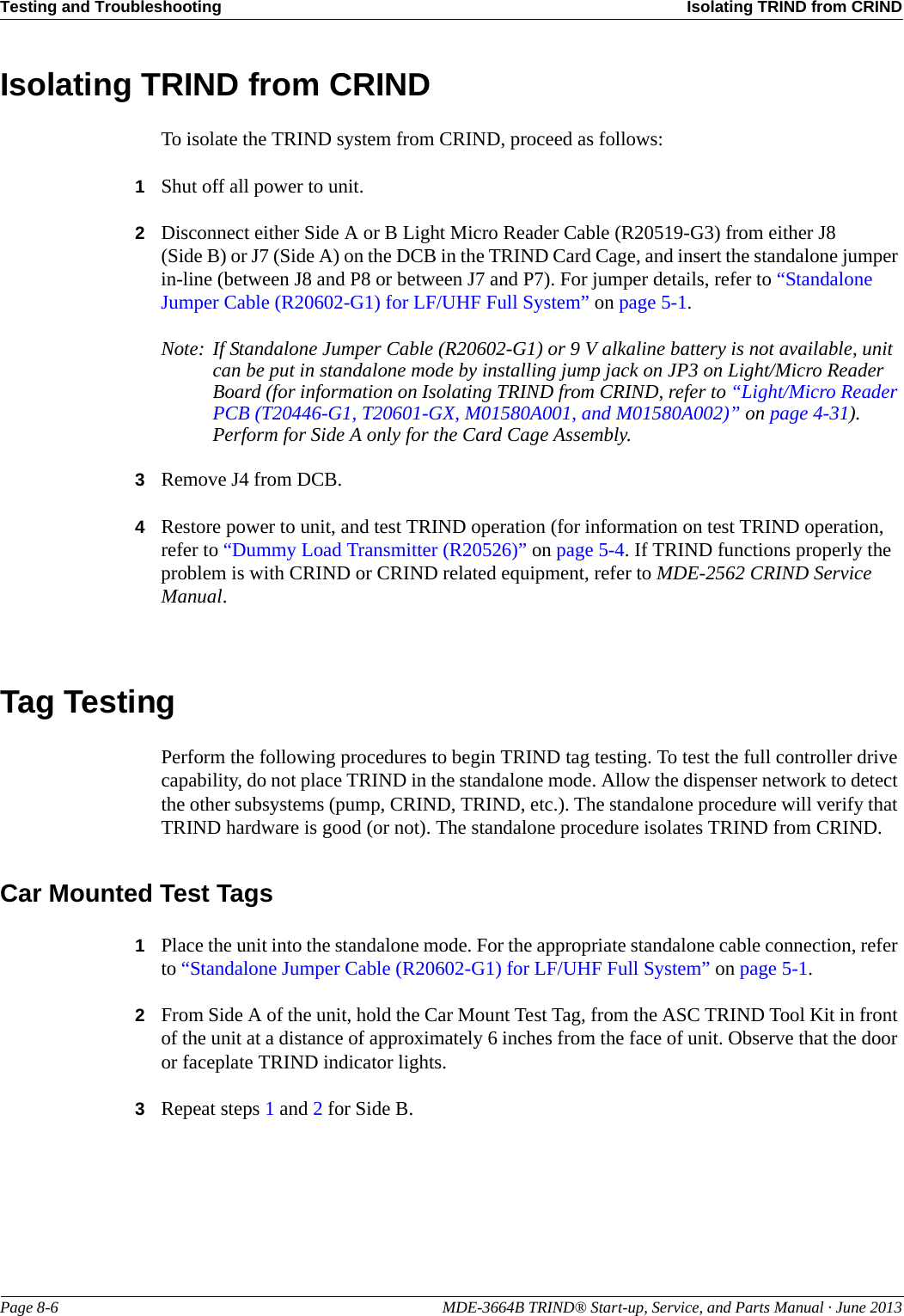
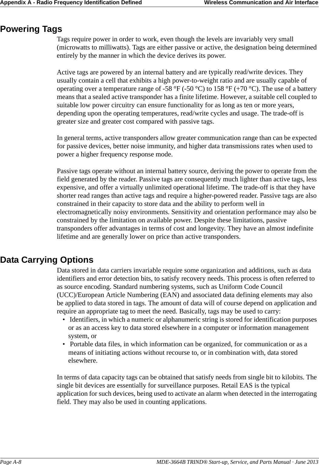
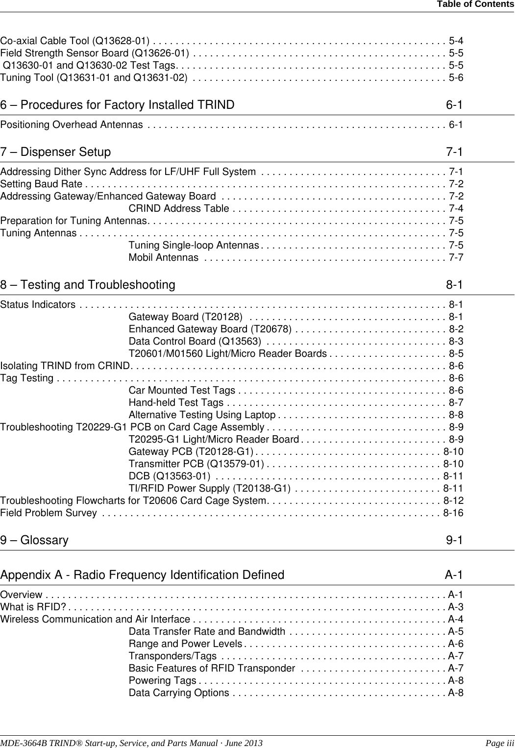
![System Accessories Tuning Tool (Q13631-01 and Q13631-02)Page 5-6 MDE-3664B TRIND® Start-up, Service, and Parts Manual · June 2013Hand-held Test TagDuring testing, the Hand-held tag is placed against the TRIND target on either the right options door on The Advantage Series, or on the faceplate target located on the right side of MPD-3 bezel doors.Note: Use of the test tags will cause a properly installed and operating TRIND system’s target logo to light, indicating successful reading. An actual sale is not possible with these tags.Car-mount Test TagCar-mount test tag is positioned properly when it is 6 feet from the overhead antennas and in a position that approximates that of a car’s dashboard at the fuel island.Note: The car tag has a replacable battery that has a life of two to three years.Tuning Tool (Q13631-01 and Q13631-02Only the Plastic Tuning Tool [Q13631-01 (or similar plastic 0.10-inch hex tool)], which is a part of ASC Tool Kit (K94577-01) must be used for tuning overhead antennas. Using a metal screwdriver or Allen wrench has two negative effects. First, proper tuning is impossible as the metal of the tool used changes the properties of the variable inductor used for tuning. Secondly, the ferrite slug used in the variable inductor is extremely brittle and is broken or stripped easily by metal tools, preventing the proper tuning of the antenna. If the antenna is not properly tuned, the read range can be significantly reduced.CAUTION)In conjunction with Field Strength Sensor Board (Q13626-01), tuning tools are used to make variable inductor adjustments to tune the overhead antennas. The tools are plastic and non-reactive to the variable inductor or board on the overhead antennas, and should only be used to adjust variable inductor.Figure 5-8: Tuning Tools Q13631-01Q13631-02Variable InductorQ13582-02T20579-GXThe Q13631-01 plastic flat-blade is used the same as a screwdriver. It is used with Q13582-02 and fits the slotted head of the variable inductor located on the overhead antenna PCB.The Q13631-02 plastic blade is used the same as an Allen wrench. The wrench is used with Antenna Tuning Board (T20579-GX) and fits the Allen head of the variable inductor located on the Overhead Antenna PCB (T20579-GX, located in T20632-GX Assemblies).](https://usermanual.wiki/Gilbarco/LFSQR/User-Guide-2656478-Page-73.png)
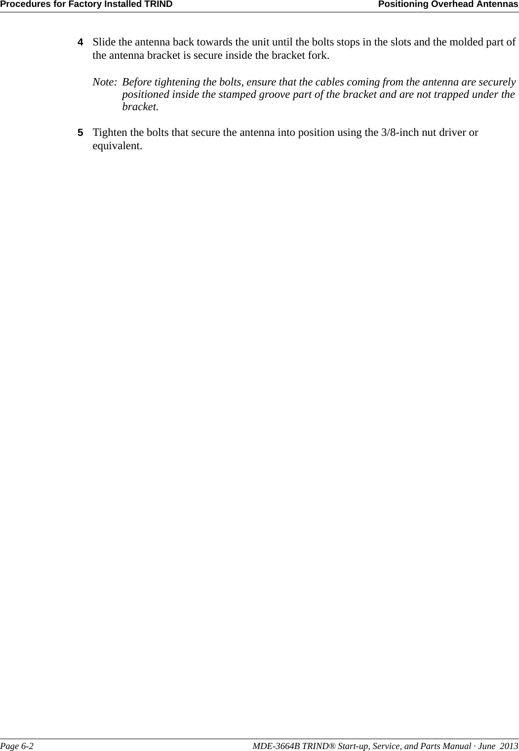
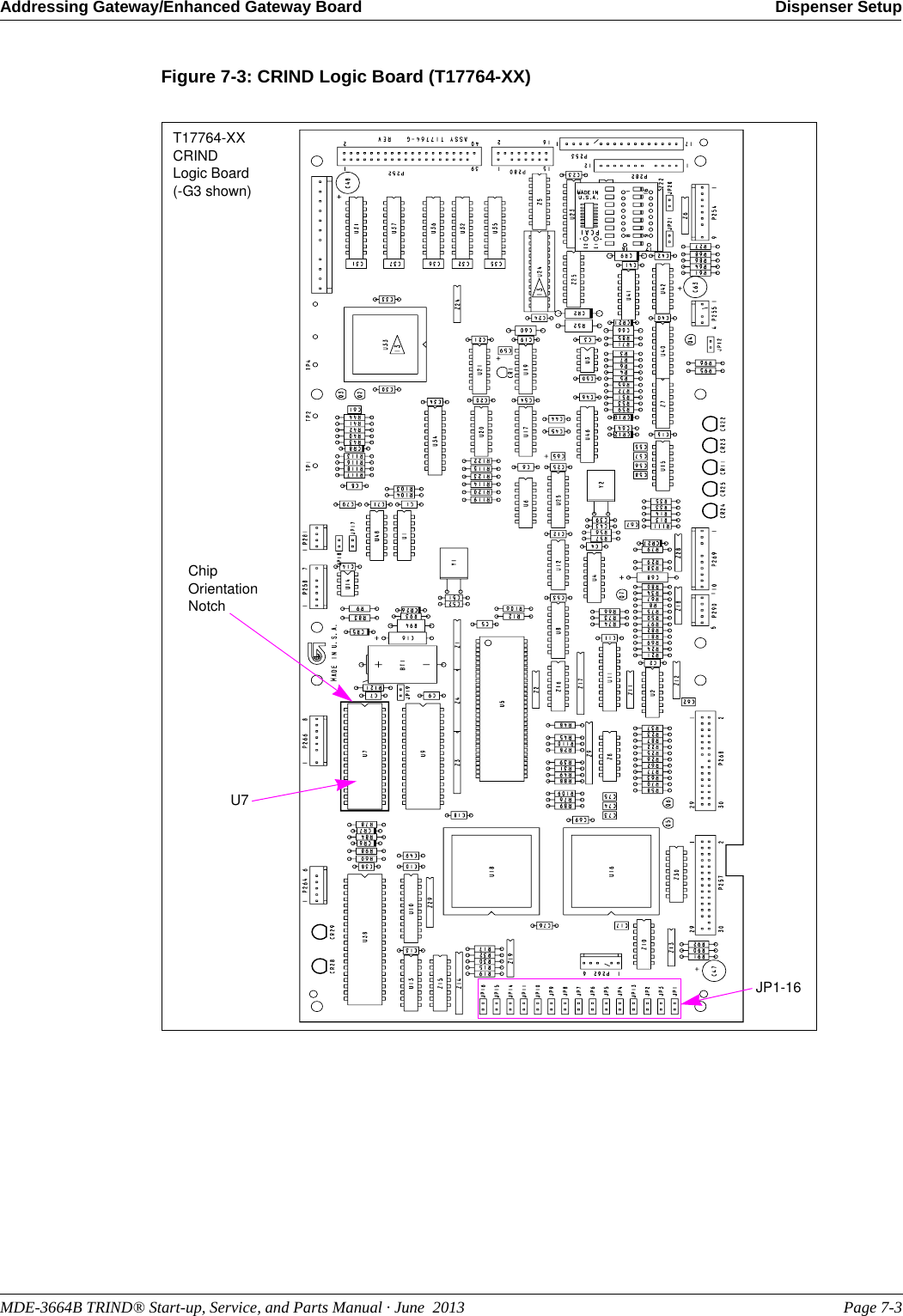
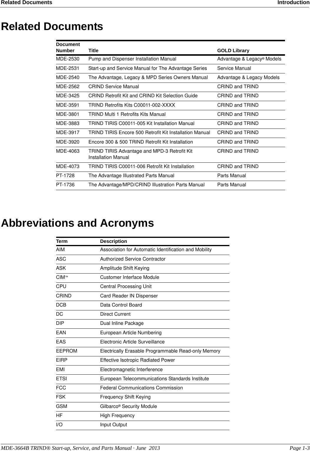
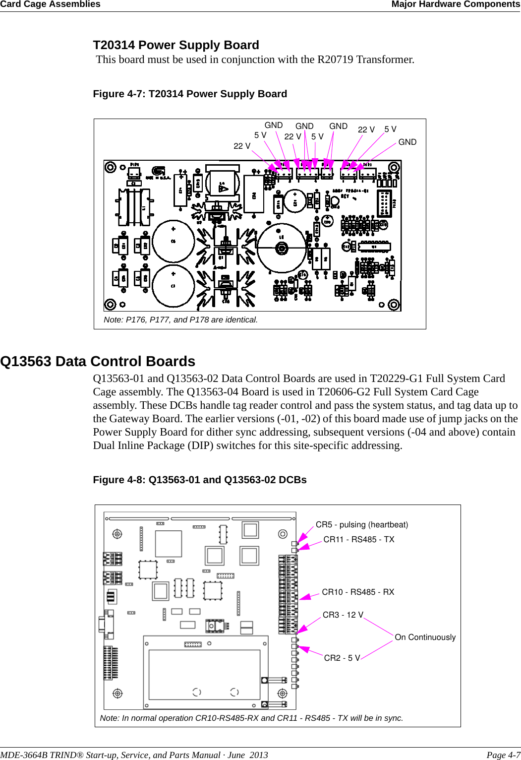
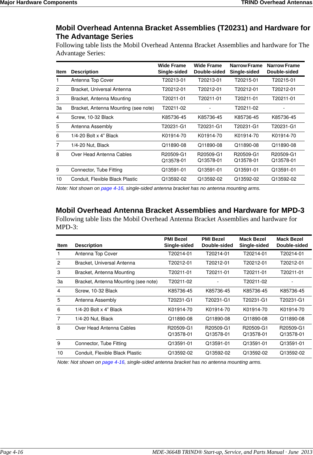
![Dispenser Setup Setting Baud RatePage 7-2 MDE-3664B TRIND® Start-up, Service, and Parts Manual · June 2013Setting Baud RateFor Major Oil Company (MOC) TRIND installations, there is no requirement to set or change baud rate.Addressing Gateway/Enhanced Gateway BoardAddresses for the TRIND device must match the addresses on CRIND Logic Board.1Access the unit’s CRIND Logic Board. Refer to MDE-2562 CRIND Service Manual.2Locate jump jacks on A and B side CRIND Logic Boards [T17764-XX (see Figure 7-3 on page 7-3)].3Note position of jump jacks and set jump jacks on Gateway/Enhanced Gateway Board (see Figure 7-2) to match address on CRIND Logic Boards (see Figure 7-3 on page 7-3) for both Sides A and B.Note: The Gateway Boards are assessable at the upper left hand corner at the front of the Card Cage.Figure 7-2: Gateway Boards Jump Jack LocationsJump Jack Locations on Enhanced Gateway Board (T20678)Jump Jack Locations on Gateway Board (T20128)](https://usermanual.wiki/Gilbarco/LFSQR/User-Guide-2656478-Page-77.png)