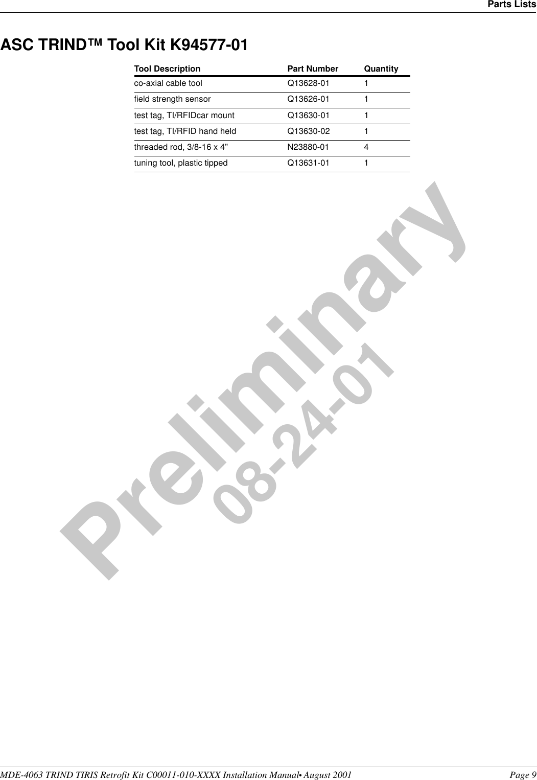
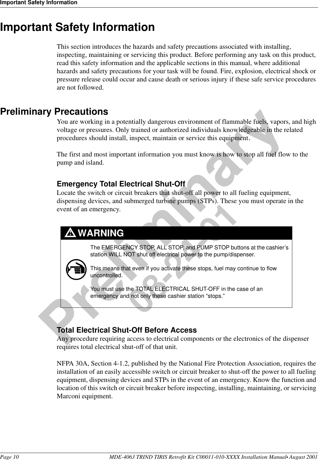
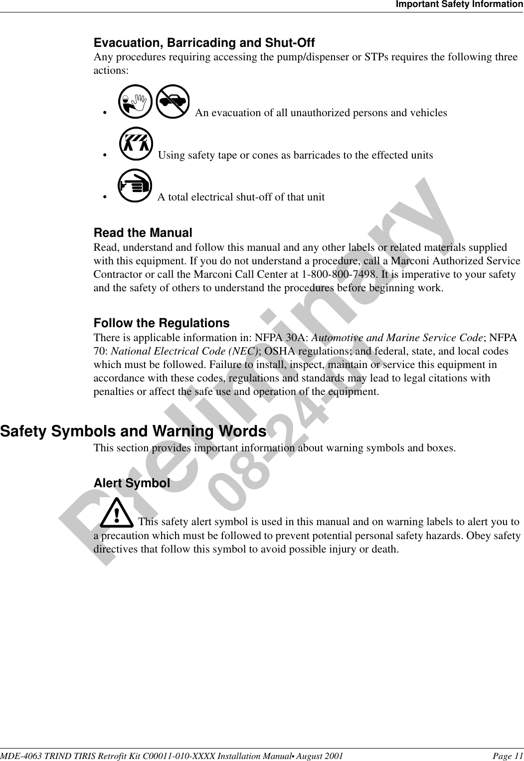
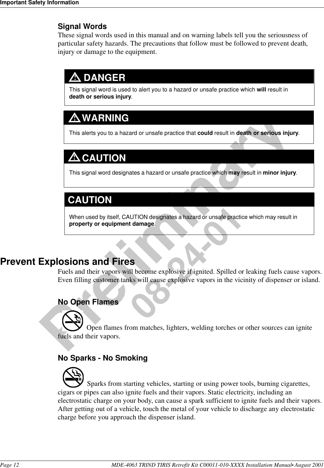
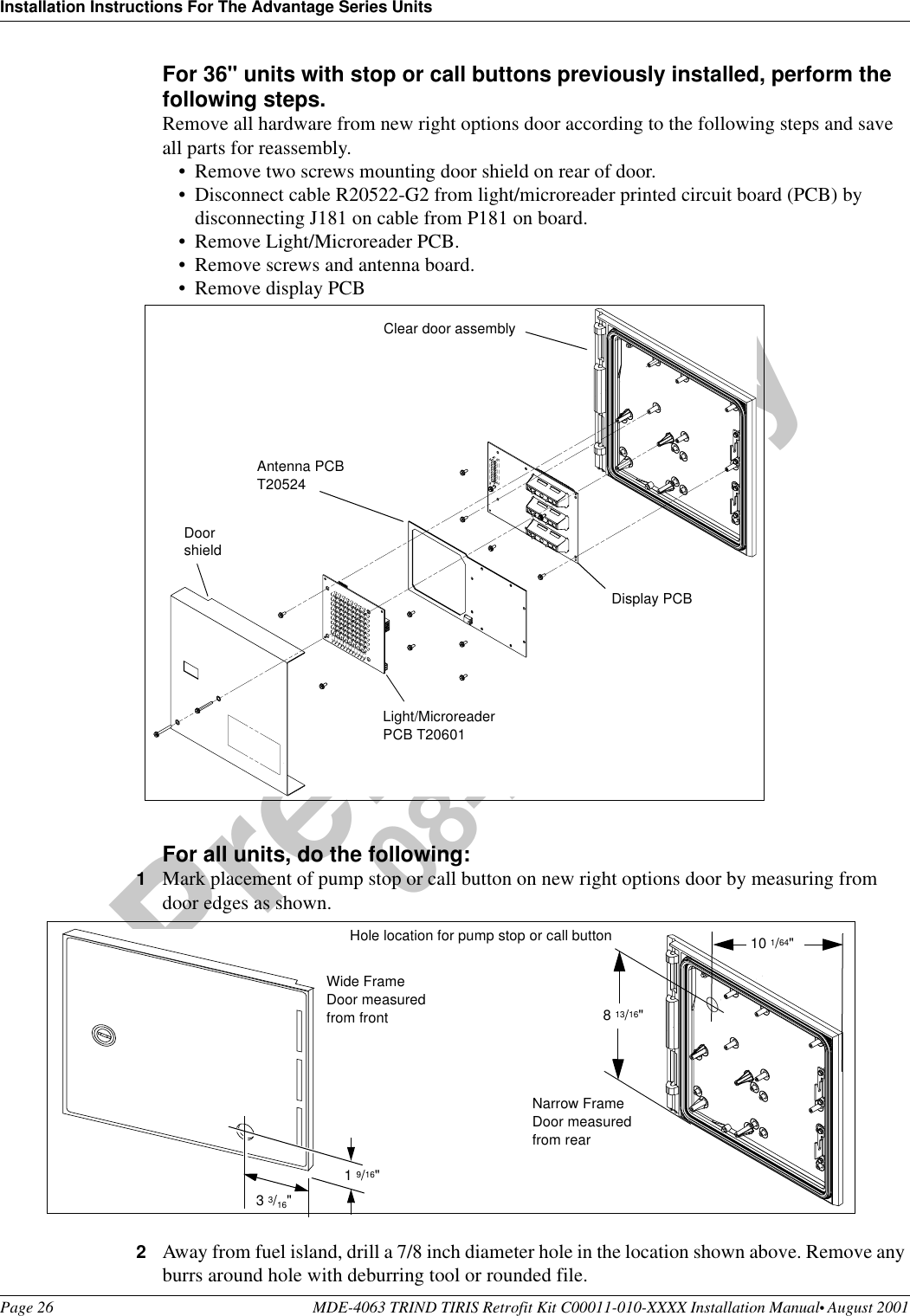
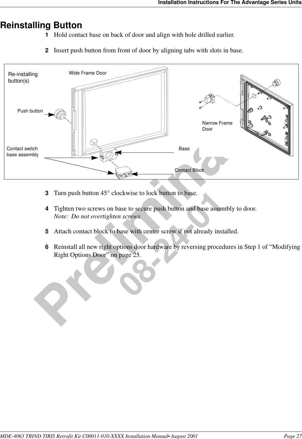
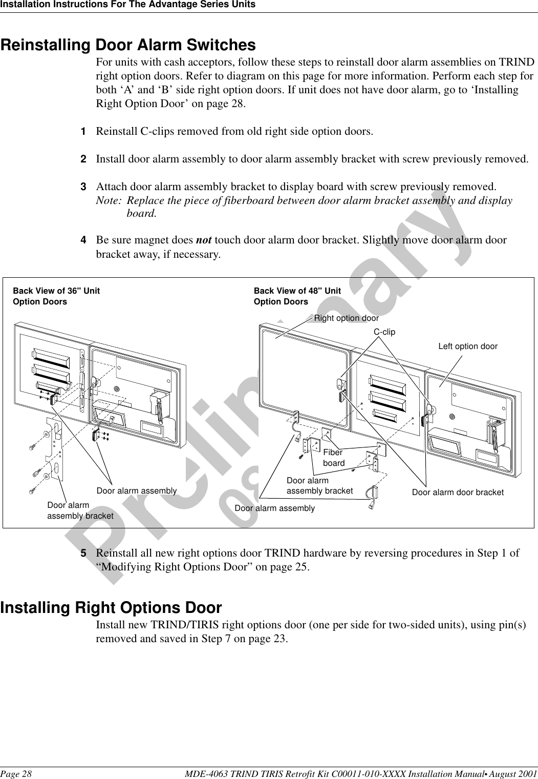
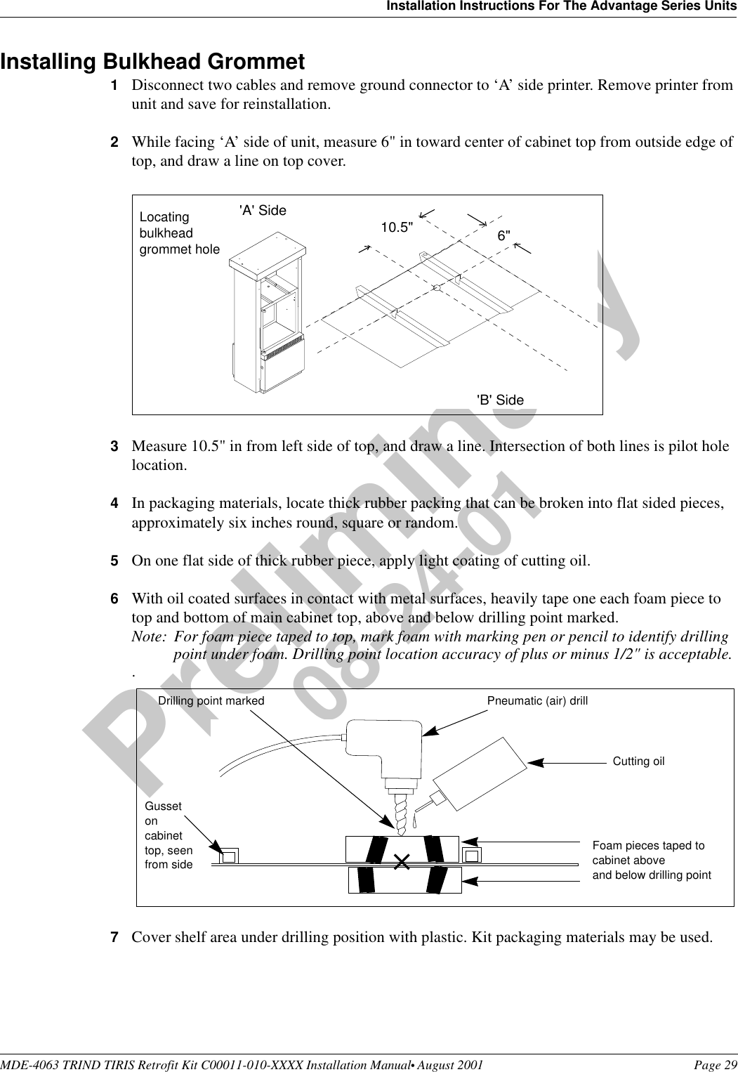
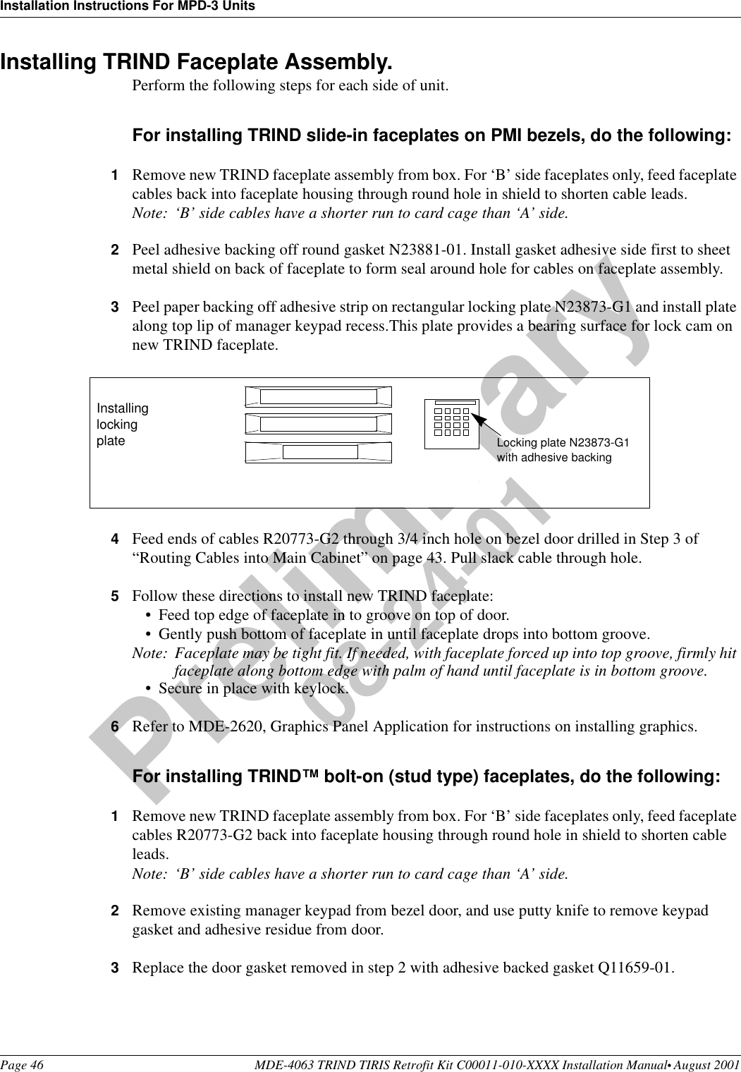
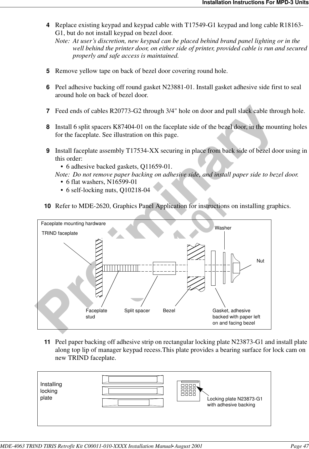
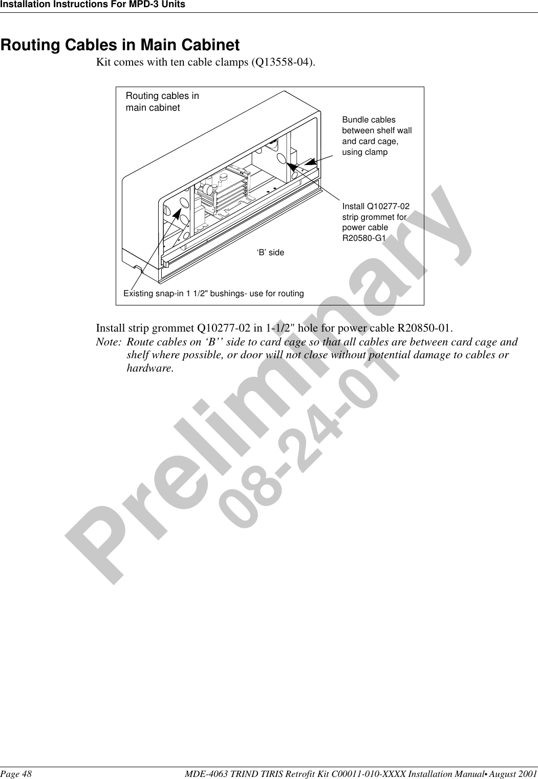
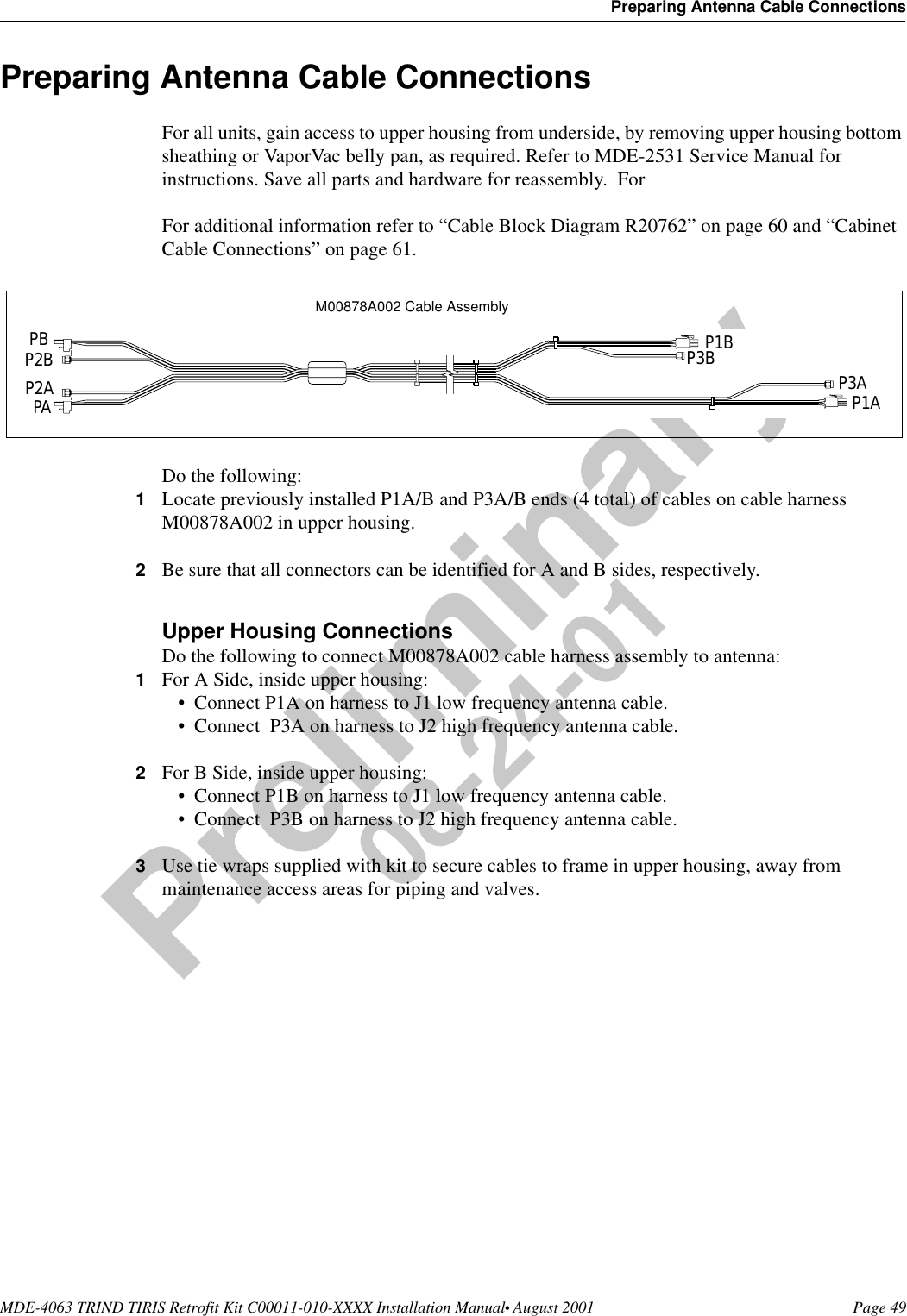
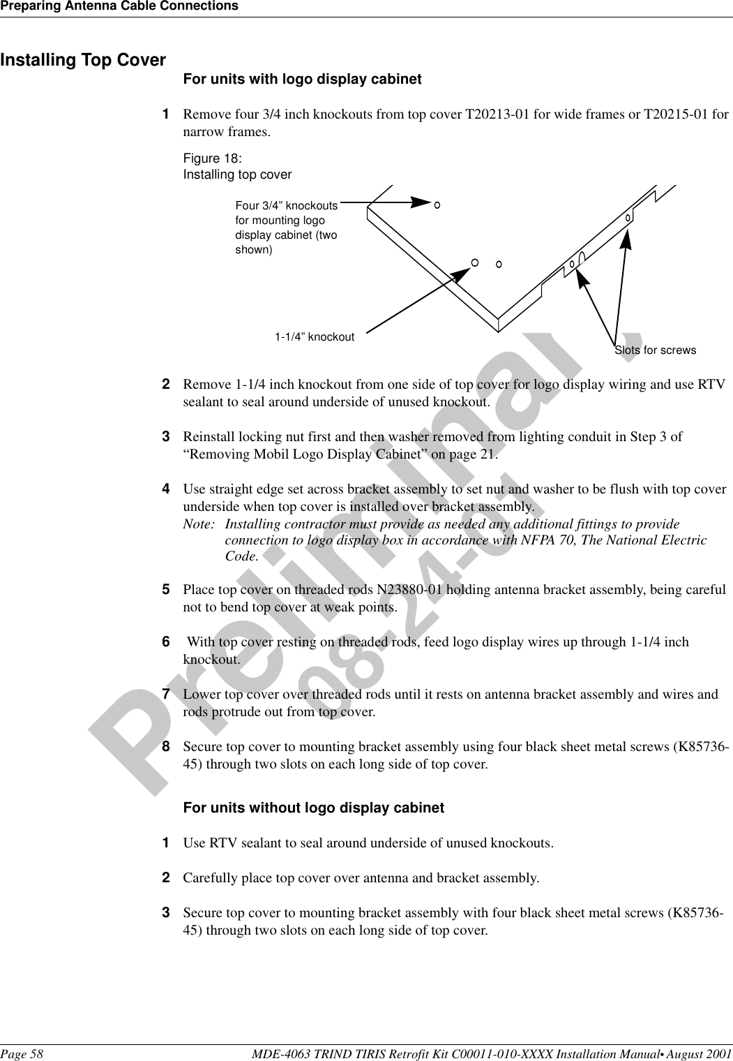
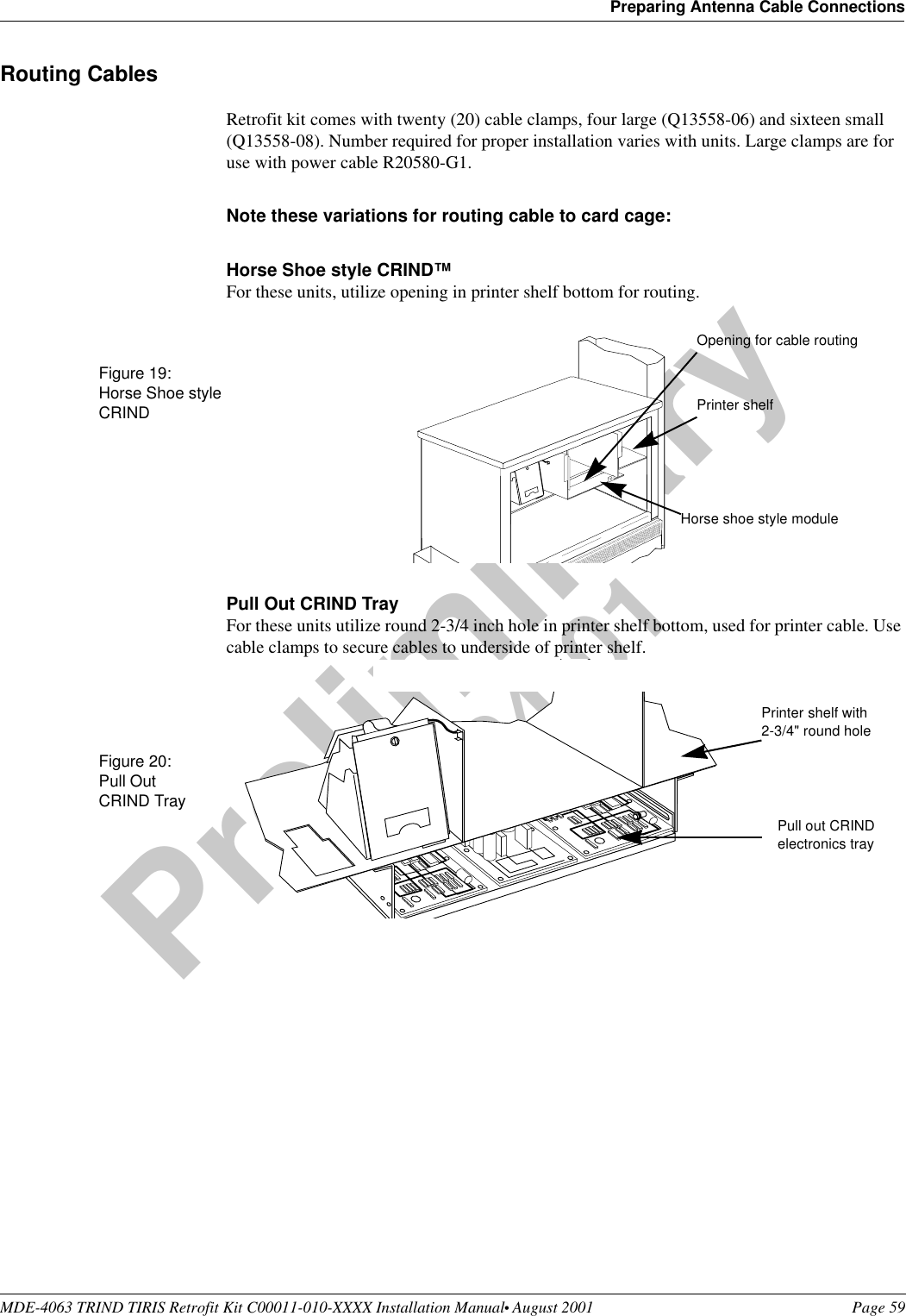
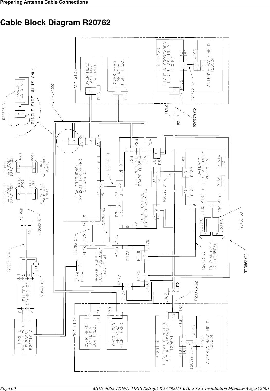
Gilbarco MRIR10 Hand Held Tag Reader User Manual
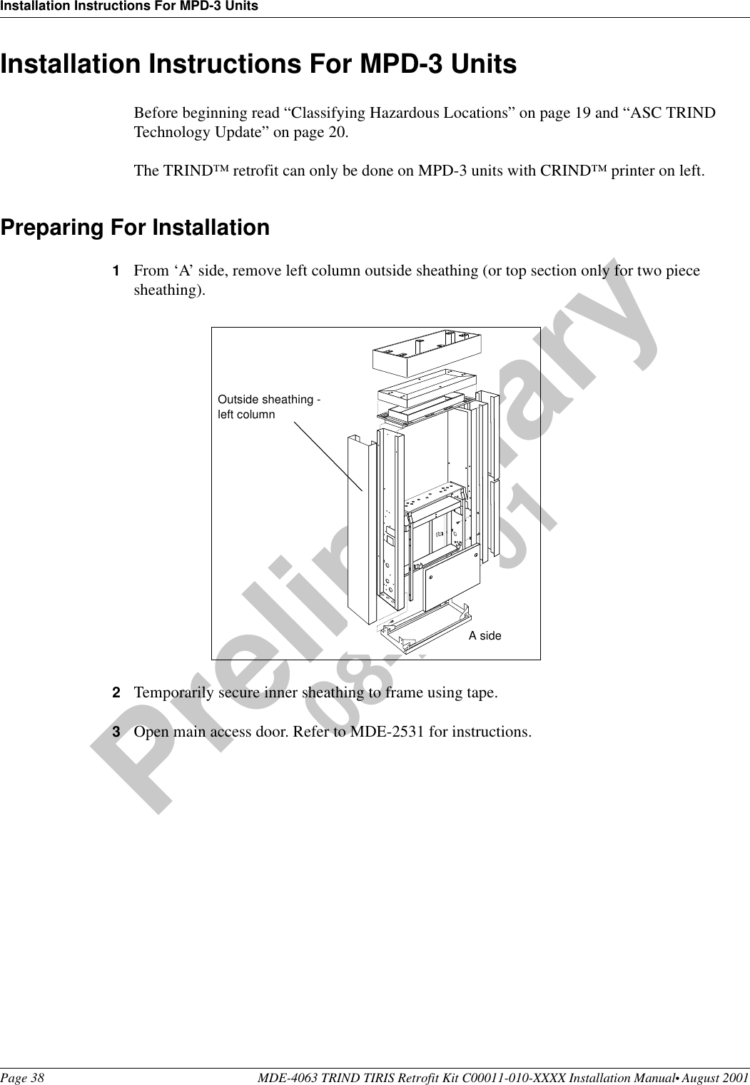
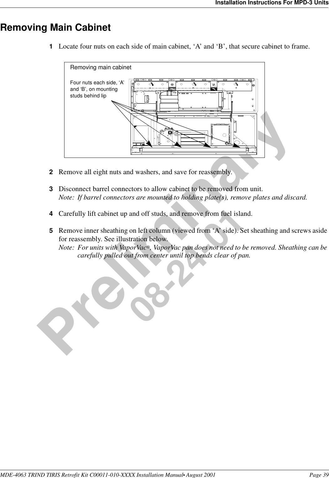
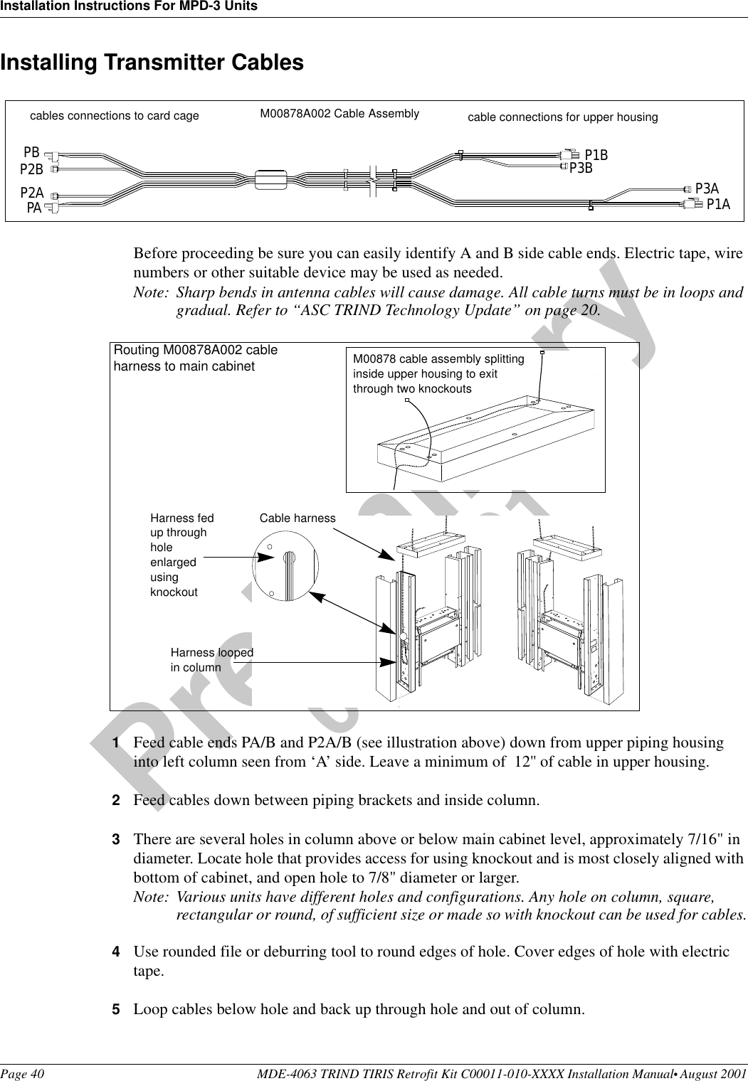
Gilbarco Inc. Hand Held Tag Reader
UserManual.wiki
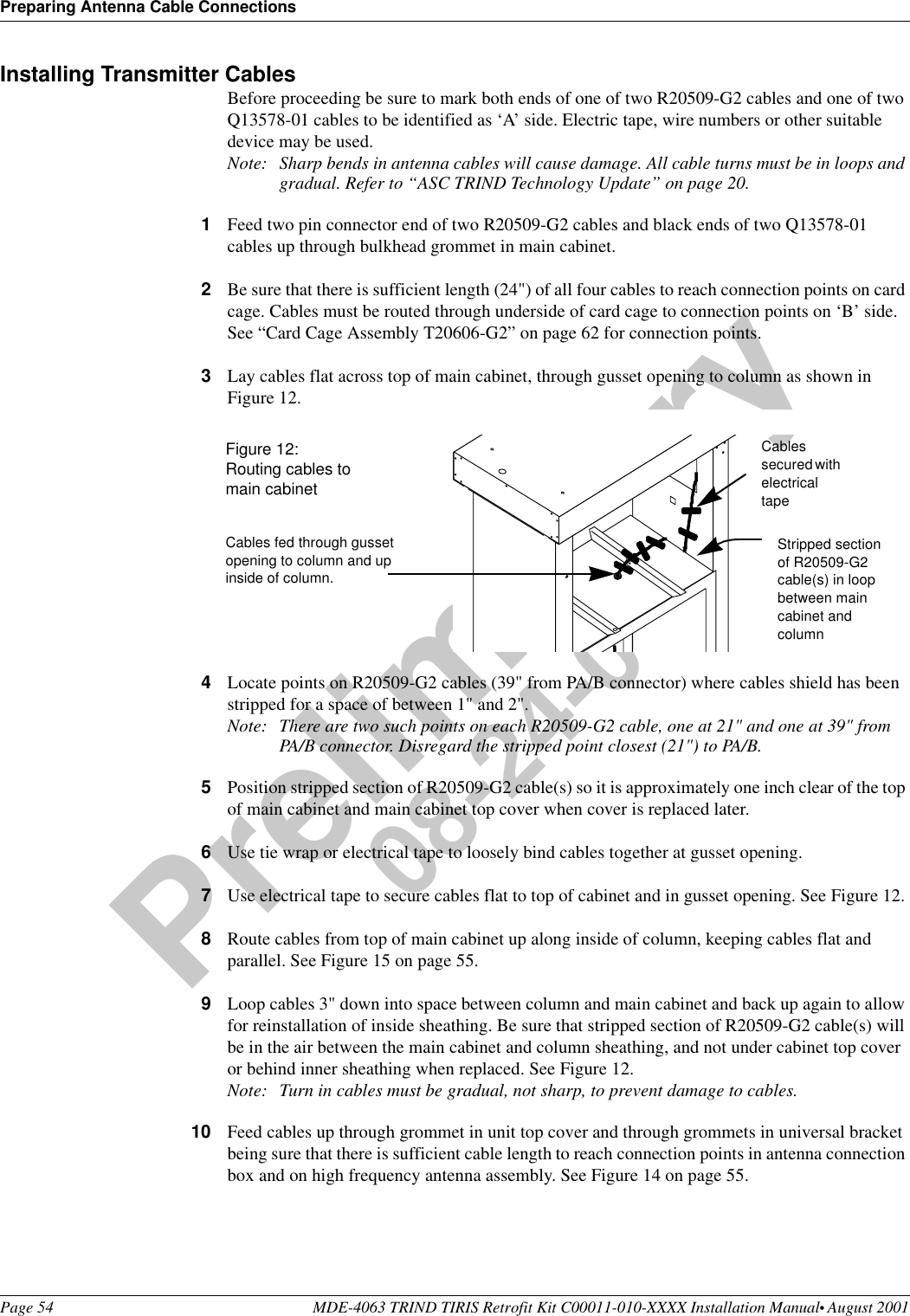
>
Gilbarco
>
MRIR10 User Manual
Manual
Navigation menu
Upload a User Manual
Namespaces
Wiki Guide
HTML
PDF
Info
Views
User Manual
Discussion / Help
Navigation