Harris Farinon Division 9GKAUR5802T1-1 AURORA 5800 Spread Spectrum Microwave Radio System User Manual
Harris Corporation Farinon Division AURORA 5800 Spread Spectrum Microwave Radio System
UserManual.wiki
>
Harris Farinon Division
>
9GKAUR5802T1 1 User Manual
Users Manual
Navigation menu
Upload a User Manual
Namespaces
Wiki Guide
HTML
PDF
Info
Views
User Manual
Discussion / Help
Navigation
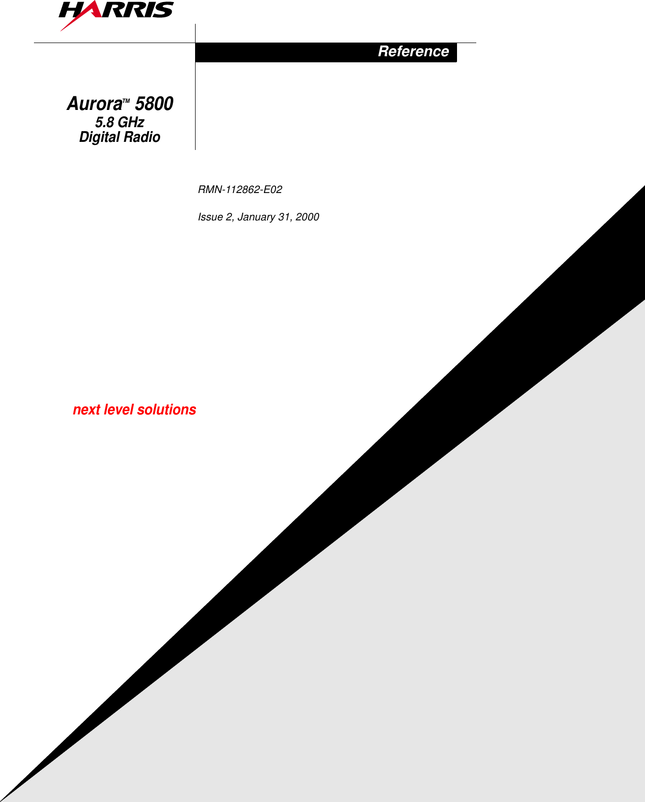

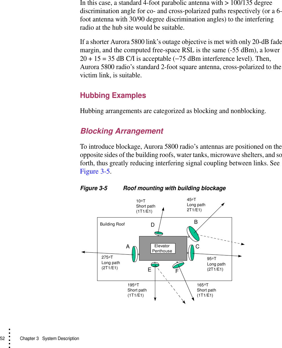
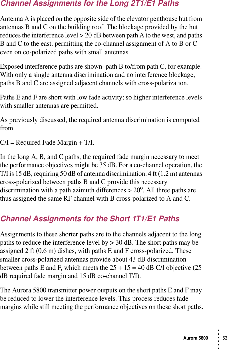

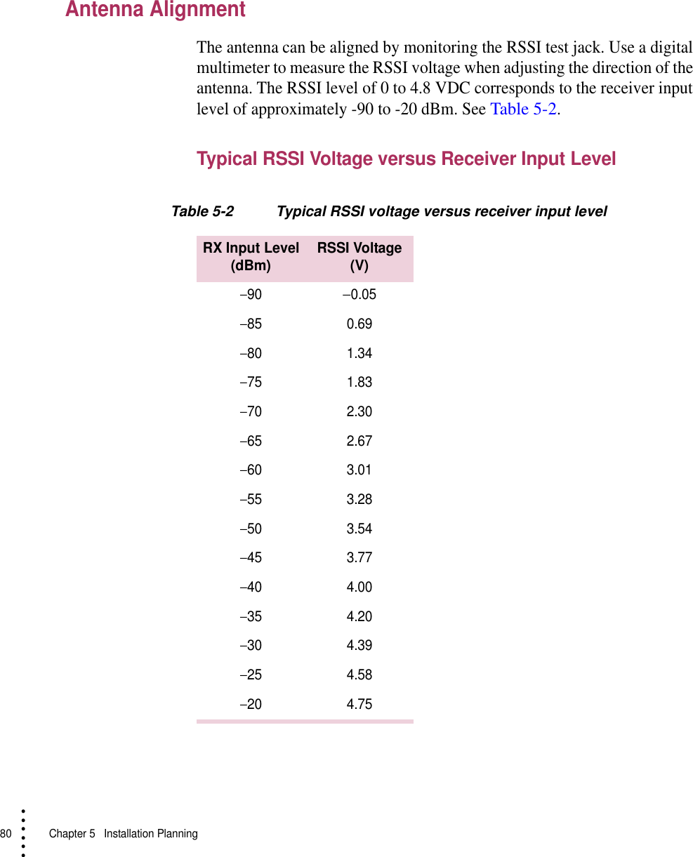
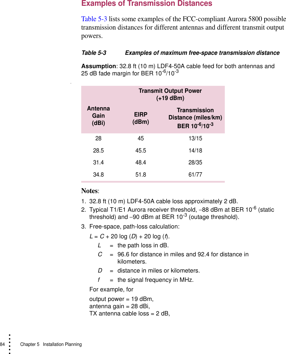
![72 Chapter 5 Installation Planning• • • •••However, good engineering judgment should be exercised by the operator and professional installer before selecting paths or locations near equipment or facilities that could generate interfering signals. Such equipment might include high-power ISM devices. Additionally, precaution should be taken when links are deployed in a region where a large number of other 5.8-GHz, point-to-point or point-to-multipoint links are installed. In some interference cases, threshold degradation causing an increase in short-term multipath outage or a slightly degraded Residual Bit Error Ratio (RBER) may occur, either or both of which can probably be tolerated.As a general rule, the deployment of a larger antenna with a smaller beam width and higher front-to-back ratio, an antenna relocation for better interference shielding, or a polarization change are often very effective in mitigating most interference cases. These subjects are discussed in a later section. Such field changes, to mitigate interference and to otherwise improve Aurora 5800 link performance, require no prior regulatory approval in unlicensed links.Performance and Economic ConsiderationsAurora 5800 microwave transport offers significant technical and economic advantages over conventional copper- or fiber-based leased or owned transport alternatives when availability, cost-effectiveness, implementation time, security, and difficult terrain or access are significant network design considerations.Ref. [1] describes how the economic and technical challenges of creating a new telecommunications infrastructure are met more effectively with point-to-point radio links than with traditional wireline-based solutions.When Aurora 5800 digital transport facilities are compared to conventional leased-line services, the following four factors are taken into consideration:•Transmission quality and reliability•Circuit availability•Short-haul costs•Construction time](https://usermanual.wiki/Harris-Farinon-Division/9GKAUR5802T1-1/User-Guide-89804-Page-74.png)
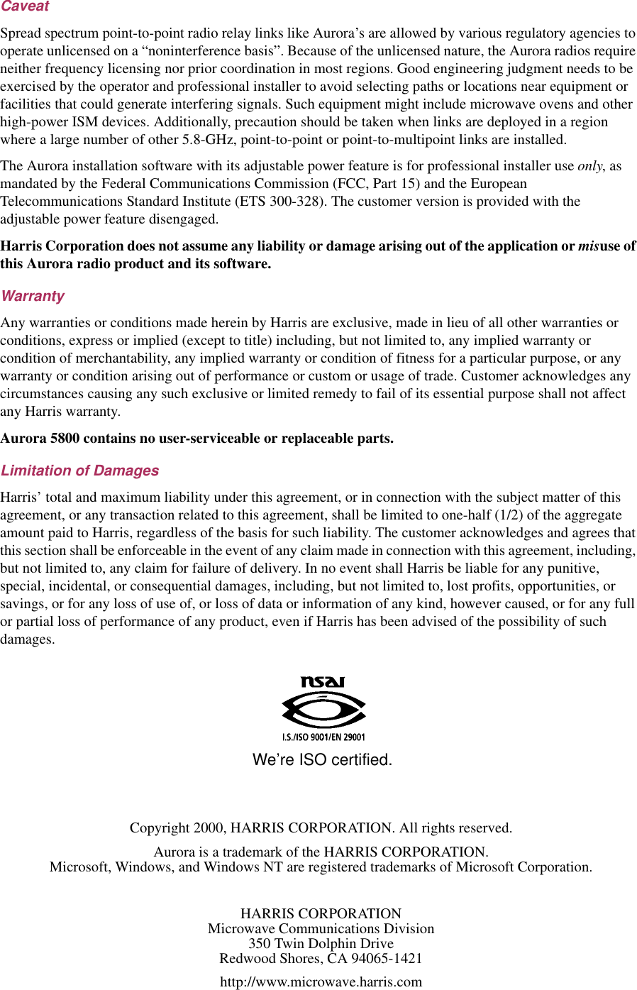
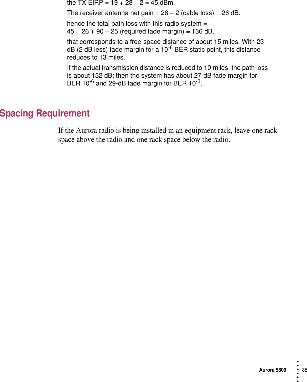
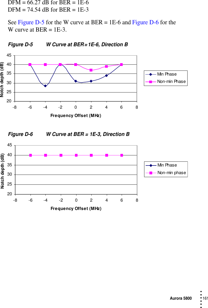
![76 Chapter 5 Installation Planning• • • •••antenna. The FCC has a new rule on how much antenna gain affects the input power to the antenna and the output power of a radio operating in the 2400-MHz ISM band, but this rule does not apply to the 5.8-GHz links.PolarizationAll 5.8-GHz antennas offer a choice of linear polarization. Aurora 5800 radios usually operate with antennas that are polarized either vertically or horizontally, as long as the polarization is the same at both ends of the path. Cross-polarization greatly reduces signal strength.Site SelectionLink PerformanceAurora 5800 radio’s link performance can be characterized not unlike that of any conventional 6-GHz, point-to-point, nondiversity microwave link. Ref. [2] lists various availability and outage models and objectives from which to select.While the “short-haul” objective (about 27 min/yr or 9 min/any month, end-to-end, one-way T1/E1 trunk outage) may be suitable for most applications, many Aurora 5800 radios are often used for temporary links or as an alternative to copper wire services. A higher outage objective may therefore be assigned to a DSSS link, resulting in significant savings in the cost of antennas and support structures.Aurora 5800 radio’s wide, robust transmitted spectra reduce the probability of multipath fade outage on these links. In sharp contrast to FM analog radio links where the RF carrier disappears, or a broadband Quadrature Phase-Shift Keying (QPSK) or other digital links where increased multipath outage occurs with signal distortion (dispersion), spread-spectrum signals are not nearly as affected by multipath notches.Aurora 5800 radio’s Dispersive Fade Margins (DFMs), the measure of its sensitivity to path-generated spectrum distortion, exceed 60 dB and are thus disregarded in performance calculations.](https://usermanual.wiki/Harris-Farinon-Division/9GKAUR5802T1-1/User-Guide-89804-Page-78.png)
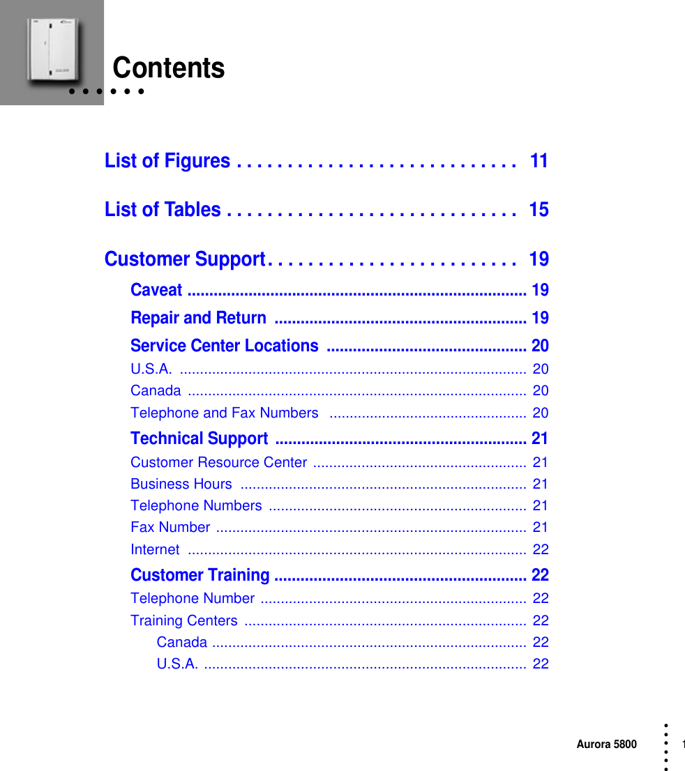
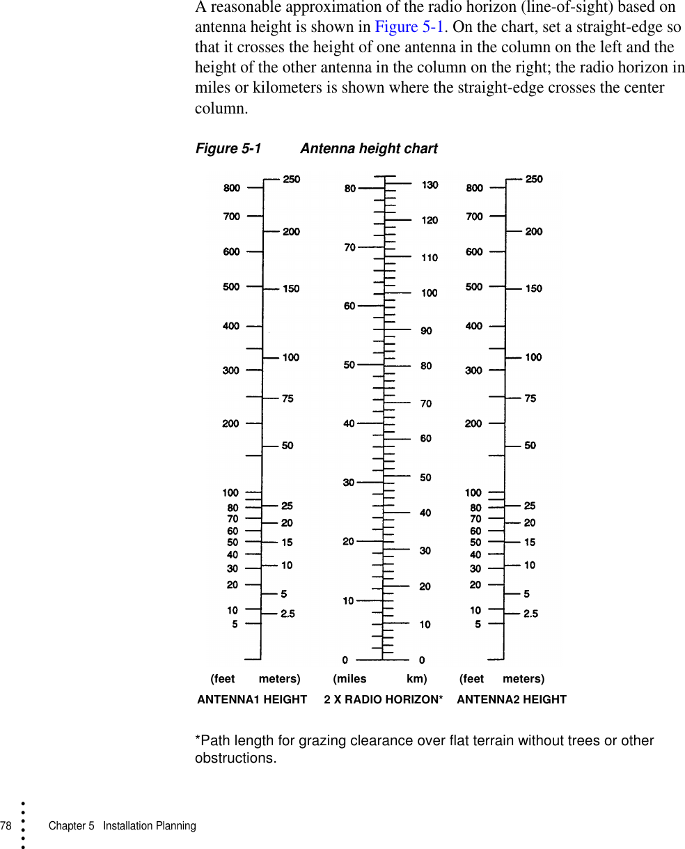
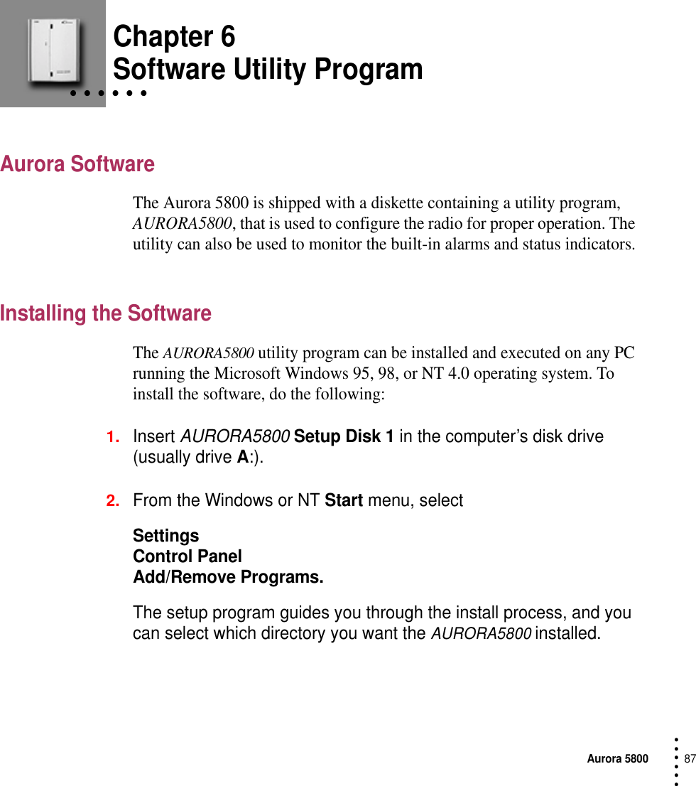
![Aurora 580077 • • • •••For this reason, the addition of diversity protection to lower multipath fade outage is rarely necessary to meet performance objectives. If equipment protection is needed, then dual Aurora 5800 radios on cross-polarized or separate antennas with T1 or E1 span line switches are suggested. Vertically separated antennas (paths) provide a reduction in multipath outage, although T1/E1 span line switching is not hitless.Path Clearance and ReliabilityAs a general rule, spread-spectrum links can be assigned about the same 0.6 F1 at k = 11 path clearance as standard (licensed point-to-point analog and digital radio-relay links) in the 6-GHz band.Since many Aurora 5800 links are short and nondiversity, low clearance paths over reflective terrain (such as open fields or lakes) are usually more stable (fade-free) than those with excessive path clearance. Tables of link reliability under different conditions of terrain, climate, antenna size, and path distance are available from Harris [Ref. 3]. The received signal level and path reliability (outage or SESR) results under a wide variation of link design conditions can be determined by using Harris MCD’s StarLink shareware personal path engineering computer program, which is available at no cost. [Ref. 4]Antenna Site SelectionA good antenna site has the following qualifications:•A clear line of sight for optimum power and maximum range•Sufficient elevation for maximum line-of-sight range•Correct orientation and correct directional aim at the target antenna•Shortest possible distance between antenna and radio unit1. “k” is the ratio of the radius of curvature (refractivity) of the radio path to that of the earth. A k = 1 (no refractive ray bending over a true earth) is commonly used for longer paths.](https://usermanual.wiki/Harris-Farinon-Division/9GKAUR5802T1-1/User-Guide-89804-Page-79.png)


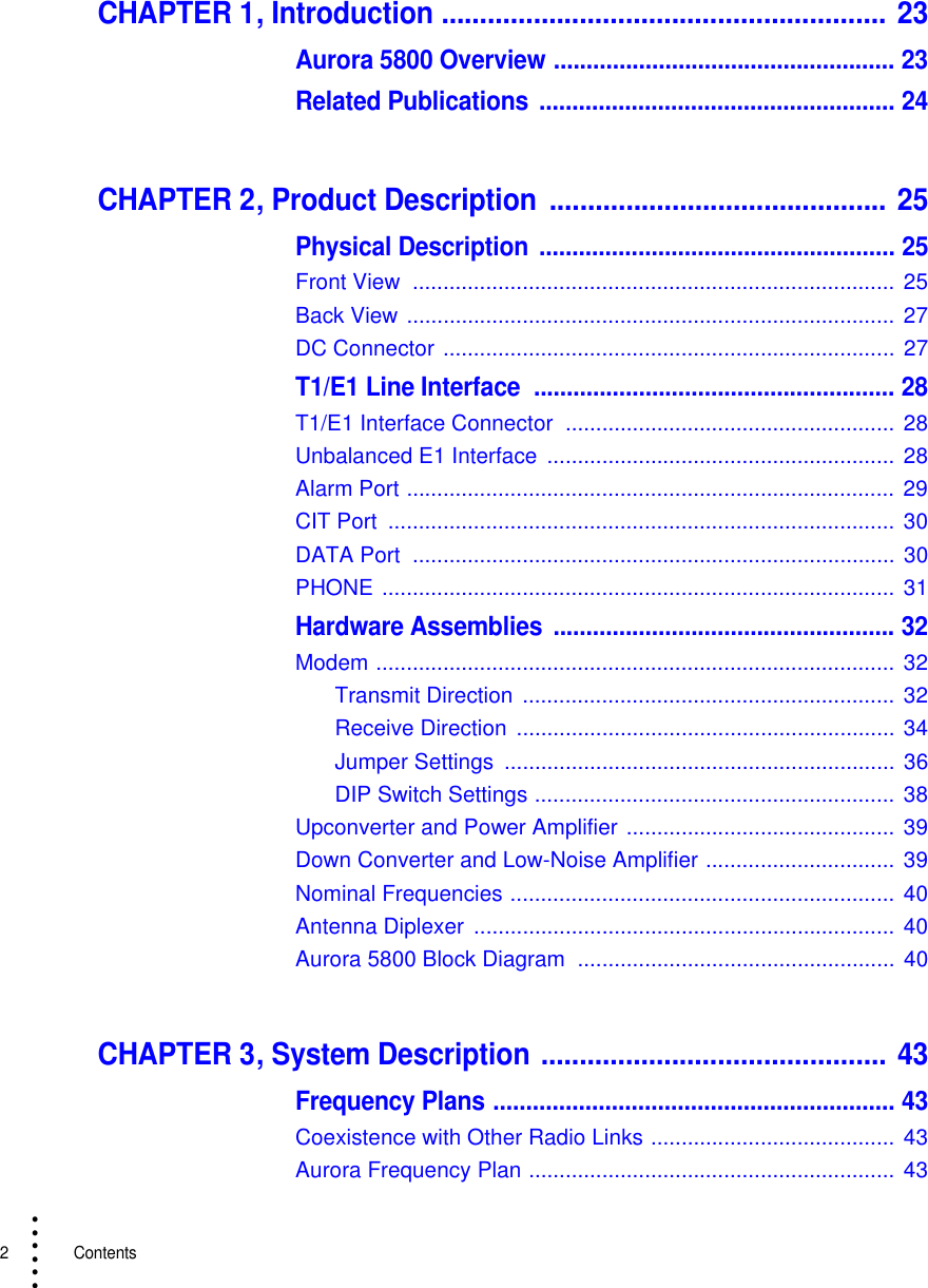
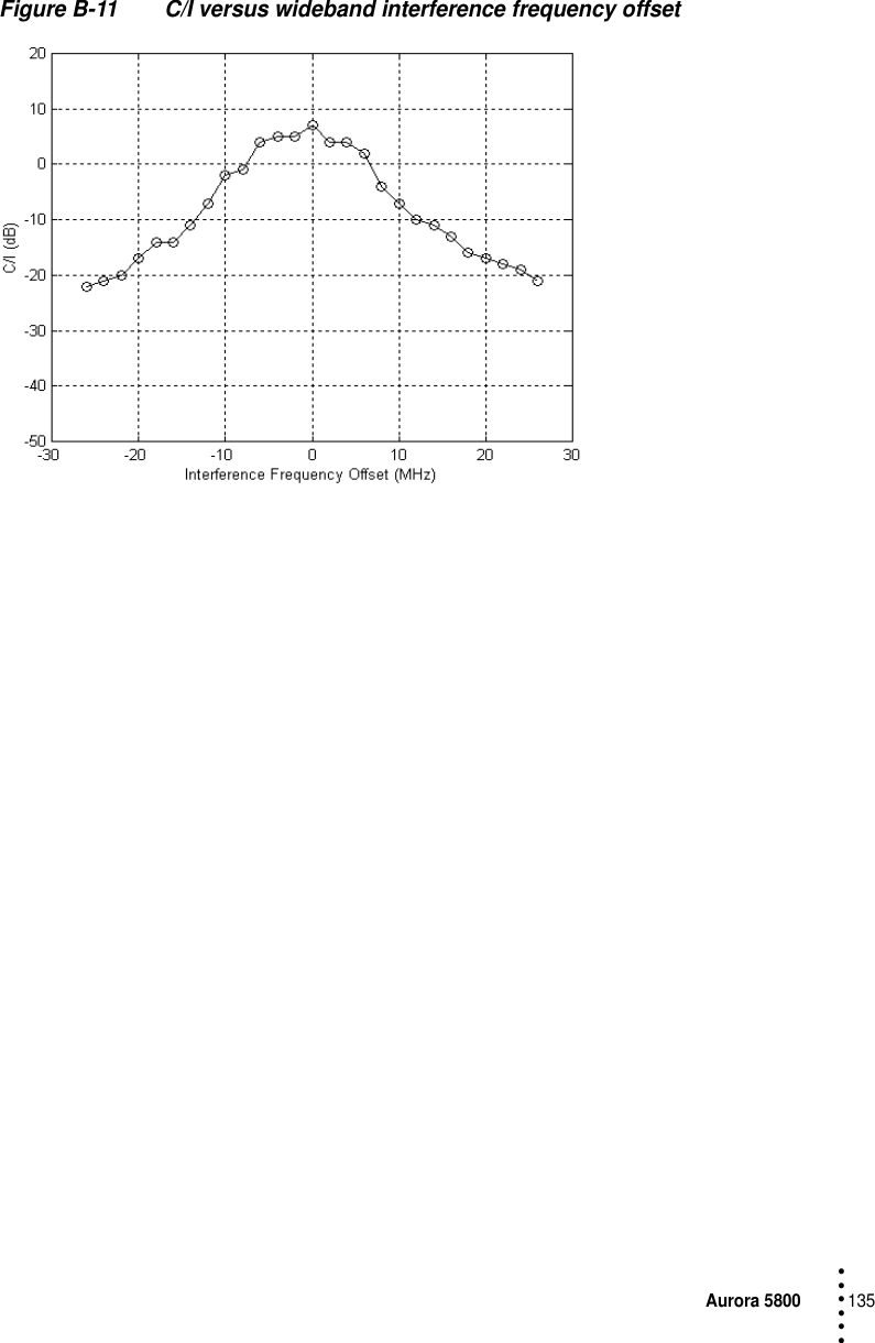
![132 Appendix B Typical Radio Performance Results for T1• • • •••Flat FadingSweep for ultimate error-free attenuation range (flat fading), elapse time: 0.1 sec.Note: Attenuation is inserted in the IF path. RF AGC is disabled. Only the dynamic performance of the IF AGC is tested.Direction A: 0 to 55 dBDirection B: 0 to 55 dBInterference PerformanceThe effect of an interfering signal into a digital radio receiver is characterized by a 1 dB degradation in the BER = 1 × 10 -6 (static) and 1 × 10 -3 (outage) thresholds. The standard for this characteristic is the threshold-to-interference (T/I) ratio, as defined in EIA/TIA Document TSB-10-F. [Ref 5]The test was performed for sinewave (narrowband) interference and for like signal (wideband) interference. The method used in this test follows the TIA Bulletin TSB-10-F Standard T/I measurement recommendation.The C/I uses nominal receiver input level (− 40 dBm), and then interference is injected to get a BER of 10-6. C/I is the ratio of the signal to interference ratio at this point, measured in direction A only.](https://usermanual.wiki/Harris-Farinon-Division/9GKAUR5802T1-1/User-Guide-89804-Page-134.png)
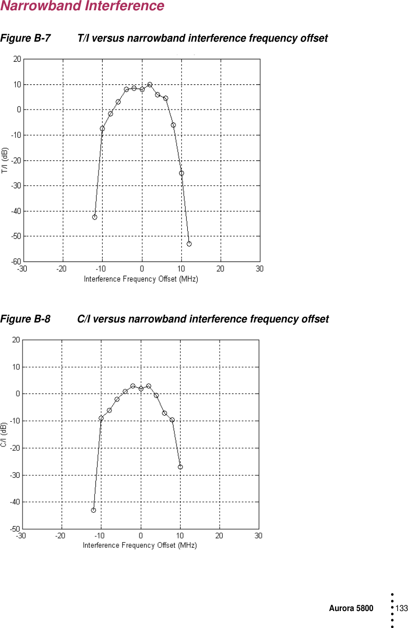
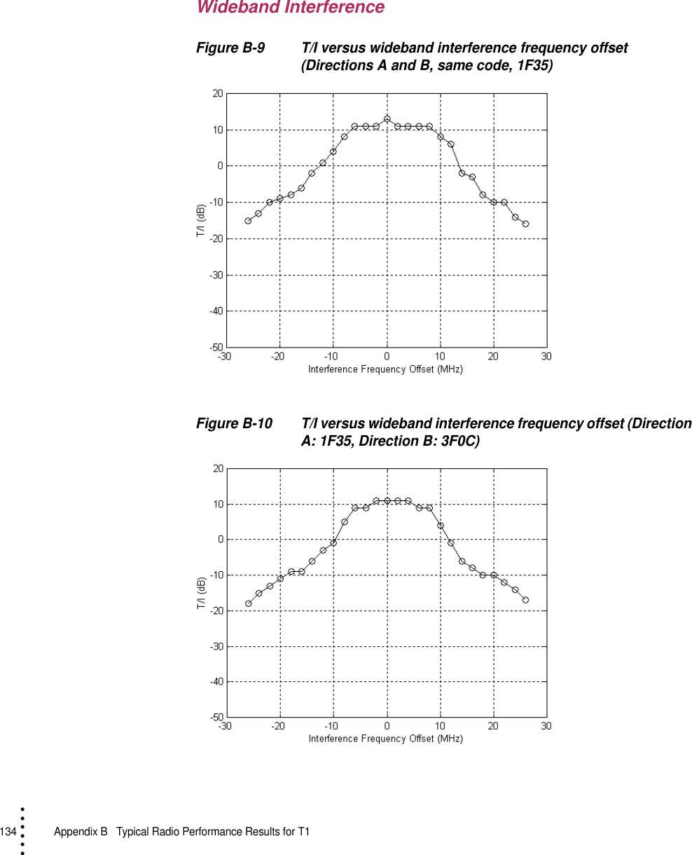

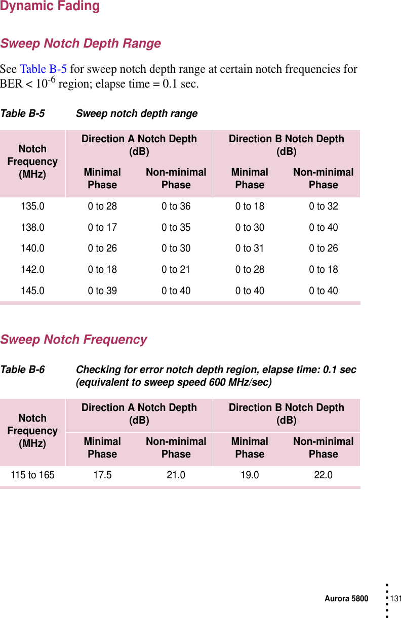
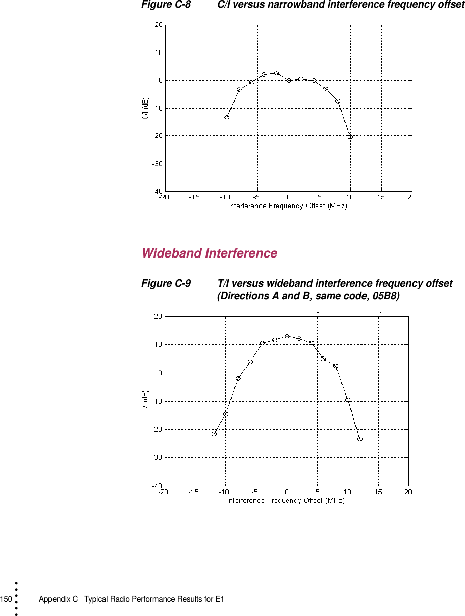
![Aurora 5800149 • • • •••Interference PerformanceThe effect of an interfering signal into a digital radio receiver is characterized by a 1 dB degradation in the BER = 1 × 10 -6 (static) and 1 × 10 -3 (outage) thresholds. The standard for this characteristic is the threshold-to-interference (T/I) ratio, as defined in EIA/TIA Document TSB-10-F. [5]The test was performed for sinewave (narrowband) interference and for like signal (wideband) interference. The method used in this test follows the TIA Bulletin TSB-10-F Standard T/I measurement recommendation.The C/I uses nominal receiver input level (− 40 dBm), and then interference is injected to get a BER of 10-6. C/I is the ratio of the signal to interference ratio at this point, measured in direction A only.Narrowband InterferenceFigure C-7 T/I versus narrowband interference frequency offset](https://usermanual.wiki/Harris-Farinon-Division/9GKAUR5802T1-1/User-Guide-89804-Page-151.png)
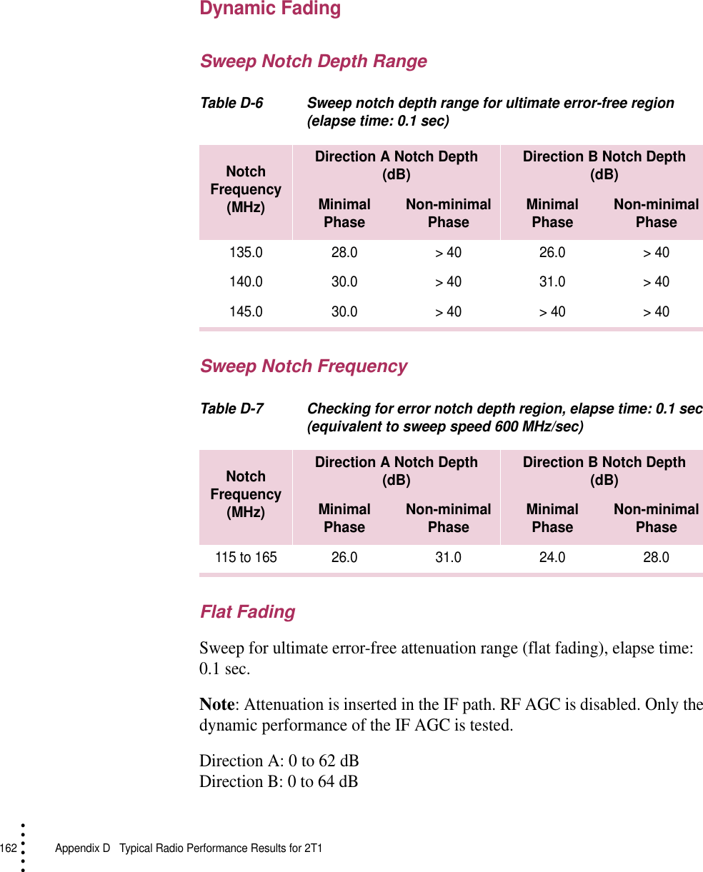
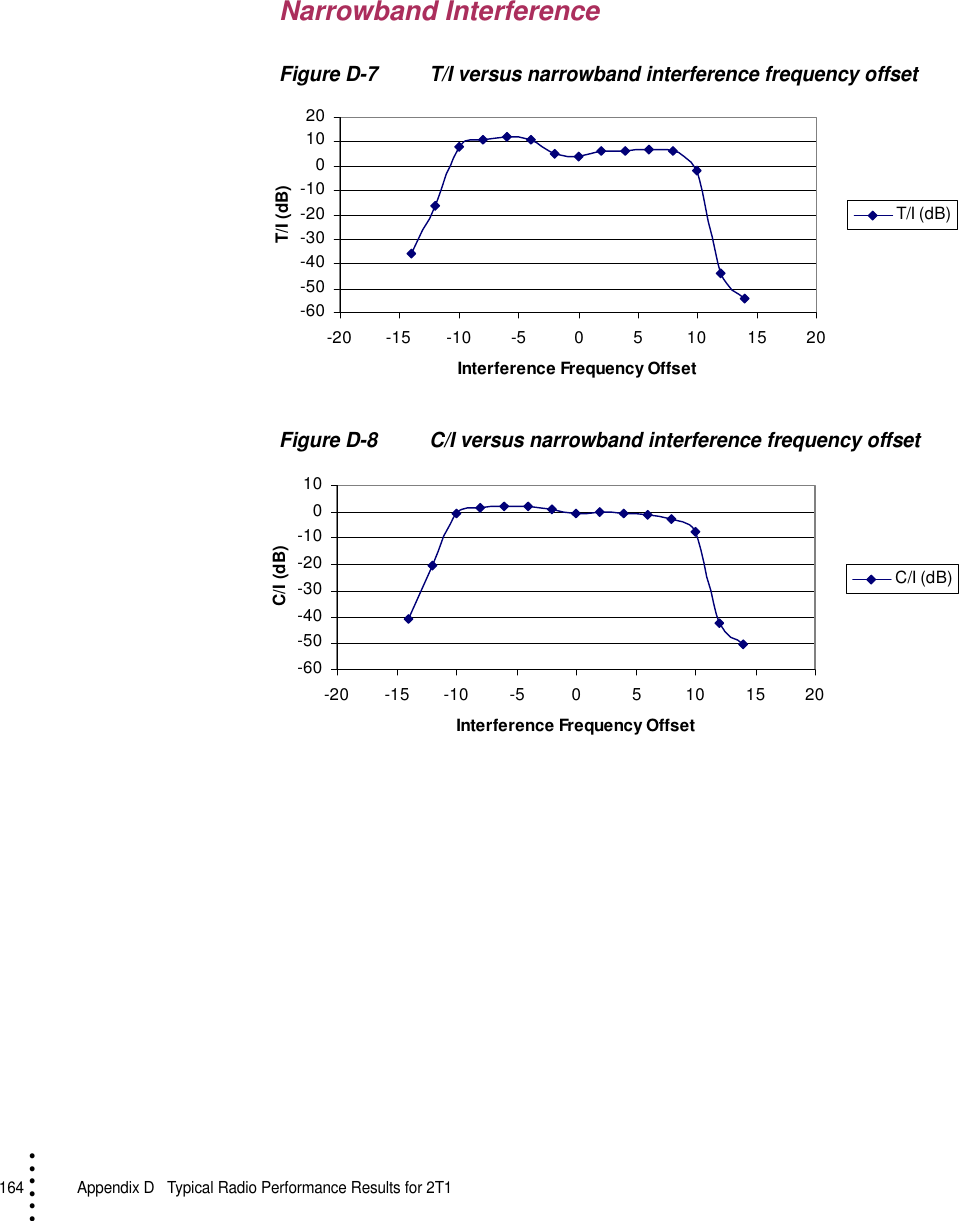
![Aurora 5800163 • • • •••Interference PerformanceThe effect of an interfering signal into a digital radio receiver is characterized by a 1-dB degradation in the BER = 1 × 10⁻⁶ (static) and 1 × 10⁻³ (outage) thresholds. The standard for this characteristic is the threshold-to-interference (T/I) ratio, as defined in EIA/TIA Document TSB-10-F. [5]The test was performed for sinewave (narrowband) interference and for like signal (wideband) interference. The method used in this test follows the TIA Bulletin TSB-10-F Standard T/I measurement recommendation.The C/I uses nominal receiver input level (− 40 dBm), and then interference is injected to get a BER of 10-6. C/I is the ratio of the signal to interference ratio at this point, measured in direction A only.](https://usermanual.wiki/Harris-Farinon-Division/9GKAUR5802T1-1/User-Guide-89804-Page-165.png)

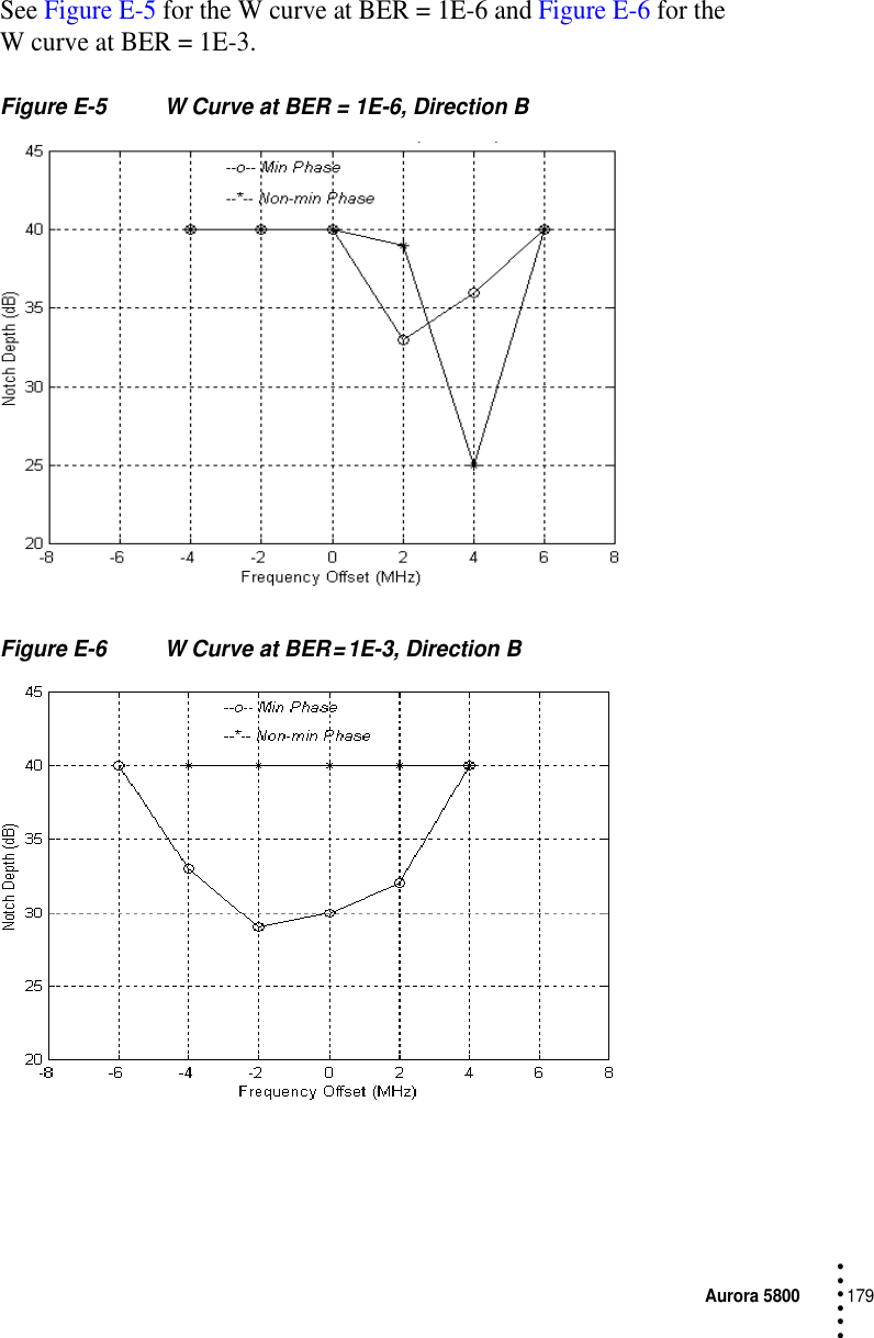
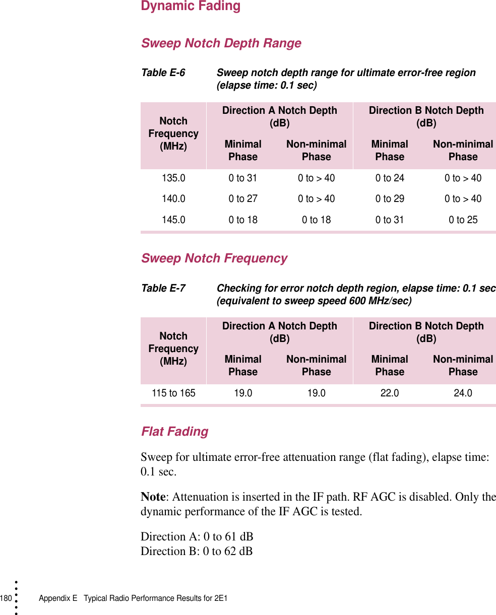
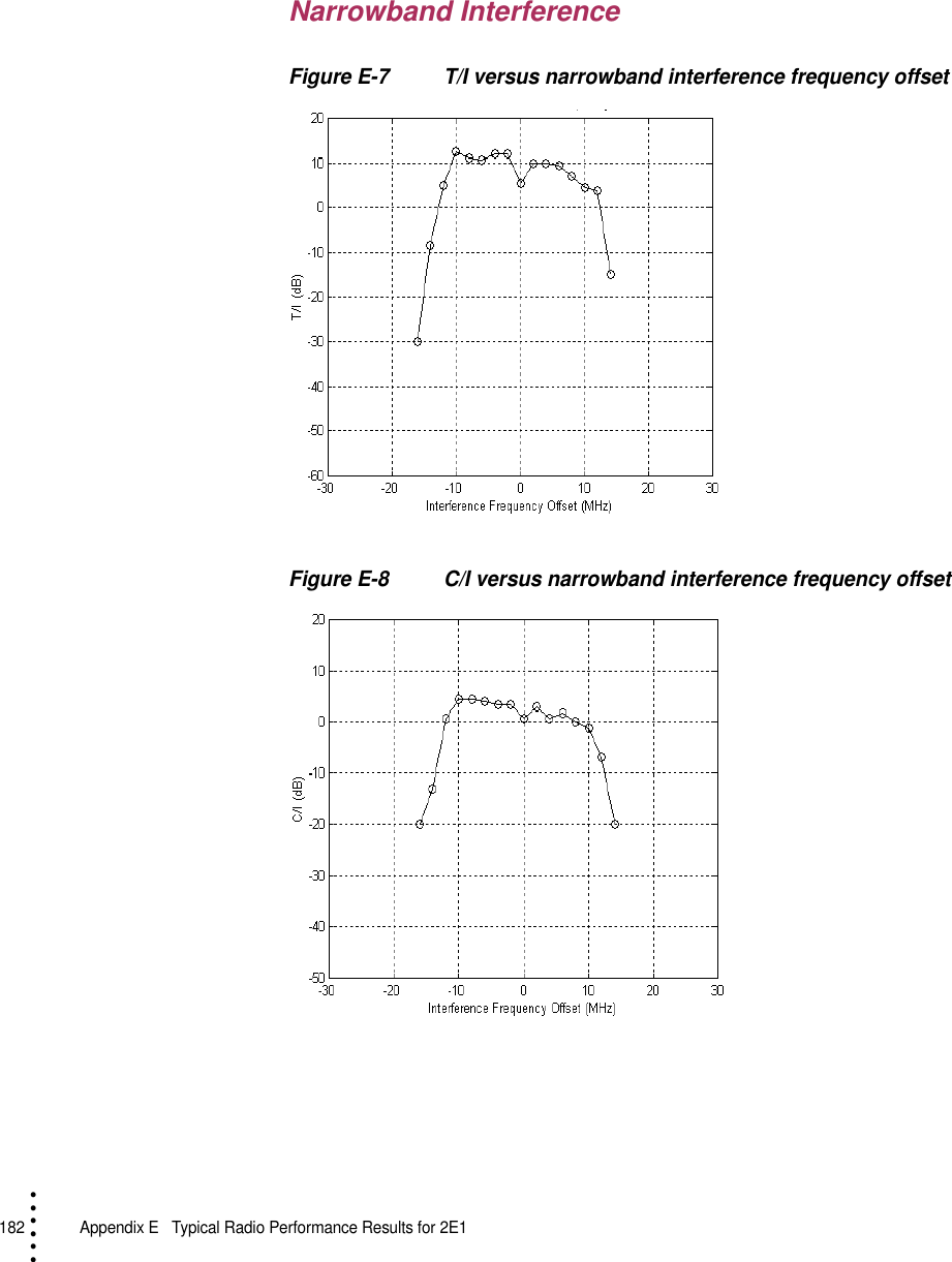
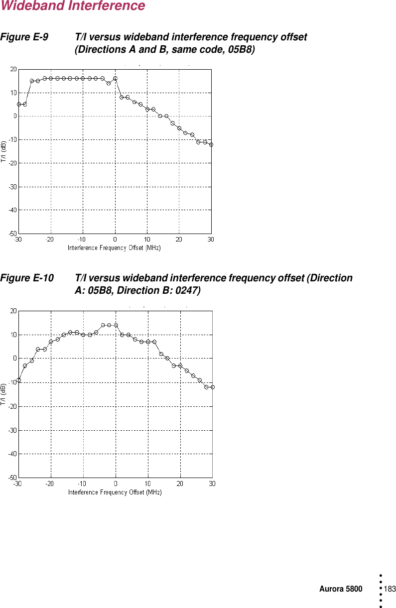
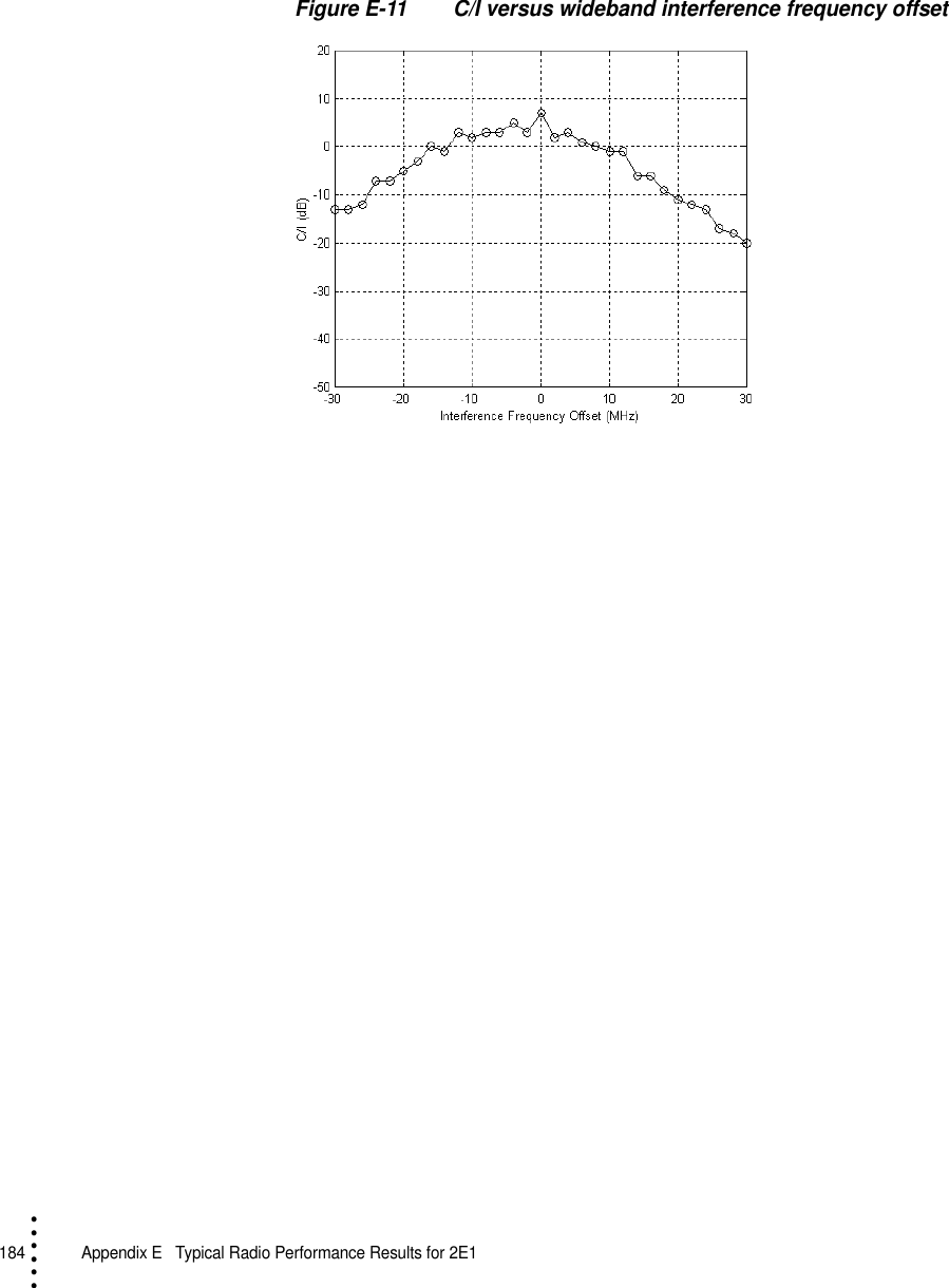
![Aurora 5800181 • • • •••Interference PerformanceThe effect of an interfering signal into a digital radio receiver is characterized by a 1-dB degradation in the BER = 1 × 10 -6 (static) and 1 × 10 -3 (outage) thresholds. The standard for this characteristic is the threshold-to-interference (T/I) ratio, as defined in EIA/TIA Document TSB-10-F. [Ref 5]The test was performed for sinewave (narrowband) interference and for like signal (wideband) interference. The method used in this test follows the TIA Bulletin TSB-10-F Standard T/I measurement recommendation.The C/I uses nominal receiver input level (− 40 dBm), and then interference is injected to get a BER of 10-6. C/I is the ratio of the signal to interference ratio at this point, measured in direction A only.See Figure E-7 to Figure E-11.](https://usermanual.wiki/Harris-Farinon-Division/9GKAUR5802T1-1/User-Guide-89804-Page-183.png)
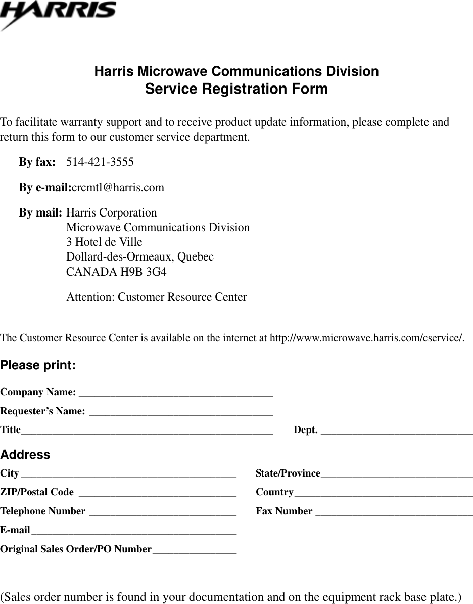
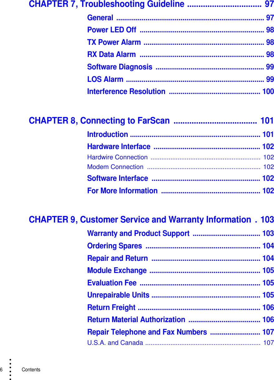
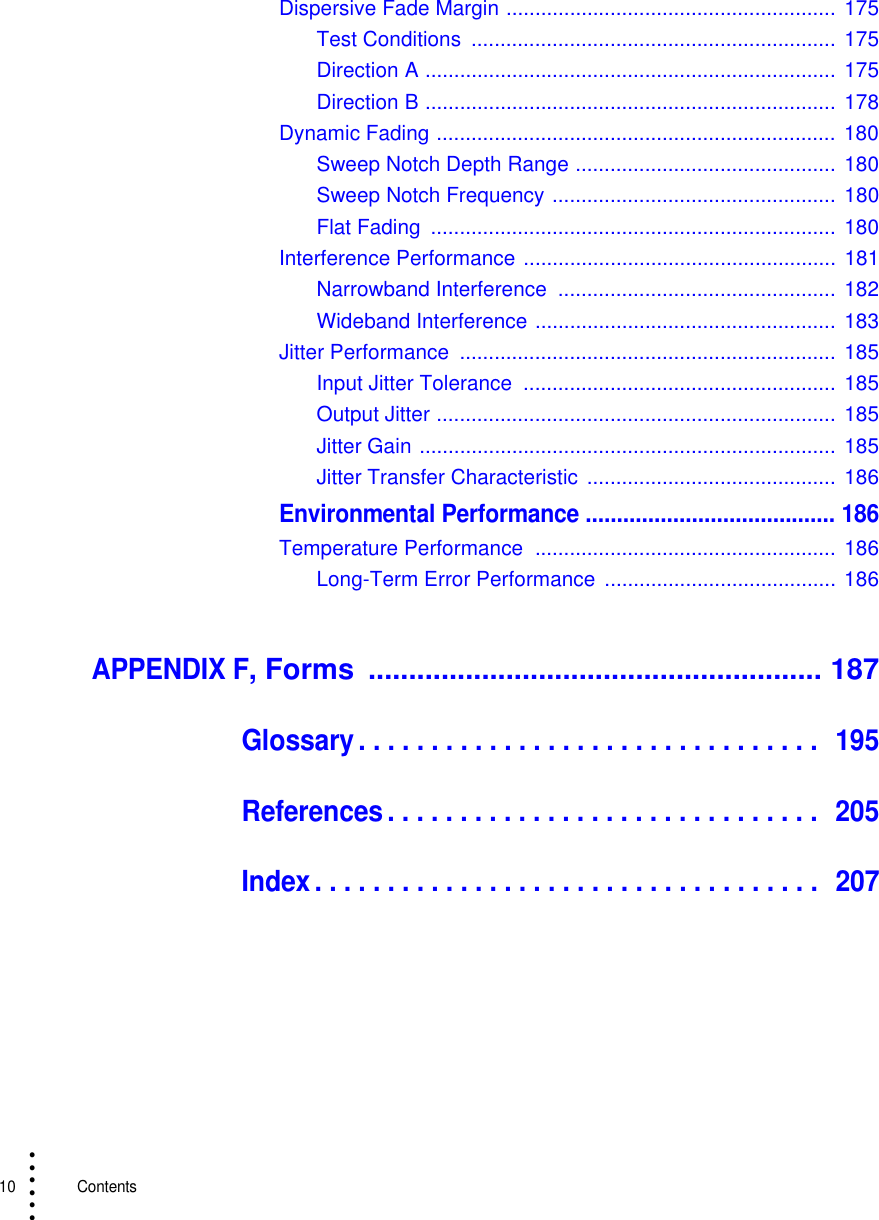
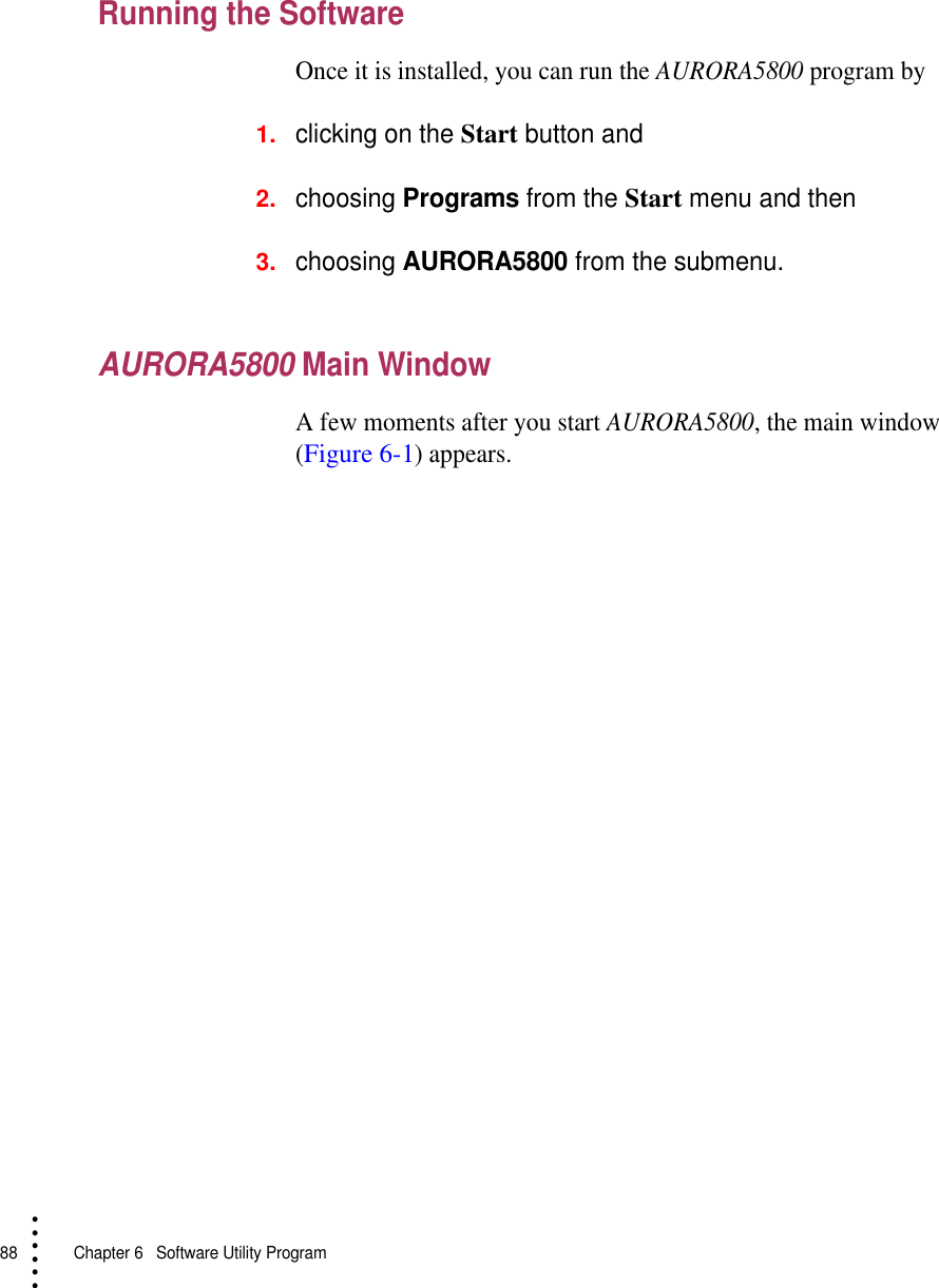
![Harris Microwave Communications DivisionRapid Request for Return Material Authorization (RMA)Service Locations:5727 Farinon Drive or 3, Hotel de Ville, Dollard-des-OrmeauxSan Antonio, TX 78249, USA Quebec, CANADA H9B 3G4Tel: 1-800-227-8332 or 1-800-465-4654, (+1) 514-421-8333Fax: (+1) 514-421-3555The Customer Resource Center is available on the internet at http://www.microwave.harris.com/cservice/.Company Name:_____________________________ Phone: ______________________________________Requester’s Name: __________________________ Fax:_________________________________________Billing Address Shipping Address____________________________________________ _________________________________________________________________________________________ _________________________________________________________________________________________ _____________________________________________Service Requested: [ ] Repair [ ] ExchangeRequested Repair Urgency: [ ] Standard [ ] ExpediteWarranty Status: [ ] IN-WARR (Provide Sales Order No.) _______________________________[ ] NON-WARR (Provide Purchase Order No.) _________________________Requested Mode of Shipment: [ ] Standard Service [ ] 2nd Day Air [ ] OvernightNOTE: IN-WARRANTY UNITS are returned via STANDARD SERVICE only. Please provide COURIER ACCOUNT NUMBER if faster delivery is required.________________________________________________________________SD Number and Options Part Description Problem/Service Required________________________ _____________________________ ________________________________________________________ _____________________________ ________________________________________________________ _____________________________ ________________________________________________________ _____________________________ ________________________________________________________ _____________________________ ________________________________Special Instructions_____________________________________________________________________________________________________________________________________________________________________________________________________________________________________________________________________________________________Please do not write below this spaceDate Form Received: ____________________ Rec by: _________________________ Your RMA # is: ________Repair/Exchange Price: Item 1_______________________ Item 4 _______________________Item 2_______________________ Item 5 _______________________Item 3_______________________ Item 6 _______________________](https://usermanual.wiki/Harris-Farinon-Division/9GKAUR5802T1-1/User-Guide-89804-Page-193.png)