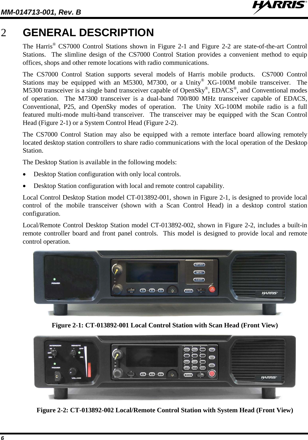
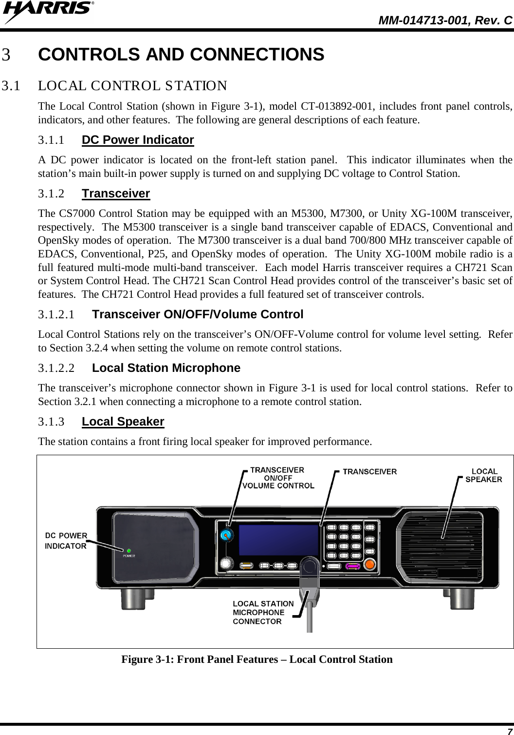
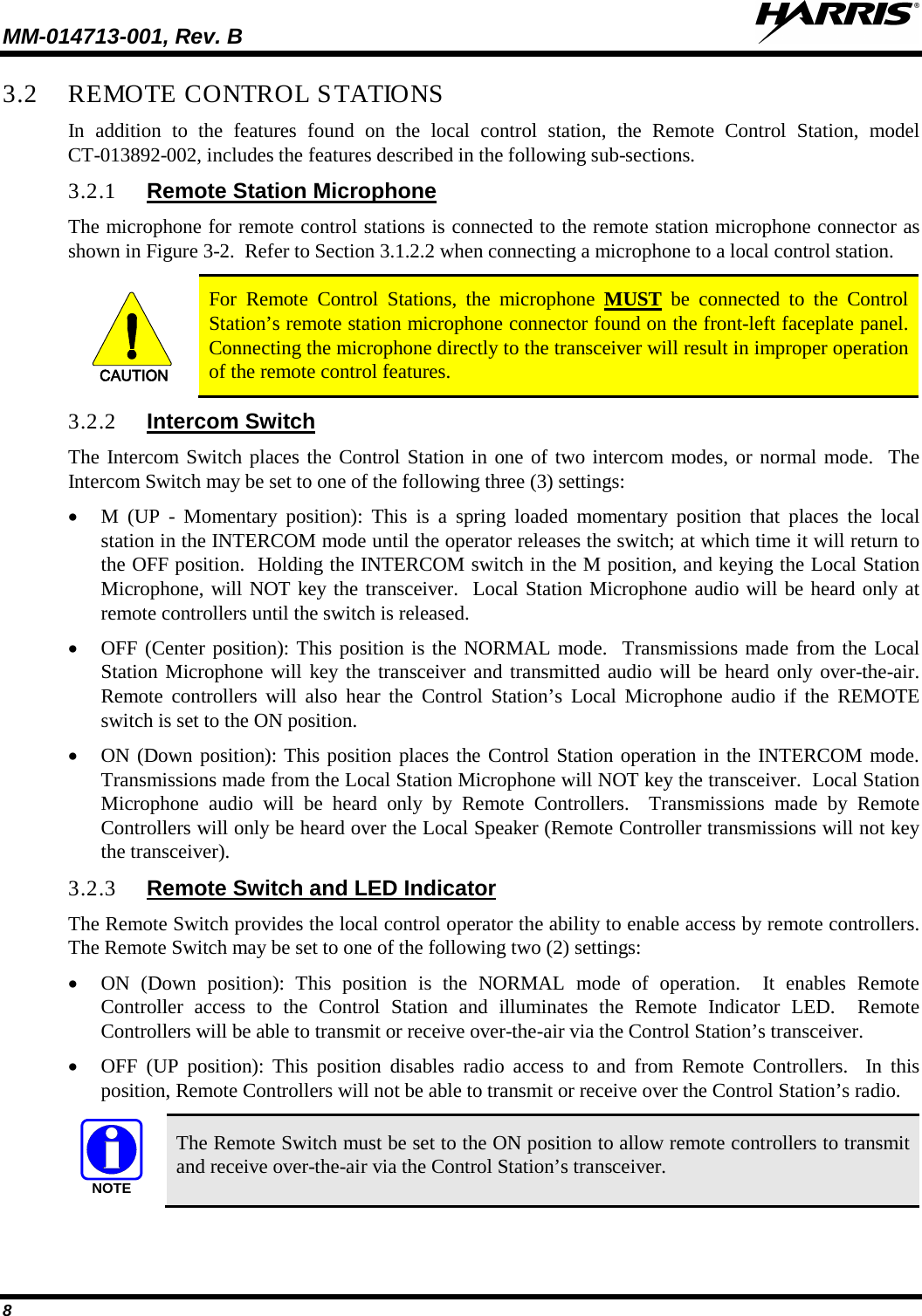
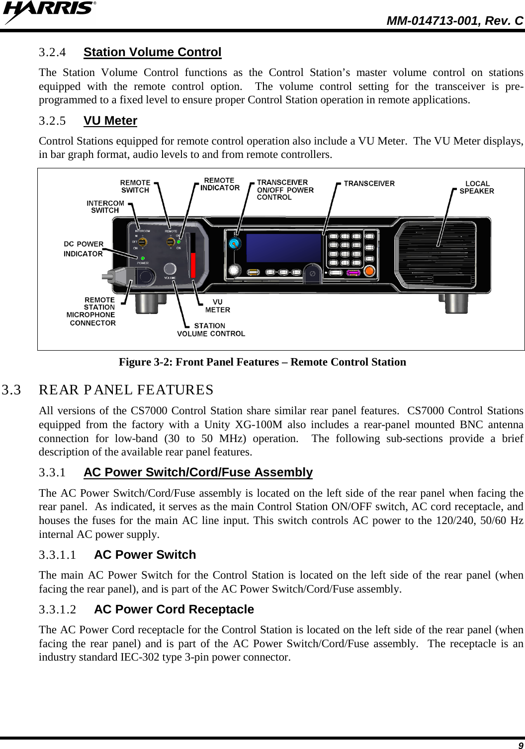
Harris RF Communications Division XG-100M00 Unity Multiband Mobile User Manual 1
Harris Corporation RF Communications Division Unity Multiband Mobile 1
UserManual.wiki
>
Harris RF Communications Division
>
XG-100M00 User Manual
>
User Manual 1
Contents
1.
Manual 1
2.
Manual 2
3.
Manual 3
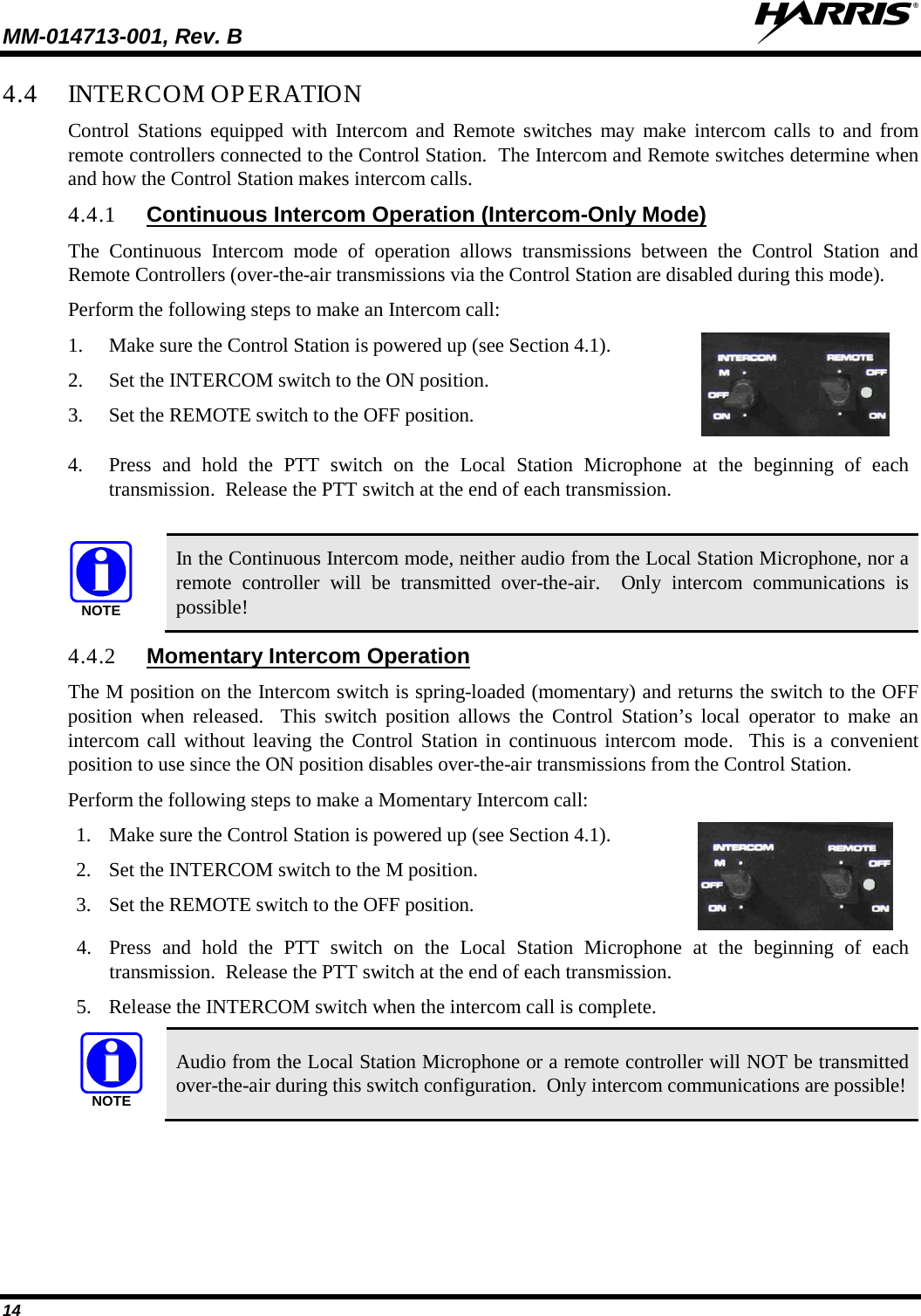
4.
manual 1
5.
manual 2
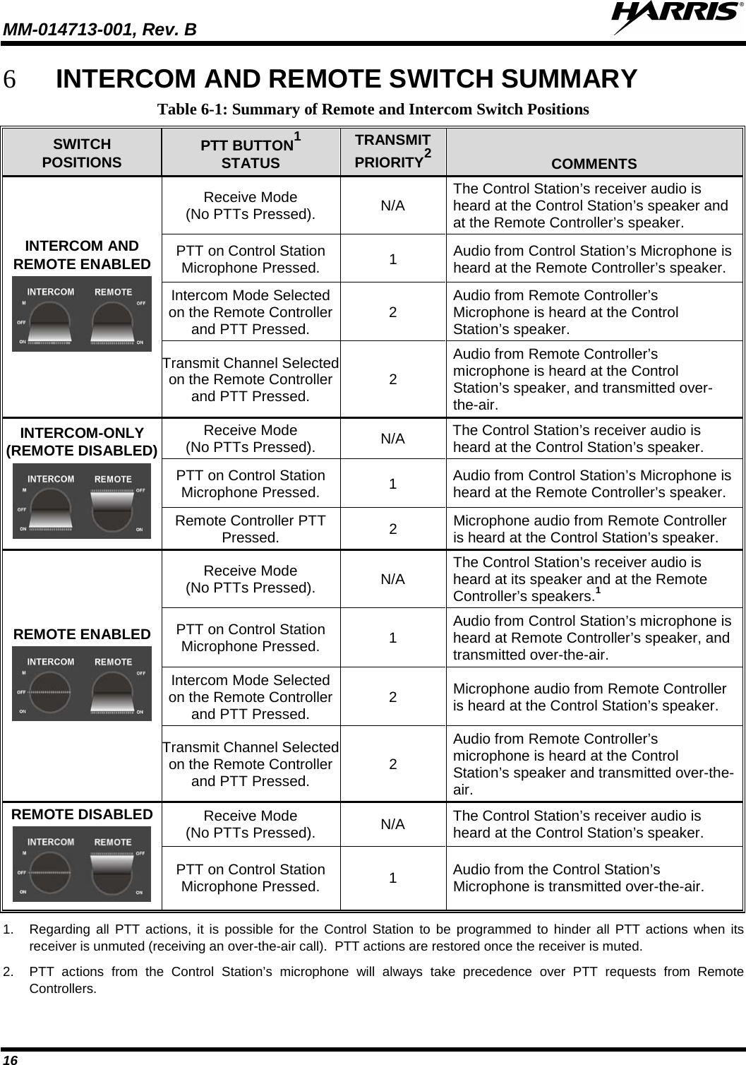
6.
manual 3
7.
User Manual 1
8.
User Manual 2
User Manual 1
Navigation menu
Upload a User Manual
Namespaces
Wiki Guide
HTML
PDF
Info
Views
User Manual
Discussion / Help
Navigation