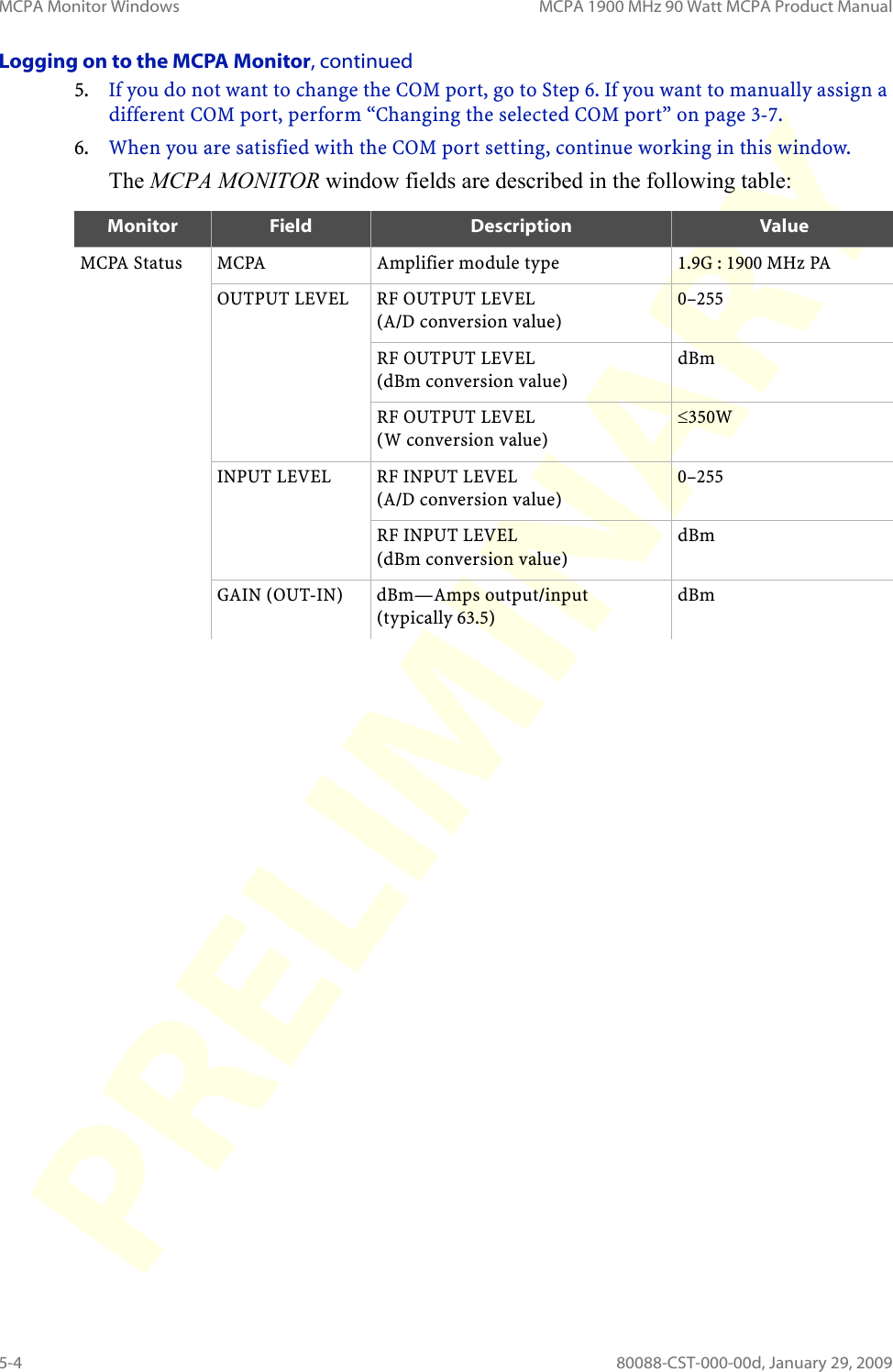
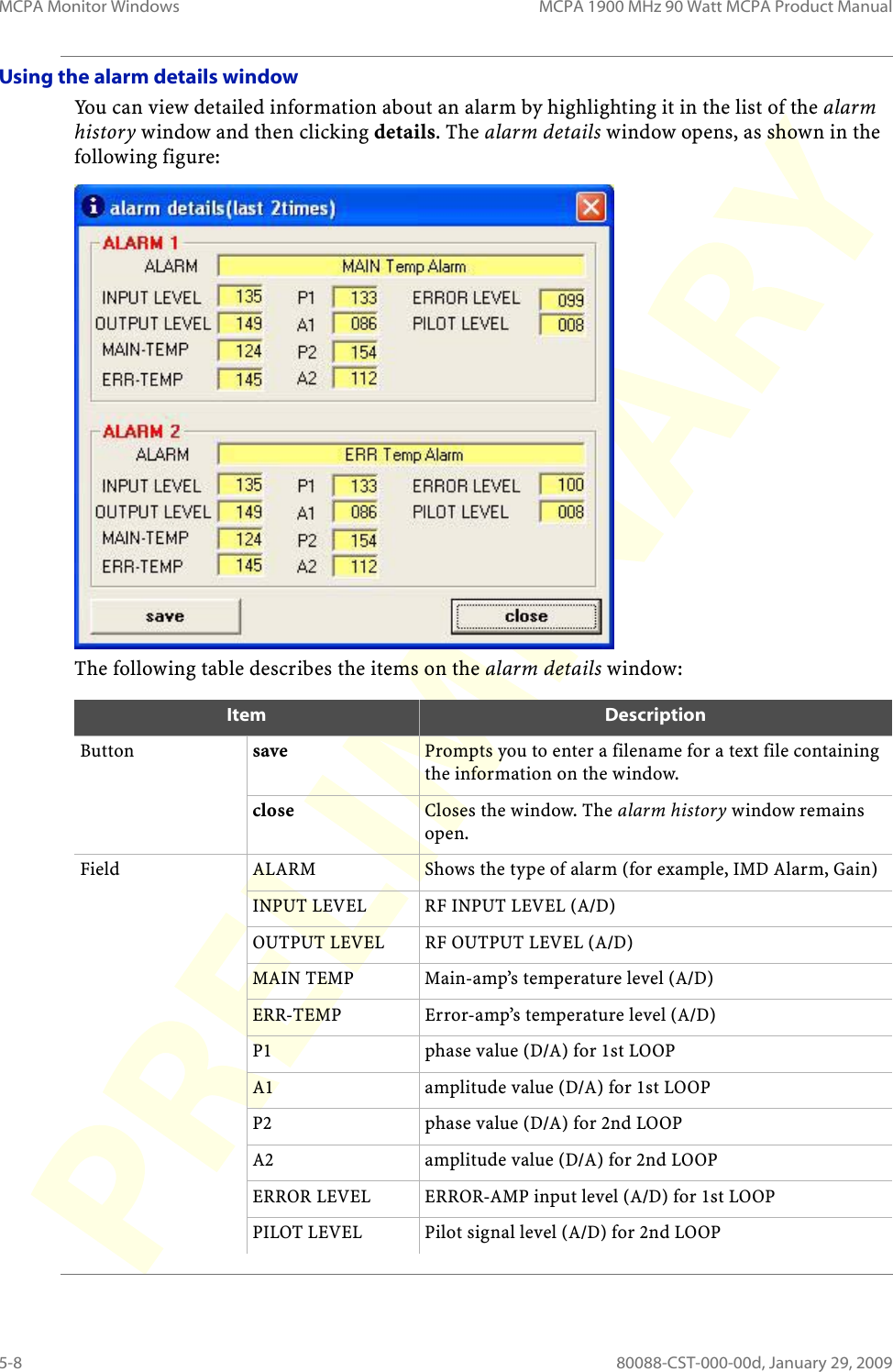
Hitachi Communication Technologies America USA-90121-KE-E Multi-Carrier Power Amplifier for GSM, EDGE, CDMA, WCDMA User Manual PD 80088 MCPA 950MHz 90W Ops

Hitachi Communication Technologies America, Inc Multi-Carrier Power Amplifier for GSM, EDGE, CDMA, WCDMA PD 80088 MCPA 950MHz 90W Ops

User Manual

80088-CST-000-00dJanuary 29, 2009Hitachi MCPA Series1900 MHz 90-Watt Amplifier Product Manual
FCC ComplianceHitachi wireless devices comply with Parts 15, 22, and 24 of the FCC Rules. Operation is subject to the following two conditions: this device may not cause harmful interference, andthis device must accept any interference received, including interference that may cause undesired operation.These devices comply with the limits for a Class A digital device in accordance with Part 15 of the FCC Rules. The limits stated in Part 15, Class A, of the FCC Rules are designed to provide reasonable protection against harmful interference when the equipment is operated in a commercial environment. This equipment generates, uses, and can radiate radio frequency energy, which may cause harmful interference to radio communications if not installed and operated as described in its associated documentation. Operating these devices in a residential area is likely to cause harmful interference, in which case the user is required to correct the interference at his own expense.Note:  Install the Multi-Carrier Power Amplifier (MCPA) in restricted access areas (dedicated equipment rooms, equipment closets, or the like) in accordance with articles 110-16, 110-17, and 110-18 of the National Electric Code; ANSI/NFPA 70.Any changes or modifications to the equipment or its enclosure must be expressly approved by Hitachi Telecom (USA), Inc. Otherwise, the user’s authority to operate this equipment may be voided by the FCC.Copyright Notice©2004-2009 Hitachi Kokusai Electric, Inc. and Hitachi Telecom (USA), Inc. All Rights Reserved. Printed in the United States of America. This edition (80088-CST-000-00d for Release 1.0, January 29, 2009) replaces previously dated versions of this document. Although this document was believed to be correct at the time of publication, Hitachi Telecom (USA), Inc., Hitachi Kokusai Electric, Inc., Hitachi America, Ltd., and their affiliates assume no responsibility for errors or omissions. Technical bulletins may be issued at any time to further clarify product installation, maintenance, use, and administration. In the event of any differences, the information in more recently issued technical bulletin supersedes correlative information in associated product documentation.For additional information about the products in this document, please contact: Hitachi Telecom (USA), Inc. 3617 Parkway Lane Norcross, GA 30092 Tel (770) 446-8820 Fax (770) 242-1414TrademarksAll trademarks and registered trademarks are the property of their respective owners.
MCPA 1900 MHz 90 Watt MCPA Product Manual80088-CST-000-00dJanuary 29, 2009
Revision HistoryThe following table identifies the history of revisions to this document, the MCPA 1900 MHz 90 Watt MCPA Product Manual (80088-CST-000-00d).1.Revision Date Revision LevelFor Product Release Summary of ChangesFebruary 2008 a 1.0 Initial draft for 19-inch rackFebruary 2008 b 1.0 Updated content from HIKEJanuary 6, 2009 a 1.0 Initial draftJanuary 7, 2009 b 1.0 Removed configuration-specific informationJanuary 13, 2009 c 1.0 Added new graphic, removed 850 MHz, moved COM port info to pragmatic location
80088-CST-000-00d, January 29, 2009 iiiList of TablesList of FiguresPrefaceAbout this Document . . . . . . . . . . . . . . . . . . . . . . . . . . . . . . . . . . . . . . . . . . . . . . . . . . . . . . . . . . . . . . . . . . . . . . . . xA Word about Safety Notices . . . . . . . . . . . . . . . . . . . . . . . . . . . . . . . . . . . . . . . . . . . . . . . . . . . . . . . . . . . . . . . .  xiIMPORTANT SAFETY NOTICES . . . . . . . . . . . . . . . . . . . . . . . . . . . . . . . . . . . . . . . . . . . . . . . . . . . . . . . . . . . . . . xiii1Product OverviewMCPA Overview. . . . . . . . . . . . . . . . . . . . . . . . . . . . . . . . . . . . . . . . . . . . . . . . . . . . . . . . . . . . . . . . . . . . . . . . . . . . 1-22 Equipment RequirementsElectrical Requirements . . . . . . . . . . . . . . . . . . . . . . . . . . . . . . . . . . . . . . . . . . . . . . . . . . . . . . . . . . . . . . . . . . . . 2-2Tools and Equipment  . . . . . . . . . . . . . . . . . . . . . . . . . . . . . . . . . . . . . . . . . . . . . . . . . . . . . . . . . . . . . . . . . . . . . . 2-33 Installing the MCPA MonitorSystem Configuration Requirements  . . . . . . . . . . . . . . . . . . . . . . . . . . . . . . . . . . . . . . . . . . . . . . . . . . . . . . . 3-2Installing the MCPA Monitor. . . . . . . . . . . . . . . . . . . . . . . . . . . . . . . . . . . . . . . . . . . . . . . . . . . . . . . . . . . . . . . . 3-34 Replacing MCPA ModulesReplacing the Fan Module. . . . . . . . . . . . . . . . . . . . . . . . . . . . . . . . . . . . . . . . . . . . . . . . . . . . . . . . . . . . . . . . . . 4-2Replacing the Amplifier Module . . . . . . . . . . . . . . . . . . . . . . . . . . . . . . . . . . . . . . . . . . . . . . . . . . . . . . . . . . . . 4-35 TroubleshootingTroubleshooting Overview . . . . . . . . . . . . . . . . . . . . . . . . . . . . . . . . . . . . . . . . . . . . . . . . . . . . . . . . . . . . . . . . . 5-2MCPA Monitor Windows  . . . . . . . . . . . . . . . . . . . . . . . . . . . . . . . . . . . . . . . . . . . . . . . . . . . . . . . . . . . . . . . . . . . 5-3Checking the LEDs . . . . . . . . . . . . . . . . . . . . . . . . . . . . . . . . . . . . . . . . . . . . . . . . . . . . . . . . . . . . . . . . . . . . . . . . . 5-9Problem Solving Matrix . . . . . . . . . . . . . . . . . . . . . . . . . . . . . . . . . . . . . . . . . . . . . . . . . . . . . . . . . . . . . . . . . . .5-106MCPA AlarmsMCPA Module Alarms . . . . . . . . . . . . . . . . . . . . . . . . . . . . . . . . . . . . . . . . . . . . . . . . . . . . . . . . . . . . . . . . . . . . . . 6-2Appendix A Appendix A: Technical Specifications for the 90 W MCPAPhysical and Environmental Specifications. . . . . . . . . . . . . . . . . . . . . . . . . . . . . . . . . . . . . . . . . . . . . . . . . .A-2Electrical Specifications . . . . . . . . . . . . . . . . . . . . . . . . . . . . . . . . . . . . . . . . . . . . . . . . . . . . . . . . . . . . . . . . . . . .A-3Appendix B Appendix B: Repair and Return ProceduresPolicies and Requirements  . . . . . . . . . . . . . . . . . . . . . . . . . . . . . . . . . . . . . . . . . . . . . . . . . . . . . . . . . . . . . . . . . B-2RMA Process and Procedures. . . . . . . . . . . . . . . . . . . . . . . . . . . . . . . . . . . . . . . . . . . . . . . . . . . . . . . . . . . . . . . B-3GlossaryWireless Industry and Hitachi Terms . . . . . . . . . . . . . . . . . . . . . . . . . . . . . . . . . . . . . . . . . . . . . . . . . . . . . .  GL-1TABLE OF CONTENTS
Table of Contents MCPA 1900 MHz 90 Watt MCPA Product Manualiv 80088-CST-000-00d January 29, 2009
80088-CST-000-00d, January 29, 2009 vTable 1-1: Labels on the MCPA module faceplate . . . . . . . . . . . . . . . . . . . . . . . . . . . . . . . . . . . . . . . . . . . . . . 1-2Table 2-1: Input power materials . . . . . . . . . . . . . . . . . . . . . . . . . . . . . . . . . . . . . . . . . . . . . . . . . . . . . . . . . . . . . . 2-3Table 2-2: RF cables. . . . . . . . . . . . . . . . . . . . . . . . . . . . . . . . . . . . . . . . . . . . . . . . . . . . . . . . . . . . . . . . . . . . . . . . . . . 2-3Table 2-3: Torque settings for connectors and screws . . . . . . . . . . . . . . . . . . . . . . . . . . . . . . . . . . . . . . . . . . 2-5Table 2-4: AWG Guidelines . . . . . . . . . . . . . . . . . . . . . . . . . . . . . . . . . . . . . . . . . . . . . . . . . . . . . . . . . . . . . . . . . . . . 2-6Table 5-1: Verification check points  . . . . . . . . . . . . . . . . . . . . . . . . . . . . . . . . . . . . . . . . . . . . . . . . . . . . . . . . . . . 5-9Table 5-2: Problems & solutions . . . . . . . . . . . . . . . . . . . . . . . . . . . . . . . . . . . . . . . . . . . . . . . . . . . . . . . . . . . . . .5-10Table 6-1: MCPA module alarms. . . . . . . . . . . . . . . . . . . . . . . . . . . . . . . . . . . . . . . . . . . . . . . . . . . . . . . . . . . . . . . 6-2Table A-1: Physical & environmental specifications. . . . . . . . . . . . . . . . . . . . . . . . . . . . . . . . . . . . . . . . . . . . .A-2Table A-2: Common transmit electrical specifications . . . . . . . . . . . . . . . . . . . . . . . . . . . . . . . . . . . . . . . . . .A-3LIST OF TABLES
List of Tables MCPA 1900 MHz 90 Watt MCPA Product Manualvi 80088-CST-000-00d January 29, 2009
80088-CST-000-00d, January 29, 2009 viiFigure 1-1: MCPA module (front). . . . . . . . . . . . . . . . . . . . . . . . . . . . . . . . . . . . . . . . . . . . . . . . . . . . . . . . . . . . . . 1-2Figure 1-2: MCPA module (back). . . . . . . . . . . . . . . . . . . . . . . . . . . . . . . . . . . . . . . . . . . . . . . . . . . . . . . . . . . . . . 1-3Figure 2-1: Torque screwdriver and wrenches . . . . . . . . . . . . . . . . . . . . . . . . . . . . . . . . . . . . . . . . . . . . . . . . . 2-4Figure 4-1: Replacing the Fan module  . . . . . . . . . . . . . . . . . . . . . . . . . . . . . . . . . . . . . . . . . . . . . . . . . . . . . . . . 4-2Figure 4-2: MCPA module (front). . . . . . . . . . . . . . . . . . . . . . . . . . . . . . . . . . . . . . . . . . . . . . . . . . . . . . . . . . . . . . 4-3Figure B-1: Return Material Authorization (RMA) process . . . . . . . . . . . . . . . . . . . . . . . . . . . . . . . . . . . . . .B-3LIST OF FIGURES
List of Figures MCPA 1900 MHz 90 Watt MCPA Product Manualviii 80088-CST-000-00d January 29, 2009
80088-CST-000-00d, January 29, 2009 ixPREFACEPlease read this Preface to learn important information about using this document and the product(s) that it describes. The Preface contains general information about this document as well as important safety notices.ContentsTopics covered in the Preface include: PageAbout this Document. . . . . . . . . . . . . . . . . . . . . . . . . . . . . . . . . . . . . . . . . . . . . . . . . . . . . . . . . . . . .xA Word about Safety Notices  . . . . . . . . . . . . . . . . . . . . . . . . . . . . . . . . . . . . . . . . . . . . . . . . . . . . . xiIMPORTANT SAFETY NOTICES. . . . . . . . . . . . . . . . . . . . . . . . . . . . . . . . . . . . . . . . . . . . . . . . . .xiii
About this Document MCPA 1900 MHz 90 Watt MCPA Product Manualx80088-CST-000-00d, January 29, 2009About this DocumentThis section provides some general information that you need to know when using this document. PurposeThis document describes the Multi-Carrier Power Amplifier (MCPA) module. Intended audienceThis document is intended for individuals involved in the operations of the Multi-Carrier Power Amplifier (MCPA). How this document is organizedThe following table summarizes the organization of this document:Document feedbackAt Hitachi, we strive to produce high-quality documentation, and we welcome your feedback. If you have comments or suggestions about our documents, please send us an e-mail. Please include the following information with your feedback:Product name and version number Document name Document date Page number Brief description of the content, noting whether you noticed step-by-step instructions that are inaccurate, information that requires clarification or more details, etc.Your suggestion(s) for how to correct or improve the documentPlease send e-mail messages to documentation_mgr@hitel.com. This e-mail address is only for documentation feedback. If you have a technical question, please contact Technical Support as described in “Technical support” on page xv.Chapter DescriptionPreface Information about this document: its purpose, intended audiences, and organization1An introduction to the MCPA Amplifier module2Materals, tools, and equipment needed for the MCPA Amplifier module3Procedures for installing the MCPA Monitor software4Procedures for replacing MCPA Amplifier parts5Procedures for troubleshooting the MCPA Amplifier7Systems alarms on the MCPA Amplifier moduleAppendix A Technical specificationsAppendix B Repair and Return ProceduresGlossary Definitions of terms used in this documentIndex An index of the information in this document
80088-CST-000-00d, January 29, 2009 xiA Word about Safety NoticesThis section describes how different types of safety notices are presented in this document.Hazardous conditionsThis document includes safety notices that emphasize the potential for these hazardous conditions:DangerWar ningCautionThe hazards typically involve situations where installers handle:Electrical powerCircuit packsDanger messageDanger messages indicate you are in the presence of a hazard that will cause death or severe personal injury if the hazard is not avoided. This document uses the following format to indicate Danger messages:Warning message War ni ng messages indicate that you are in the presence of a hazard that may cause death or severe personal injury if the hazard is not avoided. This document uses the following format to indicate War n in g  messages:IMPORTANT!Comply with all danger, warning, and caution statements in this document. DANGER!Text describing the hazardous condition.WARNING!Text describing the hazardous condition.
A Word about Safety Notices MCPA 1900 MHz 90 Watt MCPA Product Manualxii 80088-CST-000-00d, January 29, 2009Caution messageCaution messages indicate the presence of a hazard that may cause personal injury or property damage if the hazard is not avoided. Property damage includes:Equipment damage or malfunctionLoss of software or dataService interruptionThis document uses the following format to indicate Caution messages:Important messageImportant messages indicate information that is important to the successful and/or efficient operation of the product, including:Settings for the hardware or software to avoid conflict with other devicesConfiguration information to ensure maximum efficiencyReminders to verify that vital prerequisite processes have been completedThis document uses the following format to indicate Important messages: CAUTION!Text describing the hazardous condition.IMPORTANT!Text describing necessary information.
 IMPORTANT SAFETY NOTICES80088-CST-000-00d, January 29, 2009 xiiiIMPORTANT SAFETY NOTICESThis section contains important information about safely operating the MCPA.General safety instructionsWhen handling equipment described in this document, adhere to the following safety instructions, and follow all warnings and instructions marked on the product.continued...IMPORTANT!Before installing, operating, or maintaining the MCPA, please read this entire document carefully. Safe and efficient use of your MCPA depends upon careful reading of this document. Be sure to carefully follow all instructions that accompany this product. Pay particular attention to safety statements, and keep this document for future reference.CAUTION!Prevent equipment damage or malfunction by adhering to the following instructions:• Do not attempt to perform any repairs on this equipment. Only technicians who have been professionally trained on this equipment are qualified to perform such operations. • Disassembling or modifying this product except as described in procedures provided by Hitachi voids the product warranty. • Do not place this product on an unstable or inclined surface.• Do not place or use a magnet or any type of magnetic device on or near this equipment. Magnetic and static devices can affect the operation of this equipment.• Do not expose this equipment to liquid, moisture, or oily vapor of any kind, under any circumstance.• Check that all fuses and circuit breakers used with this equipment meet the voltage, current, and power specifications provided in this document.• The MCPA may not work properly if you use insufficient torque on it. Excess torque may damage the product. For torque requirements, see Table 2-4, “Torque settings for connectors and screws,” on page 2-8.
IMPORTANT SAFETY NOTICES MCPA 1900 MHz 90 Watt MCPA Product Manualxiv 80088-CST-000-00d, January 29, 2009General safety instructions, continuedWARNING!Improper handling or placement of this product may cause a fire or electrical hazard or other personal injury risks. Avoid risk of personal injury by adhering to the following instructions:• Do not place this product in an enclosure, except as provided in the installation instructions. This product requires adequate ventilation to avoid overheating and risk of fire.• Do not block or cover the slots or openings in the product.• Do not place anything on top of the product.• Do not place this product in direct sunlight or in a high temperature area unless it is in the provided enclosure.• Depending on the lifting and weight restrictions at your workplace, installing or replacing the MCPA in the rack may require the use of lifting equipment and/or the efforts of more than one person. Refer to your company’s guidelines.• To avoid possible damage to the MCPA due to condensation, do not apply power to the MCPA until after it has been in its operating environment without power for a minimum of 30 minutes prior to applying power.• Check that all fuses and circuit breakers used with this equipment meet the voltage, current, and power specifications provided in this document.DANGER!Opening or removing covers and/or circuit packs may expose you to dangerous voltages. Avoid the risk of electric shock or damage to electrical components by adhering to the following instructions:• Use extreme caution whenever applying or removing DC power. When removing DC power, the cable has a residual DC charge that could arc, which could cause electrocution and/or death. Follow your company’s safety practices for handling DC voltage.• While installing this product, make sure that the product is disconnected from its power source. Before applying power, check that the ground is properly connected to the unit.• If using a 7/16 DIN-type to N-type adapter, only disconnect the adapter when the RF power is off to avoid electrical arcing, physical injury, and/or damage to the equipment.•If your hands are wet, do not touch the power terminal board or any power wires.• Do not power this equipment from any power source other than the type that is indicated on the product labels.• Do not insert any object through any slots or holes in the equipment or enclosure.• Remove power at the main breaker before performing any work on this product.• Remain aware of the hazards involved when working with electrical and RF circuitry and be sure to follow standard practices for preventing accidents.
 IMPORTANT SAFETY NOTICES80088-CST-000-00d, January 29, 2009 xvIndustry Canada application noticeThe Manufacturer's rated output power of this equipment is for single carrier operation. When the MCPA requires serviceOnly service personnel trained to install and remove this equipment are authorized to move this product to a different location. All service must be performed by trained personnel only. Covers for this product can only be removed by trained service personnel.Disassembling or modifying this product except as described in procedures provided by Hitachi voids the product warranty.If service is required, contact your Field Engineer or Hitachi Technical Assistance Center (TAC) at 770-446-8836 for instructions. Service is required when any of the following circumstances occurs:There is damage to the equipment.There is smoke or odor coming from the product.Liquid enters the equipment.A heavy object falls on the equipment.Operation is not normal as described in these instructions.The equipment gets dropped or falls.Technical supportAfter following the procedures in this document, if the product is still not functioning properly, contact the Hitachi Technical Assistance Center (TAC) at 770-446-8836.Cleaning instructionsFollow these guidelines when attempting to clean the equipment.CAUTION!For situations when multiple carrier signals are present, the rating would have to be reduced by 3.5 dB, especially where the output signal is re-radiated and can cause interference to adjacent band users. This power reduction is to be by means of input power or gain reduction and not by an attenuator at the output of the device.IMPORTANTDo not return equipment for warranty or repair service until you have received proper shipping instructions from Hitachi.WARNING!Improper cleaning can cause damage to the equipment. To prevent inadvertently damaging the equipment during cleaning, follow these guidelines when cleaning the equipment or in its vicinity:• Do not use a liquid cleaner, solvent, or an aerosol cleaner.• Use only blown air or equipment that has been specially designed for cleaning computer equipment to clean this equipment.• Surfaces may be cleaned with a soft, dry cloth.
IMPORTANT SAFETY NOTICES MCPA 1900 MHz 90 Watt MCPA Product Manualxvi 80088-CST-000-00d, January 29, 2009
80088-CST-000-00d, January 29, 2009 1-11PRODUCT OVERVIEWThis chapter provides an overview of the Hitachi Multi-Carrier Power Amplifier (MCPA) and its components. ContentsTopics covered in this chapter include: PageMCPA Overview  . . . . . . . . . . . . . . . . . . . . . . . . . . . . . . . . . . . . . . . . . . . . . . . . . . . . . . . . . . . . . . . 1-2Note: The first topic begins on the following page.
MCPA Overview MCPA 1900 MHz 90 Watt MCPA Product Manual1-2 80088-CST-000-00d, January 29, 2009MCPA OverviewThe Hitachi Multi-Carrier Power Amplifier (MCPA) increases the number of carriers per cell site without requiring additional feeder lines or antennas, and expands the coverage and capacity of the cell site. MCPA moduleThe MCPA module boosts the combined radio signal to a high power using linearization and high-efficiency methods to maintain signal quality. The following figure shows the front of the MCPA module.Figure 1-1:  MCPA module (front)The labels on the front of the MCPA module are described in the following table:continued...Table 1-1:  Labels on the MCPA module faceplateLabel DescriptionOUT RF output connector (N-type Female)IN RF input connector (SMA-type Female)ONOFFCircuit Breaker•ON: Power ON•OFF: Power OFFACT Active LED: Green indicates the MCPA module is activeALM Alarm LED: Red indicates an MCPA module alarmRF Output RF InputCircuit breakerActive LEDAlarm LEDMaintenance Port
Product Overview MCPA Overview80088-CST-000-00d, January 29, 2009 1-3MCPA module, continuedThe following figure shows the back of the MCPA module:Figure 1-2:  MCPA module (back)
MCPA Overview MCPA 1900 MHz 90 Watt MCPA Product Manual1-4 80088-CST-000-00d, January 29, 2009
80088-CST-000-00d, January 29, 2009 2-12EQUIPMENT REQUIREMENTSThis chapter lists the tools and equipment needed to successfully install the Hitachi Multi-Carrier Power Amplifier (MCPA).ContentsTopics covered in this chapter include: PageElectrical Requirements  . . . . . . . . . . . . . . . . . . . . . . . . . . . . . . . . . . . . . . . . . . . . . . . . . . . . . . . . 2-2Tools and Equipme nt . . . . . . . . . . . . . . . . . . . . . . . . . . . . . . . . . . . . . . . . . . . . . . . . . . . . . . . . . . . 2-3Tools require d  . . . . . . . . . . . . . . . . . . . . . . . . . . . . . . . . . . . . . . . . . . . . . . . . . . . . . . . . . . . . . 2-4Torque setting guidelines for connectors and screws . . . . . . . . . . . . . . . . . . . . . . . . . . . . 2-5AWG guidelines . . . . . . . . . . . . . . . . . . . . . . . . . . . . . . . . . . . . . . . . . . . . . . . . . . . . . . . . . . . . 2-6Note: The first topic begins on the following page.
Electrical Requirements MCPA 1900 MHz 90 Watt MCPA Product Manual2-2 80088-CST-000-00d, January 29, 2009Electrical RequirementsEach Amplifier module installed in the subrack requires a separate circuit. The maximum current draw of each Amplifier module is 25A @ +27 VDC (675 W).Note: The Amplifier module circuit breaker is rated for 30A. For DC cable requirements, refer to “AWG guidelines” on page 2-6.
Equipment Requirements Tools and Equipment80088-CST-000-00d, January 29, 2009 2-3Tools and EquipmentThis section describes the materials, tools, equipment, and preparation work required to install an MCPA system. Input power and grounding materialsThe following table lists input and grounding materials typically required:RF cable requirementsThe following table shows the RF cable requirements:IMPORTANT!The following tables are intended to identify typical items provided by the installer or the customer. Review the scope of work, the individual site survey, and the installation plan to determine the quantity and size of each item as well as whether other items may be necessary.Table 2-1:  Input power materialsItem Description/PurposeInput breakers from the main +27 VDC power source 30-amp breakers per installed MCPA module aa. For detailed requirements, refer to “AWG guidelines” on page 2-6. Table 2-2:  RF cablesItem Description/PurposeN-type Male hex head connector For 1/2" Low loss RF cable. Used for connecting external equipment.SMA connector
Tools and Equipment MCPA 1900 MHz 90 Watt MCPA Product Manual2-4 80088-CST-000-00d, January 29, 2009Tools requiredIn addition to the items listed in the preceding tables, you should have a telecommunications installer’s kit which includes the following items:Calibrated torque screwdrivers for TORX 25 screws, if required for other equipmentCalibrated torque wrenches for RF cables (SMA-type, N-type, 7/16 DIN-type)Calibrated RF power meter with appropriate sensorsHigh-power (500W) 30 dB attenuatorsCalibrated compression crimpers with an assortment of crimp sizes, if neededCalibrated voltmeterSafety equipment per customer requirements, such as hard hat and glovesFigure 2-1 shows the torque screwdriver and wrenches you may need for the installation.Figure 2-1:  Torque screwdriver and wrenchesIMPORTANTYou should have torque wrenches that can be calibrated to the recommended torque for each type of connector.
Equipment Requirements Tools and Equipment80088-CST-000-00d, January 29, 2009 2-5Torque setting guidelines for connectors and screwsThe following table provides the recommended torque settings for connectors and screws when installing the MCPA equipment:Table 2-3:  Torque settings for connectors and screwsItem Torque rangeConnector typeSMA 0.5 to 0.7 N-m (4.5 to 6.0 lbf in)N 1.3 to 1.7 N-m (11.5 to 15 lbf in)7/16 DIN 25 to 30 N-m (221 to 265 lbf in), typicalScrew T25  2.4 to 3.4 N-m (21.2 to 30.1 lbf in), typicalCAUTION!Excess tightening can damage connectors. You can tighten the N-type RF connectors by hand. Under-tightening the connectors does not damage the product, but it may not work properly if the connectors are under tightened.
Tools and Equipment MCPA 1900 MHz 90 Watt MCPA Product Manual2-6 80088-CST-000-00d, January 29, 2009AWG guidelinesThe following table provides guidelines for using the appropriate AWG cable. These guidelines are based on the distance to be covered and the voltage drop.Note: Recommended size for frame grounding cable is 6 AWG.Table 2-4:  AWG GuidelinesAWG 1900 MHz Single MCPA module/Sector Max. Run (Ft.)10 5.188.1613.0420.5232.81/0 52.2 Breaker Rating 30Max Current 25
80088-CST-000-00d, January 29, 2009 3-13 INSTALLING THE MCPA MONITOR This chapter lists required system hardware and software, and provides instructions for installing the MCPA Monitor software from the CD-ROM to a Windows XP® PC.ContentsTopics covered in this chapter include: PageSystem Configuration Requirements. . . . . . . . . . . . . . . . . . . . . . . . . . . . . . . . . . . . . . . . . . . . . . 3-2Installing the MCPA Monitor  . . . . . . . . . . . . . . . . . . . . . . . . . . . . . . . . . . . . . . . . . . . . . . . . . . . . 3-3Note: The first topic begins on the following page.
System Configuration Requirements MCPA 1900 MHz 90 Watt MCPA Product Manual3-2 80088-CST-000-00d, January 29, 2009System Configuration RequirementsA PC is required for connecting to a Hitachi Multi-Carrier Power Amplifier to run the MCPA Monitor software. You can only connect to one MCPA at a time. The MCPA Monitor software cannot monitor more than one MCPA concurrently.The following software is required:Microsoft Windows XP® (SP-2)  orWindows 2000The following configurations are recommended:Windows XP:PC: Processor clock ≥300 MHzRAM: ≥128 MBHDD: ≥2.1 GBWindows 2000:PC: Processor clock ≥133 MHzRAM: ≥64 MBHDD: ≥2.1 GBIMPORTANT!The computer you use with the MCPA Monitor must have a DB-9 serial (RS-232) port with a logical COM port to connect to the MCPA. If your computer does not have a serial port, you can use a high-speed USB-to-serial adapter with software that creates a virtual COM port connection for the adapter, also known as a smart USB-to-RS232 adapter. Follow the manufacturer’s installation instructions that accompany the device before installing the MCPA Monitor software, and be sure the adapter is connected to the same COM port each time you use it to connect to the MCPA Monitor.
3 Installing the MCPA Monitor Installing the MCPA Monitor80088-CST-000-00d, January 29, 2009 3-3Installing the MCPA MonitorFollow these procedures to install the MCPA Monitor software.Using the InstallShield Wizard to install the MCPA MonitorPerform the following steps to install the MCPA Monitor.1. Uninstall any previous verisons of the MCPA Monitor that are on your computer.2. If you are using a CD or other removable media to install the MCPA Monitor, insert it now.3. Navigate to the path containing the executable (.exe) file for the MCPA Monitor (i.e., setup.exe).4. Double-click the executable (.exe) file. InstallShield prepares the wizard to guide you through the installation. The Welcome window opens.continued...IMPORTANT!Before you install the current release of the MCPA Monitor, you must uninstall any previous versions of the MCPA Monitor.
Installing the MCPA Monitor MCPA 1900 MHz 90 Watt MCPA Product Manual3-4 80088-CST-000-00d, January 29, 2009Using the InstallShield Wizard to install the MCPA Monitor, continued5. Click Next. The User Information window opens.6. Type your name and the name of your company, and then click Next. The Choose Destination Location window opens. Use this window to specify the location where you want to install the MCPA Monitor:To install to the default directory, click Next. To install to another directory, click Browse, select another directory, and then click Next.continued...
3 Installing the MCPA Monitor Installing the MCPA Monitor80088-CST-000-00d, January 29, 2009 3-5Using the InstallShield Wizard to install the MCPA Monitor, continuedThe Select Program Folder window opens.7. Select the folder you want the program icons installed to, and then click Next. The Start Copying Files window opens.If you are satisfied with the settings displayed, click Next. Otherwise, click Back, make changes to settings on previous windows as desired, click Next until you return to the Start Copying Files window, and then click Next.continued...
Installing the MCPA Monitor MCPA 1900 MHz 90 Watt MCPA Product Manual3-6 80088-CST-000-00d, January 29, 2009Using the InstallShield Wizard to install the MCPA Monitor, continued8. The program files are copied to the destination folder. When the copy process is complete, the Setup Complete window opens.Note: The Setup Complete window may vary slightly depending upon your computer configuration and previous installation(s) of the MCPA Monitor.9. If you choose not to restart your computer at this time, the Setup Complete window displays as follows:10. Click Finish. You have successfully installed the MCPA Monitor.
3 Installing the MCPA Monitor Installing the MCPA Monitor80088-CST-000-00d, January 29, 2009 3-7Changing the selected COM portIf you want to use a different COM port for the MCPA Monitor, or if at any point the MCPA MONITOR loses communication with the MCPA, perform this procedure.Note: This does not change a configuration in the MCPA Monitor software. It is a runtime-only change. Therefore, if you change the COM port, you will have to change it each time you run the MCPA Monitor. If you use a USB-to-serial adapter, consider labeling your USB-to-serial adapter or the computer on which your run the MCPA Monitor with the COM port number used by the USB-to-serial adapter.1. With the MCPA MONITOR window open, press <Alt>+C. The Select COM Port window opens indicating the currently active COM port and other enabled COM ports as options. 2. Select a different COM port, and then click COM Set. 3. Click Cancel to close this window and return to the MCPA MONITOR window.
Installing the MCPA Monitor MCPA 1900 MHz 90 Watt MCPA Product Manual3-8 80088-CST-000-00d, January 29, 2009
80088-CST-000-00d, January 29, 2009 4-14 REPLACING MCPA MODULESUse this chapter to replace the MCPA modules, if necessary.ContentsTopics covered in this chapter include: PageReplacing the Fan Module. . . . . . . . . . . . . . . . . . . . . . . . . . . . . . . . . . . . . . . . . . . . . . . . . . . . . . . 4-2Replacing the Amplifier Module  . . . . . . . . . . . . . . . . . . . . . . . . . . . . . . . . . . . . . . . . . . . . . . . . . 4-3Note: The first topic begins on the following page.1.WARNING!• Be careful not to drop the modules during replacement work. • Use work gloves to prevent injury when replacing equipment.• Make sure that all bolts and screws are properly tightened.• In the event that any RF connector must be removed during maintenance, turn off all power to the affected equipment. CAUTION!• Minimize the time during which the fan is stopped. The temperature of the Amplifier module will continue to rise and result in a temperature shutdown if the fan is not returned to operation in a timely manner.• Check that the Tx input signal does not exceed the specified value. Damage to the product may occur.
Replacing the Fan Module MCPA 1900 MHz 90 Watt MCPA Product Manual4-2 80088-CST-000-00d, January 29, 2009Replacing the Fan ModuleThis section provides instructions for replacing the Fan module.Replacing the fan moduleComplete these steps to replace the fan module:1. Power OFF the Amplifier module, if desired. You can hot-swap the fan.2. Remove the two mounting screws at the top of the module, and the two mounting screws at the bottom of the module to detach the Fan module.3. Insert the replacement Fan module so that the connector is on the left side of the unit, and replace the mounting scsrews at the top and bottom of the module .4. Power ON the Amplifier module and confirm that the ACT LED is lit green.Figure 4-1:  Replacing the Fan moduleCAUTION!• This product is equipped with a cooling fan. To avoid personal injury, replace the FAN module with the power turned OFF. Note: The FAN module can be replaced with the power ON if the replacement can be completed within one (1) minute. If replacement of a running fan is not completed within one minute, the MCPA module may shut down due to an excessive temperature alarm.• Contact with the Fan connector can result in electric shock.• Do not insert any item through the fin guard or inside the connector when handling the Fan module.CAUTION!• Be careful handling the Fan module when it is exposed. Use work gloves to prevent injury.
4 Replacing MCPA Modules Replacing the Amplifier Module80088-CST-000-00d, January 29, 2009 4-3Replacing the Amplifier ModuleTo replace the Amplifier module, follow the steps below in the exact order shown. Replacing the Amplifier moduleComplete these steps to replace the Amplifier module:1. Power OFF the Amplifier module. 2. When Amplifier module has cooled, remove the RF input cable, the RF output cable, and the captive screws (TORX type T25) at the top and bottom of the Amplifier module. 3. Remove the Amplifier module.4. Install the replacement Amplifier module and secure it using the captive screws.5. Connect the RF input and RF output cables, tightening the connectors.6. Power ON and confirm the Amplifier module ACT LED is lit green.Figure 4-2:  MCPA module (front)CAUTION!• After powering off, the temperature of the Amplifier module will still be very hot, so handle with care. Do not begin replacement until the unit has cooled. • The Amplifier module weighs approximately 13.5 kg (29.8 lbs). Use caution when handling and use work gloves to prevent injury.RF Output RF InputPowerACT LEDAlarm LEDMaintenance Port
Replacing the Amplifier Module MCPA 1900 MHz 90 Watt MCPA Product Manual4-4 80088-CST-000-00d, January 29, 2009
80088-CST-000-00d, January 29, 2009 5-15 TROUBLESHOOTINGThis chapter describes how to use the information on the MCPA Monitor windows, together with the LEDs on the components, to find and resolve problems with the MCPA.ContentsTopics covered in this chapter include: PageTroubleshooting Overview . . . . . . . . . . . . . . . . . . . . . . . . . . . . . . . . . . . . . . . . . . . . . . . . . . . . . . 5-2MCPA Monitor Windows . . . . . . . . . . . . . . . . . . . . . . . . . . . . . . . . . . . . . . . . . . . . . . . . . . . . . . . . 5-3Checking the LEDs . . . . . . . . . . . . . . . . . . . . . . . . . . . . . . . . . . . . . . . . . . . . . . . . . . . . . . . . . . . . . 5-9Problem Solving Matrix. . . . . . . . . . . . . . . . . . . . . . . . . . . . . . . . . . . . . . . . . . . . . . . . . . . . . . . . 5-10Note: The first topic begins on the following page.
Troubleshooting Overview MCPA 1900 MHz 90 Watt MCPA Product Manual5-2 80088-CST-000-00d, January 29, 2009Troubleshooting OverviewThe MCPA provides two sources of information for determining and resolving problems in the individual components; the MCPA Monitor software and the LEDs on the units. Most alarms can be resolved without contacting technical support by using these tools and referring to the “Problem Solving Matrix” on page 5-10. Troubleshooting flowchartThe following table describes the process for locating problems on the MCPA:
5 Troubleshooting MCPA Monitor Windows80088-CST-000-00d, January 29, 2009 5-3MCPA Monitor WindowsThis section describes how to log on to the MCPA Monitor and use the information on the windows to troubleshoot your Multi-Carrier Power Amplifier.Logging on to the MCPA MonitorTo log on to the MCPA Monitor, follow these steps:1. Log on to your PC by typing your username and password.2. Connect your PC to the USB port on the Amplifier using the maintenance cable. 3. Launch the MCPA Monitor. If more than one COM port is enabled, the lowest number COM port is automatically selected, and an Initial COM Port Set message opens. The COM port must be COM5 or lower. If the Initial COM Port Set message does not open, there is only one COM port enabled. Note: This example indicates that more than one COM port is enabled, with the lowest enabled port number being COM5. If you are using a USB-to-serial adapter and a COM port number of 6 or higher is assigned, you must use your computer’s Device Manager to reassign the COM port. 4. Click OK to close the Initial COM Port Set message. The MCPA Monitor window opens.continued...IMPORTANT!Do not disconnect the USB-to-serial adapter while the MCPA MONITOR window is open. Doing so can cause the MCPA MONITOR to stop abruptly.
MCPA Monitor Windows MCPA 1900 MHz 90 Watt MCPA Product Manual5-4 80088-CST-000-00d, January 29, 2009Logging on to the MCPA Monitor, continued5. If you do not want to change the COM port, go to Step 6. If you want to manually assign a different COM port, perform “Changing the selected COM port” on page 3-7.6. When you are satisfied with the COM port setting, continue working in this window.The MCPA MONITOR window fields are described in the following table:Monitor Field Description  ValueMCPA Status  MCPA Amplifier module type 1.9G : 1900 MHz PAOUTPUT LEVEL RF OUTPUT LEVEL(A/D conversion value)0–255RF OUTPUT LEVEL (dBm conversion value)dBmRF OUTPUT LEVEL (W conversion value)≤350WINPUT LEVEL RF INPUT LEVEL (A/D conversion value)0–255RF INPUT LEVEL(dBm conversion value)dBmGAIN (OUT-IN) dBm—Amps output/input (typically 63.5)dBm
5 Troubleshooting MCPA Monitor Windows80088-CST-000-00d, January 29, 2009 5-5MCPA Status, ContinuedALARM The code of alarms that have occurred(Click alarm code field to display the alarm type.)0000 : No Alarm0001 : Gain Alarm0002 : Input Overdrive (MAJOR)0004 : IMD Alarm0008 : MAIN Temp Alarm0010 : Pilot Unlock Alarm0040 : ERR Temp Alarm0080 : Power Supply0100 : Relay Alarm0200 : FAN Alarm (MINOR)0400 : Input Overdrive (MINOR)0800 : MAIN Temp (MINOR)1000 : ERR Temp (MINOR)2000 : Power Supply (MINOR)PS LEVEL  (27V INPUT)PS Voltage level (A/D) 0–255MAIN-TEMP LEVELMain-amp’s temperature level (A/D)ERR-TEMP LEVEL Error-amp’s temperature level (A/D)•Recv timeout (red)•Communicate (green)Communication state between PA and Maintenance tool•Red background: The Communication is FALSE.• Green background: The Communication is TRUE•AMP:ON (green)•AMP:OFF (yellow)Amplification state: • Green indicates that the Amplifier is ENABLEd.• Yellow indicates that the Amplifier is DISABLEd.Firm:  The version of firmware currently runningVer.xx.xxHard:  The version of the hardware being usedVer.xx.xx1st Loop  ERROR LEVEL ERROR-AMP input level (A/D) 0–255PHASE (P1) phase value (D/A)AMPLITUDE (A1) amplitude value (D/A)Monitor Field Description  Value
MCPA Monitor Windows MCPA 1900 MHz 90 Watt MCPA Product Manual5-6 80088-CST-000-00d, January 29, 20092nd Loop  PILOT LEVEL Pilot signal level (A/D) 0–255PHASE (P2) phase value (D/A)AMPLITUDE (A2) amplitude value D/AALARM LOG button Click to display the alarm history windowMonitor Field Description  Value
5 Troubleshooting MCPA Monitor Windows80088-CST-000-00d, January 29, 2009 5-7Using the alarm history windowThe following figure is an example of various types of alarms the MCPA MONITOR window can display:Open the alarm history window by clicking ALARM LOG in the MCPA MONITOR window. The following figure shows a sample alarm history window:Item DescriptionField Count The total number of alarms that have occurred.alarms A brief description of the alarms that have occurred. NEW (1) is the most recent alarm.Button details Displays detailed information about the two most recent alarms (see the following figure).close Closes the window. The MCPA Monitor window remains open.
MCPA Monitor Windows MCPA 1900 MHz 90 Watt MCPA Product Manual5-8 80088-CST-000-00d, January 29, 2009Using the alarm details windowYou can view detailed information about an alarm by highlighting it in the list of the alarm history window and then clicking details. The alarm details window opens, as shown in the following figure:The following table describes the items on the alarm details window:Item DescriptionButton save Prompts you to enter a filename for a text file containing the information on the window.close Closes the window. The alarm history window remains open.Field ALARM Shows the type of alarm (for example, IMD Alarm, Gain)INPUT LEVEL RF INPUT LEVEL (A/D)OUTPUT LEVEL RF OUTPUT LEVEL (A/D)MAIN TEMP Main-amp’s temperature level (A/D)ERR-TEMP Error-amp’s temperature level (A/D)P1 phase value (D/A) for 1st LOOPA1 amplitude value (D/A) for 1st LOOPP2 phase value (D/A) for 2nd LOOPA2 amplitude value (D/A) for 2nd LOOPERROR LEVEL ERROR-AMP input level (A/D) for 1st LOOPPILOT LEVEL Pilot signal level (A/D) for 2nd LOOP
5 Troubleshooting Checking the LEDs80088-CST-000-00d, January 29, 2009 5-9Checking the LEDsThis section describes how the LEDs on the Duplexer/Combiner tray and the Amplifier help you to identify possible problems. VerificationCheck the LEDs of each Duplexer/Combiner tray and Amplifier module and compare them with the descriptions in the table below. CAUTION!Disconnect power at the main breaker before performing any work on this unit. Shelf Electrical rating: 27VDC, 25 amps per feed.Table 5-1:  Verification check points Check point DetailACT Confirm the LED (green) is ON.ALM Confirm the LED (red) is OFF.RF input cable (SMA) Confirm the connector is tight.RF output cable (N)
Problem Solving Matrix MCPA 1900 MHz 90 Watt MCPA Product Manual5-10 80088-CST-000-00d, January 29, 2009Problem Solving MatrixThe following table provides a matrix of the indicators for problems with the Amplifier, the possible causes, and suggested solutions.Table 5-2:  Problems & solutionsLEDs Problem Possible Cause SolutionACT ALMGreen Off None Normal operationOff Red Module not in operationNo power Check +27 Vdc power at back of shelfOutside temp. >56° C (>133°F) Connect the PC to the Amplifier. Check the Alarm Log using the MCPA Monitor. The alarm details window provides more detailed information on the two most recent alarms.Abnormal gain - >6 dB errorIMD (Insufficient Intermodulation correction)Overdrive - Input level >10 dBExternal PS - DC input voltage from power supply <23V or >28VInternal PS - Abnormal input voltage (internal)Relay ALM - Redundancy switch failure
80088-CST-000-00d, January 29, 2009 6-16MCPA ALARMSThis chapter describes the alarms in the MCPA system.ContentsTopics covered in this chapter include: PageMCPA Module Alarms . . . . . . . . . . . . . . . . . . . . . . . . . . . . . . . . . . . . . . . . . . . . . . . . . . . . . . . . . . 6-2Note: The first topic begins on the following page.
MCPA Module Alarms MCPA 1900 MHz 90 Watt MCPA Product Manual6-2 80088-CST-000-00d, January 29, 2009MCPA Module AlarmsAll module alarms that occur in a Hitachi MCPA subrack are routed to the Alarm Interface Block Module and are identified as either a major or a minor alarm; and then the appropriate alarm signal is sent to the Alarm Interface Block connector. The Alarm Interface Block connector is a DB-9 female and has both normally open (NO) and normally closed (NC) wiring points that notify the NOC of the presence of major or minor alarms in the MCPA subrack. When the alarm circuit for the MCPA system is connected to the Alarm Interface Block, the NOC receives an alarm severity notification through the relay interface. Determining which specific module contains a fault condition can only be done when a technician is on site. Once on site, the technician can identify which module is in an alarm condition by checking the LEDs on the individual subrack modules. The technician can also obtain additional alarm information for the MCPA Amplifier Module by using the Hitachi MCPA Monitor software.To avoid damage to the MCPA module, major alarm conditions cause the MCPA module to be automatically shut down. When the MCPA module detects a minor alarm, it continues operating. The dry-contact relay is open when an alarm condition is detected through the Alarm Interface Block connector. Depending on the alarm, the MCPA module either automatically recovers or may require a reset. Note: You can view alarm details using the MCPA Monitor software. Refer to the “MCPA Monitor Windows” on page 5-3.Note: The notification method to the BTS for all the alarms is dry contact.The following table describes the MCPA module alarms.Table 6-1:  MCPA module alarms (Sheet 1 of 2)Alarm Description Type Parameters Spare Unit in Use?LEDsALM (Red)ACT (Green)Over Temp Over temperature Major >56°C (133°F) (ambient)YONOFFMinor >53°C (127°F) (ambient)YONONGain Abnormal gain Major >6 dB error Y ON OFFIMD Insufficient Intermodulation correction Major Y ON OFFOverdrive Input overdriveaMajor >10 dB N ON OFFMinor >1.0 dB N ON ONExternal PS Abnormal external DC voltage bMajor <22.5V, >28V Y ON OFFMinor >22.5V, <25.5V Y ON ONInternal PS Abnormal internal DC voltageMajor Y ON OFF
MCPA Alarms MCPA Module Alarms80088-CST-000-00d, January 29, 2009 6-3MCPA module status monitoringBy connecting the maintenance cable to the Maintenance port located at the front of the MCPA module with Hitachi’s monitoring software, information on the MCPA module can be displayed on the monitor screen of a PC. Some of the items that can be displayed are the alarm log and alarm status. See the MCPA Maintenance and Troubleshooting Guide for more information.Fan ALM Fan failure Minor Y ON ONRelay ALMcRedundancy switch failureMajor N OFF ONMCPA power OffCircuit breaker is Off on the MCPA moduleNo alarmYOFFOFFa. For Minor input overdrive conditions, the gain is reduced such that the output power does not exceed +1 dB overdrive. Normal gain is restored after the overdrive condition is removed. For a Major alarm, the unit shuts down.b. In an abnormal external DC voltage alarm condition, the gain is reduced by 1 dB in the 23.5 VDC to 25.5 VDC range and 2 dB in the 22.5 VDC to 23.5 VDC range.c. Only available in certain configurationsTable 6-1:  MCPA module alarms (Sheet 2 of 2)Alarm Description Type Parameters Spare Unit in Use?LEDsALM (Red)ACT (Green)CAUTION!Only the maintenance cable supplied by Hitachi should be used to connect to the Maintenance port. Attempting to use any other cable could cause damage to the PC and/or the MCPA module.This is not a USB device. Any attempt to connect to this port using a standard USB cable could result in damage to the MCPA module and/or any USB device connected through the USB cable.
MCPA Module Alarms MCPA 1900 MHz 90 Watt MCPA Product Manual6-4 80088-CST-000-00d, January 29, 2009
80088-CST-000-00d, January 29, 2009 A-1APPENDIX ATECHNICAL SPECIFICATIONS FOR THE 90 W MCPAThis appendix lists the technical specifications for Hitachi’s 90 W Multi-Carrier Power Amplifier (MCPA) module, part number HMC190951C, including the following information:Physical and environmental specificationsCommon electrical specificationsConfiguration-specific electrical specificationsContentsTopics covered in this appendix include: PagePhysical and Environmental Specifications . . . . . . . . . . . . . . . . . . . . . . . . . . . . . . . . . . . . . . . . . .2Electrical Specifications  . . . . . . . . . . . . . . . . . . . . . . . . . . . . . . . . . . . . . . . . . . . . . . . . . . . . . . . . . .3Note: The first topic begins on the following page.
Physical and Environmental Specifications MCPA 1900 MHz 90 Watt MCPA Product ManualA-2 80088-CST-000-00d, January 29, 2009Physical and Environmental SpecificationsThis section discusses the physical and environmental specifications forHitachi’s 90 W MCPA module.Physical and environmental specificationsThe physical and environmental specifications for the 90 W MCPA are listed in the following table. Table A-1:  Physical & environmental specifications  Item Specification RemarksShipping weightMCPA module 37.5 lbs / 17.0 kgActual weight MCPA module 30.9 lbs / 14.0 kgDimensions MCPA module  • W3.9 × H13.4 × D17.5 in.• W100 × H340 × D445 mm Environmental Ambient temperature  -5°C to +50°C (23°F to +122°F) Operational specificationsRelative humidity 20% to 85% Vibration 5 to 100Hz / 0.1G / 3 principal axes / 90 minutes per axisAtmospheric pressure (altitude) 13,000 feet (3,900m) or lessAmbient temperature  -40°C to +70°C (-40°F to +158°F) Transportation and storage specificationsRelative humidity 5% to 95% Vibration  5 to 100Hz / 0.5G, 100 to 500Hz / 1.5G /3 principal axesAtmospheric pressure (altitude) 40,000 feet (12,000m) or lessShock (packaged)  Drop shocks from 23.6 inches / 6 faces and 4 corners Heat dissipation 585 W
Appendix A Technical Specifications for the 90 W MCPA Electrical Specifications80088-CST-000-00d, January 29, 2009 A-3Electrical SpecificationsThis section provides electrical specifications for transmission and reception for Hitachi’s 90 W MCPA module.Common electrical specificationsThe transmit electrical specifications common to all configurations are listed in the following table:Table A-2:  Common transmit electrical specifications  Item Transmit System LevelModulation GMSK (8PSK) or CDMA-2000 (1xEV-Do)Operating Temp Range -5ºC to 50ºCOperating Frequency Band 1930–1990 MHzInstantaneous Bandwidth 20MHzOperating Voltage 26 to 28 VDCPassband Flatness ±1.0dBOut of Band Spurious Meets FCC requirementsaa. With a duplexerInput Return Loss (VSWR) >15dB (1.4:1)Output Return Loss (VSWR) >15dB (1.4:1)Output Power 90 WGainbb. Applicable over the entire operating conditions using the Standard Test Signal of 8 GSM and 3 CDMA-2000 for measurement 63.5 dBGain Variation over Tempb±0.75dBPower Consumption 675 W @ +90 W typical output and 27 VDC input
Electrical Specifications MCPA 1900 MHz 90 Watt MCPA Product ManualA-4 80088-CST-000-00d, January 29, 2009
80088-CST-000-00d, January 29, 2009 B-1APPENDIX BREPAIR AND RETURN PROCEDURESThis appendix provides the policies, requirements, and procedures for the Return Material Authorization (RMA) process. Use this process to return Hitachi equipment for repair or replacement. ContentsTopics covered in this appendix include: PagePolicies and Requirements . . . . . . . . . . . . . . . . . . . . . . . . . . . . . . . . . . . . . . . . . . . . . . . . . . . . . . . .2RMA Process and Procedures. . . . . . . . . . . . . . . . . . . . . . . . . . . . . . . . . . . . . . . . . . . . . . . . . . . . . .3Note: The first topic begins on the following page.
Policies and Requirements MCPA 1900 MHz 90 Watt MCPA Product ManualB-2 80088-CST-000-00d, January 29, 2009Policies and RequirementsThe Return Material Authorization (RMA) process facilitates the repair and return of MCPA equipment. There are two acceptable initiators of the RMA process:Request from an Authorized Purchasing Agent of the Buyer to determine warranty statusRequest from an Authorized Technical Support Representative for failures that occur in the field during the acceptance periodHitachi Telecom (USA), Inc. reserves the right to modify or amend the Repair and Return policies with written notification to the Buyer at least 90 days in advance.RequirementsMake all repair and return requests to the Hitachi Technical Assistance Center (TAC) by contacting 770-446-8836. The Sales Administrator provides a copy of the RMA Packaging and Handling Guidelines and RMA number(s). ExceptionsAny equipment that is modified by someone other than an authorized Hitachi technician or damaged by causes other than defects in parts or workmanship, including but not limited to power surges, lightning strikes, water damage, accidents, abuse, neglect, vandalism, acts of God, or any other use contrary to the specifications or instructions provided by Hitachi Telecom, can be rejected. If rejected, Hitachi notifies and invoices the Buyer for any advance replacement equipment. Any equipment that is not returned in accordance with the Hitachi RMA Packaging and Handling Guidelines, including proper ESD packaging, is subject to rejection.Shipping costsThe shipping cost policies are as follows:The Buyer pays all shipping costs if the RMA is rejected. Hitachi pays shipping costs outbound to the customer for all in-warranty requests. The Buyer pays all shipping for any out-of-warranty requests.Advance replacement policyHitachi Telecom’s standard policy for replacing equipment is based on the Buyer’s Technical Support Agreement. The Agreement can require the receipt of the defective equipment prior to shipment of replacement equipment. However, if Hitachi determines the need is urgent, an advance replacement can be immediately shipped to the Buyer. The Buyer must return the defective equipment within 30 days or else a full invoice for the advance replacement equipment is issued. IMPORTANT!Equipment must be returned in accordance with the RMA Packaging and Handling Guidelines in order to be accepted. Any equipment with missing or defaced serial numbers is treated as out-of-warranty.
Appendix B Repair and Return Procedures RMA Process and Procedures80088-CST-000-00d, January 29, 2009 B-3RMA Process and ProceduresThis topic includes the RMA process and procedures. The RMA process is illustrated in the following diagram:Figure B-1:  Return Material Authorization (RMA) processEndTAC issues trouble ticket and request for RMA  to Sales Admin (SA)FAILURE TAC evaluates &determinesfailureNO FAILURESTARTBuyer callsHitachi Technical Assistance Center (TAC) Include:- Part #- Serial #- Problem description- Return addressSA determines warranty status(IN or OUT)SA requests a purchaseorder (PO) fromBuyerINOUTOut of Box Failure?(OBF)NO SA issues RMA numberSA forwards RMA number to Buyer and copies TACSA arranges replacement equipment shipmentSA issues RMA number &sends guidelines to BuyerHitachi repairs or replaces equipment and ships to BuyerHitachi receives & verifies equipmentEndBuyer shipsequipment to HitachiInvoice P.O. if applicableYES
RMA Process and Procedures MCPA 1900 MHz 90 Watt MCPA Product ManualB-4 80088-CST-000-00d, January 29, 2009Buyer warranty repair and return requests To submit an RMA request based on warranty status, do the following:1. The Buyer submits a request for an RMA number to the Sales Administrator. This number is used to track the request and identify the equipment. The Buyer includes the part number and serial number of the equipment, and a description of the problem, along with the return address.2. The Sales Administrator determines the warranty status of the equipment based on the serial number provided. If the equipment is out of warranty, the Buyer must submit a purchase order.3. The Sales Administrator issues an RMA number and forwards the RMA Packaging and Handling Guidelines to the Buyer.4. The Buyer returns the equipment to the Hitachi Norcross facility with the issued RMA number marked on the outside of the package. The Buyer should include the part number, serial number, and a description of the problem.Note: Returned equipment must adhere to the RMA Packaging and Handling Guidelines. Any equipment with missing or defaced serial numbers will be treated as out-of-warranty.5. Hitachi receives the defective equipment and processes the request within the time period specified in the Buyer’s Support Agreement, beginning on the day the equipment is received by Hitachi.Technician advance replacement requestsIf the equipment fails to comply with customer specifications within the first 15 calendar days from shipment, or if it fails to operate during initial installation, the qualified technical support representative submits an advance replacement request.To submit a request due to an Out of Box Failure (OBF), do the following:1. Contact TAC at 770-446-8836.2. TAC performs the following activities:a. Determines if the trouble is equipment relatedb. Issues a trouble ticket number for tracking purposes and forwards to Sales Administration.3. Sales Administrator performs the following activities:a. Issues an RMA numberb. Forwards the number to the Buyer and copies TAC.c. Arranges replacement equipment shipment after TAC confirms OBF.continued...
Appendix B Repair and Return Procedures RMA Process and Procedures80088-CST-000-00d, January 29, 2009 B-5Technician advance replacement requests, continued4. Buyer returns defective equipment to Hitachi’s Norcross facility with the proper RMA number marked on the outside of the box.IMPORTANT!If the equipment is received beyond the thirty (30) day time period, the Buyer is billed the full amount of the advance replacement equipment. The defective equipment is either returned to the Buyer at the Buyer’s expense or discarded by Hitachi.
RMA Process and Procedures MCPA 1900 MHz 90 Watt MCPA Product ManualB-6 80088-CST-000-00d, January 29, 2009
80###-CST-000-00x 80088-CST-000-00d, January 29, 2009 GL-1GLOSSARYWireless Industry and Hitachi TermsμsmicrosecondAccess PointA network device or communication hub that allows wireless devices to connect to a wired local area network (LAN).AMPSAdvanced Mobile Phone Service, the standard for analog cellular in the United States. AnalogAn early wireless network technology using the modulation of radio signals to transmit information as sound waves, and allowing only one call per channel. Digital wireless transmission is now most commonly used.ANTAntennaBABCCH AllocationBandIn wireless communications, a frequency or contiguous range of frequencies.BandwidthThe width or capacity of a communications channel in wireless communications. Analog bandwidth is measured in hertz (Hz). Digital bandwidth is measured in bits per second (bps), and is the volume of data that a channel can carry.Base StationAlso referred to as a cell tower or a cell site. A base station is a transmitter/receiver location that establishes radio links between the wireless system and the wireless device. The base station includes an antenna tower, transmission radios and radio controllers. A base station is required for each cell in a cellular network.BCCHBroadcast Control Channel, a downlink logical channel that contains signaling and control parameters needed by a cellular phone so that the phone can identify the network and gain access to it. Typical information includes the LAC, RAC, MNC, and BA list.BroadbandGeneric term for high-speed digital Internet connections, such as wireline, DSL or cable modems and wireless third-generation technologies, such as WCDMA (UMTS), CDMA2000 1xEV-DO and HSDPA.BTSBase Transceiver Station. The stationary component of a cell phone system that includes transmit-receive units and connects to one or more antennae. Also known as a cell-site or a base station.CarrierA wireless network operator or service provider that provides mobile telecommunications services. In wireless communications, an electromagnetic pulse or radio wave is transmitted at a steady base frequency.CDMACode Division Multiple Access. A digital wireless technology that works by converting analog information, such as speech, into digital information, which is then transmitted as a radio signal over a wireless network. Third-generation (3G) wireless technologies use CDMA to increase voice capacity and provide higher data rates than 2G and 2.5G networks.CellThe geographic area covered by the signal range from one base station. Wireless networks are made up of many overlapping cells to efficiently use radio spectrum for wireless transmissions.Cell SiteA fixed transmitter/receiver location, also called a base station or a cell tower, which establishes communications between a wireless system and a wireless device using radio links. The cell site includes an antenna tower, transmission radios and radio controllers.
Cell Tower MCPA 1900 MHz 90 Watt MCPA Product ManualGL-2 80088-CST-000-00d, January 29, 2009Cell TowerA fixed transmitter/receiver location, also called a base station or a cell site, which establishes communications between a wireless system and a wireless device using radio links. The cell tower includes an antenna tower, transmission radios and radio controllers.ChannelThe amount of wireless spectrum occupied by a specific technology implementation. For cellular, there is a transmit side and a receive side. For example, a 5-MHz channel uses 5 MHz to transmit and 5 MHz to receive for a total of 10 MHz of wireless spectrum.Coverage Area Geographic area served by a cellular system in which service is available to wireless users. The capacity of a communications channel, expressed in bits per second.BERBit Error RateCPUCentral Processing UnitCrosstalkSee Intermodulation.dBDecibeldBmAn abbreviation for the power ratio in decibel (dB) of the measured power referenced to one milliwatt (mW). DemultiplexingThe process of recovering individual signals that have been combined for transmission.DigitalA form of transmission that transforms analog signals, such as voice, into a series of electrical or optical pulses that represent the binary digits 0 and 1. This numerical data is then converted into various forms depending on the type of network, such as radio waves for wireless transmission, electronic pulses for a wired network or optical light waves for fiber optics. DIPDual in-line package. A type of chip housed in a rectangular casing with two rows of connecting pins on either side. Dual bandThe capability of some cellular phones to operate on two different frequency bands of one technology. In CDMA technology dual-band handsets support both the 800 MHz and 1900 MHz band. In GSM technology dual-band phones support two of the four major GSM bands—800, 850, 1800 or 1900 MHz.EDGEEnhanced Data Rates for Global Evolution. Hardware and software for existing GSM networks that provide higher data rates to improve the delivery of multimedia and other broadband applications for wireless devices.ESDElectroStatic DischargeETEnd TerminalGBGigabyte. A measure of computer data storage capacity. Measured as approximately a billion bytes or 1,073,741,824 in decimal notation.GHzGigahertzGlobal roamingA feature of some GSM cellular phones that support a mixture of US and European frequency bands, allowing customers to use their phones while traveling overseas. (See also Roaming.)GSMGlobal System for Mobile Communications. A second-generation wireless telecommunications standard for digital cellular services first deployed in Europe. GSM is based on TDMA technology and provides circuit-switched data connections.handoffThe act of switching coverage responsibility from one base station to another. It usually refers to what happens when a wireless phone user moves from one cell to another. Decibels referenced to 1 milliwatt
Glossary Hz (Hertz)80###-CST-000-00x80088-CST-000-00d, January 29, 2009 GL-3Hz (Hertz)The international unit for measuring frequency, equivalent to cycles per second. One megahertz (MHz) is one million hertz. One gigahertz (GHz) is one billion hertz.IEEEInstitute of Electrical and Electronic Engineers.IntermodulationCrosstalk. A process whereby signals mix together in a circuit, and nonlinearities in the circuit create undesired output frequencies that are not present at the input.ITUInternational Telecommunications UnionITU-TITU-Telecommunications Standardization SectorkbkilobitKbpsKilobits per second, or thousands of bits per second. A measure of bandwidth. kHzkilohertzLACLocal Area CodeLNALow Noise Amplifier. A special type of electronic amplifier used in communication systems to amplify very weak signals captured by an antenna. It is usually located at the antenna. MbpsMegabits per second, or millions of bits per second. A measure of bandwidth. MNCMobile Network Code. A part of the International Mobile Subscriber Identity (IMSI).Mobile phoneAnother term for cellular phone or wireless phone.MbMegabit MHz (Megahertz)One million hertz or cycles per second. A measurement often used to describe the speed of digital and analog signals.msmillisecondnmnanometernsnanosecondOSOperation SystemPCSPersonal Communications Services. Refers to the 1900 MHz cellular frequency band. More commonly used as a marketing term to describe digital wireless services in the Americas, regardless of the particular frequency band being used.PDU (power distribution unit)Also known as a power distribution panel, circuit breaker (CB) panel, breaker panel, or power panel. Part of a power distribution system that receives voltages from the main power supply and distributes them to the cabinet shelves.RACRouting Area CodeRFRadio Frequency. Measured in Hertz, MHz and GHz. Wireless and cordless telephones, radio and television broadcast stations, satellite communications systems and two-way radio services all operate using radio frequencies.RoamingThe ability for a cellular customer to automatically make & receive voice calls, send & receive data, or access other services when travelling outside the geographical coverage area of the home network.RS-232CRecommended Standard-232C. A standard interface for connecting serial devices, approved by the Electronic Industries Alliance (EIA).Service ProviderA “carrier” or “network operator” that provides mobile telecommunication services.
signal loss MCPA 1900 MHz 90 Watt MCPA Product ManualGL-4 80088-CST-000-00d, January 29, 2009signal lossThe amount of signal strength that can be lost in antenna cable, connectors, and free space. Signal loss is measured in decibels.signal strengthThe strength of the radio waves in a wireless network. SMSShort Messaging Service. Available on many 2G and all 3G wireless networks. With SMS, subscribers can send short text messages (usually about 160 characters) to and from wireless handsets.SubscriberIn wireless, a user of a mobile telecommunication service.TDMATime Division Multiple Access, a way to deliver digital wireless service. TDMA works by dividing a frequency into time slots and allocating them to multiple calls. TDMA is the standard on which GSM is based, but GSM phones will not work on TDMA networks and vice versa. Telcordia TechnologiesFormerly Bell Communications Research, Inc. or Bellcore, an American telecommunications research and development company created in 1984 as part of the 1982 Modified Final Judgment that divested the Bell System.transmit powerThe amount of power used by a radio transceiver to send the signal out. Transmit power is generally measured in milliwatts, which you can convert to dBm. UMTSAlso known as WCDMA. Universal Mobile Telecommunications System. A third-generation (3G), CDMA-based wireless communication standard that offers enhanced voice and data capacity and higher data rates than previous, second generation wireless technologies.UNC (Unified Coarse Thread): An inch thread form (60º) standard defined by ANSI/ASME. Usually used in reference to machine screws. It is covered by ASMEB1.1 and British Standard BS 1580.VSWRVoltage Standing Wave Ratio. In telecommunication, standing wave ratio (SWR) is the ratio of the amplitude of a partial standing wave at an antinode (maximum) to the amplitude at an adjacent node (minimum). WAPWireless Application Protocol, a set of standards to enable wireless devices to access Internet services, such as the World Wide Web and email. WCDMAAlso know as UMTS. Wideband CDMA. A third-generation (3G), CDMA-based wireless communication technology that offers enhanced voice and data capacity and higher data rates than previous, second-generation wireless technologies.Wi-FiStands for “Wireless Fidelity”— a logo provided by the Wireless Ethernet Compatibility Association (WECA) for the 802.11b wireless Ethernet standard. Compatible PC cards and base stations can use the Wi-Fi logo.
Alarms Index80088-CST-000-00d, January 29, 2009 IX-1AAlarmsMCPA module 2Amplifier modulereplacing 3AWG guidelines 6BBuyer warranty repair and return requests4CCaution message xiiChecking LEDs 9Choose Destination Location screen 4DDanger message xiDuplexer/CombinerLEDs 9EElectrical requirements 2External PS alarm 2FFANreplacing 2Fan alarm 3GGain alarm 2HHazardous conditions xiIIMD (Intermodulation) alarm 2Installing the MCPA Monitor 2Internal PS alarm 2LLEDsAmplifier module 9checking 9Duplexer/Combiner 9Logging on to the MCPA Monitor 3MMCPA module 2labels 2status monitoring 3MCPA Monitorlogging on 3OOver Temp alarm 2Overdrive alarm 2Overview of MCPA 2PPre-installation requirements 1RRelay alarm 3ReplacingAmplifier module 3FAN module 2RF cables required for installation 3RMA policies and requirements 2RMA process and procedures 3SSafety xi, xiii–??Safety guidelines xiiiSafety instructionsfor MCPA equipment 2Select Program Folder screen 5Setup Complete screen 6Specificationstransmit electrical 3Start Copying Files screen 5System configuration requirements 2System overview 1TTechnician advance replacement requests4Telecommunications installer’s kit 4Tools and equipment 3–4Torque screwdriver and wrenches 4UUser Information screen 4WWarning message xiWindows 2000 configuration requirements2Windows XP configuration requirements 2
Index MCPA 1900 MHz 90 Watt MCPA Product ManualIX-2 80088-CST-000-00d, January 29, 2009

Navigation menu