Honeywell Sensing and Control WPS001 WPS001 User Manual Exhibit D Users Manual per 2 1033 b3
Honeywell Sensing and Control WPS001 Exhibit D Users Manual per 2 1033 b3
UserManual.wiki
>
Honeywell Sensing and Control
>
WPS001 User Manual
Exhibit D Users Manual per 2 1033 b3
Navigation menu
Upload a User Manual
Namespaces
Wiki Guide
HTML
PDF
Info
Views
User Manual
Discussion / Help
Navigation
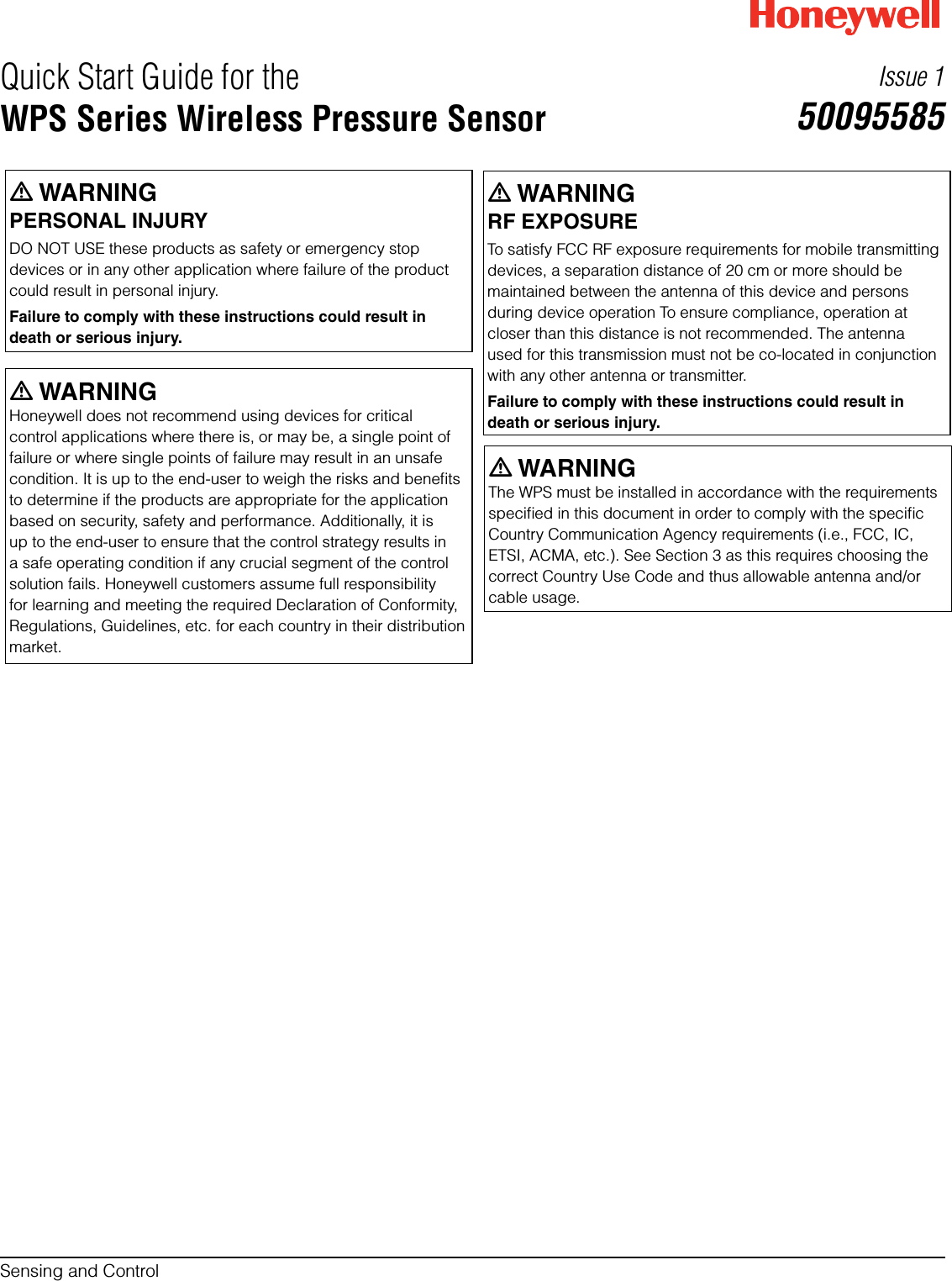


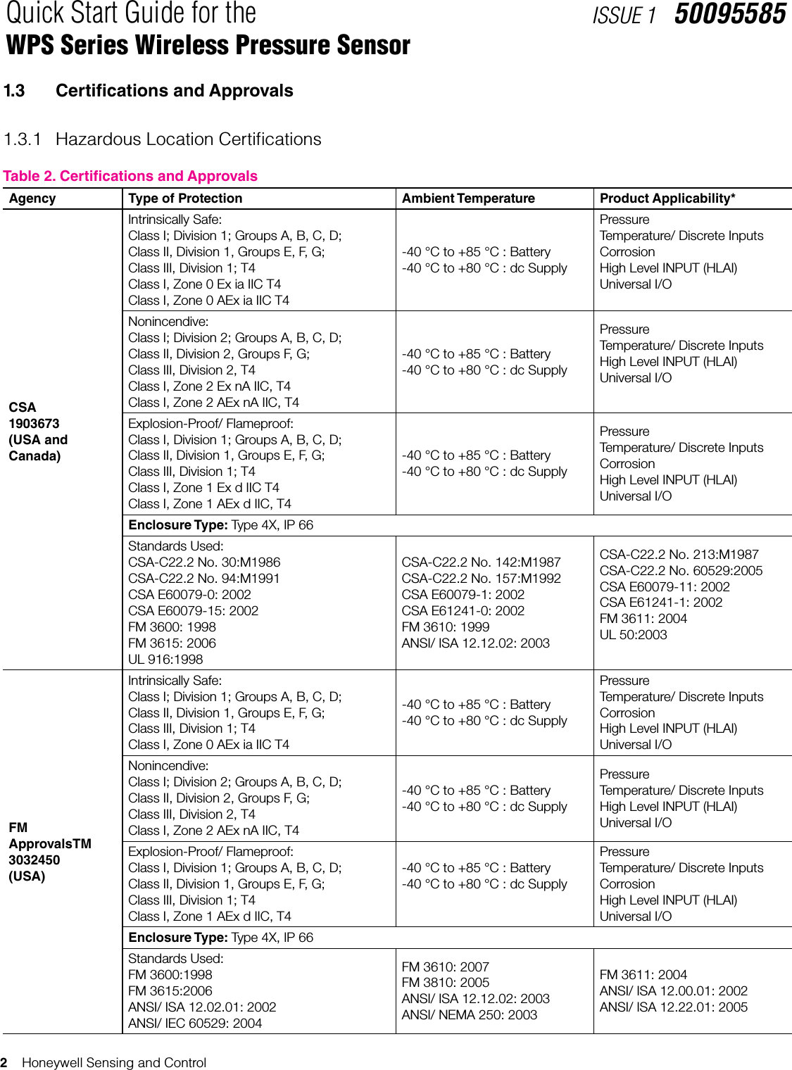
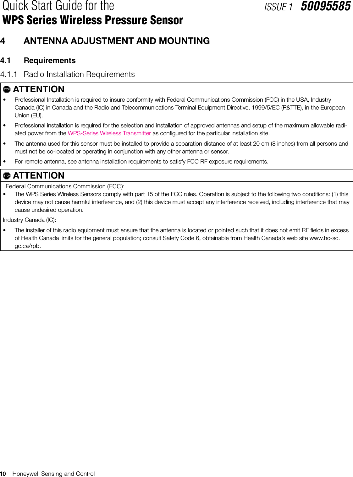
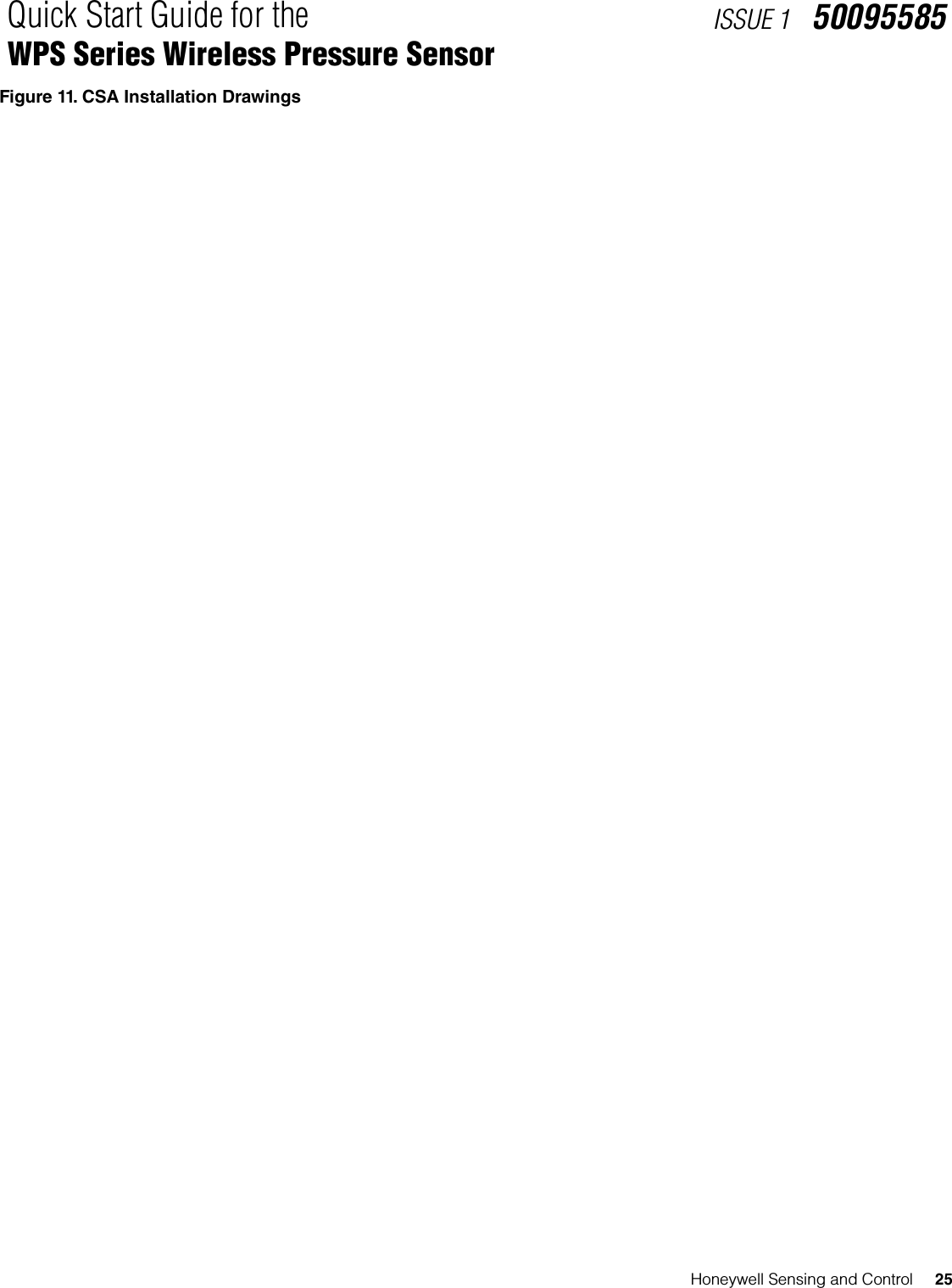
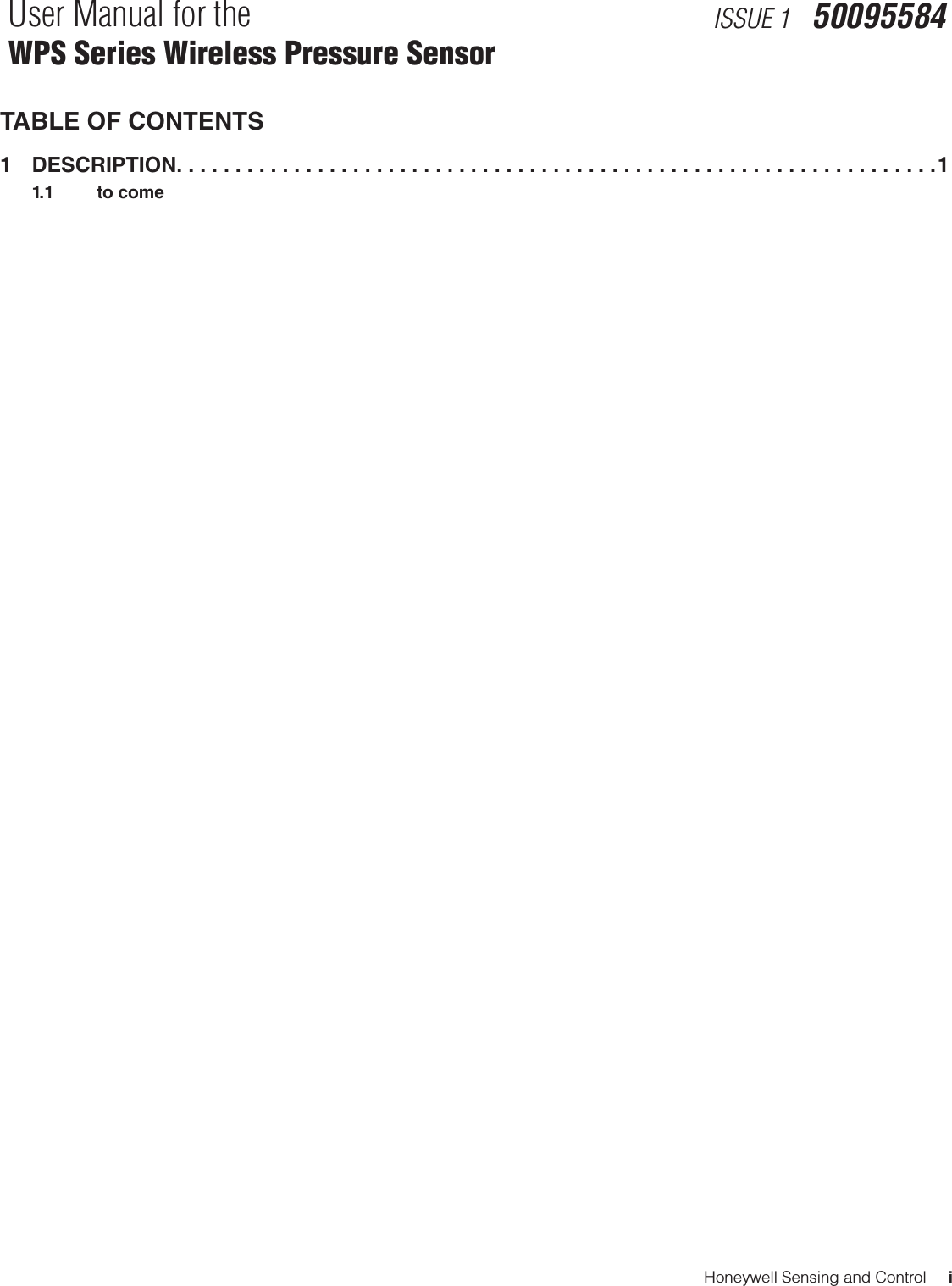
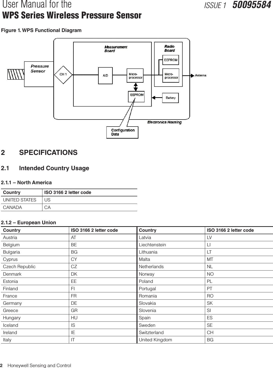
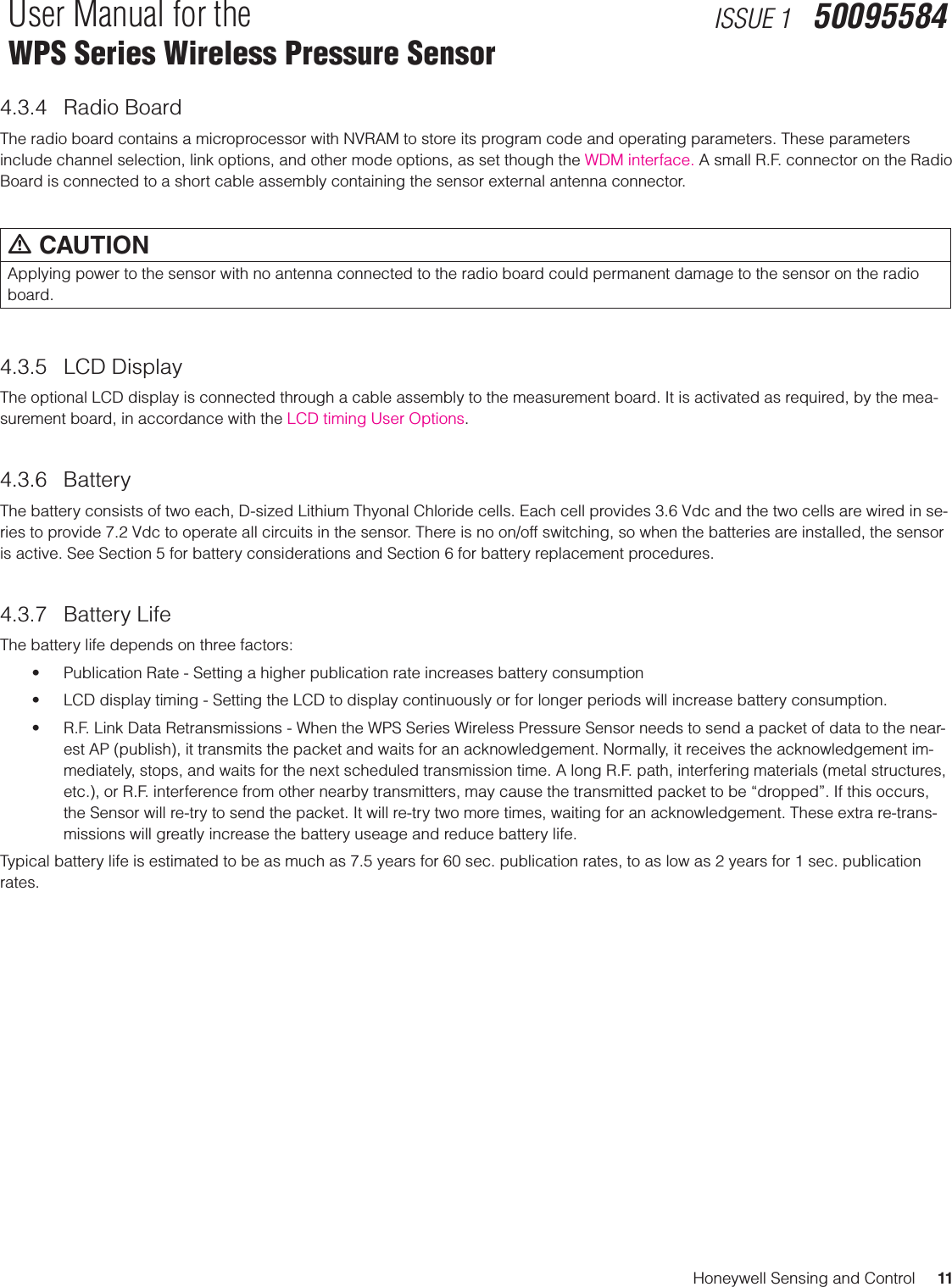
![Honeywell Sensing and Control 3Quick Start Guide for the WPS Series Wireless Pressure SensorISSUE 1 50095585Agency Type of Protection Ambient Temperature Product Applicability*ATEX- KEMA08ATEX0062XIntrinsically Safe:II 1 G Ex ia IIB T4II 1 D Ex tD A20 IP66 T90 oC-40 °C to +70 °C: Battery-40 °C to +80 °C : dc SupplyPressureTemperature/ Discrete InputsCorrosionHigh Level INPUT (HLAI)Universal I/OFlameproof:II 2 G Ex d [ia] IIB T4II 2 D Ex tD A21 IP66 T90 oC-40 °C to +70 °C: Battery-40 °C to +80 °C : dc SupplyPressureCorrosionHigh Level INPUT (HLAI)Universal I/OEnclosure: IP66Standards Used:EN 60079-0 : 2006EN 60079-26 : 2007EN 60079-1 : 2004EN 61241-0 : 2006EN 60079-11 : 2007EN 61241-1 : 2004ATEX- DEKRA08ATEX0074Nonincendive:II 3 G Ex nA [nL] IIC T4II 3 D Ex tD A22 IP66 T90 oC-40 °C to +84 °CPressureTemperature/ Discrete InputsCorrosionHigh Level INPUT (HLAI)Universal I/OEnclosure: IP66Standards Used:EN 60079-0 : 2006EN 61241-1 : 2004EN 60079-15 : 2005 EN 61241-0 : 2006IECEx- CSA09.0001XIntrinsically Safe:Ex ia IIB T4Ex tD A20 IP66 T90 oC-40 °C to +70 oC: Battery-40 °C to +80 °C : dc SupplyPressureTemperature/ Discrete InputsCorrosionHigh Level INPUT (HLAI)Universal I/OFlameproof:Ex d [ia] IIB T4Ex tD A21 IP66 T90 oC-40 °C to +70 °C: Battery-40 °C to +80 °C : dc SupplyPressureCorrosionHigh Level INPUT (HLAI)Universal I/ONonincendive:Ex nA [nL] IIC T4Ex tD A22 IP66 T90 oC-40 °C to +84 °C: Battery-40 °C to +80 °C : dc SupplyPressureTemperature/ Discrete InputsCorrosionHigh Level INPUT (HLAI)Universal I/OEnclosure: IP66Standards Used:IEC 60079-0 : 2004IEC 60079-26 : 2007IEC 60079-15 : 2001IEC 60079-1 : 2003IEC 61241-0 : 1999IEC 60079-11 : 1999IEC 61241-1 : 1999*See individual product manuals as dened on page iii for exact Models ** At time of printing, certication was pending.](https://usermanual.wiki/Honeywell-Sensing-and-Control/WPS001/User-Guide-2340389-Page-9.png)
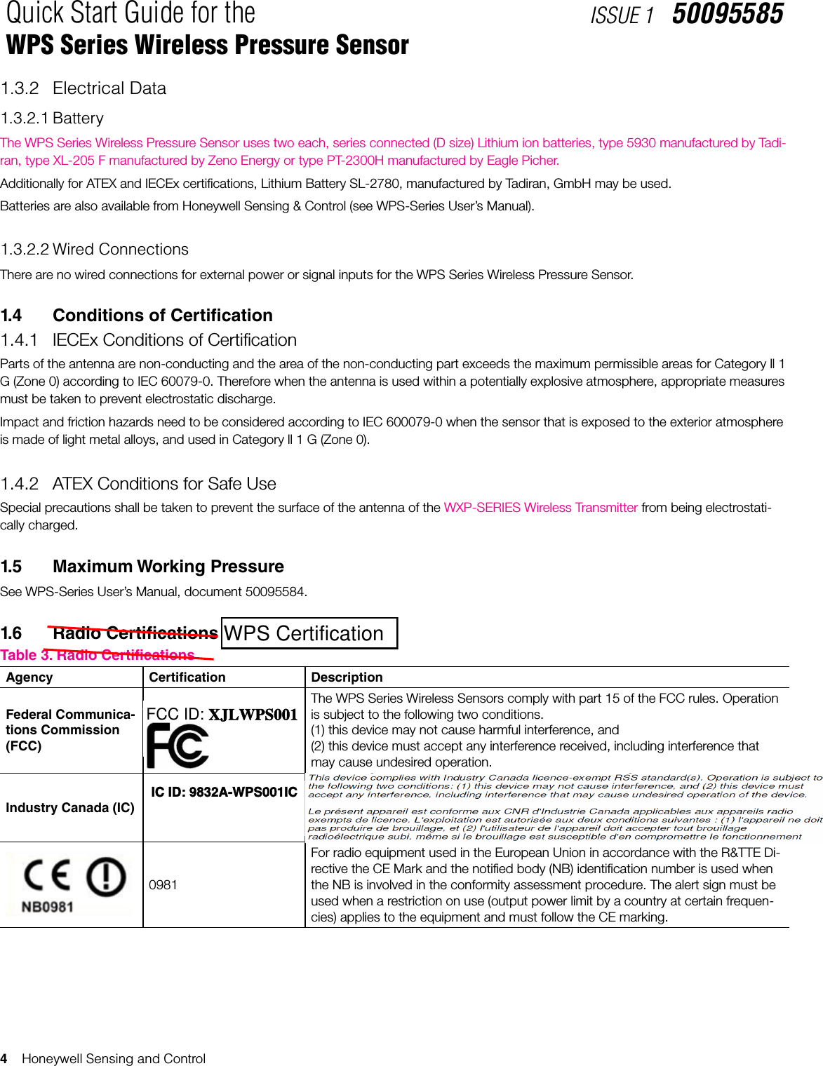
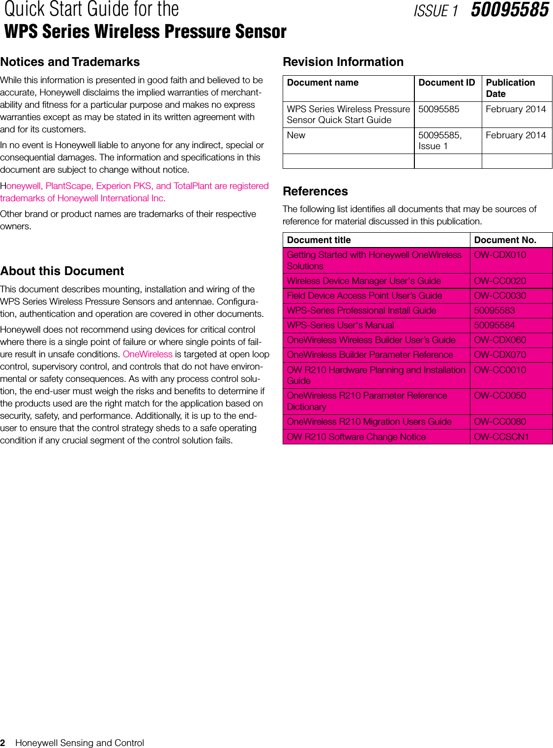
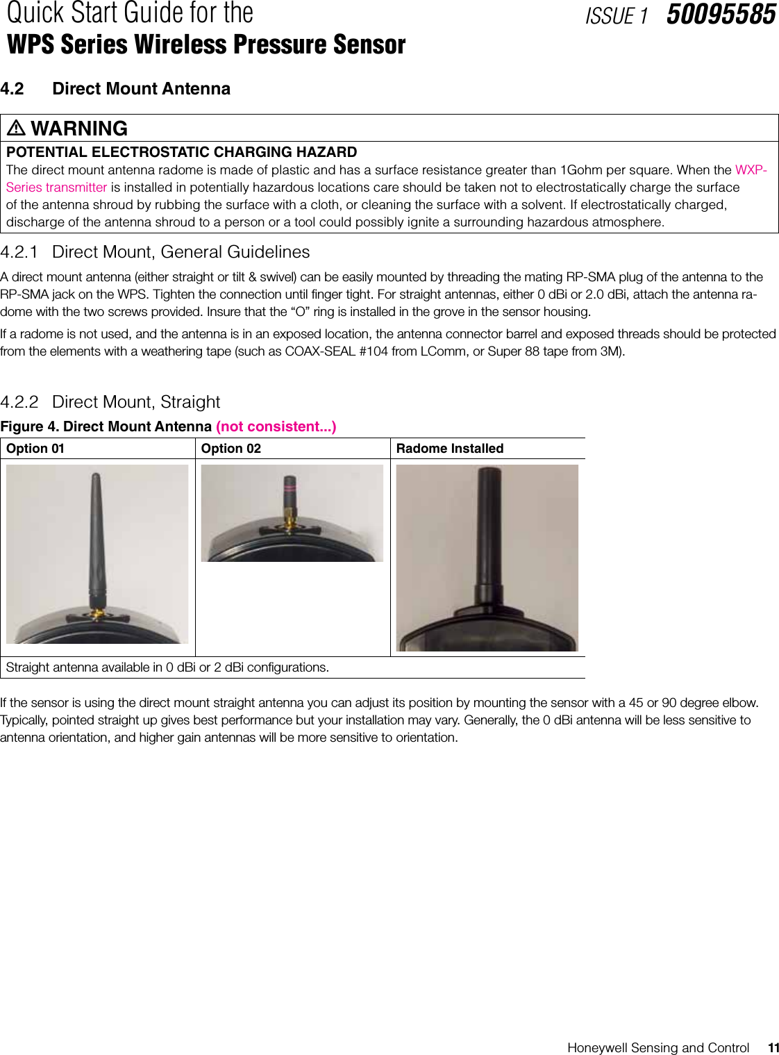
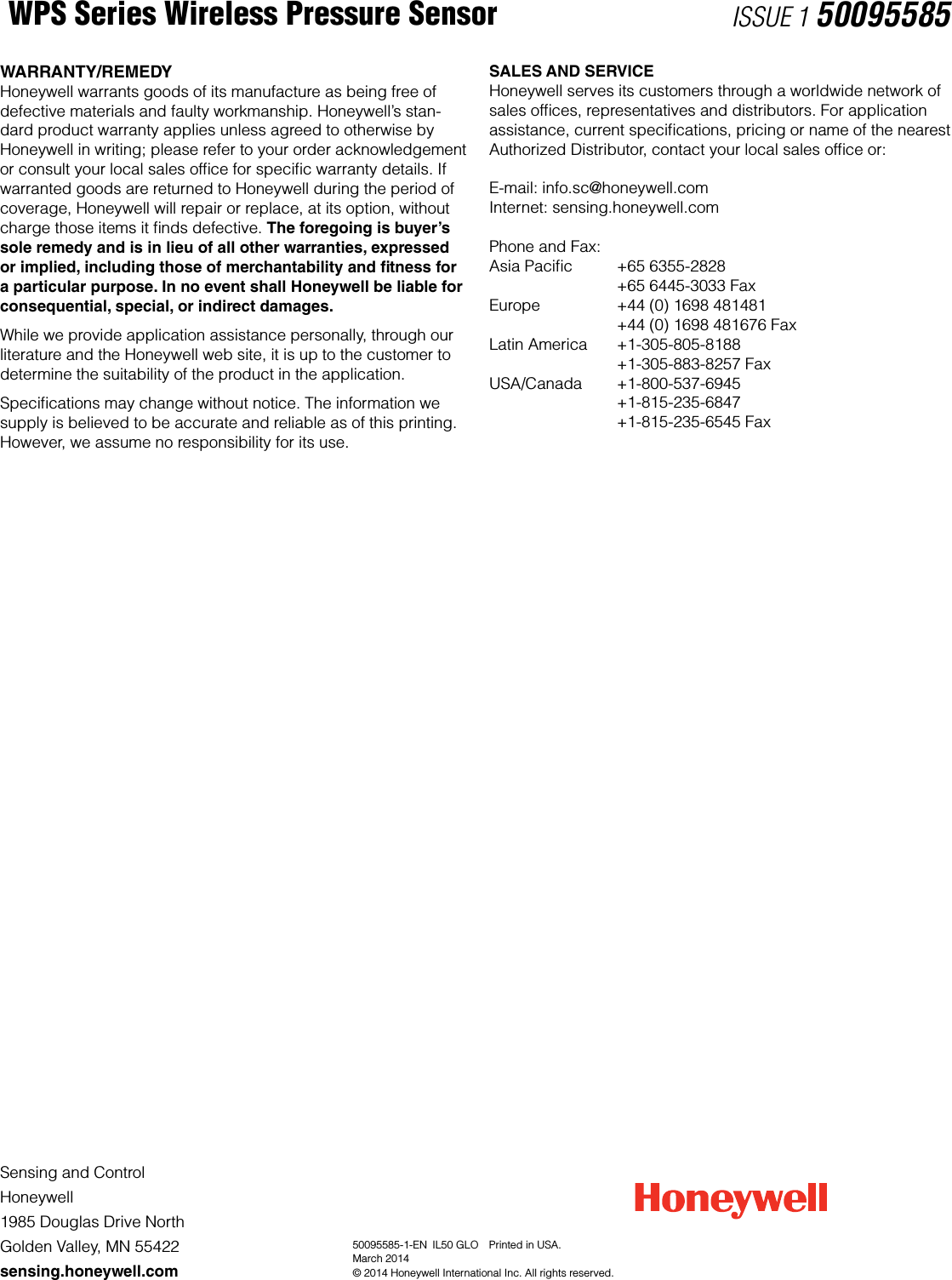
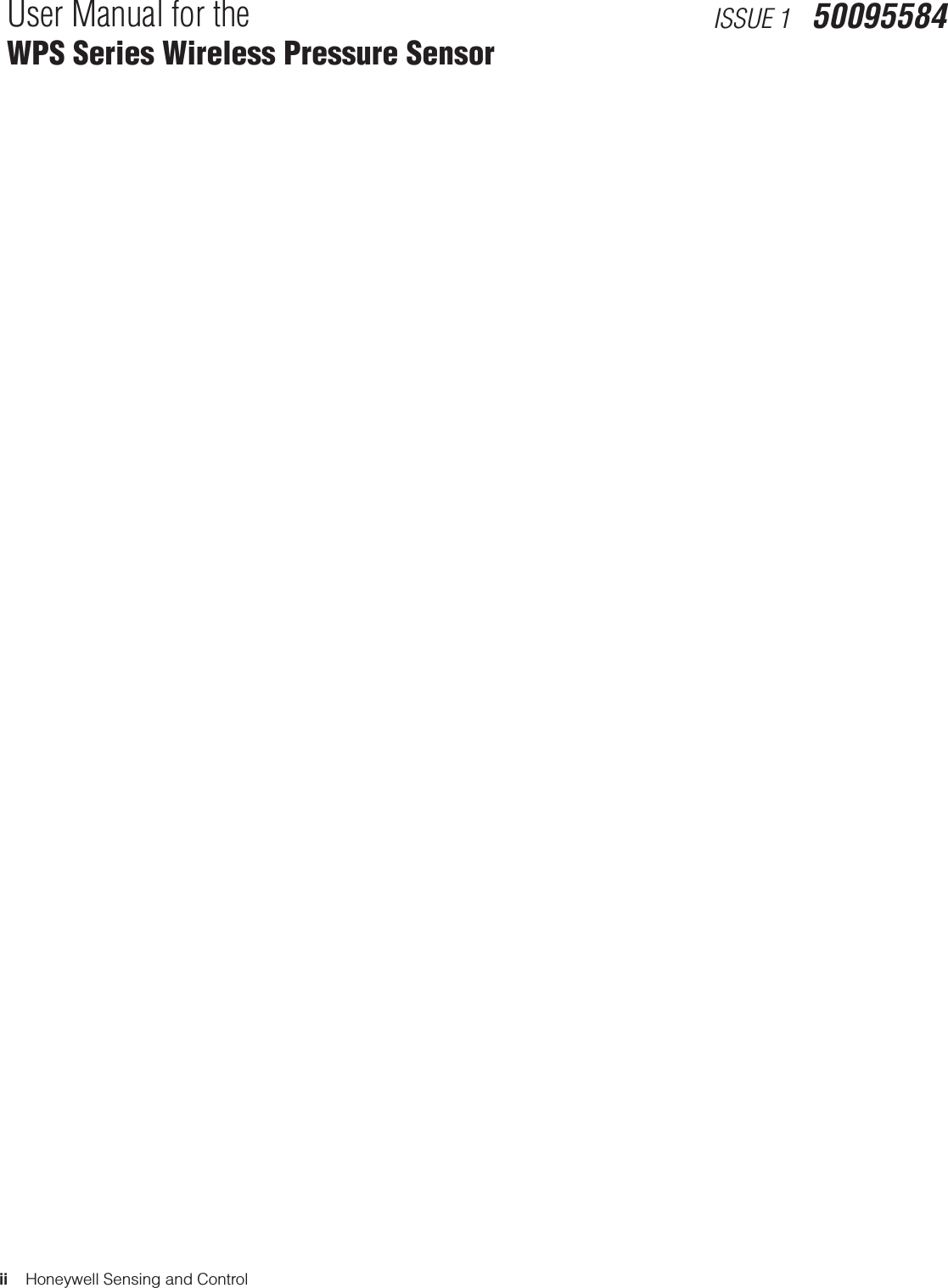
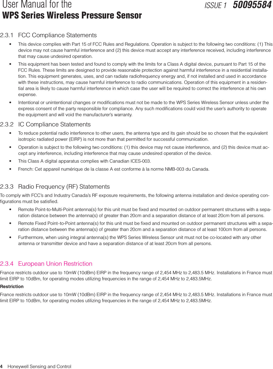
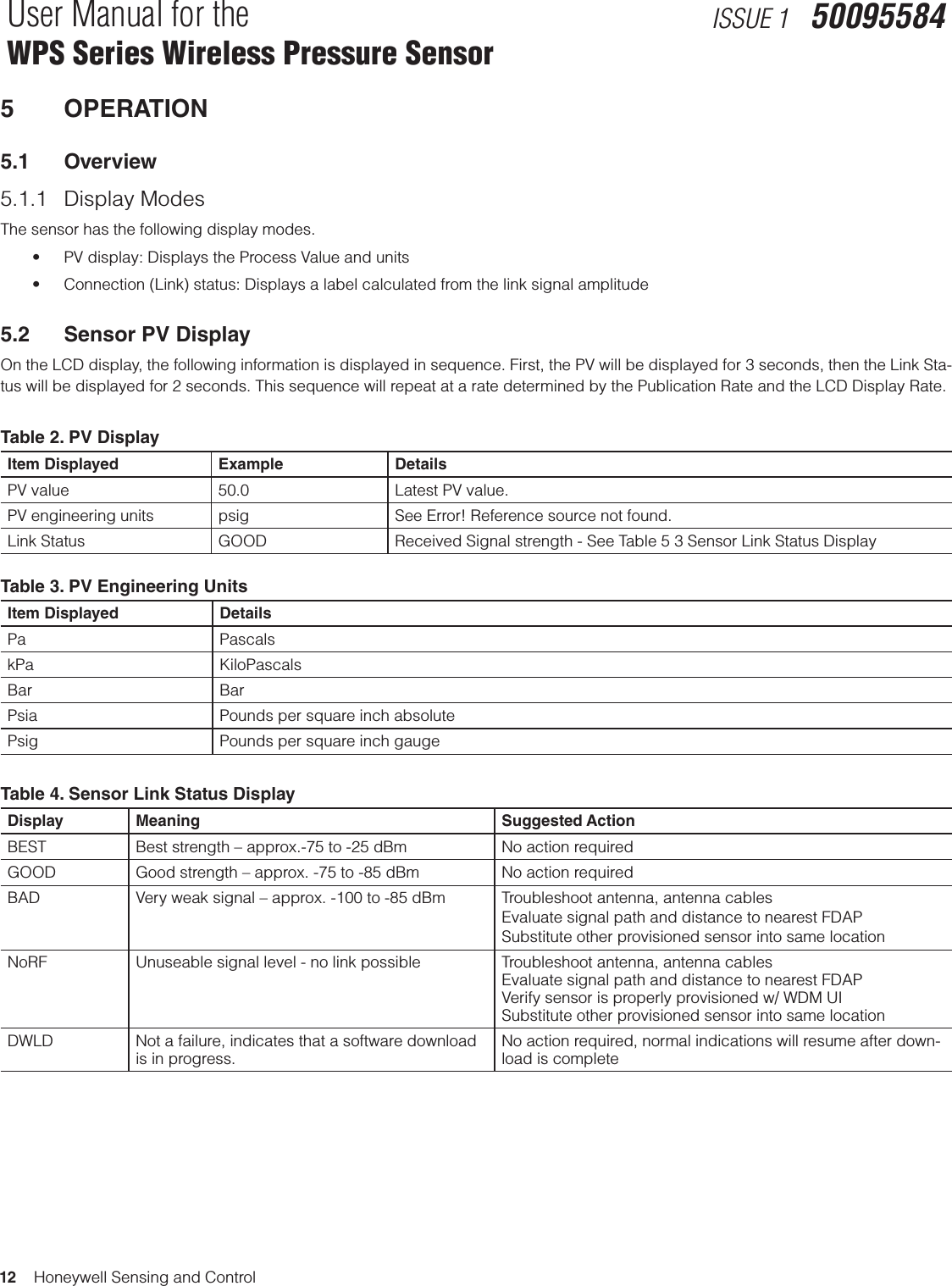
![6 Honeywell Sensing and ControlQuick Start Guide for theWPS Series Wireless Pressure SensorISSUE 1 500955852 SENSOR MOUNTING2.1 WeightModel WeightWPS-Series 2 lb., 3 oz. (1.0 kg)2.2 DimensionsFigure 1. Dimensions of WPS Series Wireless Pressure Sensor234 mm ±1 mm[9.21 in ±0.04 in]149 mm ±1 mm[5.87 in ±0.04 in]99 mm ±1 mm[3.9 in ±0.04 in] 95 mm ±1 mm[3.74 in ±0.04 in]45 mm [1.77 in]across at 31,75 mm [1.25 in]hex](https://usermanual.wiki/Honeywell-Sensing-and-Control/WPS001/User-Guide-2340389-Page-12.png)
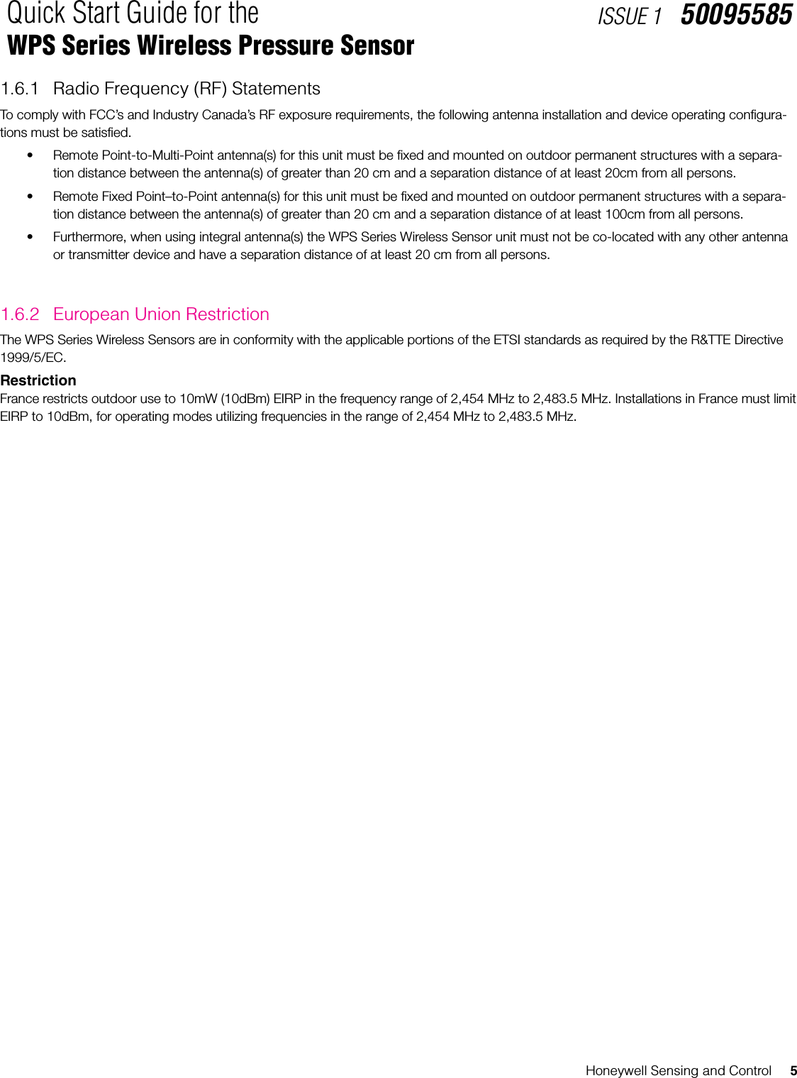
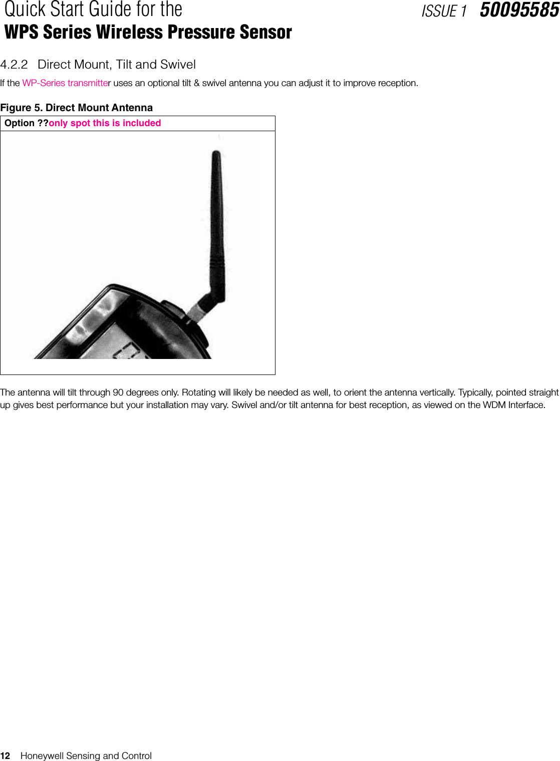
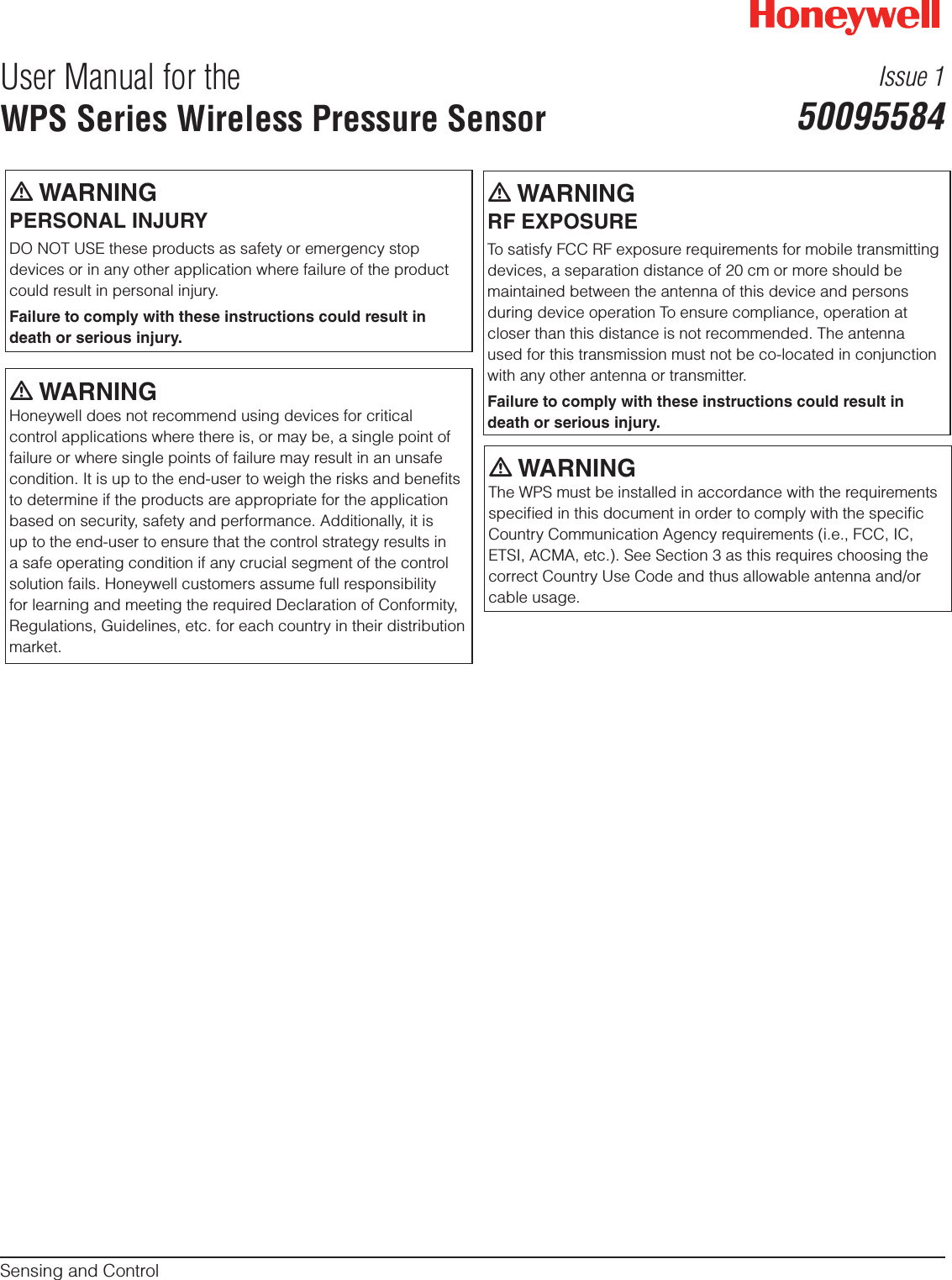
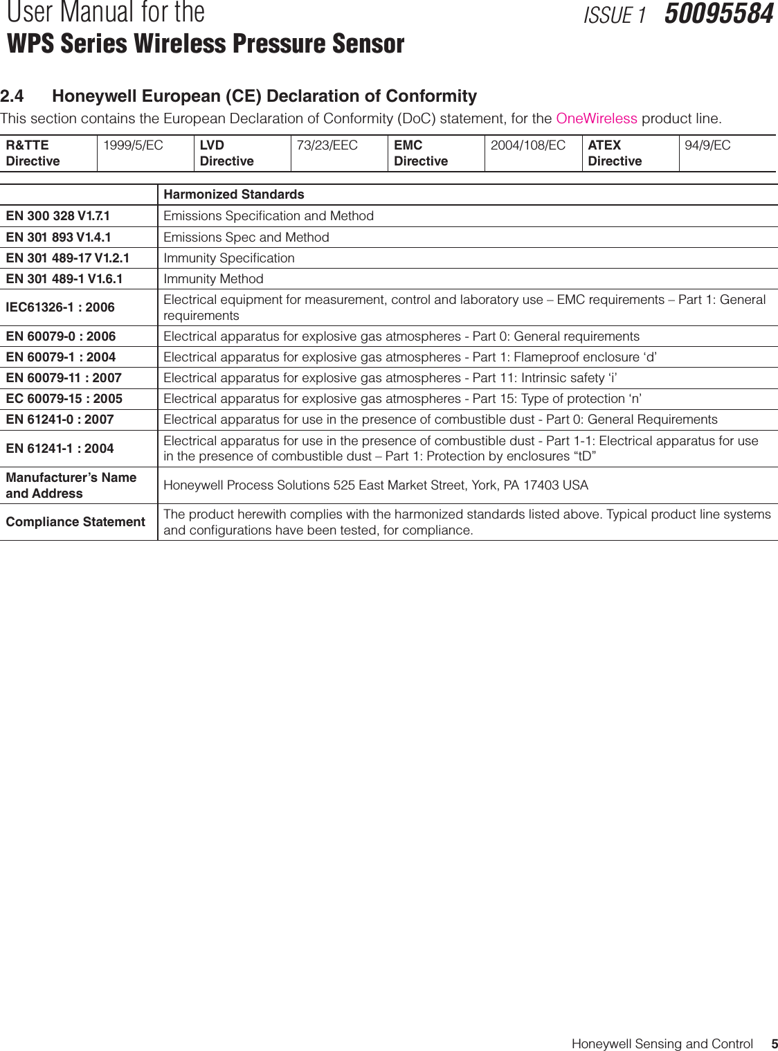
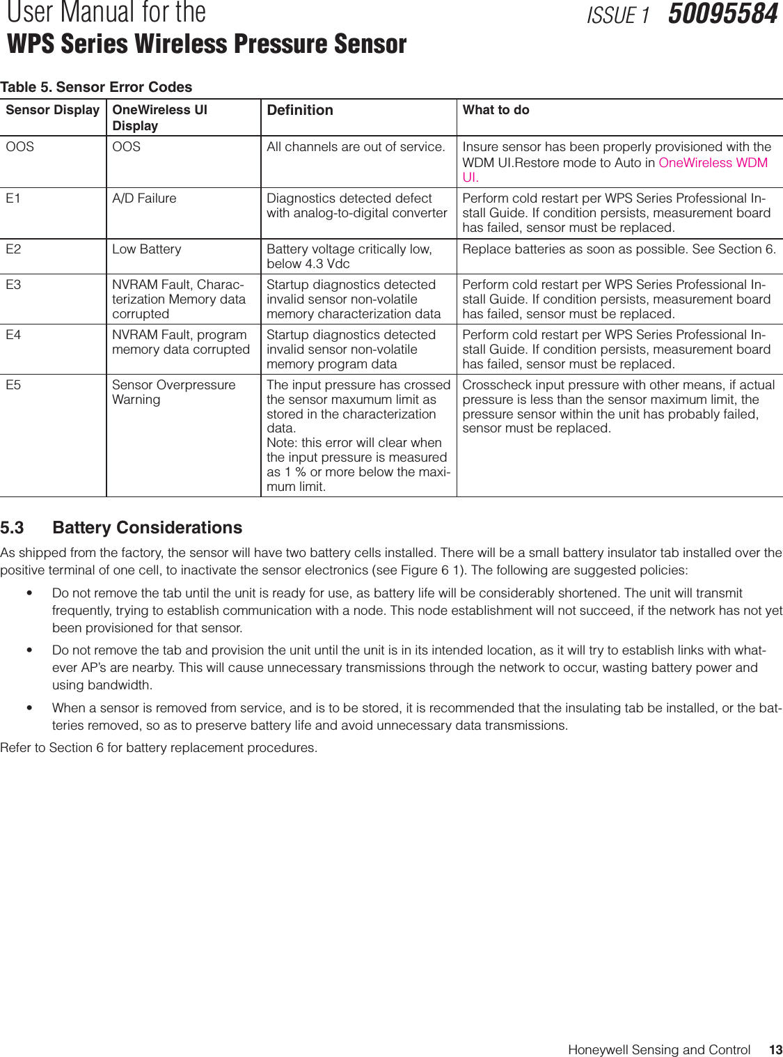
![8 Honeywell Sensing and ControlQuick Start Guide for theWPS Series Wireless Pressure SensorISSUE 1 50095585Figure 2. Typical Arrangement for 1/2 NPT Process Connection Piping, ATTENTIONFor liquid or steam, the piping should slope a minimum of 25,4 mm [1 in] per 305 mm [1 ft]. Slope the piping down towards the sensor if the sensor is below the process connection so the bubbles may rise back into the piping through the liquid. If the sensor is located above the process connection, the piping should rise vertically above the sensor; then slope down towards the flowline with a vent valve at the high point. For gas measurement, use a condensate leg and drain at the low point (freeze protection may be required here).m CAUTIONProperty damage may result if operating temperature limits of sensor are exceeded. Sensor housing must not exceed 85 °C [185 °F]. To reduce the temperature of the process that comes into contact with the sensor meter body, install impulse piping. As a general rule there is a 56 °C drop [100 °F] in the temperature of the process for every foot (305 mm) of ½ inch uninsulated piping.3.1.2 Process ConnectionsTable 5. Process ConnectionsSensor Type Process ConnectionGage Process head with 1/2 inch NPT male and 1/4” NPT female connectionThread adapter with 3/4” NPT male and 1/2” female connections is optionalAbsolute Process head with 1/2 inch NPT male and 1/4” NPT female connectionThread adapter with 3/4” NPT male and 1/2” female connections is optional](https://usermanual.wiki/Honeywell-Sensing-and-Control/WPS001/User-Guide-2340389-Page-14.png)
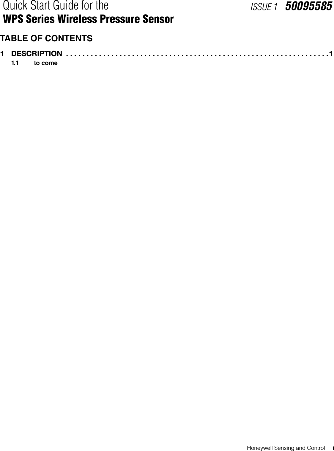
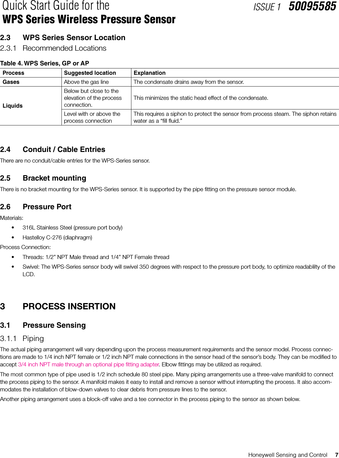
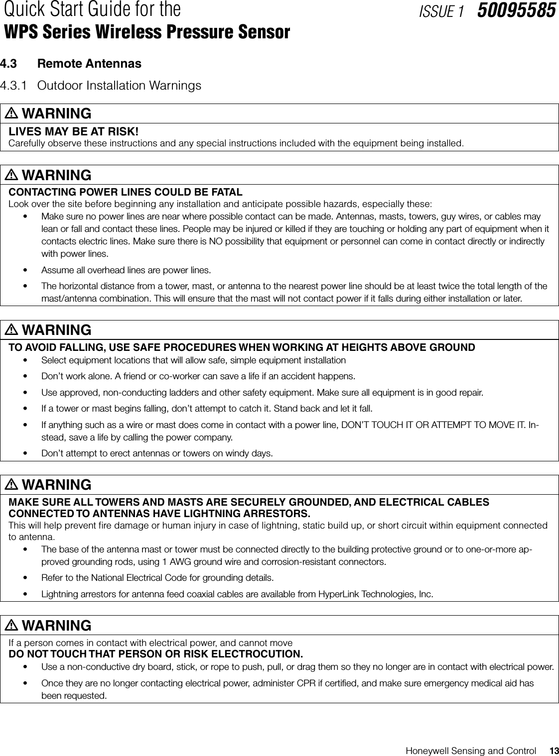
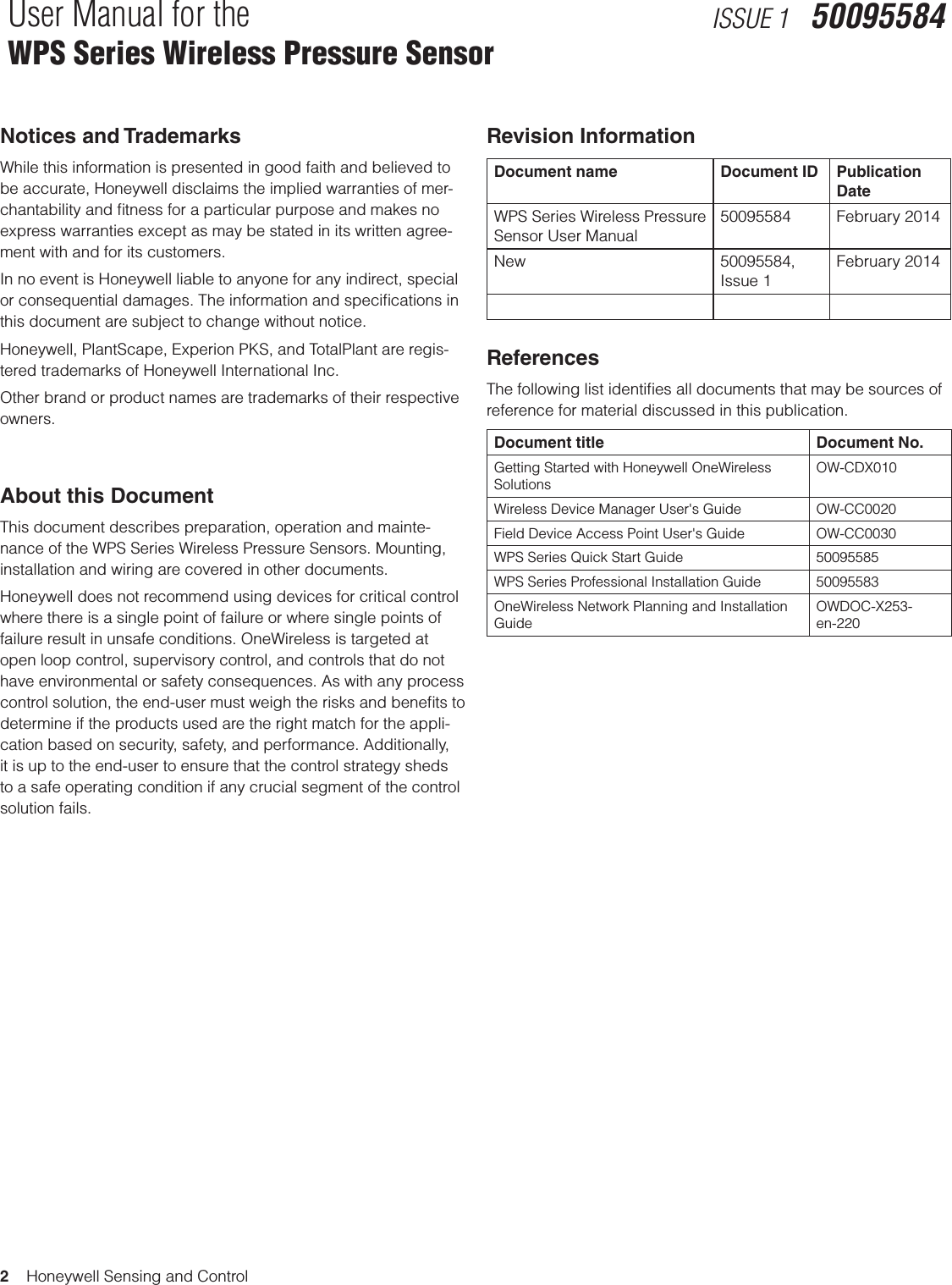
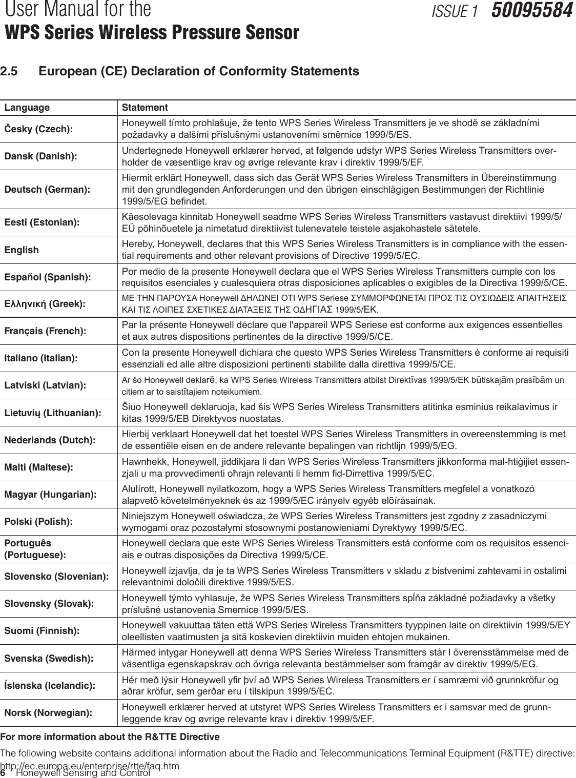
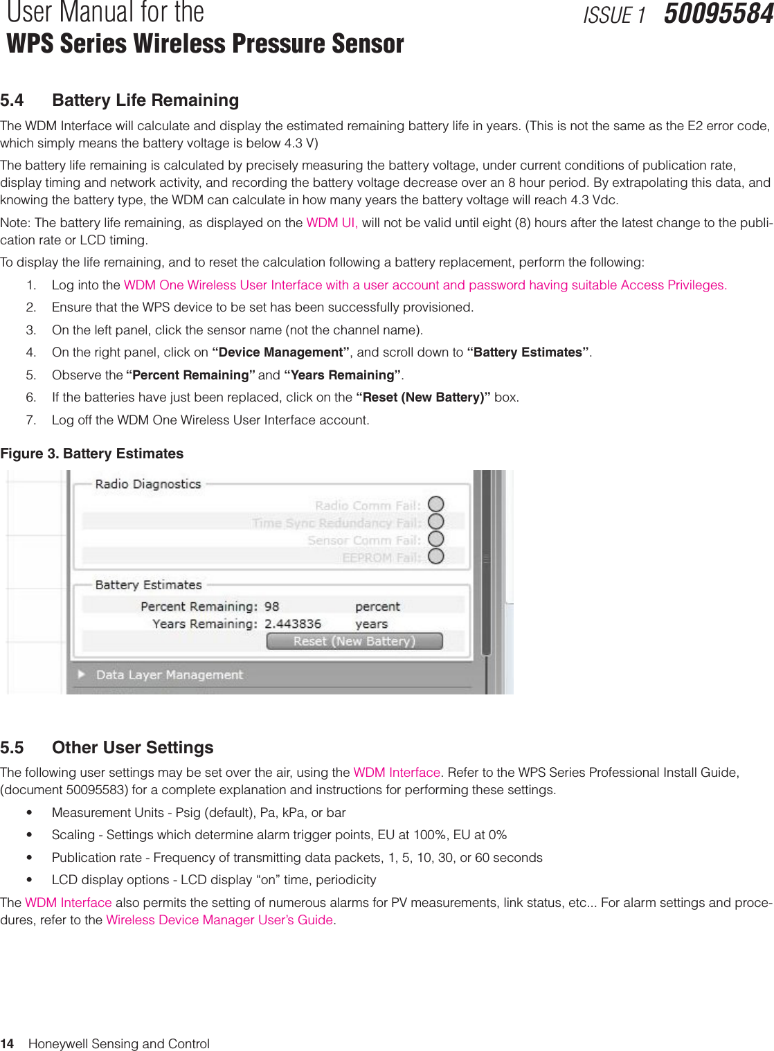
![Honeywell Sensing and Control 9Quick Start Guide for the WPS Series Wireless Pressure SensorISSUE 1 50095585Figure 3. Process Connection - Pipe Fitting3.1.3 General piping guidelinesWhen measuring uids containing suspended solids, install permanent valves at regular intervals to blow-down piping. Blow-down all lines on new installations with compressed air or steam and ush them with process uids (where possible) before connect-ing these lines to the sensor’s meter body. Be sure all the valves in the blow-down lines are closed tight after the initial blow-down procedure and each maintenance procedure after that.Mount sensor vertically to assure best accuracy, and to obtain optimum R.F. link performance. Position the spirit balance on pressure con-nection surface of Sensor body.3.1.4 Sensor Housing SwivelingThe WPS Series sensor housing will swivel through a 350 degree range to facilitate easy reading of the LCD display. To adjust the swivel mounting:1. Insure that the process connector (threaded tting) is in its nal position and is fully tightened, using a wrench on the hex-nut area above the threads (do NOT tighten using the sensor body).2. Loosen the large nut just below the housing using a 1 3/4” wrench.3. Swivel sensor housing as needed.4. While holding the sensor body in place, gently tighten the large nut with a 1 3/4” wrench to 7 Nm [5.2 ft-lb].](https://usermanual.wiki/Honeywell-Sensing-and-Control/WPS001/User-Guide-2340389-Page-15.png)
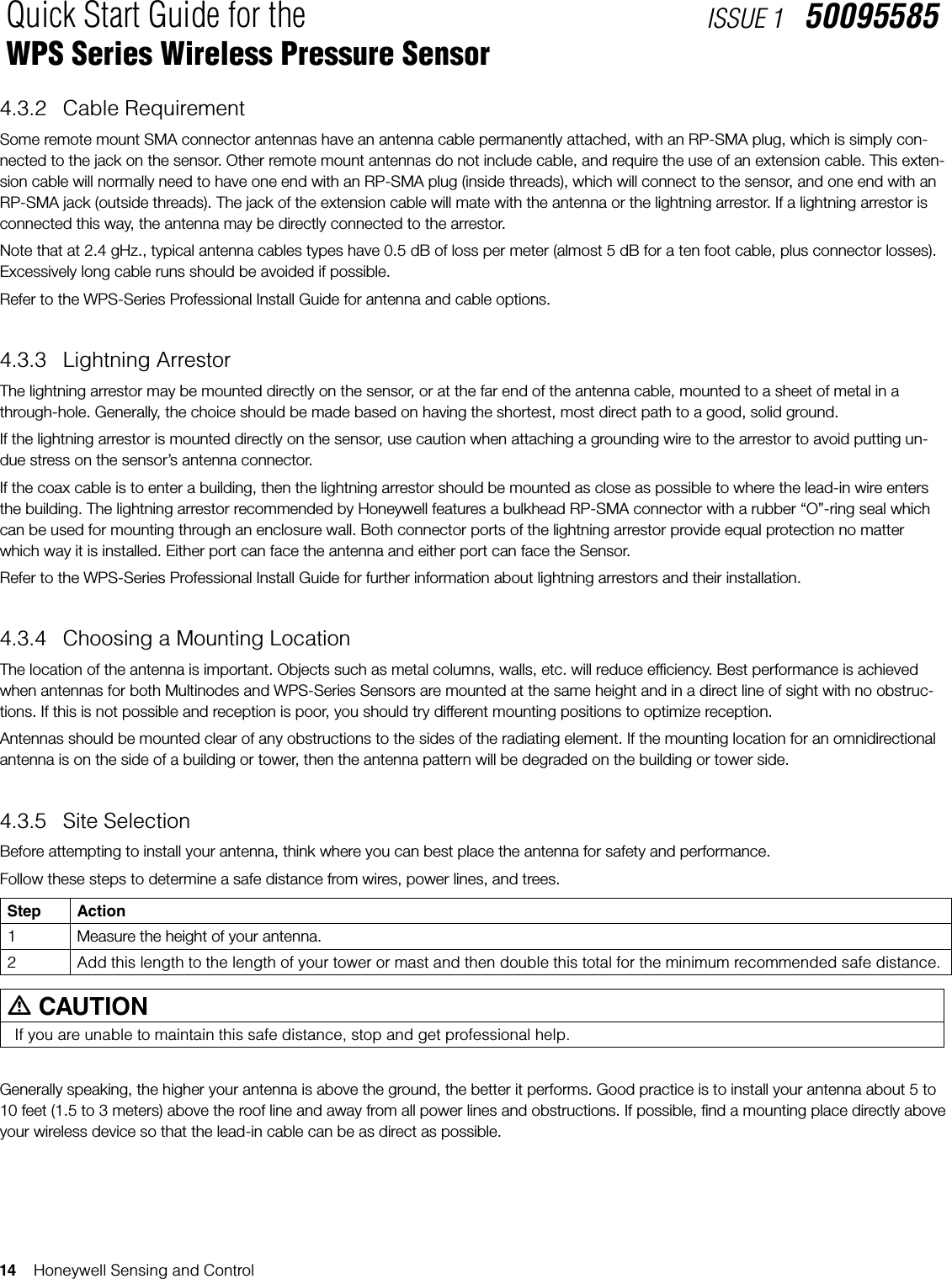
![Honeywell Sensing and Control 17Quick Start Guide for the WPS Series Wireless Pressure SensorISSUE 1 500955854.3.9 Mast MountingMast mounting kits consist of a mounting bracket and one or two U-bolt clamps. These kits allow you to mount the bracket to masts with outside diameters (O.D.) from 3,2 cm [1.25 in] to 5,1 cm [2 in]. Honeywell recommends that a 3,8 cm [1.5 in] or larger tubing mast be used. The antenna is then mounted in a hole on the bracket upper surface. Most standard brackets will have a hole too large for an SMA mount antenna, so a new hole will be needed. For hole dimensions, refer to to the WPS-Series Professional Install Guide.Follow these steps to mount the antenna on a mast.Step Action1Assemble your new antenna on the ground at the installation site. For SMA mount antennas, mount the RP-SMA jack of the an-tenna cable to a hole in the bracket, using the nut and lockwasher supplied. For lightning arrestor mounting, mount the lightning arrestor in the mounting bracket hole, and attach the extension cable to the arrestor.2Screw the SMA antenna onto the cable or lightning arrestor. Tighten all cables by hand only; do not use tools or you could overtighten. Make sure that the connections are sealed (if outdoors) the prevent moisture and other weathering elements from effecting performance. Honeywell recommends using a weathering tape (such as COAX-SEAL #104 from LComm, or Super 88 tape from 3M) for outdoor connections. Silicon sealant or ordinary electrical tape is not recommended for sealing out door con-nections.3 Attach the antenna bracket to the mast, using the U-Bolts as required.4 Using tie-wraps (cable ties), secure the coax cable to the mast, using a tie-wrap every ten to twelve inches (25 to 30 cm).5 Follow standard strain relief practice when installing the antenna cable. Avoid excessive strain, bending, kinks, or crushing (stepping on or placing any weight on cable) before, during or after the coax cable is secured in its final position.6Make sure the mast does not fall the “wrong way” should you lose control as you raise or take down the mast. Use a durable non-conductive rope. Have an assistant tend to the rope; ready to pull the mast clear of any hazards (such as power lines) should it begin to fall.7If the installation will use guy wires: • Install guy anchor bolts. • Estimate the length of guy wire and cut it before raising the mast. • Attach guy wires to a mast using guy rings.8Carefully connect the antenna and mast assembly to its mounting bracket and tighten the clamp bolts. In the case of a guyed installation, you must have at least one assistant to hold the mast upright while the guy wires are at-tached and tightened to the anchor bolts.9Attach a "DANGER" label at eye level on the mast.10 Install ground rods to remove any static electricity buildup and connect a ground wire to the mast and ground rod. Use ground rods designed for that purpose; do not use a spare piece of pipe.11 When attaching the coax cable to the WXP-Series, it is recommended that a drip loop with a radius of at least 12 inches (30 cm) be formed close to the WXP-Series. This will minimize ice and water buildup on the sensor itself. Tighten cables by hand only; do not use tools or you could overtighten.](https://usermanual.wiki/Honeywell-Sensing-and-Control/WPS001/User-Guide-2340389-Page-23.png)
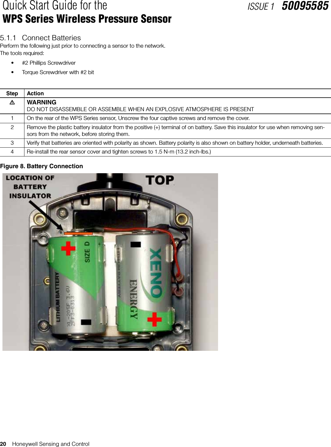
![Honeywell Sensing and Control 19Quick Start Guide for the WPS Series Wireless Pressure SensorISSUE 1 500955855 START UP5.1 Battery ConnectionAs shipped, the WPS Series Wireless Pressure Sensor contains two each, D-sized batteries, held in a battery holder. The batteries are kept in a disconnected state by a small plastic battery insulator. This insulator must be removed prior to provisioning and operating the sensor.Suggested policies for battery connection are:• Do not remove the tab until the unit is ready for use, as battery life will be considerably shortened. The unit will transmit frequently, trying to establish communication with a node. This node establishment will not succeed, if the network has not yet been provi-sioned for that sensor. • Do not remove the tab and provision the unit until the unit is in its intended location, as it will try to establish links with whatever AP’s are nearby. This will cause unnecessary transmissions through the network to occur, wasting battery power and using band-width.• When a sensor is removed from service, and is to be stored, it is recommended that the insulating tab be installed, or the batteries removed, so as to preserve battery life and avoid unnecessary data transmissions. m WARNINGS• Risk of death or serious injury by explosion. Do not open sensor enclosure when an explosive gas atmosphere is present. • Batteries must not be changed in an explosive gas atmosphere.• The sensor enclosure must not be opened when an explosive gas atmosphere is present.• When not in use the batteries must be stored in a non-hazardous area• The batteries used in this device may present a risk of re or chemical burn if mistreated. Do not recharge, disassemble, heat above 100 °C [212 °F], or incinerate. Do not expose batteries to water.• When installing batteries do not snag the battery terminal on the clip or the battery may be damaged. Do not apply excessive force.• Do not drop. Dropping the battery may cause damage. If a battery is dropped, do not install the dropped battery into the sen-sor. Dispose of dropped battery promptly per local regulations or per the battery manufacturer’s recommendations., ATTENTIONBoth batteries must be the same model from the same manufacturer. Mixing old and new batteries or different manufacturers is not permitted.Use only the following 3.6V lithium thionyl chloride (Li-SOCl2) batteries (non-rechargeable), size D. No other batteries are ap-proved for use in WXP-Series Wireless Transmitters.• Xeno Energy XL-205F• Tadiran TL-5930/s• Honeywell p/n WBT5 (Two 3.6V lithium thionyl chloride batteries)](https://usermanual.wiki/Honeywell-Sensing-and-Control/WPS001/User-Guide-2340389-Page-25.png)


![Honeywell Sensing and Control 3User Manual for the WPS Series Wireless Pressure SensorISSUE 1 500955842.2 Certications and Approvals 2.2.1 SensorSee the product label for applicable approvals and ratingsApproval/Item Ratings/DescriptionCSAcus Intrinsically Safe CL I, Div 1, Groups A, B, C, & D; CL II, Div 1, Groups E, F & G; CL III, T4CL I, Zone 0: Ex ia IIC, T4; CL I, Zone 0: AEx ia IIC, T4CSAcus Explosionproof CL I, Div 1, Groups A, B, C, & D; CL II, Div 1, Groups E, F & G; CL III, T4CL I, Zone 1: Ex d IIC, T4; CL I, Zone 1: AEx d IIC, T4CSAcus Nonincendive CL I, Div 2, Groups A, B, C & D; CL II, Div 2, Groups F & G; CL III, Div 2, T4CL I, Zone 2: Ex nA IIC, T4; CL I, Zone 2: AEx nA IIC, T4FM Approvals Intrinsically Safe CL I, Div 1, Groups A, B, C, & D; CL II, Div 1, Groups E, F & G; CL III, T4CL I, Zone 0: AEx ia IIC, T4FM Approvals Explosionproof CL I, Div 1, Groups A, B, C, & D; CL II, Div 1, Groups E, F & G; CL III, T4CL I, Zone 1: AEx d IIC, T4FM Approvals Nonincendive CL I, Div 2, Groups A, B, C & D; CL II, Div 2, Groups F & G; CL III, Div 2, T4CL I, Zone 2: AEx nA IIC, T4KEMA 08 ATEX0062X Intrinsically Safe Flameproof KEMA 08 ATEX0074Non-SparkingEX II 1 GD: Ex ia IIB; T4 Ta = 70ºC; Ex tD A20 IP66 T90ºCEX II 2 GD: Ex d [ia] IIB; T4 Ta = 70ºC; Ex tD A21 IP66 T90ºCEX II 3 GD: Ex nA [nL] IIC; T4 Ta = 84ºC; Ex tD A22 IP66 T90ºCIECEx CSA 09.0001X Intrinsically Safe Flameproof Non-SparkingEx ia IIB; T4 Ta = 70ºC; DIP A20 IP66 T90ºCEx d [ia] IIB; T4 Ta = 70ºC; DIP A21 IP66 T90ºCEx nA [nL] IIC; T4 Ta = 84ºC; DIP A22 IP66 T90ºCProcess Connections inDivision 2 / Zone 2 mDivision 2 / Zone 2 apparatus may only be connected to processes classified as non-hazardous or Division 2 / Zone 2. Connection to hazardous (flammable or ignition capable) Division 1 / Zone 0, or 1 process is not permitted.Enclosure Type Type 4X, IP 66Class II and III installations and Type 4X/IP66 applications require that all cable and unused entries be sealed with a NRTL (National Recognized Testing Laboratory) listed cable gland or conduit plug. Cable glands and conduit plugs are not supplied with the prod-uct.2.2.2 Provisioning DeviceProvisioning the WPS Series Wireless Pressure Sensor is accomplished over the air, using the WDM Interface. A device description file (.DD), supplied with Sensor, is loaded into the WDM system as part of the provisioning process. Handheld infrared provisioning devices are not supported. 2.3 Agency Compliance InformationThis section contains the Federal Communications Commission (FCC), Industry Canada (IC) and Radio Frequency compliance state-ments for the Honeywell WPS Series Wireless Pressure Sensor. , ATTENTIONWPS Series units must be professionally installed in accordance with the requirements specified in the OneWireless WPS Series Agency Compliance Professional Installation Guide.](https://usermanual.wiki/Honeywell-Sensing-and-Control/WPS001/User-Guide-2340389-Page-41.png)
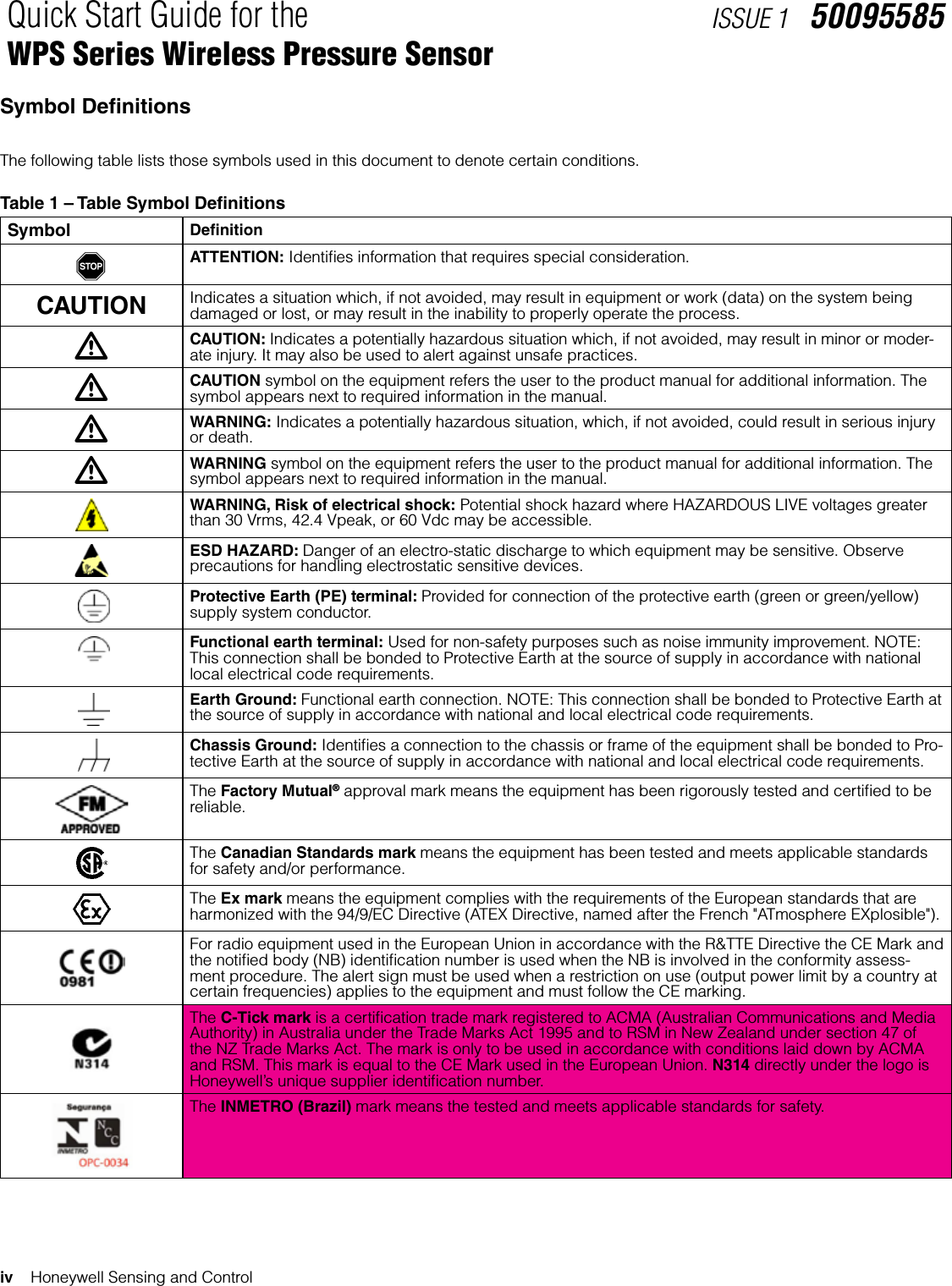
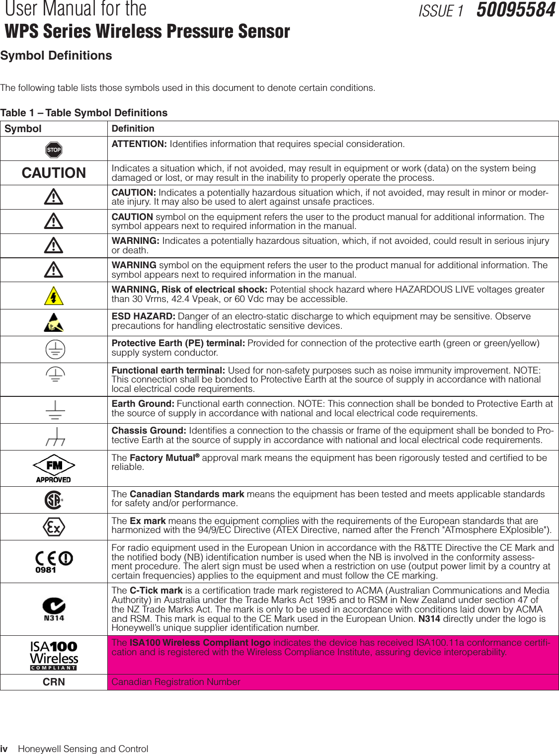
![16 Honeywell Sensing and ControlUser Manual for the WPS Series Wireless Pressure SensorISSUE 1 500955846.2.4 Tools required• #2 Phillips Screwdriver• Torque Screwdriver with #2 bit, ATTENTIONBatteries must be replaced only by a trained service technician.m WARNINGS• Risk of death or serious injury by explosion. Do not open sensor enclosure when an explosive gas atmosphere is present. • Batteries must not be changed in an explosive gas atmosphere.• The sensor enclosure must not be opened when an explosive gas atmosphere is present.• When not in use, the batteries must be stored in a non-hazardous area.• The batteries used in this device may present a risk of fire or chemical burn if mistreated. Do not recharge, disassemble, heat above 100 °C [212 °F], or incinerate. Do not expose batteries to water.• When installing batteries do not snag the battery terminal on the clip or the battery may be damaged. Do not apply exces-sive force.• Do not drop. Dropping the battery may cause damage. If a battery is dropped, do not install the dropped battery into the sensor. Dispose of dropped battery promptly per local regulations or per the battery manufacturer’s recommendations.Figure 4. Sensor Battery ReplacementShould we include warn-ing that batteries must be replaced at the same time?](https://usermanual.wiki/Honeywell-Sensing-and-Control/WPS001/User-Guide-2340389-Page-54.png)
![Honeywell Sensing and Control 17User Manual for the WPS Series Wireless Pressure SensorISSUE 1 50095584Table 7. Battery Replacement ProcedureStep ActionmWARNINGDO NOT DISASSEMBLE OR ASSEMBLE WHEN AN EXPLOSIVE ATMOSPHERE IS PRESENT1 On the rear of the WPS Series sensor, Unscrew the four captive screws and remove the cover.2 Using thumb and forefinger, carefully pry each battery out, lifting first one end, then the other.Caution! Do not scratch the battery outside covering on the sharp edges of the battery clips. Do not use sharp tools, knives or screwdrivers.3 Remove the old batteries and dispose of them promptly according to local regulations or the battery manufacturer’s rec-ommendations.4 Orient two new batteries with polarity as shown. Battery polarity is also shown on battery holder.Press two new batteries into the battery clips, starting on one end, then pressing in the other end.Caution! Do not scratch the battery outside covering on the sharp edges of the battery clips.5 Re-install the rear sensor cover and tighten screws to 1,5 Nm [13.2 in-lb].6 Reset battery life counter (see Section 5.4) using the WDM Interface.6.3 Replacing Antenna6.3.1 Tools required• #1 Phillips Screwdriver• Torque Screwdriver with #1 bit, ATTENTIONYou must replace your antenna with the same type and gain, that is, elbow, straight, or remote. Changing to a different antenna type is not permitted by approval agencies..m CAUTIONTake precautions against electrostatic discharge to prevent damaging the sensor module.](https://usermanual.wiki/Honeywell-Sensing-and-Control/WPS001/User-Guide-2340389-Page-55.png)
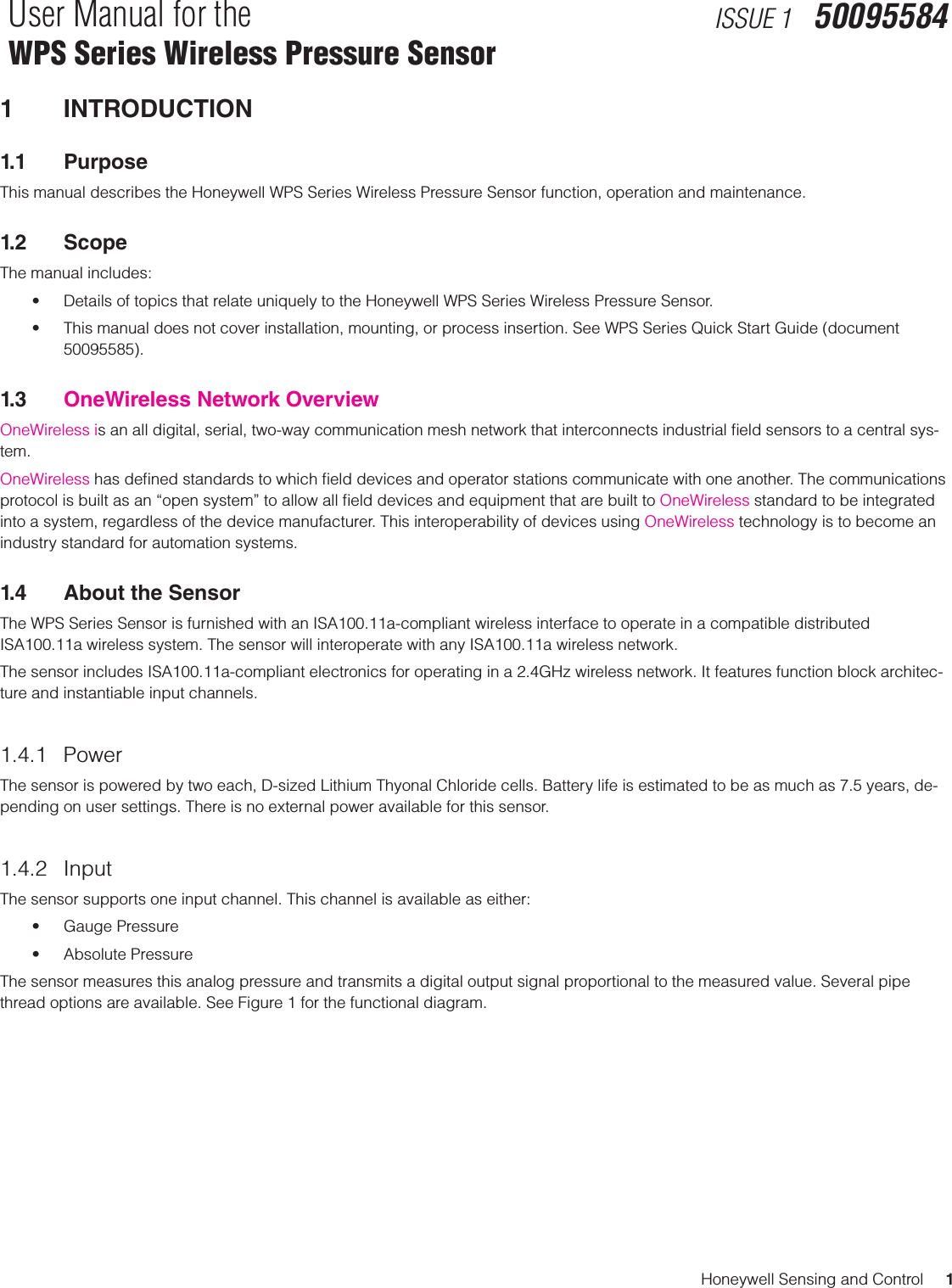
![18 Honeywell Sensing and ControlUser Manual for the WPS Series Wireless Pressure SensorISSUE 1 50095584Figure 5. Antenna ReplacementTable 8. Antenna Replacement ProcedureStep Action1 Honeywell recommends that the sensor be removed from service and moved to a clean area before servicing.2 Remove the two screws holding the antenna radome to the sensor housing.3 Unthread the antenna from the RP-SMA connector.4 Inspect both antenna and sensor RP-SMA connectors for damage or debris, clean as needed.5 Thread the new antenna’s connector on to the antenna jack on the sensor housing. 6 Hand tighten antenna connector and tighten snugly with open-end wrench.Caution! Do not overtighten antenna as it could twist in the housing and damage the antenna cable, or separate it from the R.F. board.7 Re-install antenna radome, fastening it with two screws, and tighten screws to 0,8 Nm [7.0 in-lb].6.4 Software UpdatesAs required, new software may be uploaded over the air, into the sensor. This procedure may be performed while the sensor is in service, and physically still connected to its process input. No disassembly of the sensor is required.Software updating, if required, may be performed in the field, utilizing the WDM Interface. These procedures are described in the Wireless Device Manager User’s Guide. Software updating will require image files for the specific part number of sensor device, and are downloadable from the relevant Honeywell support pages.](https://usermanual.wiki/Honeywell-Sensing-and-Control/WPS001/User-Guide-2340389-Page-56.png)
