Honeywell 202153TXR Battery Powered Thermostat User Manual S217 S Series Light Switch
INNCOM International Inc. Battery Powered Thermostat S217 S Series Light Switch
UserManual.wiki
>
Honeywell
>
202153TXR User Manual
User Manual.pdf
Navigation menu
Upload a User Manual
Namespaces
Wiki Guide
HTML
PDF
Info
Views
User Manual
Discussion / Help
Navigation
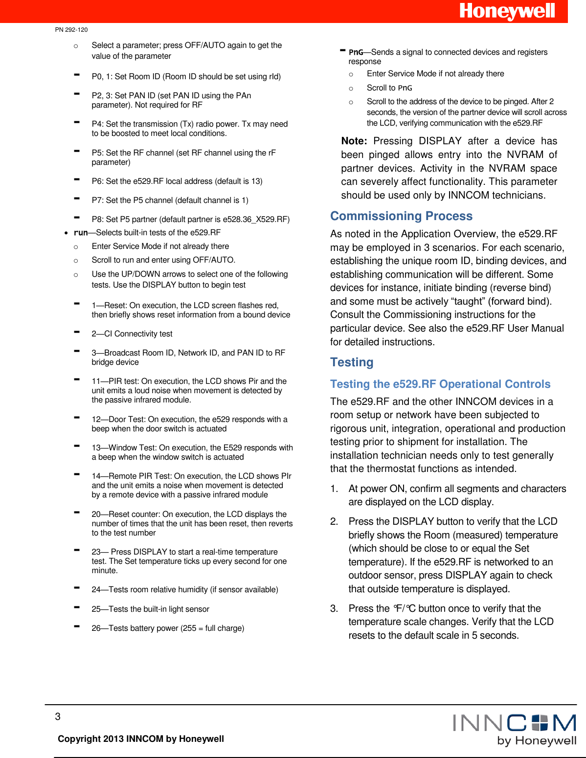
![PN 292-120 2 Copyright 2013 INNCOM by Honeywell Hook the tabs at the top rear of the e529.RF housing into the matching depressions at the top of mounting plate and rotate the bottom of the e529.RF housing toward the wall until it snaps into the place on the mounting plate. Secure the e529.RF housing to the mounting plate with the two small screws provided with the e529.RF. The screws thread into two small holes on the bottom of the e529.RF housing (see figure above). Service Mode The installation technician must enters the e529.RF’s Service Mode to set parameters for uniquely identifying a room, binding the INNCOM devices in the room to that identity, setting the operational characteristics of the devices, and, if necessary, connecting the room to floor- or building-wide network. Entering Service Mode To enter Service Mode 1. Press and hold the °F/°C button on the e529.RF 2. Press and release the OFF/AUTO button 3. Press and release the DISPLAY button 4. Release the °F/°C button Entering Values in Service Mode rId— Sets Room ID, a number that uniquely identifies the room to other device or on a network. Room ID consists of 5 digits divided into 3 bytes of data labeled HI_MED_LO (default is 6_55_35). The number will be included on the commissioning list and generally corresponds to the actual room number. o Enter Service Mode o At rId, press OFF/AUTO; the Room ID scrolls across the LCD, then the first digit (HI) appears o Use the UP/DOWN arrow to scroll to the first number of the Room ID entry from the commissioning list (HI values can be from 0 to 6) o Accept the HI number by pressing DISPLAY. The MED value will now show on the LCD o Enter the MED 2 digits in the same manner (value 0–99). LCD shows LO o Enter the LO 2-digit value (0–99). On pressing DISPLAY, the new rId will scroll across the LCD, then the e529.RF returns to the menu list PAn—The ID number of a network coordinating device, e.g., a B574, in a network bridge application. The number will be included on the commissioning list. o Enter Service Mode if not already there o Scroll to PAn and press OFF/AUTO o Use the UP/DOWN arrows to find the PAN ID on the commissioning list o Press DISPLAY. The e529.RF beeps to confirm the Pan ID value is stored, and the LCD returns to the menu list rF—Selects the RF channel for IRAS communication. The number will be included on the commissioning list. o Enter Service Mode if not already there o Scroll to rF and enter using OFF/AUTO o Use UP/DOWN to set the RF channel between 11 and 26 o Press DISPLAY. The e529.RF beeps to confirm the value is stored and the LCD returns to menu Adr—Used to “teach” IRAS devices the unique identification information (e.g., Room ID, PAN ID, I/O map for a room) that binds them to a room or network. o Enter Service Mode if not already there o Scroll to Adr and enter using OFF/AUTO o Prepare the partner device to learn from the e529.RF o Scroll to the Address for the device to be taught (from the commissioning list) o Press DISPLAY. The unit will send the teach command on all RF channels (11–26), then the LCD displays the selected address o Accept in partner device Note: When in Address mode, the FAN button can be used to Reset the target device. Io—Used to configure the Input/Output map of a partner device. [Note: Some INNCOM devices can have variable roles in a room, e.g., an S217 can be configured to control a light or a switch. The device roles are contained in the I/O map.] o Enter Service Mode if not already there o Scroll to Io and enter using OFF/AUTO o Prepare the partner device to learn from the e529.RF o Scroll to the Address for the device to be taught (from the commissioning list) o Press DISPLAY. The unit sends the I/O map out over all channels Note: Whenever a device is taught information, it is important to verify that the instruction was received and accepted by “pinging” the device. See PnG below. SEr—In legacy (3G) e529s, configures CBL8 Partner (Server) devices (e.g., X07). The e529.RF will eventually be able to configure CBL32 devices (e.g., X47) from here. Press DISPLAY to write parameters; press FAN to execute them. Loc—Menu of local parameters. This menu is typically not used by Installation Technicians. The entry below is provided solely for informational purposes. The list of local parameters below will change and grow. o Enter Service Mode if not already there o Scroll to Loc and enter using OFF/AUTO. The LCD shows a “P” and a number for each parameter (0–255).](https://usermanual.wiki/Honeywell/202153TXR/User-Guide-2371008-Page-2.png)