ID TECH VP3600 VP3600 User Manual
ID TECH VP3600 Users Manual
UserManual.wiki
>
ID TECH
>
VP3600 User Manual
Users Manual
Navigation menu
Upload a User Manual
Namespaces
Wiki Guide
HTML
PDF
Info
Views
User Manual
Discussion / Help
Navigation

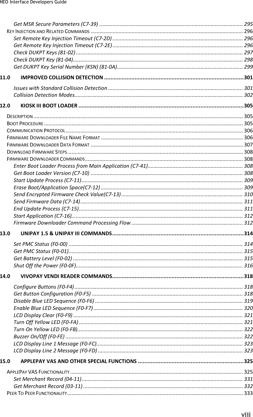

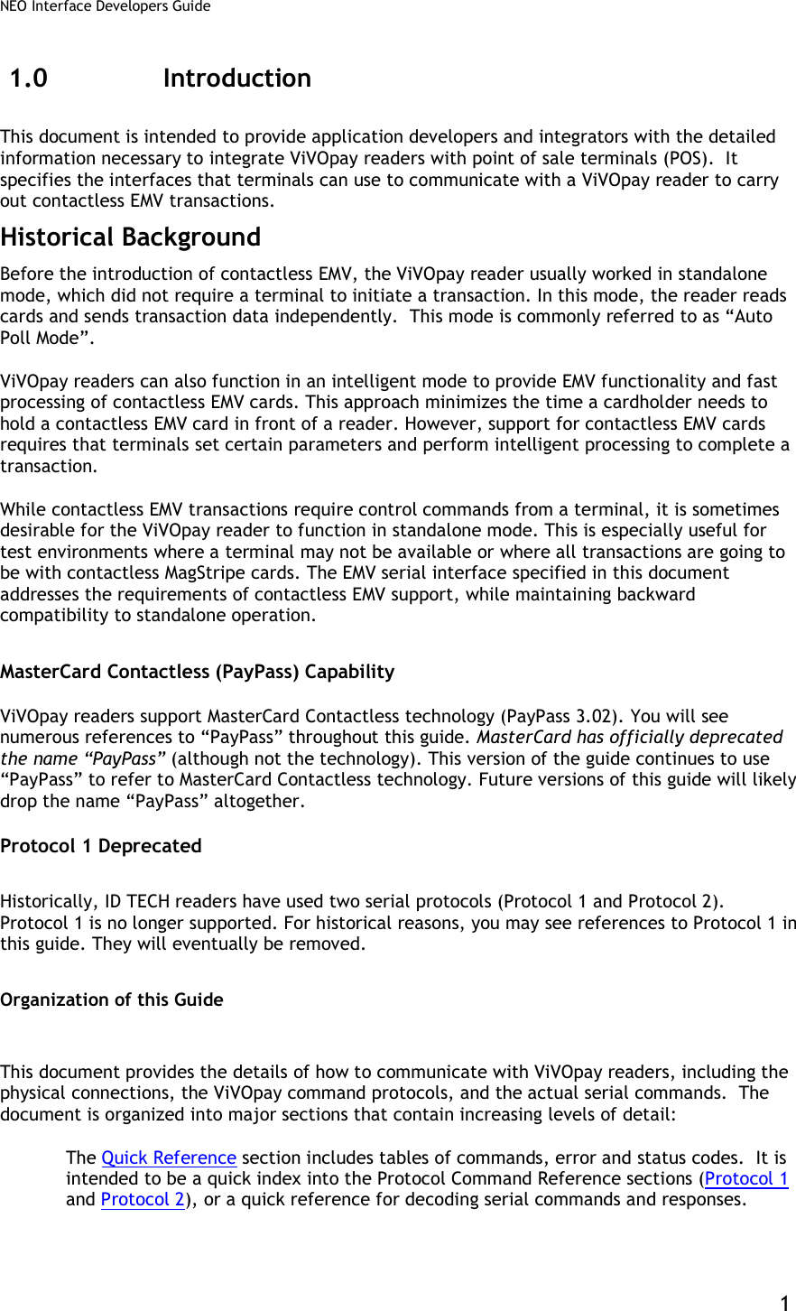
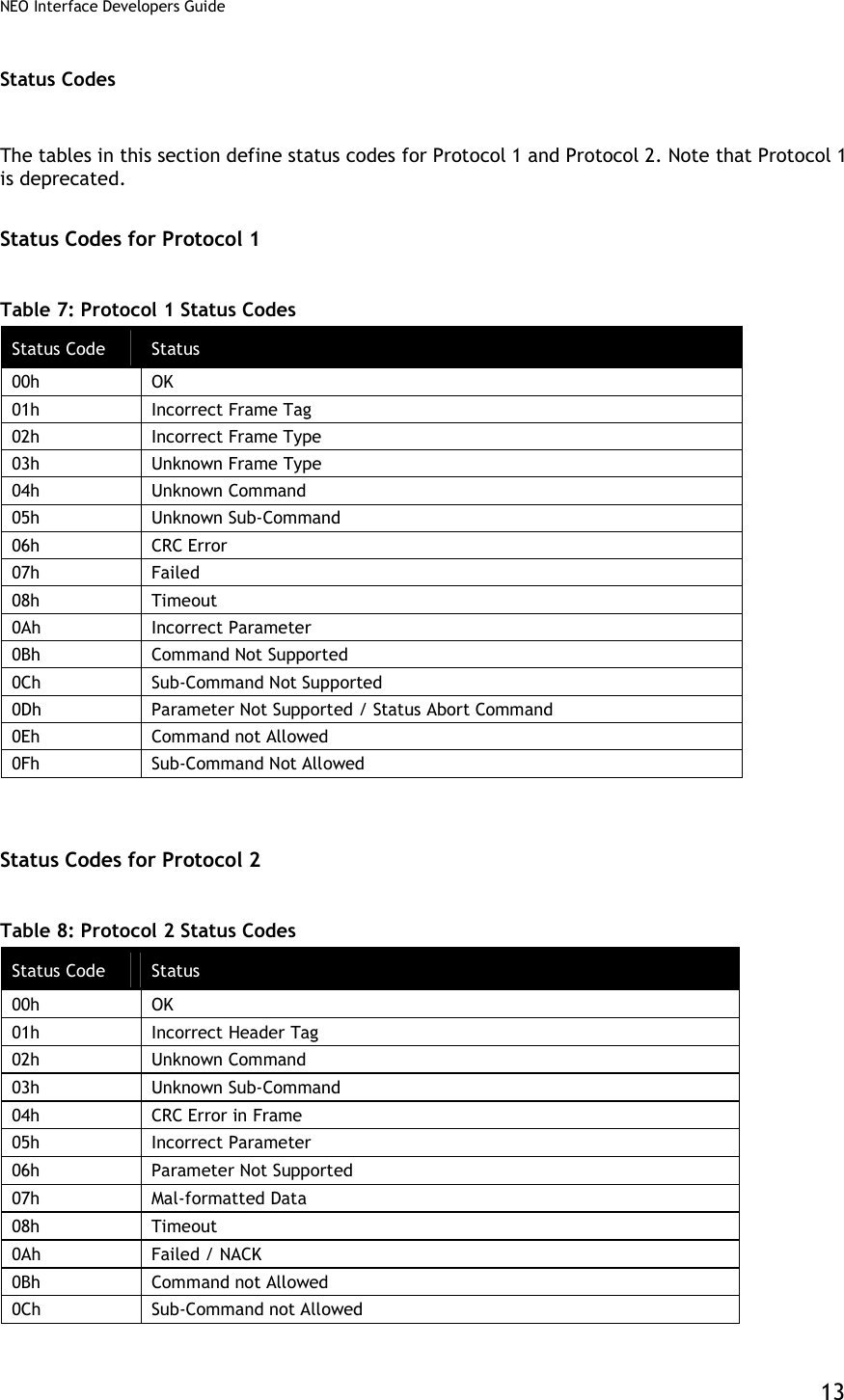
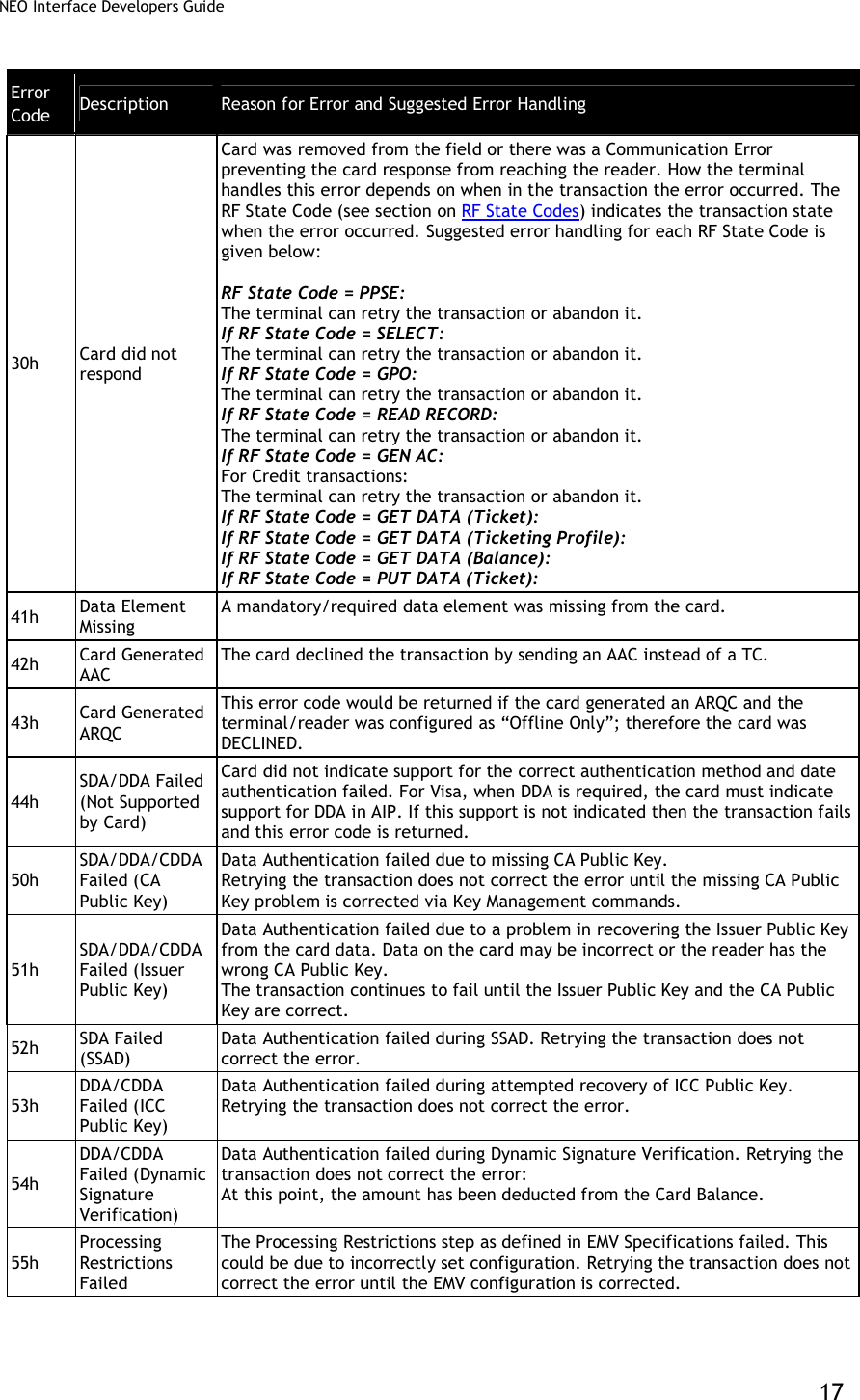
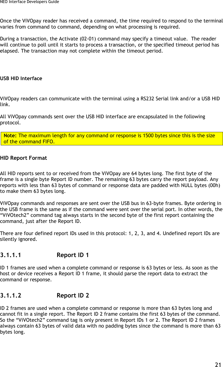
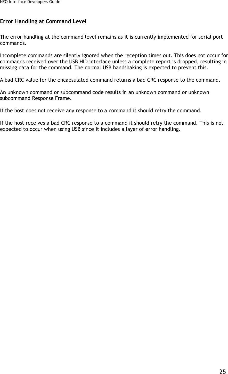
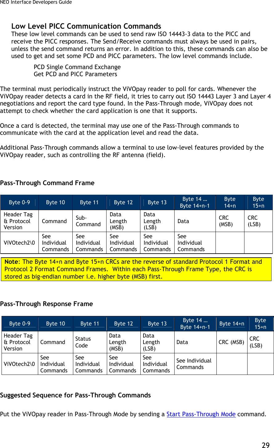

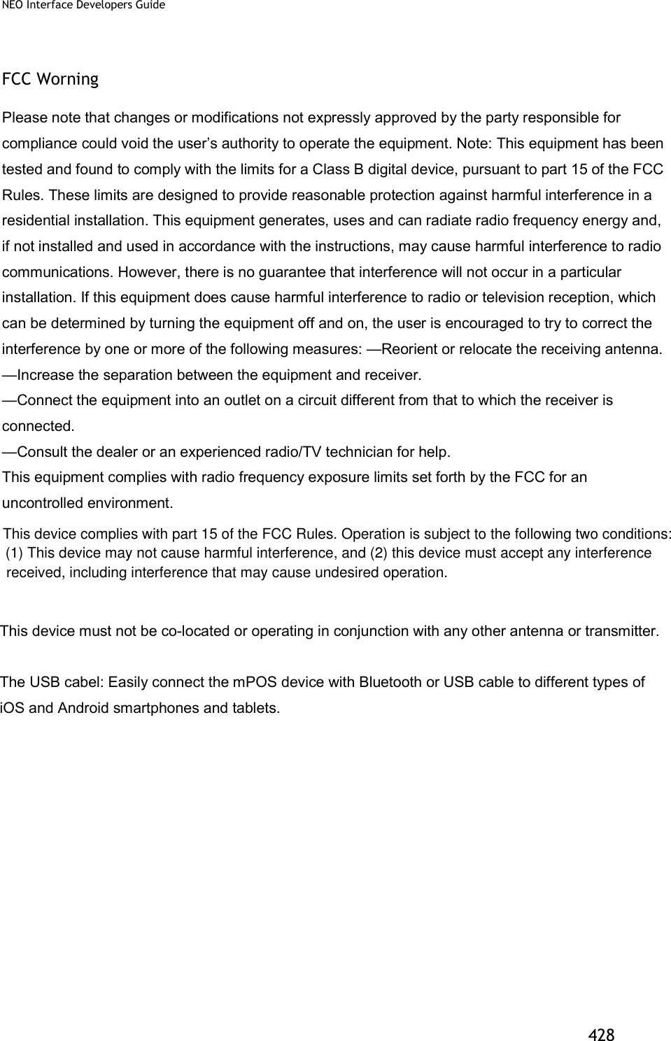
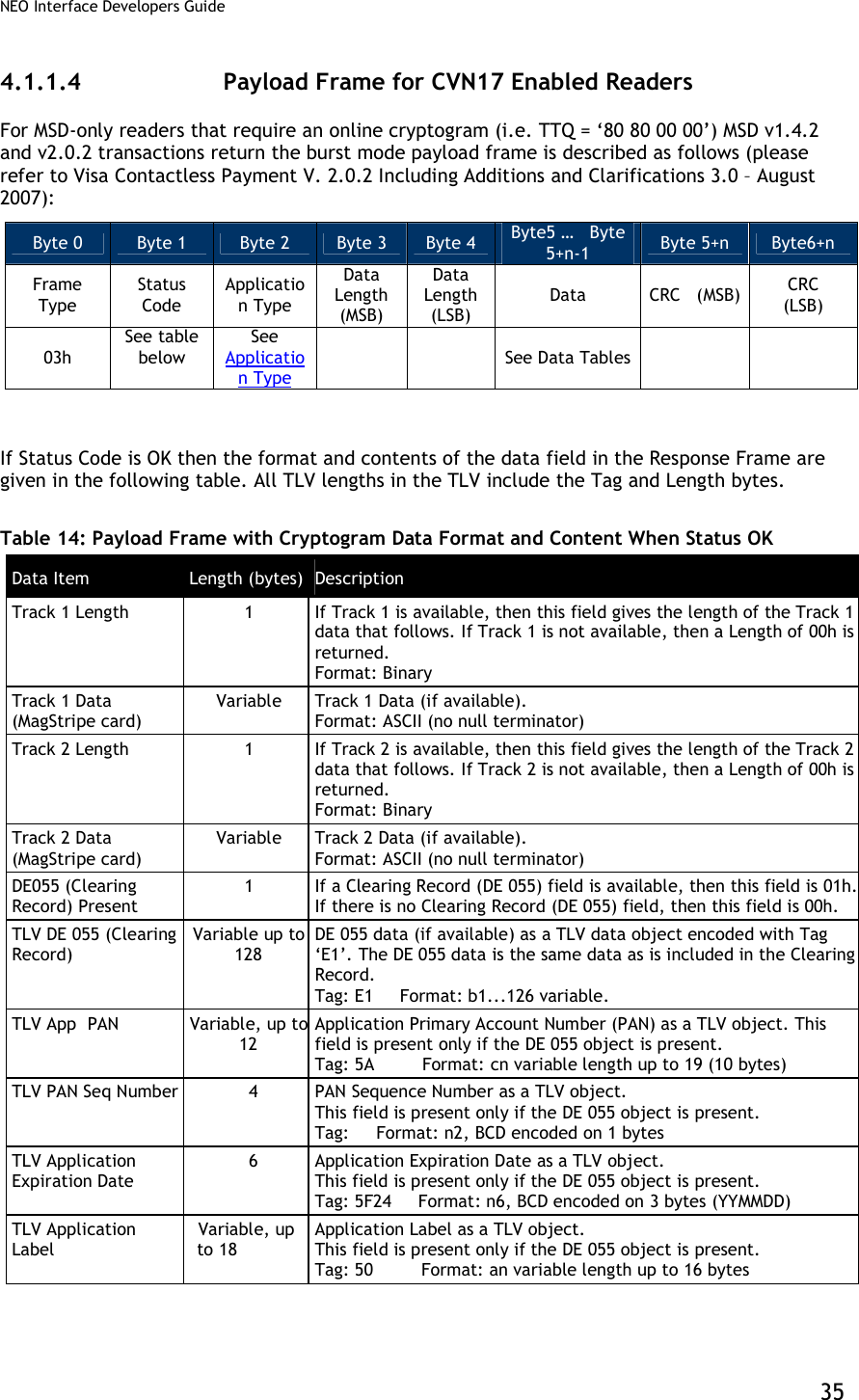
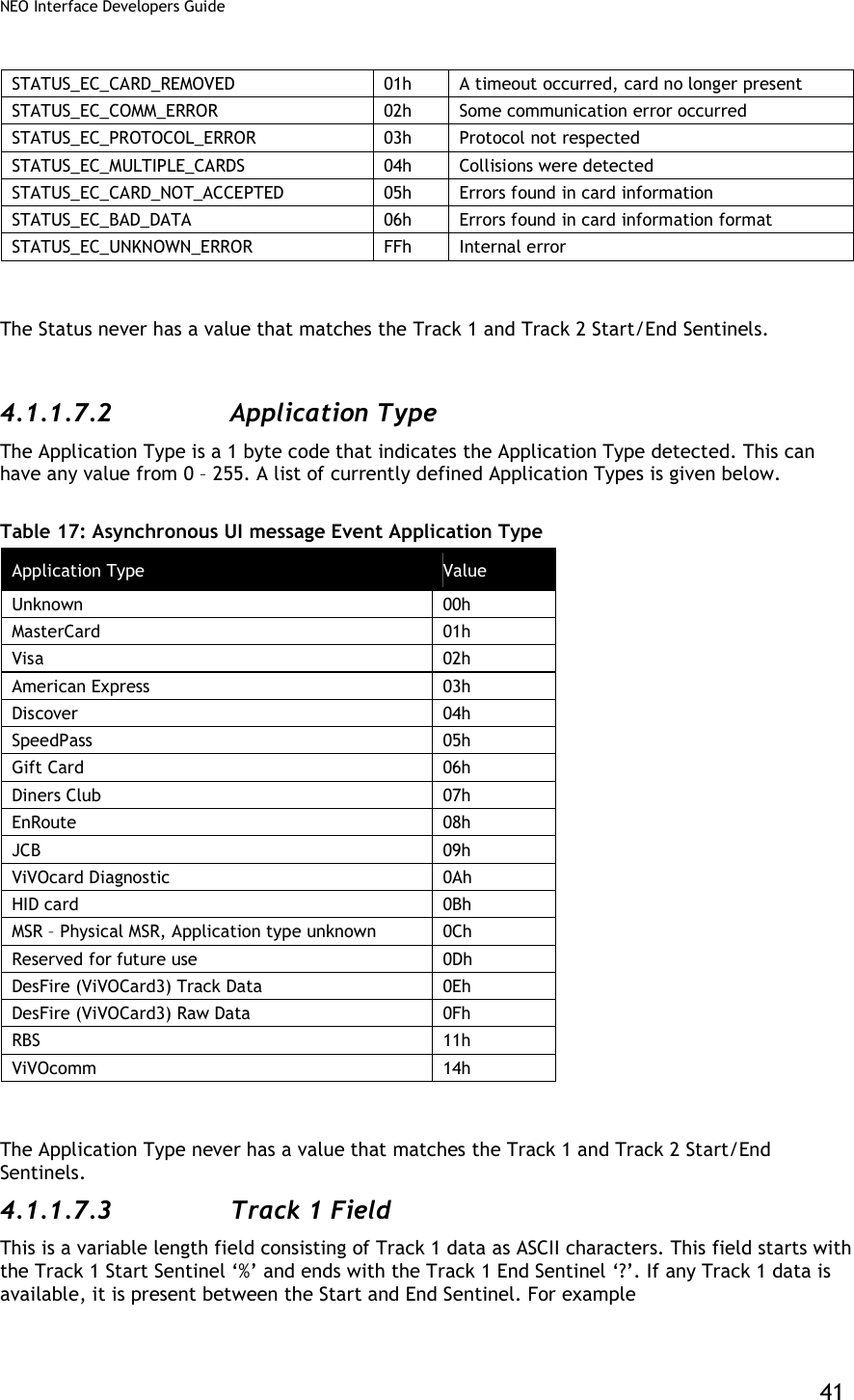
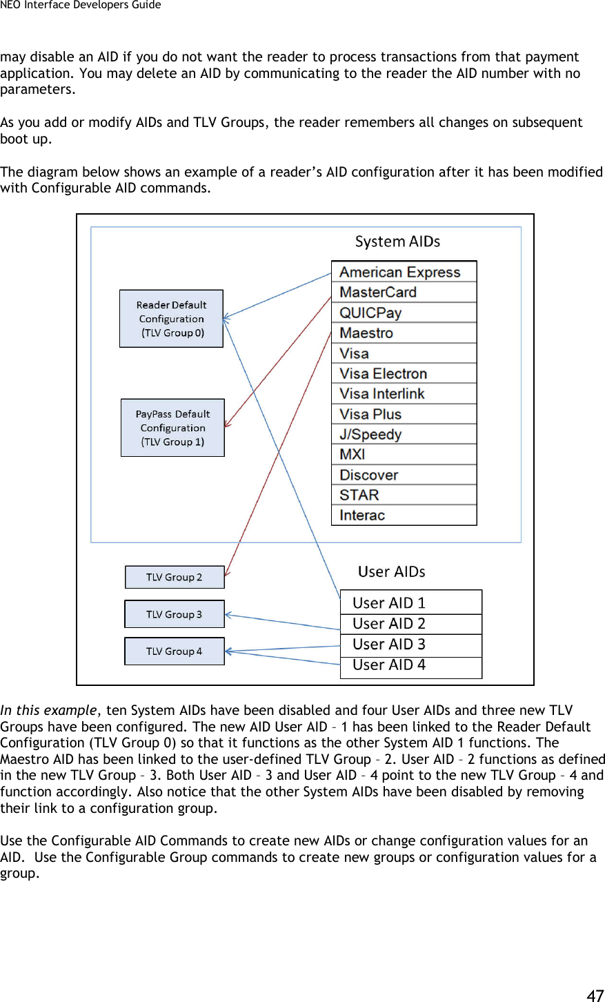
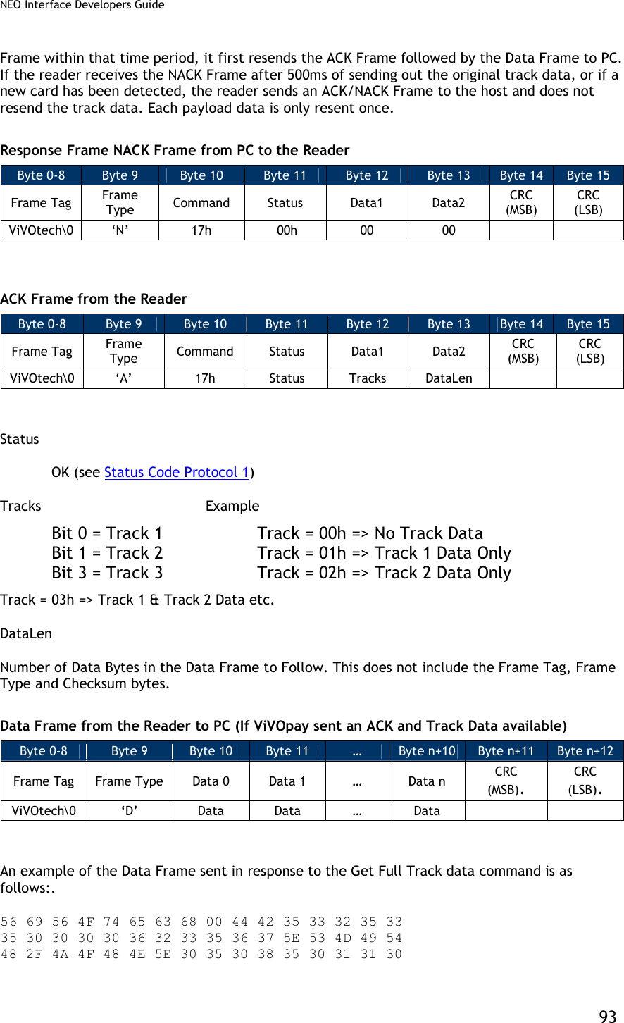
![NEO Interface Developers Guide 34 ViVOpay Burst Mode Frames The table below describes the Burst Mode frame types. The frame type appears in Byte 0 of a Burst Mode packet. Table 13: Burst Mode Frames Frame type Description 01h Payload Frame 02h Status Frame 03h Payload Frame for VISA MSD 202 CVN17 type transaction 55h NACK 0Eh Asynchronous Event Frame 4.1.1.3 Payload Frame (On Successful Read) On successful read ViVOpay sends a Card Payload frame to the terminal that always contains Frame Type, Status and Application Type. The Status always shows Success (=00). The Application Type can have any of the values defined in the “Data Definitions” section. This is followed by the track data. Only those tracks the reader was able to read from the Card are sent. Each Track begins and ends with its Start and End Sentinel. After the Track Data, the reader sends two CRC bytes. The details of the CRC algorithm used are given in the “CRC Calculation” section. Byte 0 Byte 1 Byte 2 Byte n-1 Byte n Frame Type =01h Status =00h Application Type Track 1 Field (if found) Track 2 Field (if found) CRC (MSB) CRC (LSB) Example 1: Payload, Card Read Successfully, Application Type Visa, Both Track 1 and Track 2 Present [01] [00] [02] %B123456789^ABCDEF^12345678?;123456=12345?<CRC1><CRC2> Example 2: Payload, Card Read Successfully, Application Type MasterCard, Only Track 2 Present [01] [00] [01] ;123456=12345?<CRC1><CRC2> Example 3: Payload, Card Read Successfully, Application Type AmEx, Only Track 1 Present [01] [00] [03] %B1234567^ABCDEF^12345678? <CRC1><CRC2> Example 4: Payload, Card Read Successfully, Application Type Unknown, Both Track 1 and Track 2 Present [01] [00] [00] %B123456789^ABCDEF^12345678?;123456=12345? <CRC1><CRC2>](https://usermanual.wiki/ID-TECH/VP3600/User-Guide-3704675-Page-46.png)
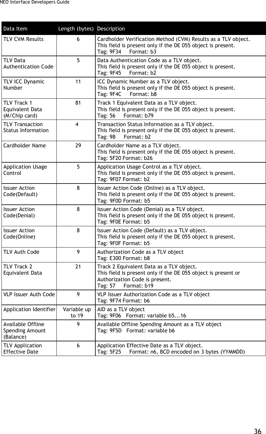
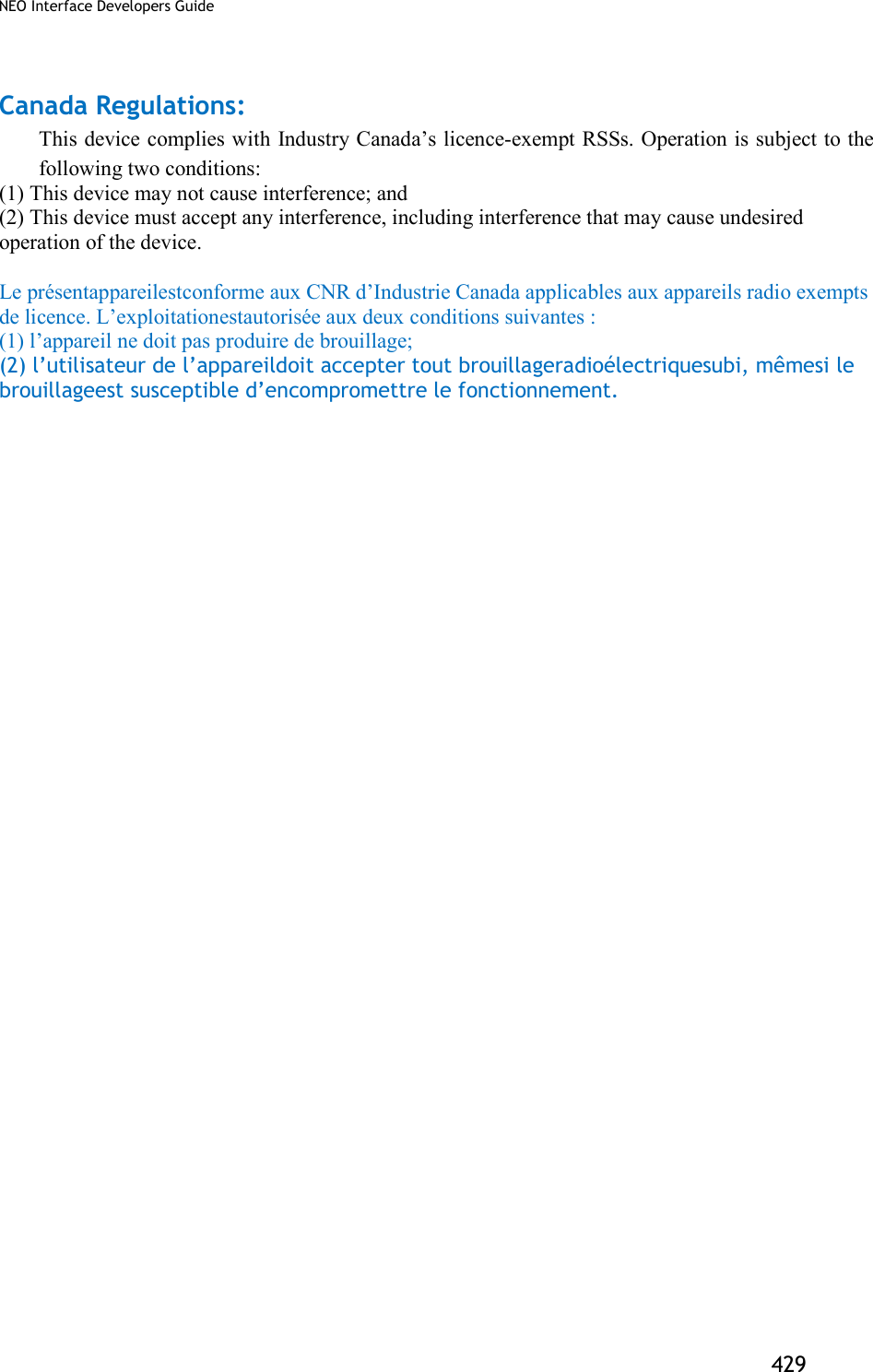
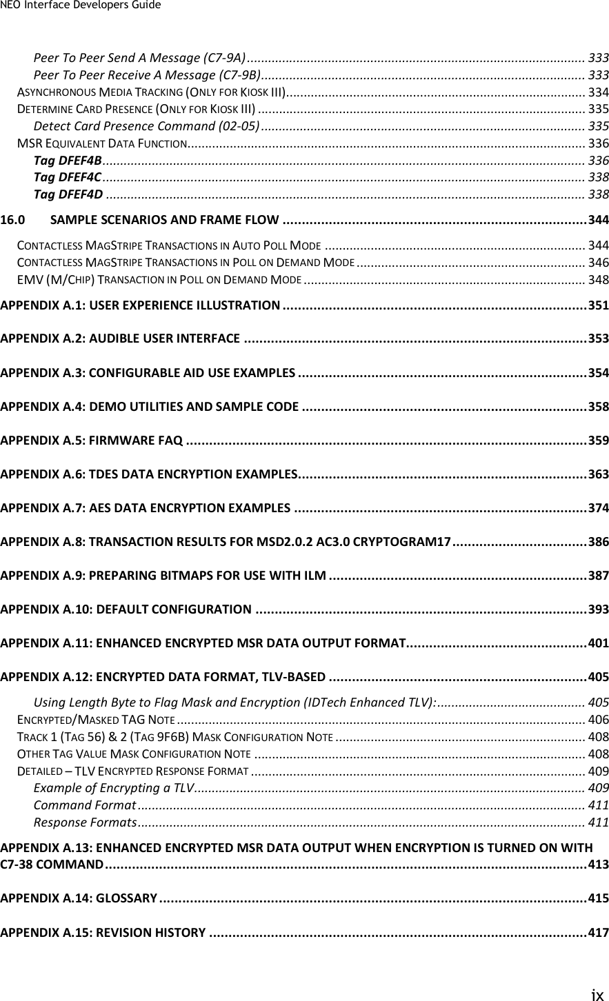
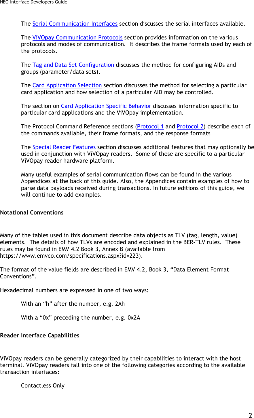
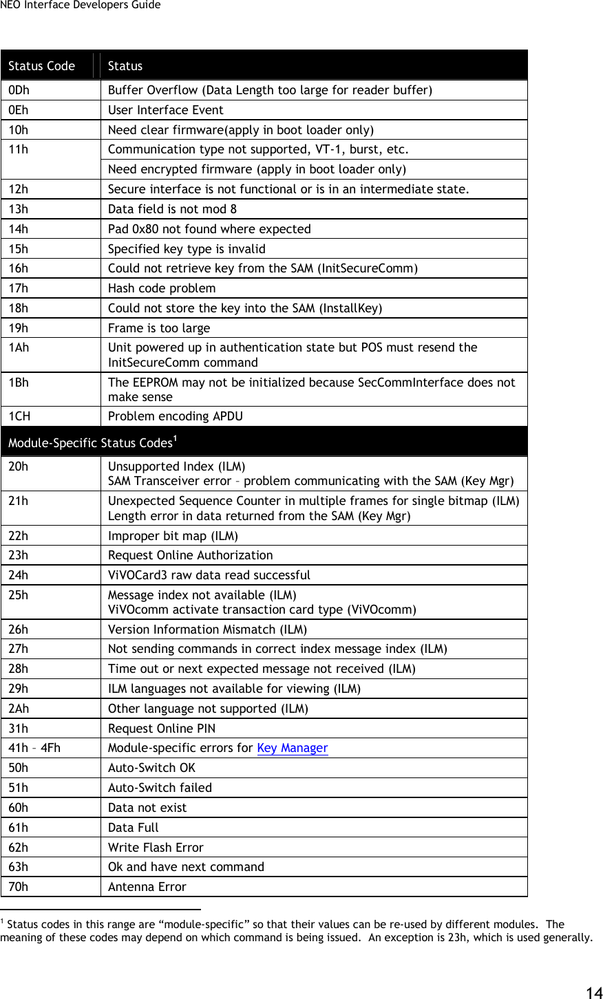
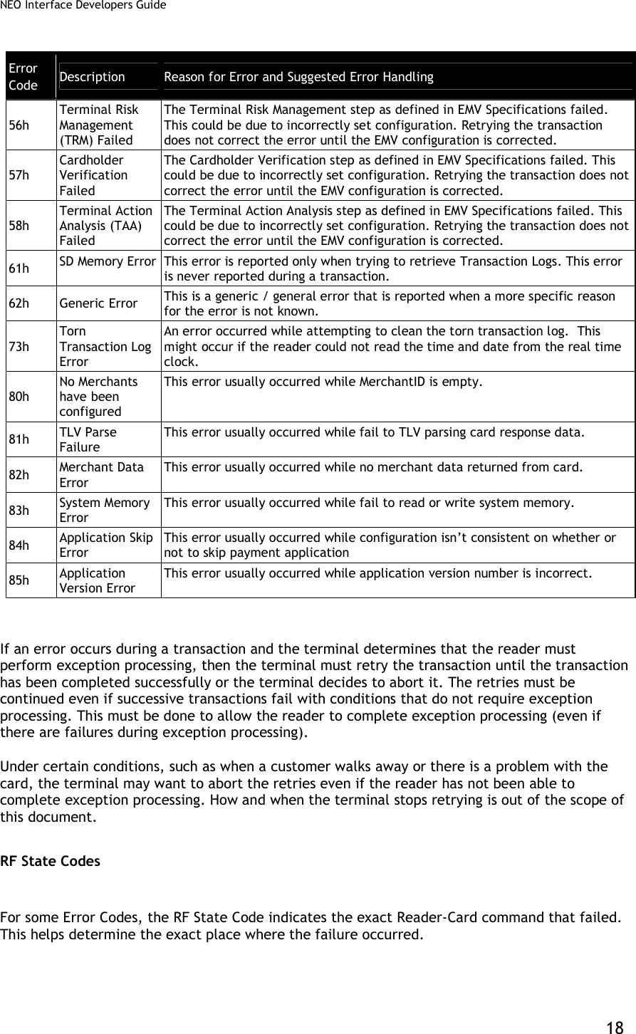
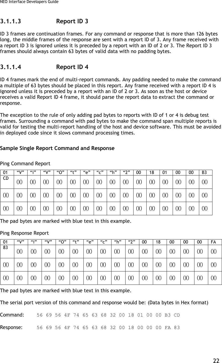
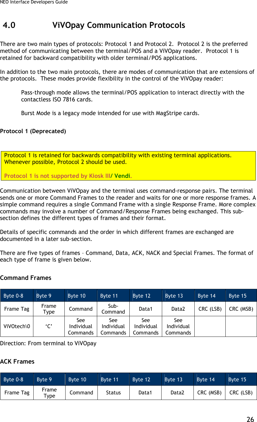
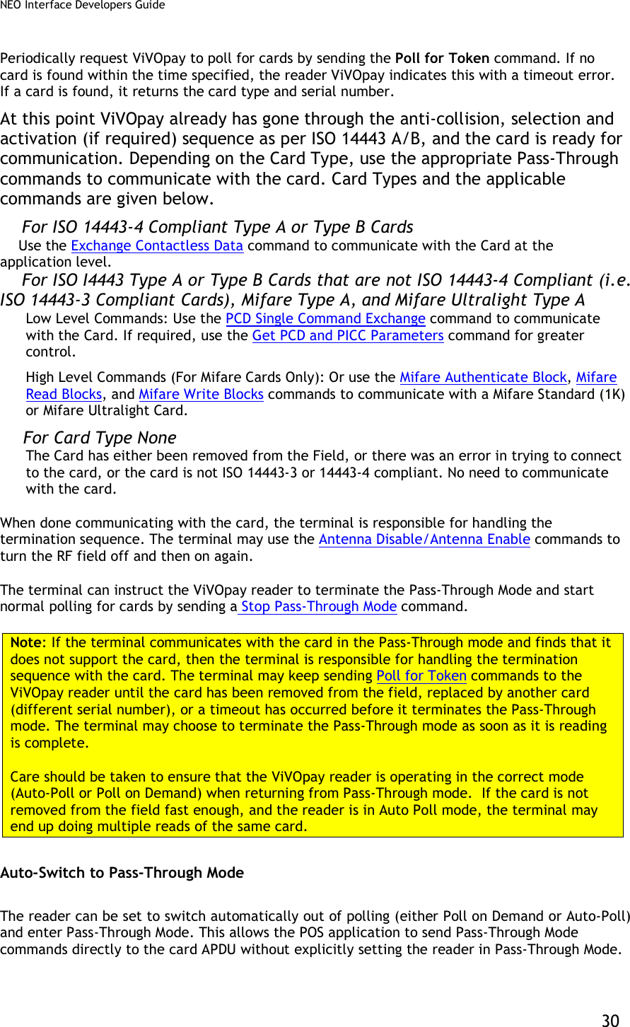
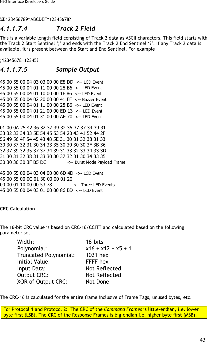
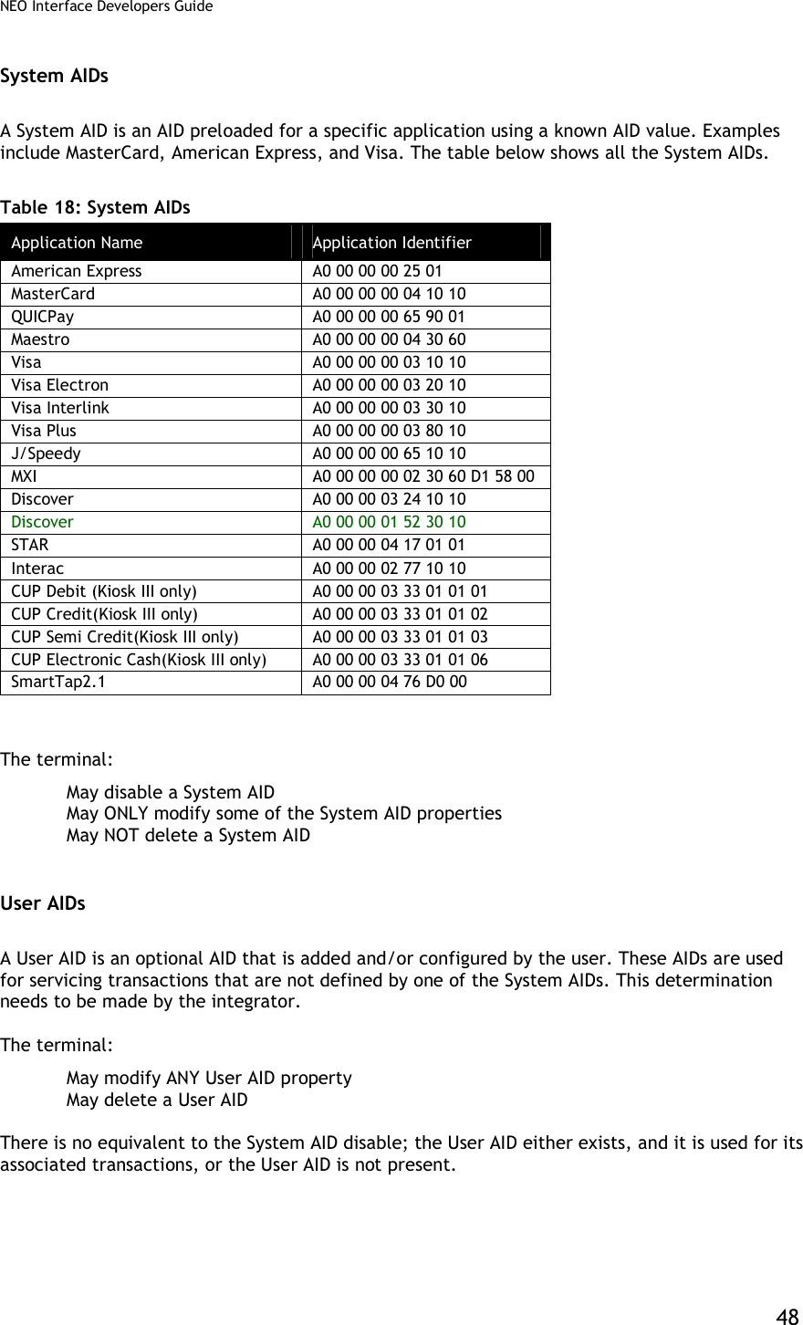
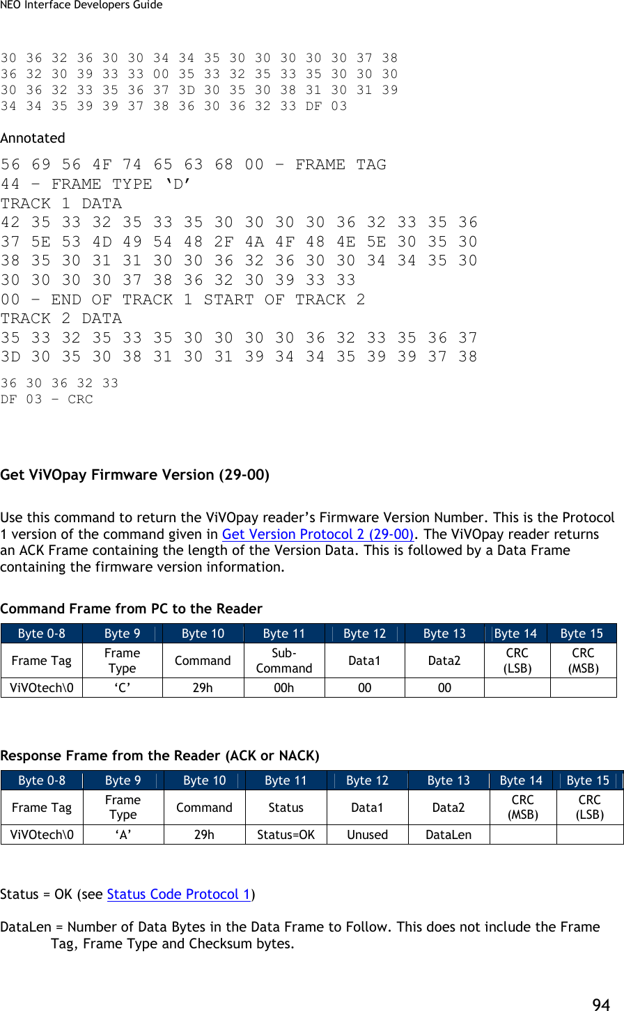
![NEO Interface Developers Guide 38 Example 1: ViVOpay receives NACK frame from terminal within 500ms after sending the original payload data, ViVOpay resends the card payload data. Terminal ViVOpay Reader Original Payload --------------------------------------------------------------------- | Time: 0 | NACK sent at 400ms (within 500ms) | -------------------------------------------------------------------- | Time: 400ms | Resend Payload | --------------------------------------------------------------------- | ▼ Original Payload: Payload, Card Read Successfully, Application Type Master Card, Both Track 1 and Track 2 Present [01][00][01]%B5325350000623567^840SMITH/JOHN^05085011492563892473?;5325350000623567=05081019492993892483? <CRC1><CRC2> Resent payload: Payload, Card Read Successfully, Application Type Master Card, Both Track 1 and Track 2 Present [01][00][01]%B5325350000623567^840SMITH/JOHN^05085011492563892473?;5325350000623567=05081019492993892483? <CRC1><CRC2>](https://usermanual.wiki/ID-TECH/VP3600/User-Guide-3704675-Page-50.png)
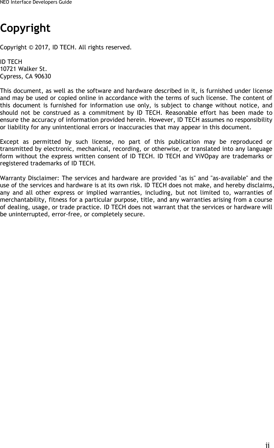
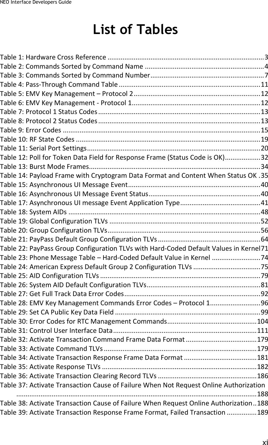
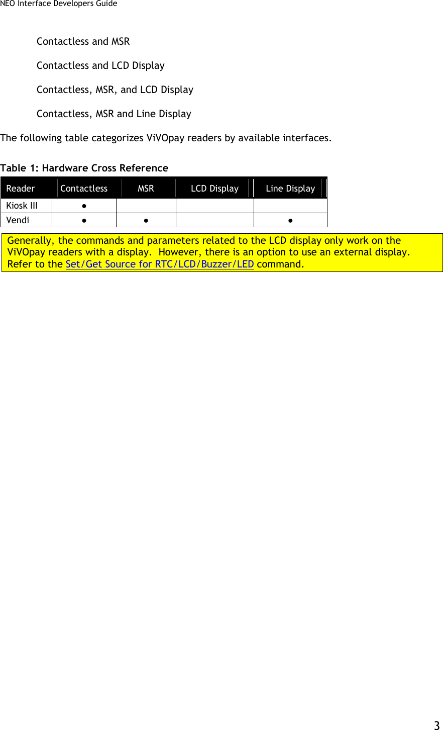
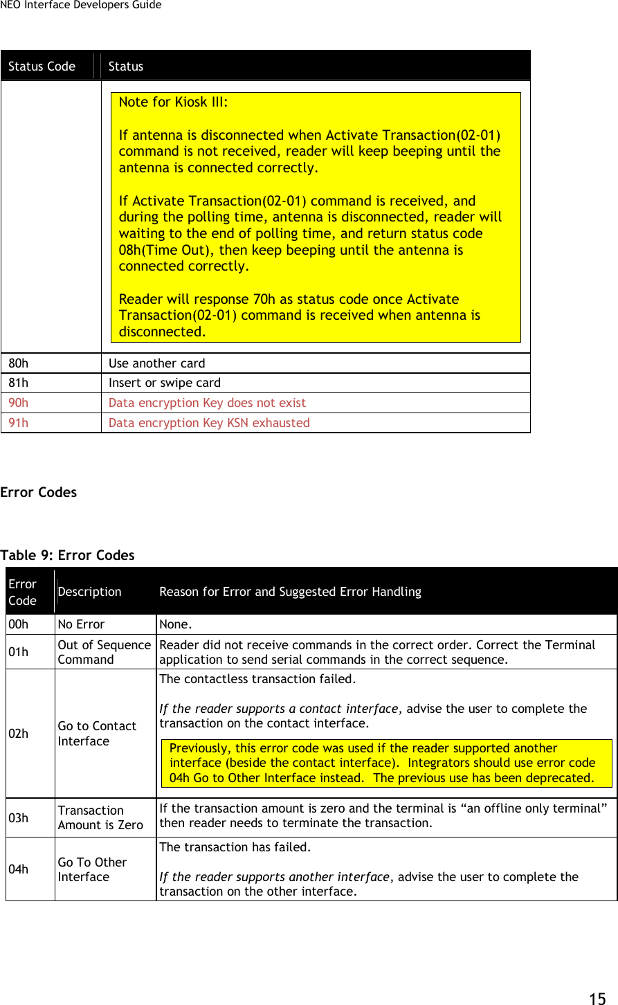
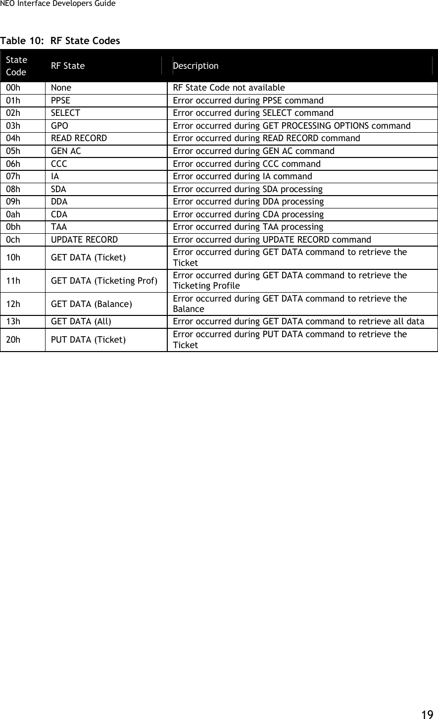
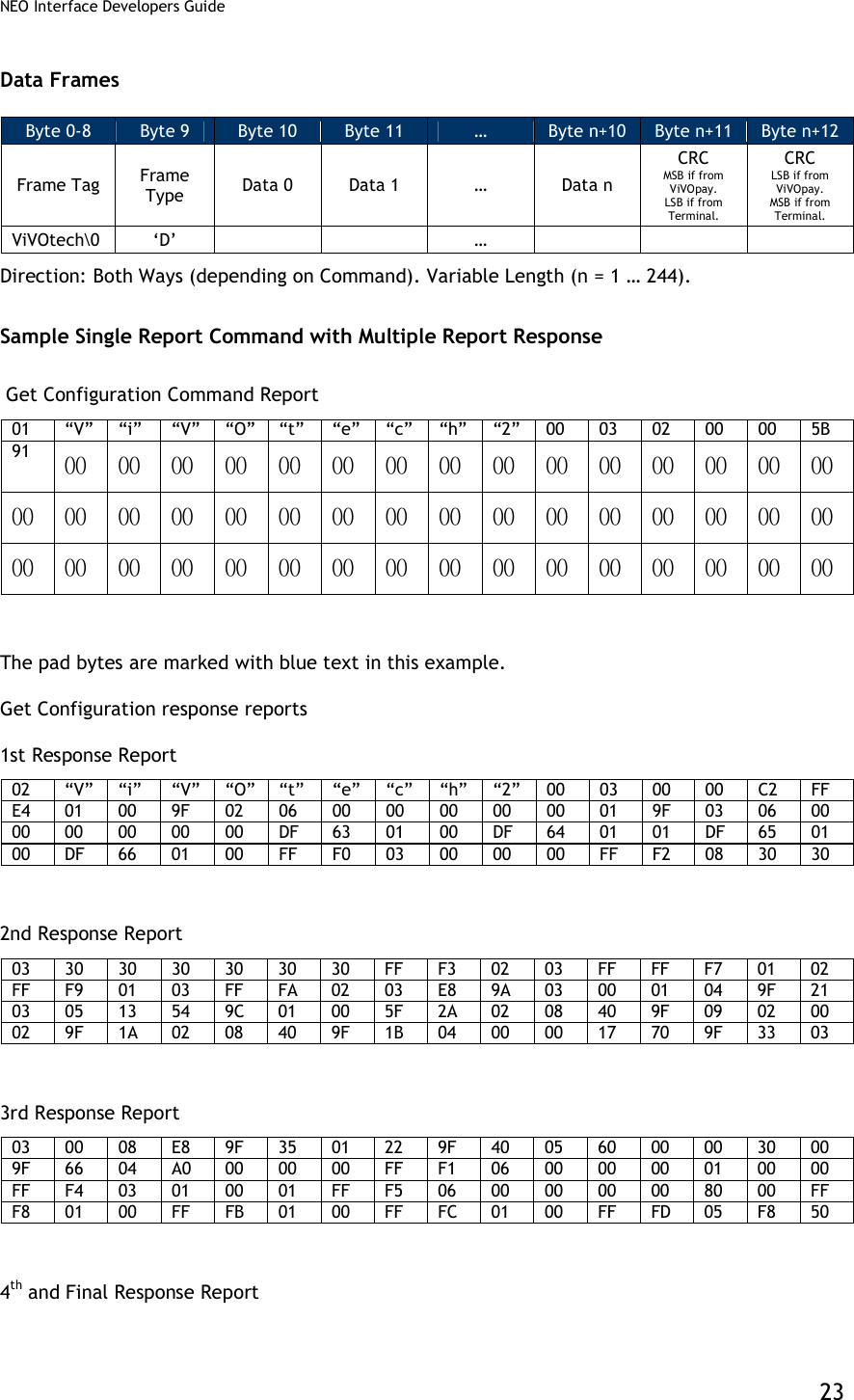
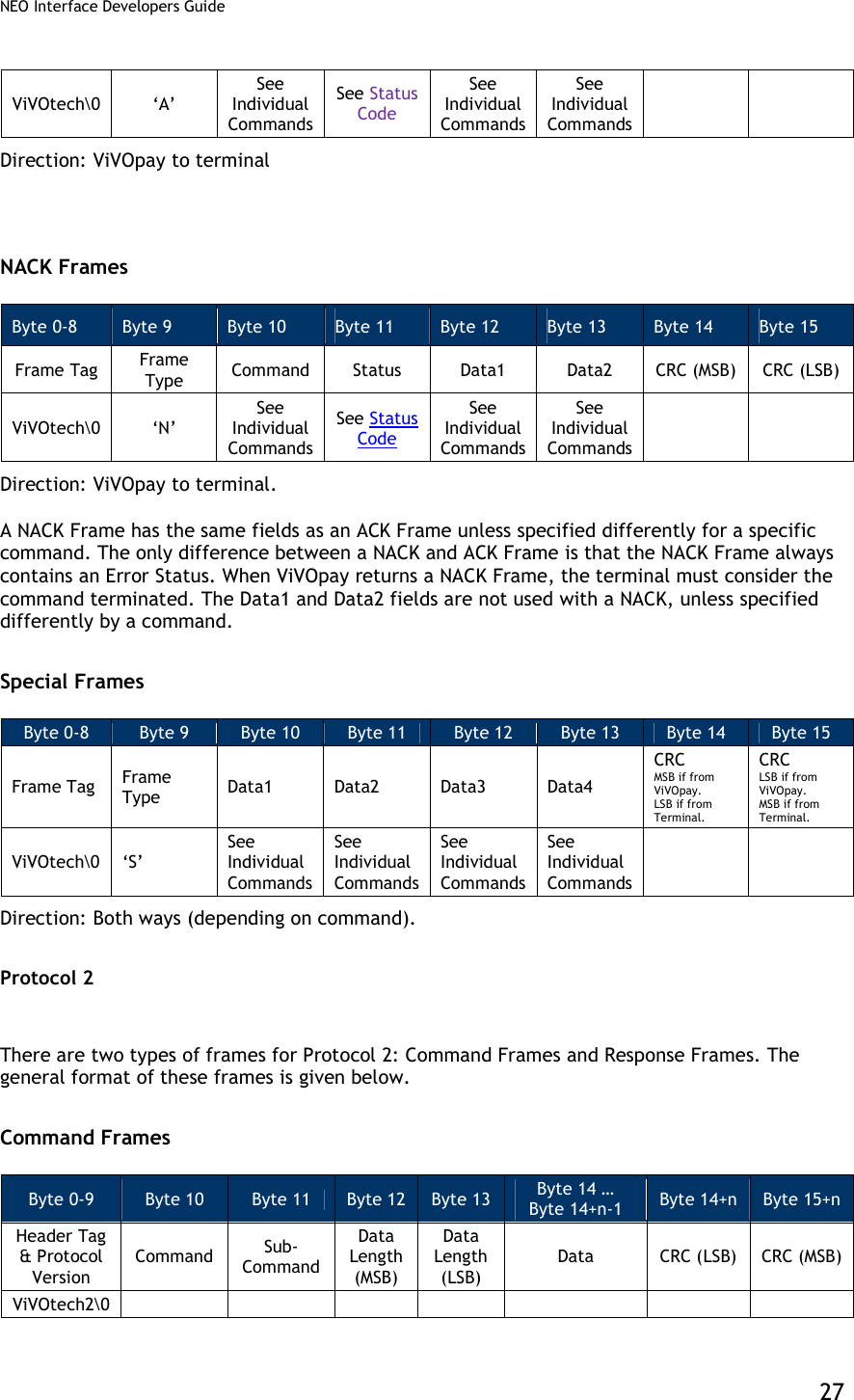
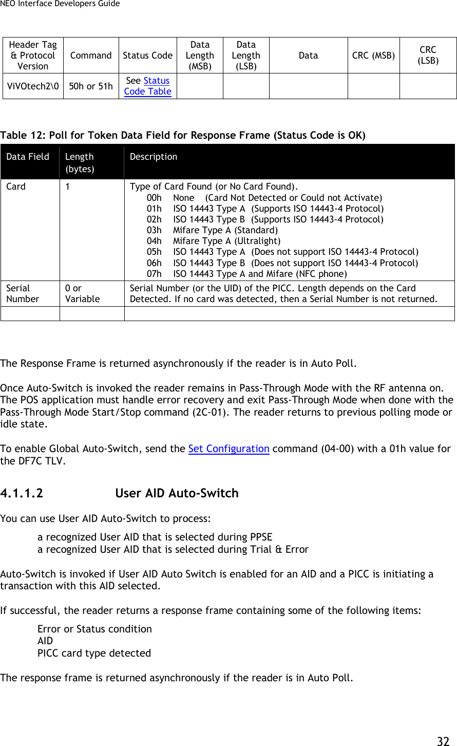
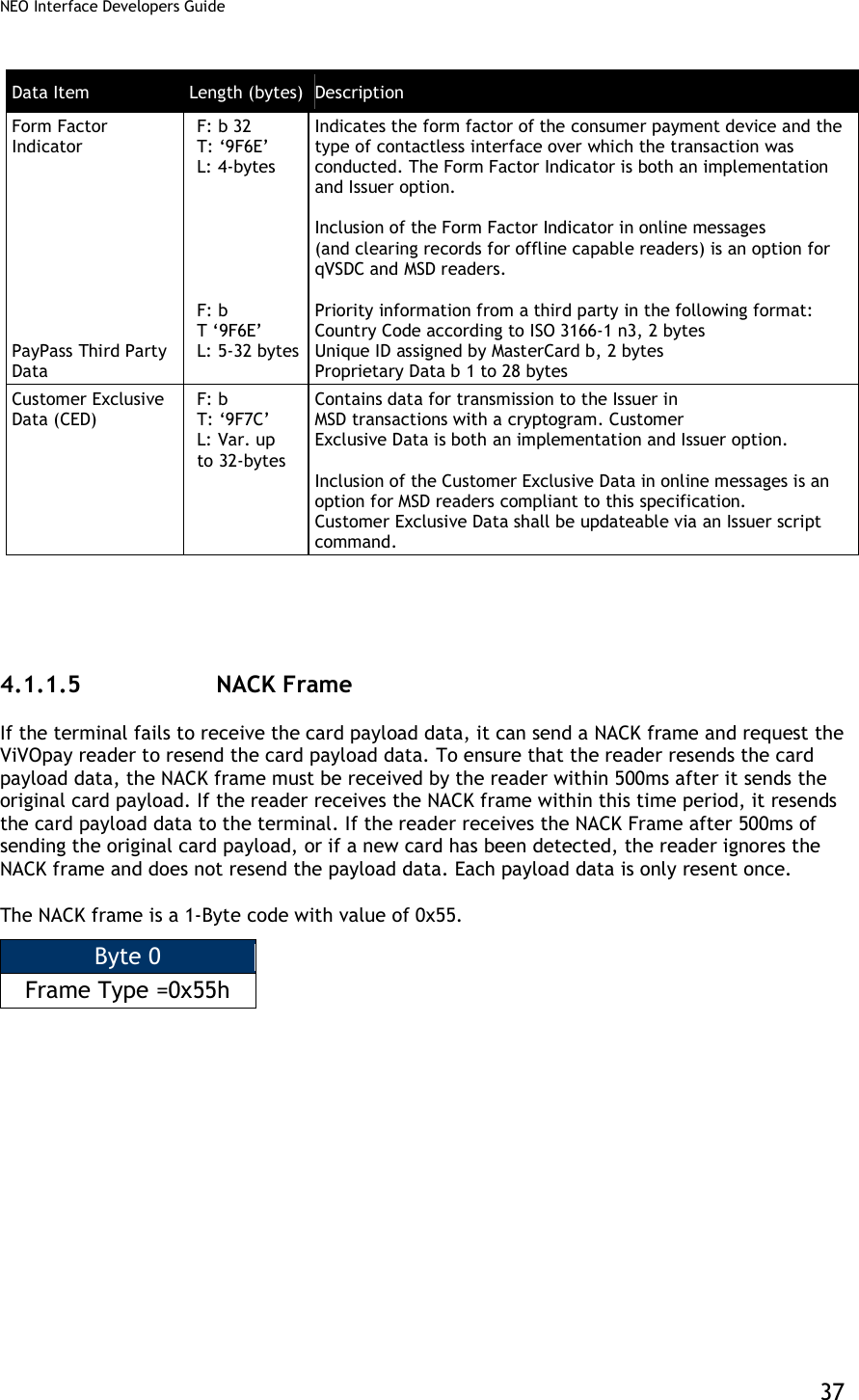
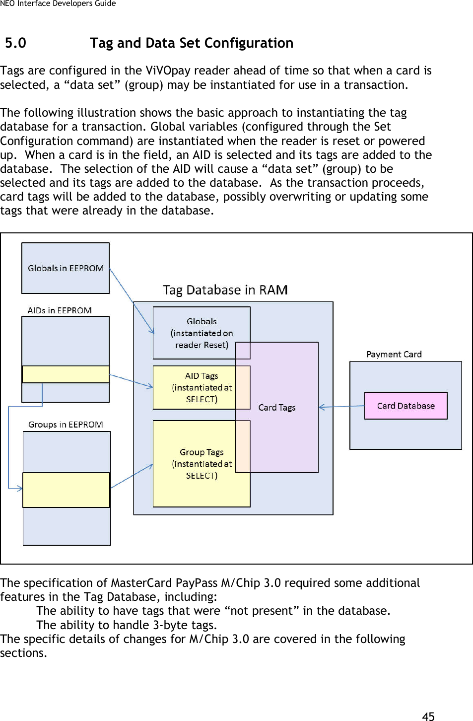
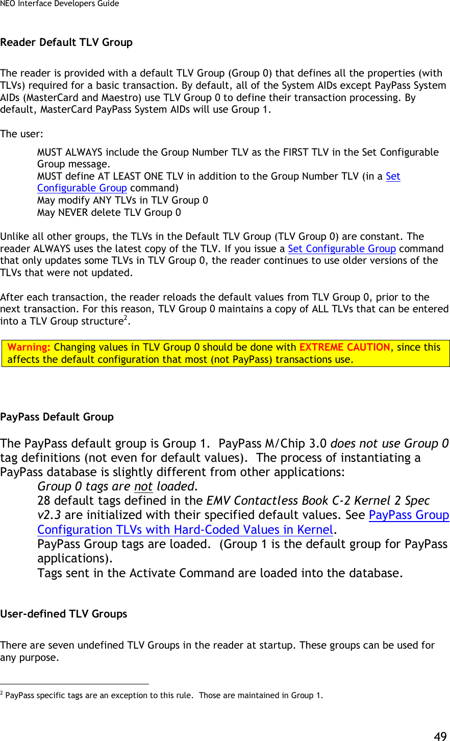
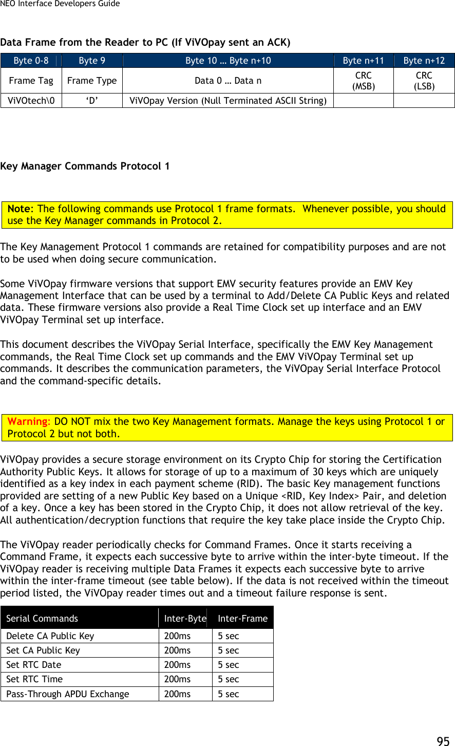
![NEO Interface Developers Guide 39 Example 2: Reader receives NACK frame from terminal after 500ms of sending the original payload data, the reader does not resend the card payload data. Terminal ViVOpay Reader Original Payload --------------------------------------------------------------------- | Time: 0 | | | | NACK sent at 700ms (after 500ms) | -------------------------------------------------------------------- | Time: 700ms | | No Resend Payload | ▼ Original card payload data (no resent payload data): Payload, Card Read Successfully, Application Type American Express, Both Track 1 and Track 2 Present [01][00][03]%B379013539021002^TEST/CARD001^0604718000877840?;379013539021002=060471800087784000102? <CRC1><CRC2> 4.1.1.6 Asynchronous UI Message Event Asynchronous message event is used by the reader to indicate specific events to the terminal. These frames are only sent when LCD and LED are sent to external source. In synchronizing with the transaction, the reader can send asynchronous user interface (UI) message event to the terminal to specify the required user experience on the terminal. Following is the format definition of Asynchronous UI Message Event: Byte 0 Byte 1 Byte 2 Byte 3 Byte 4 Byte 5 & 6 … Bn-3 Bn-2 Bn-1 Bn Frame Type 45h, E Status =00h Event Type 55h, UI Scheme, defined on tag ‘FF F8’ Length Byte 2 Byte UI Event Additional 2 Byte UI Events Null Character Null Character CRC (MSB) CRC (LSB)](https://usermanual.wiki/ID-TECH/VP3600/User-Guide-3704675-Page-51.png)
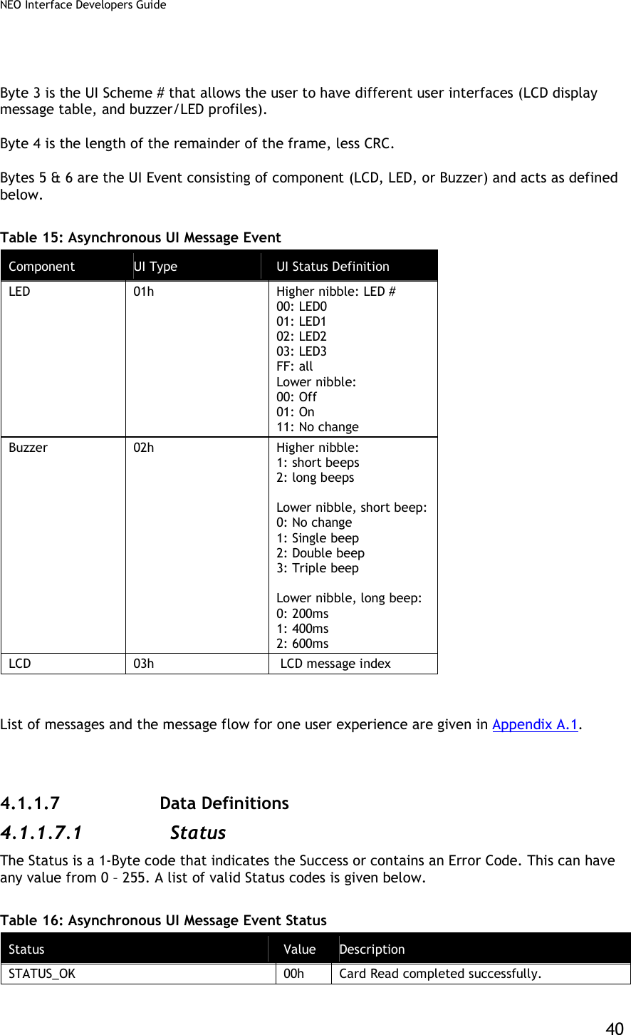
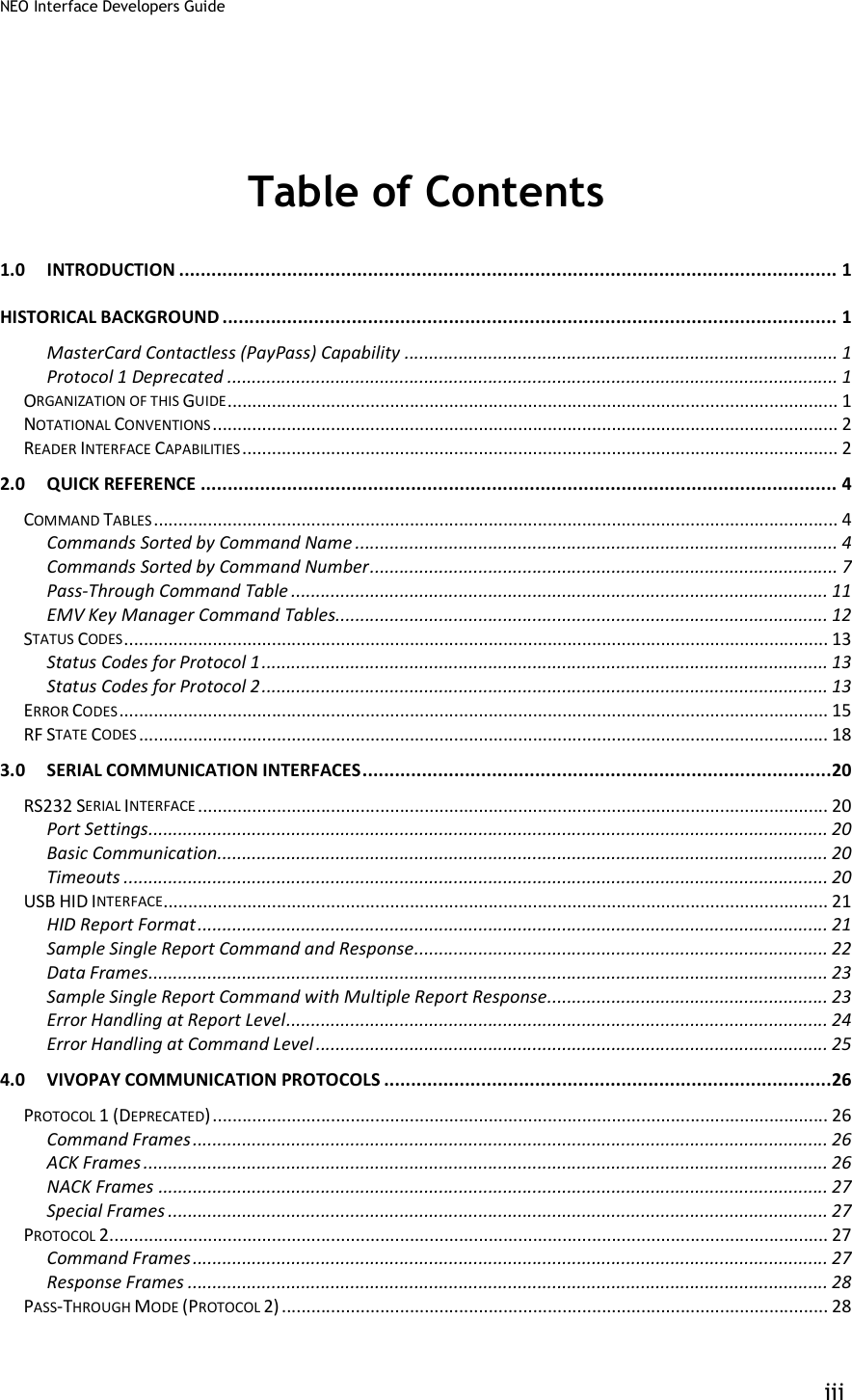
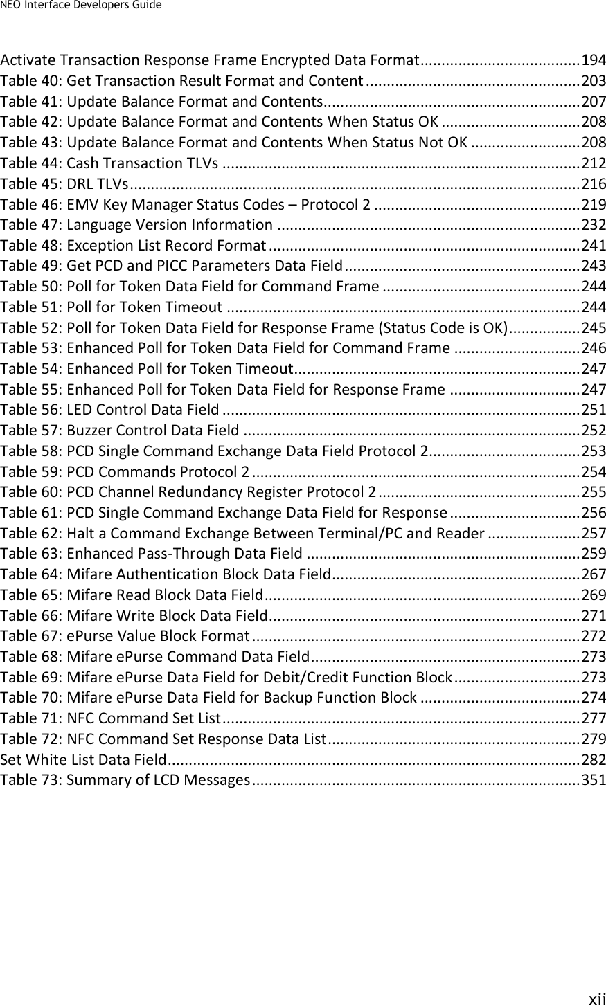
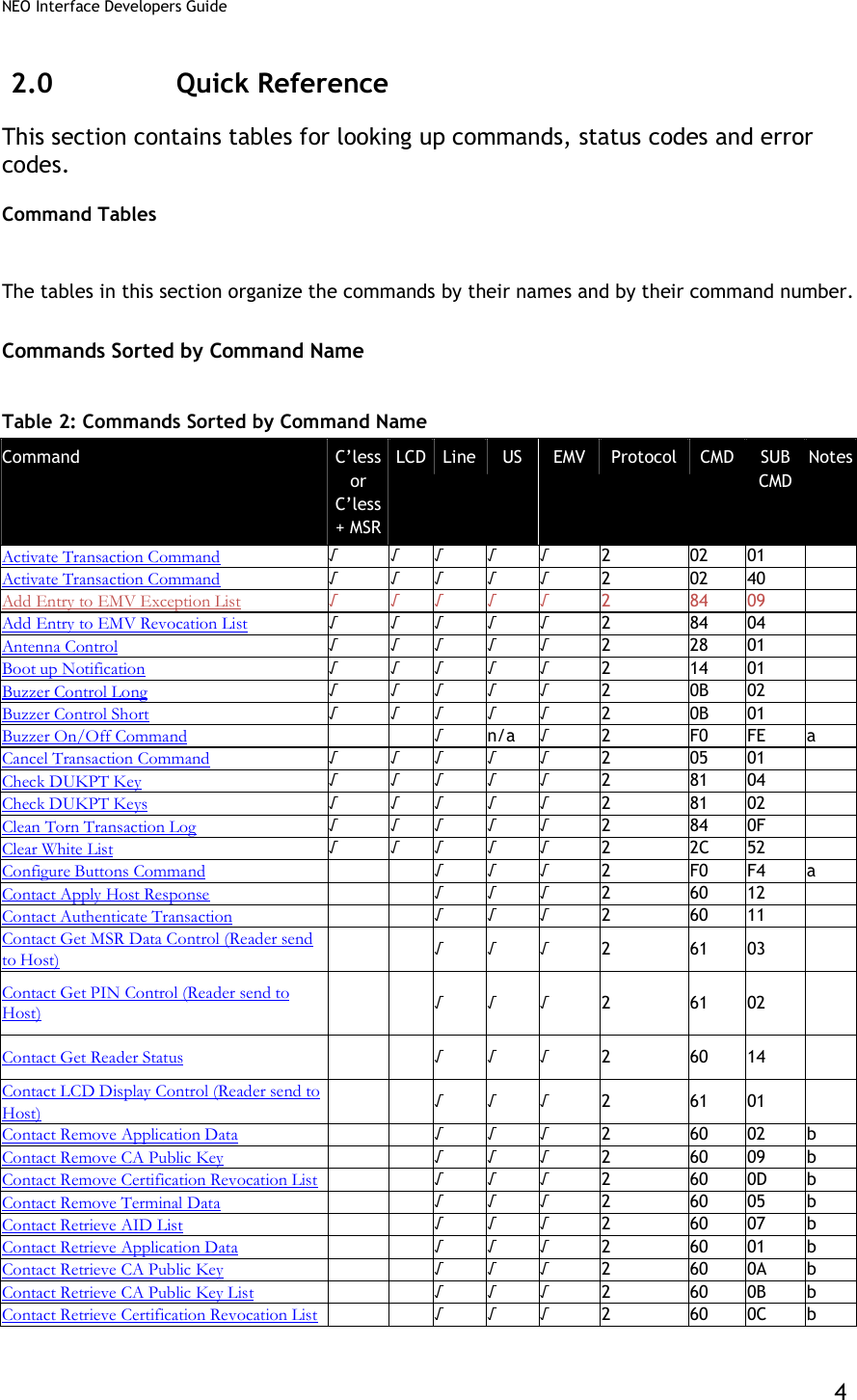
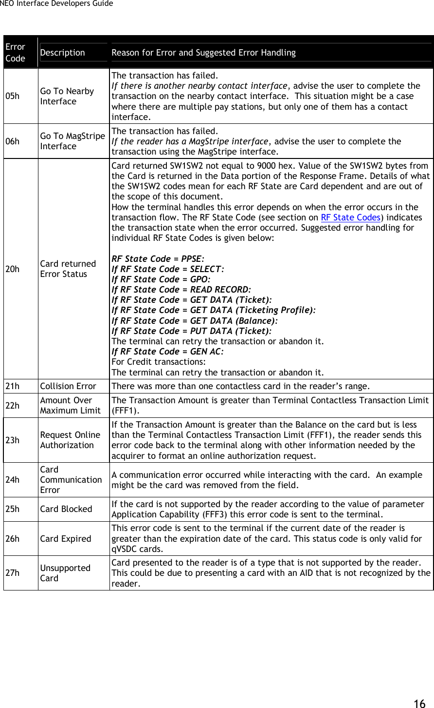
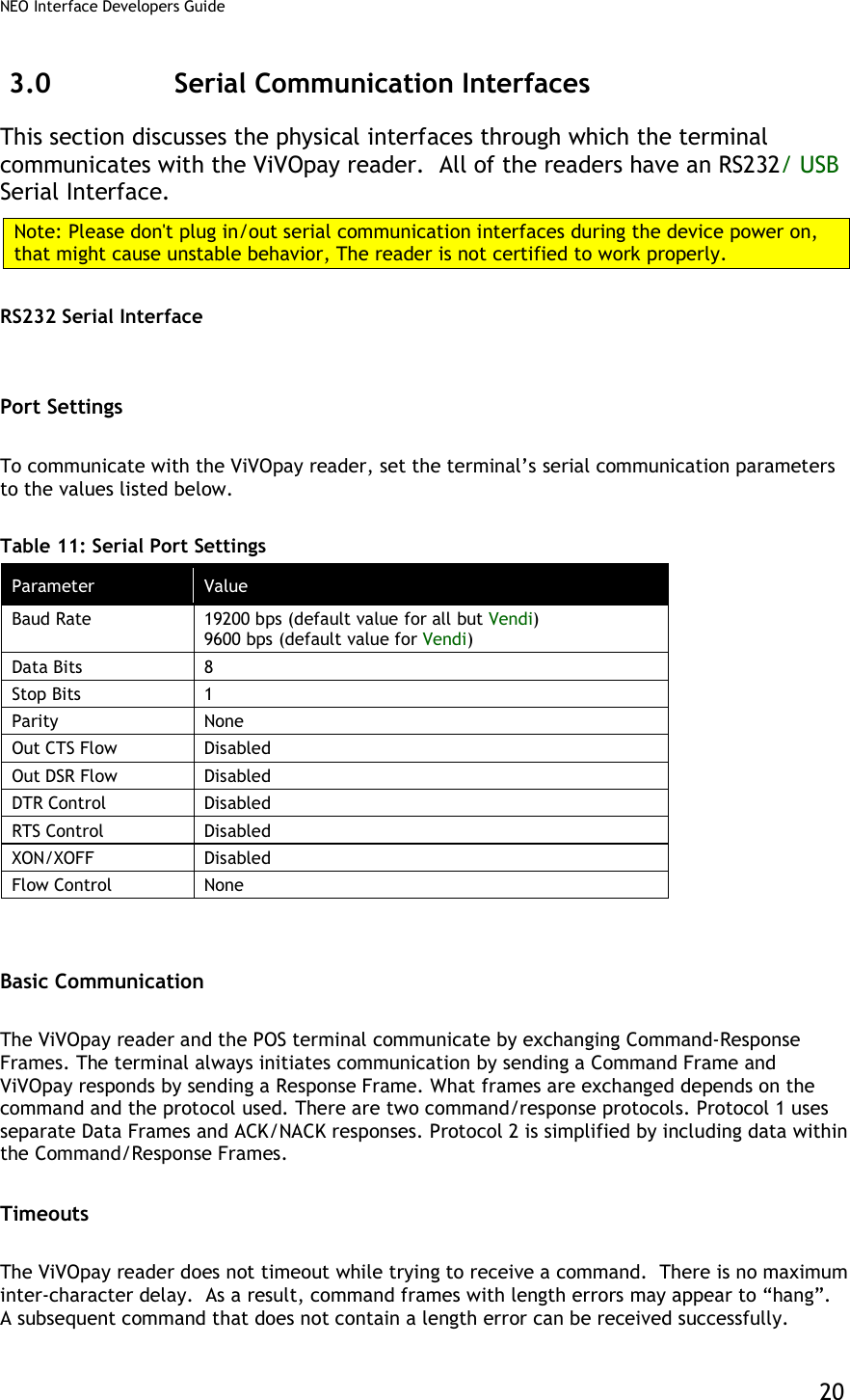
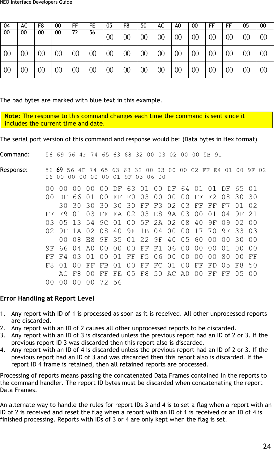
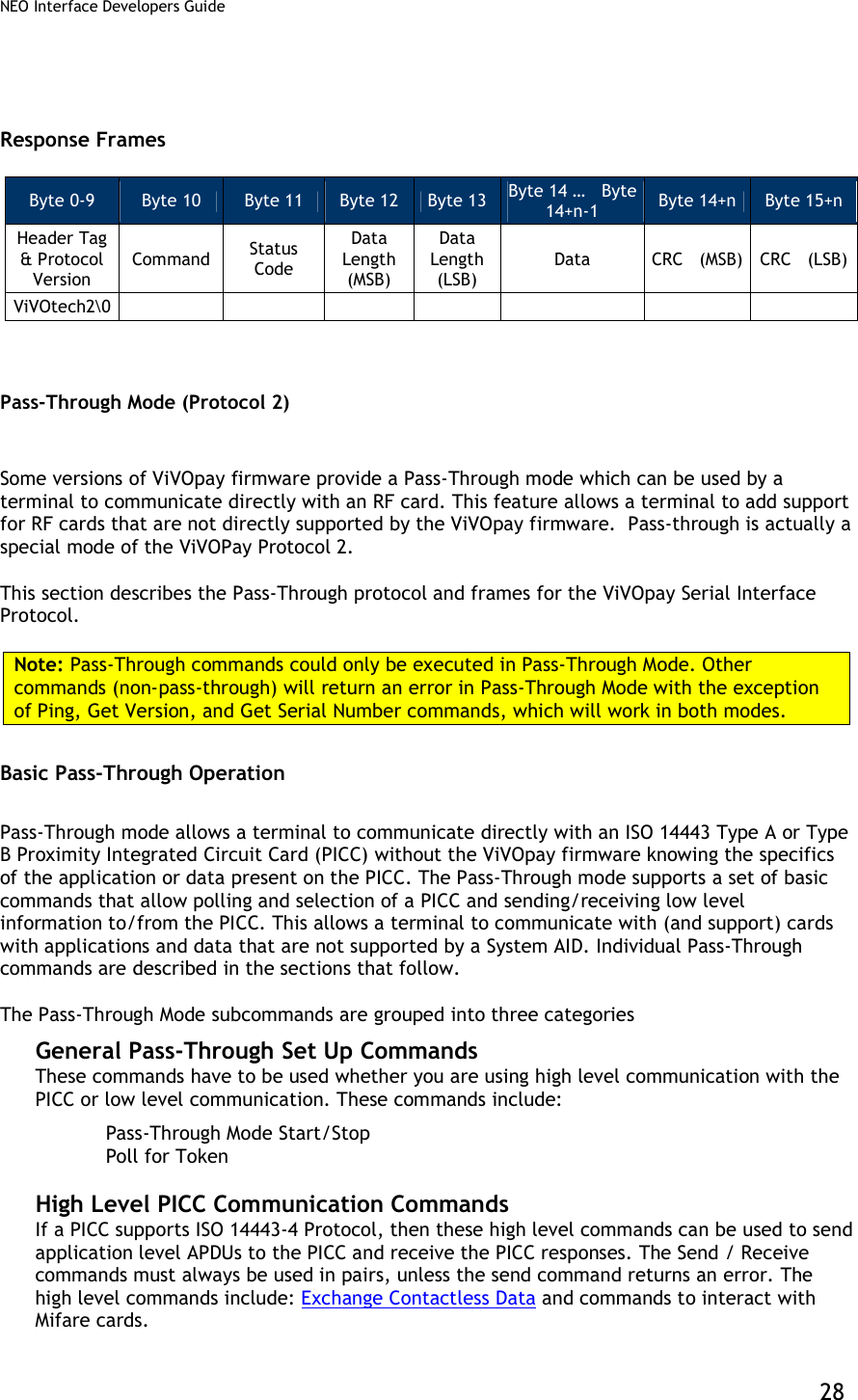
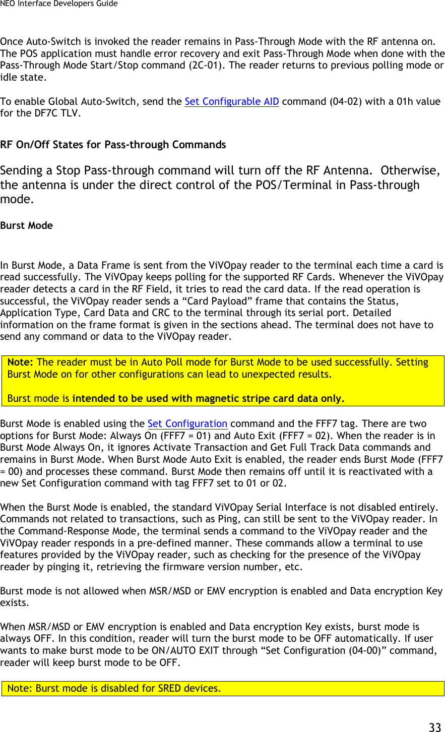
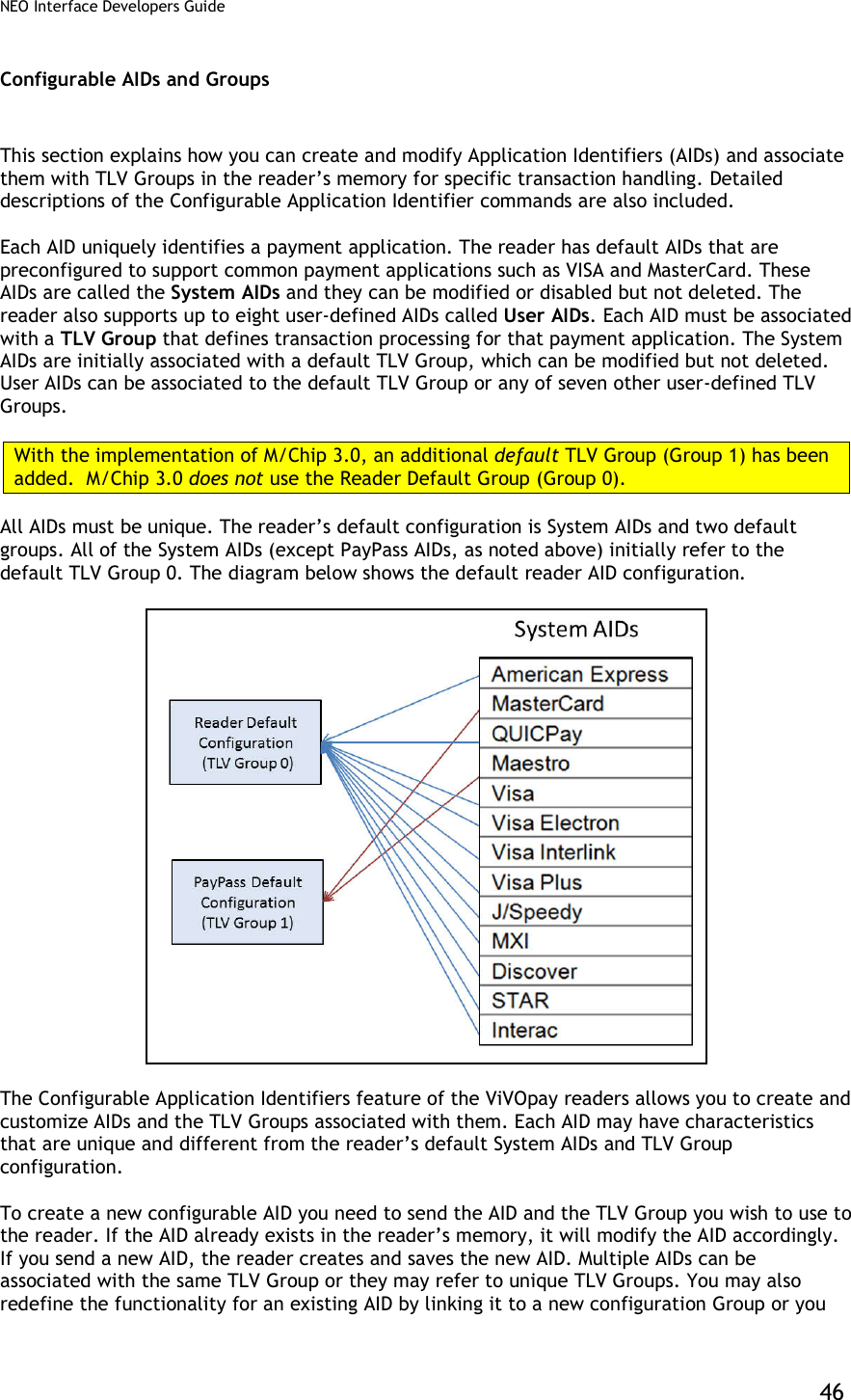
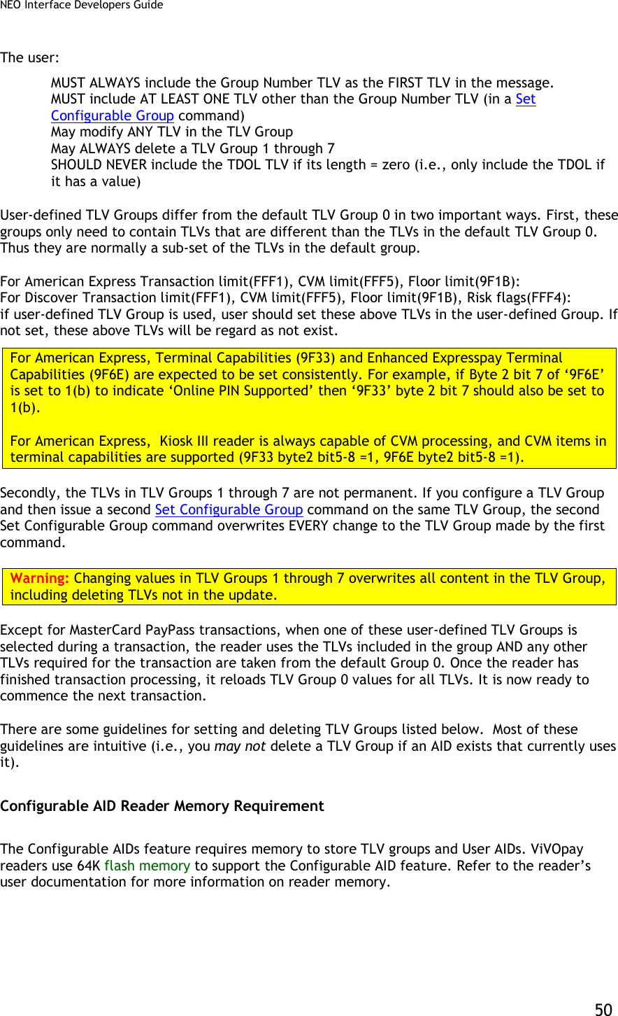
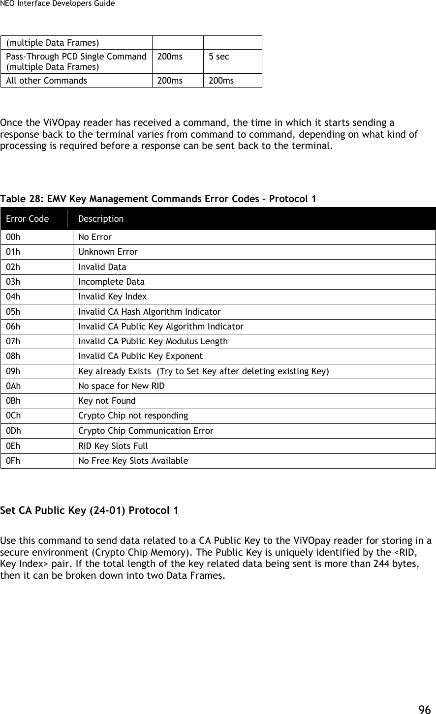
![NEO Interface Developers Guide 43 For Pass-through Frames, both Command and response frames have the CRC stored in big-endian order (MSB first). For Pass-through frames, the CRC is stored as big-endian number i.e. higher byte first. Some test values that can be used to test an implementation of this algorithm are given below. Data String (ASCII Text): 123456789 CRC: 29B1h Data (Hex): [01h] [02h] [03h] [04h] [05h] CRC: 9304h Data (Hex): [56] [69] [56] [4F] [74] [65] [63] [68] [00] [43] [18] [00] [00] [00] CRC: A1F5h The following code snippet is an example of the CRC Calculation. The returned CRC would be stored in big-endian or little-endian form, depending on whether the Protocol 1, Protocol 2 or Pass-through Mode was being used. This code has been written in Microsoft Visual C++ 6.0.](https://usermanual.wiki/ID-TECH/VP3600/User-Guide-3704675-Page-55.png)
![NEO Interface Developers Guide 44 // --------------------------------------------------------------------------------------- // ID TECH // ID TECH reserves the right to make changes without notice at any time. ID TECH makes no // warranty, expressed, implied or statutory, including but not limited to any implied // warranty of merchantability or fitness for any particular purpose, or that the use will // not infringe any third party patent, copyright or trademark. ID TECH must not be liable // for any loss or damage arising from its use. // --------------------------------------------------------------------------------------- static const unsigned short CrcTable[ 256 ] = { 0x0000, 0x1021, 0x2042, 0x3063, 0x4084, 0x50A5, 0x60C6, 0x70E7, 0x8108, 0x9129, 0xA14A, 0xB16B, 0xC18C, 0xD1AD, 0xE1CE, 0xF1EF, 0x1231, 0x0210, 0x3273, 0x2252, 0x52B5, 0x4294, 0x72F7, 0x62D6, 0x9339, 0x8318, 0xB37B, 0xA35A, 0xD3BD, 0xC39C, 0xF3FF, 0xE3DE, 0x2462, 0x3443, 0x0420, 0x1401, 0x64E6, 0x74C7, 0x44A4, 0x5485, 0xA56A, 0xB54B, 0x8528, 0x9509, 0xE5EE, 0xF5CF, 0xC5AC, 0xD58D, 0x3653, 0x2672, 0x1611, 0x0630, 0x76D7, 0x66F6, 0x5695, 0x46B4, 0xB75B, 0xA77A, 0x9719, 0x8738, 0xF7DF, 0xE7FE, 0xD79D, 0xC7BC, 0x48C4, 0x58E5, 0x6886, 0x78A7, 0x0840, 0x1861, 0x2802, 0x3823, 0xC9CC, 0xD9ED, 0xE98E, 0xF9AF, 0x8948, 0x9969, 0xA90A, 0xB92B, 0x5AF5, 0x4AD4, 0x7AB7, 0x6A96, 0x1A71, 0x0A50, 0x3A33, 0x2A12, 0xDBFD, 0xCBDC, 0xFBBF, 0xEB9E, 0x9B79, 0x8B58, 0xBB3B, 0xAB1A, 0x6CA6, 0x7C87, 0x4CE4, 0x5CC5, 0x2C22, 0x3C03, 0x0C60, 0x1C41, 0xEDAE, 0xFD8F, 0xCDEC, 0xDDCD, 0xAD2A, 0xBD0B, 0x8D68, 0x9D49, 0x7E97, 0x6EB6, 0x5ED5, 0x4EF4, 0x3E13, 0x2E32, 0x1E51, 0x0E70, 0xFF9F, 0xEFBE, 0xDFDD, 0xCFFC, 0xBF1B, 0xAF3A, 0x9F59, 0x8F78, 0x9188, 0x81A9, 0xB1CA, 0xA1EB, 0xD10C, 0xC12D, 0xF14E, 0xE16F, 0x1080, 0x00A1, 0x30C2, 0x20E3, 0x5004, 0x4025, 0x7046, 0x6067, 0x83B9, 0x9398, 0xA3FB, 0xB3DA, 0xC33D, 0xD31C, 0xE37F, 0xF35E, 0x02B1, 0x1290, 0x22F3, 0x32D2, 0x4235, 0x5214, 0x6277, 0x7256, 0xB5EA, 0xA5CB, 0x95A8, 0x8589, 0xF56E, 0xE54F, 0xD52C, 0xC50D, 0x34E2, 0x24C3, 0x14A0, 0x0481, 0x7466, 0x6447, 0x5424, 0x4405, 0xA7DB, 0xB7FA, 0x8799, 0x97B8, 0xE75F, 0xF77E, 0xC71D, 0xD73C, 0x26D3, 0x36F2, 0x0691, 0x16B0, 0x6657, 0x7676, 0x4615, 0x5634, 0xD94C, 0xC96D, 0xF90E, 0xE92F, 0x99C8, 0x89E9, 0xB98A, 0xA9AB, 0x5844, 0x4865, 0x7806, 0x6827, 0x18C0, 0x08E1, 0x3882, 0x28A3, 0xCB7D, 0xDB5C, 0xEB3F, 0xFB1E, 0x8BF9, 0x9BD8, 0xABBB, 0xBB9A, 0x4A75, 0x5A54, 0x6A37, 0x7A16, 0x0AF1, 0x1AD0, 0x2AB3, 0x3A92, 0xFD2E, 0xED0F, 0xDD6C, 0xCD4D, 0xBDAA, 0xAD8B, 0x9DE8, 0x8DC9, 0x7C26, 0x6C07, 0x5C64, 0x4C45, 0x3CA2, 0x2C83, 0x1CE0, 0x0CC1, 0xEF1F, 0xFF3E, 0xCF5D, 0xDF7C, 0xAF9B, 0xBFBA, 0x8FD9, 0x9FF8, 0x6E17, 0x7E36, 0x4E55, 0x5E74, 0x2E93, 0x3EB2, 0x0ED1, 0x1EF0 }; unsigned short CalculateCRC ( unsigned char *Buffer, unsigned int Len ) { unsigned short Crc = 0xffff; while (Len--) { Crc = CrcTable[ ((Crc >> 8) ^ *Buffer++) ] ^ (Crc << 8); } return(Crc); }](https://usermanual.wiki/ID-TECH/VP3600/User-Guide-3704675-Page-56.png)
![NEO Interface Developers Guide 52 transaction. At the end of a transaction, the reader will send any updated proprietary tags back in the Activate Response frame. Configuration Tag Tables Global Configuration Tags The following table contains TLVs that are configurable using the Set Configuration (04-00) command. These TLVs are global within in the reader. Table 19: Global Configuration TLVs Tag Data Object Name and Description Format Length (Bytes) Default Value 9A Transaction Date (YYMMDD) This value is used to set the Real Time Clock. Note: The terminal/POS application should perform range checking on this value to ensure it is within acceptable limits. n6 3 Reader Date 9F21 Transaction Time (HHMMSS) This value is used to set the Real Time Clock. Note: The terminal/POS application should perform range checking on this value to ensure it is within acceptable limits. n6 3 Reader Time DF65[1] Require Heartbeat frame to stay in Idle mode (EMEA User Experience only). If this feature is enabled, then to stay in the Idle mode, a valid frame must be received by the reader every 15 seconds or it returns to Not Working state. 00: Heartbeat frame not required 01: Heartbeat frame required b 1 00 DF66[1] Unsupported cards display option (EMEA User Experience only). If an unsupported card is detected, then display a message based on this setting. 00: Display a “Fail” message 01: Display an “Insert/ Swipe” message if the reader is configured to indicate support for Contact cards, otherwise display a “Fail” message. b 1 00 DF68 Enable/Disable Stop Command processing 0 = Disable (default) 1 = Enable b 1 00 DF6A Enable Communication Error Recovery Enables the reader to poll again and return to discovery after a communication error (e.g. tear or “no tag” error) 00: Disabled 01: Enabled (default) b 1 01](https://usermanual.wiki/ID-TECH/VP3600/User-Guide-3704675-Page-64.png)
![NEO Interface Developers Guide 53 Tag Data Object Name and Description Format Length (Bytes) Default Value DF75 Communication Error Delay time Delay between the time a communication error first occurs and the time when the reader will issue an indication of an error to the reader. If a tear occurs, but the card comes back into the field during this time, then no error indication is issued. Time is expressed in milliseconds (default is 3000ms, or 3 seconds) n (BCD) 3 00 30 00 DF7C Auto-Switch to Pass-Through Mode. Refer to Auto-Switch to Pass-Through Mode 00: Disable (default) 01: Enable b 1 00 DF7D Track 1 and Track 2 Data Format Sets the format of data returned from Activate Transaction and Get Transaction Results commands. 00: No start/end sentinels or LRC (default) 01: Add start/end sentinel and LRC b 1 00 DF7F Improved Collision Detection (see special features Improved Collision Detection.) RF signal locked to a specified card only after a specified number of polling attempts without an EMV collision. 00h = Improved Collision Detection Disabled. 02h-FFh = Number of successful polling attempts required. b 1 00 FFF3[1] Application Capability(1:Support,0:Not Support): Byte 1: (Leftmost) b8 b7 b6 b5 b4 b3 b2 b1 Meaning (0 = disable, 1 = enable) X Normal J/Speedy support X ViVOpay Mifare for NFC X Interac support X CUP support X SmartTap support X X X RFU Byte 2: b8 b7 b6 b5 b4 b3 b2 b1 Meaning (0 = disable, 1 = enable) - - - - - - - X MasterCard Credit support - - - - - - X - American Express support - - - - - X - - Visa support - - - - X - - - Mobile J/Speedy support - - - X - - - - ViVOwallet support - - X - - - - - RBS support - X - - - - - - MasterCard Cash support X - - - - - - - Discover support Example: 0009 means reader support both MasterCard and Mobile J/Speedy applications b 2 07 FF (0F FF for Kiosk III)](https://usermanual.wiki/ID-TECH/VP3600/User-Guide-3704675-Page-65.png)
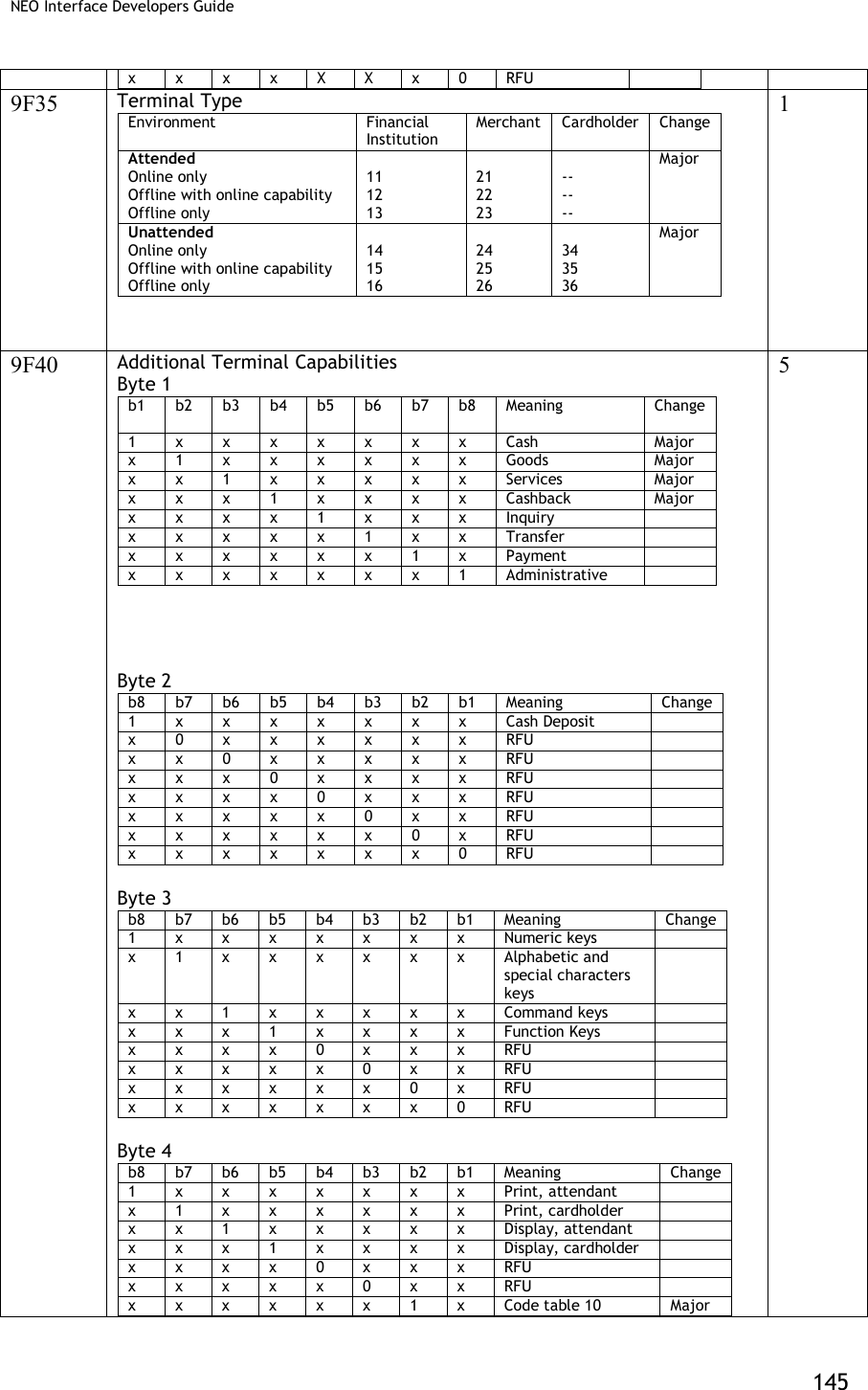
![NEO Interface Developers Guide 54 Tag Data Object Name and Description Format Length (Bytes) Default Value FFF7[1] Enable/Disable Burst Mode: Value = 00: Disable Burst Mode Value = 01: Enable Burst Mode Value = 02: Burst Mode Auto Exit. Burst mode is turned off as soon as a transaction command is received (Sections 6 and 14 of this document) b 1 02 FFF9[1] [2] [3] LCD Font Size: Value = 02: Large Value = 03: Extra Large (default) b 1 03 FFFA[1] [2] LCD delay time (ms) – default is 1000ms. If the device has no LCD, then the value will be 0. b 2 03 E8 or 00 00 FFFB[1] Language Option for LCD display: Value = 00: English only display (default) Value = 01: Chinese only display[2] Value = 02: English & Chinese display[2] Value = 03: French only display Value = 04: Other Language (if ILM present)[2] Value = 05: English & French display [4] b 1 00 DF891B Poll Mode Value = 00 : Auto-Poll Value = 01 : Poll on Demand Note: Only used for Vendi. b 1 00 9F15 Merchant Category Code Classifies the type of business being done by the merchant, see ISO 8583:1993. n4 2 00 00 9F16 Merchant Identifier ans 15 00 00 00 00 00 00 00 00 00 00 00 00 00 00 00 9F1C Terminal Identification an 8 00 00 00 00 00 00 00 00 9F40 Additional Terminal Capabilities Indicates the data input and output capabilities of the terminal. b 5 60 00 00 10 01 9F4E Merchant Name and Location Allows the reader to be configured with the Merchants Name and Location (VCPS 2.1.1 and M/Chip 3.0) ASCII <=30 00 00 00 00 00 00 00 00 00 00 00 00 00 00 00 00 00 00 00 00 00 00 00 00 00 00 00 00 00 00 9F7C Merchant Custom Data b <=20 00 00 00 00 00 00 00 00 00 00 00 00 00 00 00 00 00 00 00 00 FFF2 Interface Device Serial Number This is equivalent to tag 9F1E. They refer to the same parameter. an 8 30 30 30 30 30 30 30 30](https://usermanual.wiki/ID-TECH/VP3600/User-Guide-3704675-Page-66.png)
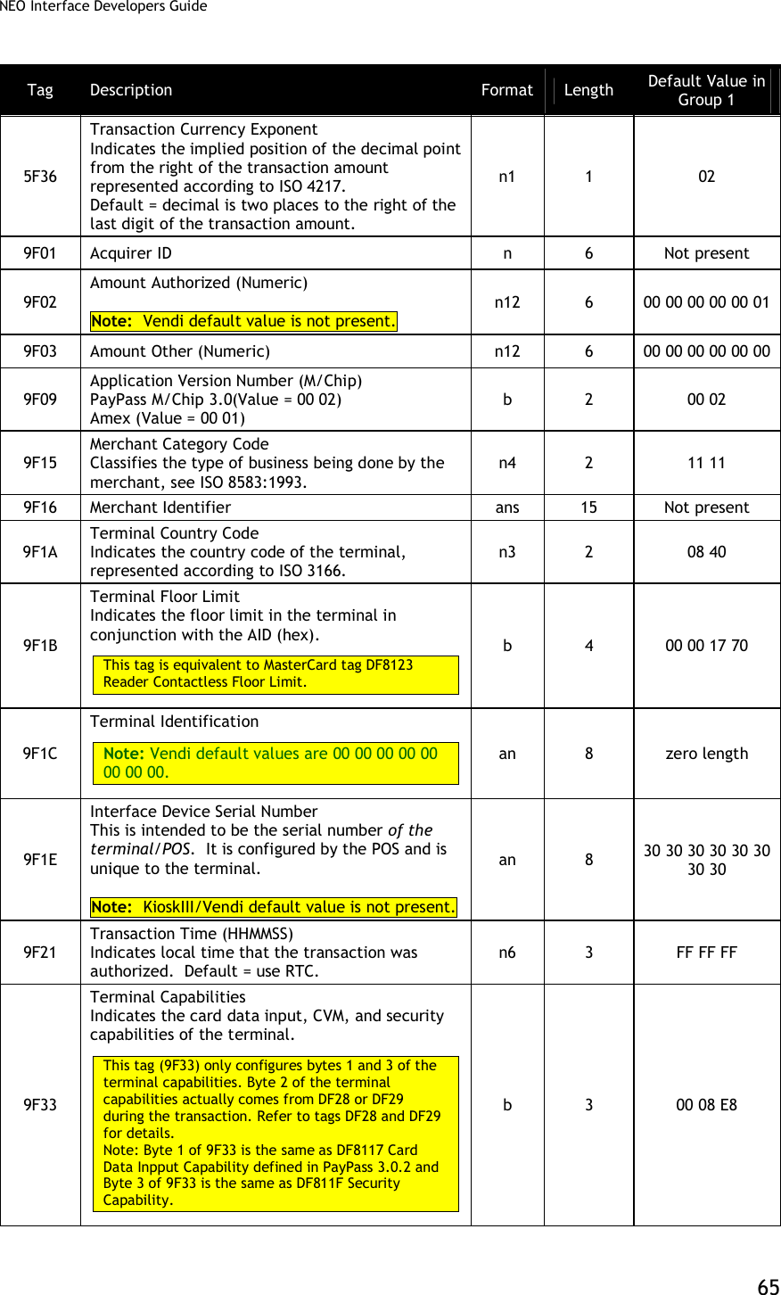
![NEO Interface Developers Guide 56 Tag Data Object Name and Description Format Length (Bytes) Default Value FFEE1E Group 0 Initialize Flag: Value = 00: not initialized.(If the tag is not found or Value is not 1, reader will initialize group 0 with default setting automatically when the power cycle is on) Value = 01: Initialized b 1 01 [1] These objects use proprietary tags. The use of these tags should be restricted to the serial interface. Once the Reader has returned an OK Response Frame, the Terminal application should dispose of the tags to avoid conflicts with other proprietary TLVs. [2] These objects only work on the ViVOpay graphic reader. [3] Only applies to non-index messages. The default size for the LCD Font is 3. The Lookup table for all the messages are hard coded with the Font Size 3. The Font Size = 2 is treated only when the three messages are displayed on the screen. When the user wants to use the LCD Font size = 2, A store LCD message command can be used to configure the string by prefixing the %F2. [4] These objects only work on the Vendi. Group Configuration Tags The following table contains tags that may be configured within a Configurable Group. For Group 0, default values exist. Except for groups associated with a PayPass AID, if a group does not define some of these TLVs, then the values in Group 0 will be used. The Set Configurable Group command should be used to set the TLVs in this section. The PayPass configuration tags are documented separately. To configure a group that will be associated with a PayPass AID, refer to PayPass Group Configuration TLVs. Table 20: Group Configuration TLVs Tag Description Format Length Default Value in Group 0 9F58 Merchant Type Indicator Provides Merchant Type Indicator used by the card for risk management. Five values are valid: 01, 02, 03, 04 and 05. (Interac) n1 1 03 9F59 Terminal Transaction Information (TTI) Provides Terminal Transaction Information for the current transaction. (Interac) Note: Vendi default values are B4 07 00. b 3 DC 80 00 9F5D Terminal Contactless Receipt Required Limit Limit Amount used to compare against Transaction amount to automatically print a transaction record. (Interac) n12 6 00 00 00 00 50 00 Only used for Kiosk III.](https://usermanual.wiki/ID-TECH/VP3600/User-Guide-3704675-Page-68.png)
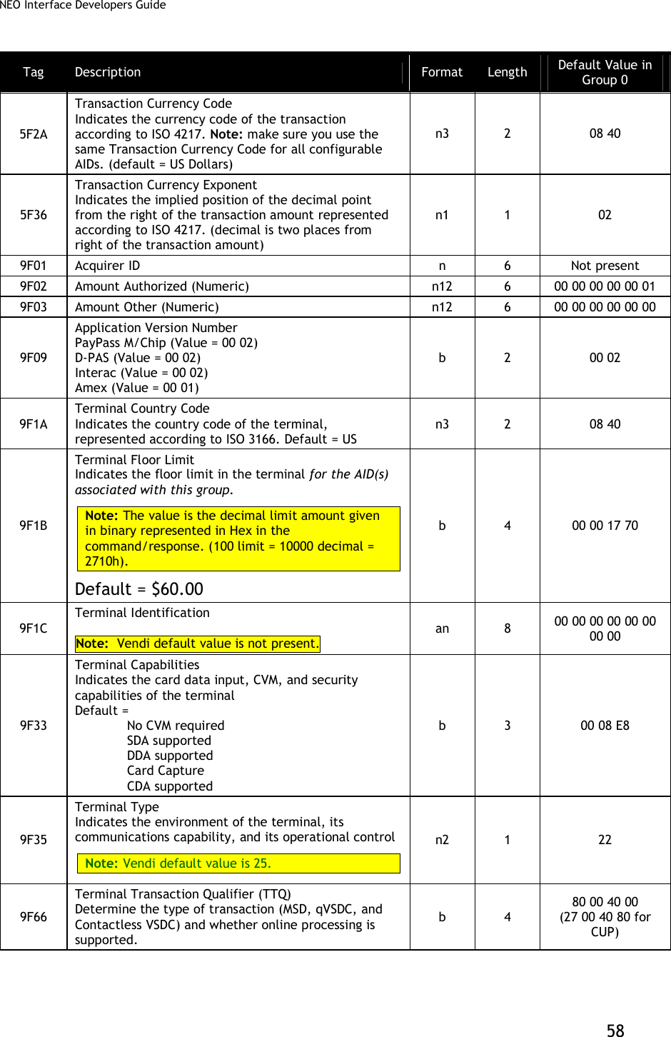
![NEO Interface Developers Guide 57 Tag Description Format Length Default Value in Group 0 9F5E Terminal Option Status Options supported by the terminal. (Interac) Note: Vendi default values are 00 00. b 2 E0 00 9F5F Terminal (Reader) Contactless Floor Limit Floor limit amount used to compare against Transaction amount. (Interac) n12 6 00 00 00 00 80 00 DF26 Enable/Disable Certificate Revocation list 0 = disable 1 = enable (default) M/Chip 3.02 can make use of the Certificate Revocation list. Note: Vendi default value is not present. b 1 01 DF2A Threshold Value for Biased Random Selection Value used in terminal risk management for random transaction selection. (Interac) n12 6 00 00 00 00 50 00 DF2B Maximum Target Percentage for Biased Random Selection Value used in terminal risk management for random transaction selection. (Interac) b 1 32 DF2C Target Percentage for Random Selection Value used in terminal risk management for random transaction selection. (Interac) b 1 0A DF51[1] ExpressPay Terminal Capabilities Used to create the ExpressPay Terminal Capabilities TLV, 9F6D for Amex ExpressPay applications. Note: Vendi default value is not present. b 1 80 DF64[1] Enable/Disable Visa Wave cards Enables the use of Visa Wave cards (not the Visa Wave protocol). 00: Reject Visa Wave cards 01: Accept Visa Wave cards b 1 00 97 Default Transaction Certificate Data Object List (TDOL) List of TLV data objects to be used by the terminal to generate the TC Hash Value in case the TDOL is not returned by the card. Note: Vendi default value is not present. In Group 0, this tag must be encapsulated in another tag, FF67. FF67 encapsulates all “variable length” tags in group 0. b <=64 Zero length 9C Transaction Type Indicates the type of financial transaction, represented by the first two digits of ISO 8583:1987 Processing Code. (default = purchase goods or services) n2 1 00](https://usermanual.wiki/ID-TECH/VP3600/User-Guide-3704675-Page-69.png)
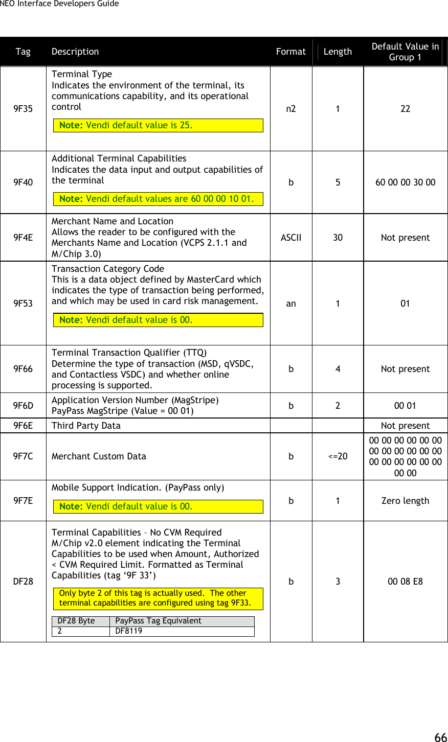
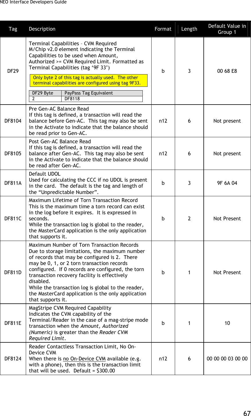
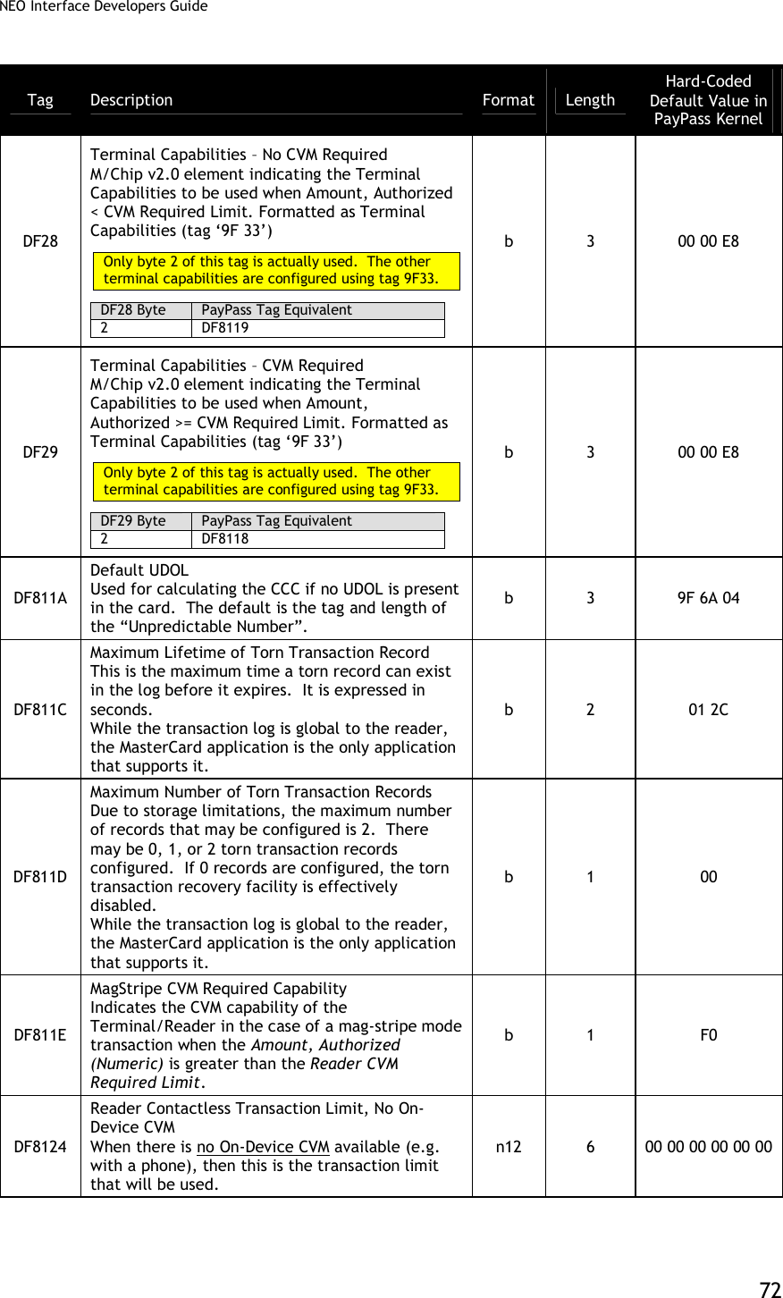
![NEO Interface Developers Guide 59 Tag Description Format Length Default Value in Group 0 9F6D Application Version Number (MagStripe) PayPass MagStripe (Value = 00 01) Note: Vendi default value is not present. b 2 00 01 DF28 Terminal Capabilities – No CVM Required M/Chip v2.0 element indicating the Terminal Capabilities to be used when Amount, Authorized < CVM Required Limit. Formatted as Terminal Capabilities (tag ‘9F 33’) Only byte 2 of this tag is actually used. The other terminal capabilities are configured using tag 9F33. Note: Vendi default value is not present. DF28 Byte PayPass Tag Equivalent 2 DF8119 b 3 00 08 E8 DF29 Terminal Capabilities – CVM Required M/Chip v2.0 element indicating the Terminal Capabilities to be used when Amount, Authorized >= CVM Required Limit. Formatted as Terminal Capabilities (tag ‘9F 33’) Only byte 2 of this tag is actually used. The other terminal capabilities are configured using tag 9F33. Note: Vendi default value is not present. DF29 Byte PayPass Tag Equivalent 2 DF8118 b 3 00 68 E8 FFE4[1] Group Number The group number assigned to this group of parameters. AIDs may be associated with the group number. This tag is mandatory when getting or setting group parameters and it must be the 1st TLV in Data Field. It is used as the “key” for the group parameter set. n2 1 -- FFF1[1] Terminal Contactless Transaction Limit Indicates the terminal limit for this AID for Contactless transactions. n12 6 00 00 00 01 00 00](https://usermanual.wiki/ID-TECH/VP3600/User-Guide-3704675-Page-71.png)
![NEO Interface Developers Guide 60 Tag Description Format Length Default Value in Group 0 FFF4[1] Visa Reader Risk Flags Byte 1 b8 b7 b6 b5 b4 b3 b2 b1 Meaning (0 = disable, 1 = enable) - - - - - - - X Status Check X X X X X X X - RFU Byte 2: b8 b7 b6 b5 b4 b3 b2 b1 Meaning (0 = disable, 1 = enable) - - - - - - - X Transaction Limit Check - - - - - - X - CVM Required Limit Test - - - - - X - - Terminal Floor Limit Check - - - - X - - - Cash Transaction Reader Risk (RR) - - - X - - - - Cashback Reader Risk (RR) - - X - - - - - DRL (Dynamic Reader Limits) RR X X - - - - - - RFU Byte 3 b8 b7 b6 b5 b4 b3 b2 b1 Meaning (0 = disable, 1 = enable) - - - - - - - X 1 = online cryptogram required for zero amount (only used with zero amount check enabled) - - - - - - X - 1 = perform zero amount check X X X X X X - - RFU For example: 0x00 = Zero Amount check disabled. 0x01 = Zero Amount check is disabled and online cryptogram required bit will not be checked. (default) 0x02 = Zero Amount check enabled. 0x03 = Zero Amount check enabled and Option 1, online Cryptogram Required Note: Vendi default values are 01 00 01. b 3 00 06 01](https://usermanual.wiki/ID-TECH/VP3600/User-Guide-3704675-Page-72.png)
![NEO Interface Developers Guide 61 Tag Description Format Length Default Value in Group 0 D-PAS Reader Risk Flags: Byte 1 b8 b7 b6 b5 b4 b3 b2 b1 Meaning (0 = disable, 1 = enable) - - - - - - - X RFU X 1=Status Check Support X X X X X X - RFU Byte 2: b8 b7 b6 b5 b4 b3 b2 b1 Meaning (0 = disable, 1 = enable) X X X X X X X X RFU Byte 3 b8 b7 b6 b5 b4 b3 b2 b1 Meaning (0 = disable, 1 = enable) - - - - - - - X 1 = online cryptogram required for zero amount X X X X X X X - RFU b 3 FFF5[1] CVM Required Limit Indicates the CVM required limit in the terminal for the associated AIDs. n12 6 00 00 00 00 80 00 FFFC[1] PayPass Profile (also used for Amex) Information in this tag is equivalent to PayPass tag DF811B, although it is formatted slightly differently: 87654321 Bit Meaning Value -------X MagStripe Only 0 = normal transaction 1 = MagStripe only transaction allowed ------X- M/Chip Only 0 = normal transaction 1 = M/Chip only transaction allowed -----X-- On Device CVM 0 = not supported 1 = supported XXXXX--- RFU The default value is 0x01 – support MagStripe only. Note: Vendi default value is not present. b 1 01 FFFD[1] Terminal Action Code (Online) Reflect the acquirer-selected action to be taken upon analysis of the TVR. b 5 F8 50 AC F8 00 FFFE[1] Terminal Action Code (Default) Reflect the acquirer-selected action to be taken upon analysis of the TVR. b 5 F8 50 AC A0 00 FFFF[1] Terminal Action Code (Denial) Reflect the acquirer-selected action to be taken upon analysis of the TVR. b 5 00 00 00 00 00](https://usermanual.wiki/ID-TECH/VP3600/User-Guide-3704675-Page-73.png)
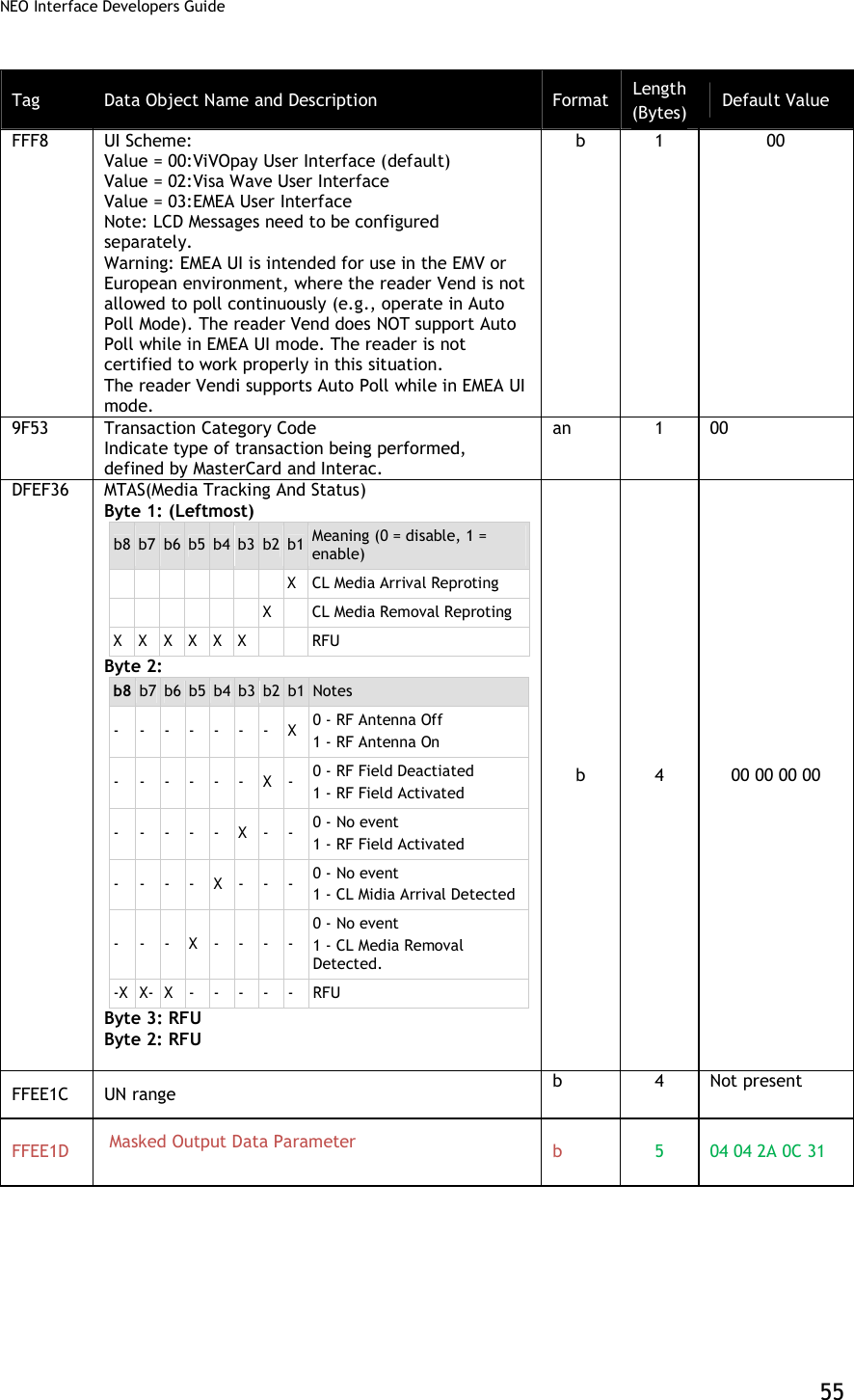
![NEO Interface Developers Guide 62 Tag Description Format Length Default Value in Group 0 FFF0[1] Specific Feature Switch Used with Visa VCPS 2.1.1/2.1.2. It controls Visa CVN17 support and Track 1 & 2 data in the transaction response. Byte 1 b8 b7 b6 b5 b4 b3 b2 b1 - - - - - - - X RFU (Deprecated) - - - - - - X - 1 = Visa CVN17 supported 0 = Visa CVN17 disabled - - - - - X - - 1 = Remove Track 1 data in Visa response - - - - X - - - 1 = Remove Track 2 data in Visa response X X X X - - - - RFU Byte 2: RFU Byte 3: RFU b 3 02 00 00 9F5A Terminal Transaction Type (Interac) • 0x00 = Purchase • 0x01 = Refund b 1 00 FFEE1D Masked Output Data Parameter When there is a PAN to be output in masked format, this parameter gives the key points of the format. Byte 1: PrePAN, value scope is [0, 6], Byte 2: PosPAN, value scope is [0, 4], Byte 3: MaskAscii, value scope is [20h, 7Eh], Byte 4: MaskHex, value scope is [0Ah, 0Fh] Byte 5: Expire date output option, 0x30=Mask, 0x31=NotMask, default 0x31 For detailed rules, please refer to "ID-Tech Encypt Data Format In Command / Response Specification for ICC Communication". b 5 04 04 2A 0C 31 9F41 Counter maintained by the terminal that is incremented by one for each transaction Note: Vendi default value is not present. n 4 4 Not Present DF891C “Interac Retry Limit” Configured value for the total number of tap attempts during an Interac Mobile Debit (NFC) application transaction. Note: Vendi default value is not present. n1 1 Not Present](https://usermanual.wiki/ID-TECH/VP3600/User-Guide-3704675-Page-74.png)
![NEO Interface Developers Guide 63 Tag Description Format Length Default Value in Group 0 DFEF2F CUP Risk and Configuration Flag Byte 1 b8 b7 b6 b5 b4 b3 b2 b1 - - - - - - - X Status Check - - - - - - X - Transaction Limit Check - - - - - X - - CVM required Limit Check - - - - X - - - Terminal Floor Limit Check - - - X - - - - Zero Amount Check X X X - - - - - RFU Byte 2: b8 b7 b6 b5 b4 b3 b2 b1 - - - - - - - X RFU - - - - - - X - Exception File Support - - - - X X - - RFU - - - X - - - - Online Authentication Support - - X - - - - - RFU - X - - - - - - UPI Support X - - - - - - - Cardholder Credential Support Byte 3: b8 b7 b6 b5 b4 b3 b2 b1 - - - - - - - X Encrypt Keyboard Support - - - - - - X - Reversal Support - - - - - X - - qUICS Online ODA Fail Decision: 1 = Go Online 0 = Decline X X X X X - - - RFU Byte 4: RFU b 4 Not Present DFEE3F Default TDOL b var Not Present [1] These objects use proprietary tags. The use of these tags should be restricted to the serial interface. Once the Reader has returned an OK Response Frame, the Terminal application should dispose of the tags to avoid conflicts with other proprietary TLVs. [2] Not used by M/Chip 3.0 because M/Chip 3.0 redefines this as a card tag that passes Application Capability Information. [3] These objects only work on the Vendi. [4] These objects only work on the ViVOpay graphic reader.](https://usermanual.wiki/ID-TECH/VP3600/User-Guide-3704675-Page-75.png)
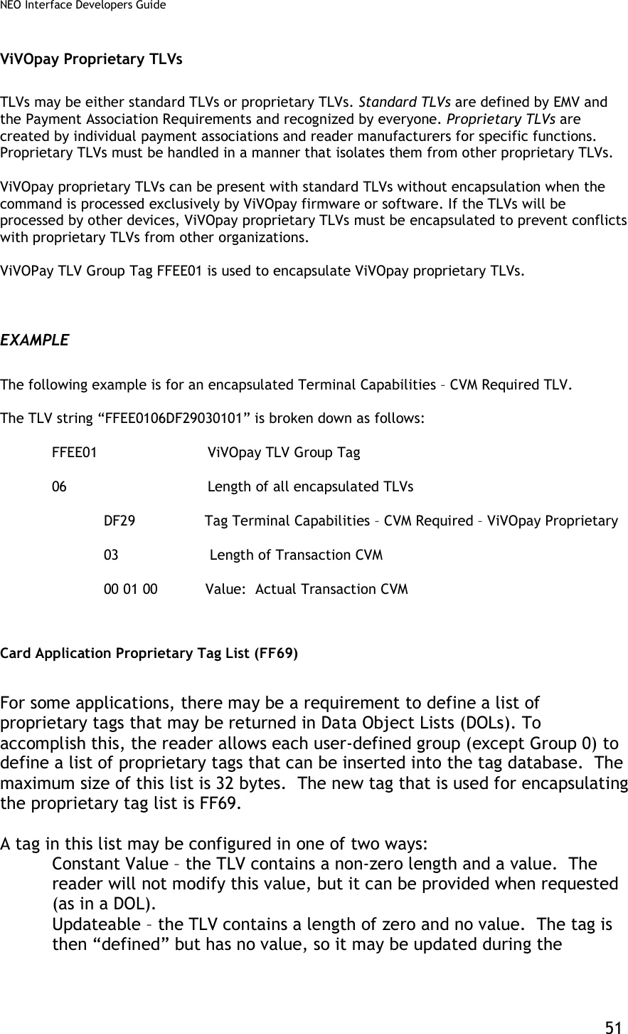
![NEO Interface Developers Guide 68 Tag Description Format Length Default Value in Group 1 DF8125 Reader Contactless Transaction Limit, On-Device CVM When On-Device CVM is available (e.g. with a phone) then this is the transaction limit that will be used. Note: Vendi default values are 00 00 00 03 00 00. KioskIII default values are 00 00 00 05 00 00. n12 6 Not Present DF812C MagStripe No CVM Required Capability Indicates the CVM capability of the Terminal/Reader in the case of a mag-stripe mode transaction when the Amount, Authorized (Numeric) is less than or equal to the Reader CVM Required Limit. b 1 00 DF812D Message Hold Time Indicates the default delay for the processing of the next MSG signal. The Message Hold Time is an integer in units of 100ms. While this value is configurable, it is not used in practice in the reader. It is a MasterCard requirement. n6 3 Not Present DF8130 RF Hold Time Value Indicates the time that the field is to be turned off after the transaction is completed if requested to do so by the cardholder device. The Hold Time Value is in units of 100ms. While this value is configurable, it is not used in practice in the reader. It is a MasterCard requirement. b 1 Not Present DF8131 Phone Message Table Defines for the selected AID the message and status identifiers as a function of the POS Cardholder Interaction Information. The Phone Message Table is a variable length list with 8-byte entries. Each entry in the Phone Message Table contains the following fields: PCII Mask (3 bytes, binary) PCII Value (3 bytes, binary) Message Identifier (1 byte, binary) Status (1 byte, binary) The last entry in the phone message table must always have the PCII Mask and PCII Value set to ‘000000’. B Var No Present FF69 Proprietary Tag List Proprietary tags that are not otherwise configured may be configured by encapsulating them in this tag list. b <=32 Not present FFE4[1] Group Number The group number that contains the characteristics for this AID This tag is mandatory when getting or setting group parameters and it must be the 1st TLV in Data Field. n2 1 --](https://usermanual.wiki/ID-TECH/VP3600/User-Guide-3704675-Page-80.png)
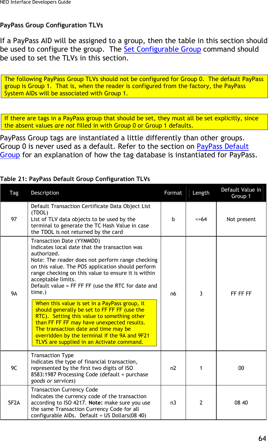
![NEO Interface Developers Guide 69 Tag Description Format Length Default Value in Group 1 FFF1[1] Terminal Contactless Transaction Limit Indicates the terminal limit for this AID for Contactless transactions. n12 6 00 00 00 01 00 00 FFF5[1] CVM Required Limit Indicates the CVM required limit in the terminal for the associated AIDs. Default = $80.00 This is equivalent to MasterCard tag DF8126. n12 6 00 00 00 00 80 00 FFF8[1] UI Scheme: Value = 00:ViVOpay User Interface (default) Value = 02:Visa Wave User Interface Value = 03:EMEA User Interface Note: LCD Messages need to be configured separately. Warning: EMEA UI is intended for use in the EMV or European environment, where the reader is not allowed to poll continuously (e.g., operate in Auto Poll Mode). The reader does NOT support Auto Poll while in EMEA UI mode. The reader is not certified to work properly in this situation. Note: Vendi default value is not present. For PayPass M/Chip, this value should be set to 03 (EMEA). It defaults to ViVOpay for backward compatibility with MagStripe applications. b 1 00 FFFB[1] Language Option for LCD display: Value = 00: English only display (default) Value = 01: Chinese only display[2] Value = 02: English & Chinese display[2] Value = 03: French only display Value = 04: Other Language (if ILM present)[2] Value = 05: English & French display [3] Note: Vendi default value is not present. b 1 00 FFFC[1] PayPass Profile Information in this tag is equivalent to PayPass tag DF811B, although it is formatted slightly differently: 87654321 Bit Meaning Values -------X MagStripe Only 0 = normal transaction 1 = MagStripe only transactions allowed ------X- M/Chip Only 0 = normal transaction 1 = M/Chip only Transactions allowed -----X-- On Device CVM 0 = not supported 1 = supported XXXXX--- RFU The default value is 0x01 – support MagStripe only. b 1 01](https://usermanual.wiki/ID-TECH/VP3600/User-Guide-3704675-Page-81.png)
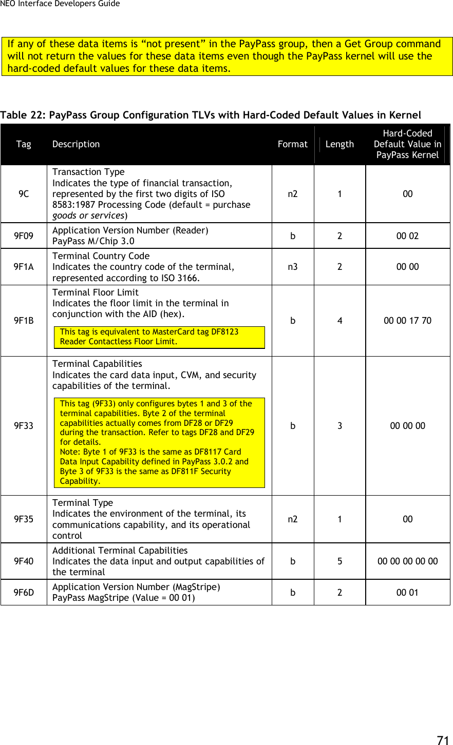
![NEO Interface Developers Guide 70 Tag Description Format Length Default Value in Group 1 FFFD[1] Terminal Action Code (Online) Reflect the acquirer-selected action to be taken upon analysis of the TVR. This is equivalent to MasterCard tag DF8122. b 5 F8 50 AC F8 00 FFFE[1] Terminal Action Code (Default) Reflect the acquirer-selected action to be taken upon analysis of the TVR. This is equivalent to MasterCard tag DF8120. b 5 F8 50 AC A0 00 FFFF[1] Terminal Action Code (Denial) Reflect the acquirer-selected action to be taken upon analysis of the TVR. This is equivalent to MasterCard tag DF8121. b 5 00 00 00 00 00 FFF2 Interface Device Serial Number This is equivalent to tag 9F1E. They refer to the same parameter. an 8 30 30 30 30 30 30 30 30 [1] These objects use proprietary tags. The use of these tags should be restricted to the serial interface. Once the Reader has returned an OK Response Frame, the Terminal application should dispose of the tags to avoid conflicts with other proprietary TLVs. [2] These objects only work on the ViVOpay graphic reader. [3] These objects only work on the Vendi PayPass Group Configuration TLVs with Hard-Coded Values in Kernel PayPass transactions do not use Group 0 at all. If a TLV data item has not been defined in a PayPass group (Group 1 or higher), then the default value is not picked up from Group 0 as for other card types. There is a minimal sub-set of TLV data items that must be present for a PayPass transaction to be performed. If any of the data items from this sub-set are not present, a PayPass transaction cannot be performed. To allow PayPass transactions to be performed even if these critical data items are missing from the PayPass group, The PayPass Kernel keeps a set of hard-coded default values for these data items. If any of these data items are not present in the PayPass Group then the kernel uses the hard-coded value for the missing data item. A list of data items that have a hard-coded value and the default value are given in the following table.](https://usermanual.wiki/ID-TECH/VP3600/User-Guide-3704675-Page-82.png)
![NEO Interface Developers Guide 73 Tag Description Format Length Hard-Coded Default Value in PayPass Kernel DF8125 Reader Contactless Transaction Limit, On-Device CVM When On-Device CVM is available (e.g. with a phone) then this is the transaction limit that will be used. n12 6 00 00 00 00 00 00 DF812C MagStripe No CVM Required Capability Indicates the CVM capability of the Terminal/Reader in the case of a mag-stripe mode transaction when the Amount, Authorized (Numeric) is less than or equal to the Reader CVM Required Limit. b 1 F0 DF812D Message Hold Time Indicates the default delay for the processing of the next MSG signal. The Message Hold Time is an integer in units of 100ms. While this value is configurable, it is not used in practice in the reader. It is a MasterCard requirement. n6 3 00 00 13 DF8130 RF Hold Time Value Indicates the time that the field is to be turned off after the transaction is completed if requested to do so by the cardholder device. The Hold Time Value is in units of 100ms. While this value is configurable, it is not used in practice in the reader. It is a MasterCard requirement. b 1 0D DF8131 Phone Message Table Defines for the selected AID the message and status identifiers as a function of the POS Cardholder Interaction Information. The Phone Message Table is a variable length list with 8-byte entries. Each entry in the Phone Message Table contains the following fields: PCII Mask (3 bytes, binary) PCII Value (3 bytes, binary) Message Identifier (1 byte, binary) Status (1 byte, binary) The last entry in the phone message table must always have the PCII Mask and PCII Value set to ‘000000’. b Var. See next table ‘Phone Message Table Hard-Coded Default Value in Kernel’. FFF5[1] CVM Required Limit Indicates the CVM required limit in the terminal for the associated AIDs. This is equivalent to MasterCard tag DF8126. n12 6 00 00 00 00 00 00](https://usermanual.wiki/ID-TECH/VP3600/User-Guide-3704675-Page-85.png)
![NEO Interface Developers Guide 74 Tag Description Format Length Hard-Coded Default Value in PayPass Kernel FFFC[1] PayPass Profile Information in this tag is equivalent to PayPass tag DF811B, although it is formatted slightly differently: 87654321 Bit Meaning Values -------X MagStripe Only 0 = normal transaction 1 = MagStripe only transactions allowed ------X- M/Chip Only 0 = normal transaction 1 = M/Chip only Transactions allowed -----X-- On Device CVM 0 = not supported 1 = supported XXXXX--- RFU b 1 00 FFFD[1] Terminal Action Code (Online) Reflect the acquirer-selected action to be taken upon analysis of the TVR. This is equivalent to MasterCard tag DF8122. b 5 CC 00 00 00 00 FFFE[1] Terminal Action Code (Default) Reflect the acquirer-selected action to be taken upon analysis of the TVR. This is equivalent to MasterCard tag DF8120. b 5 CC 00 00 00 00 FFFF[1] Terminal Action Code (Denial) Reflect the acquirer-selected action to be taken upon analysis of the TVR. This is equivalent to MasterCard tag DF8121. b 5 00 00 00 00 00 [1] These objects use proprietary tags. The use of these tags should be restricted to the serial interface. Once the Reader has returned an OK Response Frame, the Terminal application should dispose of the tags to avoid conflicts with other proprietary TLVs. Table 23: Phone Message Table – Hard-Coded Default Value in Kernel PCI Mask PCII Value Message Identifier Status 000800 000800 20 (SEE PHONE) 00 (NOT READY) 000400 000400 20 (SEE PHONE) 00 (NOT READY) 000100 000100 20 (SEE PHONE) 00 (NOT READY) 000200 000200 20 (SEE PHONE) 00 (NOT READY) 000000 000000 20 (SEE PHONE) 00 (NOT READY)](https://usermanual.wiki/ID-TECH/VP3600/User-Guide-3704675-Page-86.png)
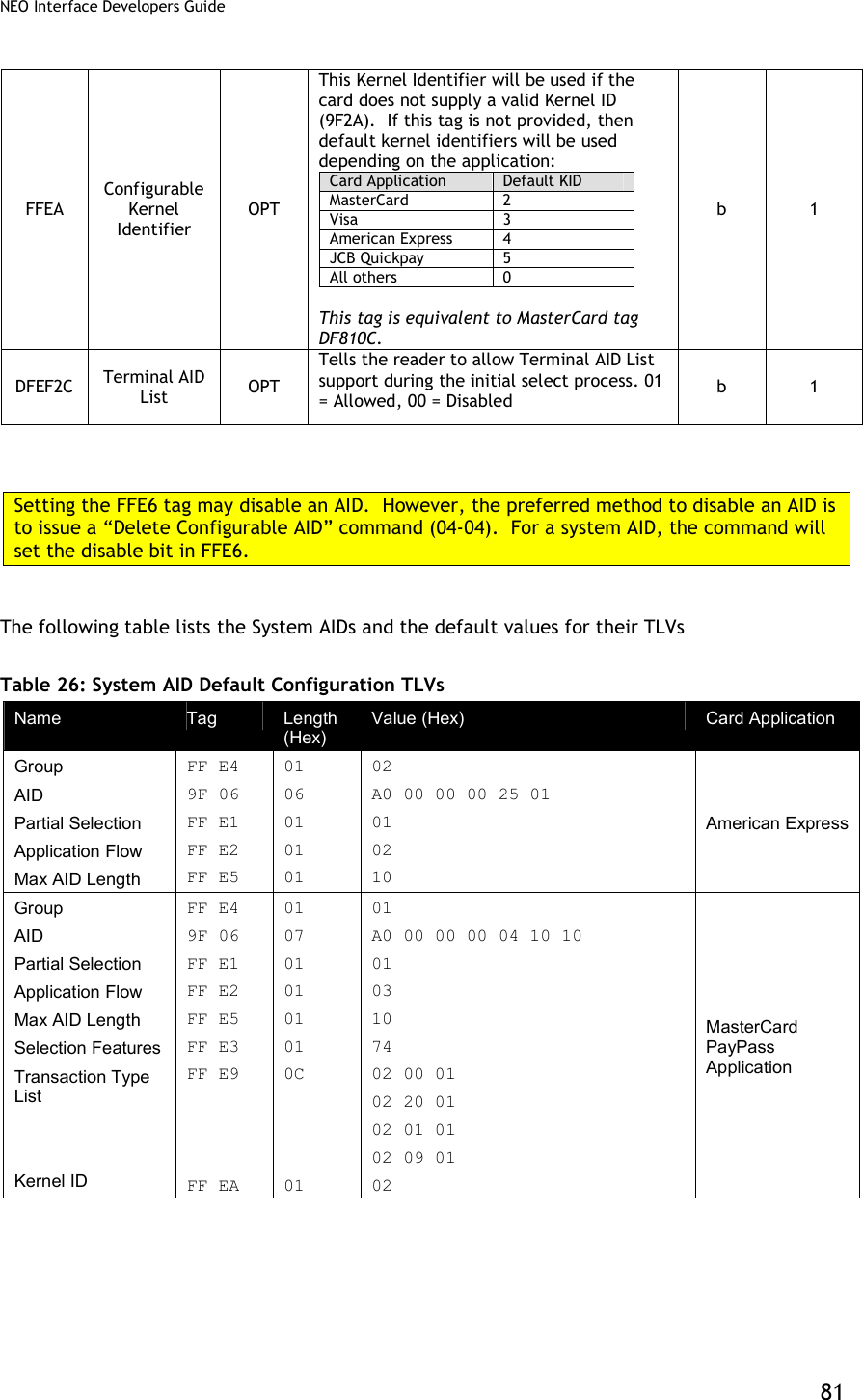
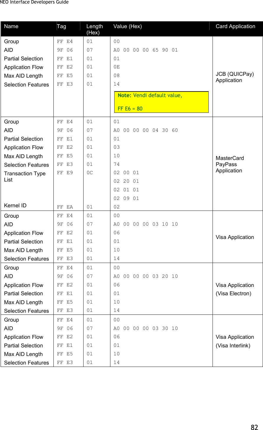
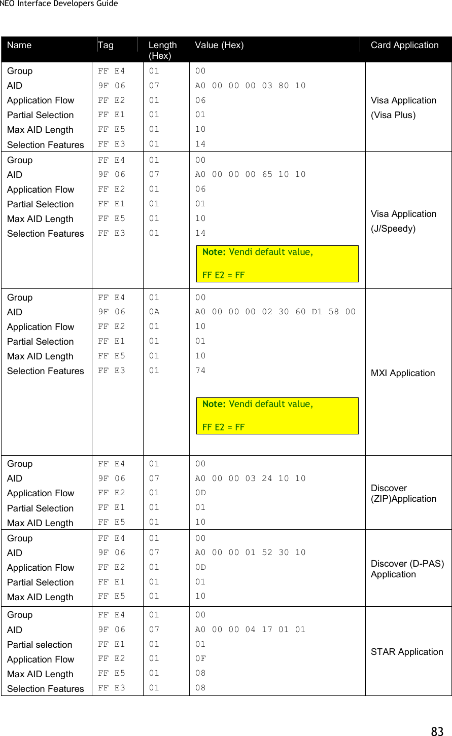
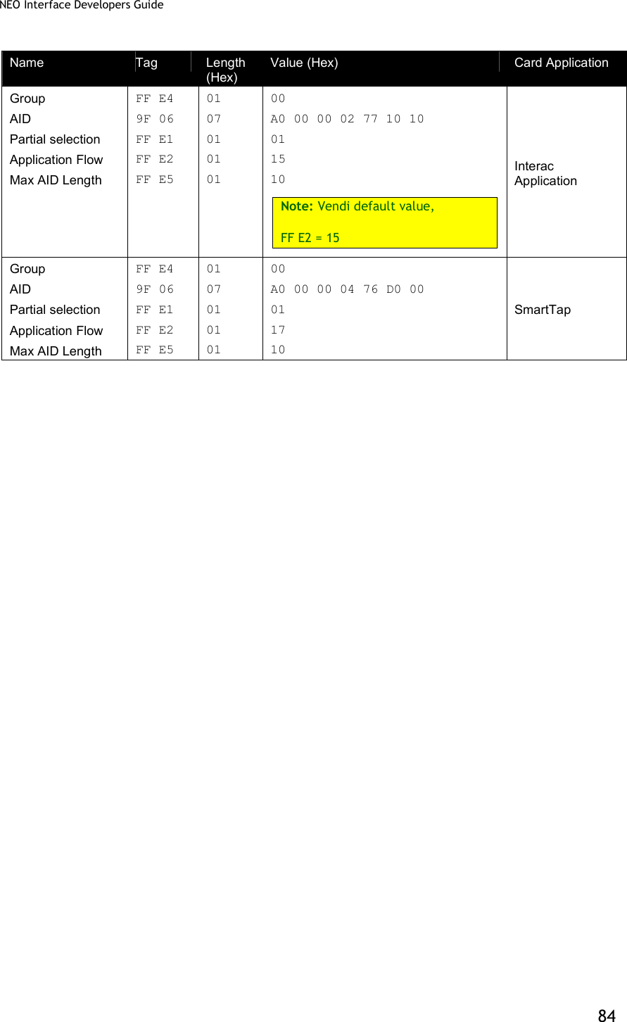
![NEO Interface Developers Guide 78 Tag Description Format Length Default Value in Group 2 FFF1[1] Terminal Contactless Transaction Limit Indicates the terminal limit for this AID for Contactless transactions. Note: Kiosk III default value is 00 00 00 01 00 00 n12 6 00 00 00 01 50 00 FFF5[1] CVM Required Limit Indicates the CVM required limit in the terminal for the associated AIDs. Note: Kiosk III default value is 00 00 00 00 80 00 n12 6 00 00 00 00 50 00 FFFD[1] Terminal Action Code (Online) Reflect the acquirer-selected action to be taken upon analysis of the TVR. Note: Kiosk III default value is F8 50 AC F8 00 b 5 00 00 00 00 00 FFFE[1] Terminal Action Code (Default) Reflect the acquirer-selected action to be taken upon analysis of the TVR. Note: KioskIII default value is F8 50 AC A0 00 b 5 00 00 00 00 00 FFFF[1] Terminal Action Code (Denial) Reflect the acquirer-selected action to be taken upon analysis of the TVR. b 5 00 00 00 00 00 [1] These objects use proprietary tags. The use of these tags should be restricted to the serial interface. Once the Reader has returned an OK Response Frame, the Terminal application should dispose of the tags to avoid conflicts with other proprietary TLVs. [2] These objects only work on the ViVOpay graphic reader. [3] These objects only work on the Vendi AID Configuration Tags In this table, the “Usage” column indicates when the tag is used. In some cases, the use may depend on whether a system AID or a user AID is being configured. The possible usages are: MAND – this is a mandatory tag when configuring an AID OPT – this is an optional tag when configuring an AID NEVER – this tag should never be used for configuring this type of AID (e.g. “System”) DEP – this tag is Mandatory depending on how another tag is configured. For default values of the AID configuration TLVs for each System AID, refer to the System AID Default Configuration TLVs table in the appendix.](https://usermanual.wiki/ID-TECH/VP3600/User-Guide-3704675-Page-90.png)
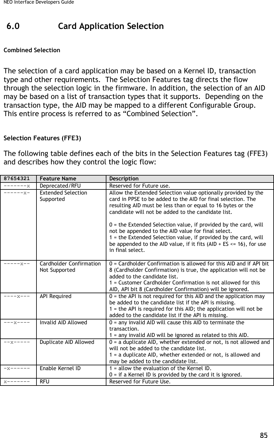
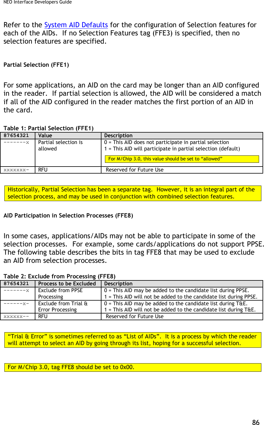
![NEO Interface Developers Guide 79 Table 25: AID Configuration TLVs Tag Data Object Name Usage Description Format Length 9F06 Application Identifier (AID) MAND Identifies the application as described in ISO/IEC 7816-5. This must be the 2nd TLV in the data field. b 5 – 16 DF7C Auto-Switch OPT Automatically switch to Pass-Through Mode when PICC is unknown. 00h = disabled (default) 01h = enabled b 1 FFE0[1] Registered Application Provider Identifier (RID) Sys = NEVER User = OPT Identifies the payment system to which the Certification Authority Public Key is associated. If this Tag is not provided the first five bytes from the AID are used. b 5 FFE1[1] Partial Selection Allowed OPT (Visa MAND) Tells the reader to allow partial selection during the initial select process. 01 = Allowed, 00 = Disabled Note: Required for Visa application flow, this value is set to 01 Allowed and cannot be changed. b 1 FFE2[1] Application Flow Sys = NEVER User = MAND 1 (01h) – MasterCard MagStripe Application 2 (02h) – American Express Application 3 (03h) – MasterCard PayPass Application 6 (06h) - Visa Application. 13 (0Dh) - Discover Application 14 (0Eh) – JCB QuicPay Application 15 (0Fh) – STAR Application 21 (15h) –Interac Application 23 (17h) –SmartTap b 1 FFE3 Selection Features OPT Enables or disables selection features. For M/Chip 3.0, this value will default to 74h. Please refer to the Selection Features section for a detailed description of this tag. 87654321 Selection Feature -------x Deprecated / RFU ------x- Extended Selection Supported -----x-- Cardholder Confirmation Not Supported ----x--- API (application priority indicator) required ---x---- Invalid AID Allowed --x----- Duplicate AID Allowed -x------ Enable Kernel ID x------- RFU b 1](https://usermanual.wiki/ID-TECH/VP3600/User-Guide-3704675-Page-91.png)
![NEO Interface Developers Guide 80 FFE4[1] TLV Group Number MAND The TLV Group number that contains the characteristics for this AID This must be the 1st TLV in Data Field. For MasterCard PayPass and any applications that use the Combined Selection Feature, this tag represents the fallback group if the TLV FFE9 transaction type list is empty, or the kernel ID is disabled (see tag FFE3). For MasterCard PayPass, this tag may NOT be Group 0. n2 1 FFE5[1] Maximum AID Length DEP This value must be <= 16. For Visa application flow, this value is set to 16 and cannot be changed. Note: This tag must be included if the FFE1 Partial Select TLV is included. b 1 FFE6[1] AID Disabled OPT Used to disable a System AID (has no effect on a User AID). 80h = disabled and 00h = enabled b 1 FFE8 Exclude from Processing OPT This byte is formatted as follows: 87654321 Meaning (0 = disable, 1 = enable) -------x Exclude from PPSE processing. 1 = This AID will not be added to the candidate list during PPSE. ------x- Exclude from Trial and Error processing. 1 = This AID may not be added to the candidate list during Trial and Error (sometime referred to as “List of AIDs” processing. xxxxxx-- RFU b 1 FFE9 Transaction Type List OPT This list defines 3-byte triplets, where the Kernel ID and transaction type may be used to identify the group that will be used to instantiate the dataset for the transaction. A maximum of 8 entries may appear in this list. The format of each triplet entry is as follows: Byte Description 1- Kernel ID Kernel ID as defined by EMV first byte only. 2- Transaction Type Supported transaction types may be: Payment(00), Cash(01), Cashback(09) or Refund(20) 3- Group Number The group that should be used for this transaction and Kernel ID. Group 0 may not be used in this list. b Variable <= 24](https://usermanual.wiki/ID-TECH/VP3600/User-Guide-3704675-Page-92.png)
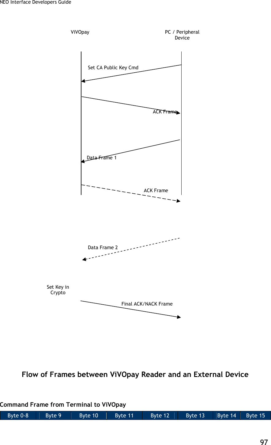
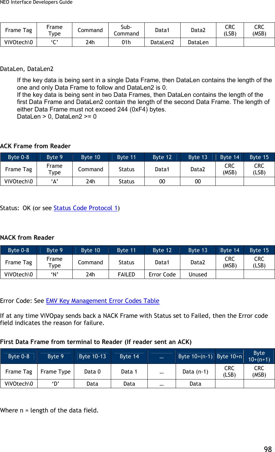
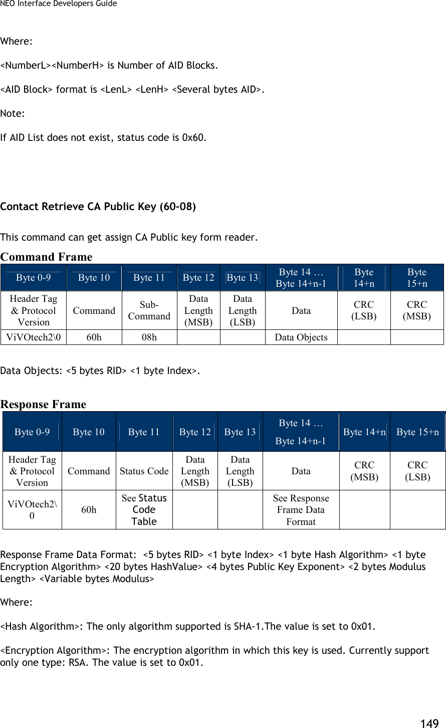
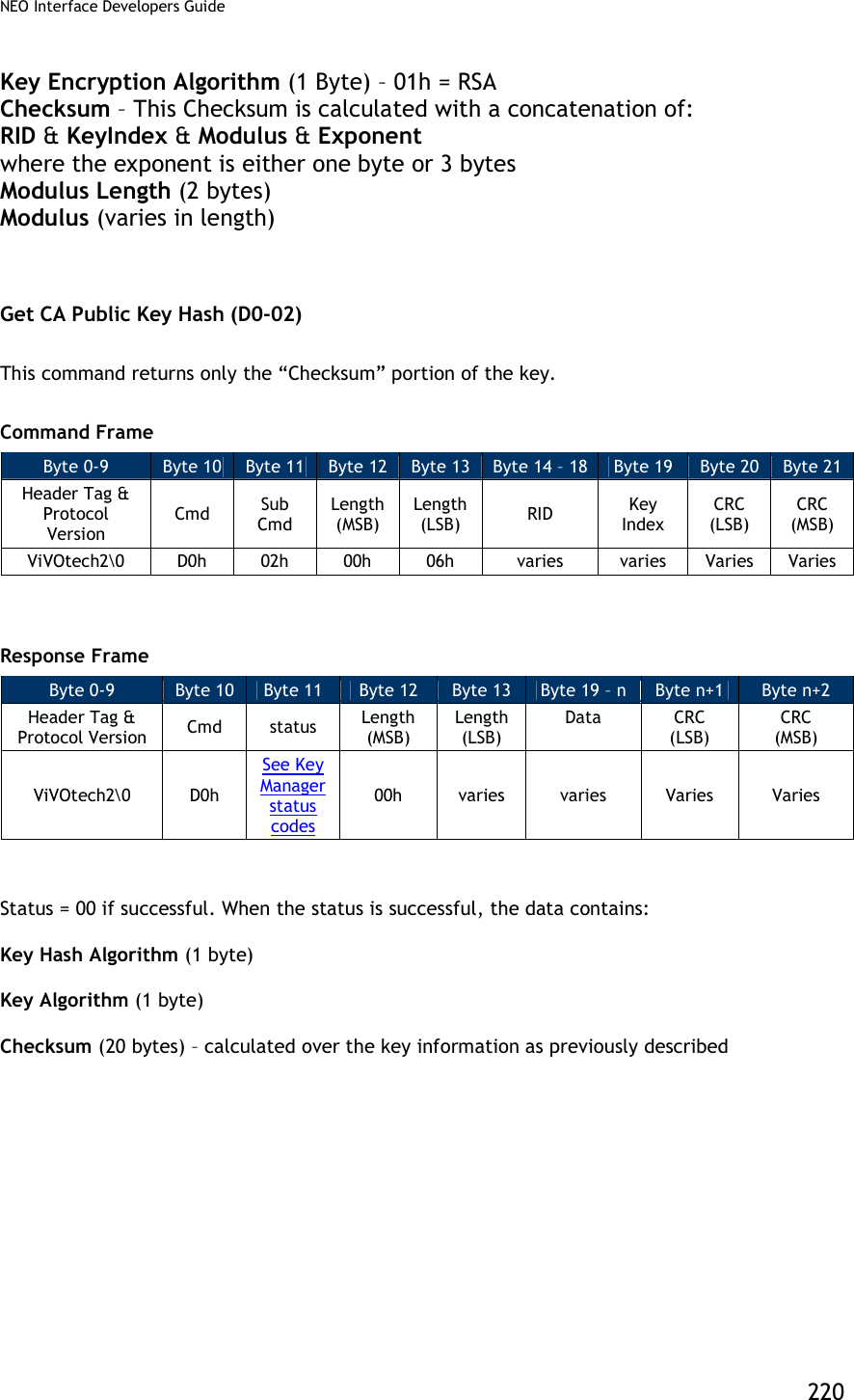
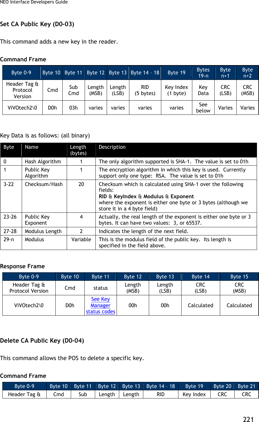
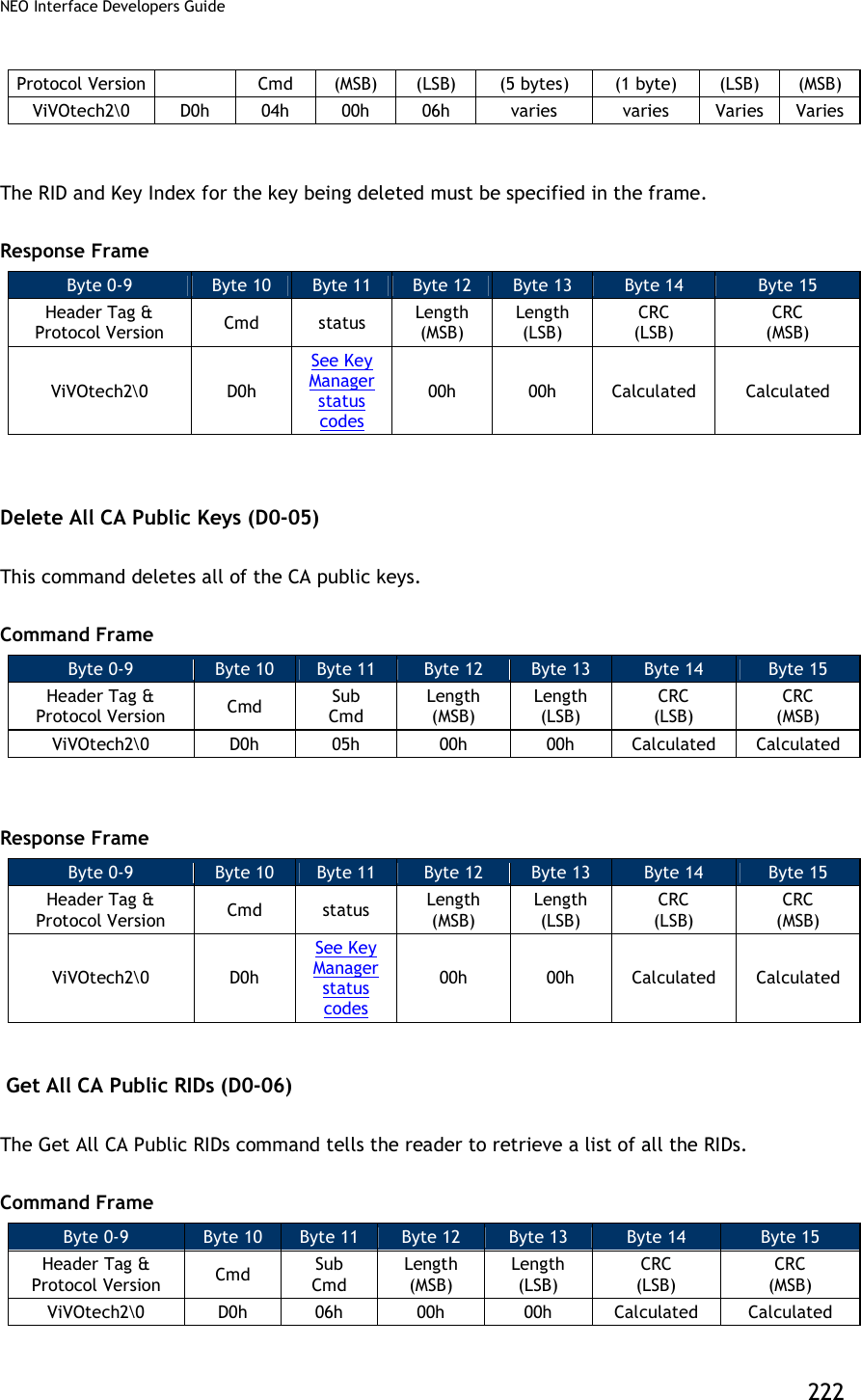
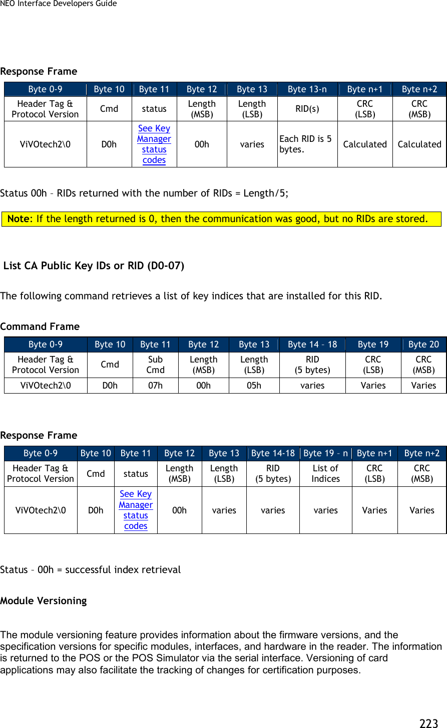
![NEO Interface Developers Guide 99 The data field in the first Data Frame contains the complete or partial CA Public Key related Data. The complete contents and format of the Key Data are given in the following Table. The data portion of Data Frame 1 and Data Frame 2 (if present) when stripped of the Frame overhead and concatenated, provides the data as given in the following table. Table 29: Set CA Public Key Data Field Data Byte Name Length (bytes) Format Notes 0-4 RID 5 Binary Registered Identifier. Necessary for Unique Identification 5 CaPublicKey Index1 1 Binary Index of the CA Public Key for this RID. Necessary for Unique Identification 6 CaHashAlgoIndicator1 1 Binary CA Hash Algorithm to produce Hash-Result in digital signature scheme. Valid Values: 01h: SHA-1 7 CaPublicKeyAlgoIndicator1 1 Binary Digital Signature Algorithm to be used with CA Public Key. Valid Values: 01h: RSA 8-27 CaPublicKeyChecksum1 20 Binary CA Public Key Checksum 28-31 CaPublicKeyExponent1 4 (PICC-based Length may be 1 or 3) Binary CA Public Key Exponent. Value can be 3 (Len=1 Byte) or 216+1=65537=010001h (Len=3 Bytes). We consider it as a 32-bit (4-Byte) Big-Endian number for the Serial Interface and Crypto Storage. The PICC may consider it as a 1-Byte or 3-byte number. 32,33 CaPublicKeyModulusLen 2 Binary CA Public Key (Modulus) Length stored as a Big-Endian number. Aka NCA 34 CaPublicKeyModulus1 Variable (max 256) Binary CA Public Key (Modulus) with Length=NCA [1]: Fields specified by EMV that need to be stored in Terminal Memory (See EMV2000, Book 2, Section 11.2.2 Table 23) ACK Frame from Reader Byte 0-8 Byte 9 Byte 10 Byte 11 Byte 12 Byte 13 Byte 14 Byte 15 Frame Tag Frame Type Command Status Data1 Data2 CRC (MSB) CRC (LSB) ViVOtech\0 ‘A’ 24h Status=OK 00 00 Status: OK (or see Status Code Protocol 1) NACK from Reader Byte 0-8 Byte 9 Byte 10 Byte 11 Byte 12 Byte 13 Byte 14 Byte 15 Frame Tag Frame Type Command Status Data1 Data2 CRC (MSB) CRC (LSB) ViVOtech\0 ‘N’ 24h FAILED Error Code Unused Error Code: See EMV Key Management Error Codes Table](https://usermanual.wiki/ID-TECH/VP3600/User-Guide-3704675-Page-111.png)
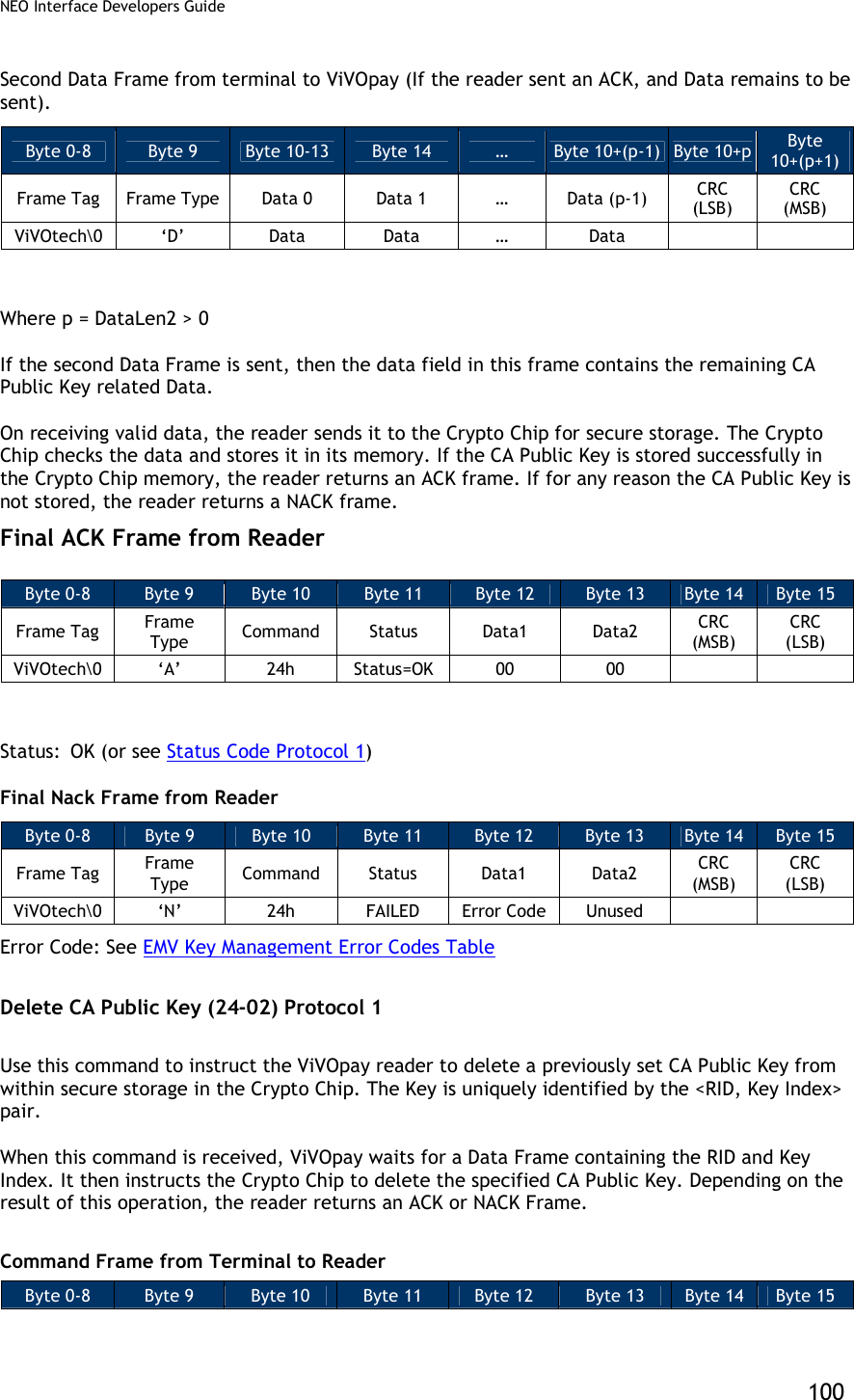
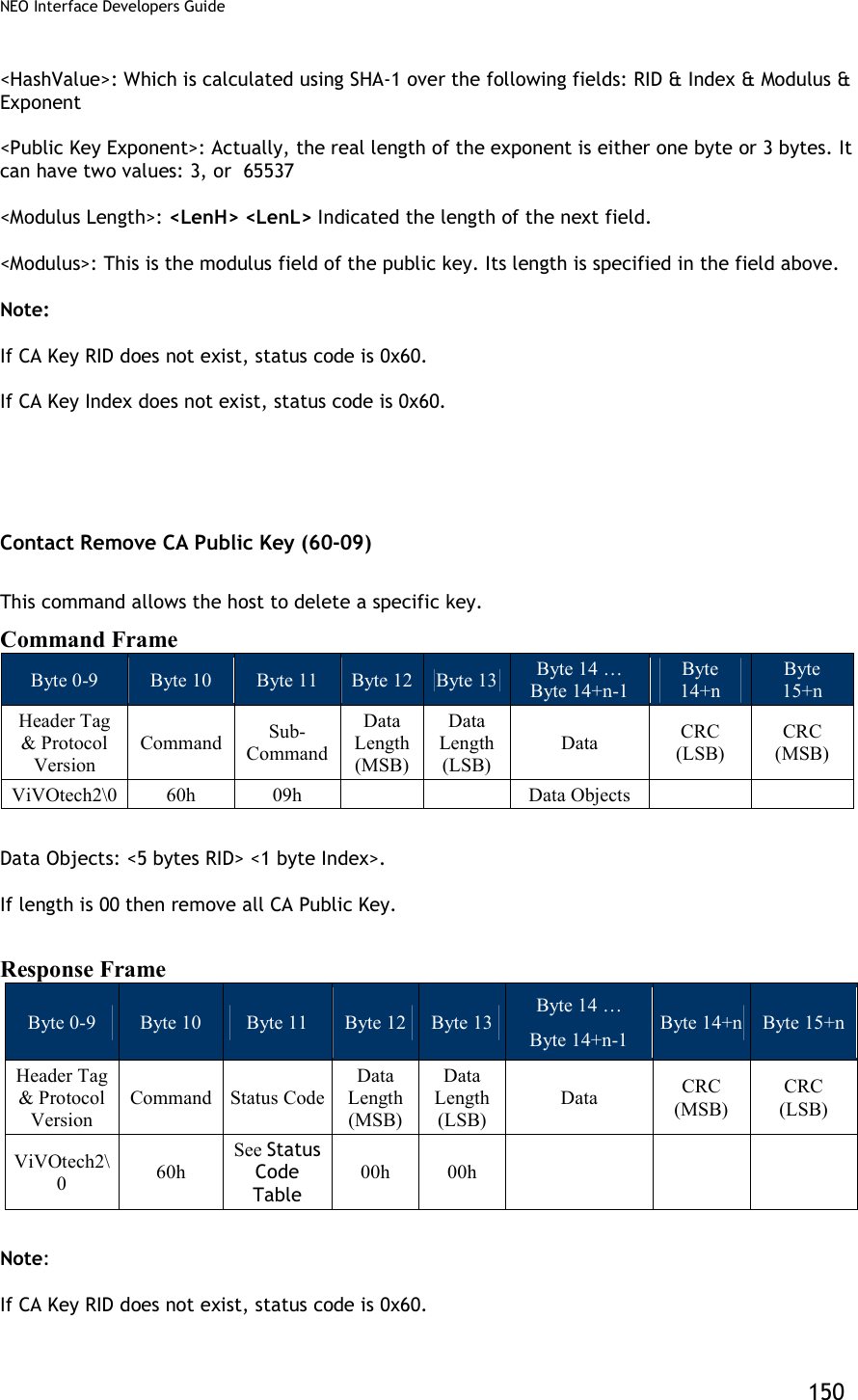
![NEO Interface Developers Guide 101 Frame Tag Frame Type Command Sub-Command Data1 Data2 CRC (LSB) CRC (MSB) ViVOtech\0 ‘C’ 24h 02h 00 DataLen=6 ACK Frame from Reader (or NACK) ACK Frame Byte 0-8 Byte 9 Byte 10 Byte 11 Byte 12 Byte 13 Byte 14 Byte 15 Frame Tag Frame Type Command Status Data1 Data2 CRC (MSB) CRC (LSB) ViVOtech\0 ‘A’ 24h Status=OK 00 00 Status: OK (or see Status Code Protocol 1) NACK Frame Byte 0-8 Byte 9 Byte 10 Byte 11 Byte 12 Byte 13 Byte 14 Byte 15 Frame Tag Frame Type Command Status Data1 Data2 CRC (MSB) CRC (LSB) ViVOtech\0 ‘N’ 24h FAILED Error Code Unused Error Code: See EMV Key Management Error Codes Table Data Frame from Terminal to Reader (If reader sent an ACK) Byte 0-8 Byte 9 Byte 10 … Byte 14 Byte 15 Byte 16 Byte 17 Frame Tag Frame Type Data 0 … Data 4 Data 5 CRC (LSB) CRC (MSB) ViVOtech\0 ‘D’ RID [0] … RID [4] Key Index RID: Registered Identifier (5 Bytes) Key Index: Key Index (1 Byte) The RID, together with the Key Index specifies a unique Key stored in ViVOpay Secure Memory. Final ACK Frame from Reader Byte 0-8 Byte 9 Byte 10 Byte 11 Byte 12 Byte 13 Byte 14 Byte 15 Frame Tag Frame Type Command Status Data1 Data2 CRC (MSB) CRC (LSB) ViVOtech\0 ‘A’ 24h Status=OK 00 00 Status: OK (or see Status Code Protocol 1)](https://usermanual.wiki/ID-TECH/VP3600/User-Guide-3704675-Page-113.png)
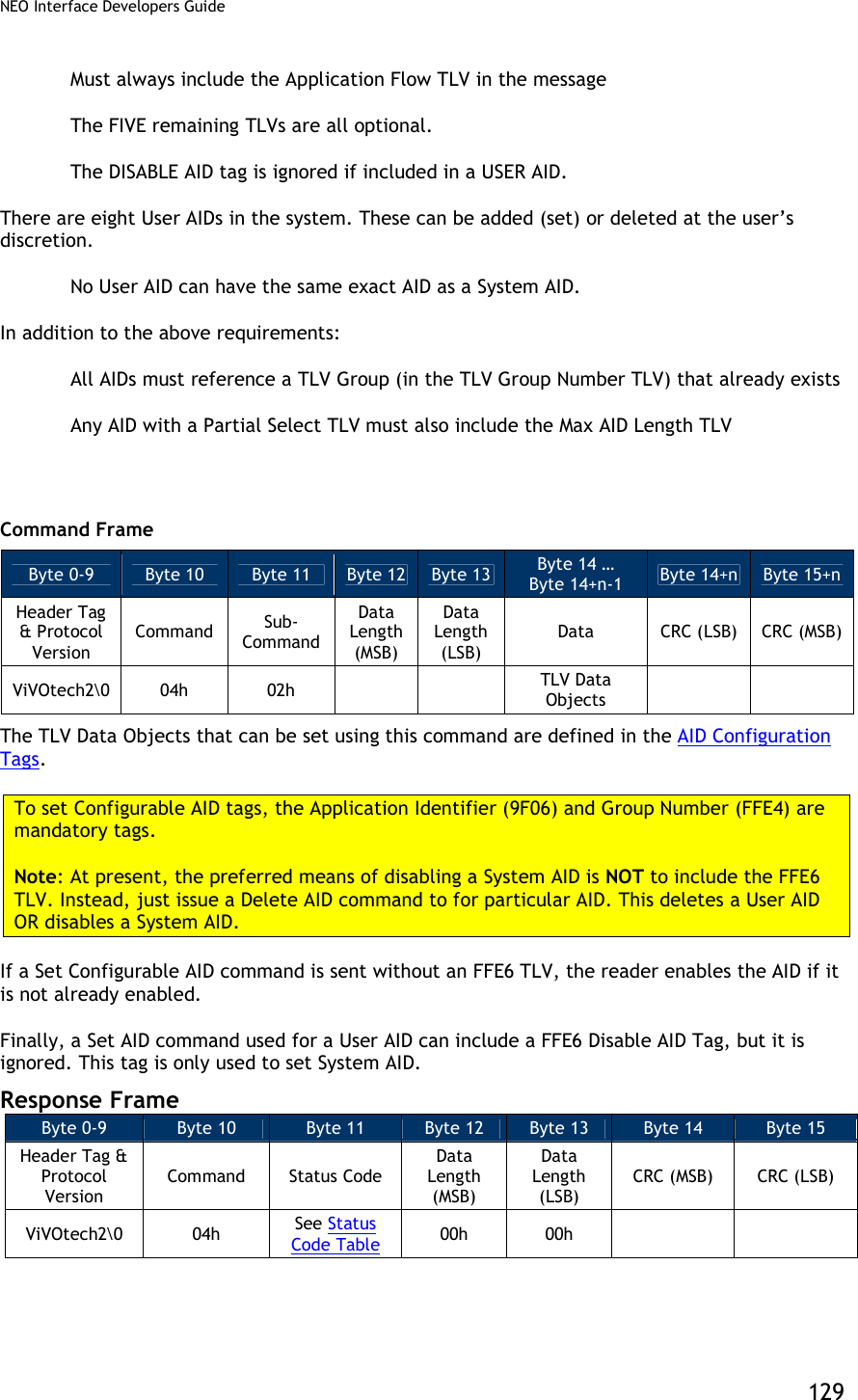
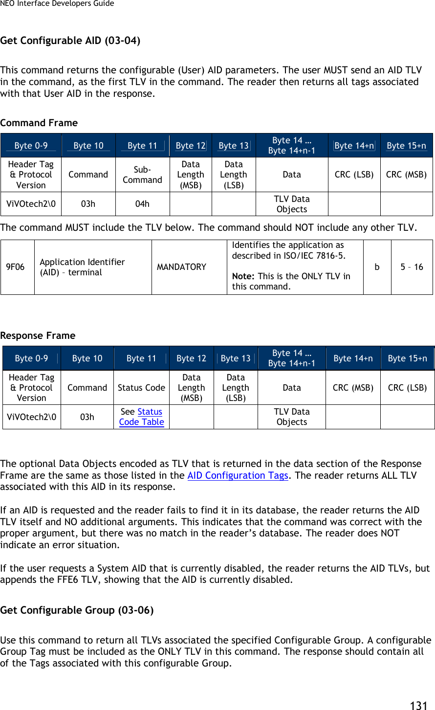
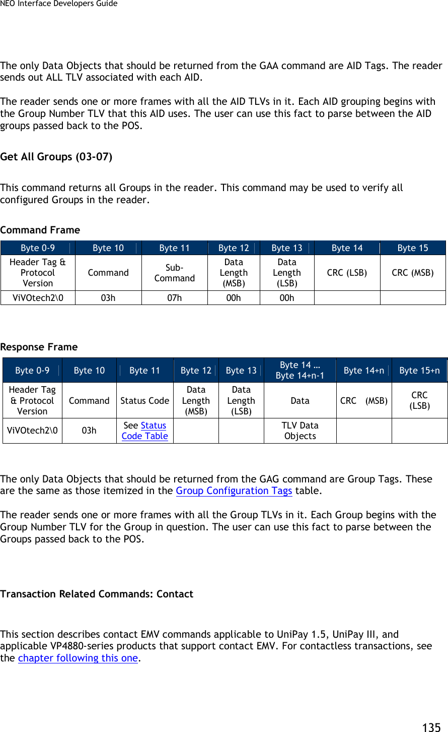
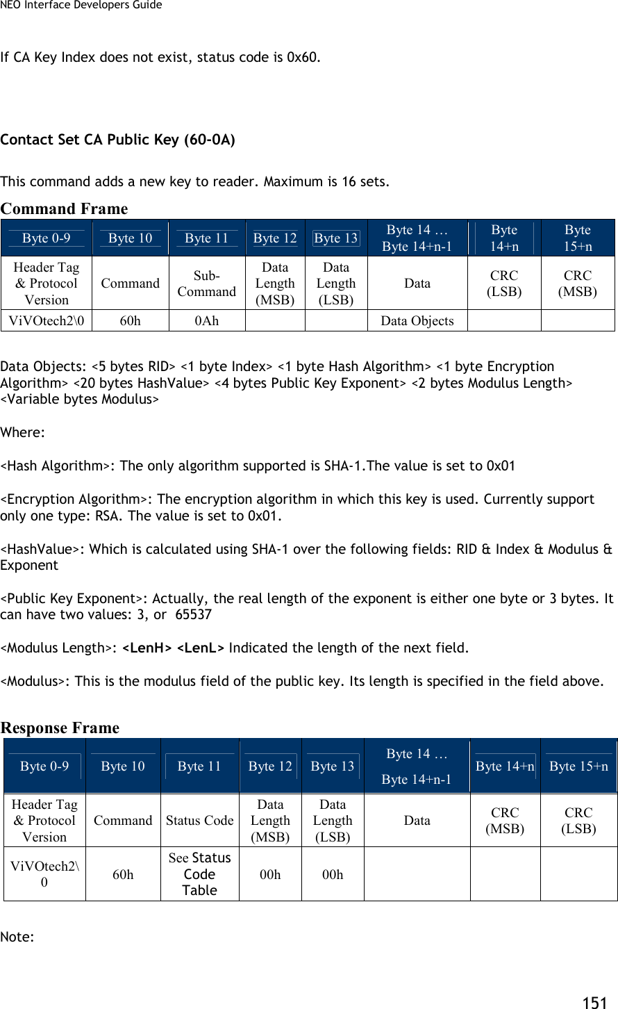
![NEO Interface Developers Guide 132 Command Frame Byte 0-9 Byte 10 Byte 11 Byte 12 Byte 13 Byte 14 … Byte 14+n-1 Byte 14+n Byte 15+n Header Tag & Protocol Version Command Sub-Command Data Length (MSB) Data Length (LSB) Data CRC (LSB) CRC (MSB) ViVOtech2\0 03h 06h TLV Data Objects The following TLV MUST be encoded in the command, it is the ONLY tag included in the command. FFE4[1] Group Number MAND The group that contains the properties for this AID Note: This must be the ONLY TLV in Data Field. n2 1 [1] These objects use proprietary tags. The use of these tags should be restricted to the serial interface. Once the reader has received these values and saved them in memory, it should dispose of the tags (and not keep them associated with these two values). Response Frame Byte 0-9 Byte 10 Byte 11 Byte 12 Byte 13 Byte 14 … Byte 14+n-1 Byte 14+n Byte 15+n Header Tag & Protocol Version Command Status Code Data Length (MSB) Data Length (LSB) Data CRC (MSB) CRC (LSB) ViVOtech2\0 03h See Status Code Table TLV Data Objects The Data Objects encoded as TLV that is returned in the data section of the Response Frame are given in the Group TLV Objects Table. If the user requests a Group that is illegal, an error response is sent back. If the user requests a valid Group number but the Group does NOT exist, then the reader returns the regular response but only includes the Group Number TLV (no other TLV is included). This signifies that the user has requested a valid number but no Group has been assigned to it. Note: For a PayPass group, if a TLV data item is not present in the Group then it will not be present in the data returned by this command. However, this does not mean that there is no value for this particular TLV in order to perform a transaction. It is possible that the PayPass Kernel may have a hard-coded value for this TLV which will be used in a transaction if the TLV is not present in the Group or in Activate Transaction data. The data items for which the PayPass kernel has hard-coded default values are given in in the section on PayPass Group Configuration TLVs with Hard-Coded Values in Kernel. Delete Configurable AID (04-04) This command deletes a configurable AID. It is MANDATORY to include the AID TLV of the AID to be removed. No other TLVs should be included.](https://usermanual.wiki/ID-TECH/VP3600/User-Guide-3704675-Page-144.png)
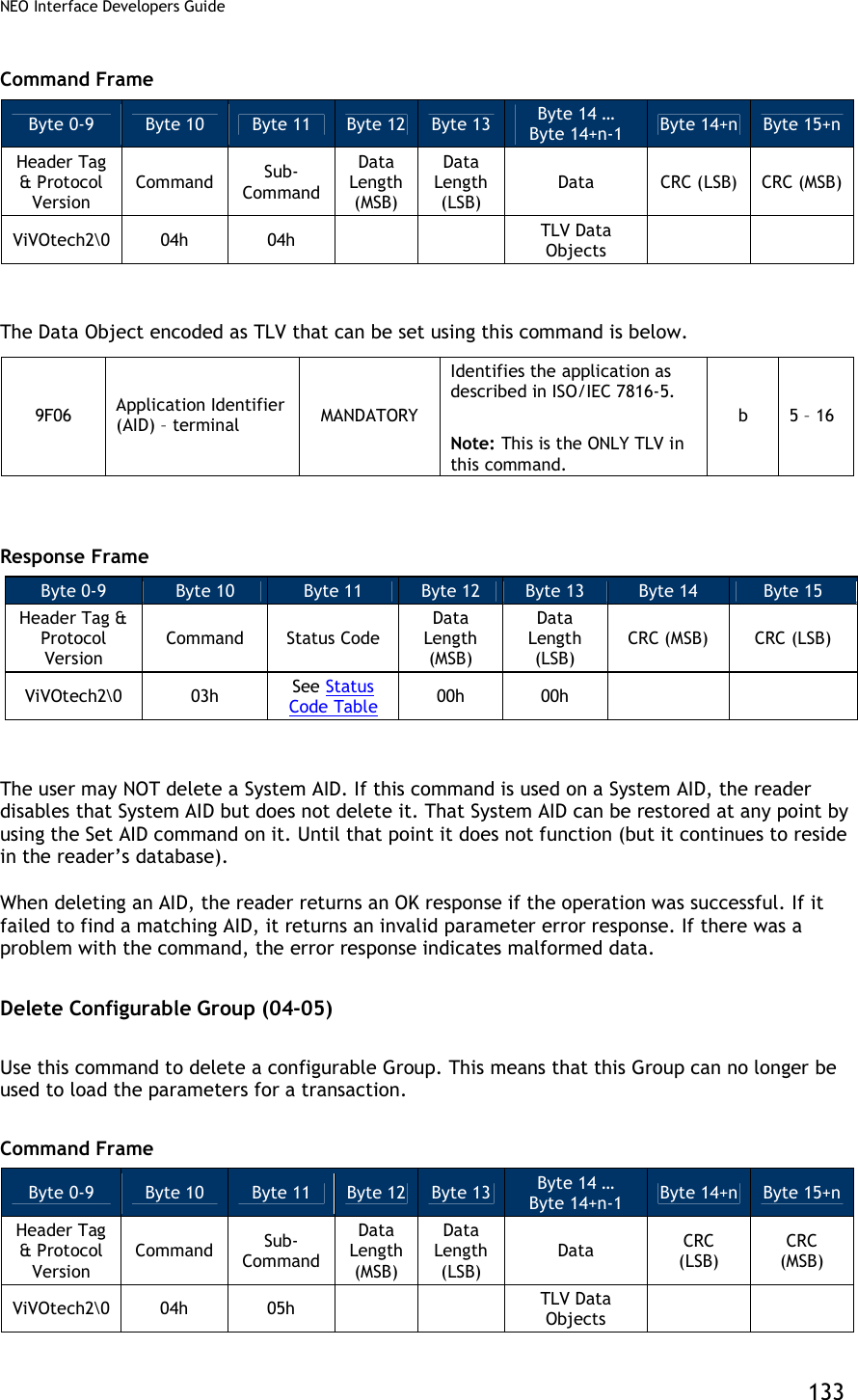
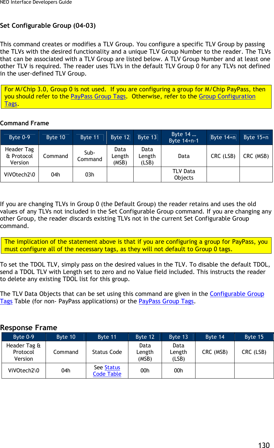
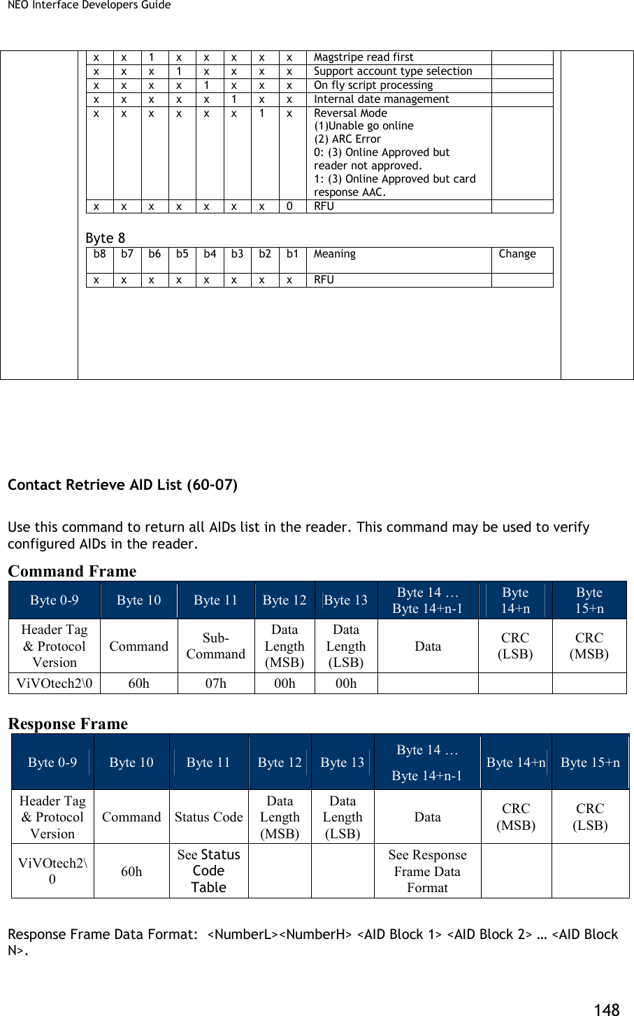
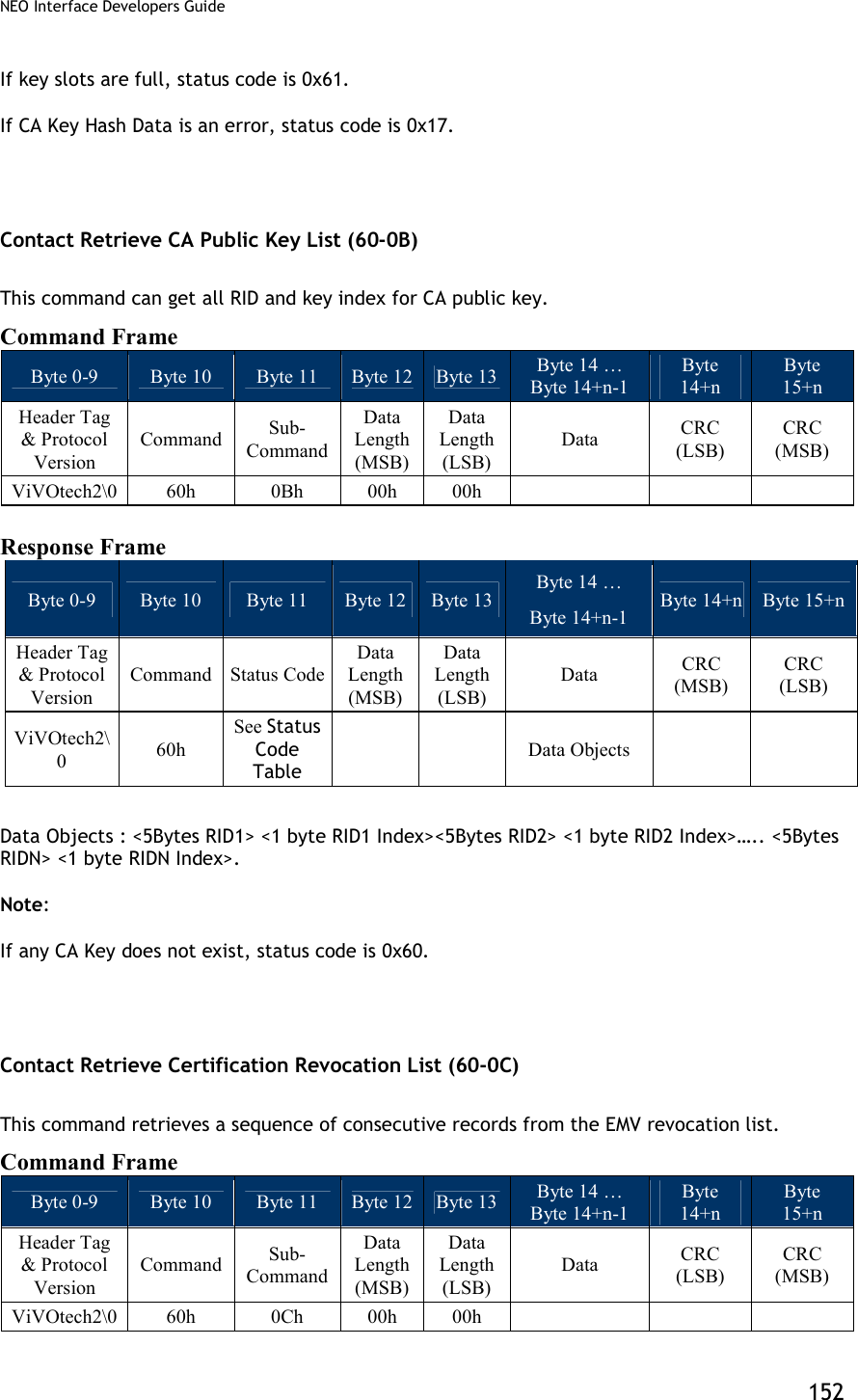
![NEO Interface Developers Guide 134 It is MANDATORY to include the Group Number TLV of the Group the user wishes to delete. No other TLVs should be included. FFE4[1] Group Number MAND The group that contains the properties for AID Note: This must be the ONLY TLV in Data Field. n2 1 [1] These objects use proprietary tags. The use of these tags should be restricted to the serial interface. Once the reader has received these values and saved them in memory, the Terminal should dispose of the tags. Response Frame Byte 0-9 Byte 10 Byte 11 Byte 12 Byte 13 Byte 14 Byte 15 Header Tag & Protocol Version Command Status Code Data Length (MSB) Data Length (LSB) CRC (MSB) CRC (LSB) ViVOtech2\0 04h See Status Code Table 00h 00h Do NOT delete the Default Group 0. The reader does not allow this command, and does NOT disable Group 0; instead it returns an error. If the Group is not a valid Group Number this returns an error. Finally, if the reader has ANY AID that references this Group, it does NOT delete the Group. It returns an error. That is, ONLY Groups that are NOT referenced by existing AID can be deleted. In this situation, the user must first delete or modify these AIDs, and then delete the Group. Get All AIDs (03-05) Use this command to return all AIDs in the reader. This command may be used to verify configured AIDs or to determine what System AIDs are in the reader. Command Frame Byte 0-9 Byte 10 Byte 11 Byte 12 Byte 13 Byte 14 Byte 15 Header Tag & Protocol Version Command Sub-Command Data Length (MSB) Data Length (LSB) CRC (LSB) CRC (MSB) ViVOtech2\0 03h 05h 00h 00h Response Frame Byte 0-9 Byte 10 Byte 11 Byte 12 Byte 13 Byte 14 … Byte 14+n-1 Byte 14+n Byte 15+n Header Tag & Protocol Version Command Status Code Data Length (MSB) Data Length (LSB) Data CRC (MSB) CRC (LSB) ViVOtech2\0 03h See Status Code Table TLV Data Objects](https://usermanual.wiki/ID-TECH/VP3600/User-Guide-3704675-Page-146.png)
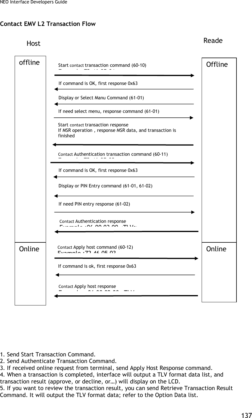
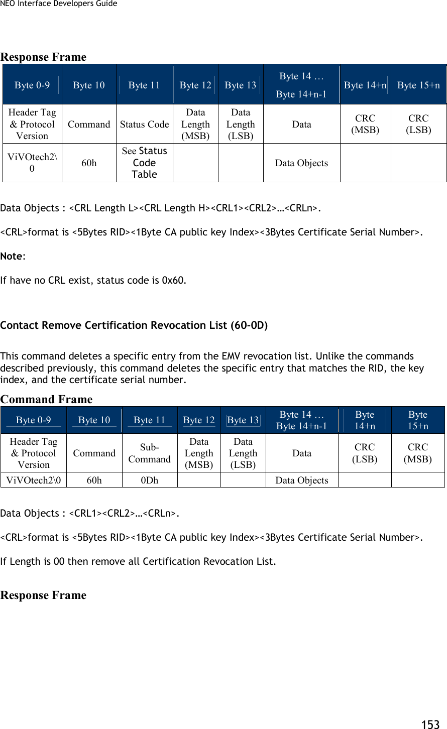
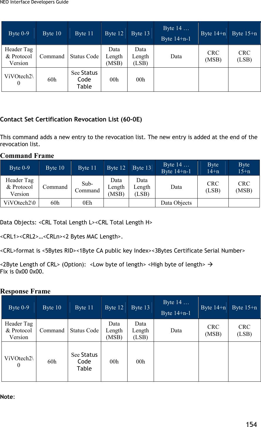
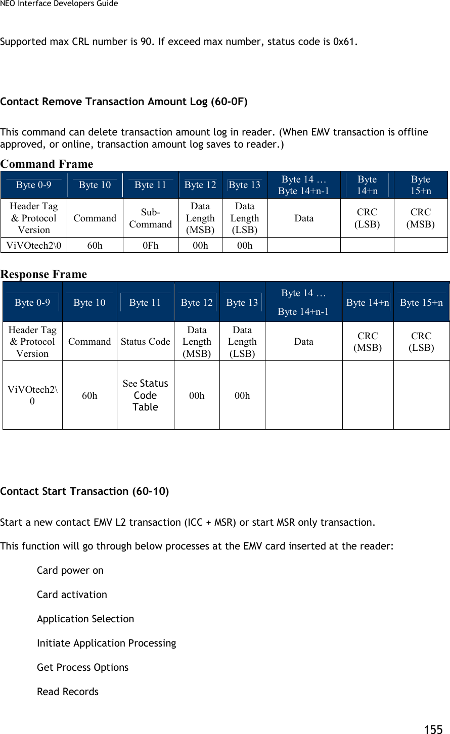
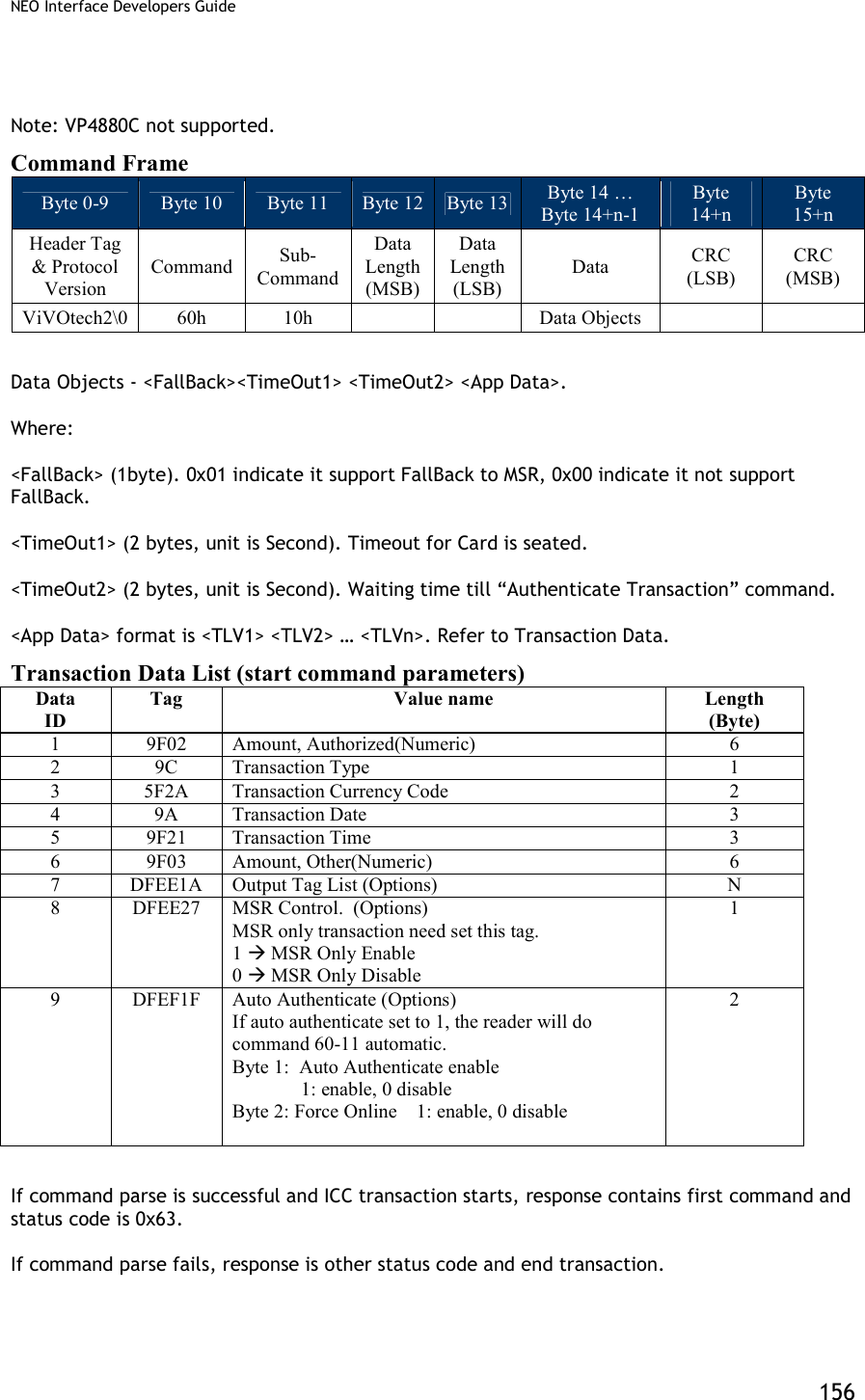
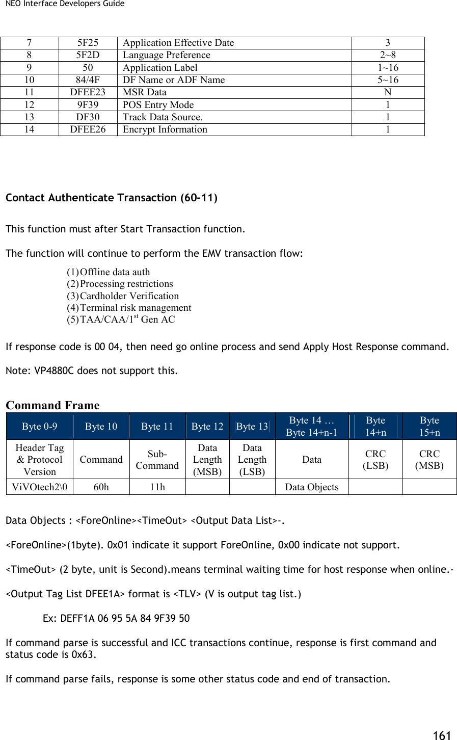
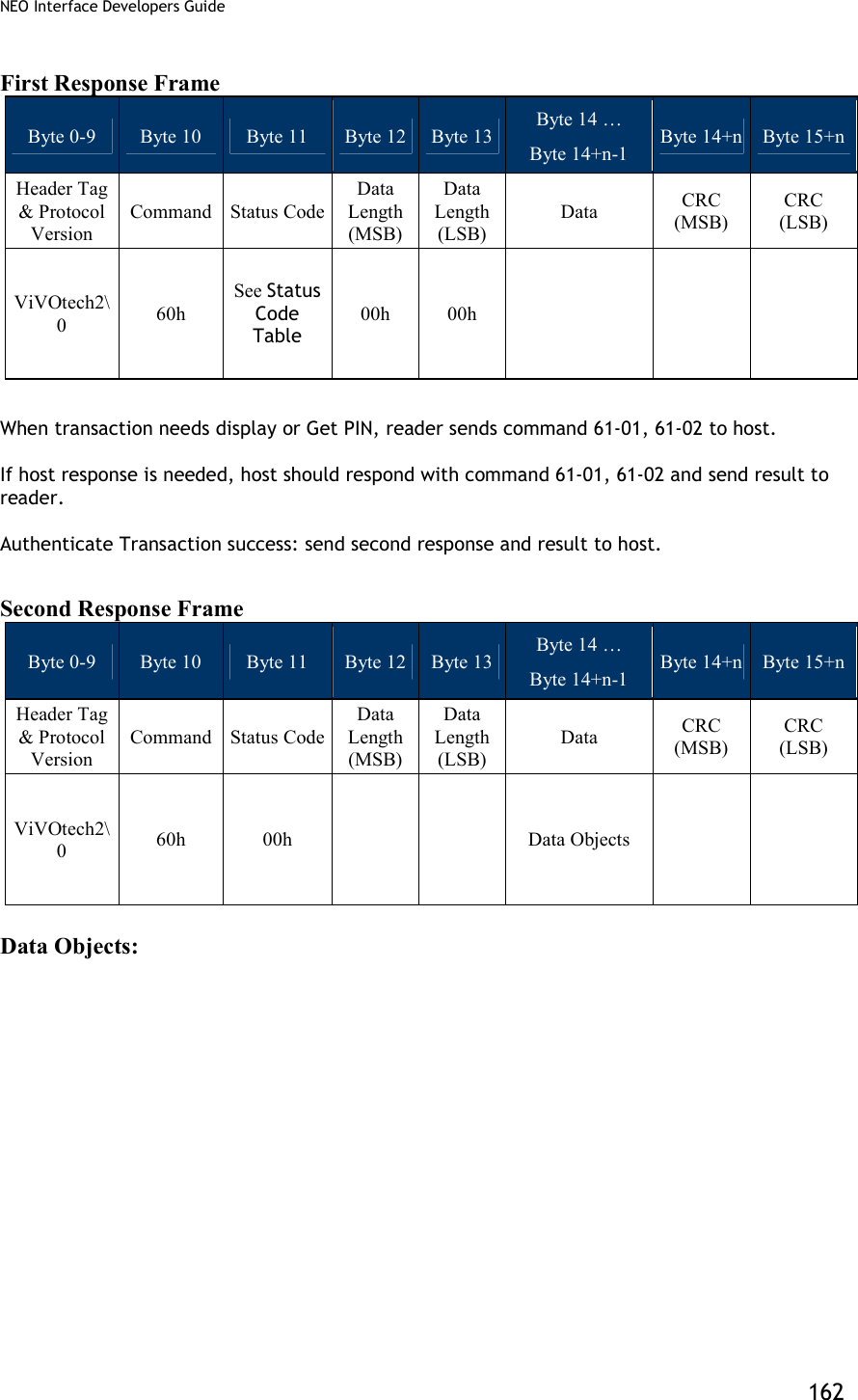
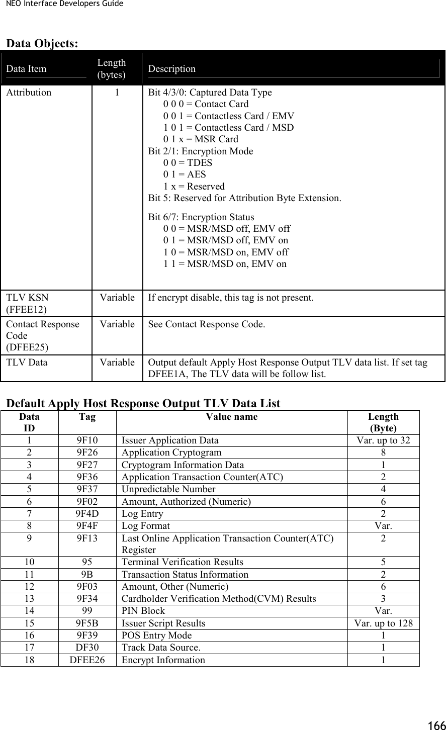
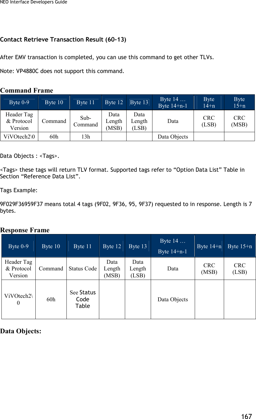
![NEO Interface Developers Guide 164 Contact Apply Host Response (60-12) This function is the last step in EMV transaction flow. The function will send acquirer data (if online) to the card and notify that the transaction is complete. This function will do the following process upon the transaction type (may or may not perform each step, depending upon acquirer’s requirement and response): (1) External Authenticate (2) Script Processing (3) 2nd Gen AC (4) Completion Note: VP4880C does not support this command. Command Frame Byte 0-9 Byte 10 Byte 11 Byte 12 Byte 13 Byte 14 … Byte 14+n-1 Byte 14+n Byte 15+n Header Tag & Protocol Version Command Sub-Command Data Length (MSB) Data Length (LSB) Data CRC (LSB) CRC (MSB) ViVOtech2\0 60h 12h Data Objects Data Objects : <1Byte ComFlag> [<Authorization Response Code (TLV,Tag 8A)>< Issuer Authentication Data (TLV, Tag 91)>< <Scripts (TLV, Tag 71/72)>] <Output Data List> Where: <1Byte ComFlag>:0x01 indicate online with host,0x00 indicate unable online. Data in [ ] indicate these data is optional: If ComFlag is 0x01, the Data exist. If ComFlag is 0x00, the Data does not exist. <Output Tag List DFEE1A> format is <TLV> (V is output tag list.) Ex: DEFF1A 06 95 5A 84 9F39 50 If command parse is success and ICC transactions continue, response first command and status code is 0x63. If command parse is failed, response other status code and end transaction.](https://usermanual.wiki/ID-TECH/VP3600/User-Guide-3704675-Page-176.png)
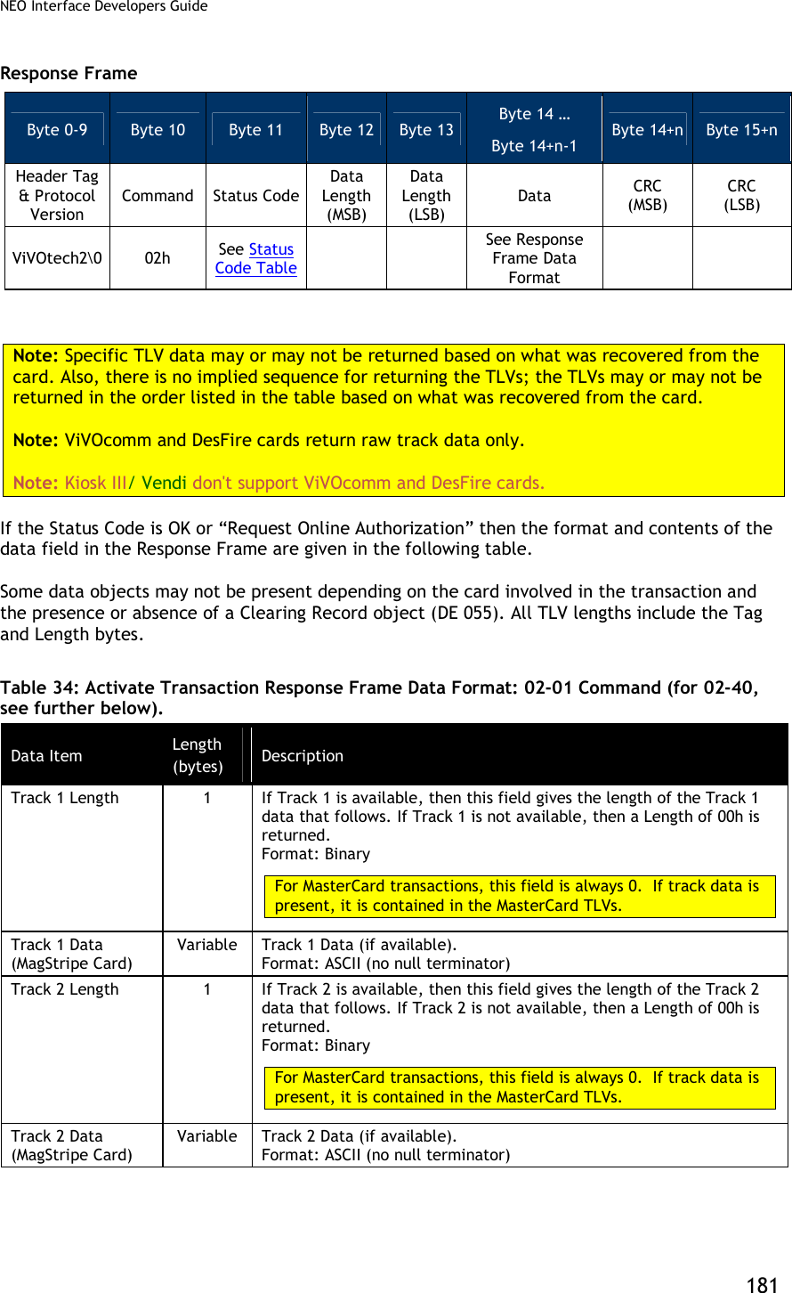
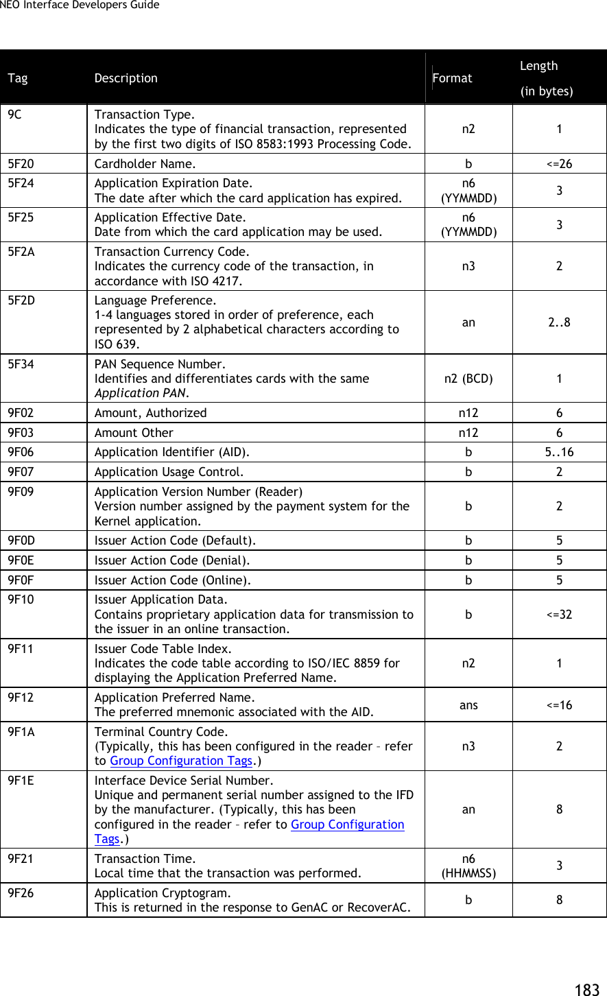
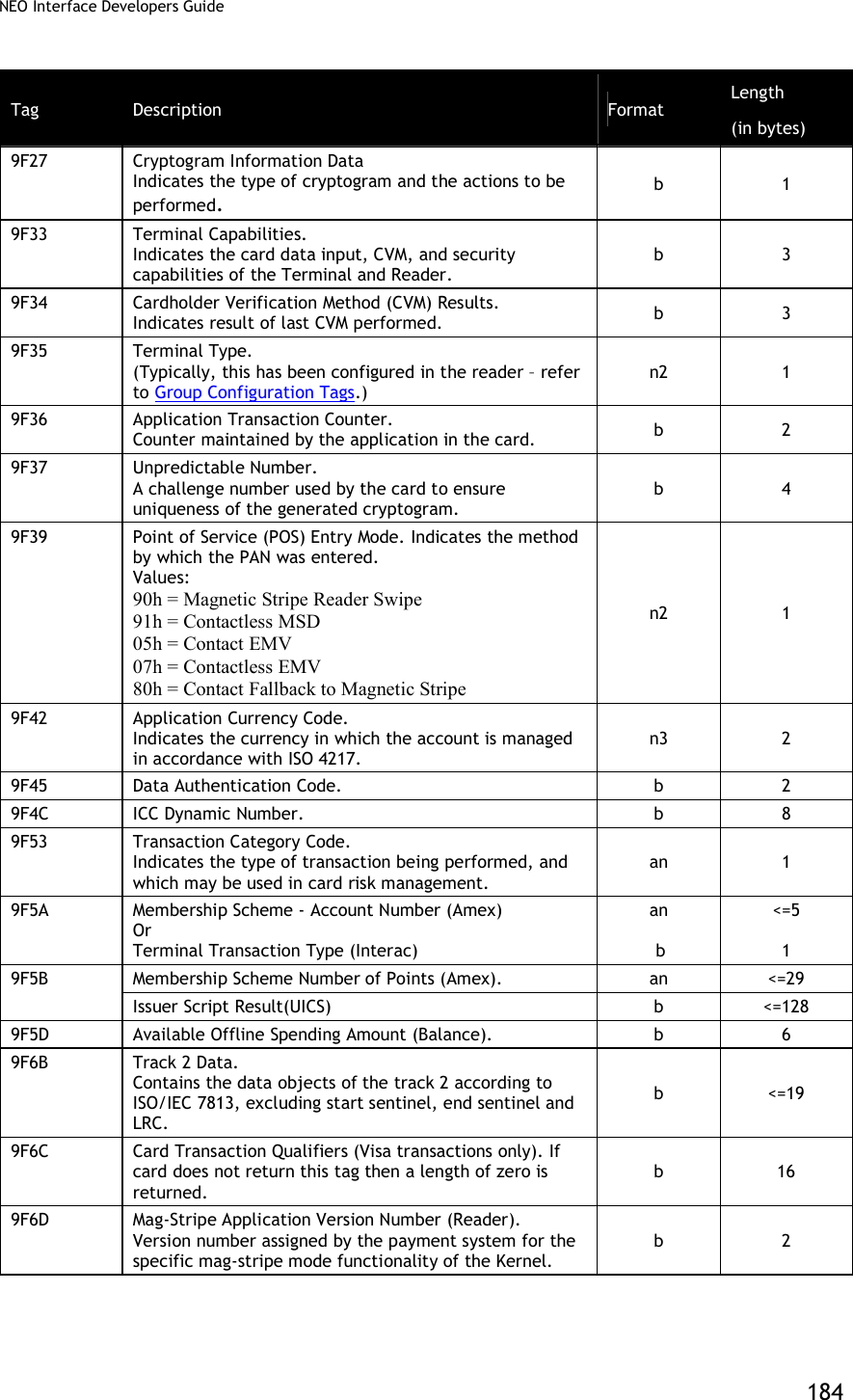
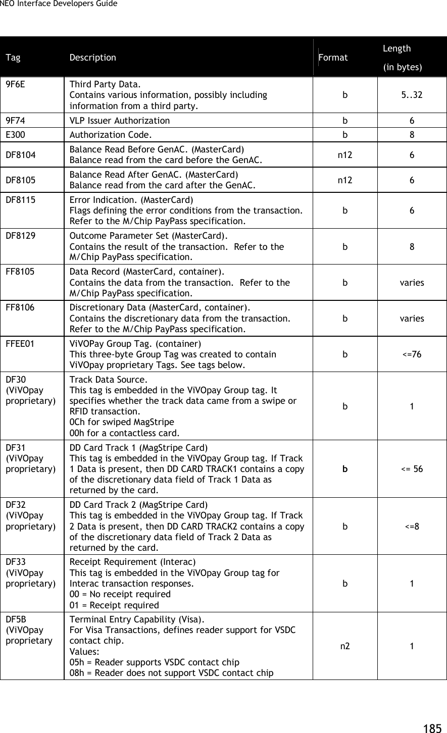
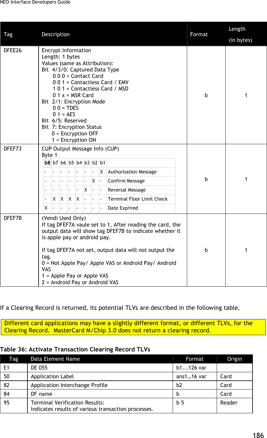
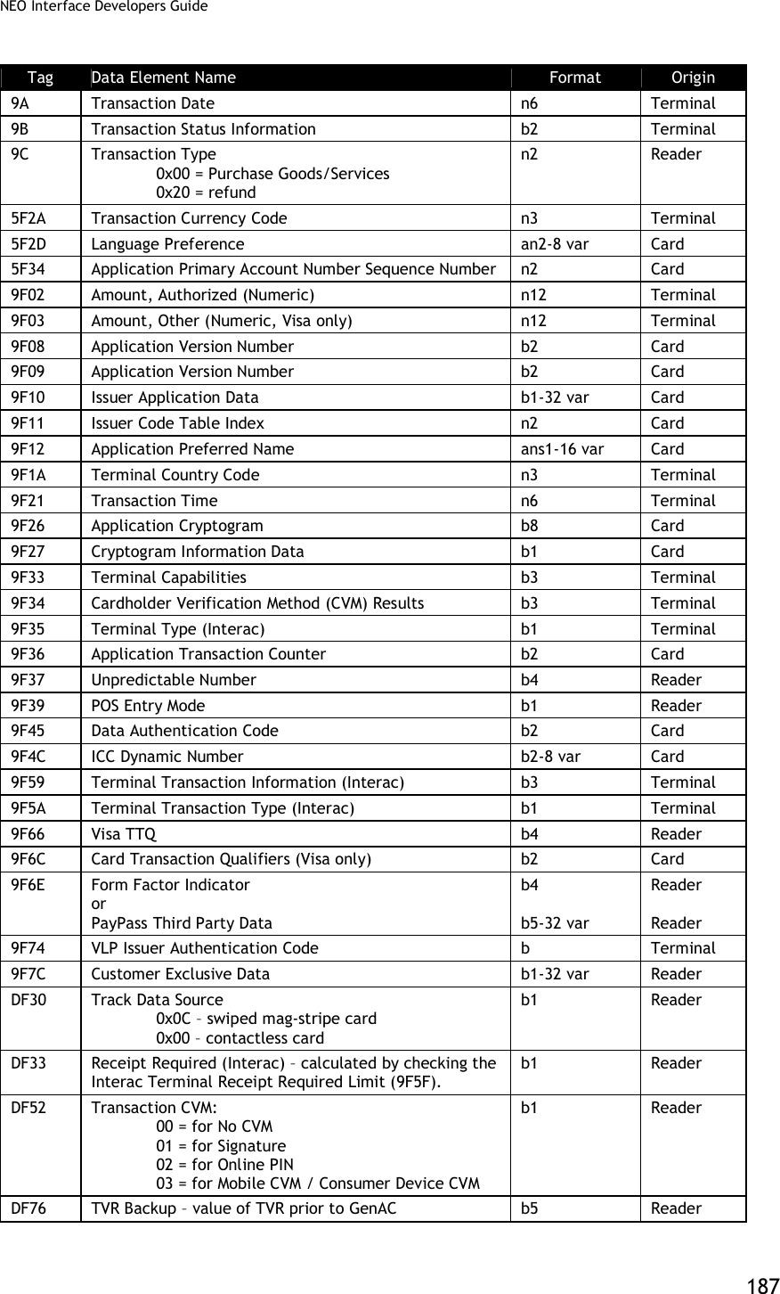
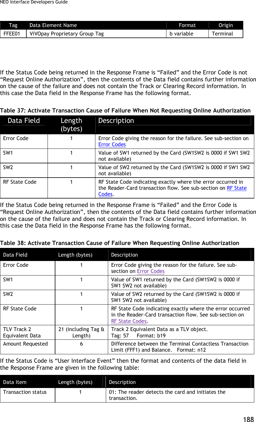
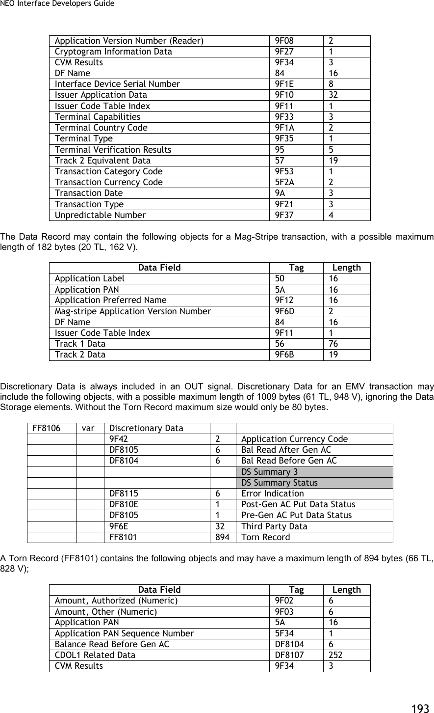
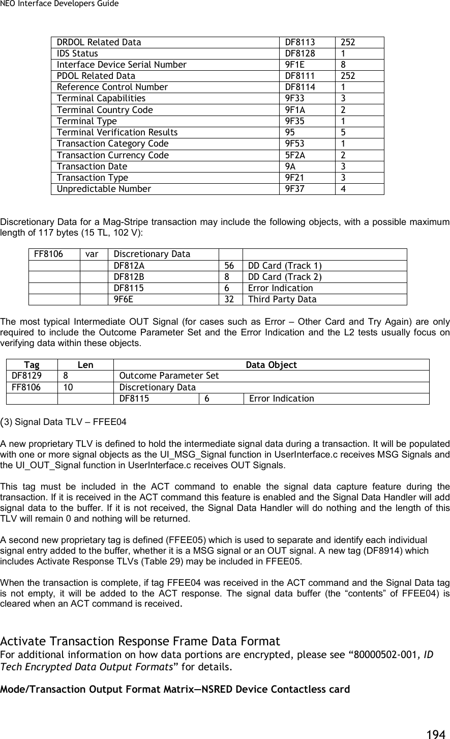
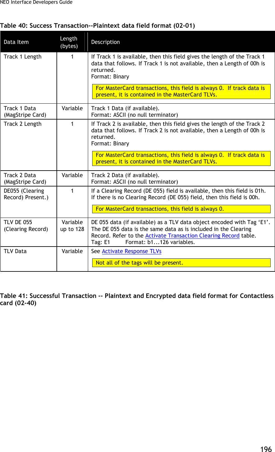
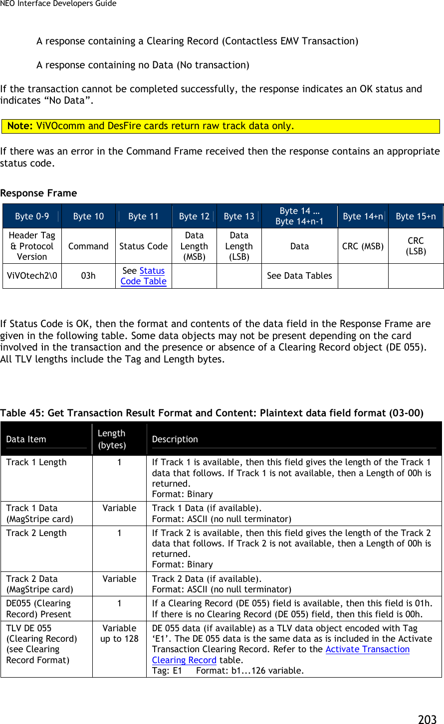
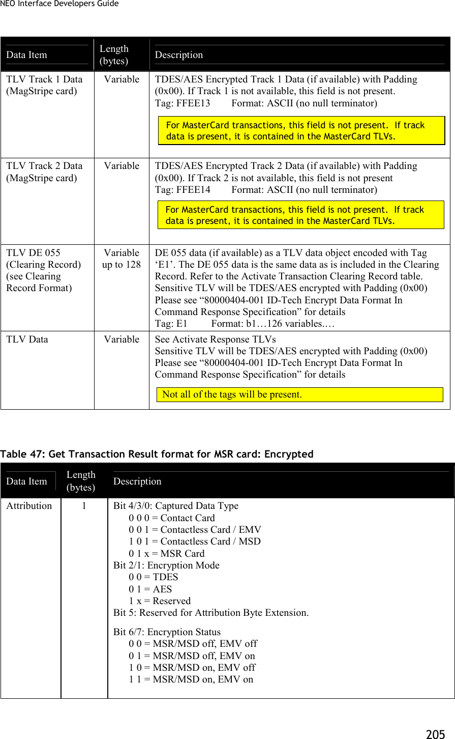
![NEO Interface Developers Guide 182 Data Item Length (bytes) Description DE055 (Clearing Record) Present.) 1 If a Clearing Record (DE 055) field is available, then this field is 01h. If there is no Clearing Record (DE 055) field, then this field is 00h. For MasterCard transactions, this field is always 0. TLV DE 055 (Clearing Record) Variable up to 128 DE 055 data (if available) as a TLV data object encoded with Tag ‘E1’. The DE 055 data is the same data as is included in the Clearing Record. Refer to the Activate Transaction Clearing Record table. Tag: E1 Format: b1...126 variables. TLV Data Variable See Activate Response TLVs below. Not all of the tags will be present. MasterCard transactions do not return a Clearing Record or the track data fields. Tags are returned in a format specified by M/Chip 3.0. Track 1 and Track2 data are encapsulated in tags according to the MasterCard specification. Table 35: Activate Transaction Response TLVs Tag Description Format Length (in bytes) 50 Application Label. Name associated with the AID, in accordance with ISO/IEC 7816-5. an <= 16 56 Track 1 Equivalent Data. Contains the data objects of the track 1 according to [ISO/IEC 7813] Structure B, excluding start sentinel, end sentinel and LRC. The Track 1 Data may be present in the file read using the READ RECORD command during a mag-stripe mode transaction. ans <=79 57 Track 2 Equivalent Data. Contains the data objects of the track 2, in accordance with ISO/IEC 7813, excluding start sentinel, end sentinel, and LRC. b <=19 5A Application Primary Account Number (PAN). The cardholder account number. cn <=19 (10 bytes) 82 Application Interchange Profile. Indicates the capabilities of the Card to support specific functions in the application. b 2 84 DF Name. Identifies the name of the DF as described in ISO/IEC 7816-4. b 5..16 95 Terminal Verification Results. Status of various functions from the terminal perspective. b 5 99 Online PIN Block n 16 9A Transaction Date. Local date that the transaction was performed. n6 (YYMMDD) 3 9B Transaction Status Information. b 2](https://usermanual.wiki/ID-TECH/VP3600/User-Guide-3704675-Page-194.png)
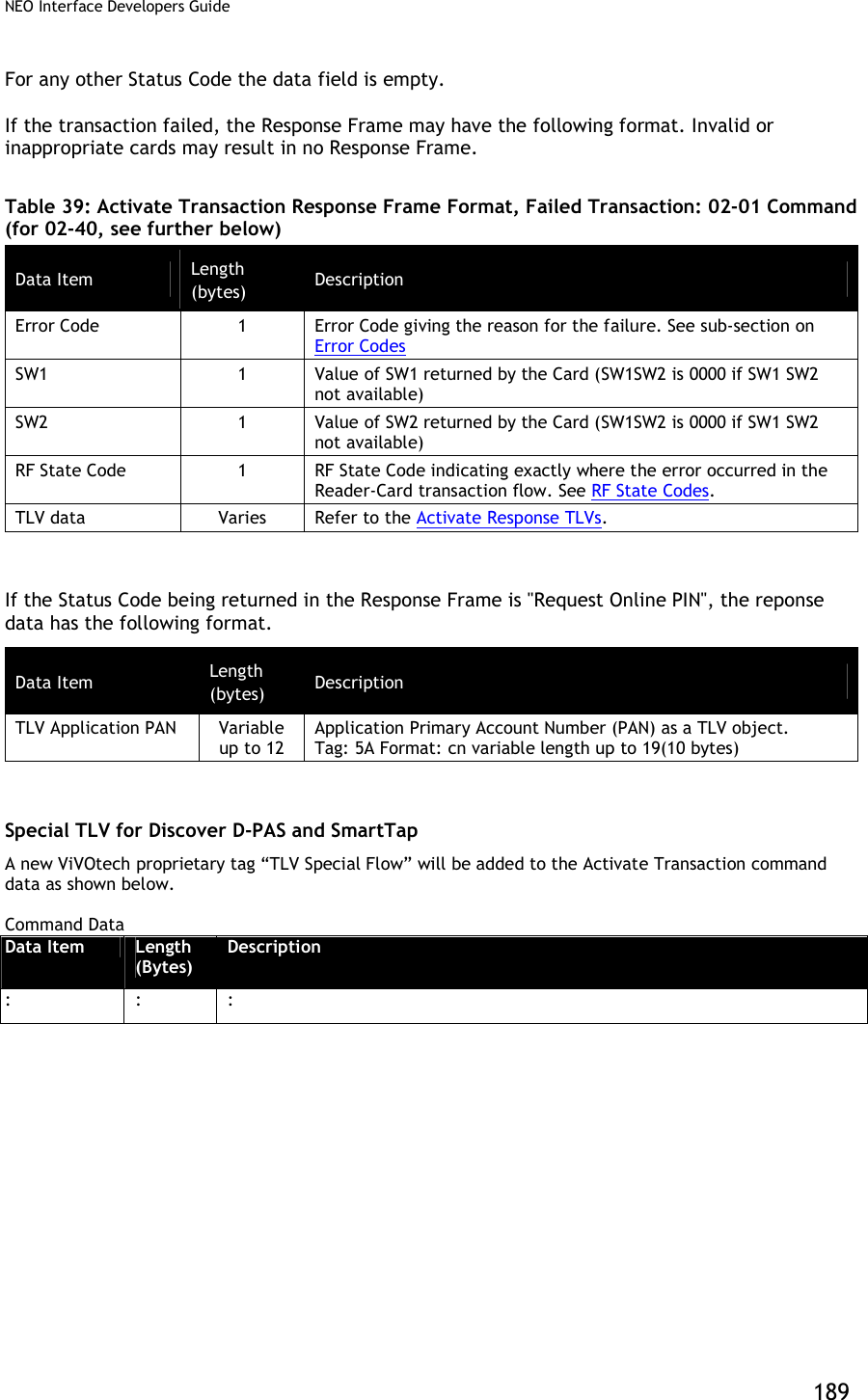
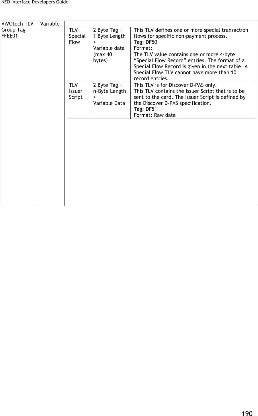
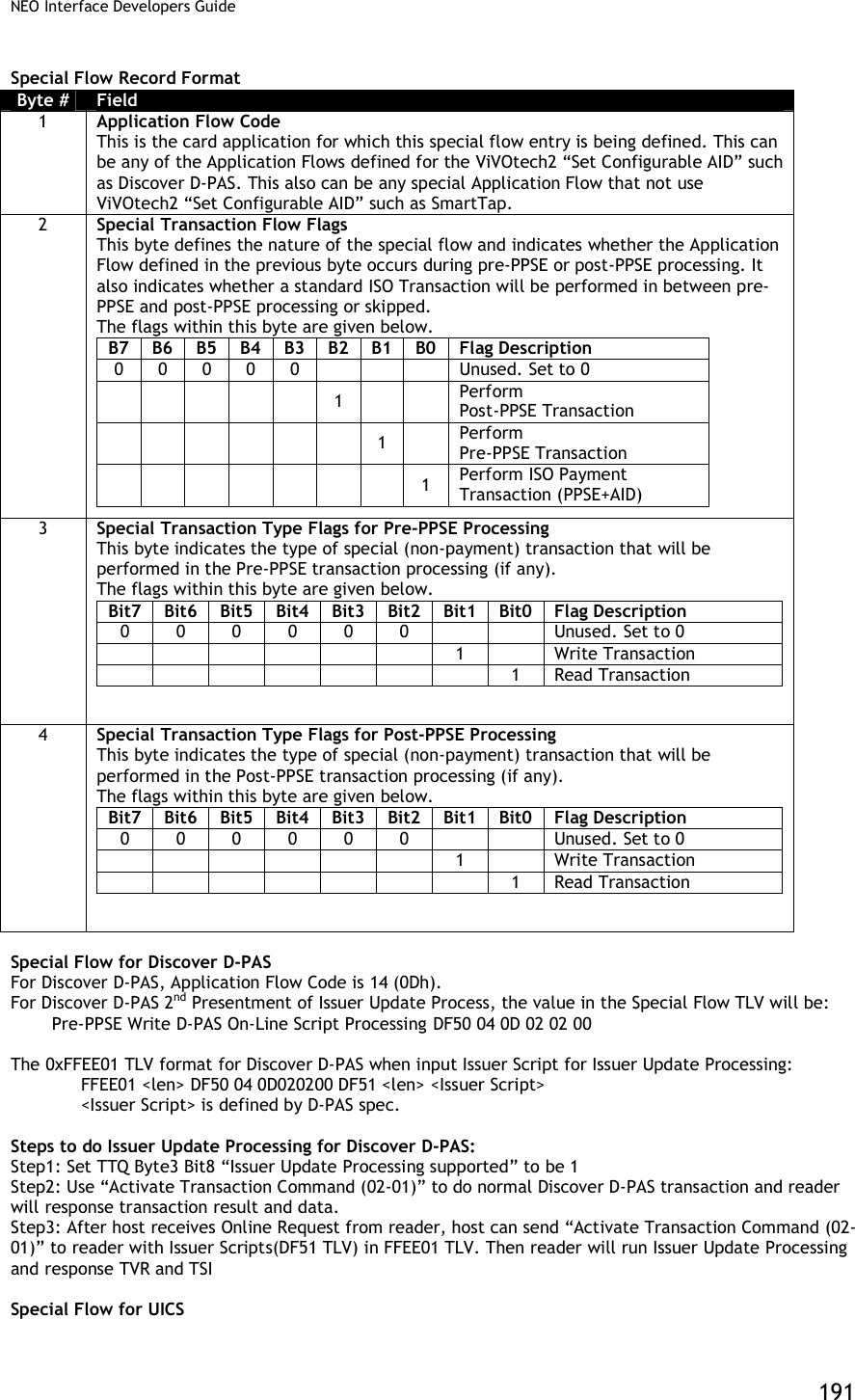
![NEO Interface Developers Guide 192 For UICS, the special flow code ,Issuer Script format and usage is the same as D-PAS. Special TLV for PayPass Application This design connects the M/Chip signal handling to the existing GR user interface module (“Process D”) to support MSG and OUT signals in ViVOpay readers with displays. Reference files [1] EMV Contactless Book C-2, Kernel 2 Specification, v2.3 [2] PayPass Test Cases for PayPass v3.0 Level 2 Reader Testing, Aug 2011 [3] EMV Contactless Specifications for Payment Systems, Book A, Architecture and General Requirements, v2.3 [4] PayPass M/Chip Reader Card Application Interface Specification v3.0.2 [5] Engineering Specification, MChip 3.0 on GR, v1.6 (1) MSG Signals MSG Signals are used by other processes to send the User Interface Request Data to Process D. Process D manages the User Interface Requests as defined in reference [3] and displays a message and/or a status. The User Interface Request Data is defined in reference [1] as tag DF8116 and holds twenty-two bytes of data as shown in the table below: Data Field Length Message Identifier 1 Status 1 Hold Time 3 Language Preference 8 Value Qualifier 1 Value 6 Currency Code 2 (2) OUT Signals OUT Signals are used by the kernel (Process K) to indicate the outcome of a transaction. According to reference [1] the OUT signal may comprise the following objects. Data Field Tag Length Outcome Parameter Set DF8129 8 Data Record (if any) FF8105 var. Discretionary Data FF8106 var. User Interface Request Data (if any) DF8116 22 According to reference [1], all objects listed below are to be added to the output buffer if they are present. The Data Record (FF8105) may contain the following objects for an EMV transaction, with a maximum length of 256 bytes (74 TL, 182 V). Data Field Tag Length Amount, Authorized (Numeric) 9F02 6 Amount, Other (Numeric) 9F03 6 Application Cryptogram 9F26 8 Application Expiration Date 5F24 3 Application Interchange Profile 82 2 Application Label 50 16 Application PAN 5A 16 Application PAN Sequence Number 5F34 1 Application Preferred Name 9F12 16 Application Transaction Counter 9F36 2](https://usermanual.wiki/ID-TECH/VP3600/User-Guide-3704675-Page-204.png)
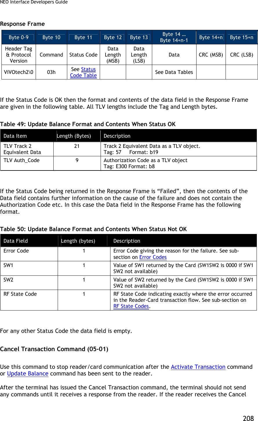
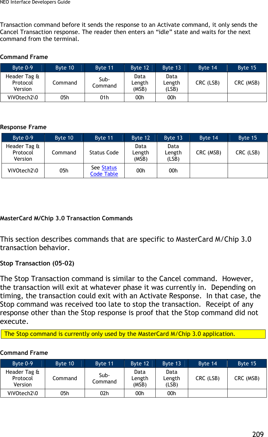
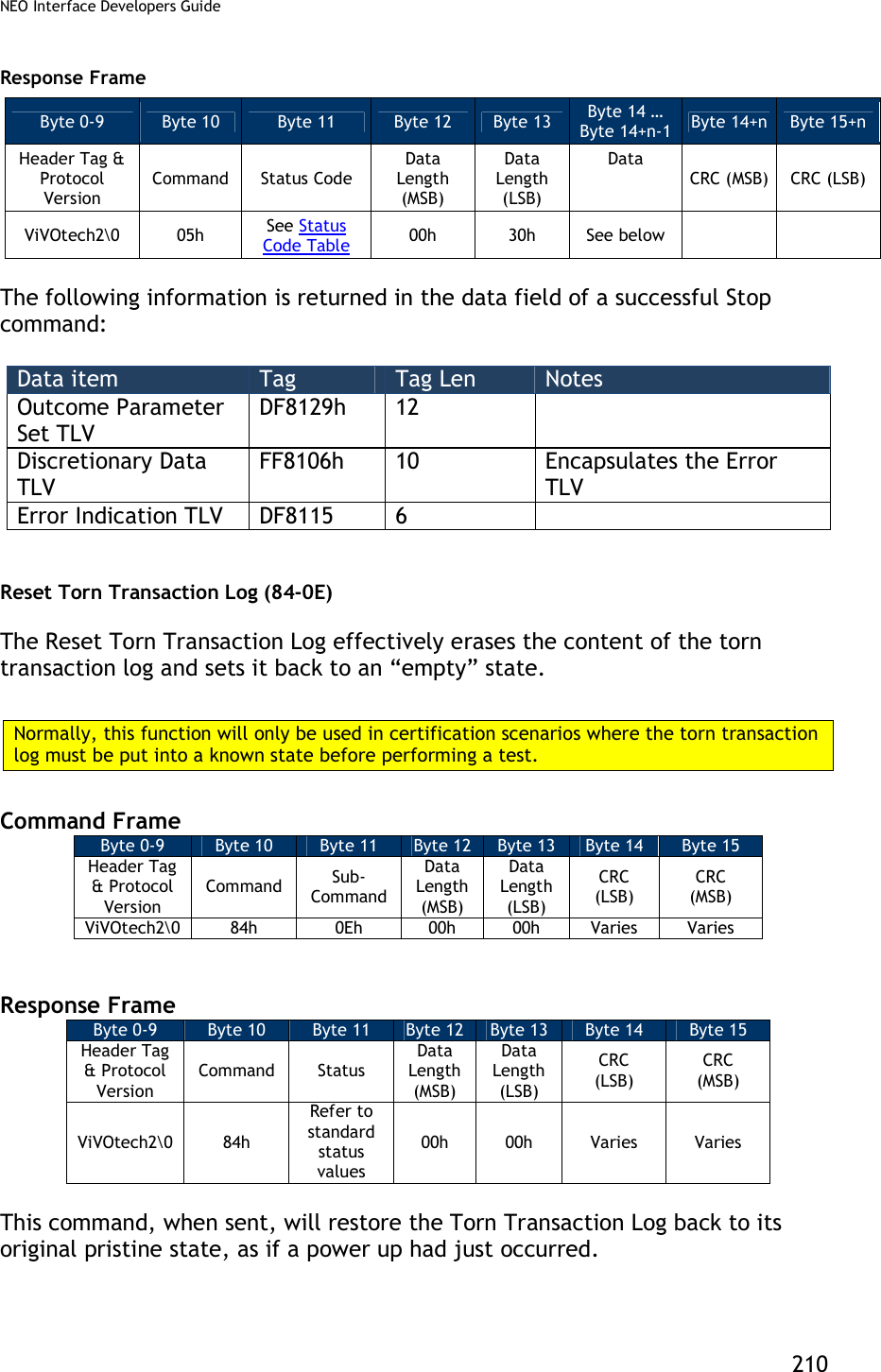
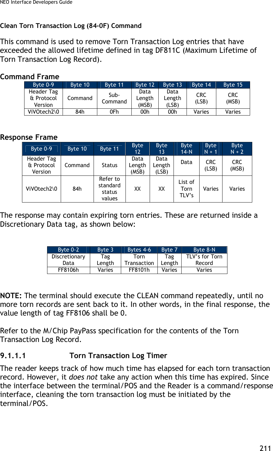
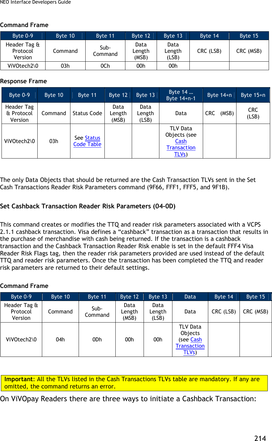
![NEO Interface Developers Guide 212 Periodically, the POS should initiate a cleaning cycle and repeatedly issue the “Clean” command (84-0F) at that point until the reader reports that the Torn Log has been successfully purged. How the POS accomplishes this is beyond the scope of the interface and this document. Visa VCPS Transaction Commands Set Cash Transaction Reader Risk Parameters (04-0C) This command creates or modifies the TTQ and reader risk parameters associated with VCPS 2.1.1 cash transactions. Visa defines a “cash” transaction as a transaction that results in cash only being returned, like a bank machine withdrawal. If the transaction is a cash transaction and the Cash Transaction RR enable is set in the default FFF4 Visa Reader Risk Flags tag, then the reader risk parameters provided are used instead of the default TTQ and reader risk parameters. Once the transaction has been completed the TTQ and reader risk parameters are returned to their default settings. Command Frame Byte 0-9 Byte 10 Byte 11 Byte 12 Byte 13 Byte 14 … Byte 14+n-1 Byte 14 Byte 15 Header Tag & Protocol Version Command Sub-Command Data Length (MSB) Data Length (LSB) Data CRC (LSB) CRC (MSB) ViVOtech2\0 04h 0Ch 00h 00h TLV Data Objects (see Cash Transaction TLVs) Important: All the TLVs listed in the table below are mandatory. If any are omitted, the command returns an error. Table 51: Cash Transaction TLVs Tag Data Object Name and Description Format Length (Bytes) 9F1B Terminal Floor Limit Indicates the floor limit in the terminal in for a Visa Cash or Cashback Transaction (hex). b 4 9F66 Visa Terminal Transaction Qualifier (TTQ) Determines the characteristics of the transaction for a Cash transaction. b 4 FFF1[1] Terminal Contactless Transaction Limit Indicates the floor limit in the terminal for a Visa Cash transaction. n12 6](https://usermanual.wiki/ID-TECH/VP3600/User-Guide-3704675-Page-224.png)
![NEO Interface Developers Guide 213 Tag Data Object Name and Description Format Length (Bytes) FFF4[1] Visa Reader Risk Flags Byte 1 b8 b7 b6 b5 b4 b3 b2 b1 Meaning (0 = disable, 1 = enable) - - - - - - - X Status Check X X X X X X X - RFU Byte 2: b8 b7 b6 b5 b4 b3 b2 b1 Meaning (0 = disable, 1 = enable) - - - - - - - X Transaction Limit Check - - - - - - X - CVM Required Limit Test - - - - - X - - Terminal Floor Limit Check - - - - X - - - Cash Transaction Reader Risk (RR) - - - X - - - - Cashback Reader Risk (RR) - - X - - - - - DRL (Dynamic Reader Limits) RR X X - - - - - - RFU Byte 3 b8 b7 b6 b5 b4 b3 b2 b1 Meaning - - - - - - - X Zero Amount Test 0 = If amount is zero, transaction disallowed 1 = If amount is zero, online cryptogram required in the TTQ (9F66) X Zero Amount Test. If 0, bit 1 is ignored. X X X X X X - RFU b 3 FFF5[1] CVM Required Limit Indicates the CVM required floor limit for a Visa Cash transaction. n12 6 Response Frame Byte 0-9 Byte 10 Byte 11 Byte 12 Byte 13 Byte 14+n Byte 15+n Header Tag & Protocol Version Command Status Code Data Length (MSB) Data Length (LSB) CRC (MSB) CRC (LSB) ViVOtech2\0 04h See Status Code Table Get Cash Transaction Reader Risk Parameters (03-0C) This command returns the TTQ and reader risk parameters that will be used for cash transactions, if enabled.](https://usermanual.wiki/ID-TECH/VP3600/User-Guide-3704675-Page-225.png)
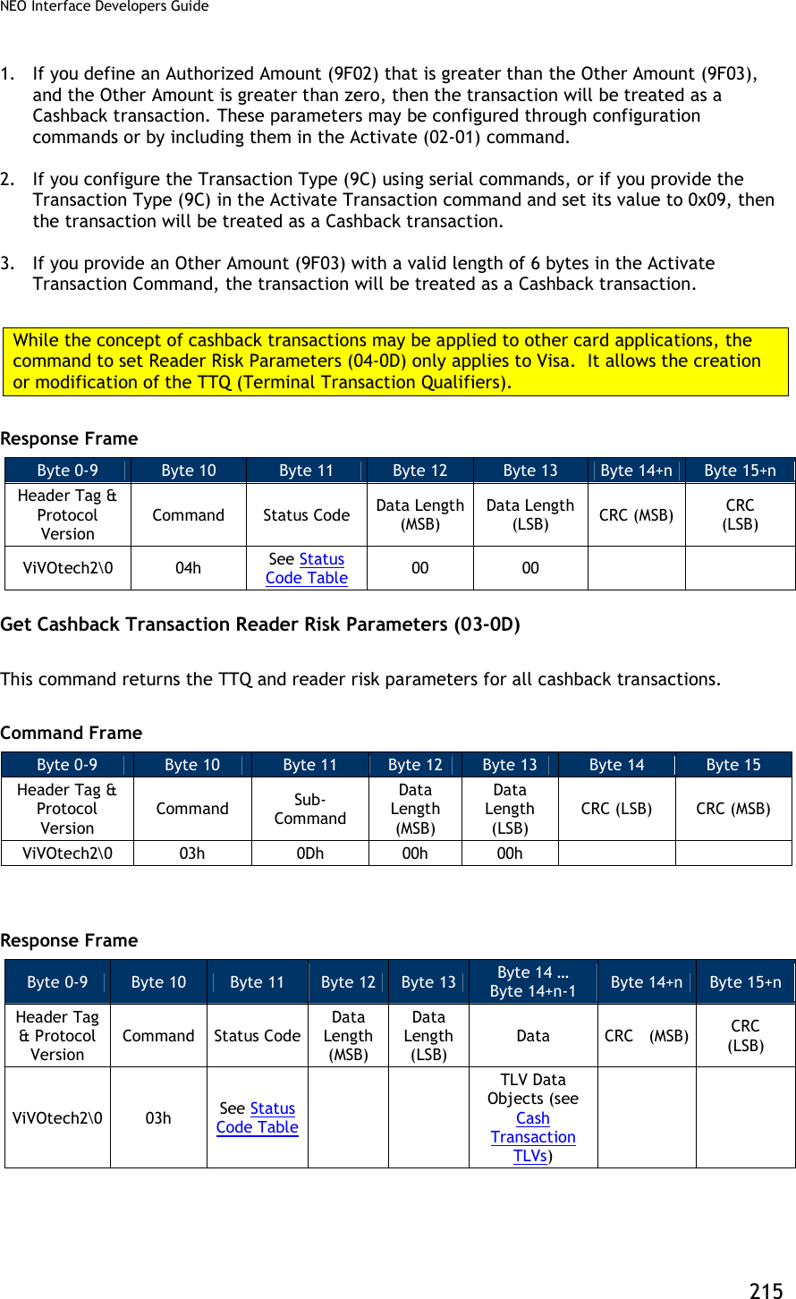
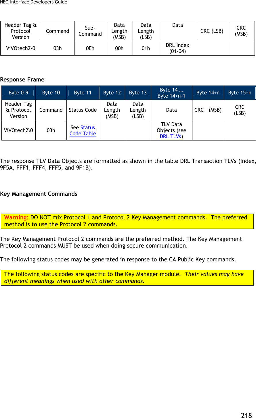
![NEO Interface Developers Guide 216 The only Data Objects that should be returned are the Cash Transaction TLVs sent in the Set Cash Transactions Reader Risk Parameters command (9F66, FFF1, FFF5, and 9F1B). Set DRL Reader Risk Parameters (04-0E) This command creates or modifies the Application Program ID and reader risk parameters for four Dynamic Reader Limit sets. If a Visa card provides an Application Program ID that matches one of the four programmed in the reader DRL sets and the DRL RR enable is set in the default FFF4 Visa Reader Risk Flags tag, the Reader risk parameters for that DRL are used during the transaction. Once the transaction has been completed the Reader risk parameters are returned to their default settings. Command Frame Byte 0-9 Byte 10 Byte 11 Byte 12 Byte 13 Byte 14 … Byte 14+n-1 Byte 14+n Byte 15+n Header Tag & Protocol Version Command Sub-Command Data Length (MSB) Data Length (LSB) Data CRC (LSB) CRC (MSB) ViVOtech2\0 04h 0Eh 00h 01h DRL Index and TLVs Important: All the TLVs listed in the table below are mandatory. If any are omitted, the command returns an error. Table 52: DRL TLVs Tag Data Object Name and Description Format Length (Bytes) None DRL Index This index refers to which DRL set (1 – 4) this data belongs. b 1 9F1B Terminal Floor Limit Changes the Floor Limit for the DRL (hex). b 4 9F5A Application Program ID Determine the characteristics of the transaction for the DRL. b 16 FFF1[1] Terminal Contactless Transaction Limit Indicates the floor limit in the terminal for the DRL. n12 6](https://usermanual.wiki/ID-TECH/VP3600/User-Guide-3704675-Page-228.png)
![NEO Interface Developers Guide 217 Tag Data Object Name and Description Format Length (Bytes) FFF4[1] Visa Reader Risk Flags Byte 1 b8 b7 b6 b5 b4 b3 b2 b1 Meaning (0 = disable, 1 = enable) - - - - - - - X Status Check X X X X X X X - RFU Byte 2: b8 b7 b6 b5 b4 b3 b2 b1 Meaning (0 = disable, 1 = enable) - - - - - - - X Transaction Limit Check - - - - - - X - CVM Required Limit Test - - - - - X - - Terminal Floor Limit Check - - - - X - - - Cash Transaction Reader Risk (RR) - - - X - - - - Cashback Reader Risk (RR) - - X - - - - - DRL (Dynamic Reader Limits) RR X X - - - - - - RFU Byte 3 b8 b7 b6 b5 b4 b3 b2 b1 Meaning - - - - - - - X Zero Amount Test 0 = If amount is zero, transaction disallowed 1 = If amount is zero, online cryptogram required in the TTQ (9F66) X Zero Amount Test. If 0, bit 1 is ignored. X X X X X X - RFU b 3 FFF5[1] CVM Required Limit Indicates the CVM required floor limit for the DRL. n12 6 Response Frame Byte 0-9 Byte 10 Byte 11 Byte 12 Byte 13 Byte 14+n Byte 15+n Header Tag & Protocol Version Command Status Code Data Length (MSB) Data Length (LSB) CRC (MSB) CRC (LSB) ViVOtech2\0 04h See Status Code Table Get DRL Reader Risk Parameters (03-0E) This command returns the Index, Application Program ID, and reader risk parameters for the DRL settings. Command Frame Byte 0-9 Byte 10 Byte 11 Byte 12 Byte 13 Byte 14 … Byte 14+n-1 Byte 14+n Byte 15+n](https://usermanual.wiki/ID-TECH/VP3600/User-Guide-3704675-Page-229.png)
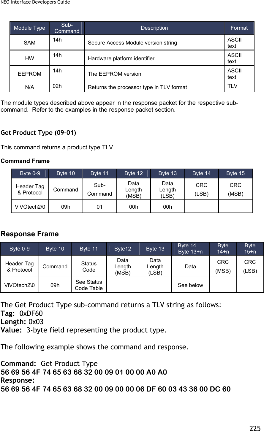
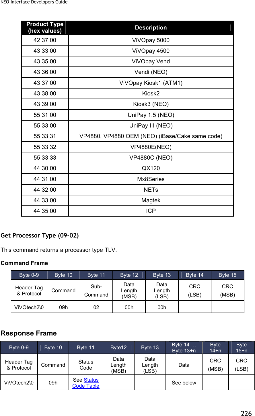
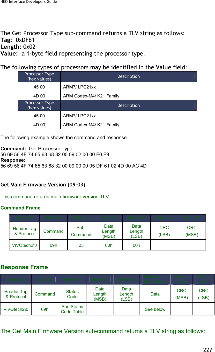
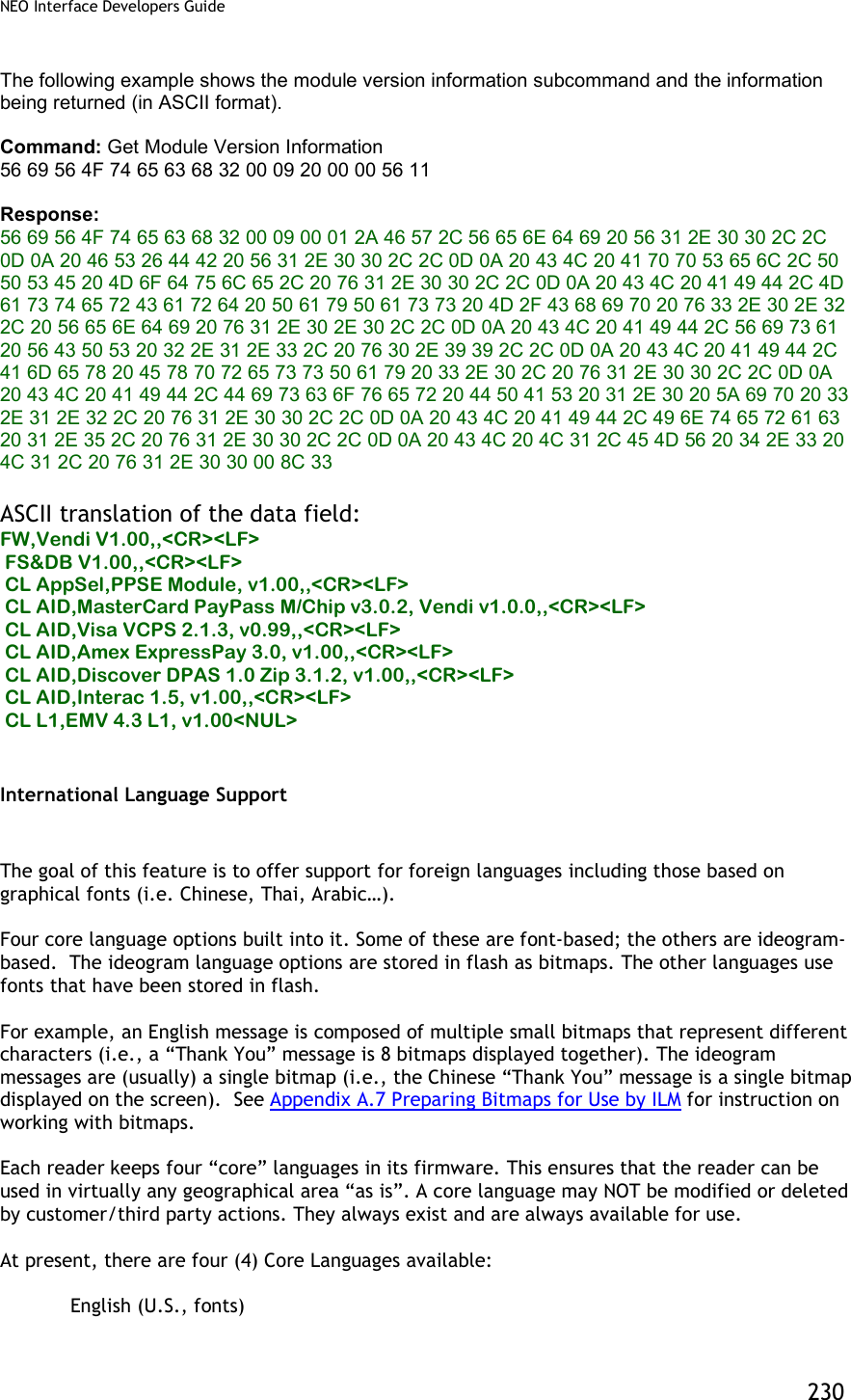
![NEO Interface Developers Guide 224 The implementation of this feature has been simplified for the following reasons: To align more closely with the behavior of the Advanced Reader firmware. To make the version strings more accessible for human readers. To facilitate maintenance of version strings. The following subcommands are available for the Module Version command: Sub-command Description 01h[1] Get Product Type 02h Get Processor Type 03h[1] Get Main Firmware Version 14h Get Hardware Information 20h Get Module Version Information3 [1] Those sub-commands only work on Vendi. Note: All other sub-commands for the Module version command have been deprecated. However, a 0x00 in the sub-command field will return the same result as a 20h sub-command. All other commands will return an “unknown sub-command” error. The table below shows the information that is available and the subcommand that is used to extract that information. The term “module” is used very loosely in the context of the firmware. Module Type Sub-Command Description Format FW 20h The firmware version that is resident in the reader For KioskIII, this verion number shows the firmware version for Lab Verification, it won’t change unless new Lab Verification is done for the certain module. ASCII text CL AppSel 20h Refers to the special application selection module and version. ASCII text CL AID 20h Contactless L2 Application specification/version (since L2 applications are identified by the “application ID”, this type refers to an AID) ASCII text CL AppSpe 20h Contactless L2 Special Application specification/version that not identified by the “application ID” (Example: SmartTap and ApplePay VAS) ASCII text CL L1 20h L1 Interface specification/version ASCII text UI 20h User Interface specification/version ASCII text 3 Previously a subcommand “0x00” was supported. It is being deprecated. However, because some of the ViVOpay internal utilities used that command to determine if the reader was alive, a subcommand of 0x00 will behave exactly the same as a subcommand 0x20 and will not give an error.](https://usermanual.wiki/ID-TECH/VP3600/User-Guide-3704675-Page-236.png)
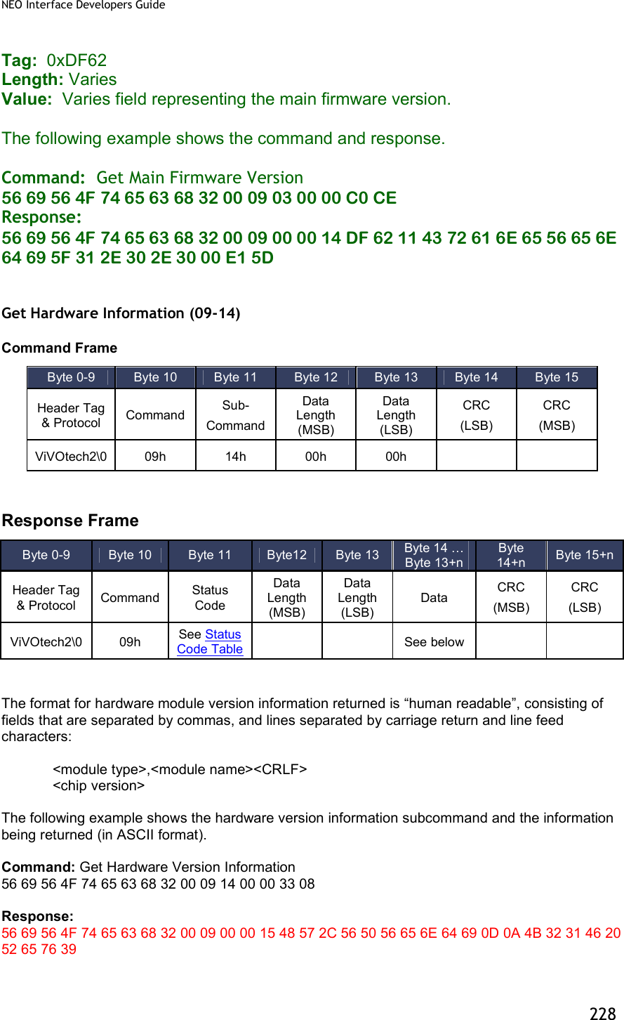
![NEO Interface Developers Guide 229 ASCII translation of the data field: HW,VPVendi<CR><LF> K21F Rev9 ASCII Description HW,VPVendi<CR><LF> K21F Rev9 Vendi HW,VPUnipayIII<CR><LF> K21F Rev9 Unipay III HW,VPUnipay1.5<CR><LF> K21F Rev2 Unipay 1.5 Get Module Version Information (09-20) For KioskIII, this verion number shows the modules version for Lab Verification, it won’t change unless new Lab Verification is done for the certain module. So it may not be consistent with the result of “Get ViVOpay Firmware Version (29-00)” and “Get Main Firmware Version (09-03)” Command Frame Response Frame If there is an error, the appropriate Status Code will be returned with an empty Data field (Data Length = 0000h). The format for module version information returned is “human readable”, consisting of fields that are separated by commas, and lines separated by carriage return and line feed characters: <module type>,<module name and spec. version>,[<implementation version>],<CRLF> Byte 0-9 Byte 10 Byte 11 Byte 12 Byte 13 Byte 14 Byte 15 Header Tag & Protocol Command Sub- Command Data Length (MSB) Data Length (LSB) CRC (LSB) CRC (MSB) ViVOtech2\0 09h 20h 00h 00h Byte 0-9 Byte 10 Byte 11 Byte12 Byte 13 Byte 14 … Byte 13+n Byte 14+n Byte 15+n Header Tag & Protocol Command Status Code Data Length (MSB) Data Length (LSB) Data CRC (MSB) CRC (LSB) ViVOtech2\0 09h See Status Code Table See below](https://usermanual.wiki/ID-TECH/VP3600/User-Guide-3704675-Page-241.png)
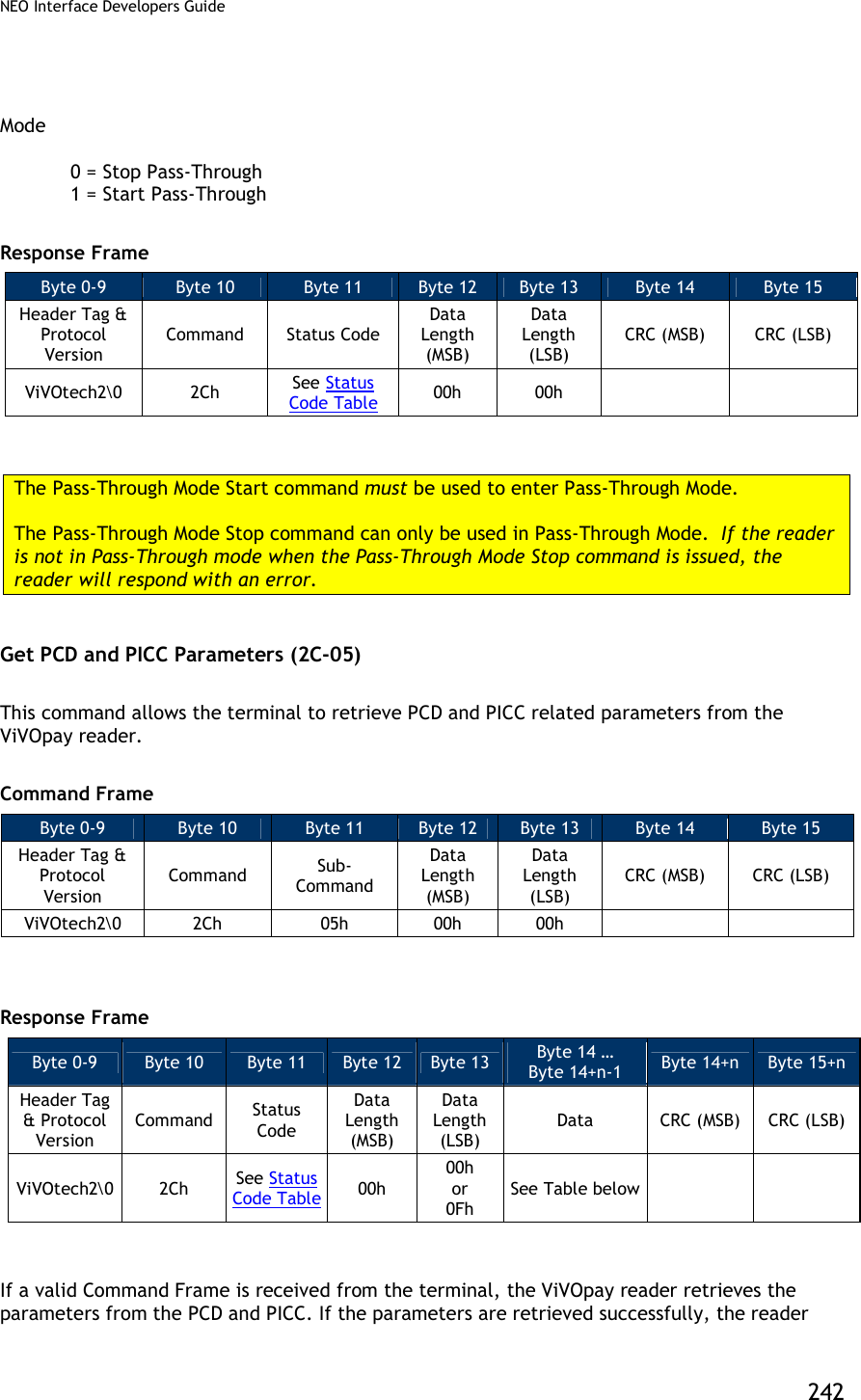
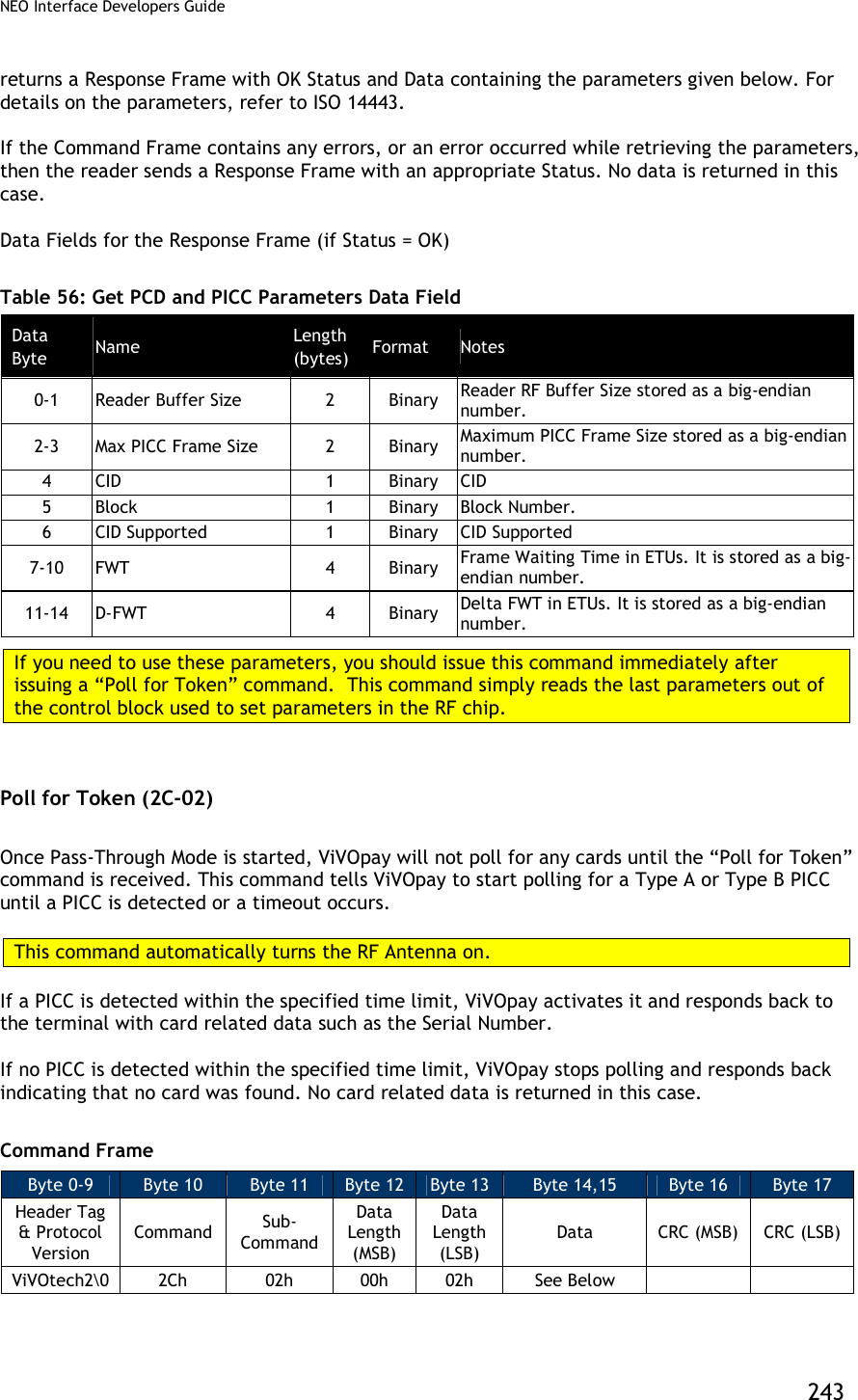
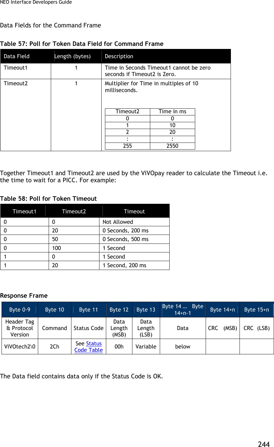
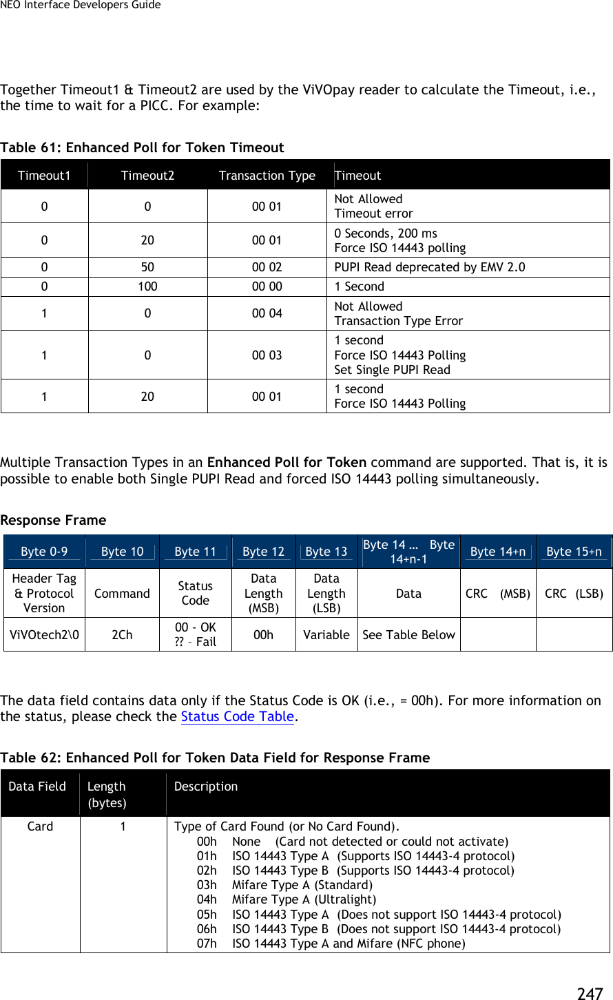
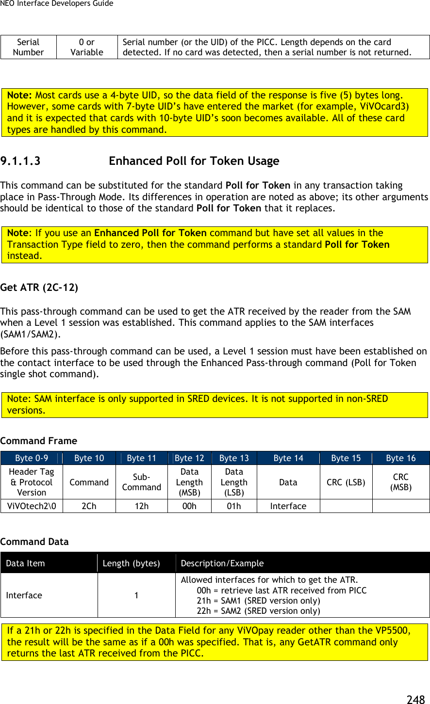
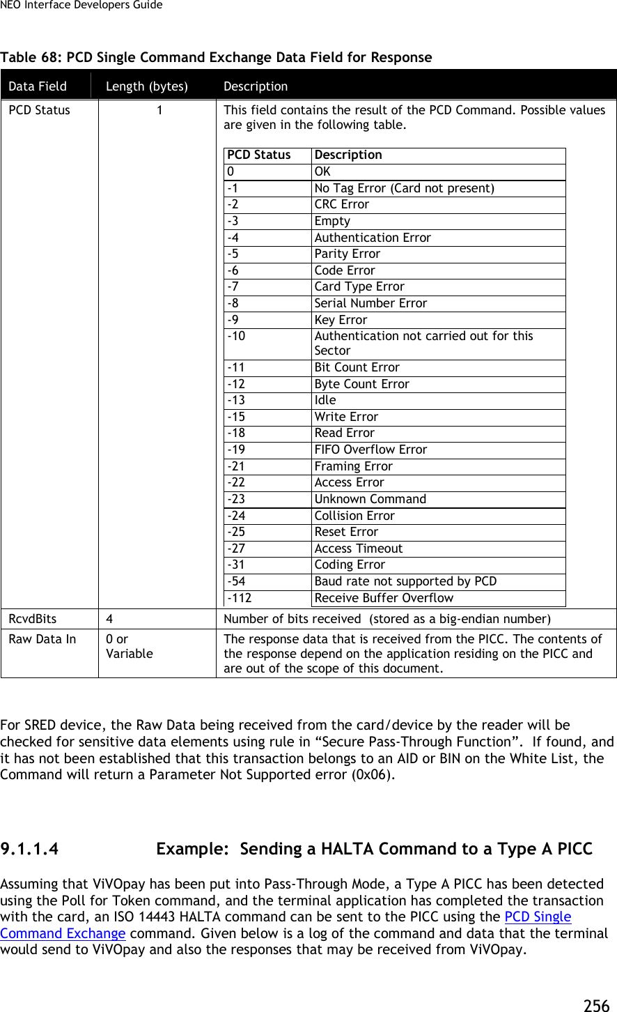
![NEO Interface Developers Guide 245 Table 59: Poll for Token Data Field for Response Frame (Status Code is OK) Data Field Length (bytes) Description Card 1 Type of Card Found (or No Card Found). 00h None (Card Not Detected or Could not Activate) 01h ISO 14443 Type A (Supports ISO 14443-4 Protocol) 02h ISO 14443 Type B (Supports ISO 14443-4 Protocol) 03h Mifare Type A (Standard) 04h Mifare Type A (Ultralight) 05h ISO 14443 Type A (Does not support ISO 14443-4 Protocol) 06h ISO 14443 Type B (Does not support ISO 14443-4 Protocol) 07h ISO 14443 Type A and Mifare (NFC phone) 08h Felica 09h RCTIF Type B Prim Serial Number 0 or Variable Serial Number (or the UID) of the PICC. Length depends on the Card Detected. If no card was detected, then a Serial Number is not returned. Note: Most cards use a 4-byte UID, so the data field of the response is five (5) bytes long. However, some cards with 7-byte UID’s have entered the market (for example, ViVOcard3) and it is expected that cards with 10-byte UID’s will soon become available. All of these card types are handled by this command. Enhanced Poll for Token (2C-0C) Once Pass-Through Mode is started, ViVOpay waits until the Poll for Token command is received. This command tells ViVOpay to start polling for a Type A or Type B PICC until a PICC is detected or a timeout occurs. This command automatically turns the RF Antenna on. Note: (For Kiosk III only) This command and Poll for Token command(2c-02) can be canceled by command (05-01).for example: 1. Cancel Poll for Token command, [TX] - 56 69 56 4F 74 65 63 68 32 00 2C 02 00 02 05 20 85 B8 [TX] - 56 69 56 4F 74 65 63 68 32 00 05 01 00 00 92 EF [RX] - 56 69 56 4F 74 65 63 68 32 00 05 00 00 08 DF EF 36 04 00 07 00 00 77 FA 2. Cancel Enhanced Poll for Token command [TX] - 56 69 56 4F 74 65 63 68 32 00 2C 0C 00 04 05 00 00 01 54 AB [TX] - 56 69 56 4F 74 65 63 68 32 00 05 01 00 00 92 EF [RX] - 56 69 56 4F 74 65 63 68 32 00 05 00 00 08 DF EF 36 04 00 07 00 00 77 FA If a PICC is detected within the speified time limit, ViVOpay activates it and responds back to the terminal with card related data, such as the Card Type and Serial Number (UID). If no PICC is detected within the specified time limit, ViVOpay stops polling and responds back indicating that no card was found. No card related data is returned in this case.](https://usermanual.wiki/ID-TECH/VP3600/User-Guide-3704675-Page-257.png)
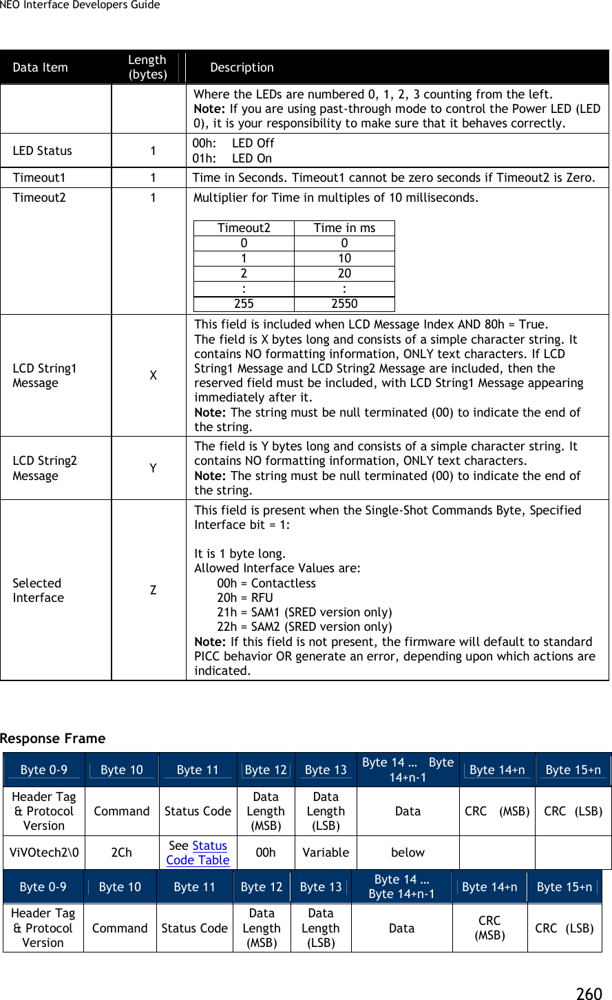
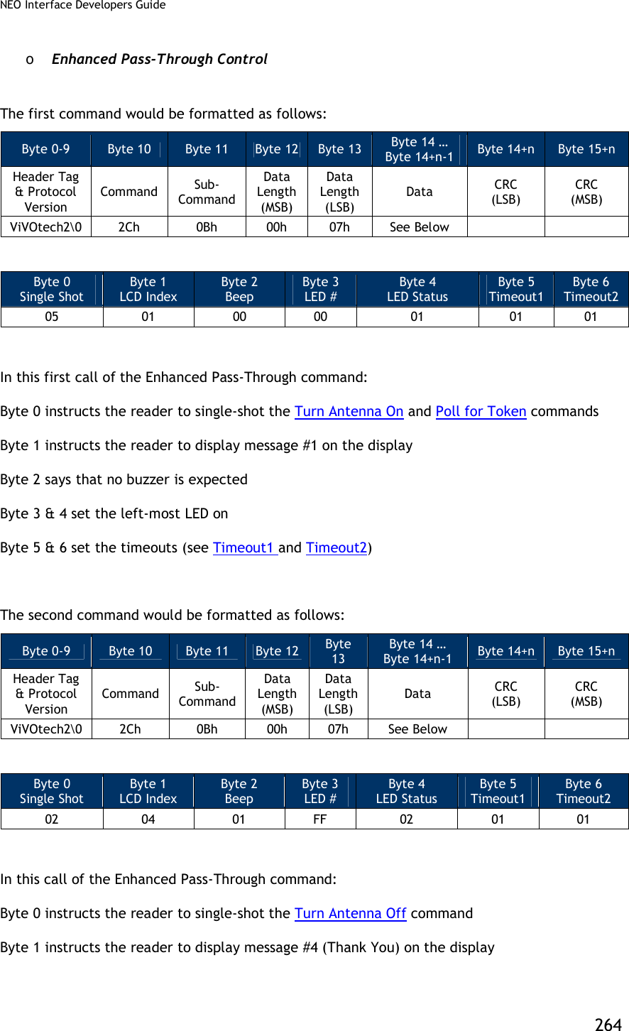
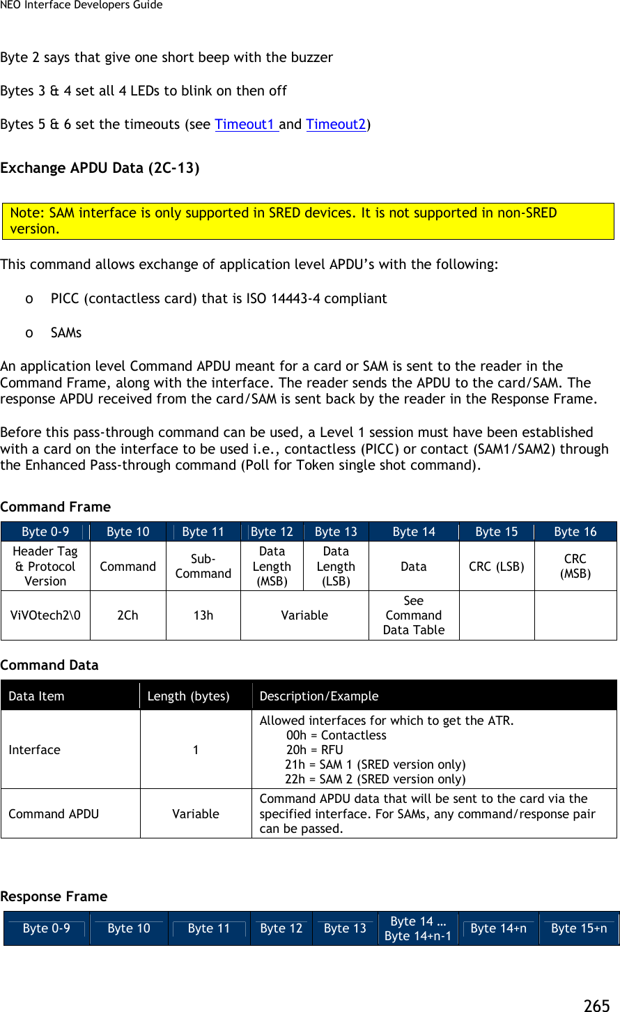
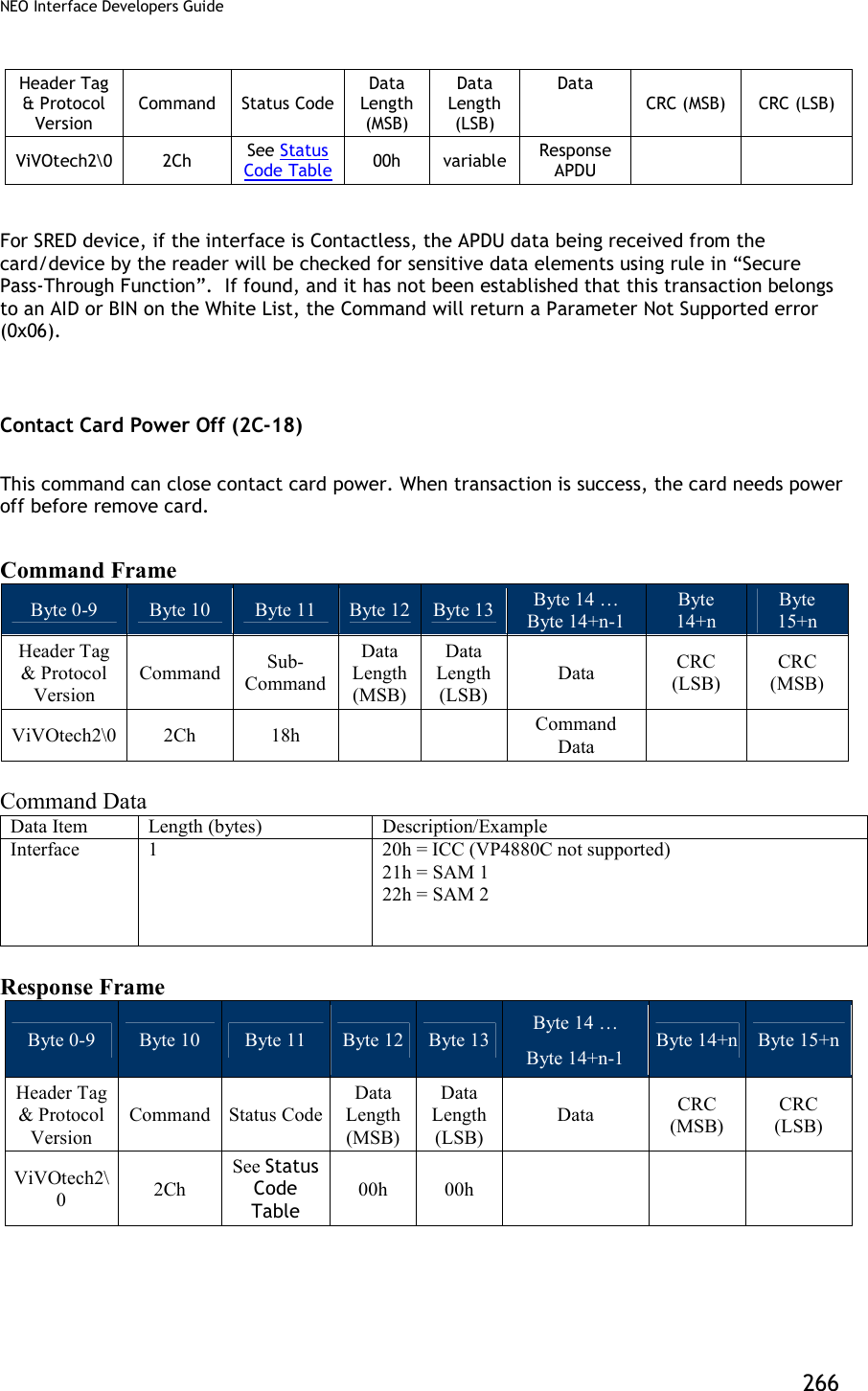
![NEO Interface Developers Guide 257 The following serial data may be exchanged between a terminal/PC and a ViVOpay reader: Table 69: Halt a Command Exchange Between Terminal/PC and Reader Terminal ViVOpay Command Frame (“PCD Single Command Exchange”, PcdTransceive, 106 ETUs, [FlushFiFO=0, DisableDF=0], ChanRedReg=07) “ViVOtech2\0” 2Ch 04h 00h 09h 1Eh 00h 00h 00h 6Ah 00h 07h 50h 00h <CRC><CRC> Response Frame (OK, NoTagError, RcvdBits=0) “ViVOtech2\0” 2Ch 00h 00h 05h FFh 00h 00h 00h 00h <CRC><CRC> High Level Halt Command (2C-09) This command instructs the ViVOpay reader to send a HALT command to the card and can be used for any Type A or Type B card. This command can only be used once the reader has been put in Pass-Through mode and the “Poll for Token” command has indicated that a Card is present. Command Frame Byte 0-9 Byte 10 Byte 11 Byte 12 Byte 13 Byte 14 Byte 15 Byte 16 Header Tag & Protocol Version Command Sub-Command Data Length (MSB) Data Length (LSB) Data CRC (MSB) CRC (LSB) ViVOtech2\0 2Ch 09h 00h 01h Card Type Card Type: 0x01 = Type A 0x02 = Type B Response Frame Byte 0-9 Byte 10 Byte 11 Byte 12 Byte 13 Byte 14 Byte 15 Header Tag & Protocol Version Command Status Code Data Length (MSB) Data Length (LSB) CRC (MSB) CRC (LSB) ViVOtech2\0 2Ch See Status Code Table 00h 00h Enhanced Pass-Through Command (2C-0B) This command instructs the reader to carry out several tasks while in Pass-Through Mode. This command is ONLY enabled in Pass-Through Mode. If the reader is not in Pass-Through Mode, the reader ignores this command.](https://usermanual.wiki/ID-TECH/VP3600/User-Guide-3704675-Page-269.png)
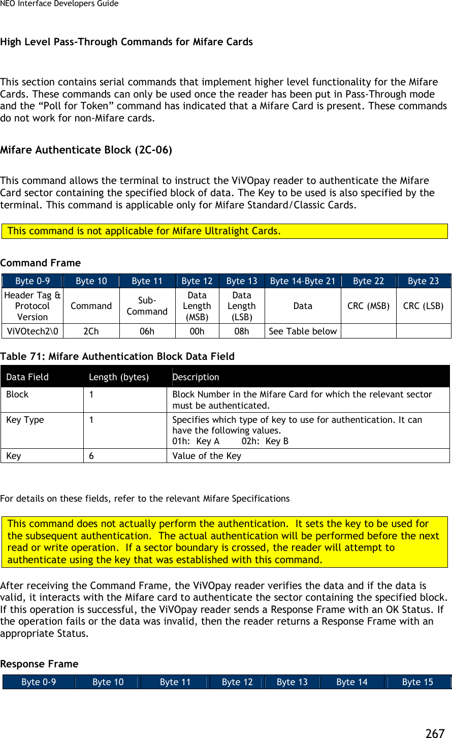
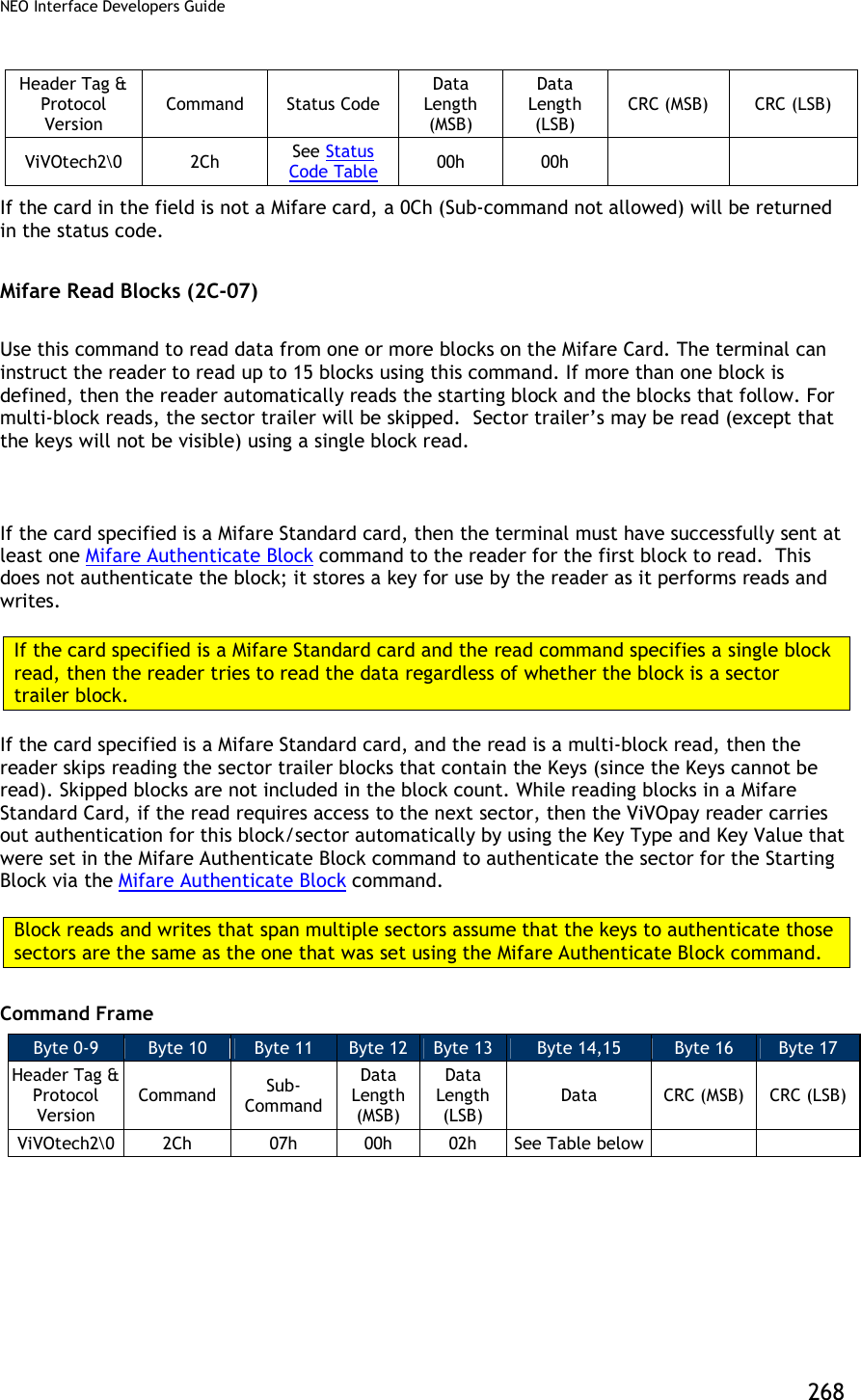
![NEO Interface Developers Guide 269 Table 72: Mifare Read Block Data Field Data Field Length (bytes) Description Card & Block Count 1 Card Type: [Bit 7..4] This can only indicate the following cards Mifare Type A (Standard) Mifare Type A (Ultralight) The values for these card types are defined in the “Poll for Token” command (consider only the lower 4 bits). Block Count: [Bit 3..0] This is the number of 16-byte blocks that are read. The Block Count cannot be greater than 15. This count does not include the skipped blocks if the card is a Mifare Standard card. Start Block 1 This is the card block number from which the reader starts reading. After receiving the Command Frame the ViVOpay reader verifies the parameters. If the parameters are valid, then it reads the data from the card. If this operation is successful, the ViVOpay reader sends a Response Frame containing a Status of OK and the data that was read. If the operation fails or one or more parameters were invalid, then the reader sends a Response Frame containing an appropriate Status, but no data. Response Frame Byte 0-9 Byte 10 Byte 11 Byte 12 Byte 13 Byte 14 … Byte 14+n-1 Byte 14+n Byte 15+n Header Tag & Protocol Version Command Status Code Data Length (MSB) Data Length (LSB) Data CRC (MSB) CRC (LSB) ViVOtech2\0 2Ch See Status Code Table Variable Variable Data Read from Card OR None If the Status is OK, then the Data Length depends on the number of blocks read and the card type. DataLen = Blocks Read * (Bytes per Block for Card). If there was an error or no data was read, then the Data Length is zero. For SRED device, the data being received from the card/device by the reader will be checked for sensitive data elements using rule in “Secure Pass-Through Function”. If found, and it has not been established that this transaction belongs to an AID or BIN on the White List, the Command will return a Parameter Not Supported error (0x06). 9.1.1.12 Reading Mifare Ultralight Cards Mifare Ultralight cards differ from Mifare Cards. For Mifare Standard Cards the block size is 16 bytes. However, for Mifare Ultralight Cards the block (page) size is 4 bytes. When reading](https://usermanual.wiki/ID-TECH/VP3600/User-Guide-3704675-Page-281.png)
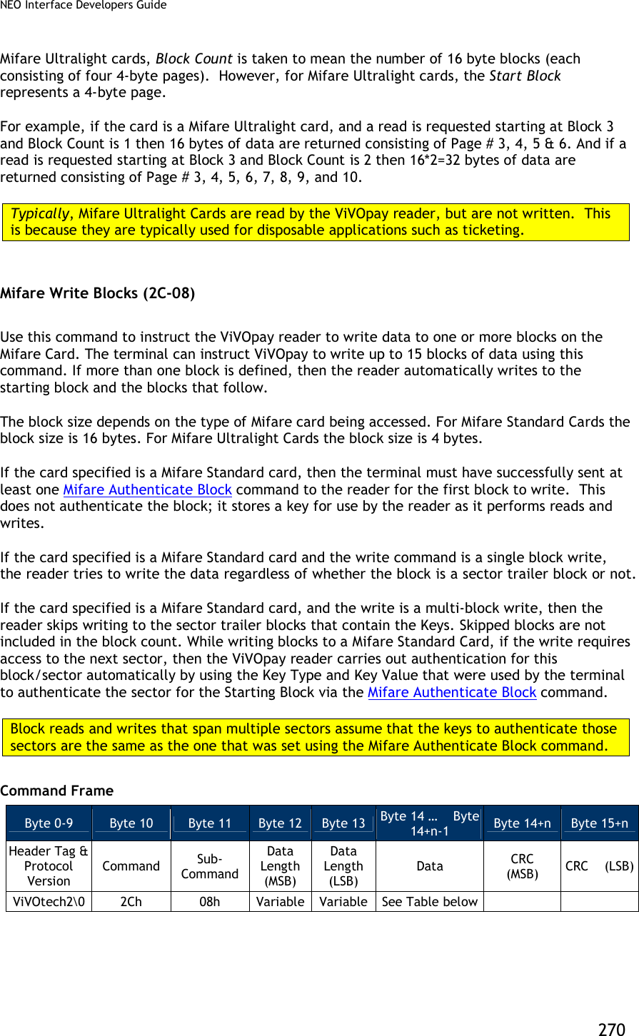
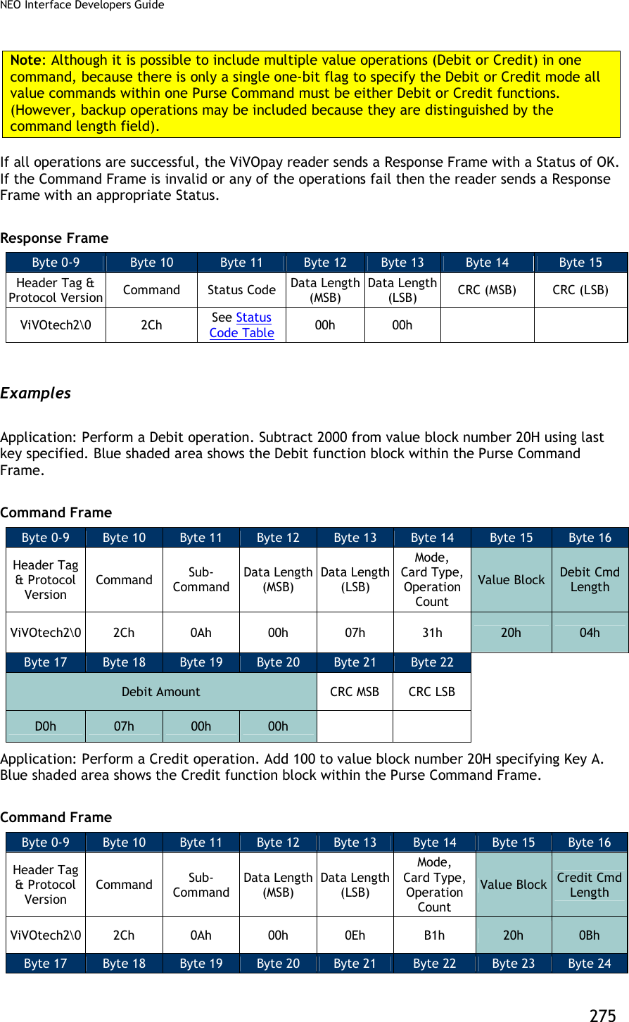
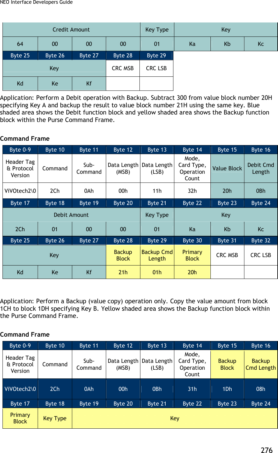
![NEO Interface Developers Guide 271 Table 73: Mifare Write Block Data Field Data Field Length (bytes) Description Card & Block Count 1 Card Type: [Bit 7..4] This can only indicate the following cards Mifare Type A (Standard) Mifare Type A (Ultralight) The values for these card types are defined in the “Poll for Token” command (consider only the lower 4 bits). Block Count: [Bit 3..0] This is the number of blocks that are written. The Block Count cannot be greater than 15. This count does not include the skipped blocks if the card is a Mifare Standard card. Start Block 1 This is the card block number from which the reader starts writing. Data to Write Variable (multiple of block size) Data to write to the Card. The length of the data to be written to the card depends on the number of blocks to be written and the card type. After receiving the Command Frame the ViVOpay reader verifies the parameters. If the parameters are valid, it writes the data to the card. If this operation is successful, the ViVOpay reader sends a Response Frame with a Status of OK. If the Command Frame is invalid or the write operation fails then the reader sends a Response Frame with an appropriate Status. Response Frame Byte 0-9 Byte 10 Byte 11 Byte 12 Byte 13 Byte 14 Byte 15 Header Tag & Protocol Version Command Status Code Data Length (MSB) Data Length (LSB) CRC (MSB) CRC (LSB) ViVOtech2\0 2Ch See Status Code Table 00h 00h Mifare ePurse Command (2C-0A) Use this command to instruct the ViVOpay reader to carry out Debit, Credit and Backup operations on value blocks in a Mifare card. These functions require that the related data blocks be formatted as a value block and that operations and keys used match the defined Access Conditions for that sector. The following illustration shows the format of a value block:](https://usermanual.wiki/ID-TECH/VP3600/User-Guide-3704675-Page-283.png)
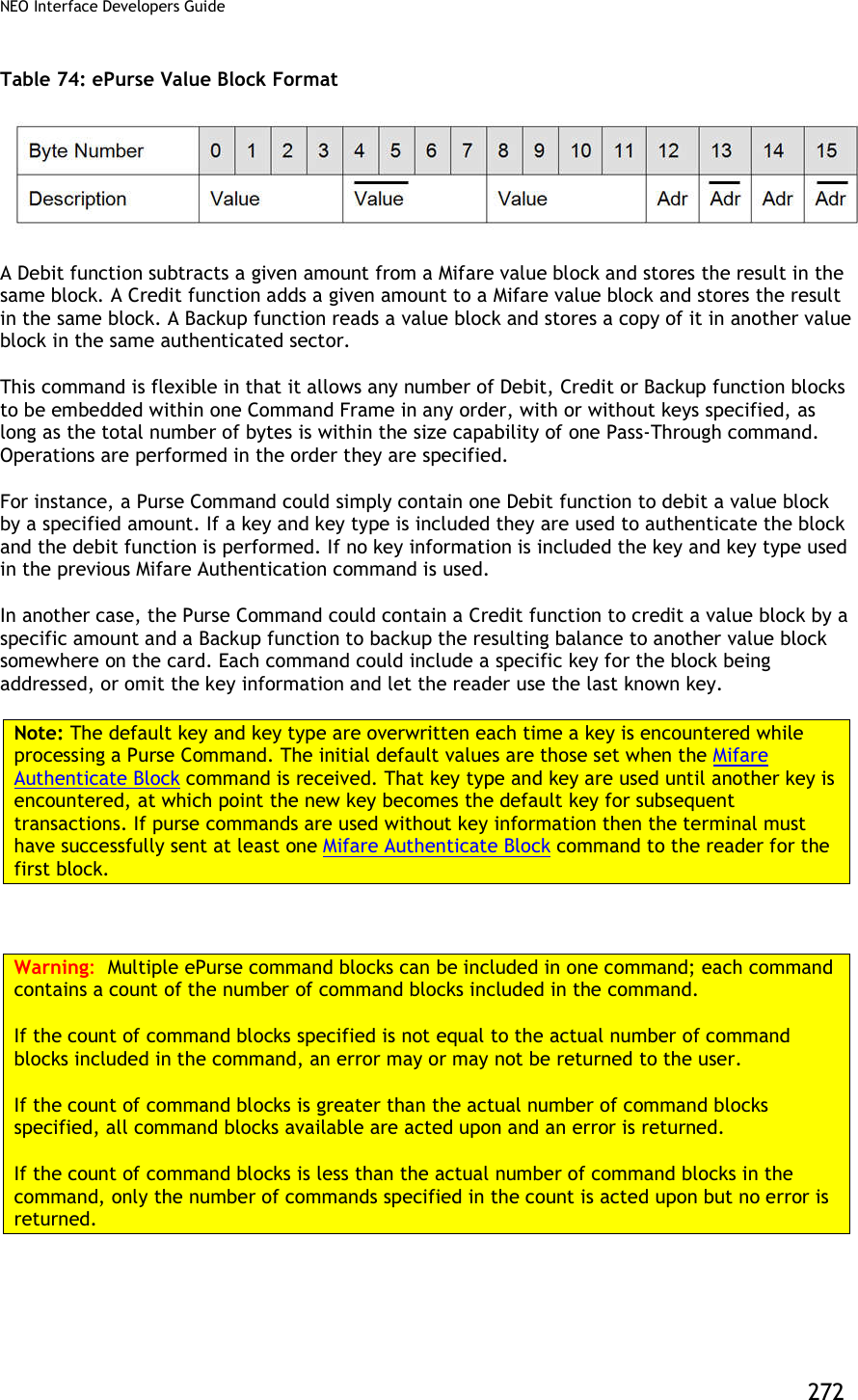
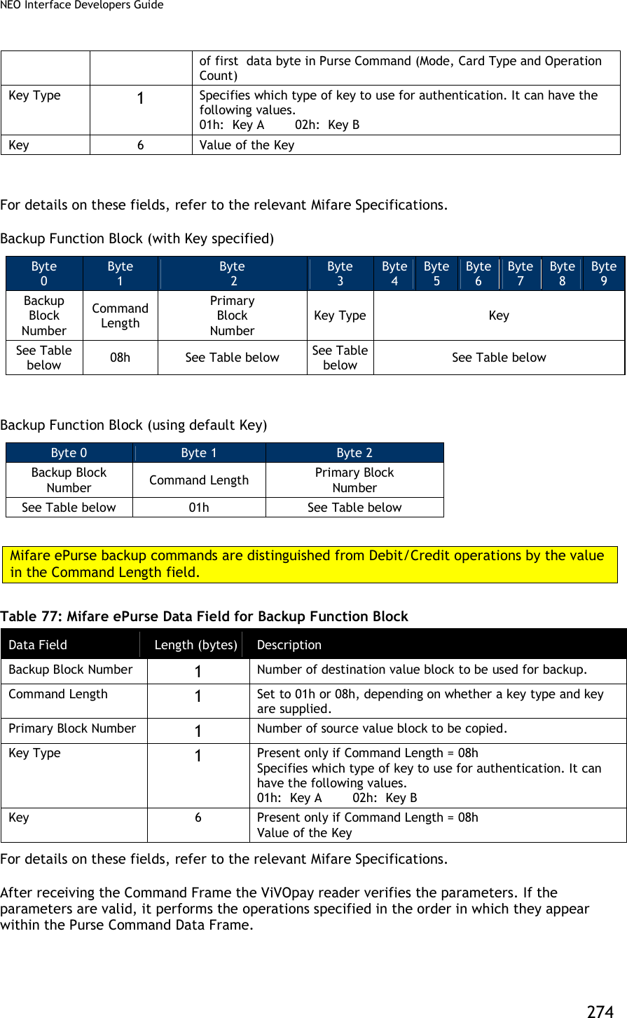
![NEO Interface Developers Guide 273 Command Frame Byte 0-9 Byte 10 Byte 11 Byte 12 Byte 13 Byte 14 … Byte 14+n-1 Byte 14+n Byte 15+n Header Tag & Protocol Version Command Sub-Command Data Length (MSB) Data Length (LSB) Data CRC (MSB) CRC (LSB) ViVOtech2\0 2Ch 0Ah Variable Variable See Table below Table 75: Mifare ePurse Command Data Field Data Field Length (bytes) Description Mode, Card Type & Operation Count 1 7 6 5 4 3 2 1 0 1 = Inc 0 = Dec Card Type Operation Count Increment / Decrement Flag: [Bit 7] Set to 1 instructs reader to Add to (Credit) amount. Set to 0 instructs reader to Subtract from (Debit) amount. Card Type: [Bit 6..4] This can only indicate Mifare Type A (Standard) card (3, as defined in the “Poll for Token” command). Operation Count: [Bit 3..0] This is the number of operation command blocks contained within the rest of the Purse Function data area. Purse Function Blocks Variable [1] Series of any combination of supported Purse Function blocks (Debit/Credit, Backup). Refer to the description of each individual Command Frame below. Debit / Credit Function Block (with Key specified) Byte 0 Byte 1 Byte 2 Byte 3 Byte 4 Byte 5 Byte 6 Byte 7 Byte 8 Byte 9 Byte 10 Byte 11 Byte 12 Value Block Number Command Length Amount Key Type Key 0Bh See Table below See Table See Table Debit / Credit Function Block (using default Key) Byte 0 Byte 1 Byte 2 Byte 3 Byte 4 Byte 5 Value Block Number Command Length Amount 04h See Table Table 76: Mifare ePurse Data Field for Debit/Credit Function Block Data Field Length (bytes) Description Amount 4 Amount to be added (Debit) or subtracted (Credit) in Little-Endian format. Mode of operation (+ or - ) is specified by most significant bit](https://usermanual.wiki/ID-TECH/VP3600/User-Guide-3704675-Page-285.png)
![NEO Interface Developers Guide 277 1Ch 02h Ka Kb Kc Kd Ke Kf Byte 25 Byte 26 CRC MSB CRC LSB High Level Pass-Through Commands for NFC Cards This section contains serial commands that implement higher level functionality for the NFC Cards. These commands do not work for non-NFC cards. NFC Commands (2C-40) This command uses Data[0] in command data field to implement different functions. This command should be used in Pass-Through mode and command with “Poll for a NFC Tag” data should be used first. Command with other data can only be used once the “Poll for a NFC Tag” command has indicated that a NFC tag is present. NFC Commands Byte 0-9 Byte 10 Byte 11 Byte 12 Byte 13 Byte 14 ...Byte 13+n Byte 14+n Byte 15+n Header Tag & Protocol Version Command Sub- Command Data length (MSB) Data length (LSB) Data CRC(MSB) CRC(LSB) ViVOtech2\0 2Ch 40 00 00 See Below Individial commands in NFC command set are distingushed as to parameters in Data field. Table 78: NFC Command Set List Command Data length Command Data Field Description Poll for a NFC Tag 2 Data[0]: FFh Data[1]: Timeout (in second) Tag1 Static Get All Data 1 Data[0]: 11h Tag1 Static Read a Byte 2 Data[0]: 12h Data[1]: Address of the data Tag1 Static Write a Byte 3 Data[0]: 13h Data[1]: Address of the data](https://usermanual.wiki/ID-TECH/VP3600/User-Guide-3704675-Page-289.png)
![NEO Interface Developers Guide 278 Data[2]: Data to be written Tag1 Static Write a Byte NE 3 Data[0]: 14h Data[1]: Address of the data Data[2]: Data to be written Tag1 Dynamic Read a Segment 2 Data[0]: 15h Data[1]: Address of the segment Tag1 Dynamic Read 8 Bytes 2 Data[0]: 16h Data[1]: Address of the data Tag1 Dynamic Write 8 Bytes 10 Data[0]: 17h Data[1]: Address of the data Data[2]~Data[9]: Data to be written Tag1 Dynamic Write 8 Bytes NE 10 Data[0]: 18h Data[1]: Address of the data Data[2]~Data[9]: Data to be written Tag2 Read Data (16 bytes) 2 Data[0]: 21h Data[1]: Address of the data Tag2 Write Data (4 bytes) 6 Data[0]: 22h Data[1]: Address of the data Data[2]~Data[5]: Data to be written Tag2 Select Sect 2 Data[0]: 23h Data[1]: Sect number Tag3 Read Data variable Data[0]: 41h Data[1]: Number of services, value n. Data[2]~Data[2n+1]: Service code list Data[2n+2]: Number of blocks, value m. Data[2n+3....]: Block list, length is 2m~3m Tag3 Write Data variable Data[0]: 42h Data[1]: Number of services, value n.](https://usermanual.wiki/ID-TECH/VP3600/User-Guide-3704675-Page-290.png)
![NEO Interface Developers Guide 279 Data[2]~Data[2n+1]: Service code list Data[2n+2]: Number of blocks, value m. Data[2n+3....]: Block list, length is 2m~3m Data[...]: Block data, length is 16m Tag4 Command variable Data[0]: 0x81 Data[1]~Data[n]: data NFC Response Byte 0-9 Byte 10 Byte 11 Byte 12 Byte 13 Byte 14 ...Byte 13+n Byte 14+n Byte 15+n Header Tag & Protocol Version Command Status Data length (MSB) Data length (LSB) Data CRC(MSB) CRC(LSB) ViVOtech2\0 2Ch See Status Code Table 00 00 See Below Table 79: NFC Command Set Response Data List Command Response Data length Command Response Data Field Description Poll for a NFC Tag variable Data[0]: Card type 00h None (Card Not Detected or Could not Active) 01h ISO 14443 Type A (Supports ISO 14443-4 Protocol) 02h ISO 14443 Type B (Supports ISO 14443-4 Protocol) 03h Mifare Type A (Standard) 04h Mifare Type A (Ultralight) 05h ISO 14443 Type A (Does not support ISO 14443-4 Protocol) 06h ISO 14443 Type B (Does not support ISO 14443-4 Protocol) 07h ISO 14443 Type A and Mifare (NFC phone) 0Ah NFC Tag 1 0Bh NFC Tag 2 0Ch NFC Tag 3 0Dh NFC Tag 4 Data[1...]: Serial Number (or the UID) of the PICC. Length depends on the card detected. If no card was detected, then a Serial Number is not returned. Others variable Returned data from card](https://usermanual.wiki/ID-TECH/VP3600/User-Guide-3704675-Page-291.png)
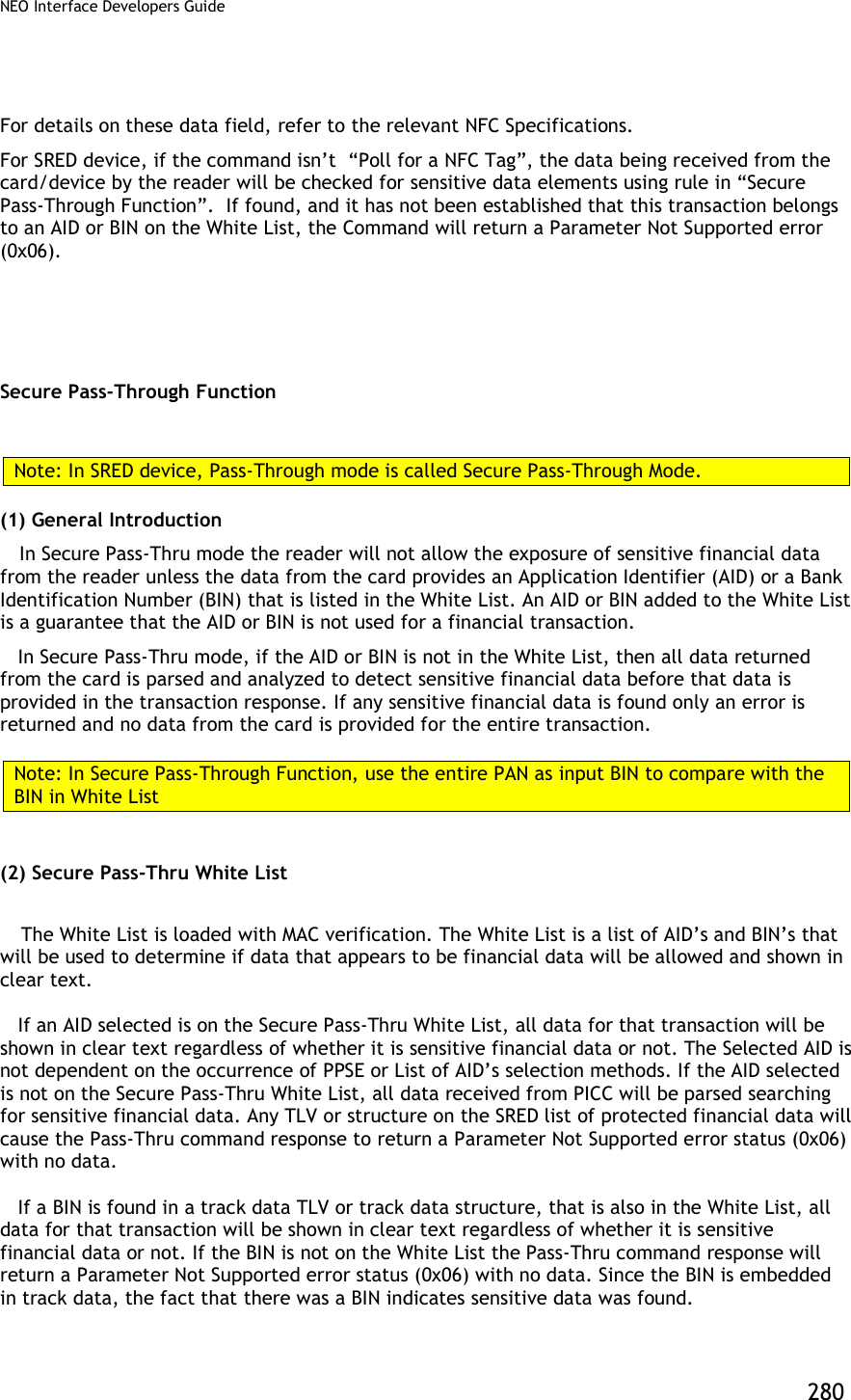
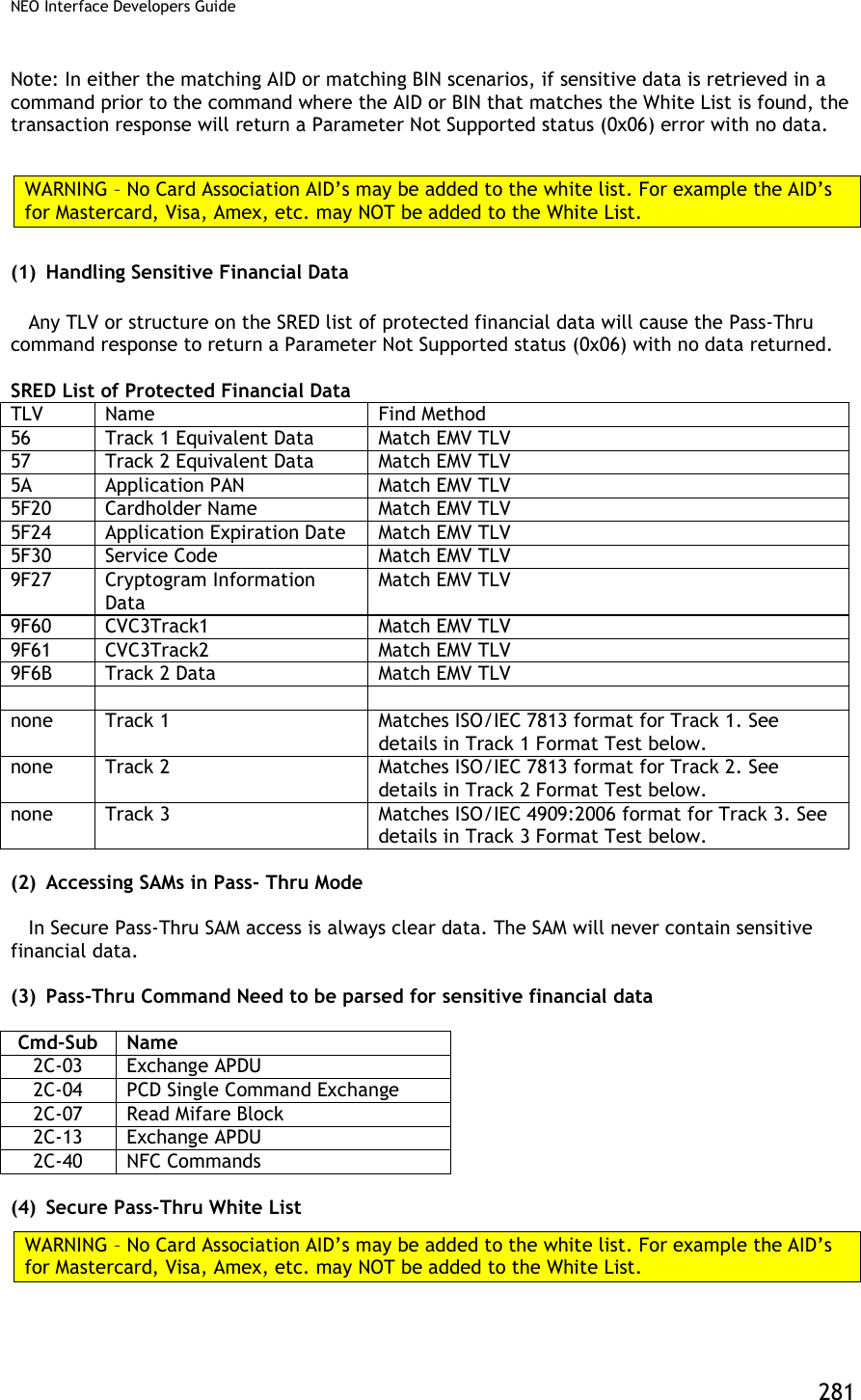
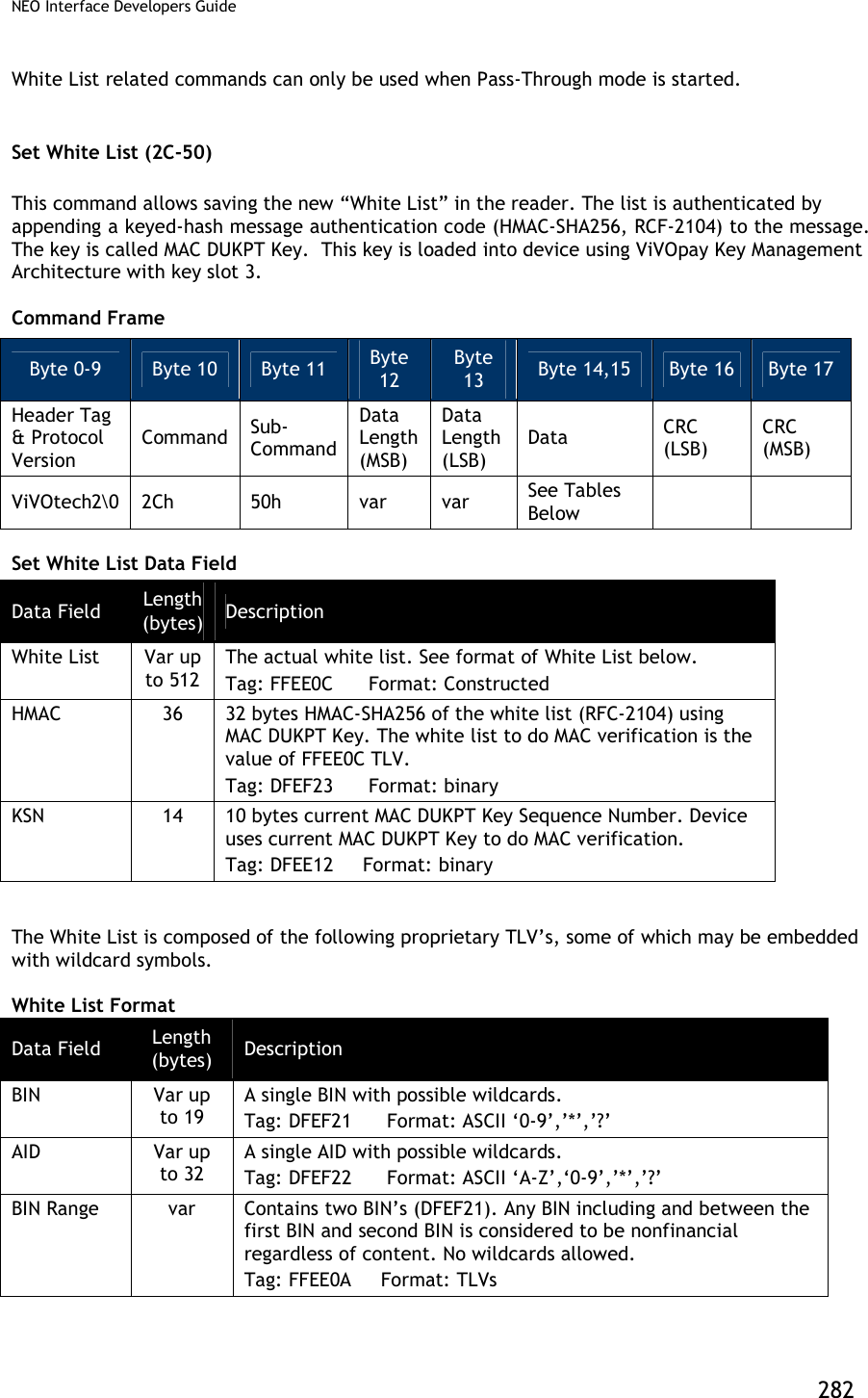
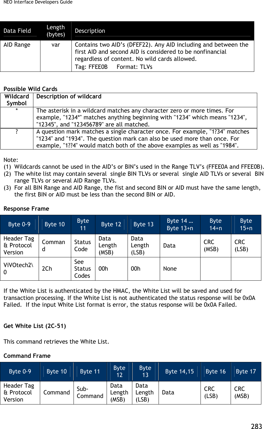
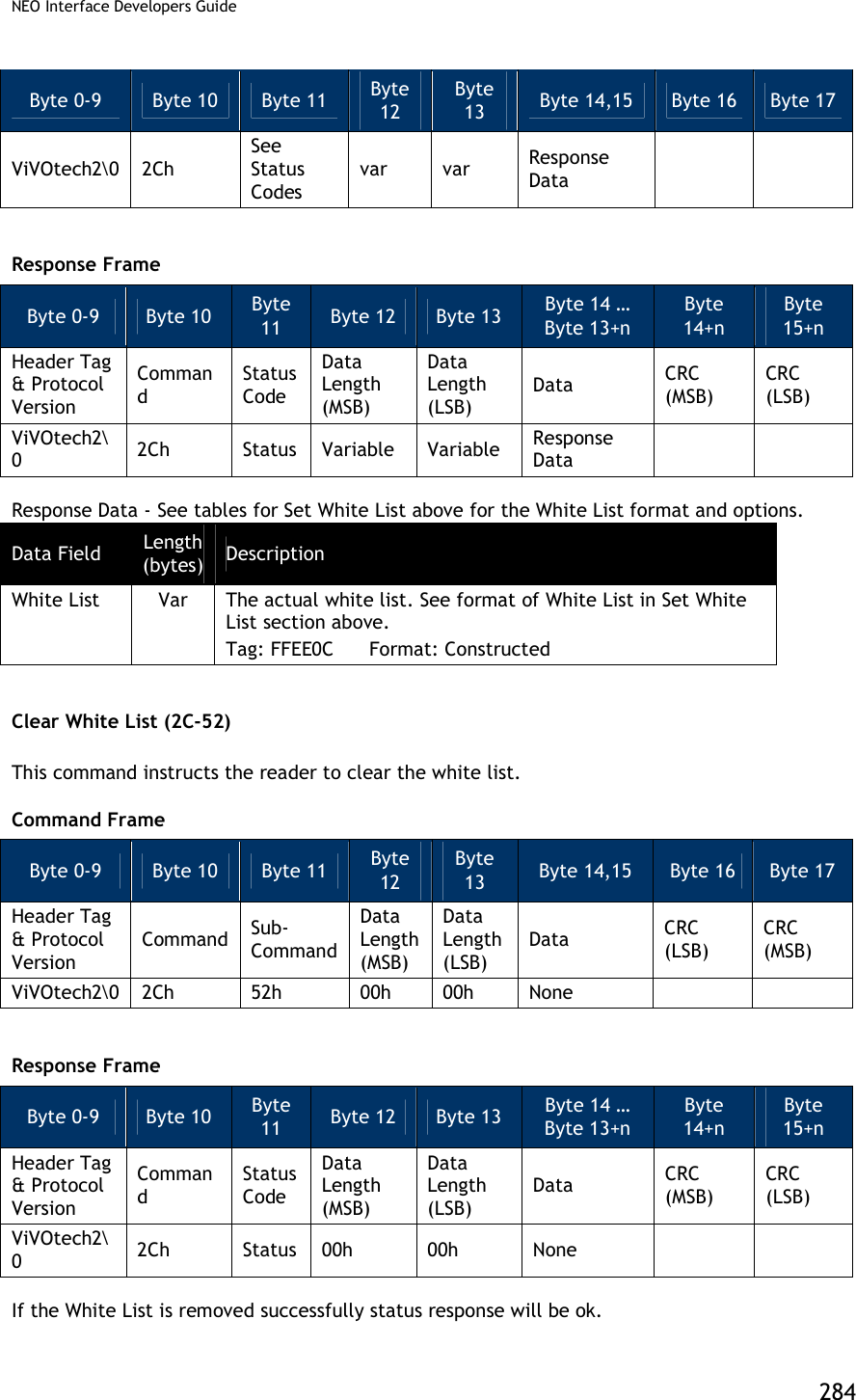
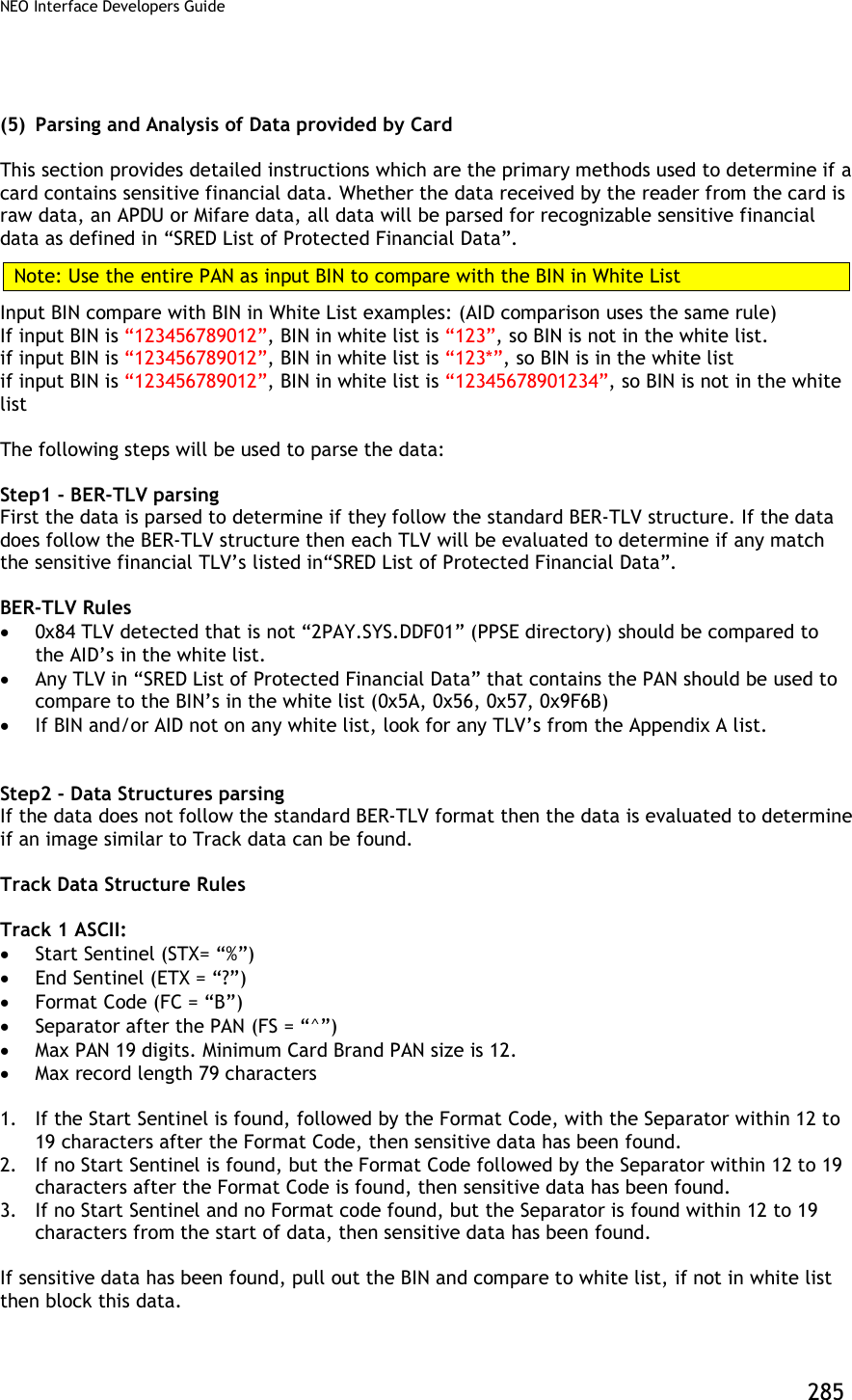
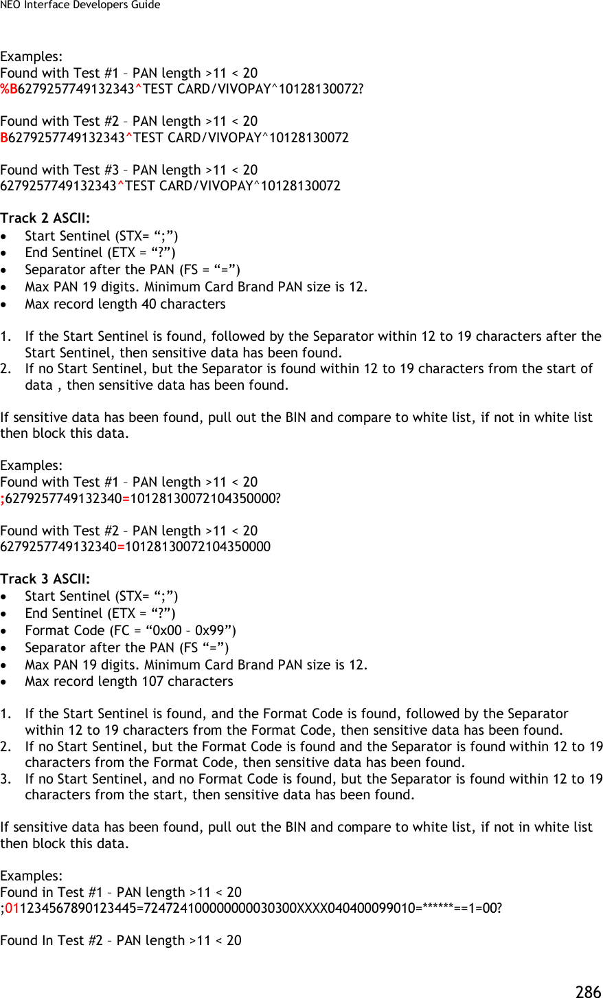
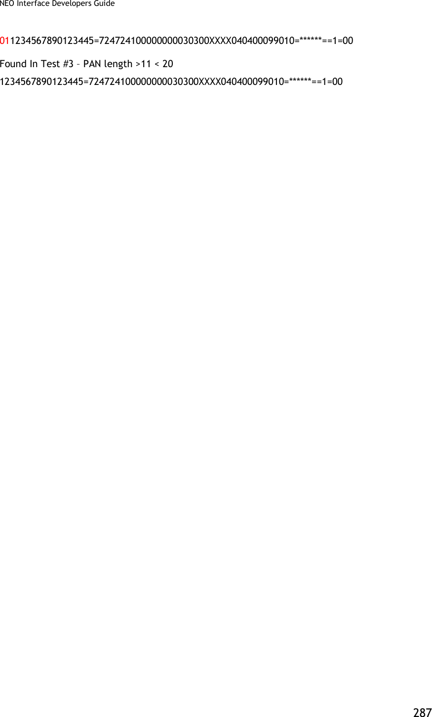
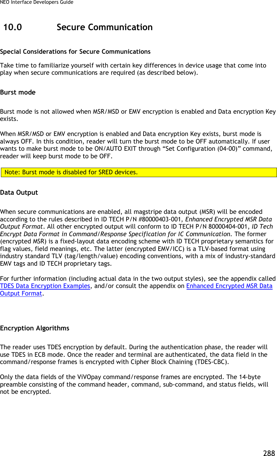
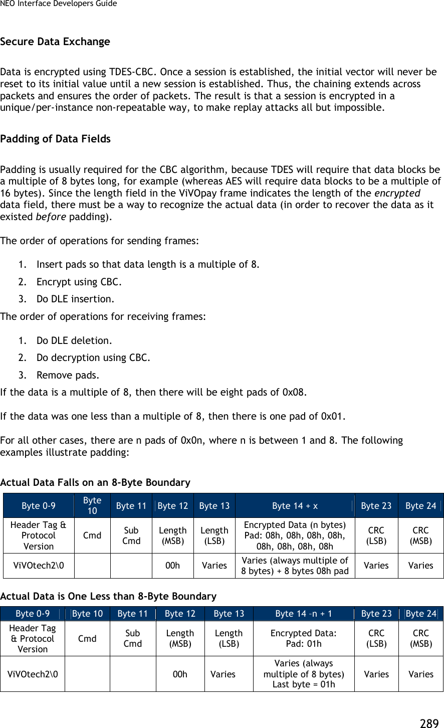
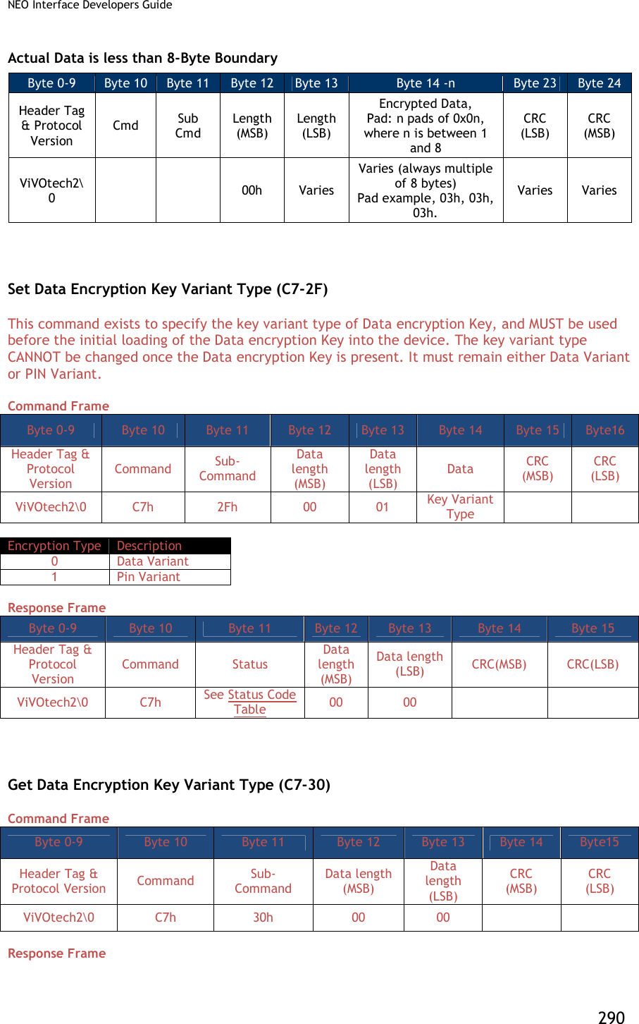
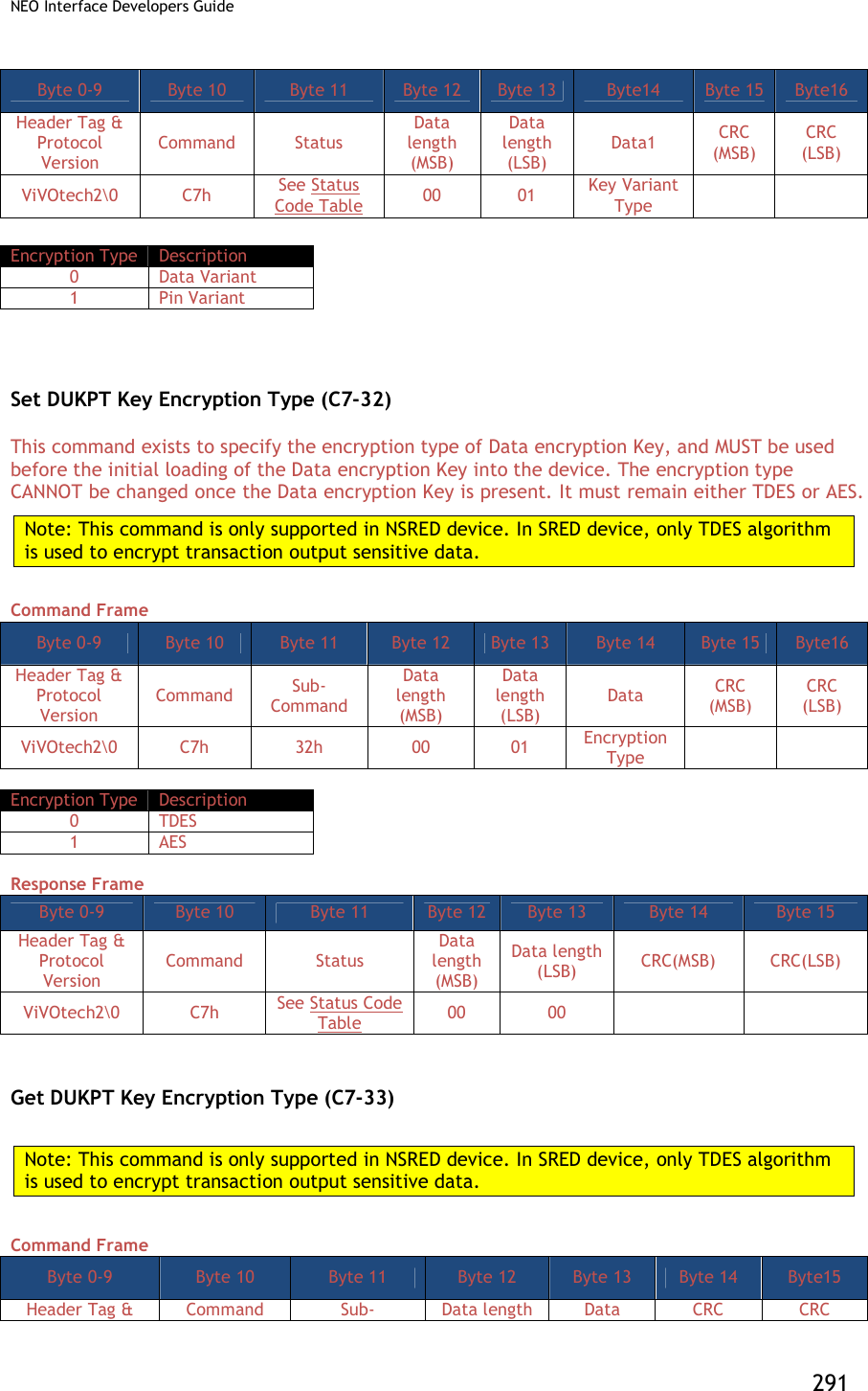
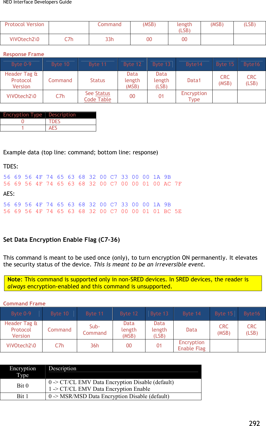
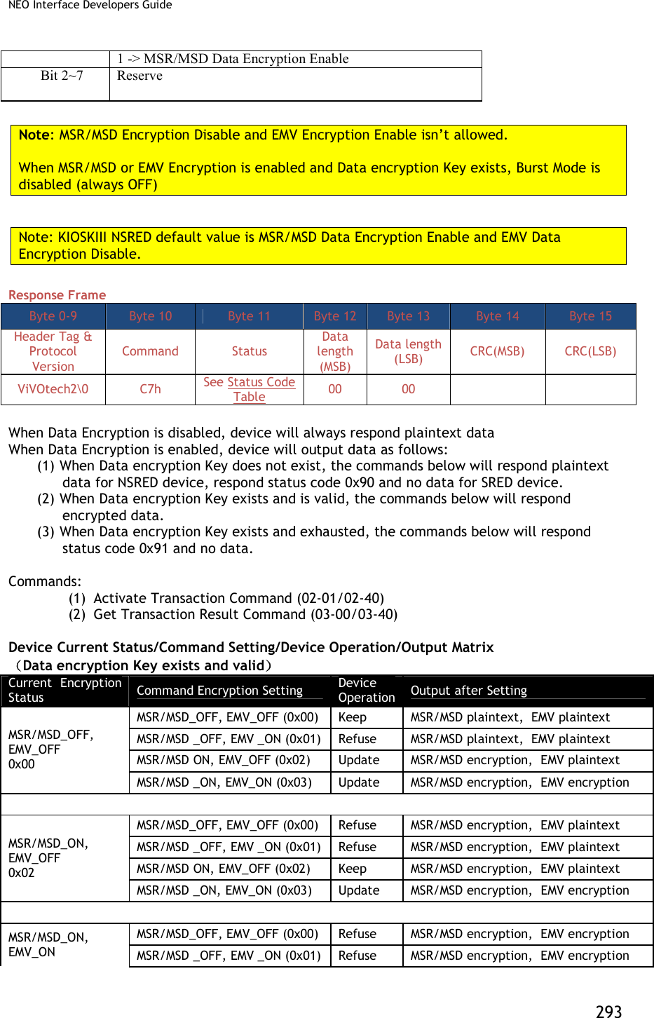
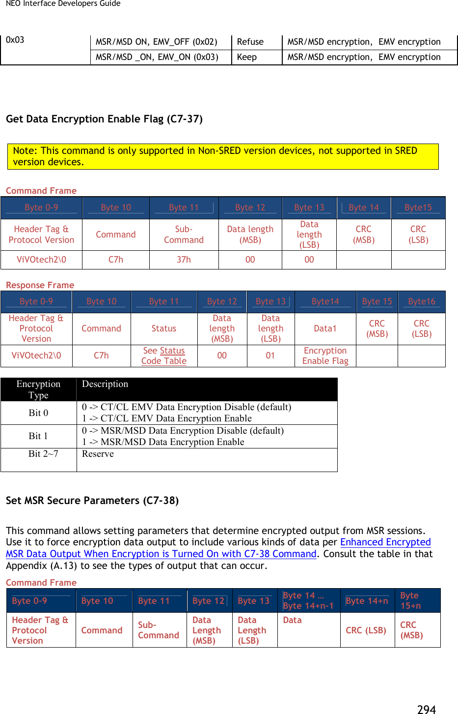
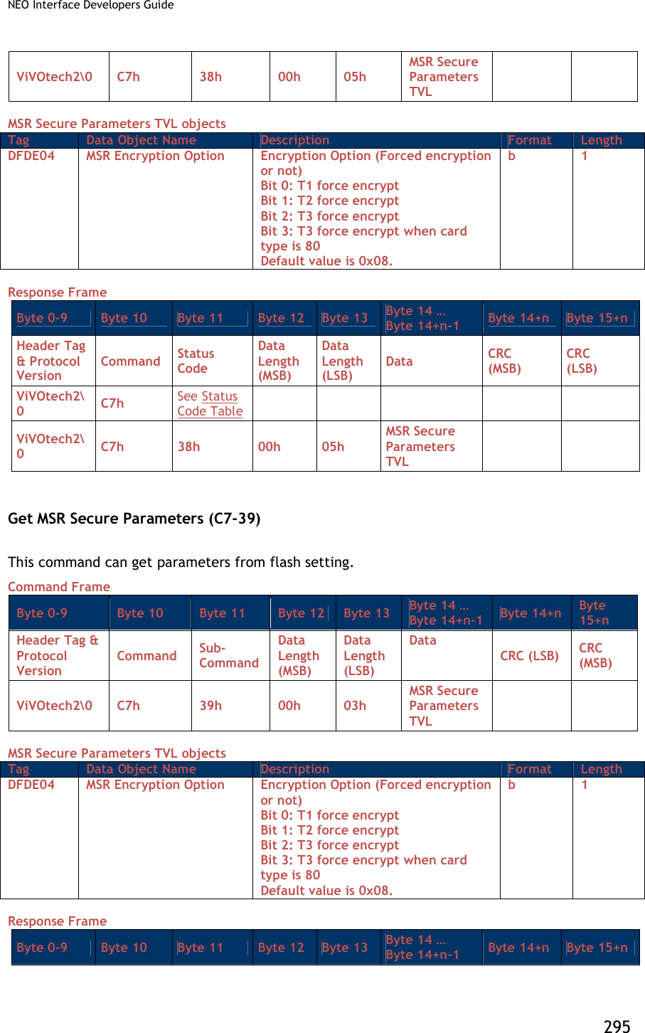
![NEO Interface Developers Guide 296 Header Tag & Protocol Version Command Status Code Data Length (MSB) Data Length (LSB) Data CRC (MSB) CRC (LSB) ViVOtech2\0 C7h See Status Code Table 00h 05h TLV Key Injection and Related Commands Set Remote Key Injection Timeout (C7-2D) Command Frame Byte 0-9 Byte 10 Byte 11 Byte 12 Byte 13 Byte14 Byte 15 Byte 16 Byte17 Header Tag & Protocol Version Command Sub- Command Data length (MSB) Data length (LSB) Data1 Data2 CRC (MSB) CRC (LSB) ViVOtech2\0 C7h 2Dh 00 02 Timeout (MSB) Timeout (LSB) Response Frame Byte 0-9 Byte 10 Byte 11 Byte 12 Byte 13 Byte 14 Byte 15 Header Tag & Protocol Version Command Status Data length (MSB) Data length (LSB) CRC(MSB) CRC(LSB) ViVOtech2\0 C7h See Status Code Table 00 00 Timeout is in second, value scope is [120, 3600]. If timeout, remote key injection is canceled. Get Remote Key Injection Timeout (C7-2E) Command Frame Byte 0-9 Byte 10 Byte 11 Byte 12 Byte 13 Byte 14 Byte15 Header Tag & Protocol Version Command Sub- Command Data length (MSB) Data length (LSB) CRC (MSB) CRC (LSB) ViVOtech2\0 C7h 2Eh 00 00 Response Frame Byte 0-9 Byte 10 Byte 11 Byte 12 Byte 13 Byte14 Byte 15 Byte 16 Byte17 Header Tag & Protocol Version Command Status Data length (MSB) Data length (LSB) Data1 Data2 CRC (MSB) CRC (LSB) ViVOtech2\0 C7h See Status Code Table 00 00 Timeout (MSB) Timeout (LSB) Timeout is in second, value scope is [120, 3600]. If timeout, remote key injection is canceled.](https://usermanual.wiki/ID-TECH/VP3600/User-Guide-3704675-Page-308.png)
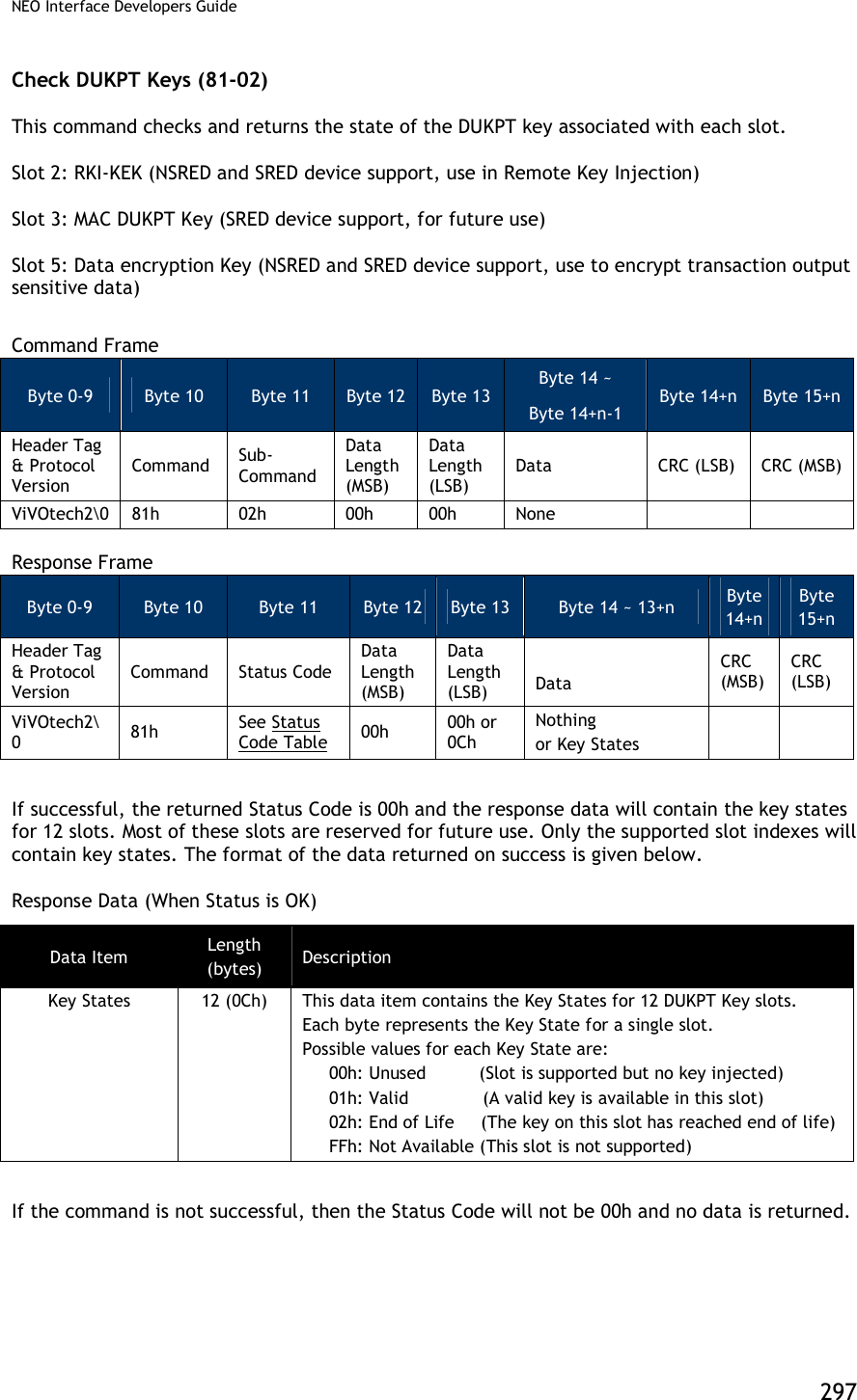
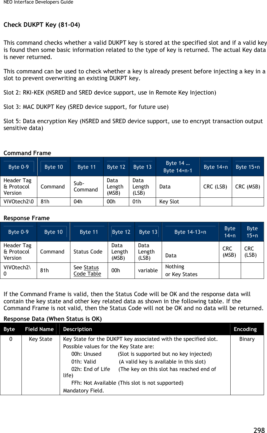
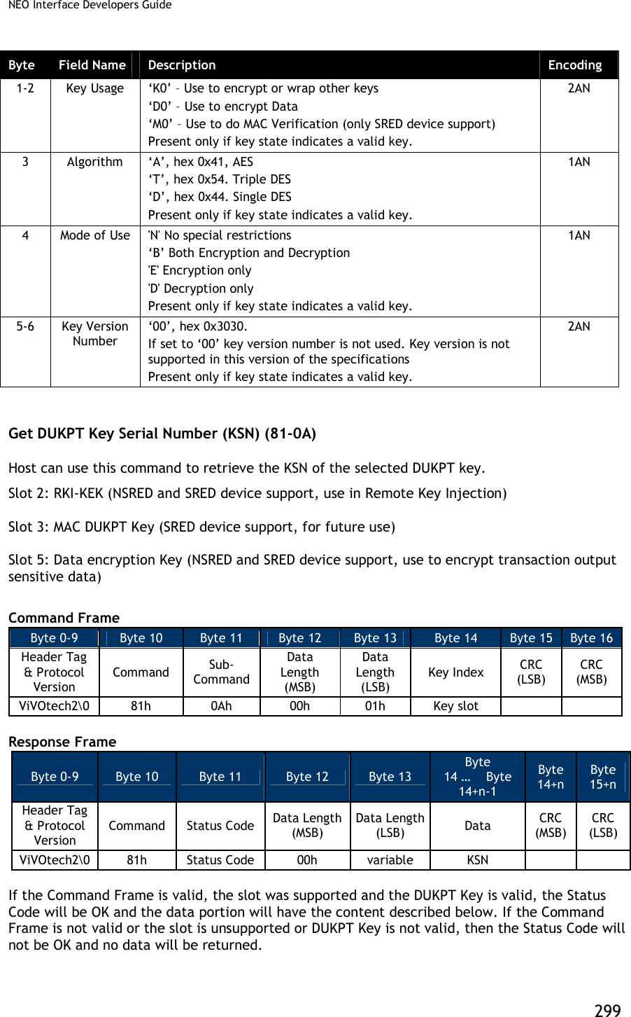
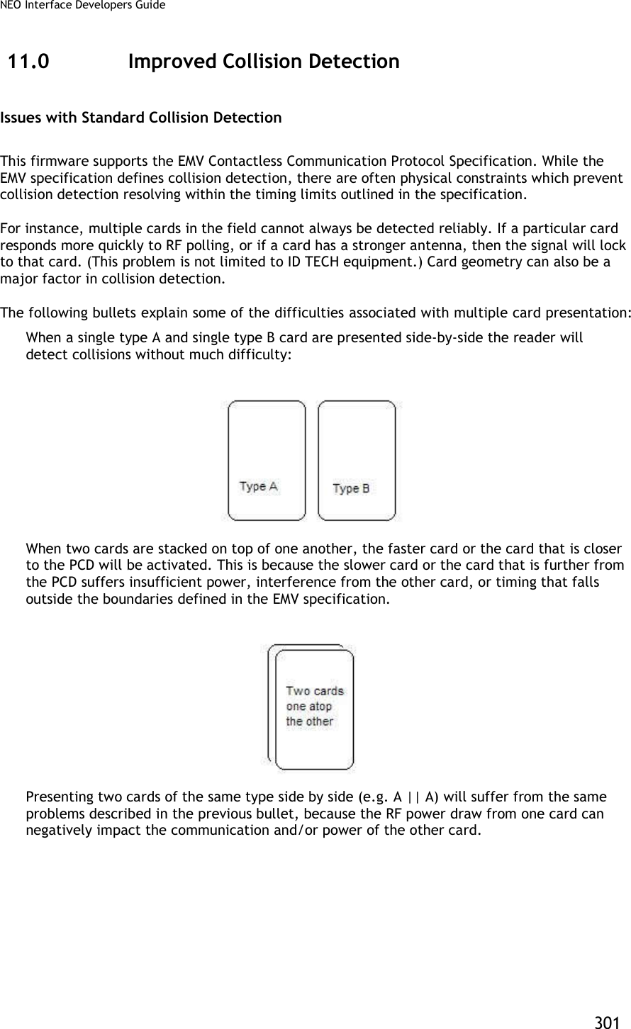
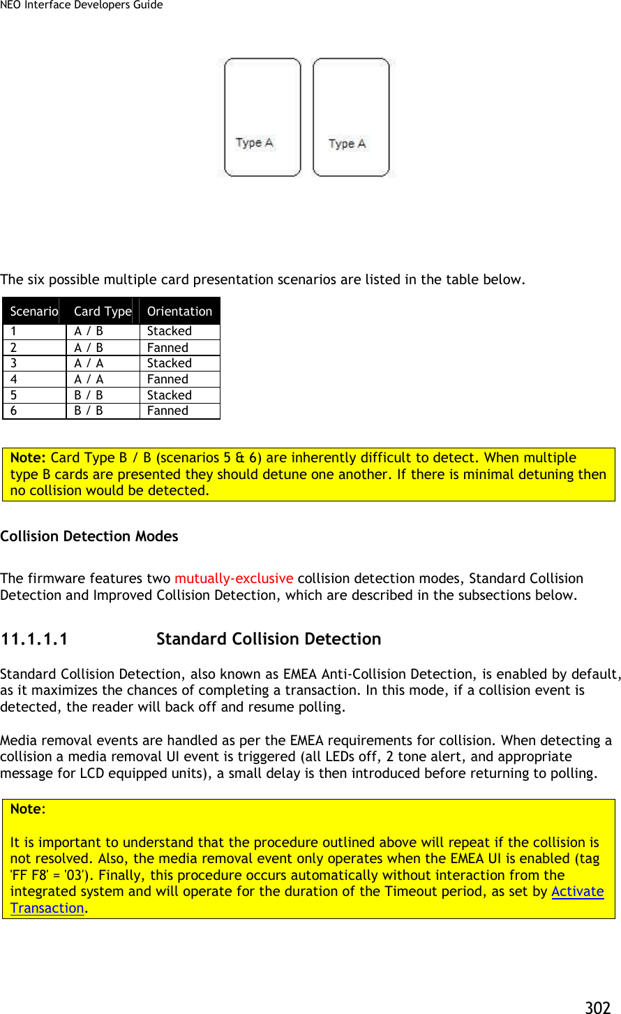
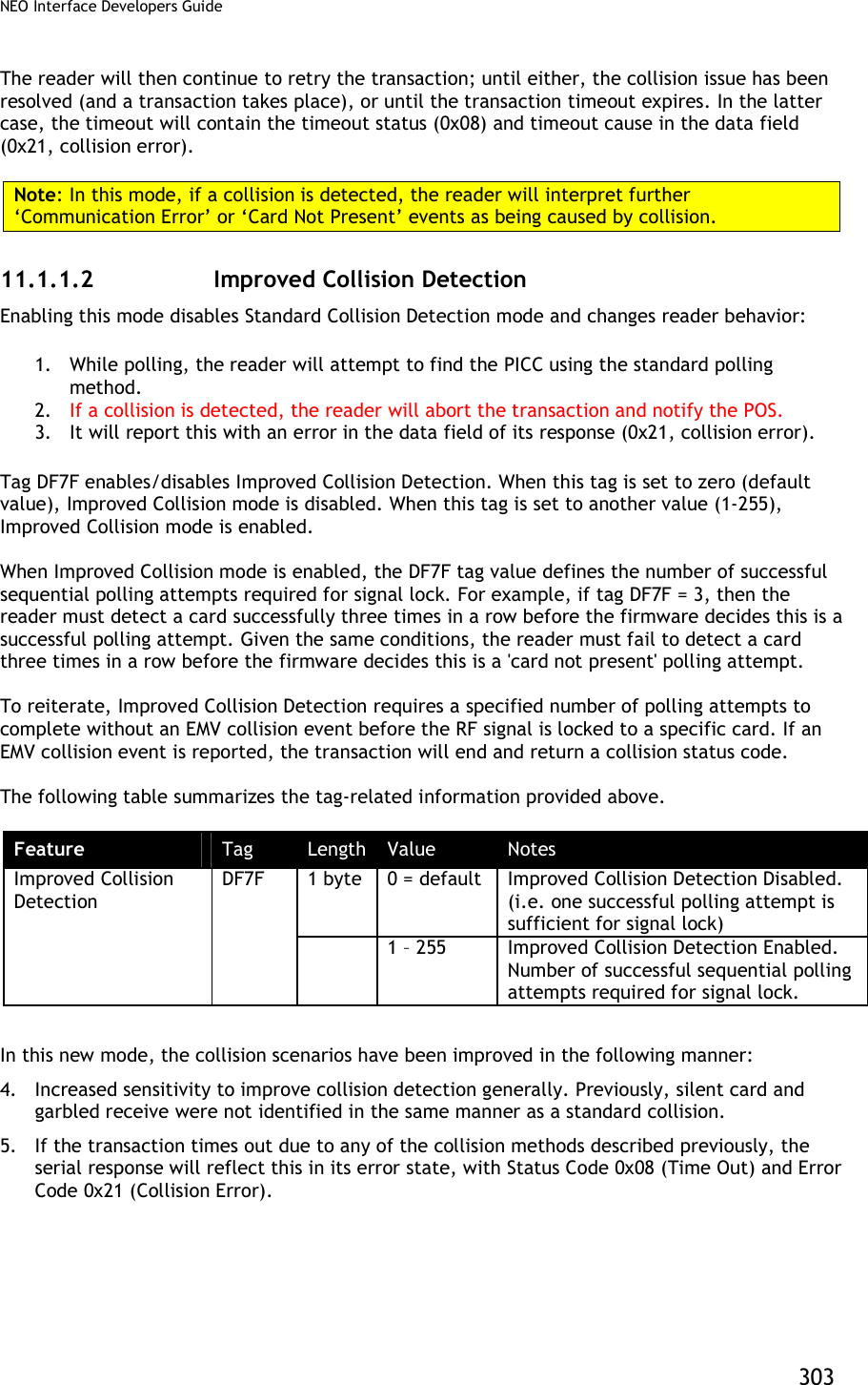
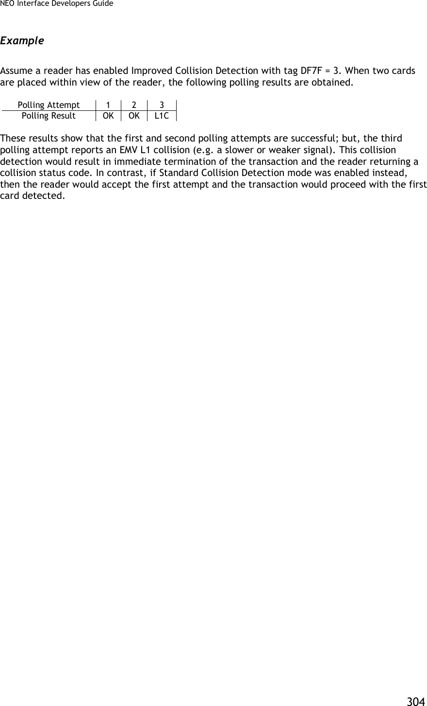
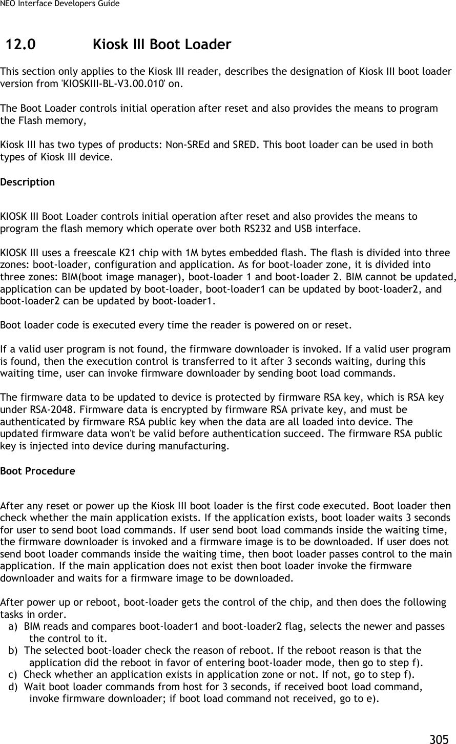
![NEO Interface Developers Guide 306 e) Transfer the control of the chip to application. f) wait for boot-loader commands from host. Communication Protocol All Firmware downloader commands are following Protocol 2. . Firmware Downloader File Name Format Firmware download file name is formatted as: '[firmware version]_[clear/encrypted]_[port].txt' [firmware version]: If the file is to update application, then [firmware version] is application main version. For example: 'NEO v1.00.012'. If the file is to update boot loader, then [firmware version] is boot loader version. for example: 'KIOSKIII-BL-V3.00.010'. If the file is to update both, then [firmware version] is showed as application main version and boot loader version linked with '&'. For example: ' NEO v1.00.012 & KIOSKIII-BL-V3.00.010' [clear/encrypted]: 'ENC' means this download file is encrypted 'CLR' means this download file is not encrypted If file name not marked with 'ENC' or 'CLR', that is encrypted file. If firmware key is valuable in device, please use encrypted download file. If firmware key is not valuable in device, please use clear download file. Note: Encrypted download files are generally used in firmware updating. Clear download files are only prepared for device recovery in special accidents. [port]: If the file is for RS232 port, then [port] is 'RS232'. If the file is for USBHID port, then [port] is 'USBHID'. ' NEO v1.00.016_CLR_RS232.txt' ' NEO v1.00.016_CLR_USBHID.txt' ' NEO v1.00.016_ENC_RS232.txt ' 'NEO v1.00.016_ENC_ USBHID.txt' ' KIOSKIII-BL-V3.00.014_CLR_RS232.txt' ' KIOSKIII-BL-V3.00.014_CLR_USBHID.txt' ' KIOSKIII-BL-V3.00.014_ENC_RS232.txt' 'KIOSKIII-BL-V3.00.014_ENC_ USBHID.txt' ' NEO v1.00.016 & KIOSKIII-BL-V3.00.014_CLR_RS232.txt' ' NEO v1.00.016 & KIOSKIII-BL-V3.00.014_CLR_USBHID.txt' ' NEO v1.00.016 & KIOSKIII-BL-V3.00.014_ENC_RS232.txt' ' NEO v1.00.016 & KIOSKIII-BL-V3.00.014_ENC_USBHID.txt'](https://usermanual.wiki/ID-TECH/VP3600/User-Guide-3704675-Page-318.png)
![NEO Interface Developers Guide 307 Firmware Downloader Data Format Firmware download file is coded in ASCII text. Firmware download commands and expected responses are embed in text file one command per line. Host can retrieve each command in order and convert the command from ASCII code to hex data then send them to Kiosk III device, then compare the response from Kiosk III device with expected response next to the command in text file. Firmware download file data format is as: '[prefix][data]' Prefix Data Example Description '#' 'XXXXX...' Data follow '#' is comments only. '<START:' None No data needed, just specify the starting of download. 'TIMEOUT:' '1000' Recommended timeout between command and response, unit is ms. 'SLEEP:' '2000' Host sleep, unit is ms. 'SEND:' ' 5669564F746563683200C7110000F23D' Data is the command to be sent to device. Note: Data format is different between RS232 port and USBHID port. 'WAIT:' ' 5669564F746563683200C7000000866E' Data is the response expected to the command above line. Note: Data format is different between RS232 port and USBHID port. 'END>' None No data needed, just specify the ending of download. Examples: NEO v1.00.012_RS232.txt #RS232 version <START: TIMEOUT:1000 SEND:5669564F746563683200C7410000ACF3 SLEEP:2000 SEND:5669564F746563683200C7110000F23D WAIT:5669564F746563683200C7000000866E SEND:5669564F746563683200C7120001014A91 WAIT:5669564F746563683200C7000000866E SEND: 5669564F746563683200C71301008A8D92719D9D....... WAIT:5669564F746563683200C7000000866E ...... ...... ...... WAIT:5669564F746563683200C7000000866E SEND:5669564F746563683200C71500083230313530393234BE8B WAIT:5669564F746563683200C7000000866E SEND:5669564F746563683200C716000077AD WAIT:5669564F746563683200C7000000866E END> NEO v1.00.012_USBHID.txt #USBHID version <START:](https://usermanual.wiki/ID-TECH/VP3600/User-Guide-3704675-Page-319.png)
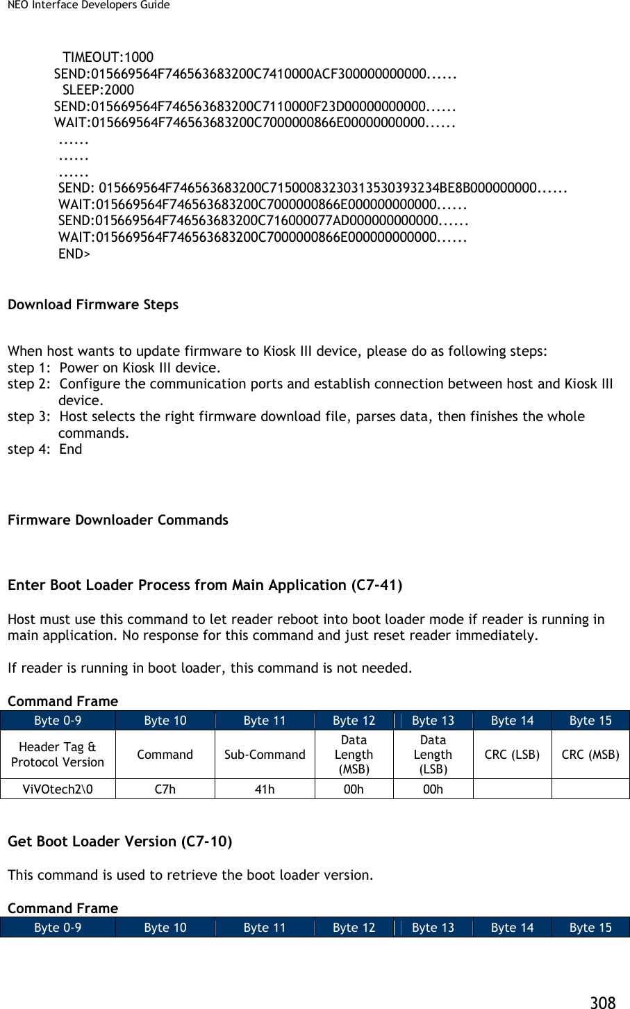
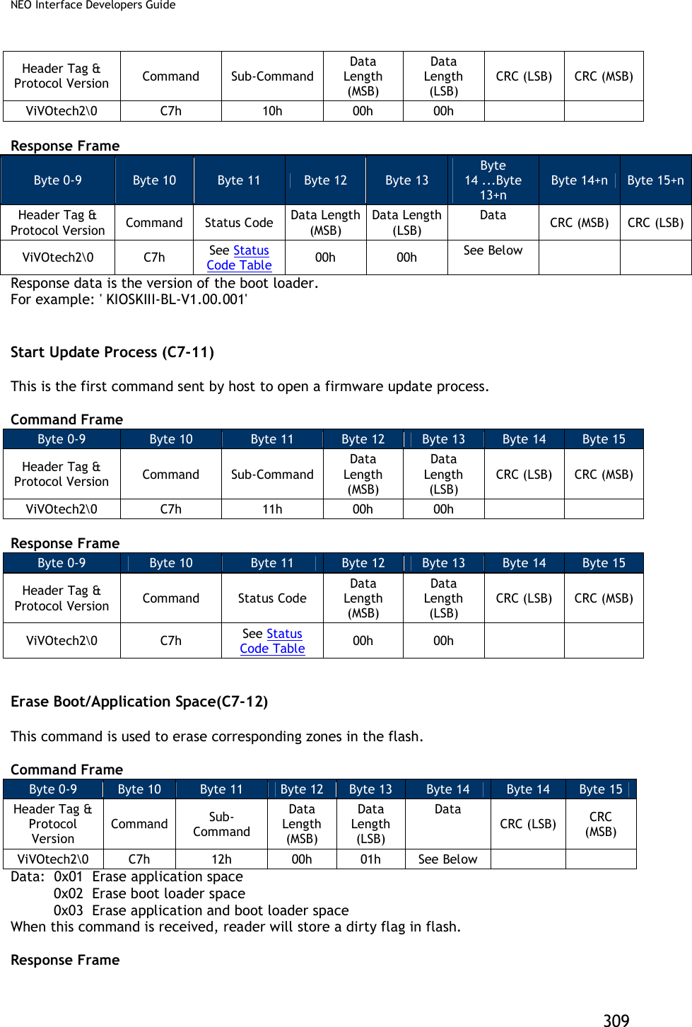
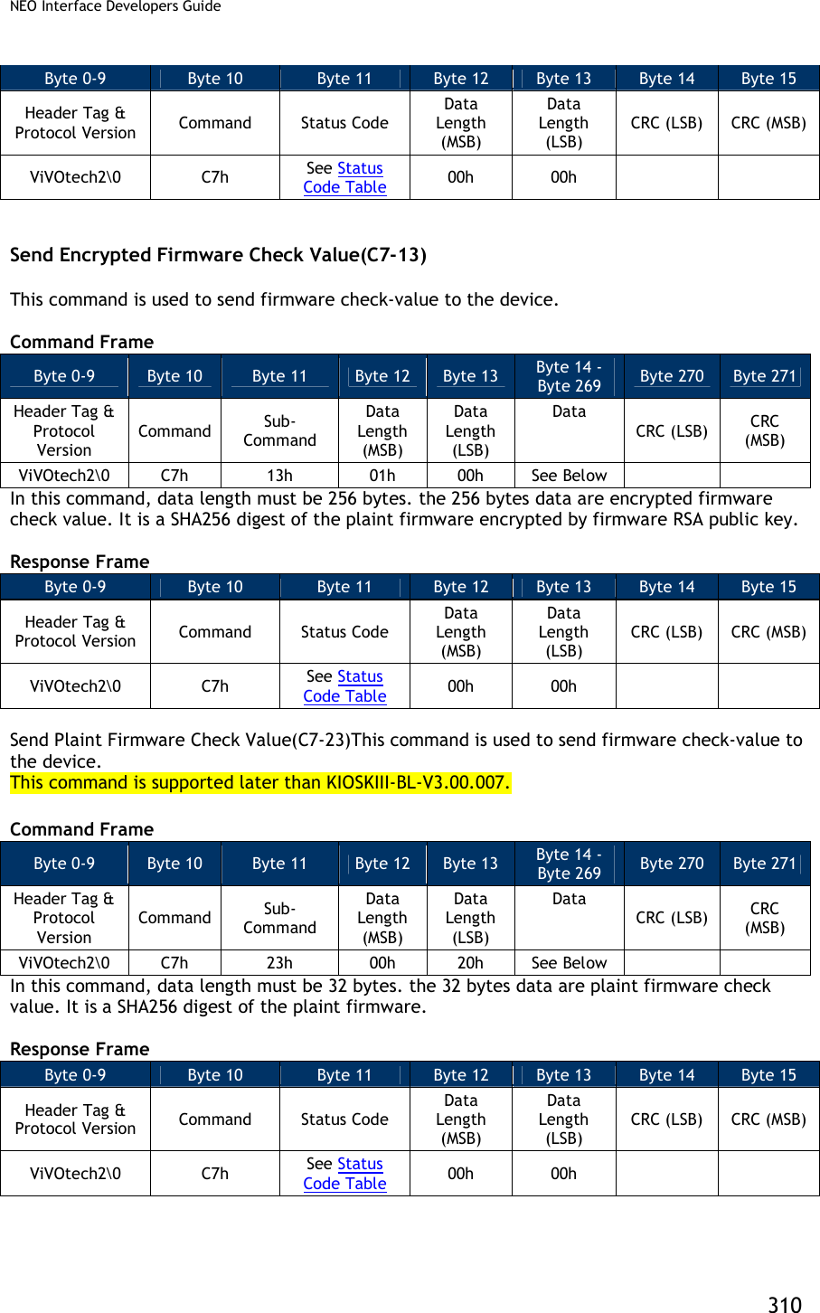
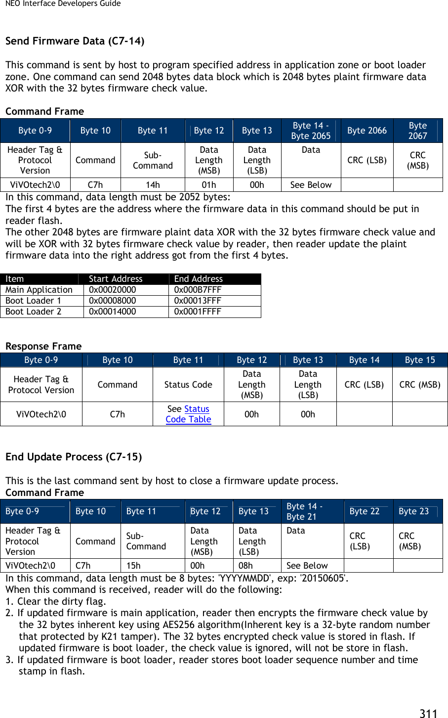
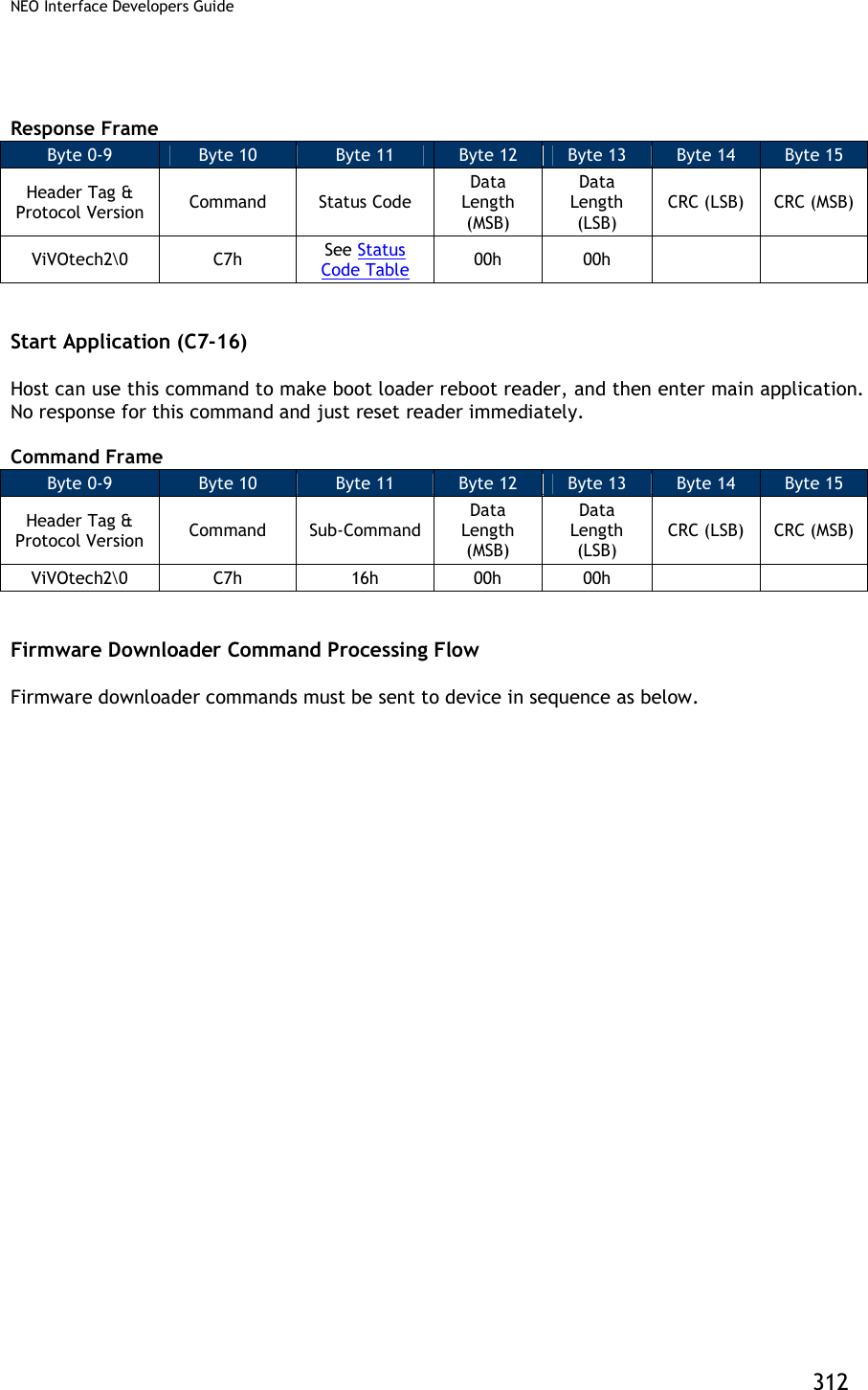
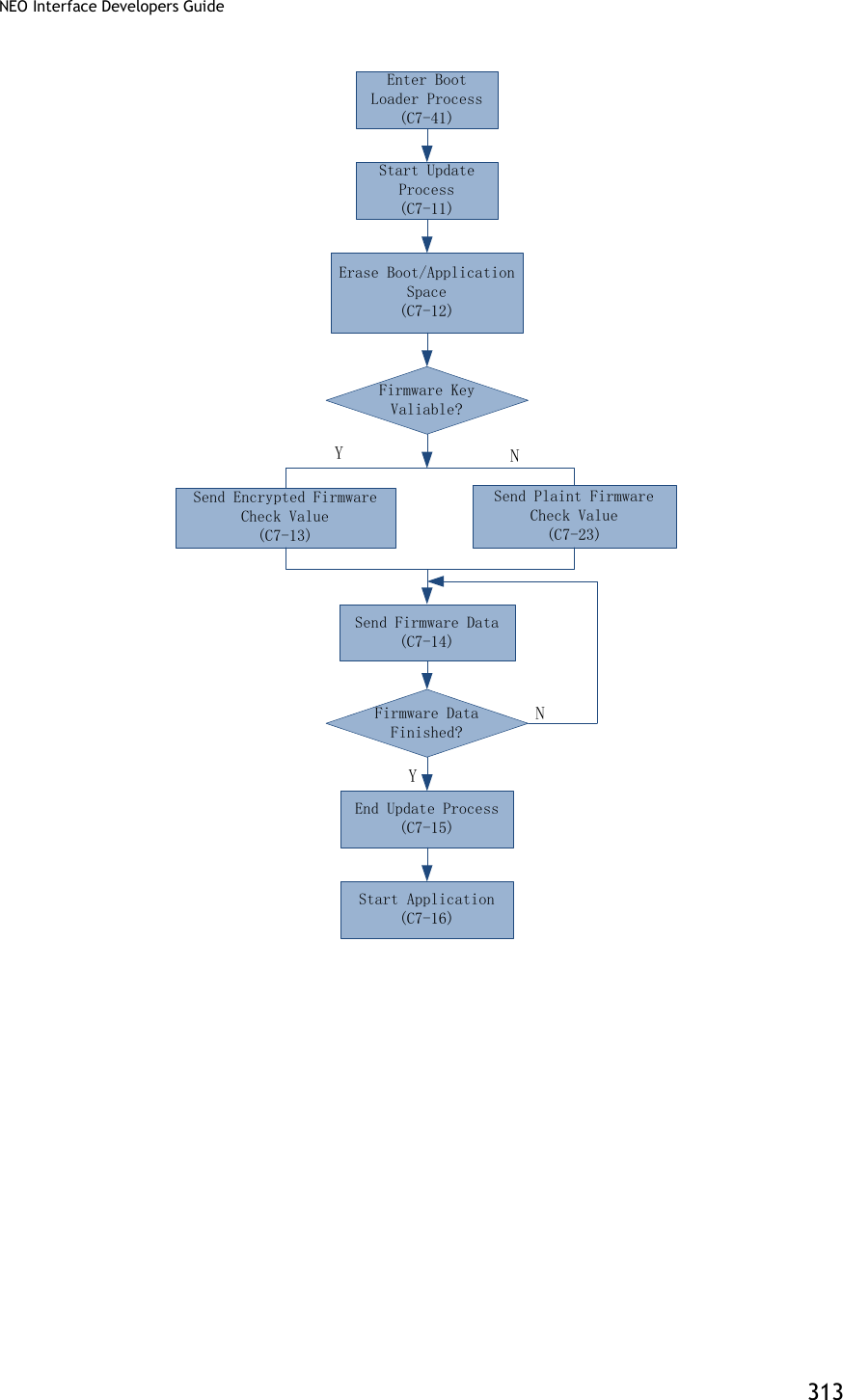
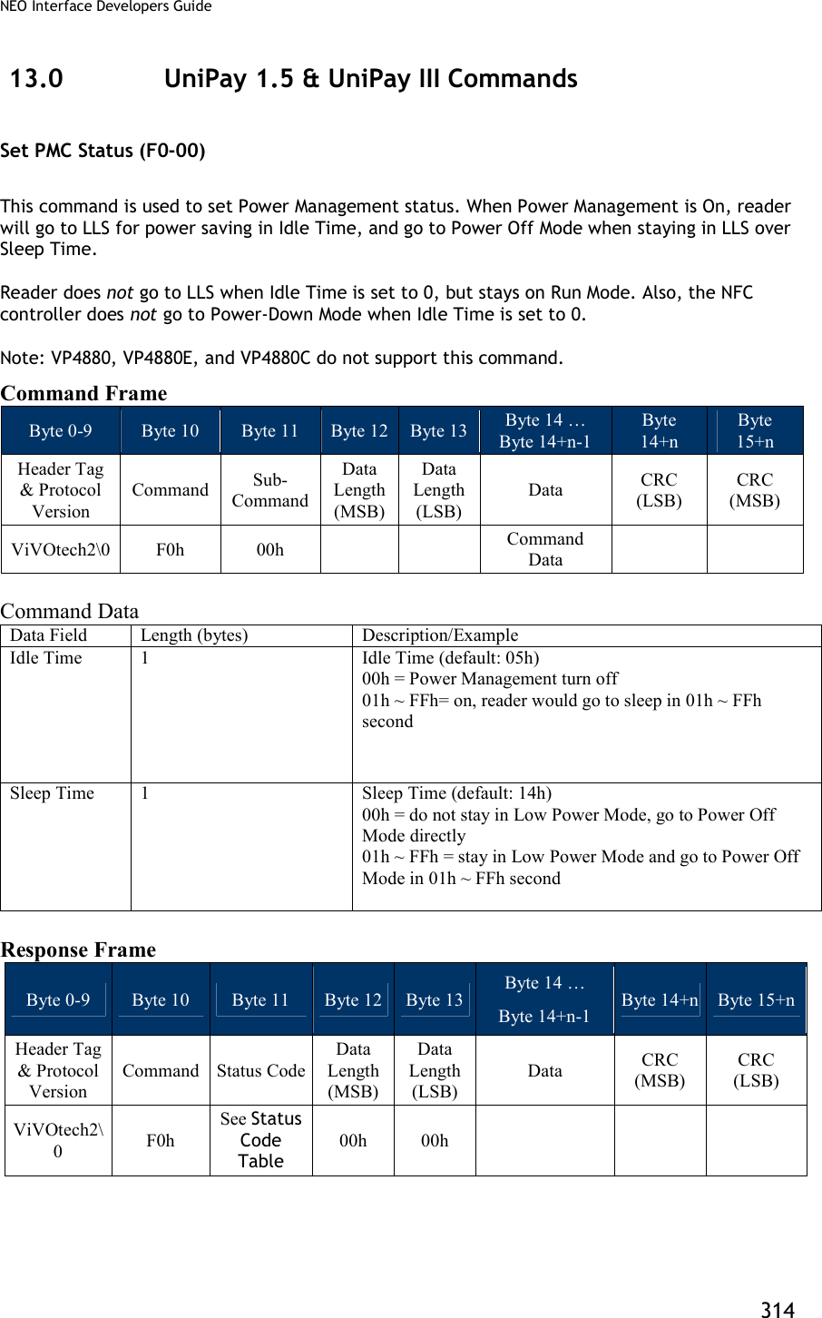
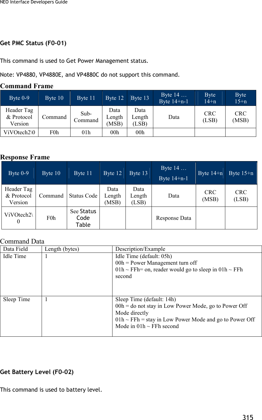
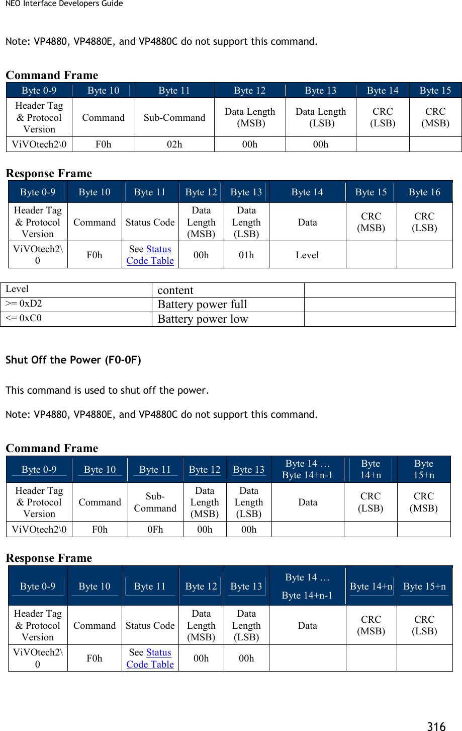

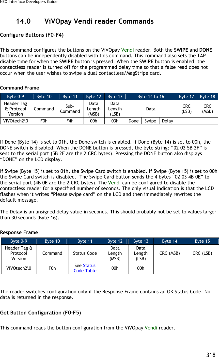
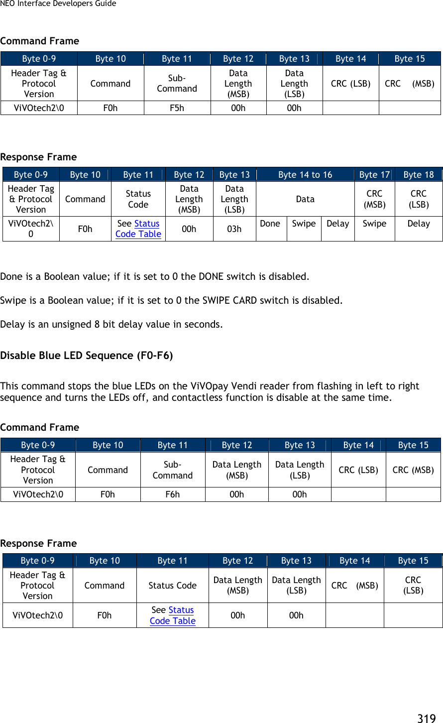
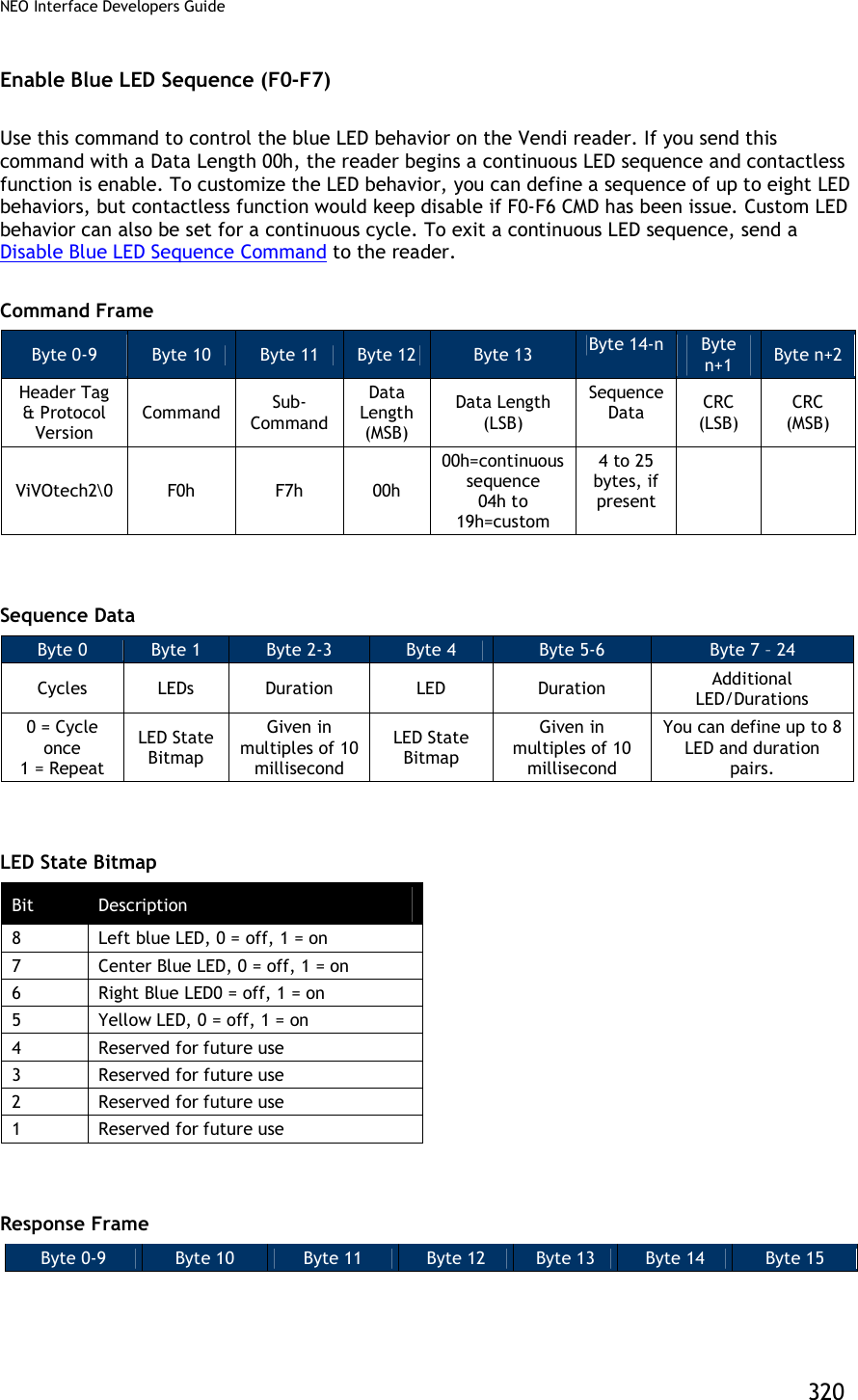
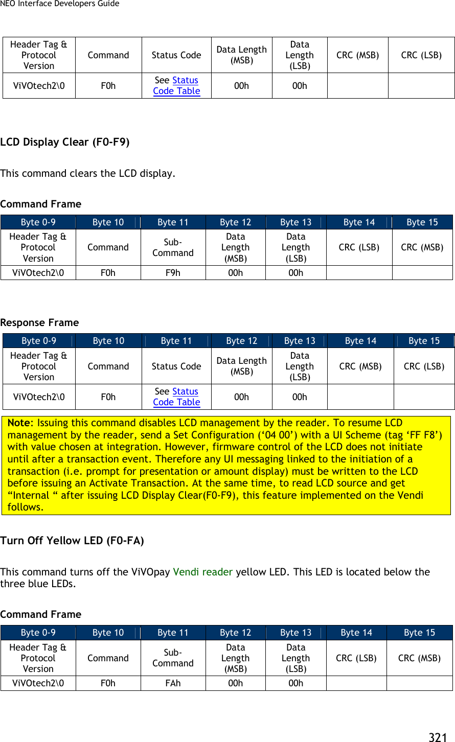
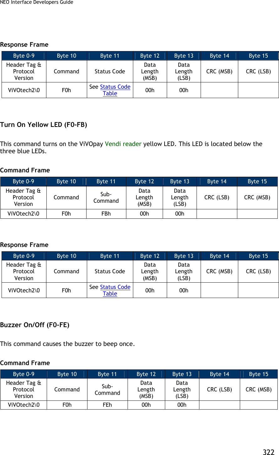
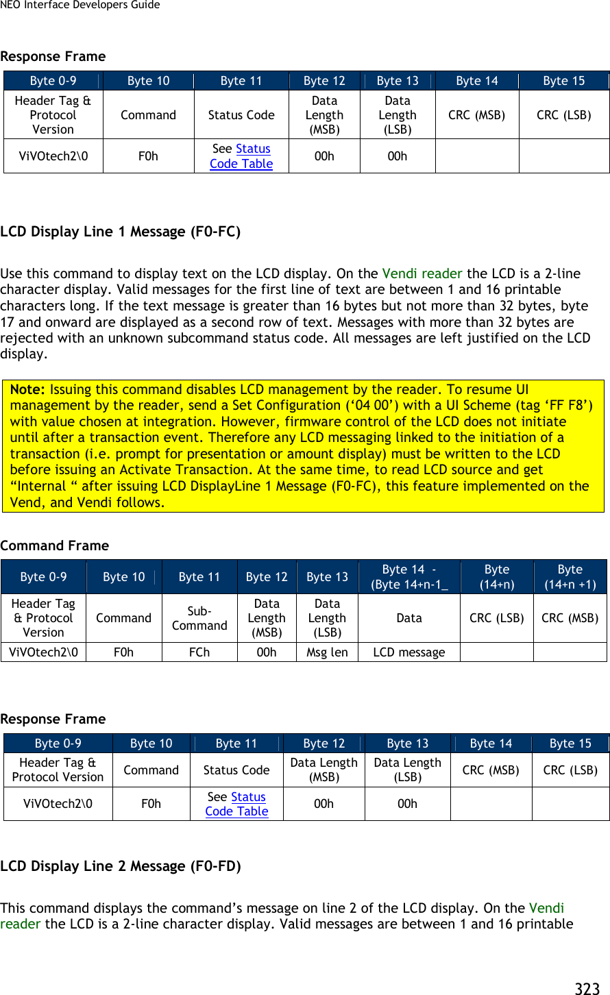
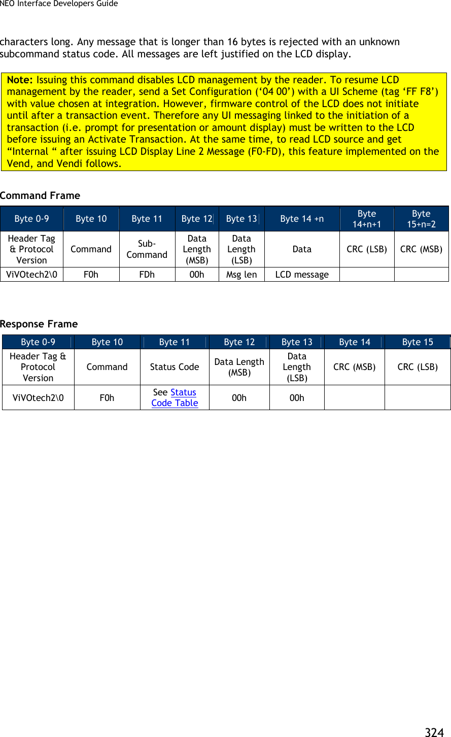
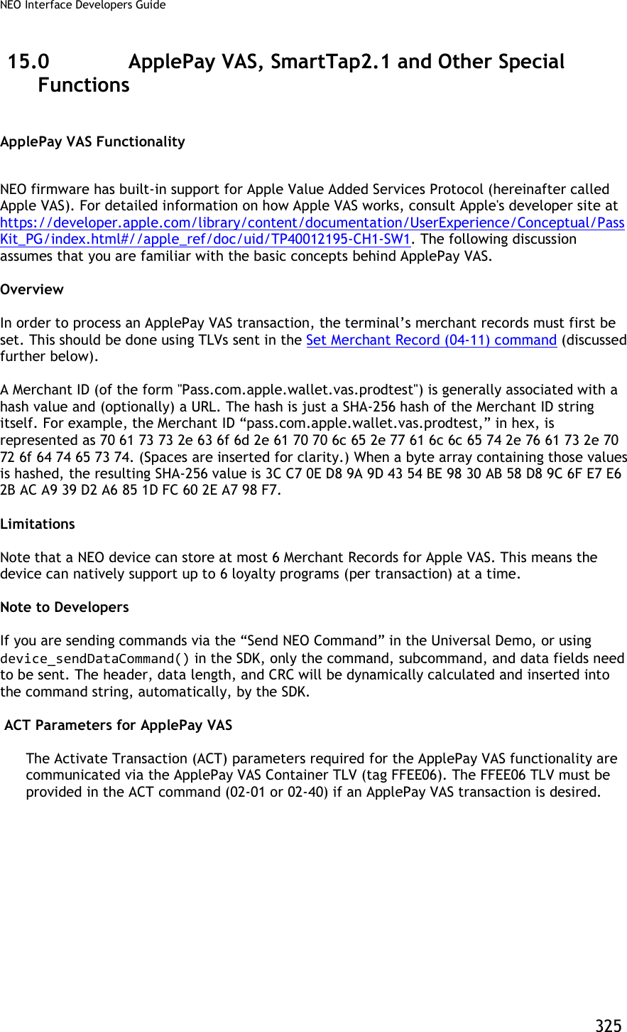
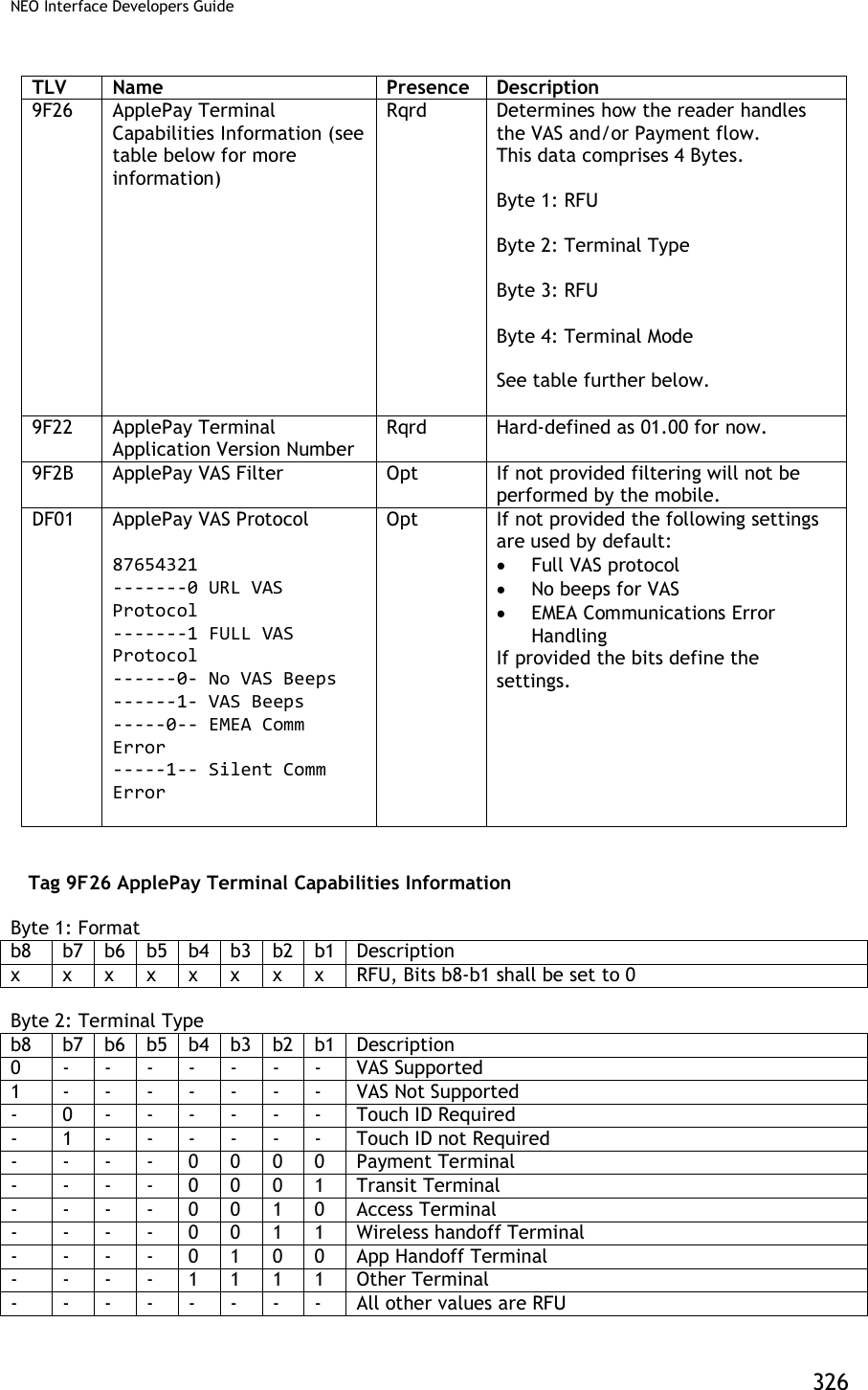
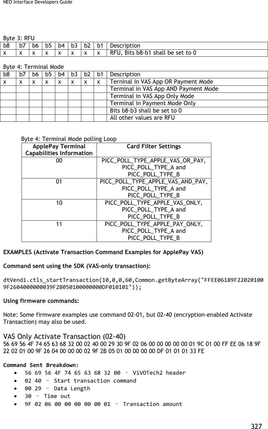
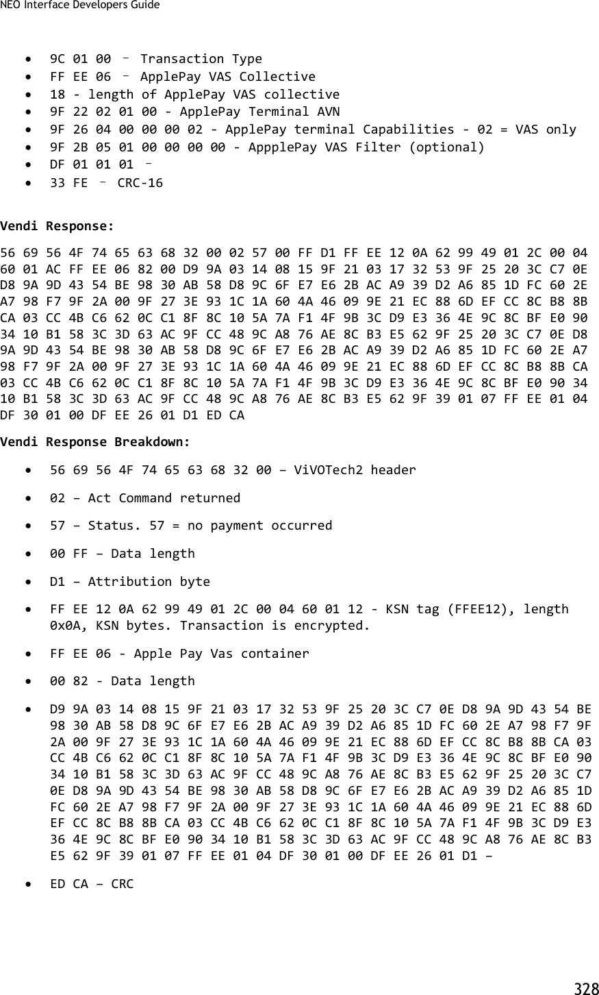
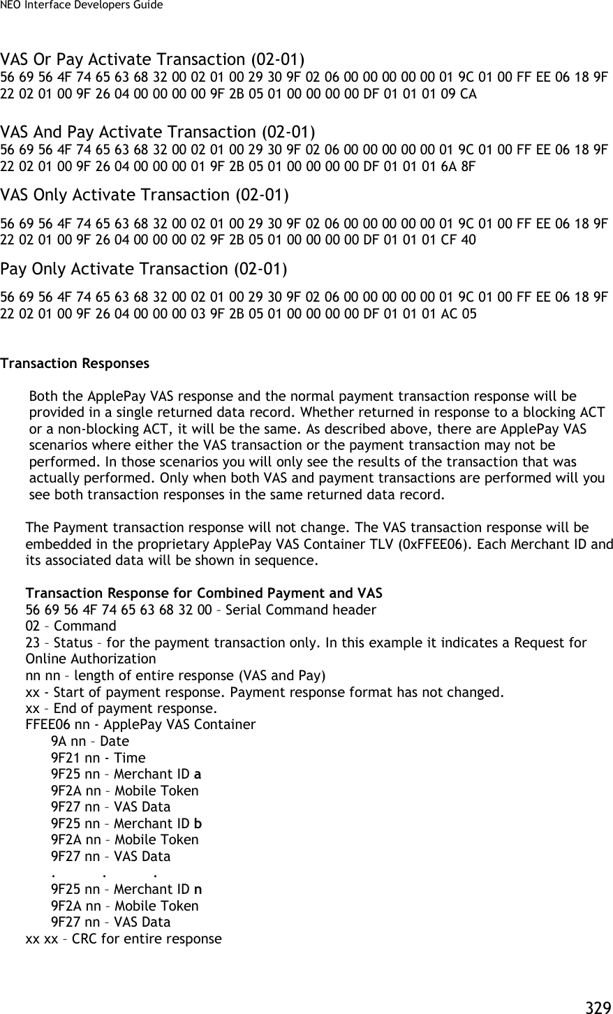
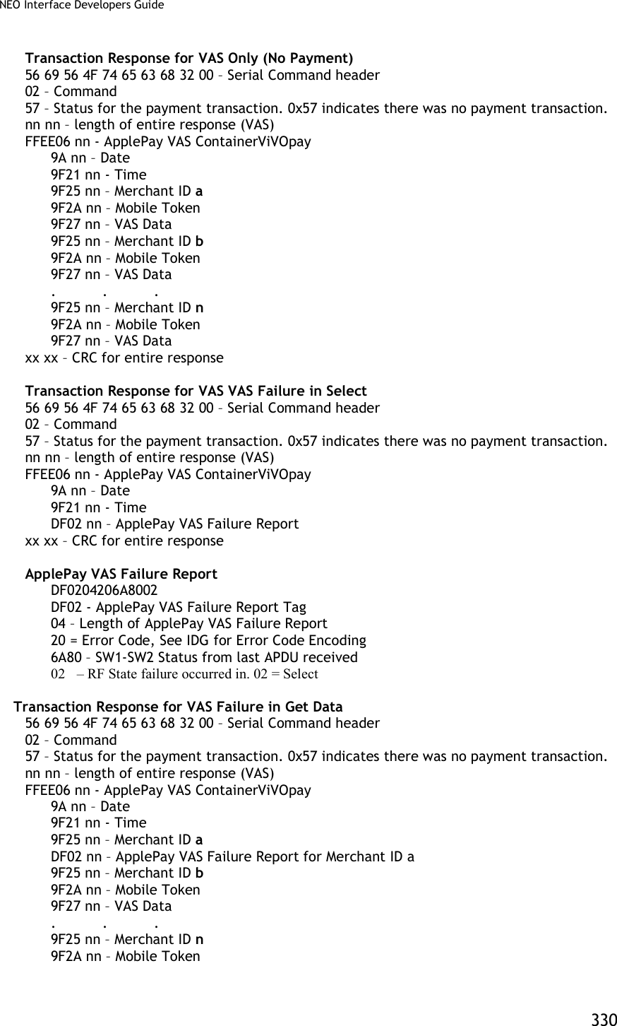
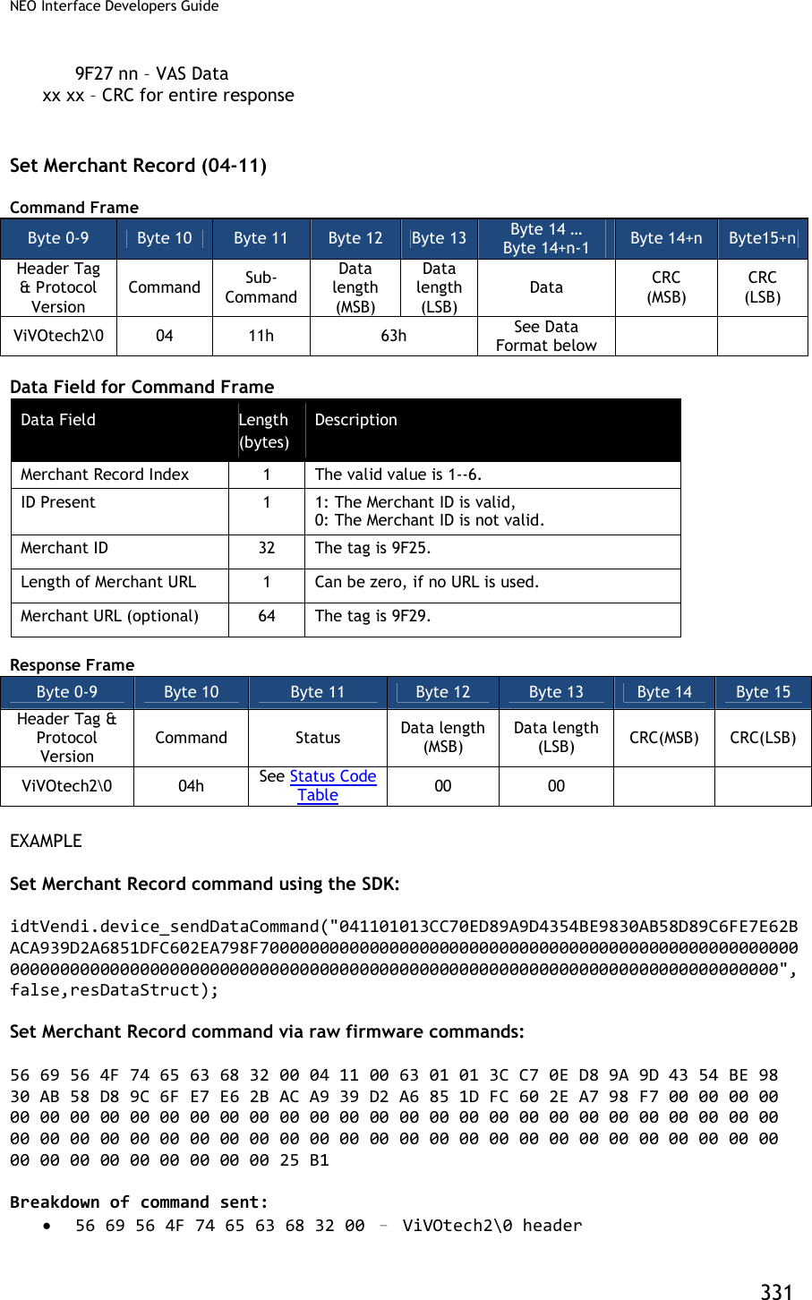
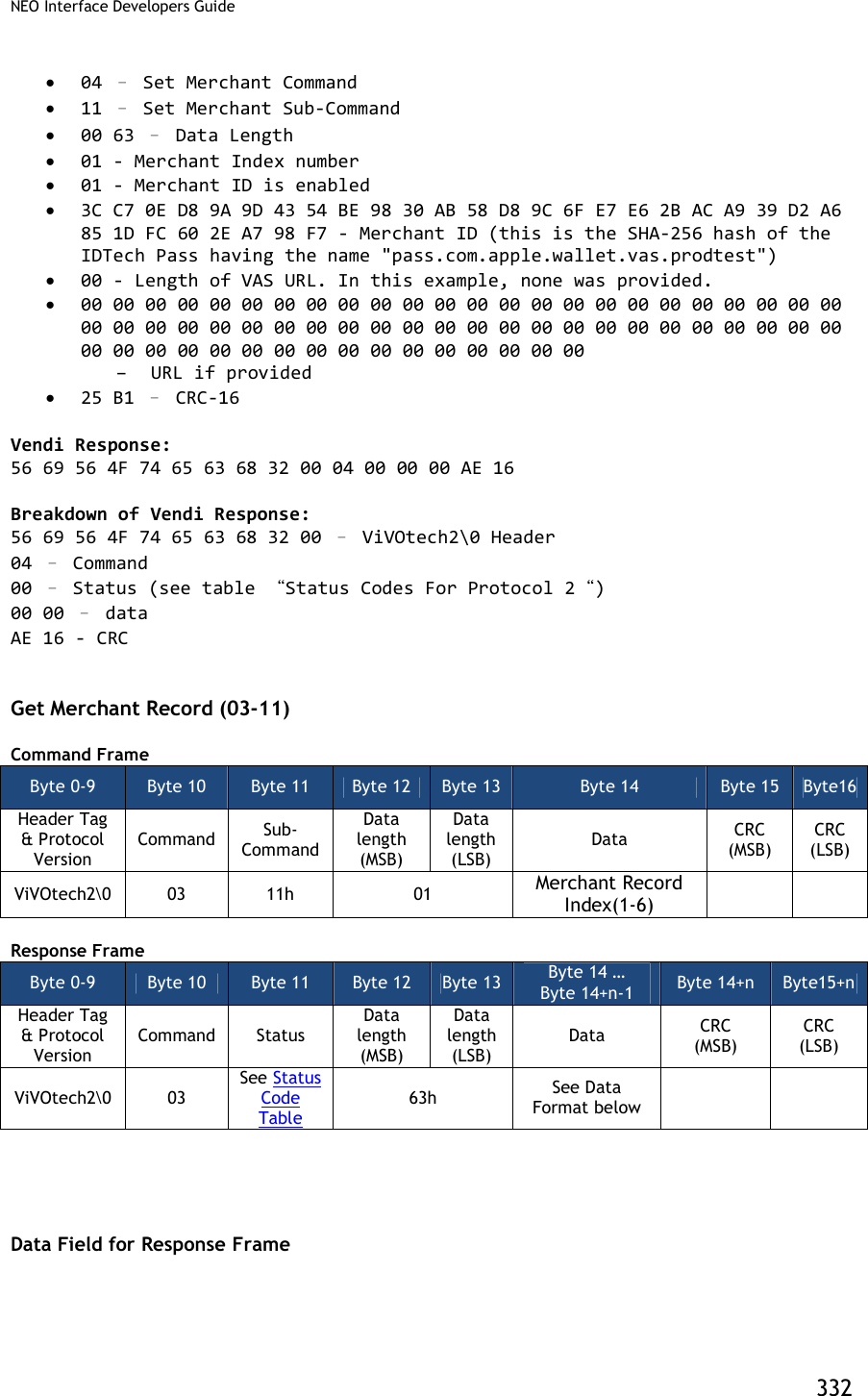
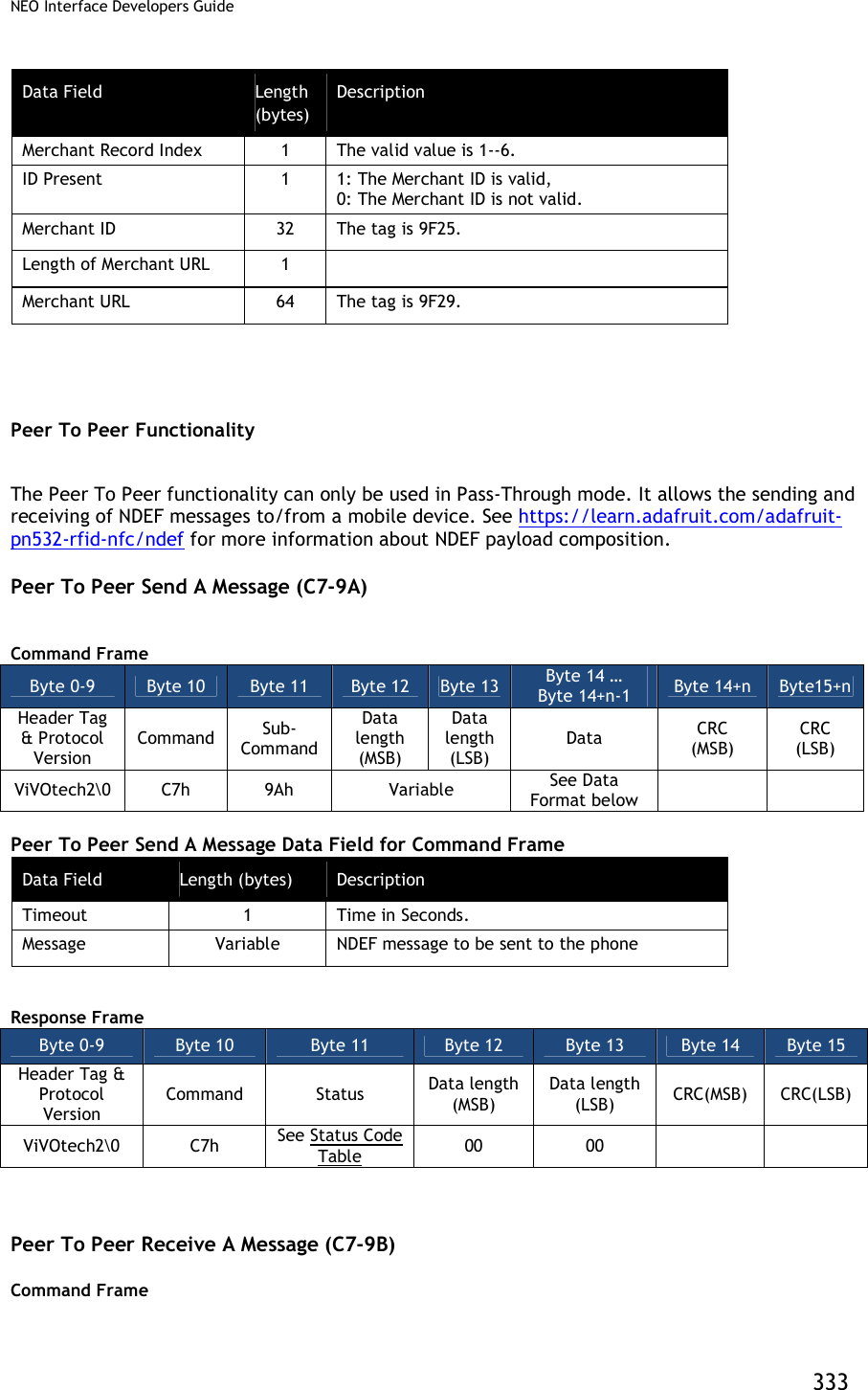
![NEO Interface Developers Guide 334 Byte 0-9 Byte 10 Byte 11 Byte 12 Byte 13 Byte 14 Byte 15 Byte16 Header Tag & Protocol Version Command Sub- Command Data length (MSB) Data length (LSB) Data CRC (MSB) CRC (LSB) ViVOtech2\0 C7 9Bh 00h 01h Timeout (1 byte, time in seconds) Response Frame Byte 0-9 Byte 10 Byte 11 Byte 12 Byte 13 Byte 14 … Byte 14+n-1 Byte 14+n Byte 15+n Header Tag & Protocol Version Command Status Data length (MSB) Data length (LSB) Data CRC (MSB) CRC (LSB) ViVOtech2\0 C7h See Status Code Table Variable See Data description below If Status code is OK, Data Field for Response Frame is a message received from the phone. Otherwise, Data Length is zero and no data for Response Frame. Messages conform to NDEF (https://learn.adafruit.com/adafruit-pn532-rfid-nfc/ndef). Asynchronous Media Tracking (Only for Kiosk III) This feature is to generate notifiation events to indicate that a card has arrived in or departed form the RF field. Reader has the ability to send out Asynchronous Packet of card arrival or card removal to the POS in real-time. The Asynchronous Packet for Meida Tracking is : 07 50 [Payload] [CRC] 07 - Async MTAS Packet 50 - Status OK [Payload] - Tag DFEF36 (3 byte Tag ID, 1 byte length, 4 data bytes) [CRC] - 2 byte CRC This feature can be enabled by setting the bits appropriately in the first byte of MTAS. It is done via the Set Configuration Command (04-00), This is the only way to set this tag. If CL media arrival reporting is enabled, reader will send out a Asynchronous Packet to the POS to tell card arriving. This feature is supported in both Native mode and Pass Through mode. For example: 07 50 DF EF 36 04 03 0B 00 00 CC 8F If CL media removal reporting is enabled, reader will send out a Asynchronous Packet to the POS to tell card removal. This feature is only supported in Native mode. For example: 07 50 DF EF 36 04 03 11 00 00 48 2D Send Media Status Tracking Asynchronously in Pass Through Mode Card removal reporting is not supported in Pass Through mode, If CL media arrival reporting bit is set, reader will send out a Asynchronous Packet when reader detects a card during Poll for Token command (standard or enhanced).](https://usermanual.wiki/ID-TECH/VP3600/User-Guide-3704675-Page-346.png)
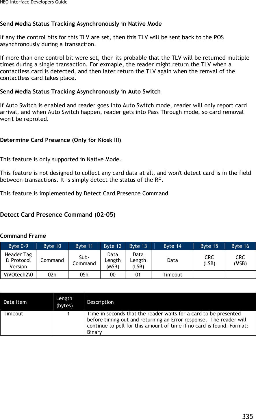
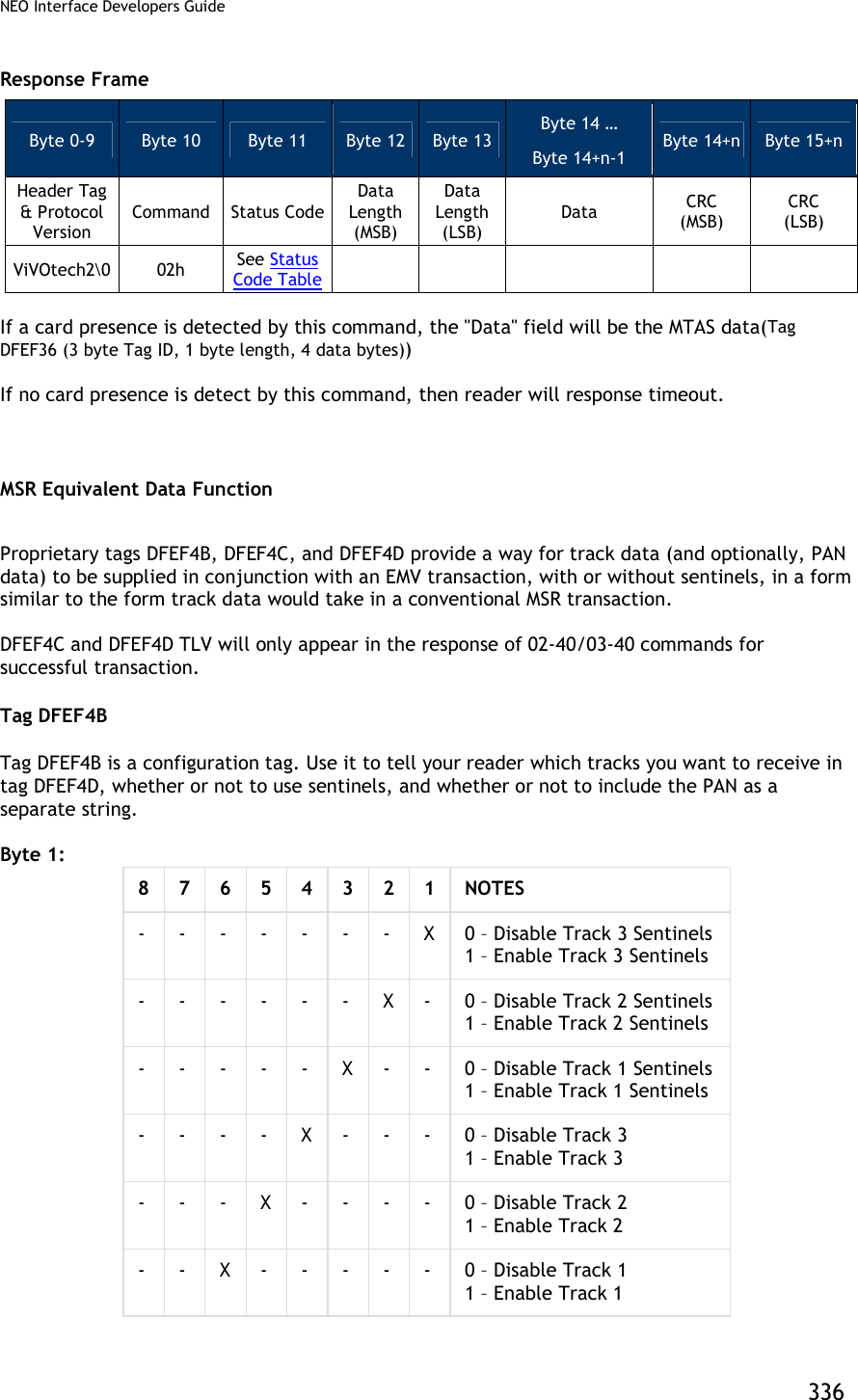
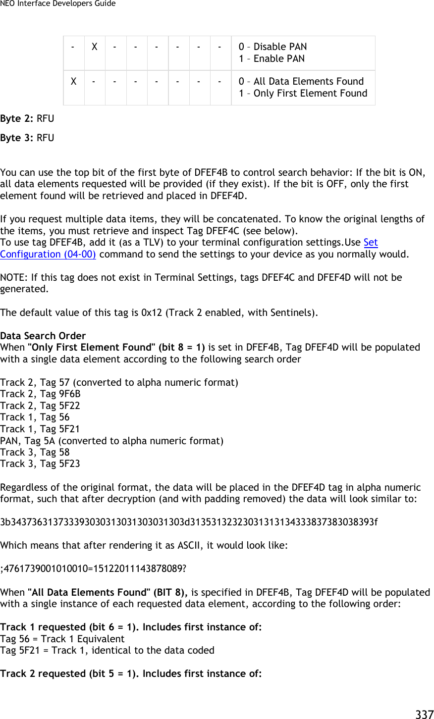
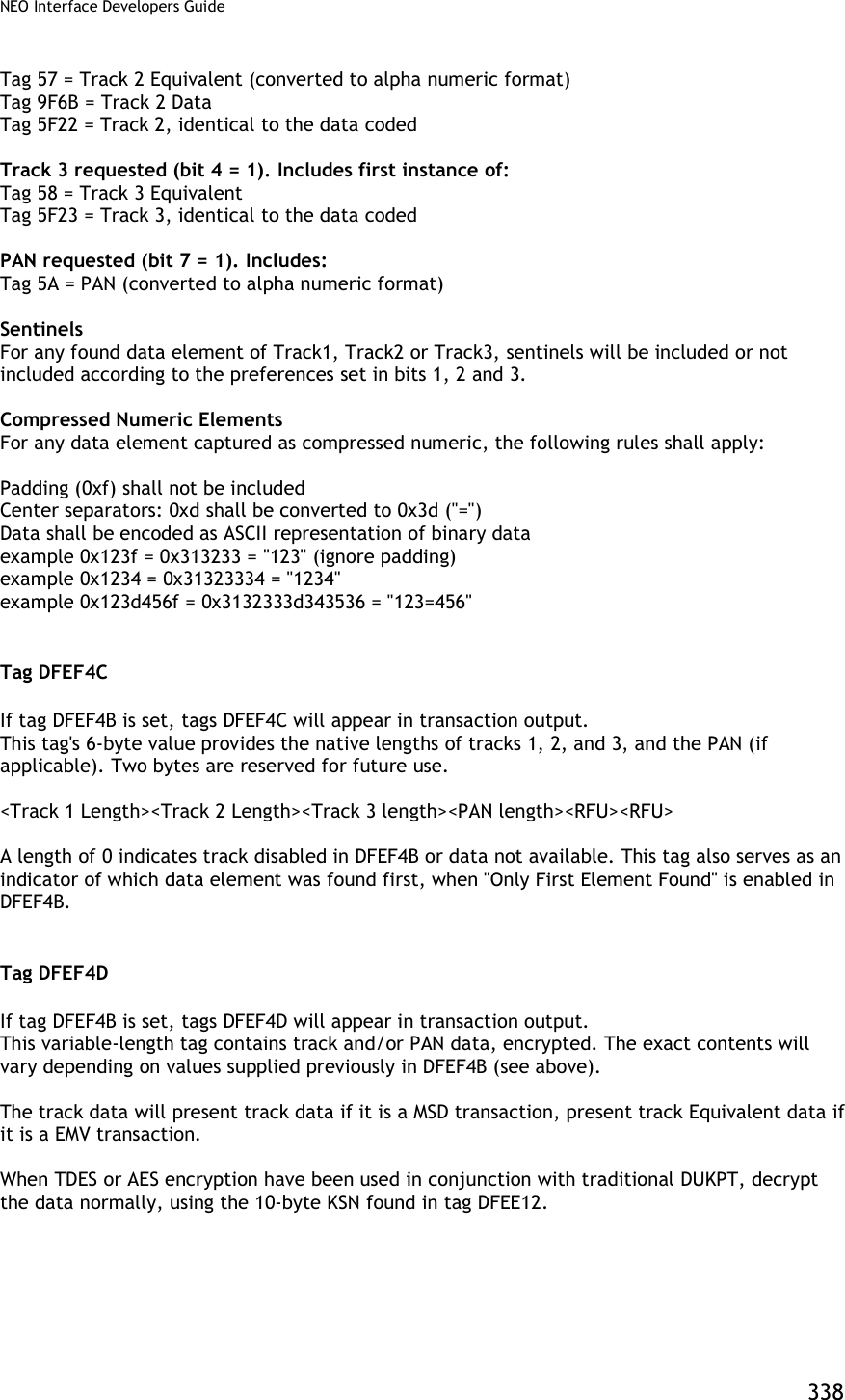
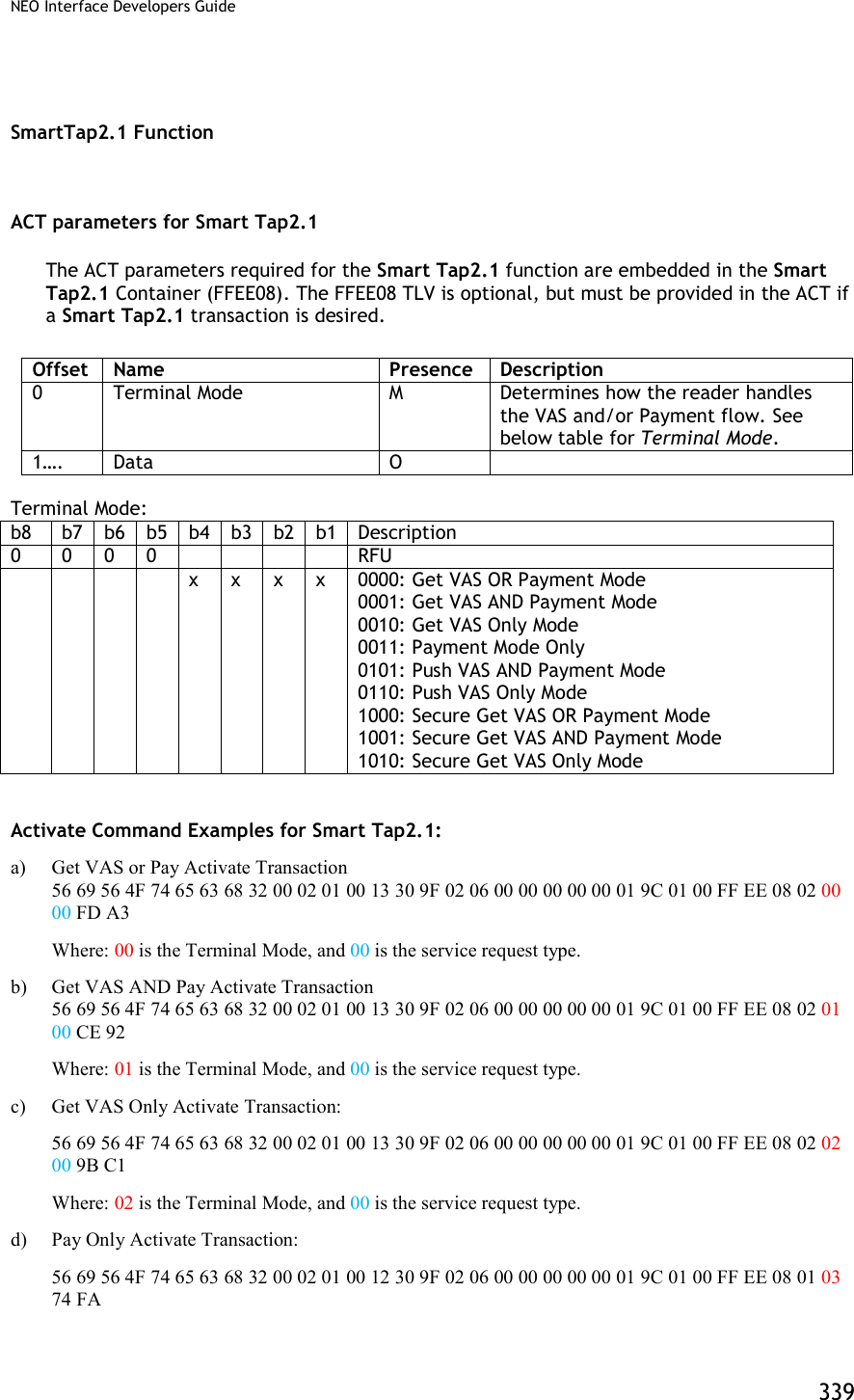
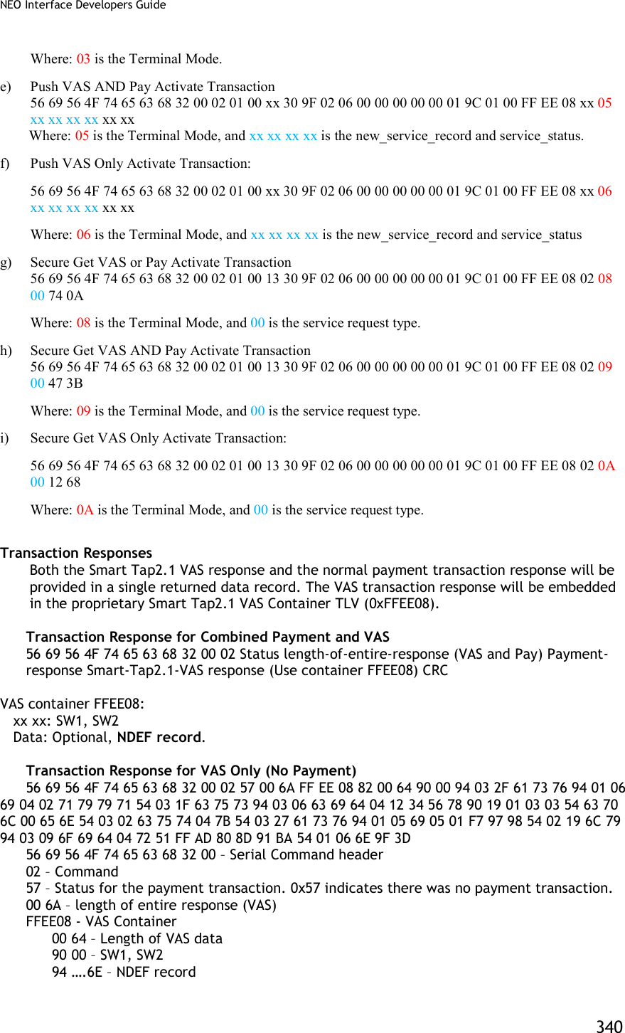
![NEO Interface Developers Guide 341 9F 3D – CRC for entire response SmartTap configuration There are several configurations for device. Below is the list together with the corresponding tags. a) Merchant ID: 9F16 b) Store location ID: DFEF66 c) Terminal ID: 9F1C d) Merchant Name: 9F4E e) Merchant Category: 9F15 f) POS Capabilities Bitmaps: DFEF67 This value defines the capabilities of the terminal g) Retry Times: DFEF68 This value defines the retry times if errors occurred. h) Select OSE support: DFEF69 0x01 means support Select OSE APDU, while 0x00 means NOT. i) Skip Second Select support: DFEF6A 0x01 means skip second select, while 0x00 means NOT. j) Stop Payment if smart tap2.1 failed support: DFEF6B k) Pre-Signed support: DFEF6C Command: Use command 04-03 to set SmartTap2.1 configuration. The command should include the group number (DF EE 2D) as the first TLV data, and Smart Tap2.1 AID (9F06) as the second TLV. Below is an example to set Smart Tap configuration to group 2: 56 69 56 4F 74 65 63 68 32 00 04 03 00 23 DF EE 2D 01 02 9F 06 07 A0 00 00 04 76 D0 00 9F 16 04 00 BC 61 4E DF EF 66 00 9F 1C 00 9F 4E 00 9F 15 00 xx xx Long term private key update To maintain SmartTap2.1 function, a long term private key should be stored in the device. Kelso use method 2 to update long term private key: [SmartTap2.1-Part1-NFCProtocol-v0.975.pdf, page 47] The terminal vendor encrypts the private key using a key encryption key. The encrypted private key is provided to the merchant. The merchant configures the VAS command with the encrypted private key as a parameter. The terminal uses the corresponding key decryption key already in the terminal to decrypt the encrypted private key. The input long term key (37 bytes) format: Version: 4 bytes Compressed Key: 33 bytes (A zero followed by long term private key) Command: Use command C7-62 to set long term key The key parameter (Version + Compressed Key) is encrypted using ID TECH’s private RSA-2048-Key. To set the long term private key: 56 69 56 4F 74 65 63 68 32 00 C7 62 01 20 encrypted-data (256 bytes) plain-data-hash (32 bytes) xx xx Note: According to Google, a new command is added to update plaintext long term private key.](https://usermanual.wiki/ID-TECH/VP3600/User-Guide-3704675-Page-353.png)
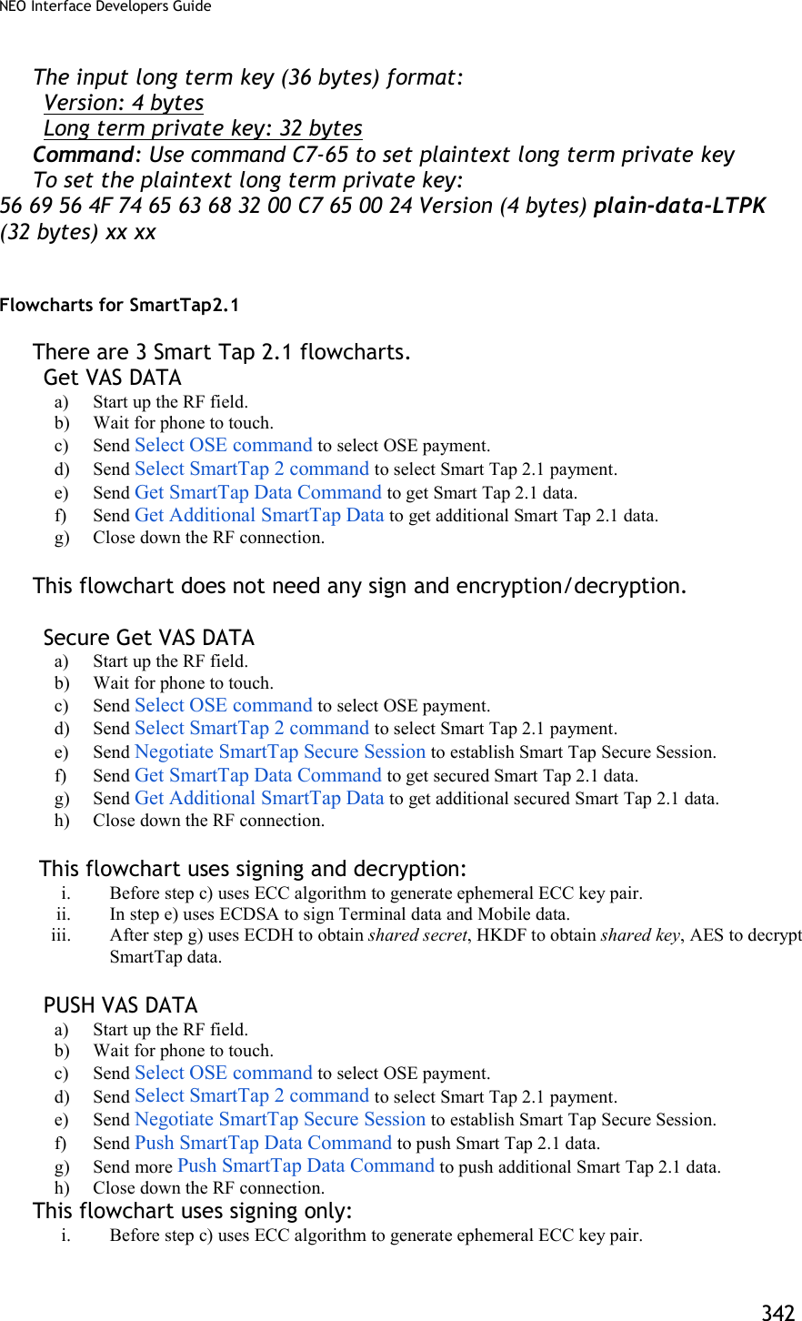
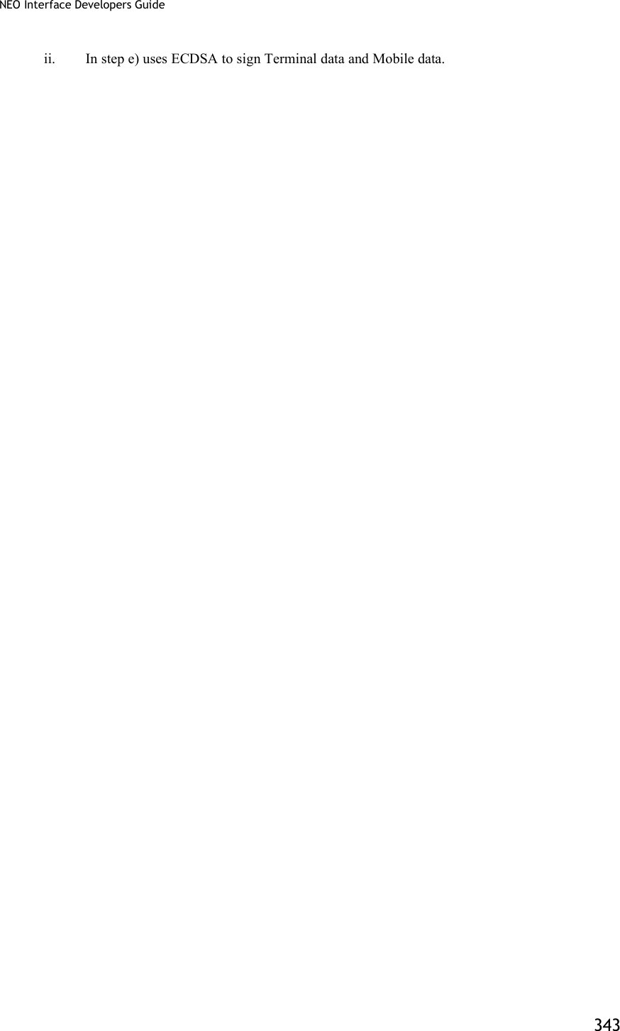
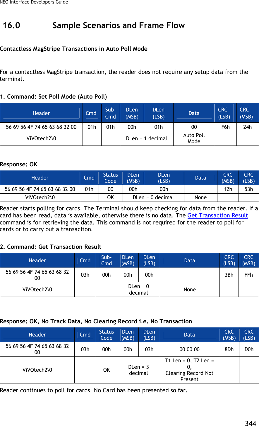
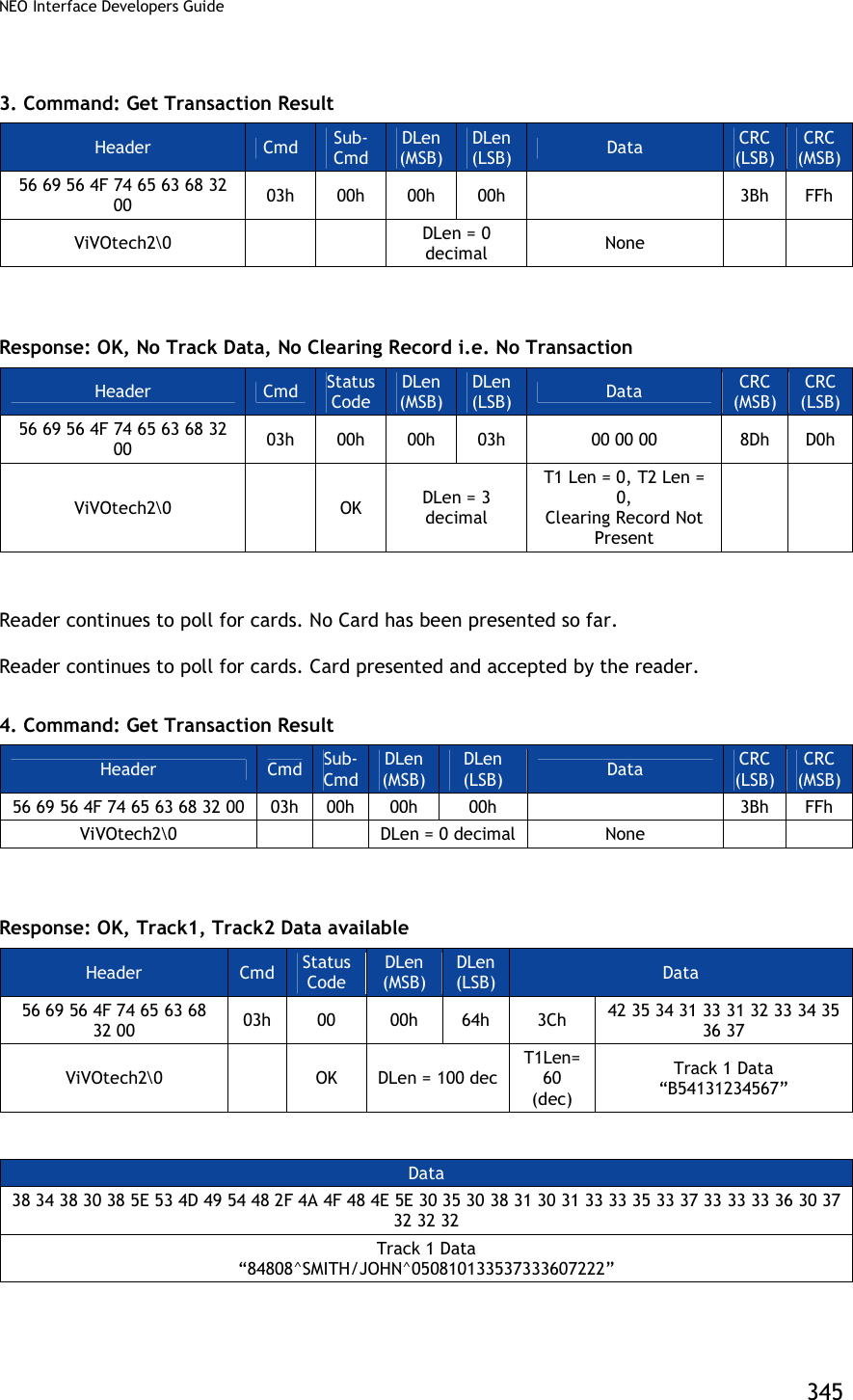
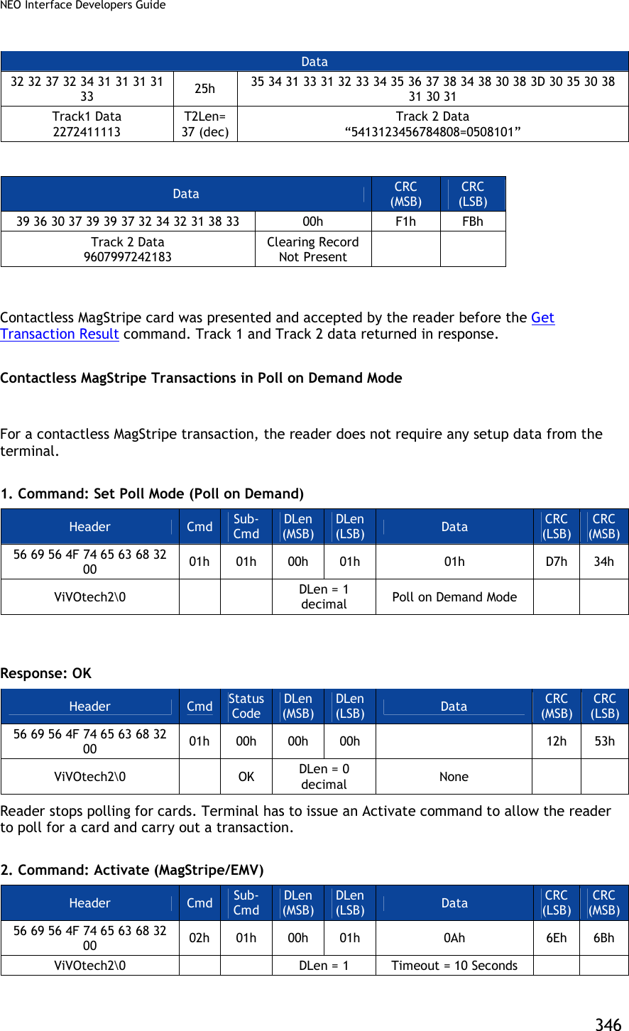
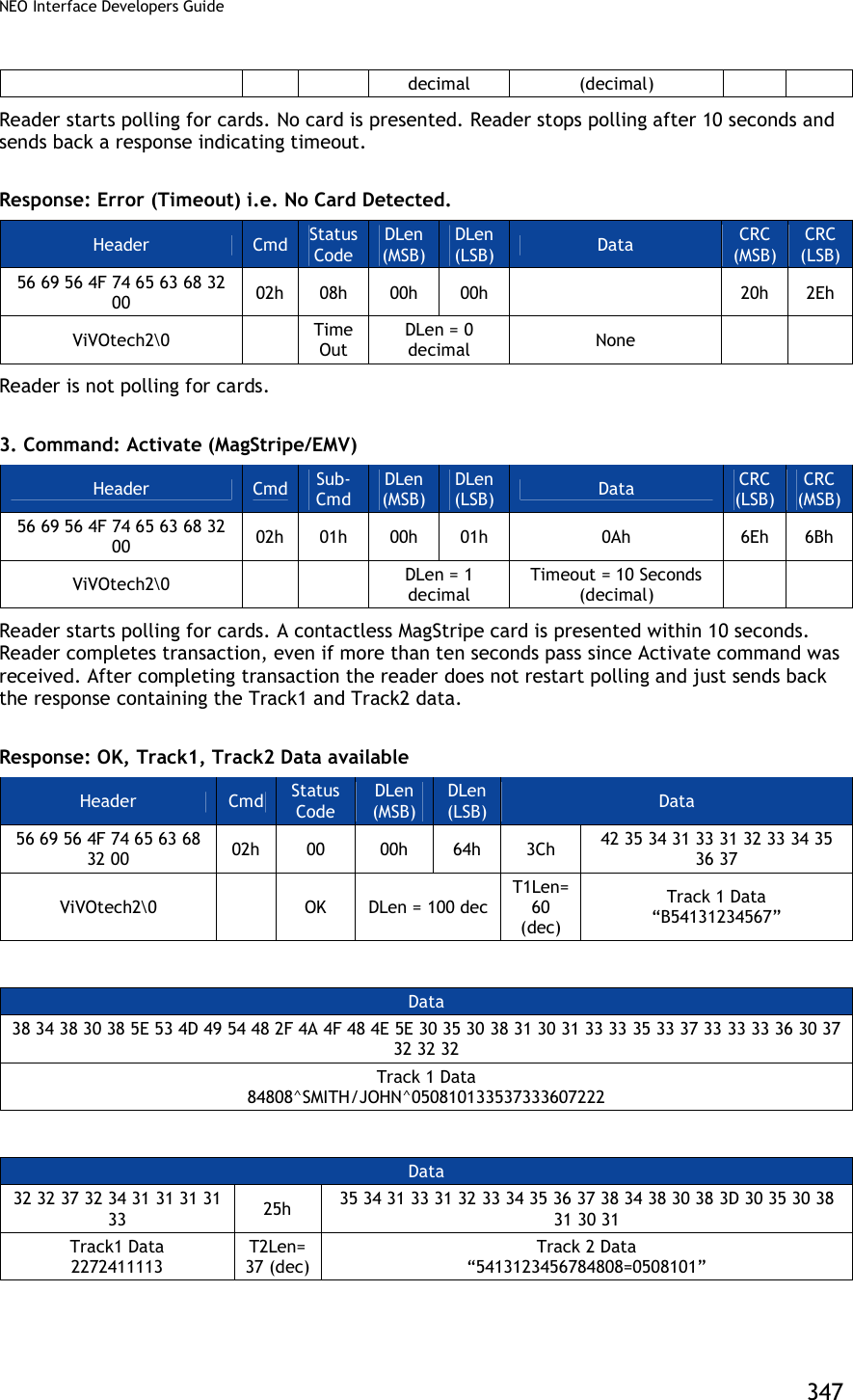
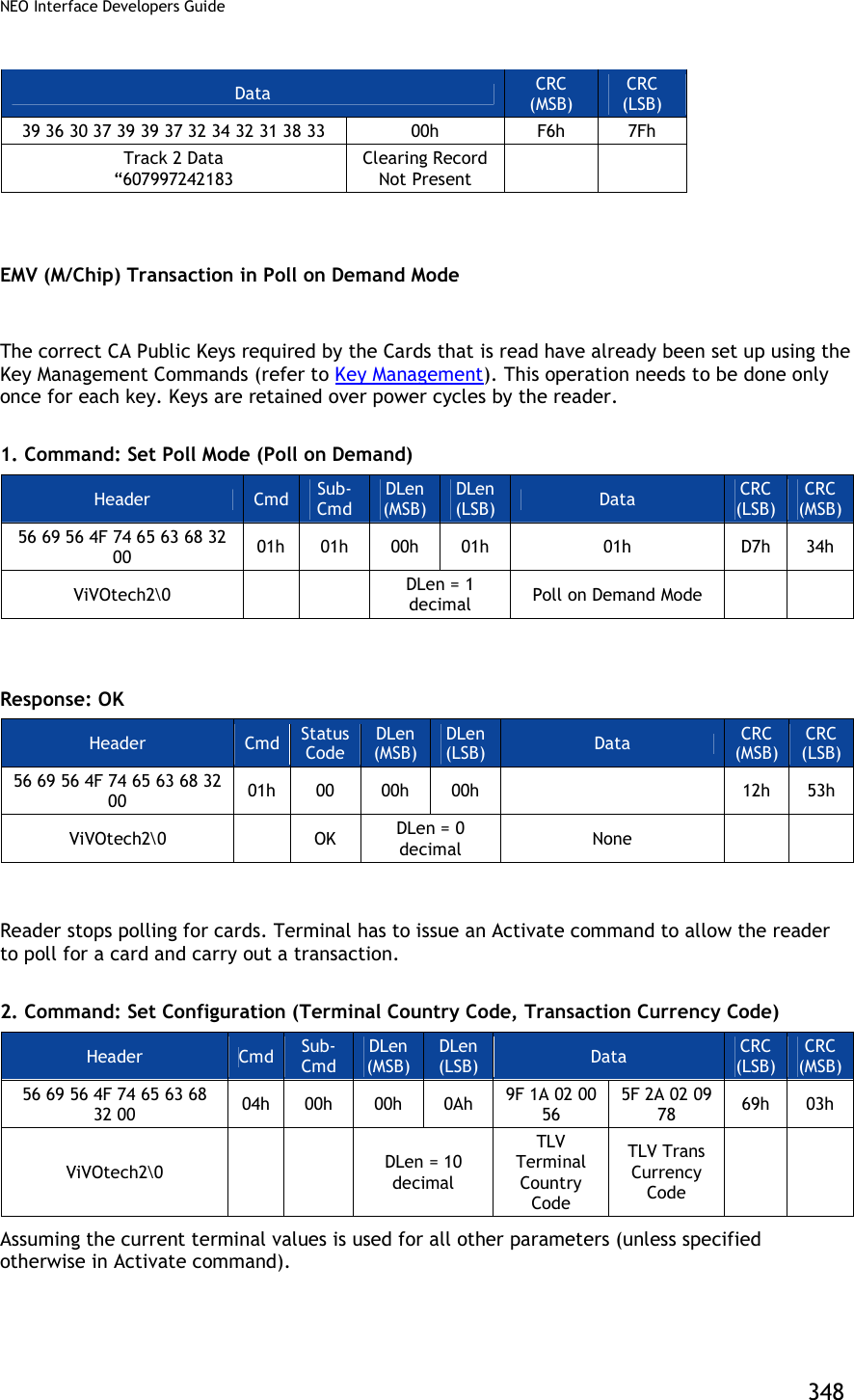
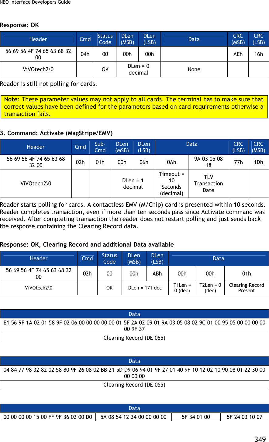
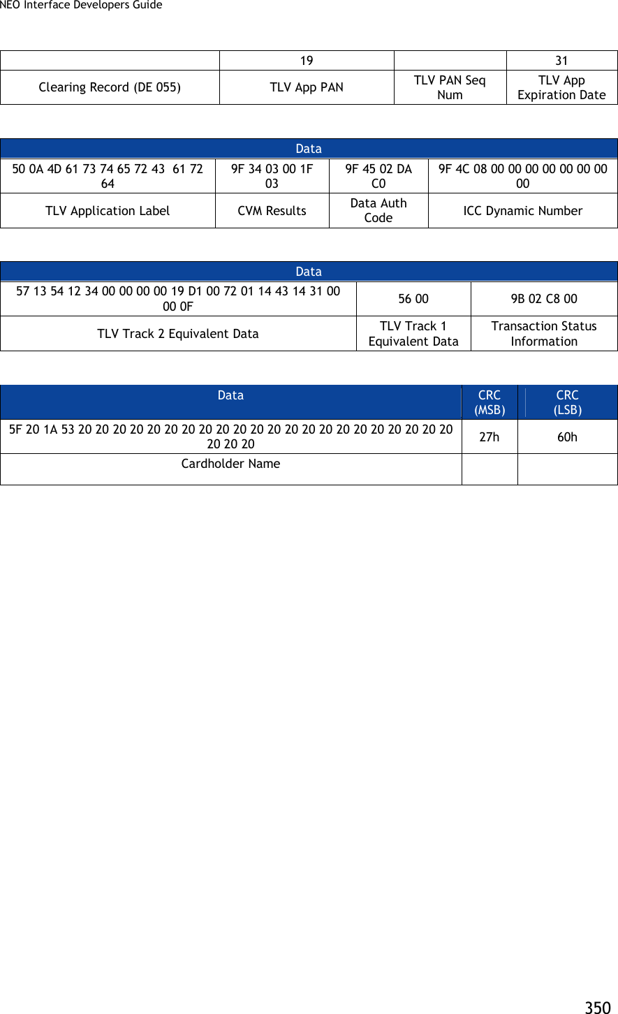
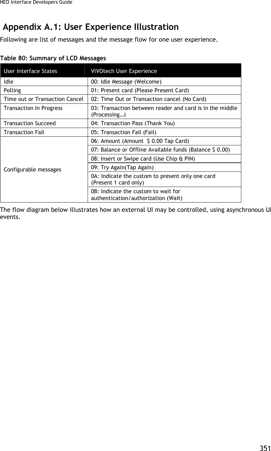
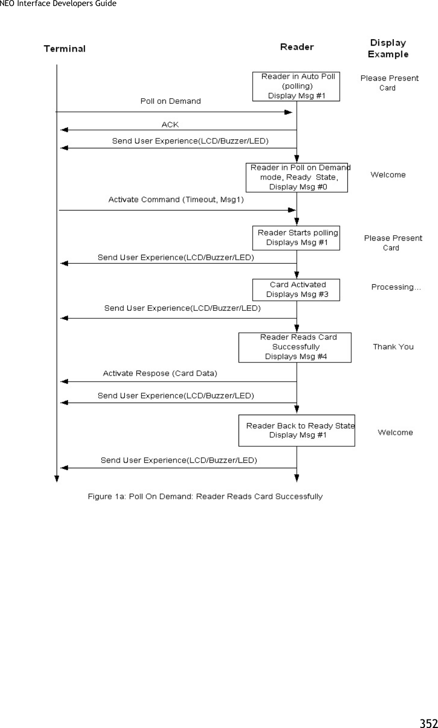
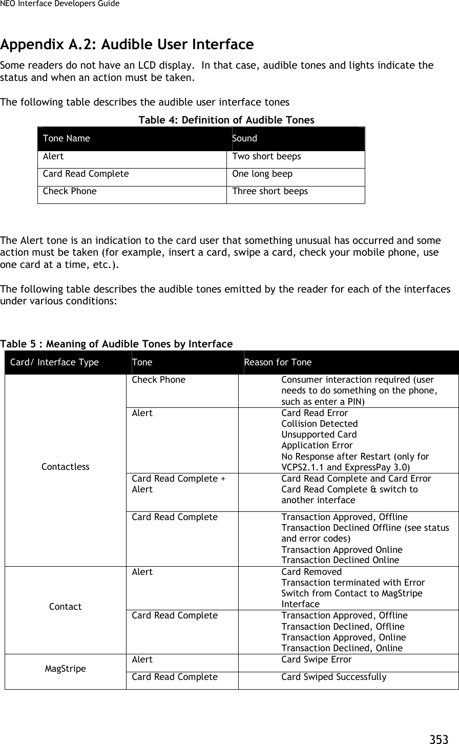
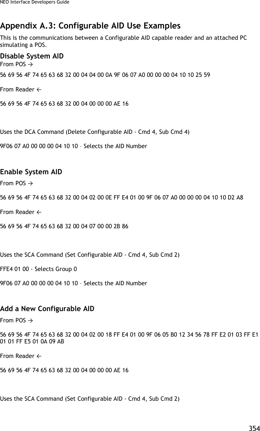
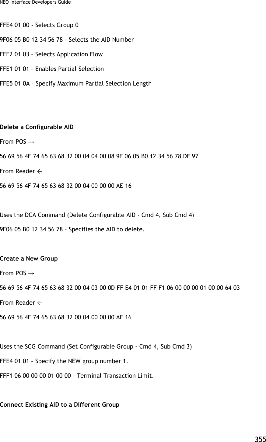
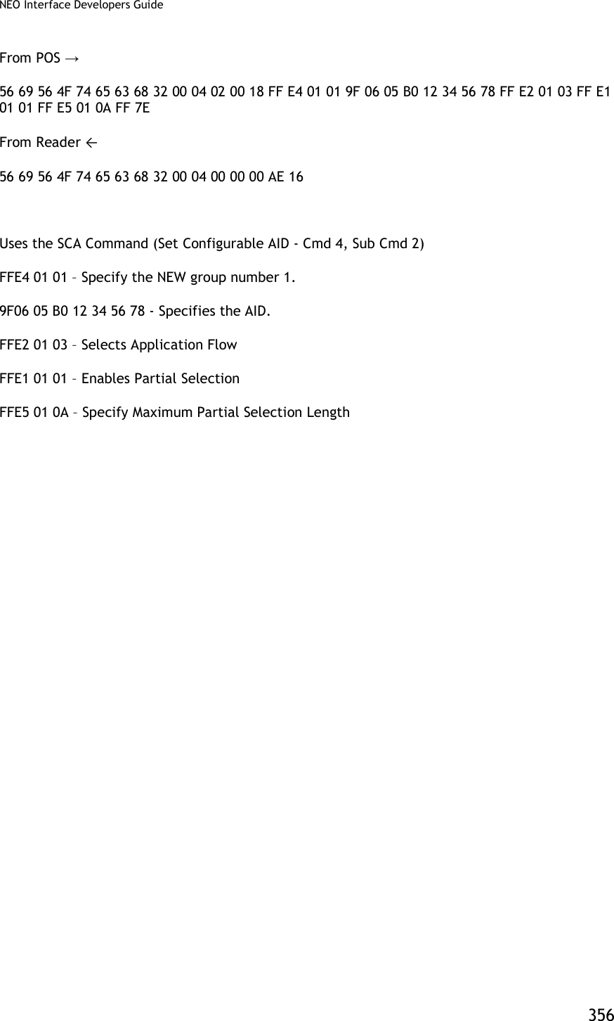
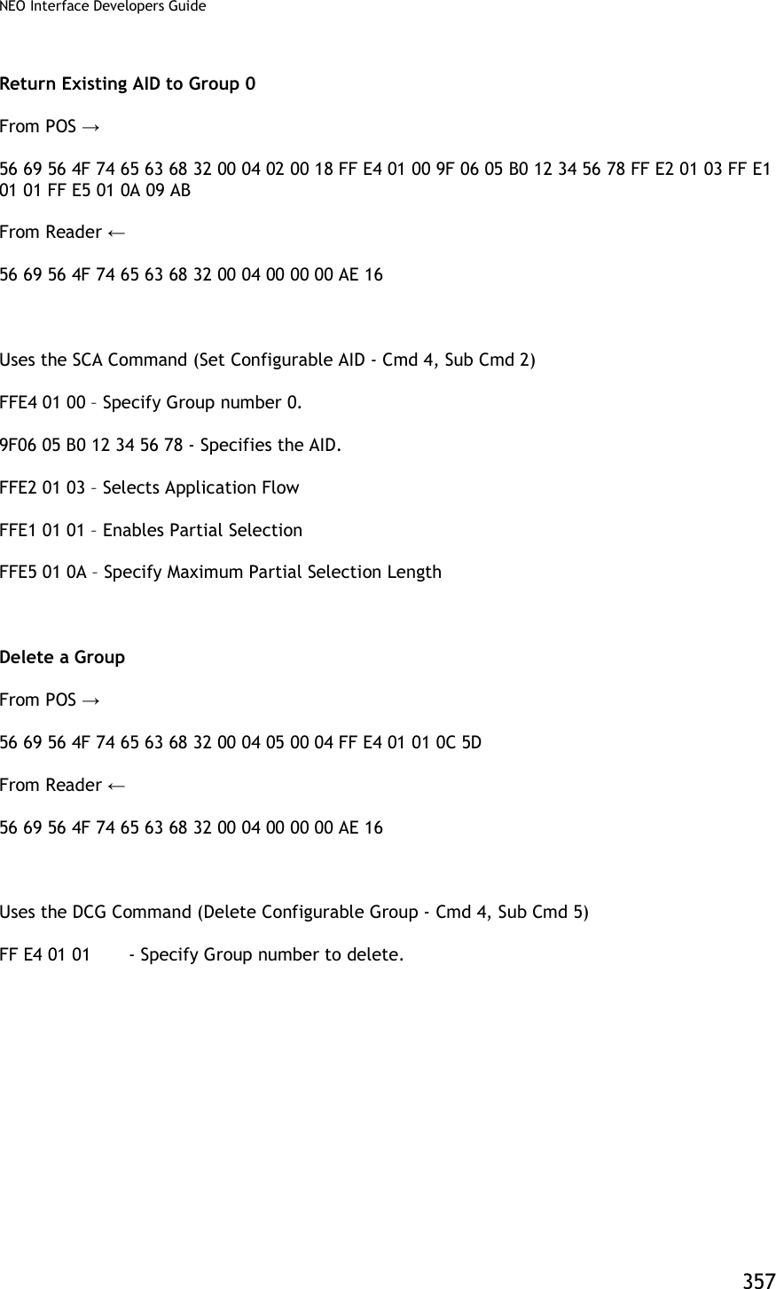
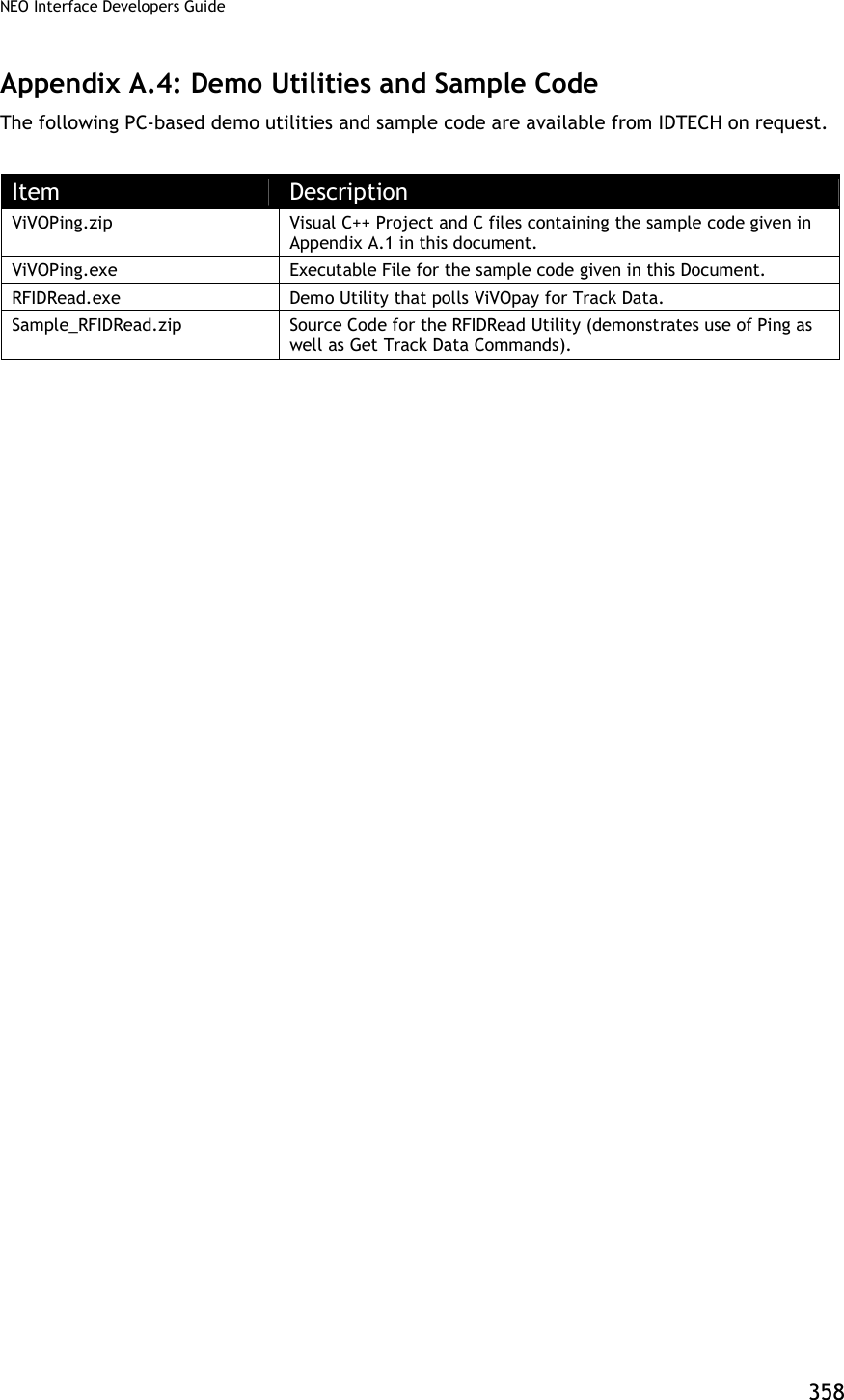
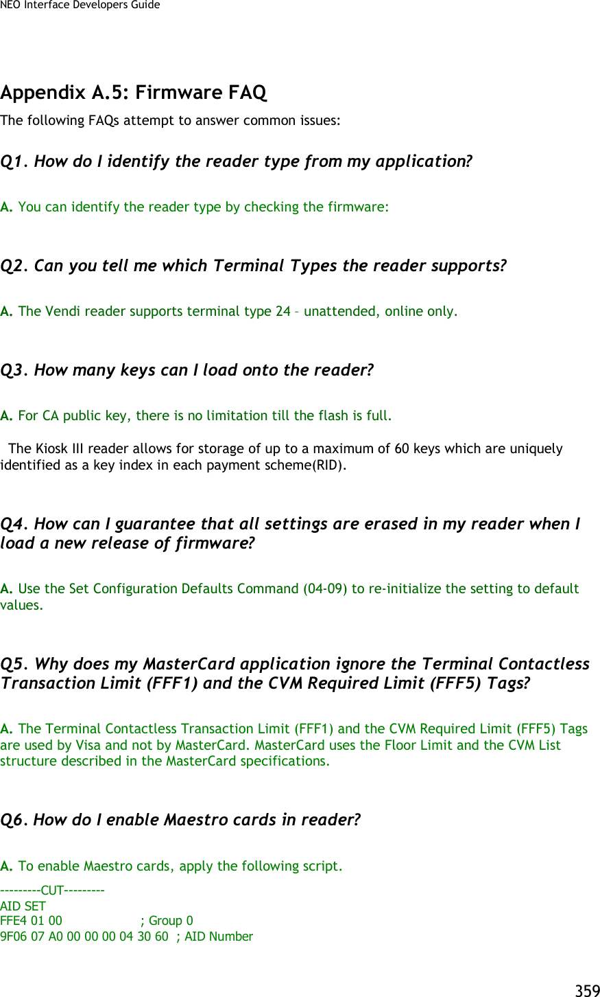
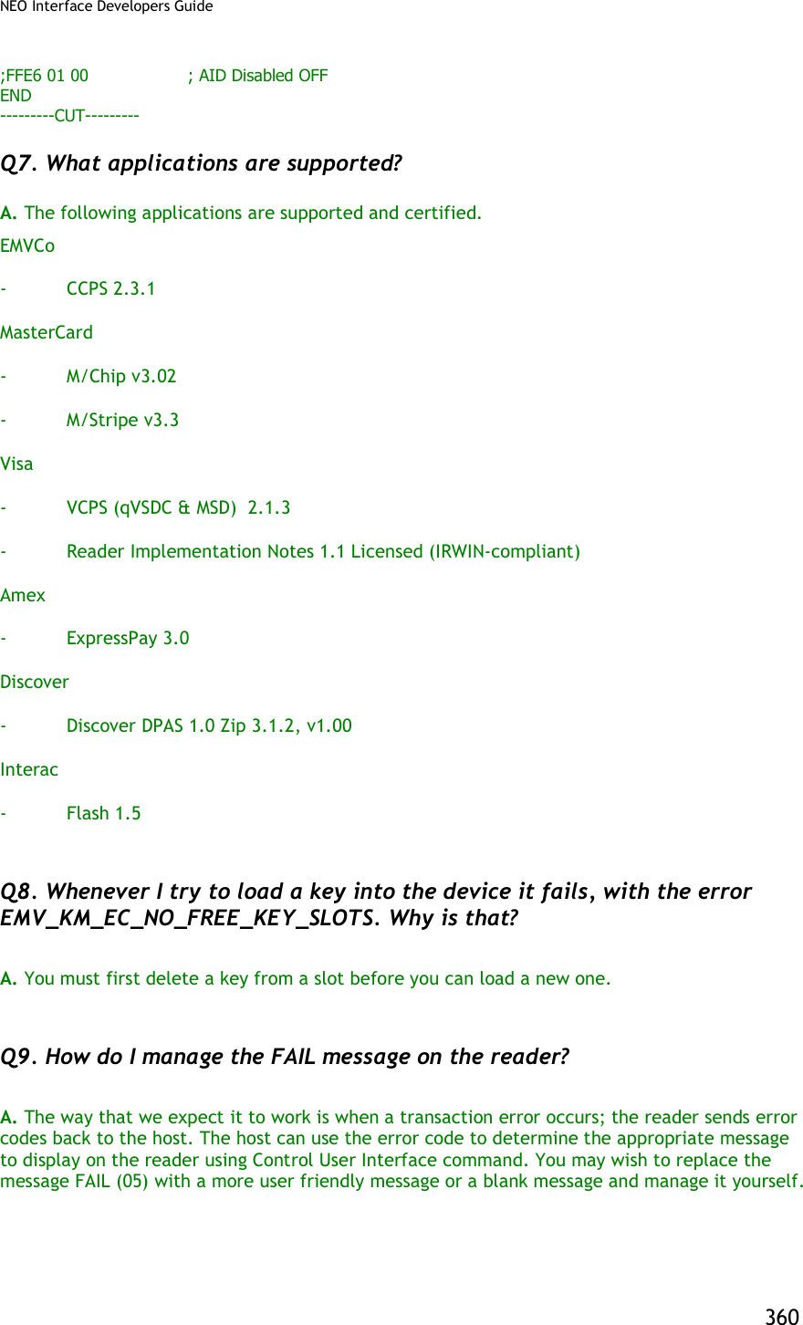
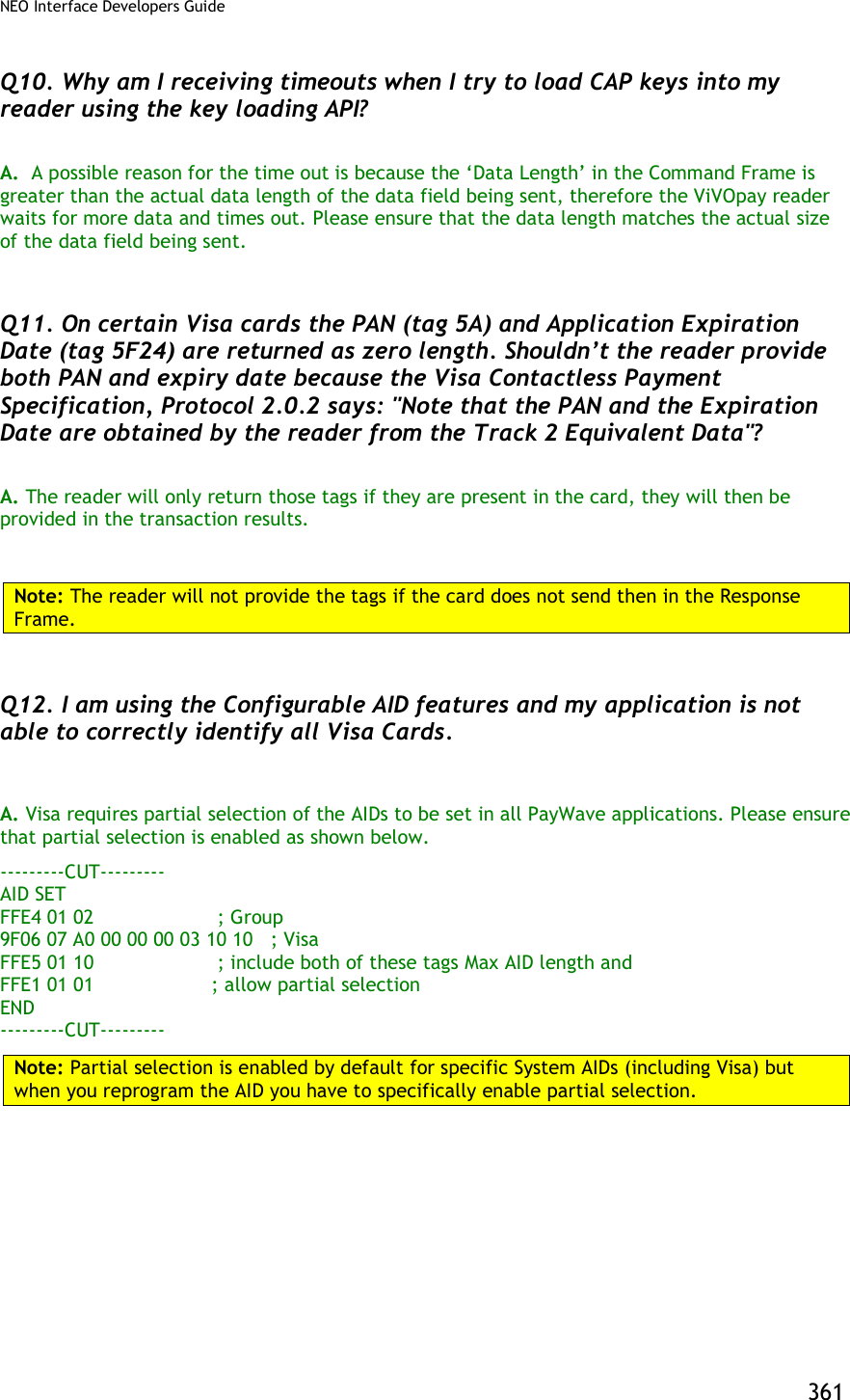

![NEO Interface Developers Guide 363 Appendix A.6: TDES Data Encryption Examples Examples are given for MSR data as well as ICC data. Note that data for the former will be in a different format than data for the latter. The former uses the Enhanced Encrypted MSR Data Output Format (see later appendix, or see ID TECH document P/N 80000403-001). By contrast, ICC data comes back as TLV data, preceded by a ViVOtech2 header with command and response bytes and two length bytes, and followed by a 16-bit CRC. Step 1: Data encryption Enable [TX] - 56 69 56 4F 74 65 63 68 32 00 C7 36 00 01 01 B7 2E [RX] - 56 69 56 4F 74 65 63 68 32 00 C7 00 00 00 86 6E Step 2: Do a transaction Example: Burst Mode OFF and Poll on Demand mode Burst off [TX] - 56 69 56 4F 74 65 63 68 32 00 04 00 00 04 FF F7 01 00 B9 2E [RX] - 56 69 56 4F 74 65 63 68 32 00 04 00 00 00 AE 16 Poll on demand [TX] - 56 69 56 4F 74 65 63 68 32 00 01 01 00 01 01 D7 34 [RX] - 56 69 56 4F 74 65 63 68 32 00 01 00 00 00 12 53 Activate transaction and then Swipe card or Tap card [TX] - 56 69 56 4F 74 65 63 68 32 00 02 01 00 0A 0A 9F 02 06 00 00 00 00 10 00 AB 6C [RX] - MSR and contactless Card DATA As below --MSR card data The data will come back in the Enhanced Encrypted MSR Data Output Format, framed as follows: <Preamble> <Attribution> < MSR TLV> <CRC> See Appendix A.11 for format details. Raw data: Raw data: 56 69 56 4F 74 65 63 68 32 00 Protocol Header (ViVOtech2\0) 02 Command 00 Status Code 01 3D Data Length MSB & LSB](https://usermanual.wiki/ID-TECH/VP3600/User-Guide-3704675-Page-375.png)
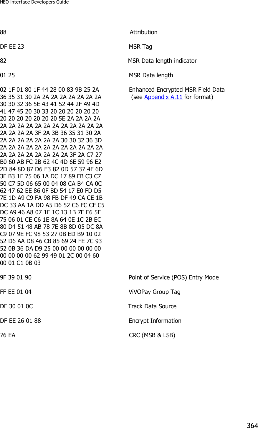
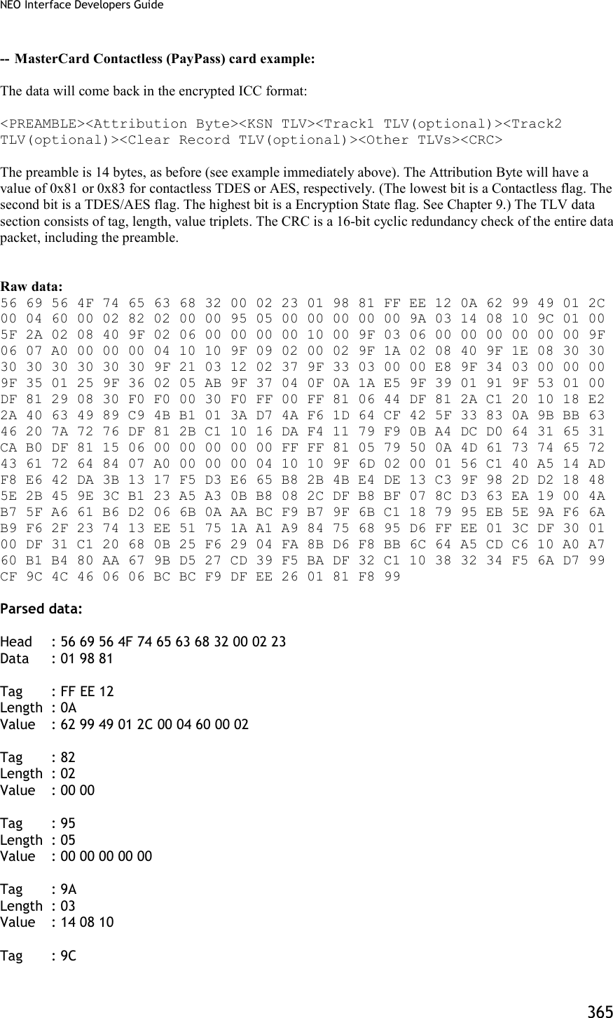
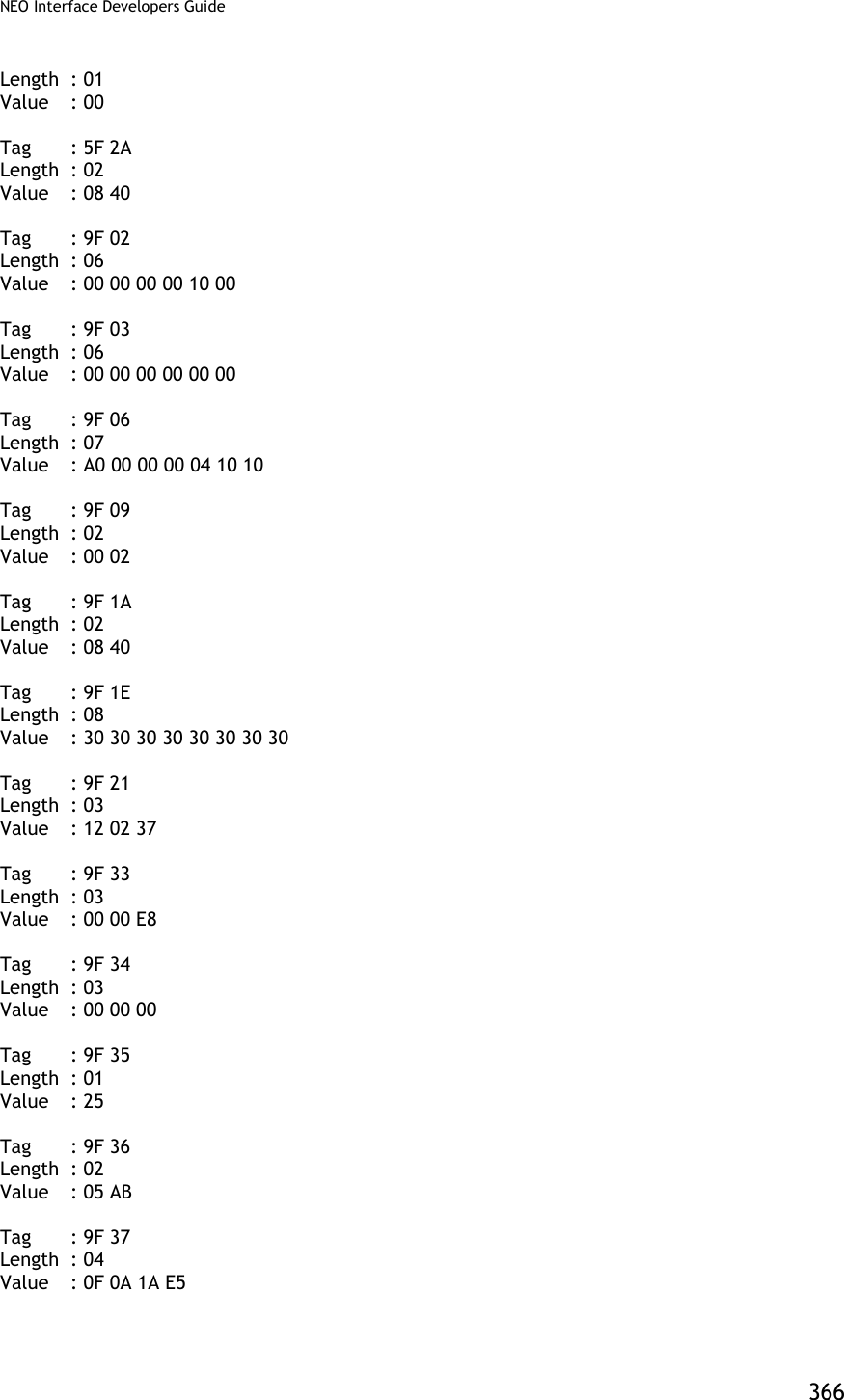
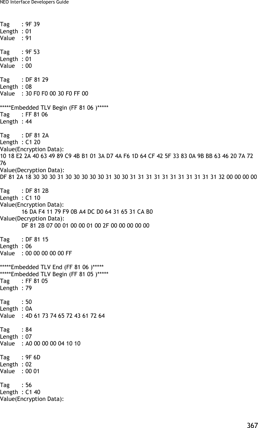
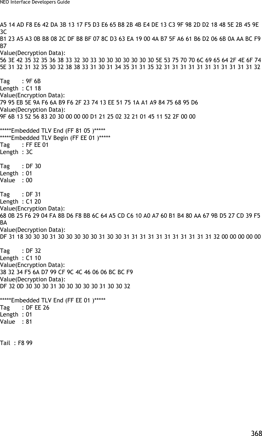
![NEO Interface Developers Guide 369 Burst Mode OFF and Auto Poll Mode Burst mode OFF [TX] - 56 69 56 4F 74 65 63 68 32 00 04 00 00 04 FF F7 01 00 B9 2E [RX] - 56 69 56 4F 74 65 63 68 32 00 04 00 00 00 AE 16 Auto poll [TX] - 56 69 56 4F 74 65 63 68 32 00 01 01 00 01 00 F6 24 [RX] - 56 69 56 4F 74 65 63 68 32 00 01 00 00 00 12 53 Swipe card or Tap card Get transaction result [TX] - 56 69 56 4F 74 65 63 68 32 00 03 00 00 00 3B FF [RX] -MSR and contactless Card DATA As below --MSR card data 56 69 56 4F 74 65 63 68 32 00 Protocol Header (ViVOtech2\0) 03 Command 00 Status Code 01 3D Data Length MSB & LSB 88 Attribution DF EE 23 MSR Tag 82 MSR Data length indicator 01 25 MSR Data length 02 1F 01 80 1F 44 28 00 83 9B 25 2A Enhanced Encrypted Field Data 36 35 31 30 2A 2A 2A 2A 2A 2A 2A 2A (see Appendix A.11 for format) 30 30 32 36 5E 43 41 52 44 2F 49 4D 41 47 45 20 30 33 20 20 20 20 20 20 20 20 20 20 20 20 20 5E 2A 2A 2A 2A 2A 2A 2A 2A 2A 2A 2A 2A 2A 2A 2A 2A 2A 2A 2A 2A 3F 2A 3B 36 35 31 30 2A 2A 2A 2A 2A 2A 2A 2A 30 30 32 36 3D 2A 2A 2A 2A 2A 2A 2A 2A 2A 2A 2A 2A 2A 2A 2A 2A 2A 2A 2A 2A 3F 2A C7 27 B0 60 AB FC 2B 62 4C 4D 6E 59 96 E2 2D 84 8D 87 D6 E3 82 0D 57 37 4F 6D 3F B3 1F 75 06 1A DC 17 89 FB C3 C7 50 C7 5D 06 65 00 04 08 CA B4 CA 0C 62 47 62 EE 86 0F BD 54 17 E0 FD D5 7E 1D A9 C9 FA 98 FB DF 49 CA CE 1B DC 33 AA 1A DD A5 D6 52 C6 FC CF C5 DC A9 46 A8 07 1F 1C 13 1B 7F E6 5F](https://usermanual.wiki/ID-TECH/VP3600/User-Guide-3704675-Page-381.png)
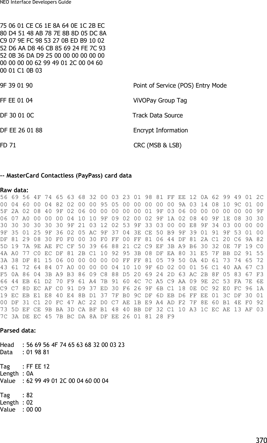
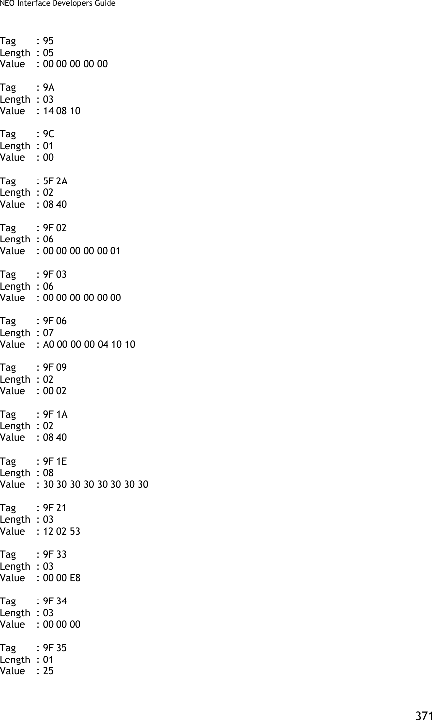
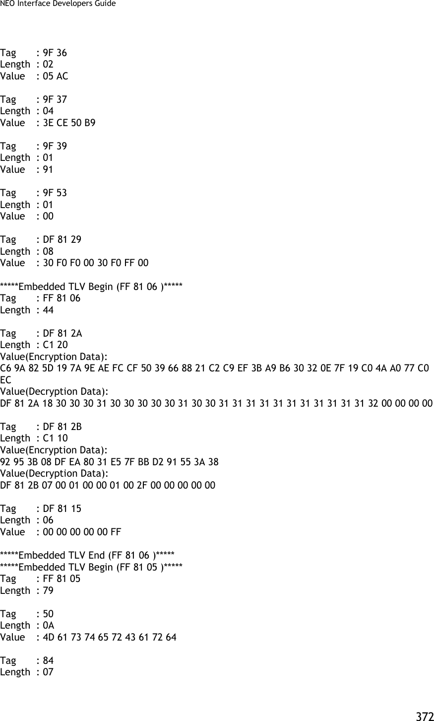
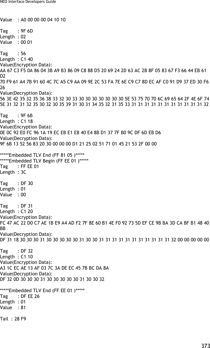
![NEO Interface Developers Guide 374 Appendix A.7: AES Data Encryption Examples Examples are given for MSR data as well as ICC data. Note that data for the former will be in a different format than data for the latter. The former uses the Enhanced Encrypted MSR Data Output Format (see later appendix, or see ID TECH document P/N 80000403-001). By contrast, ICC data comes back as TLV data, preceded by a ViVOtech2 header with command and response bytes and two length bytes, and followed by a 16-bit CRC. Step 1 Data encryption Enable [TX] - 56 69 56 4F 74 65 63 68 32 00 C7 36 00 01 01 B7 2E [RX] - 56 69 56 4F 74 65 63 68 32 00 C7 00 00 00 86 6E Step 2 Do a transaction Burst Mode OFF and Poll on Demand Mode Burst off [TX] - 56 69 56 4F 74 65 63 68 32 00 04 00 00 04 FF F7 01 00 B9 2E [RX] - 56 69 56 4F 74 65 63 68 32 00 04 00 00 00 AE 16 Poll on demand [TX] - 56 69 56 4F 74 65 63 68 32 00 01 01 00 01 01 D7 34 [RX] - 56 69 56 4F 74 65 63 68 32 00 01 00 00 00 12 53 Activate transaction and then Swipe card or Tap card [TX] - 56 69 56 4F 74 65 63 68 32 00 02 01 00 0A 0A 9F 02 06 00 00 00 00 10 00 AB 6C [RX] - MSR and contactless Card DATA As below --MSR card data 56 69 56 4F 74 65 63 68 32 00 Protocol Header (ViVOtech2\0) 02 Command 00 Status Code 01 4D Data Length MSB & LSB 8A Attribution DF EE 23 MSR Tag 82 MSR Data length indicator 01 35 MSR Data length 02 2F 01 80 1F 44 28 00 93 9B 25 2A Enhanced Encrypted MSR Field Data 36 35 31 30 2A 2A 2A 2A 2A 2A 2A 2A (see Appendix A.11 for format)](https://usermanual.wiki/ID-TECH/VP3600/User-Guide-3704675-Page-386.png)
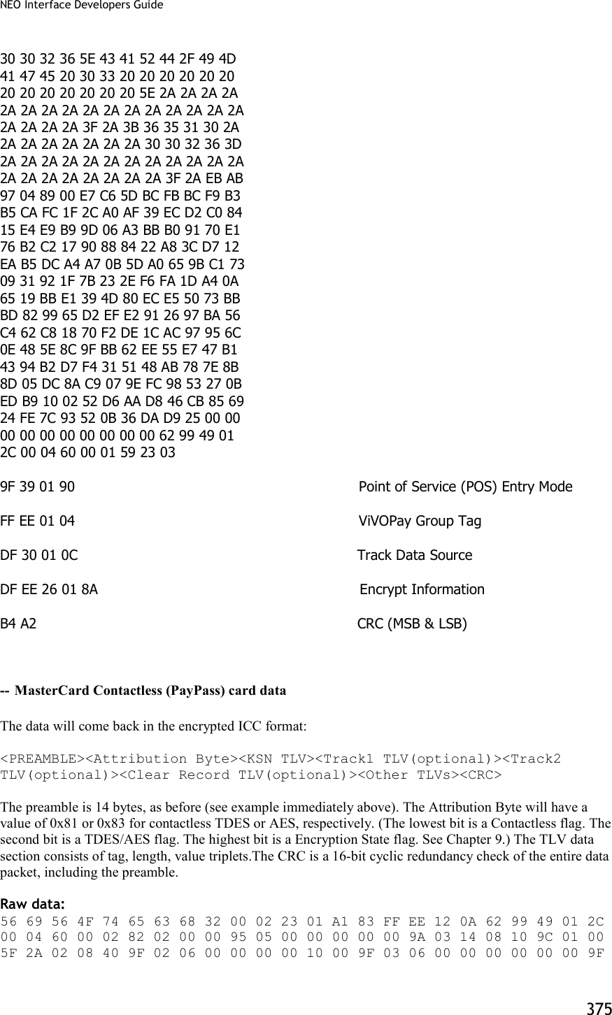
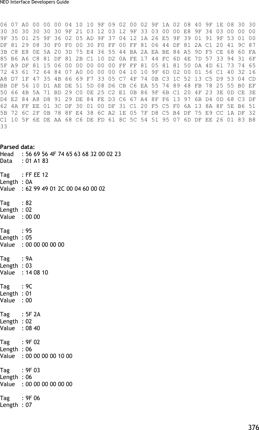
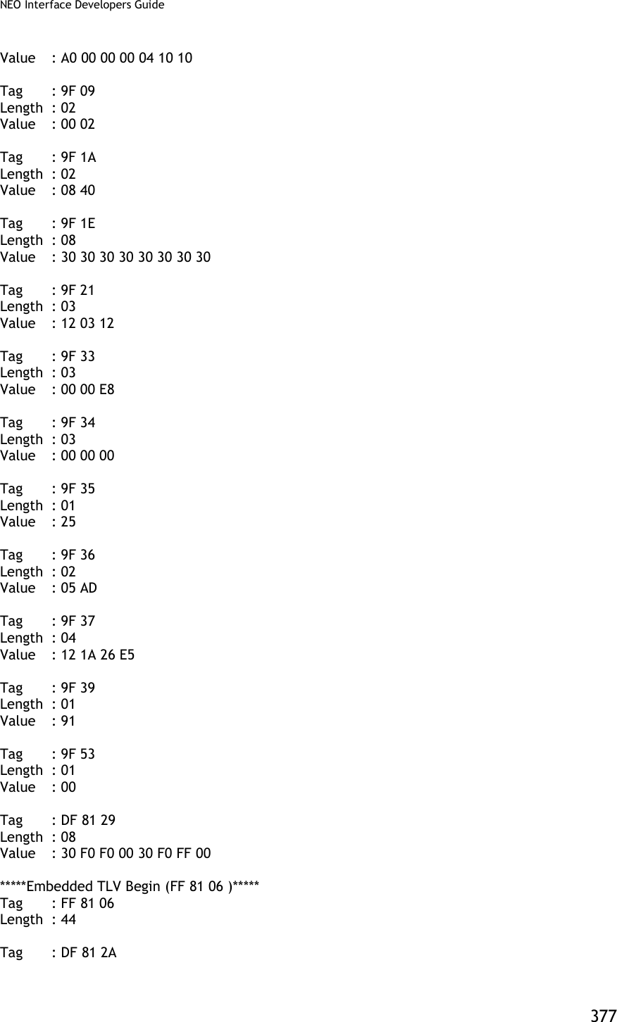
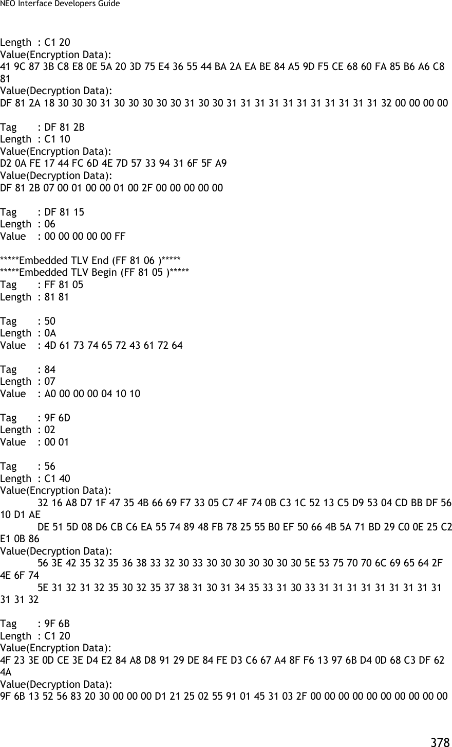
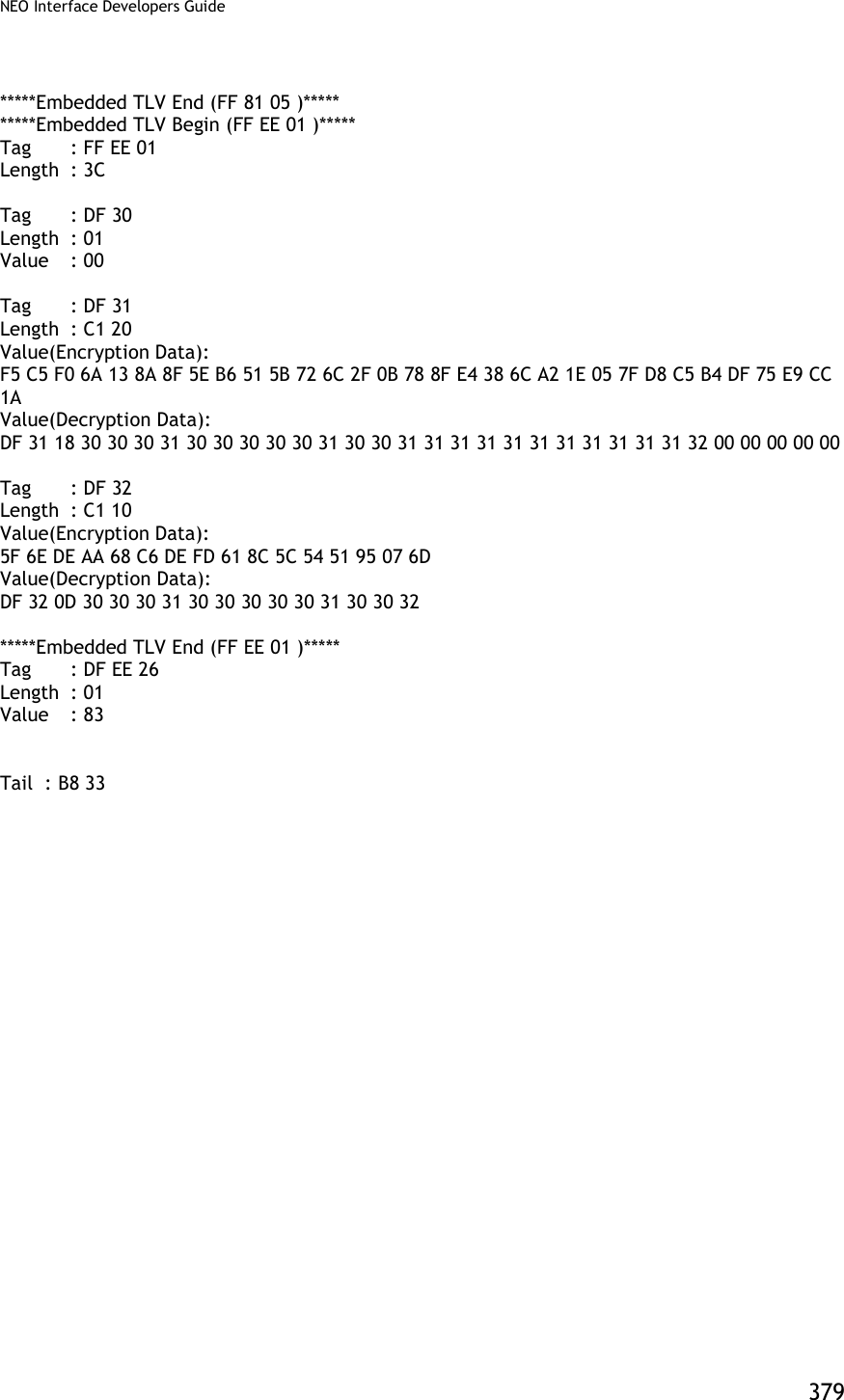
![NEO Interface Developers Guide 380 Burst Mode OFF and Auto Poll Mode Burst mode OFF [TX] - 56 69 56 4F 74 65 63 68 32 00 04 00 00 04 FF F7 01 00 B9 2E [RX] - 56 69 56 4F 74 65 63 68 32 00 04 00 00 00 AE 16 Auto poll [TX] - 56 69 56 4F 74 65 63 68 32 00 01 01 00 01 00 F6 24 [RX] - 56 69 56 4F 74 65 63 68 32 00 01 00 00 00 12 53 Swipe card or Tap card Get transaction result [TX] - 56 69 56 4F 74 65 63 68 32 00 03 00 00 00 3B FF [RX] MSR and contactless Card DATA As below --MSR card data 56 69 56 4F 74 65 63 68 32 00 Protocol Header (ViVOtech2\0) 03 Command 00 Status Code 01 4D Data Length MSB & LSB 8A Attribution DF EE 23 MSR Tag 82 MSR Data length indicator 01 35 MSR Data length 02 2F 01 80 1F 44 28 00 93 9B 25 2A Enhanced Encrypted MSR Field Data 36 35 31 30 2A 2A 2A 2A 2A 2A 2A 2A (see Appendix A.11 for format) 30 30 32 36 5E 43 41 52 44 2F 49 4D 41 47 45 20 30 33 20 20 20 20 20 20 20 20 20 20 20 20 20 5E 2A 2A 2A 2A 2A 2A 2A 2A 2A 2A 2A 2A 2A 2A 2A 2A 2A 2A 2A 2A 3F 2A 3B 36 35 31 30 2A 2A 2A 2A 2A 2A 2A 2A 30 30 32 36 3D 2A 2A 2A 2A 2A 2A 2A 2A 2A 2A 2A 2A 2A 2A 2A 2A 2A 2A 2A 2A 3F 2A EB AB 97 04 89 00 E7 C6 5D BC FB BC F9 B3 B5 CA FC 1F 2C A0 AF 39 EC D2 C0 84 15 E4 E9 B9 9D 06 A3 BB B0 91 70 E1 76 B2 C2 17 90 88 84 22 A8 3C D7 12 EA B5 DC A4 A7 0B 5D A0 65 9B C1 73 09 31 92 1F 7B 23 2E F6 FA 1D A4 0A](https://usermanual.wiki/ID-TECH/VP3600/User-Guide-3704675-Page-392.png)
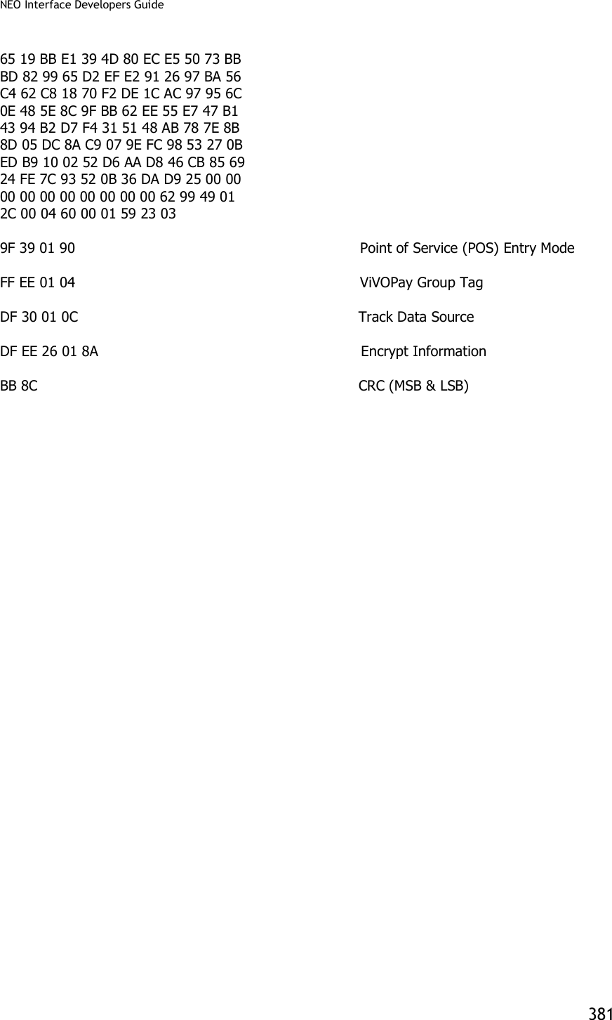
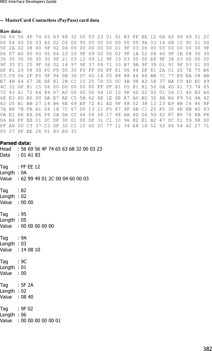
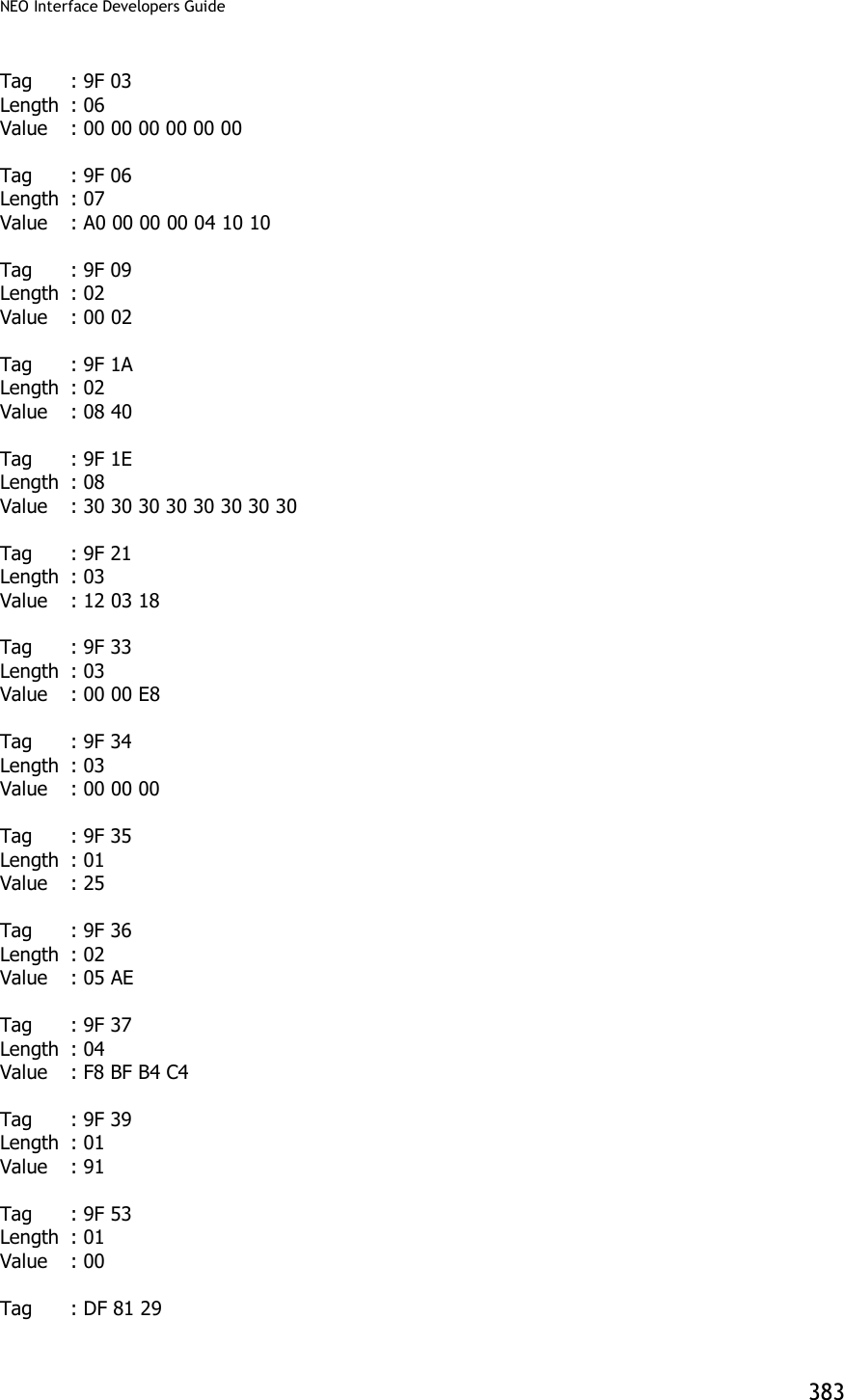
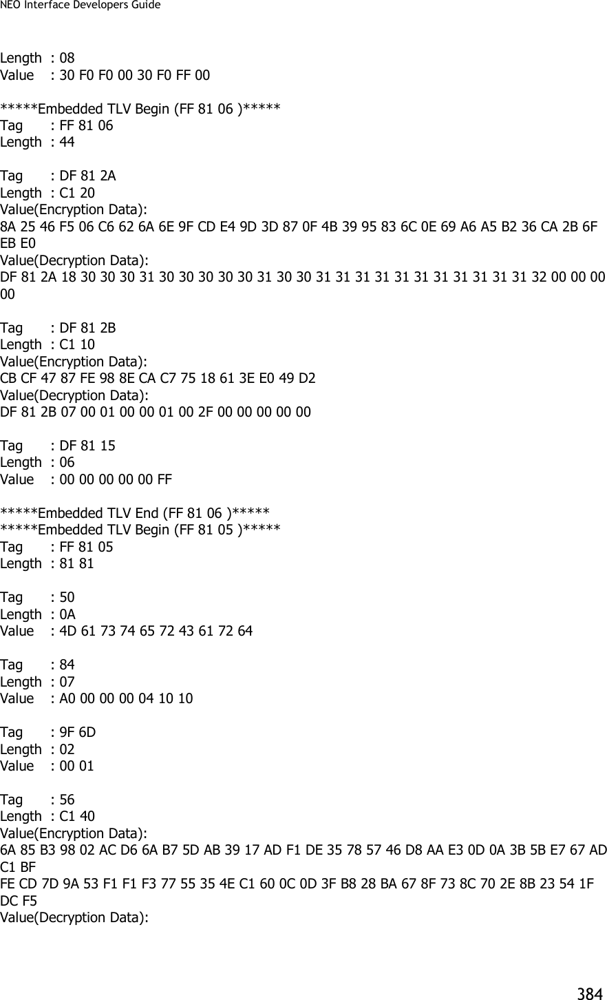
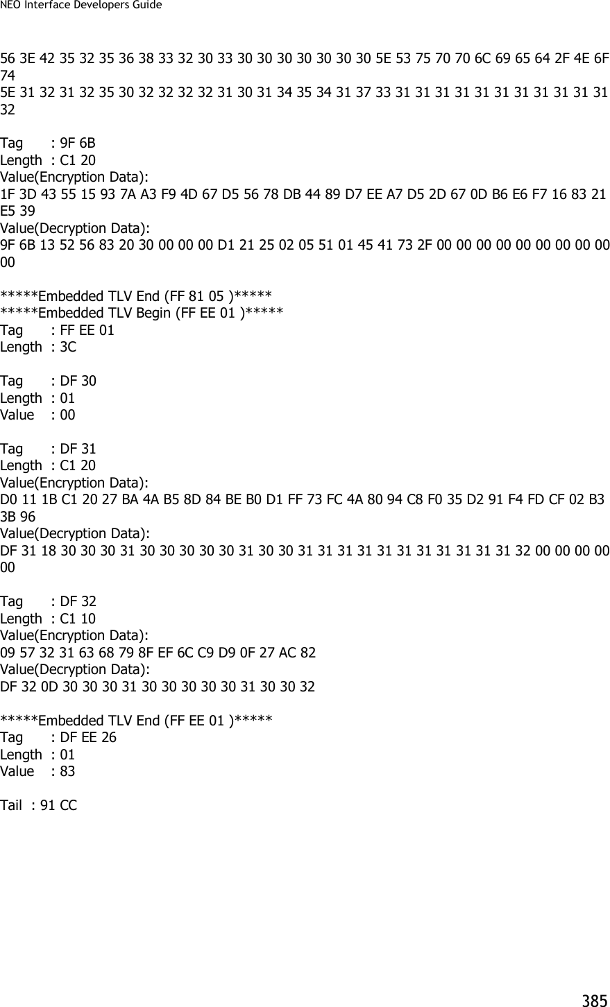
![NEO Interface Developers Guide 386 Appendix A.8: Transaction Results for MSD2.0.2 AC3.0 Cryptogram17 The following provides information on the transaction results returned for MSD2.0.2 AC3.0 Cryptogram17 transaction. [Header] 56 69 56 4F 74 65 63 68 32 00 [Command byte] 02 [Status Code] 23 [Length] 01 66 [T1] 4C 42 34 30 30 35 35 37 38 30 30 30 30 33 38 36 36 33 5E 43 41 52 44 48 4F 4C 44 45 52 2F 56 49 53 41 5E 31 30 31 32 32 30 31 30 31 32 33 34 30 31 32 33 34 30 30 30 30 30 30 30 30 30 30 35 35 36 31 30 31 31 32 33 36 35 30 30 30 30 [T2] 25 34 30 30 35 35 37 38 30 30 30 30 33 38 36 36 33 3D 31 30 31 32 32 30 31 30 31 32 33 34 31 32 33 30 31 36 35 31 [Clearing Record present] 01 [Clearing Record] E1 7C 9F 66 04 80 80 00 00 9F 02 06 00 00 00 00 01 00 9F 37 04 02 45 70 24 5F 2A 02 08 40 9F 26 08 74 13 75 A7 11 47 47 93 9F 10 07 06 01 11 03 A0 00 00 9F 36 02 00 A5 9A 03 01 10 29 9C 01 22 95 05 00 00 00 00 00 82 02 00 80 9F 1A 02 08 40 9F 03 06 00 00 00 00 00 00 9F 6E 04 00 00 00 01 9F 7C 1B 00 06 49 53 53 55 45 52 00 0B 50 52 4F 50 52 49 45 54 41 52 59 00 04 44 41 54 41 [End of clearing record] 9F 6C 00 5A 00 5F 34 01 01 5F 24 00 50 0B 56 49 53 41 20 43 52 45 44 49 54 57 13 40 05 57 80 00 03 86 63 D1 01 22 01 01 23 41 23 01 65 1F 56 00 9B 02 00 00 5F 20 0F 43 41 52 44 48 4F 4C 44 45 52 2F 56 49 53 41 9F 07 00 9F 0D 05 FF FF FF FF FF 9F 0E 05 00 00 00 00 00 9F 0F 05 FF FF FF FF FF 9F 06 07 A0 00 00 00 03 10 10 9F 5D 00 9F 74 00 5F 25 00 [CRC] 4D 0D](https://usermanual.wiki/ID-TECH/VP3600/User-Guide-3704675-Page-398.png)
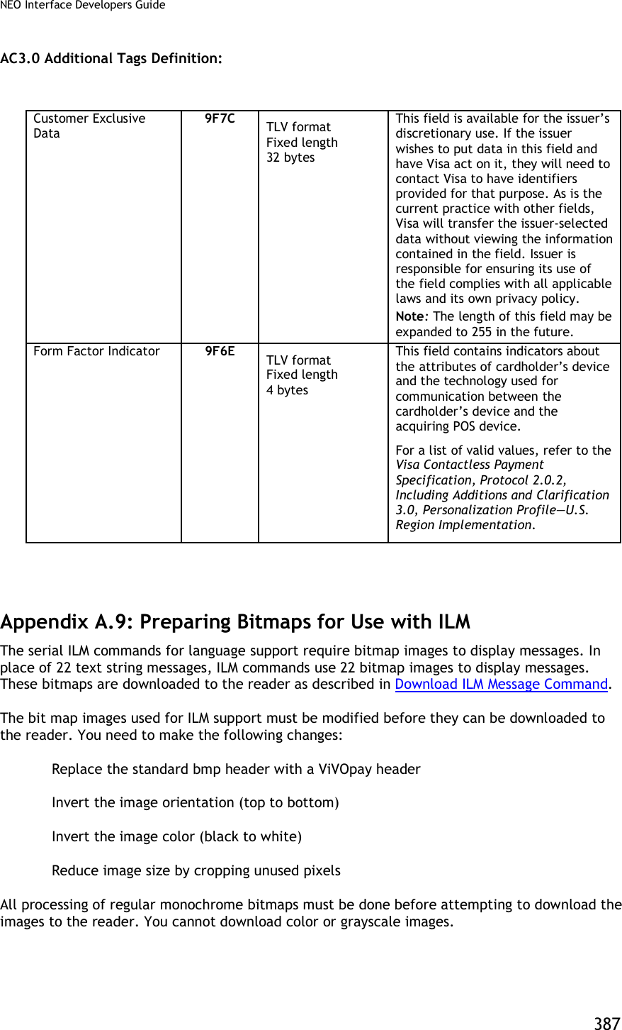
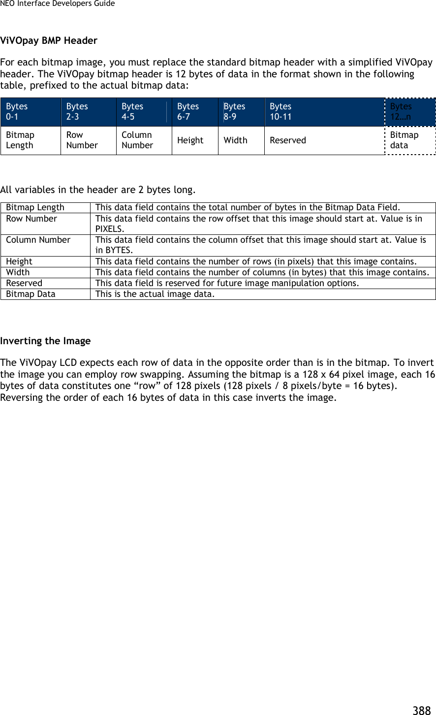
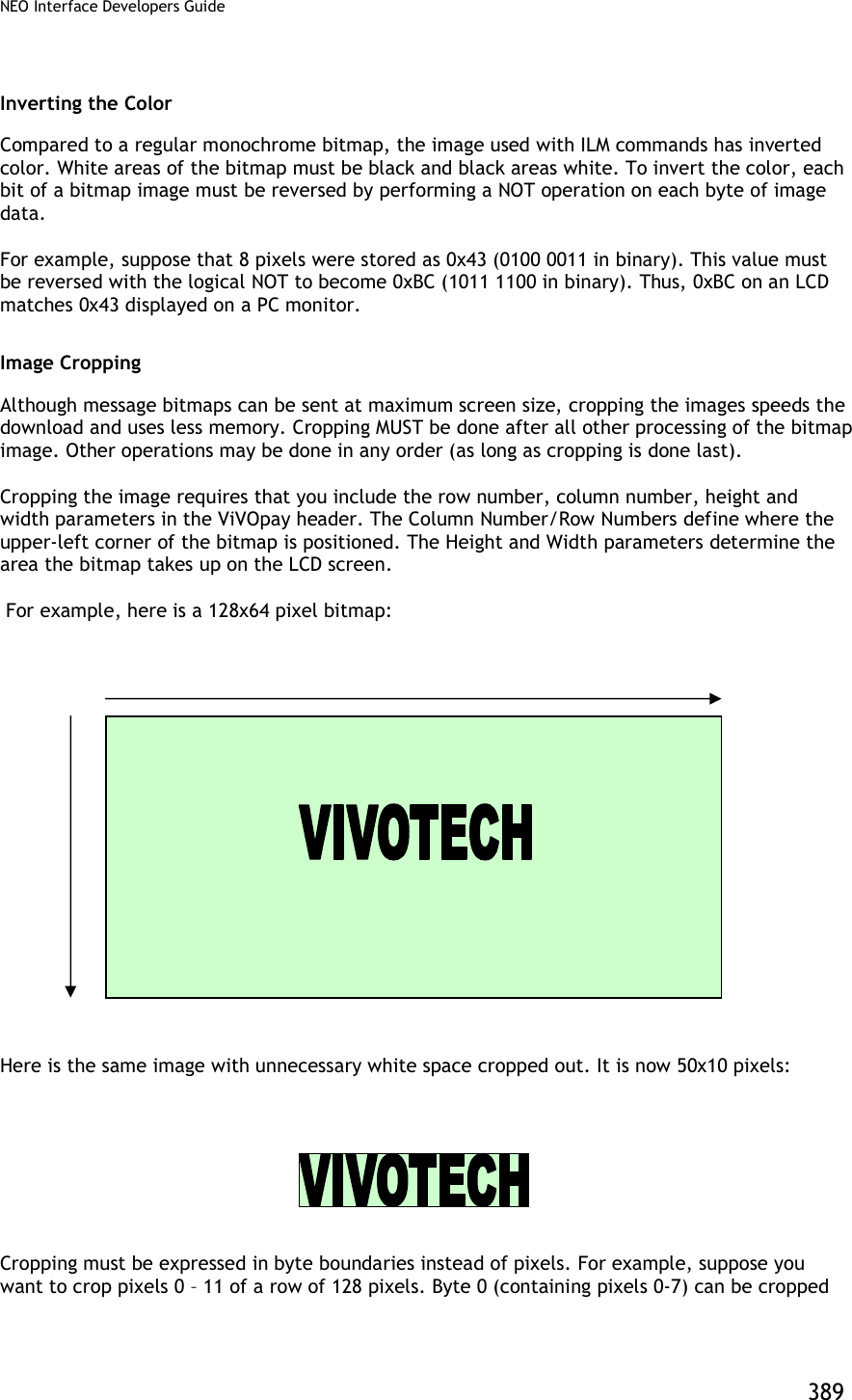
![NEO Interface Developers Guide 391 The following diagram shows how the header parameters are derived. The Row Number refers to the number of rows, each of which is a row of pixels. The Column Number refers to a byte location. So Row varies from 0 to 63, and the Column varies from 0 to 15. Example The following is a simple example of a bitmap which measures 24x4 pixels (24 pixels per row, 4 rows). All bitmap values shown are arbitrary (and in hexadecimal). Note: This example does NOT include image cropping. ACTUAL BMP: [14-byte BMP file header] + [40 byte DIB header] + [Bitmap Data = (11 00 00 00) (22 00 01 00) (33 00 01 00) (44 00 00 00)] First remove the headers. [Bitmap Data = (11 00 00 00) (22 00 01 00) (33 00 01 00) (44 00 00 00)] Then invert the image by swapping the rows. In this example, each row is 32 bits, i.e., 4 bytes long. Row 1 is swapped with the last row (4), Row 2 is swapped with the next-to-last row (3) and so on. 0 1 2 . . . . 62 63 0 1](https://usermanual.wiki/ID-TECH/VP3600/User-Guide-3704675-Page-403.png)
![NEO Interface Developers Guide 392 [Bitmap Data = (44 00 00 00) (33 00 01 00) (22 00 01 00) (11 00 00 00)] Next reverse the bits. [Bitmap Data = (BB FF FF FF) (CC FF FE FF) (DD FF FE FF) (EE FF FF FF)] Analyze the image. If the image needs to be cropped for white space reduction, do it now. Calculate positioning parameters and generate the ILM header. [12 byte ILM header] + [Bitmap Data = [BB FF FF FF] [CC FF FE FF] [DD FF FE FF] [EE FF FF FF]] This modified image data is now ready to be displayed or stored on the ViVOpay LCD.](https://usermanual.wiki/ID-TECH/VP3600/User-Guide-3704675-Page-404.png)
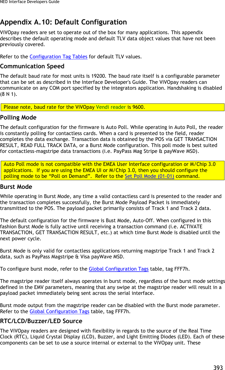
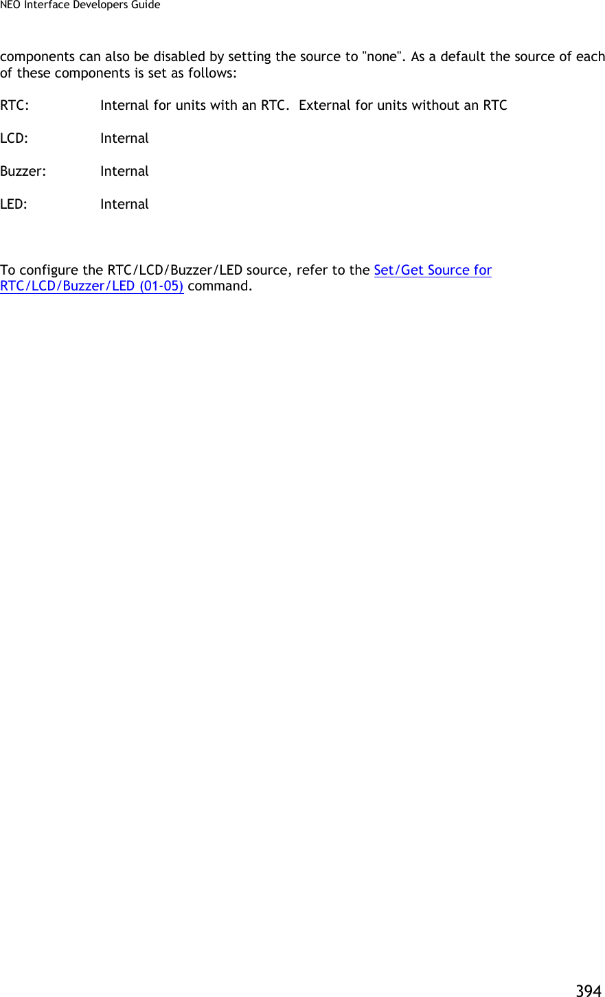
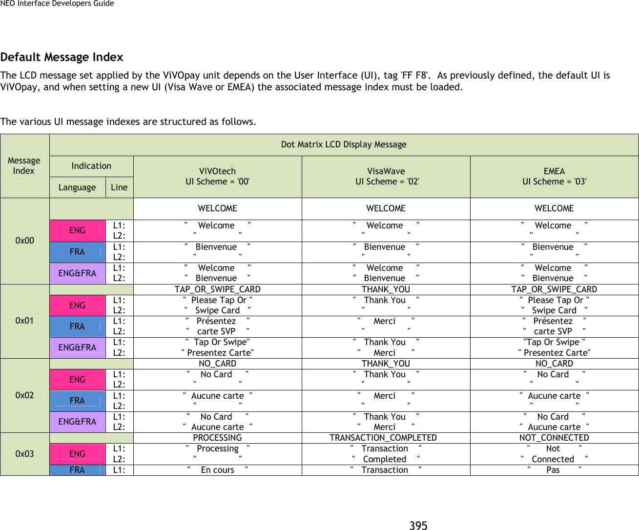
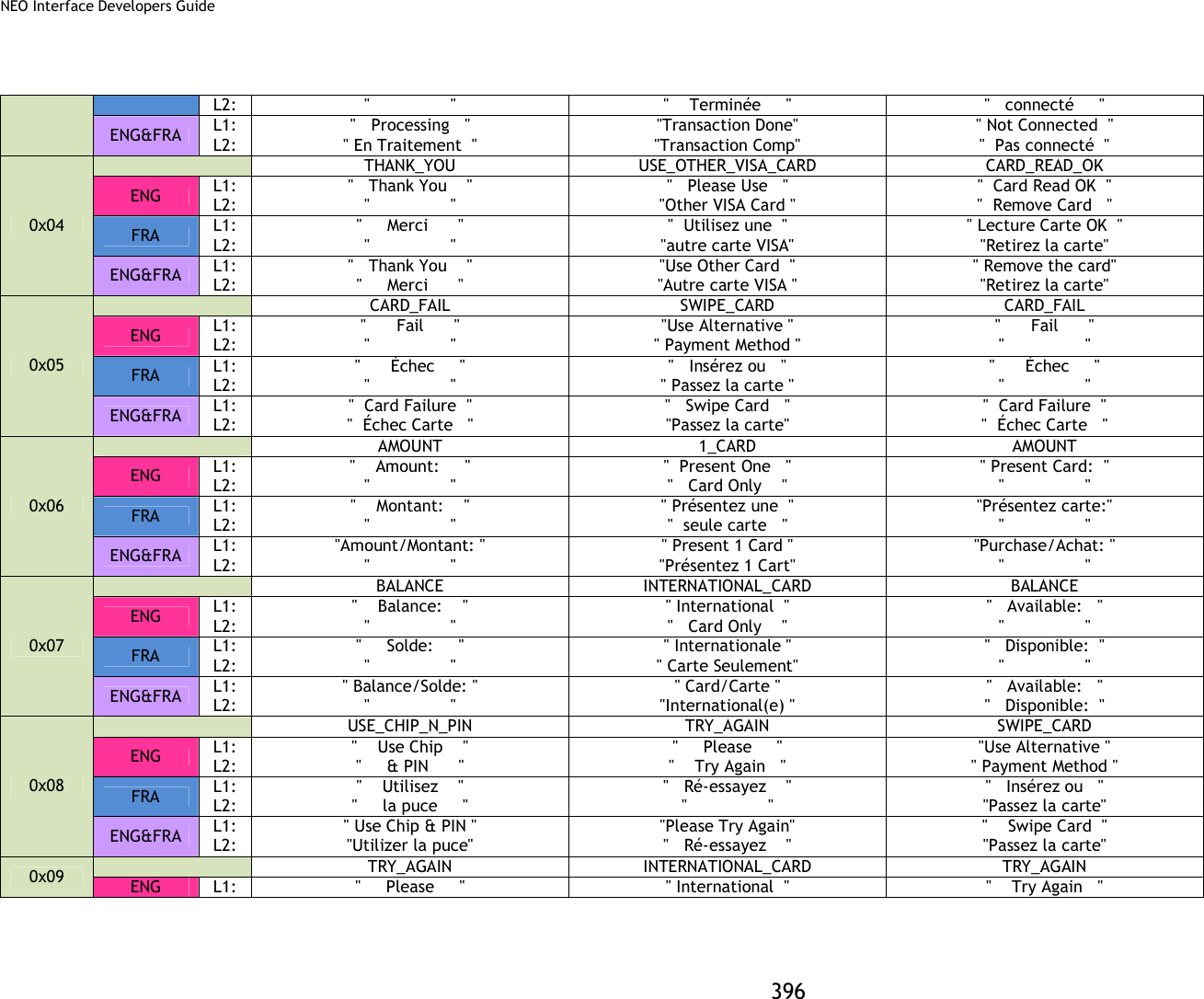
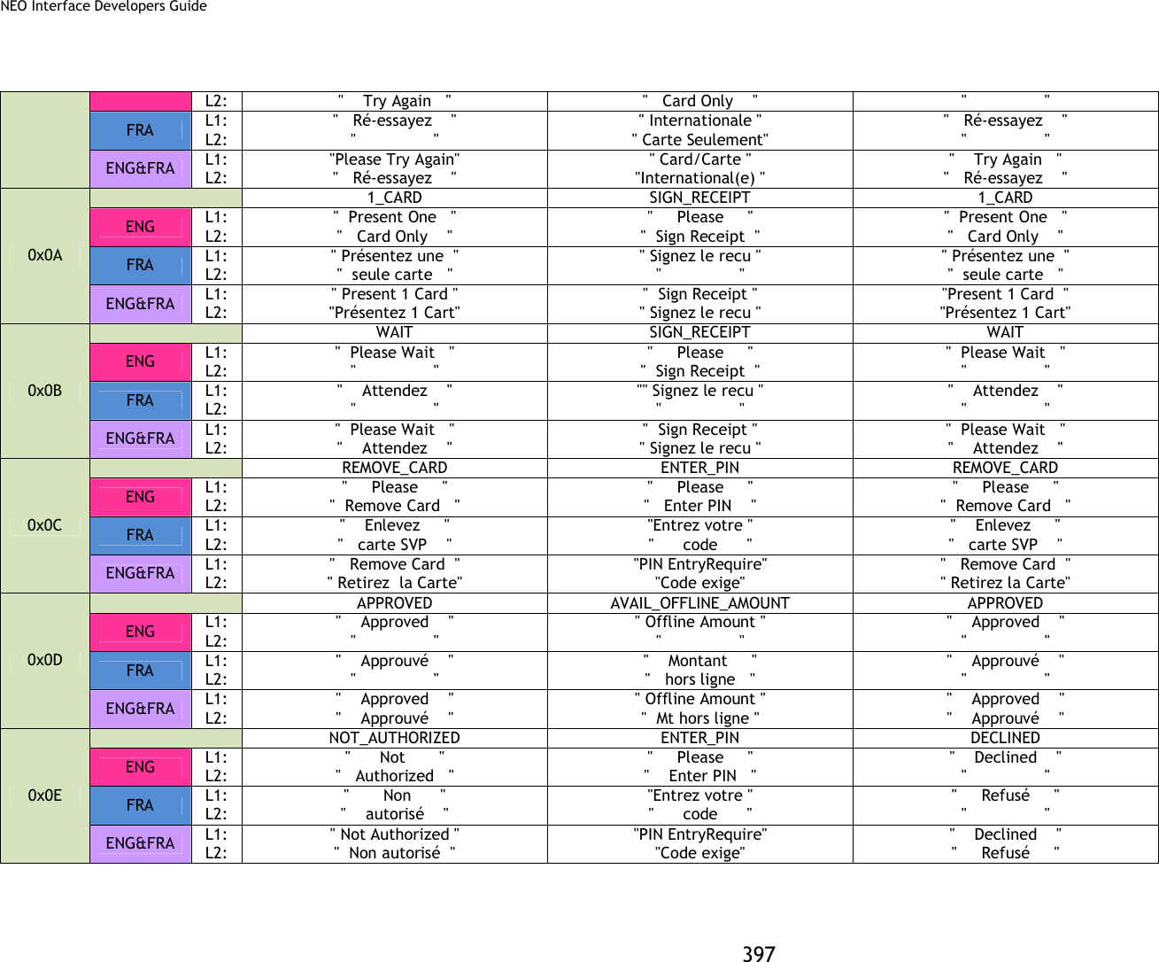
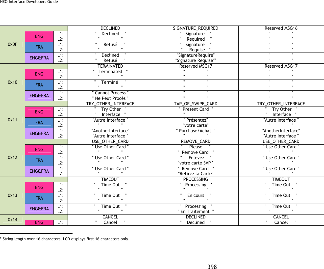
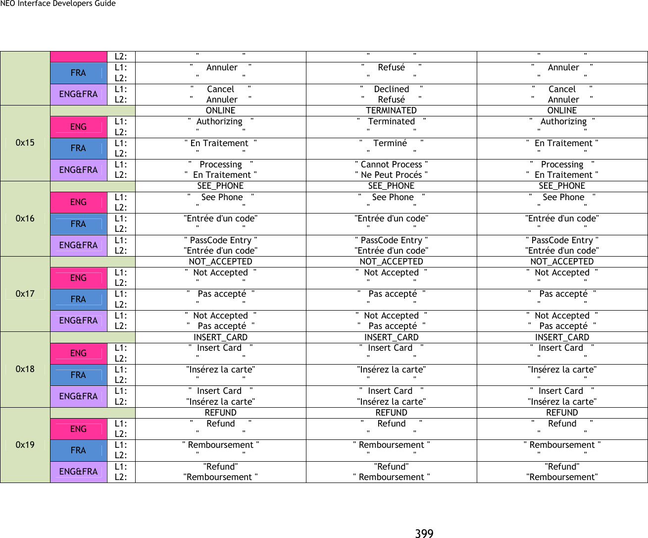
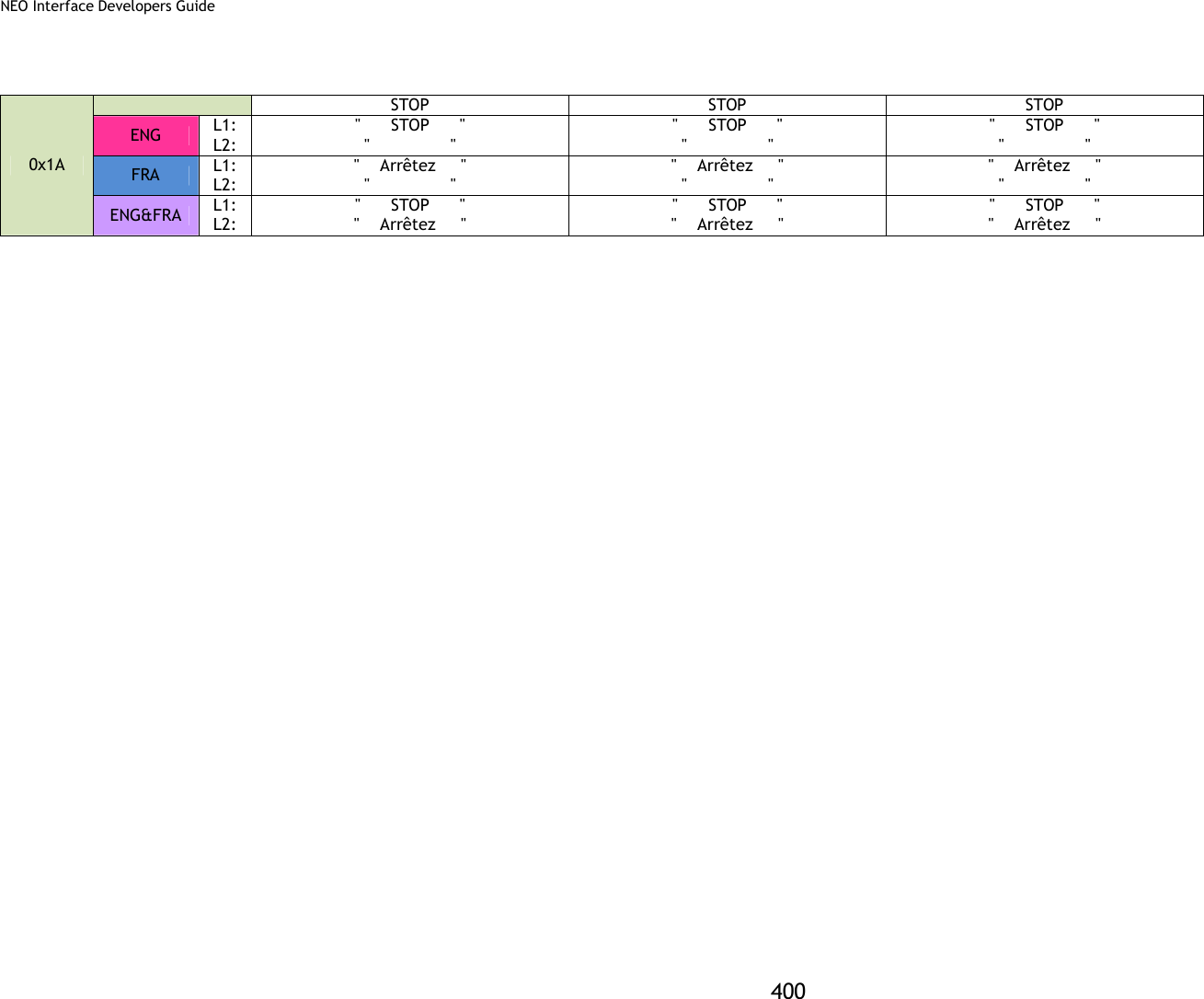
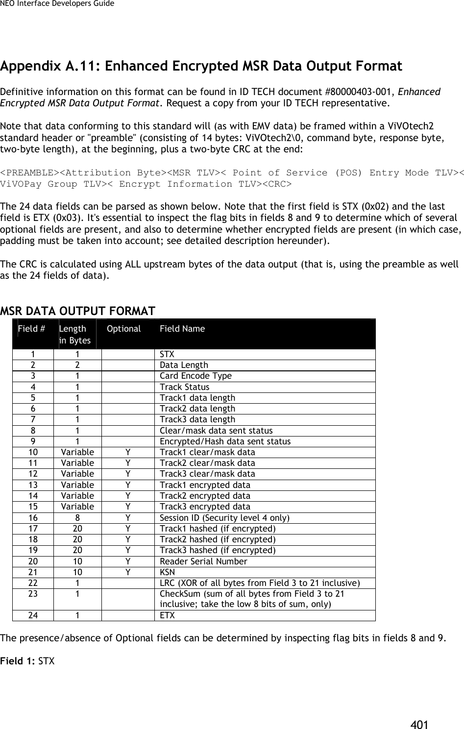
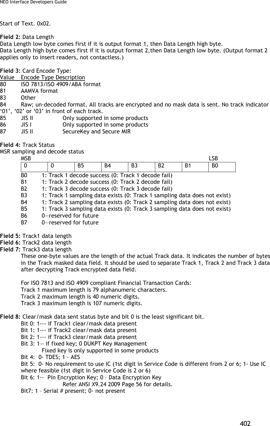
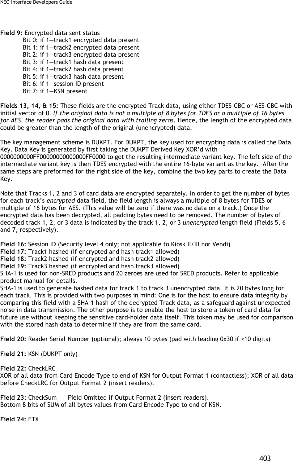

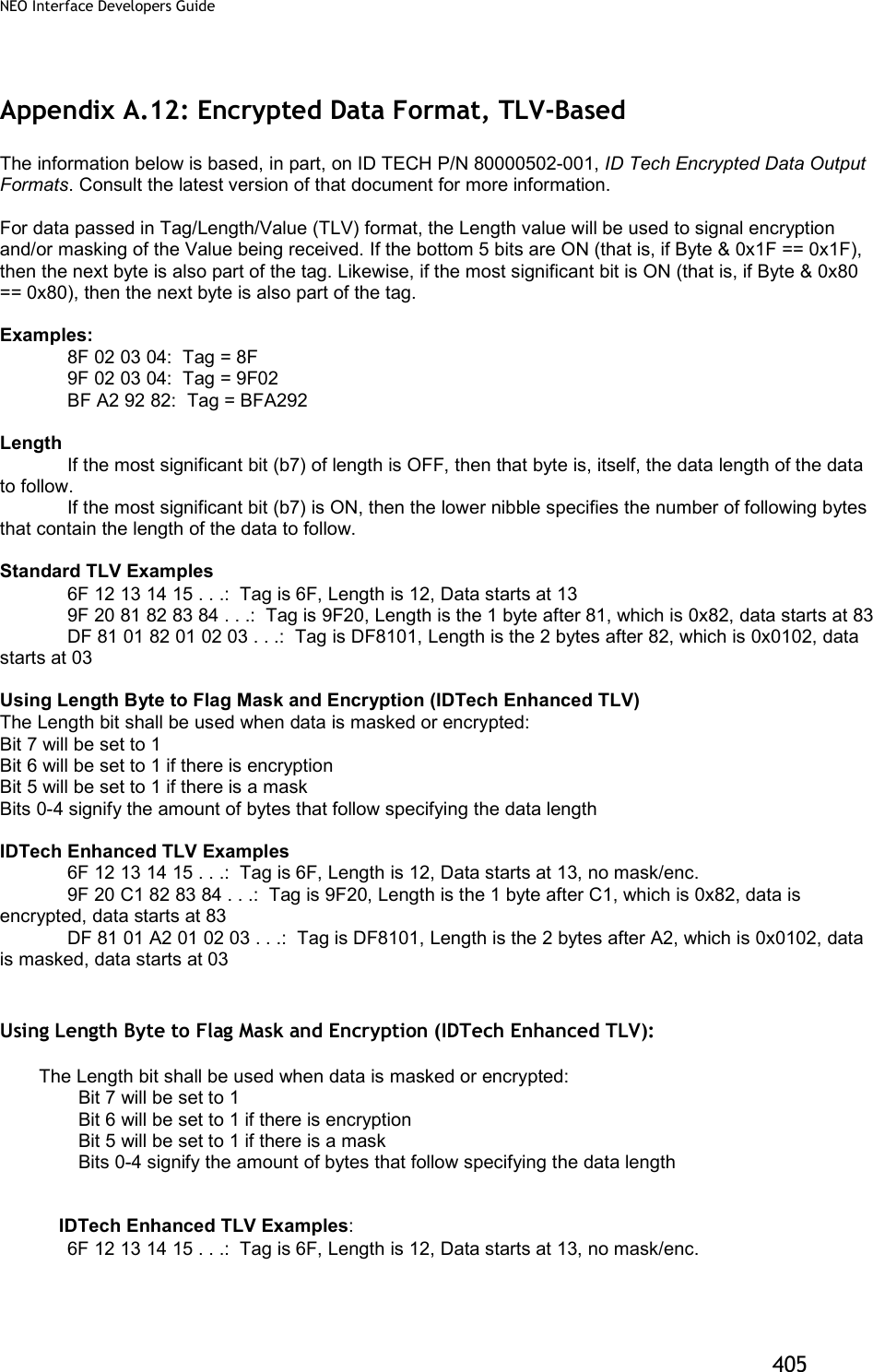
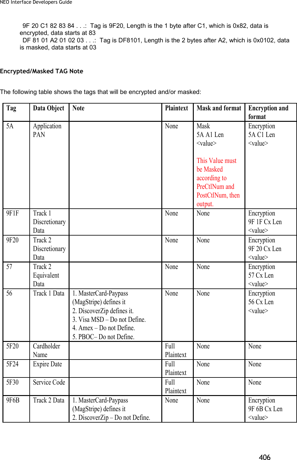
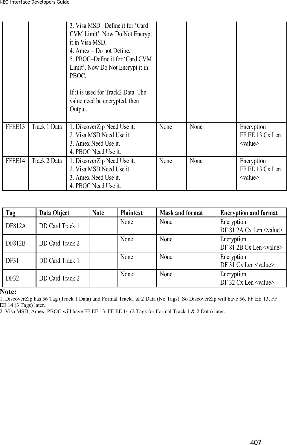
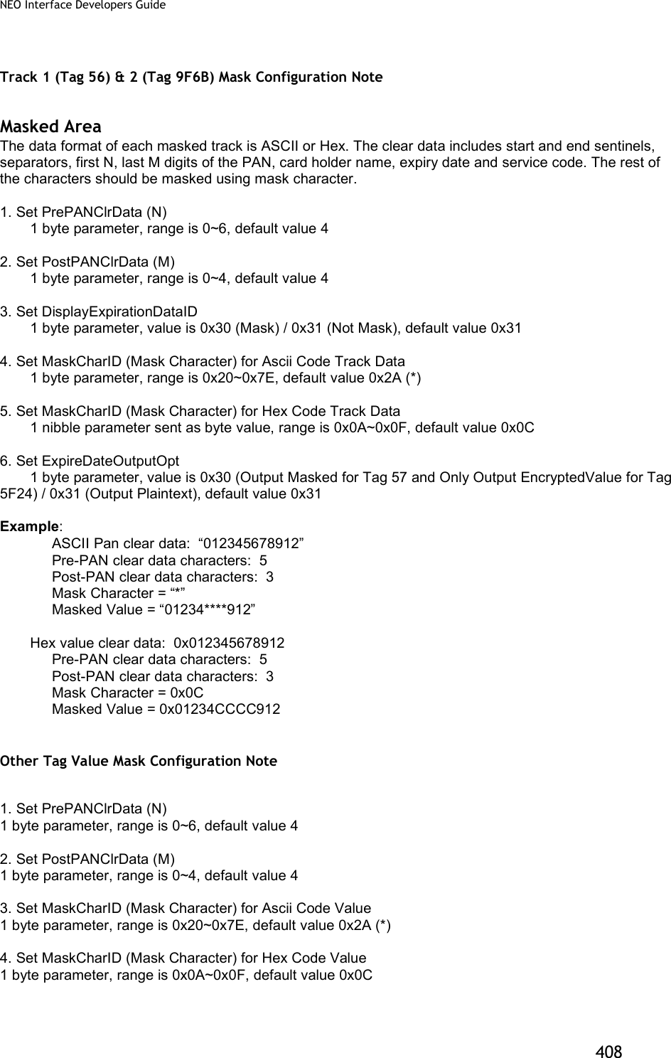
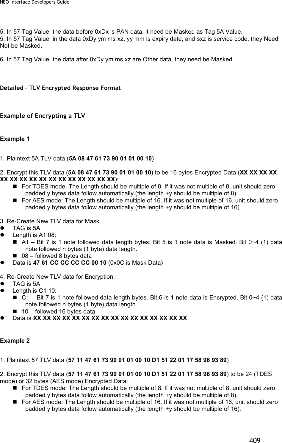
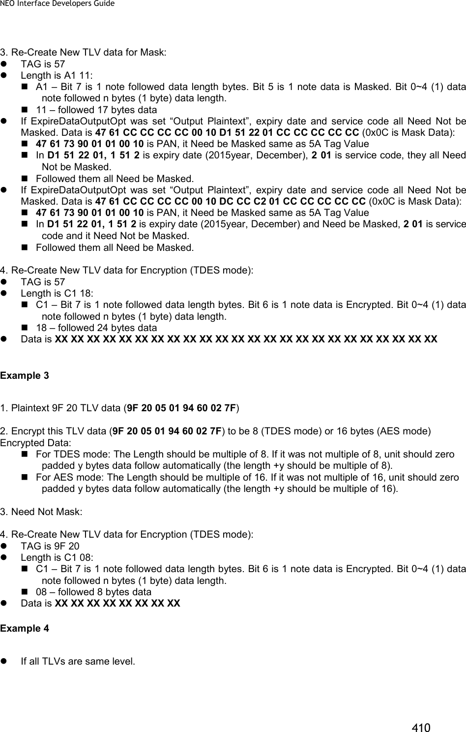
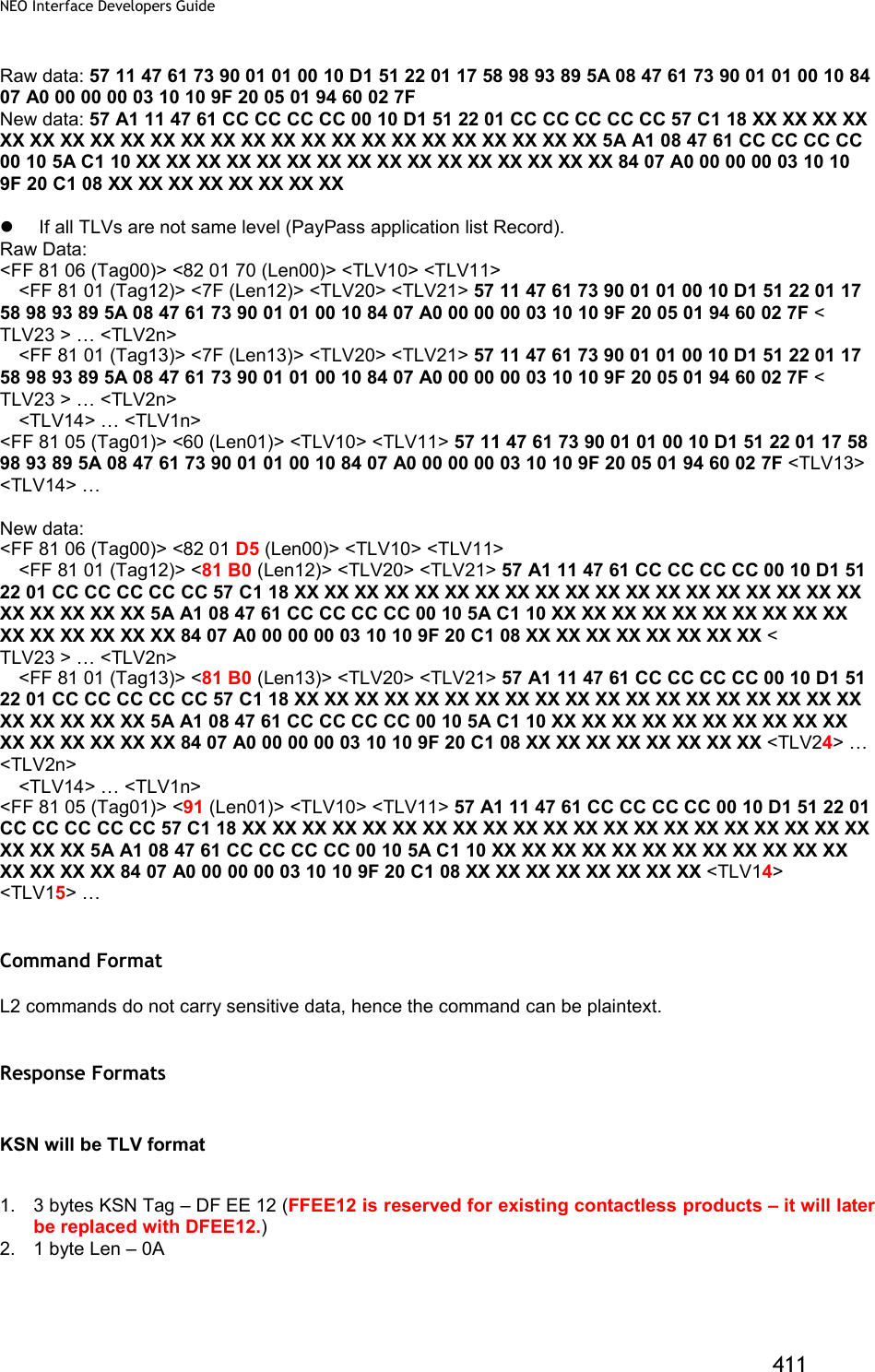
![NEO Interface Developers Guide 412 3. 10 bytes KSN Contact L2 Response Format 06 + <Transaction Result > <Attribution> [<TLV>] Where: 1. Transaction Result: 2 bytes (Approve, Decline, Other) 2. Attribution: 1 Byte BIT0 – Card Type: 0 – Contact Card BIT2,1 – Encryption Mode: 00 – TDES Mode, 01 – AES Mode BIT3 – Card Type: 0 – Contact/Contactless Card. 1 – MSR. (For ViVOpay IDG) BIT6~4 – Reserved BIT7 – Encryption Status: 0 – Encryption OFF. 1 – Encryption ON. (For ViVOpay IDG) 3. <TLV> is optional only if transaction was Approved or Declined <TLV> will include KSN as first tag (DFEE12) if new or changed since last KSN value. Encryption (bit 6) and Masking (bit5) flags will be utilized as appropriate in the Length component of the TLV element Contactless L2 Response Format 06 + <Status Code > <Error Code >< Attribution > [<TLV>] Where: 1. Status Code: 1 Byte. The usage is the same as in KioskII/KioskIII project and are used to specify if transaction was approved or declined. 2. Error Code: 1 Byte. The usage is the same as in KioskII/KioskIII project and are used to specify if transaction was approved or declined. 3. Attribution: 1 Byte BIT0 – Card Type: 1 – Contactless Card BIT2,1 – Encryption Mode: 00 – TDES Mode, 01 – AES Mode BIT3 – Card Type: 0 – Contact/Contactless Card. 1 – MSR. (For ViVOpay IDG) BIT6~4 – Reserved BIT7 – Encryption Status: 0 – Encryption OFF. 1 – Encryption ON. (For ViVOpay IDG) 4. <TLV> is optional only if transaction was Approved or Declined <TLV> will include KSN as first tag (Tag should be DFEE12, FFEE12 is reserved for existed contactless products – Later it should be replaced with DFEE12.) if new or changed since last KSN value. Encryption (bit 6) and Masking (bit5) flags will be utilized as appropriate in the Length component of the TLV element](https://usermanual.wiki/ID-TECH/VP3600/User-Guide-3704675-Page-424.png)
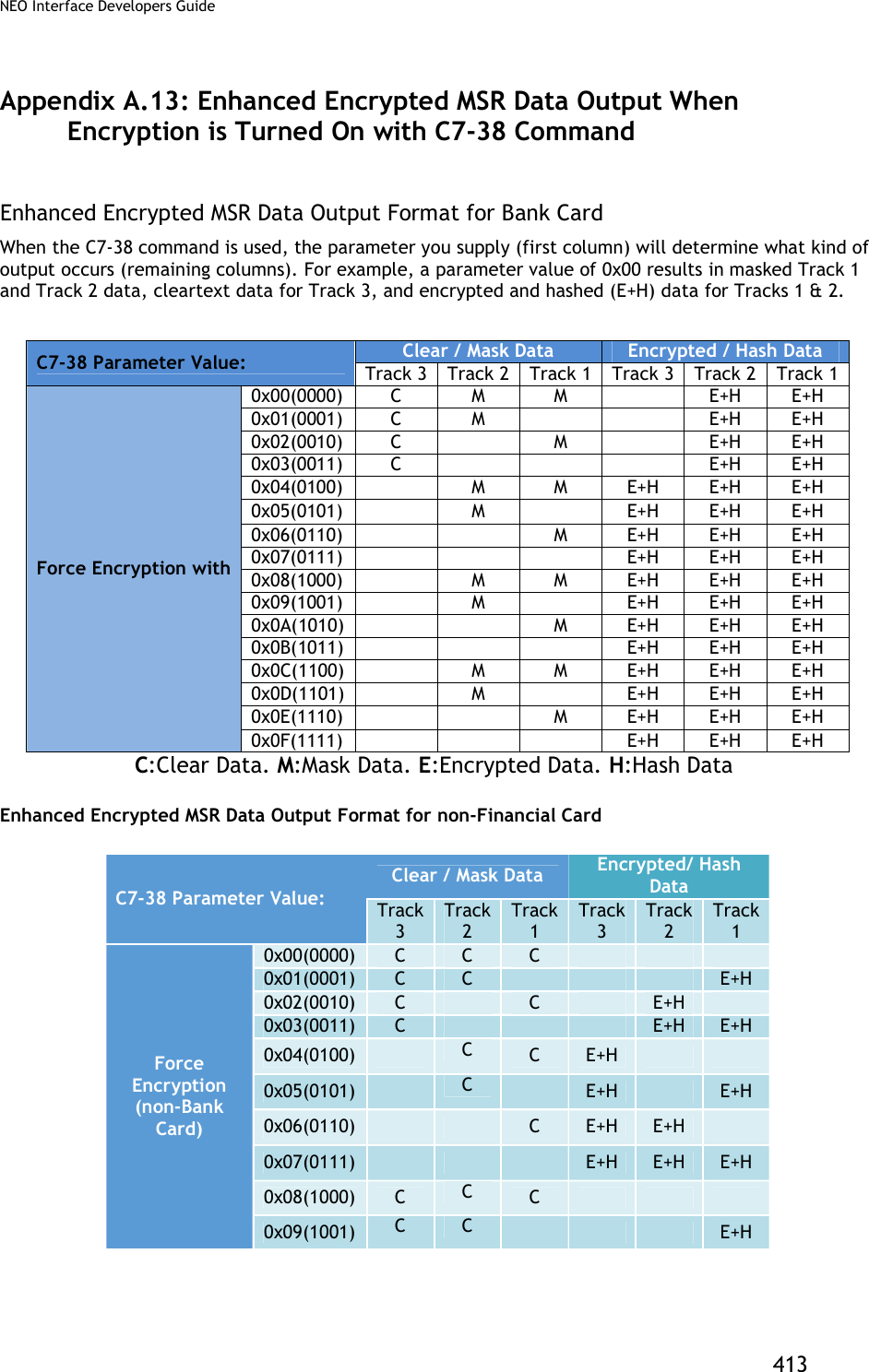
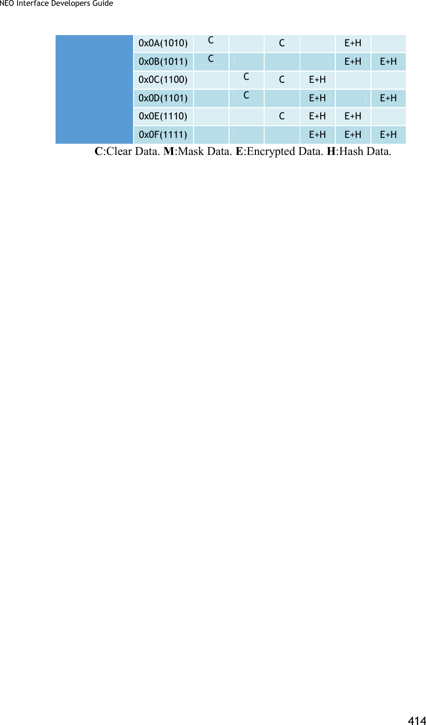
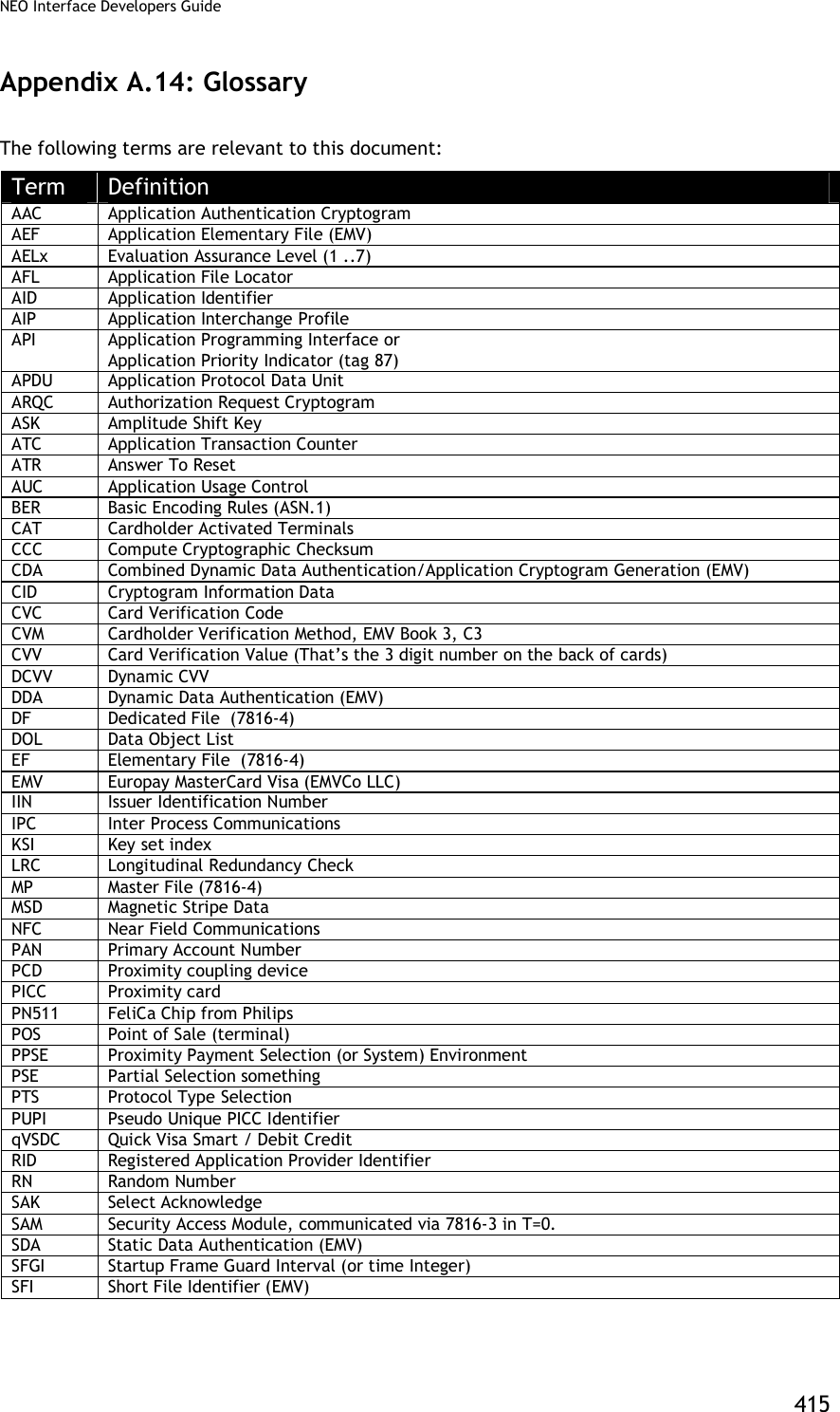
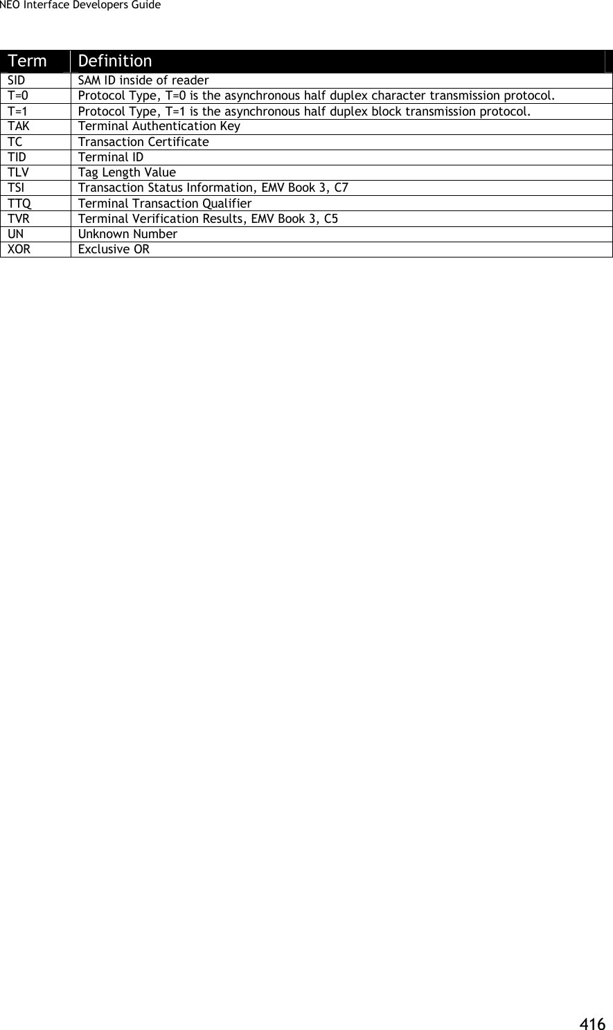
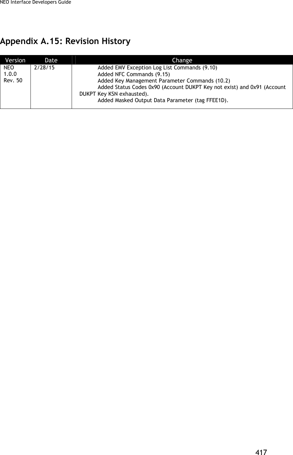
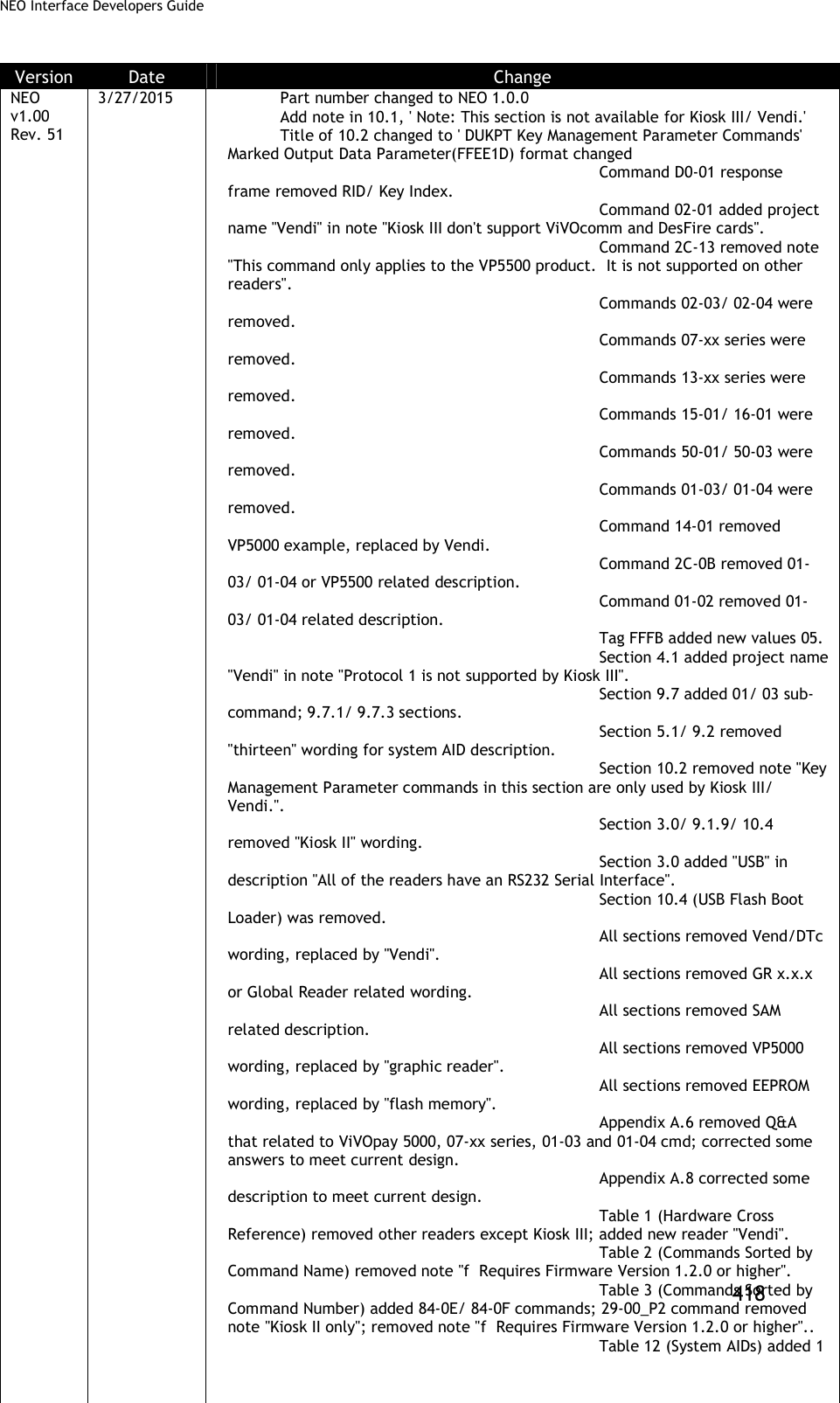
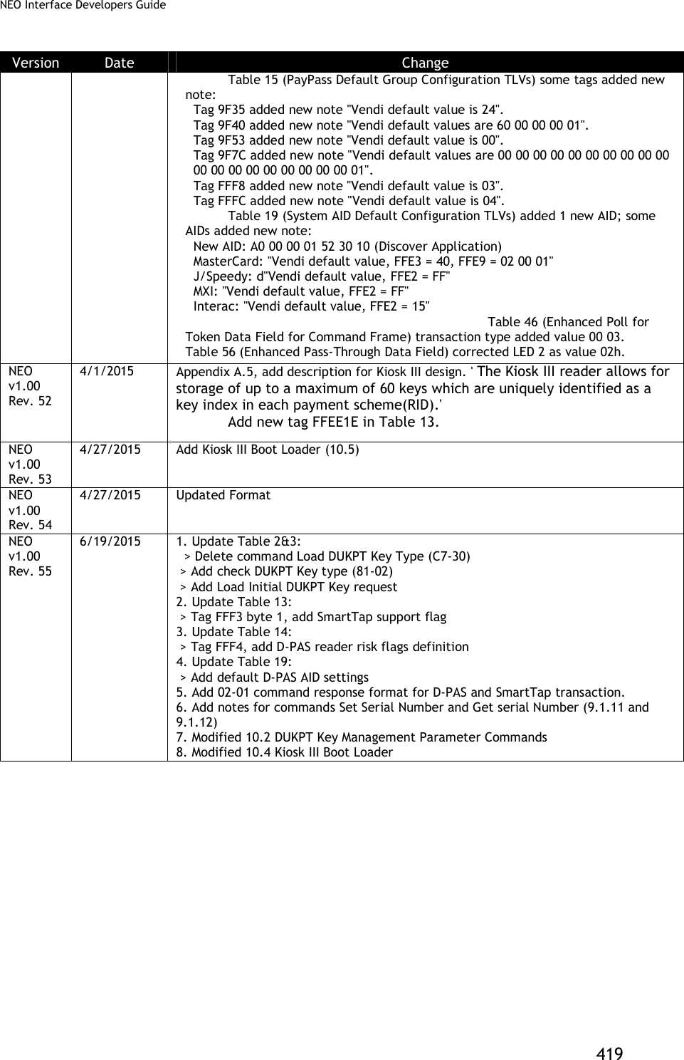
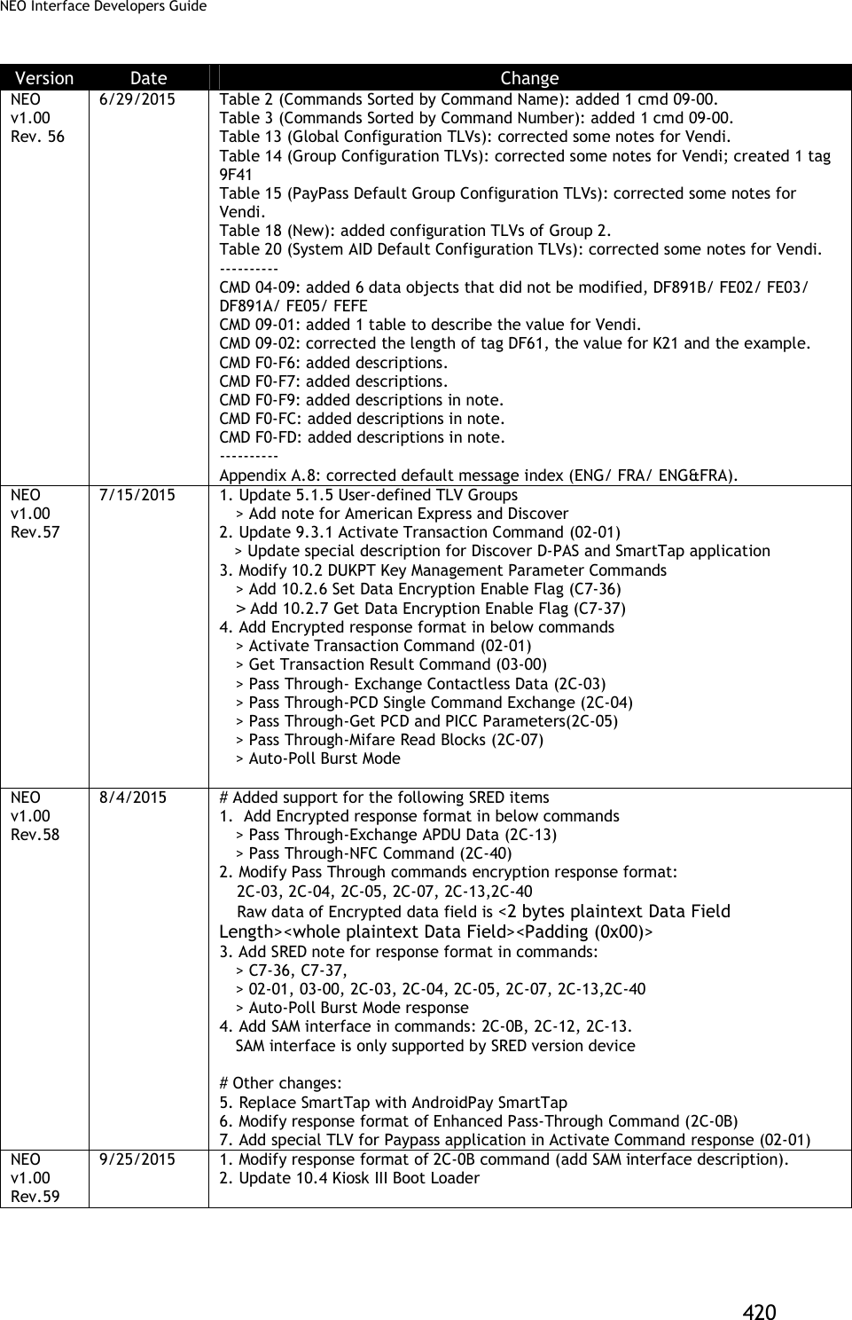
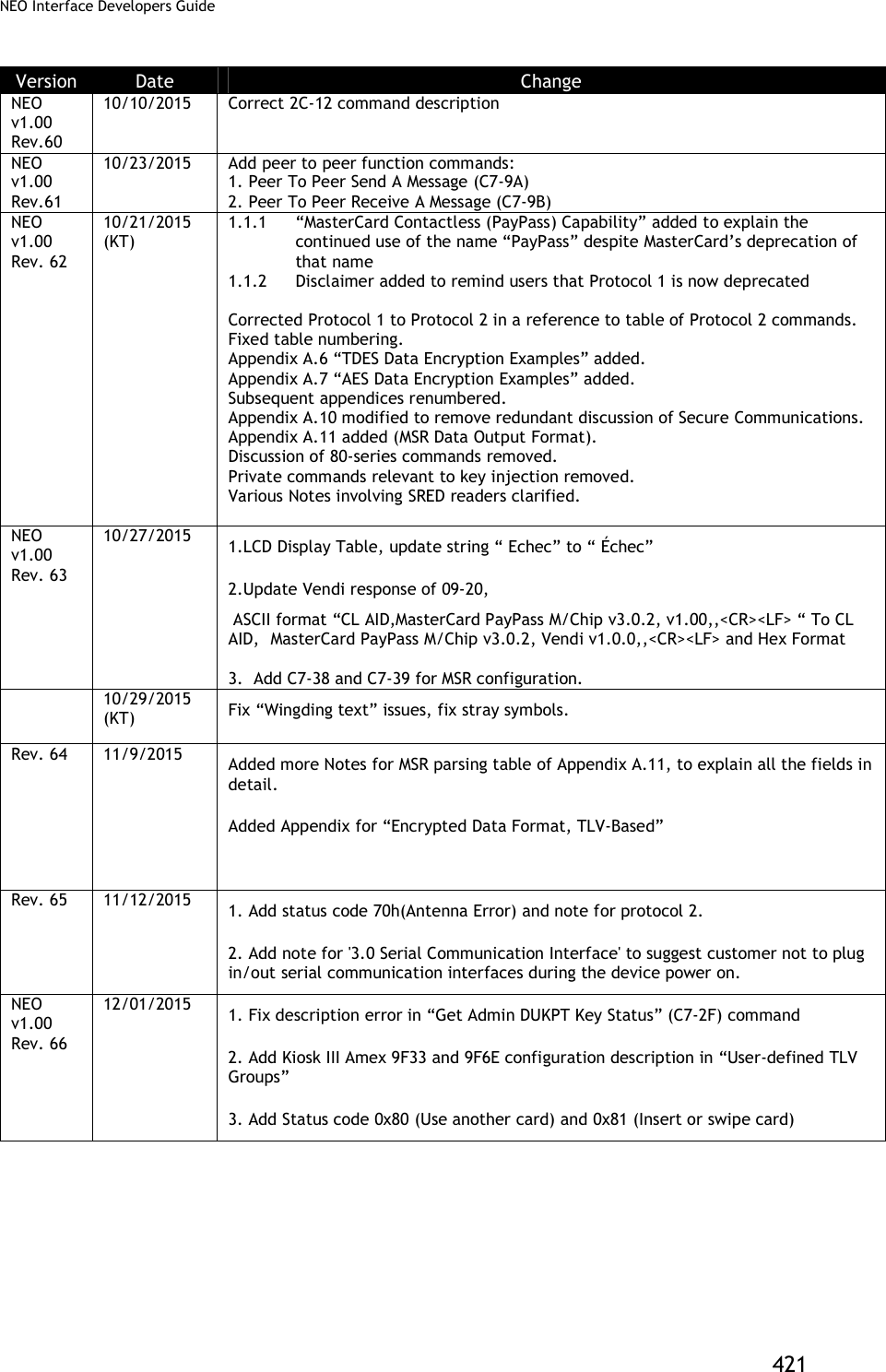
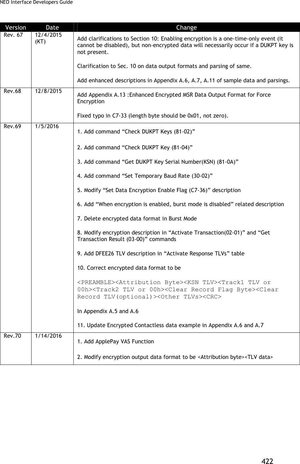
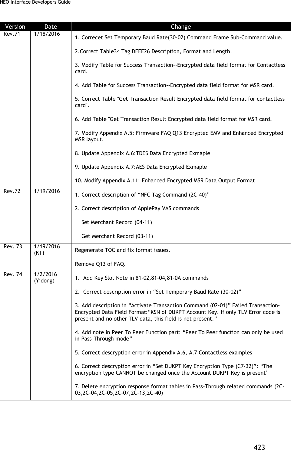
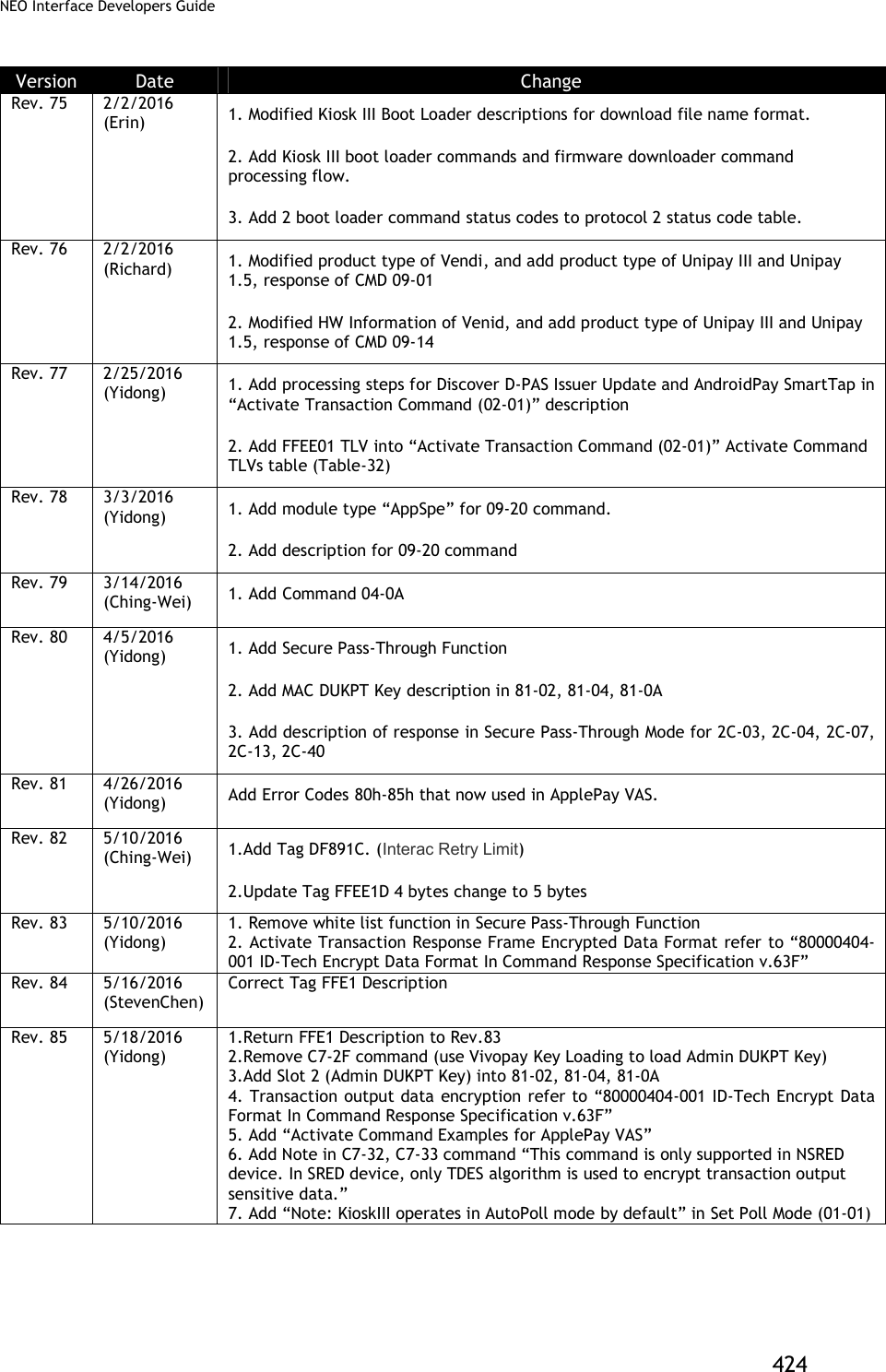
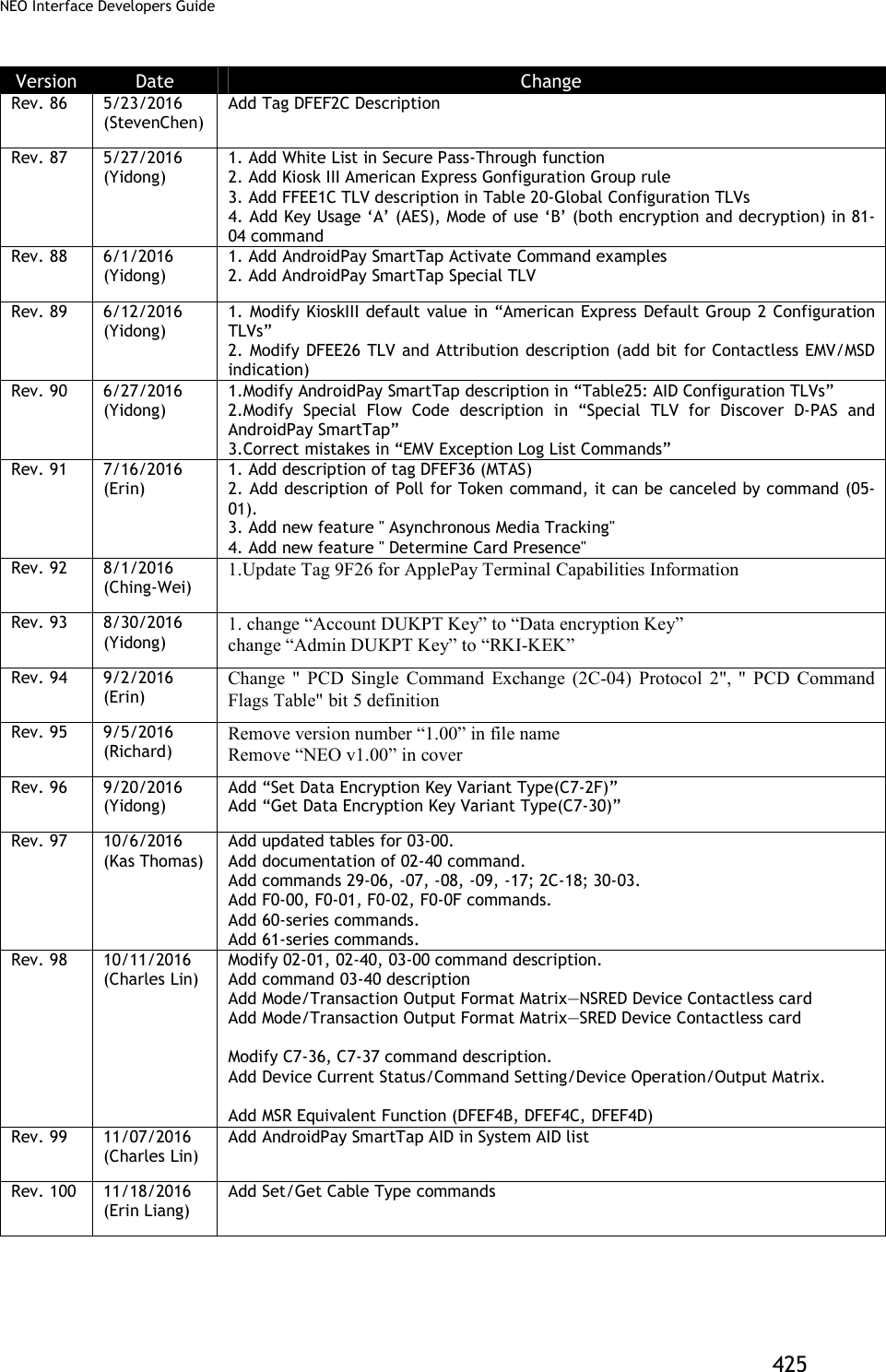
![NEO Interface Developers Guide 426 Version Date Change Rev. 101 11/28/2016 (Charles Lin) Add Note about Power LED in Set/Get Source for RTC/LCD/Buzzer/LED(01-05) command Rev. 102 01/19/2017 (Kas Thomas) ApplePay VAS discussion expanded/amplified, with additional examples (SDK methods in addition to firmware commands). Rev. 103 02/07/2017 (Erin Liang) Modify the descritpion of Clean Torn Transaction Log (84-0F) command final response format. Rev. 104 2/10/2017 (Ginger Wu) Removed the following text from page 192. “Reference files: [1] Android Pay SmartTap NFC Reader Technical Specification Version 1.3 [2] SmartTap Tester User Guide Version 0.1” Rev. 105 2/13/2017 (Kas Thomas) Added clarifications to 9F39 tag (code 07 always means contactless). Added C7-38 command info for non-financial cards in Appendix A.13 Rev. 106 02/21/2017 (Erin Liang) 1. Correct tag 57 data format in Table 35. 2. Add comments for tag DFEF4D. " The track data will present track data if it is a MSD transaction, present track Equivalent data if it is a EMV transaction." Rev. 107 02/24/2017 (Lyndon Lin) Change KSN description in Set White List (2C-50) command: “10 bytes current MAC DUKPT Key Sequence Number. Device uses current MAC DUKPT Key to do MAC verification.” Rev. 108 4/11/2017 (Kas Thomas) Correct the C7-9A and 9B peer-to-peer command description and add clarification about NDEF. Rev. 109 5/15/2017 (Erin) 1. Add CUP AIDs in System AID for Kiosk III. 2. Modify global configuration tag FFF3 from '07 FF' to '0F FF', and modify tag FFF3 definition, add CUP config. Rev. 110 6/5/2017 (ChingWei) 1.Update Tag 9F4E for contact max length 30 -> 64 2.Add Status code for protocol 2 (60, 61, 62,63) 3.Add Command 03-40 in Table 2 Rev. 111 6/13/2017 (ChingWei) Add determine ApplePay transactions tag (DFEF7A) in Active Transaction Command. Rev. 112 8/3/2017 (Erin) 1. Add Status Code 31h (Request Online PIN) for CUP. 2. Add (02-07) command for CUP 3. Add CUP TTQ default value for configurable groups 4. Add description of tag DFEF2F, DFEF73, DFEE3F, 99, 9F5B. Rev. 113 8/15/2017 Add 04-0A, F0-F4, 03-40, D0-01, and D0-02 to command tables Table 2 & 3). Rev. 114 8/25/2017 (Erin) 1. Add card type for Felica and B Prim(2c-02) 2. Add Terminate ISO Session command (2C-16) for B Prim Rev. 115 4/09/2017 (Richard) 1. Update description of tag DFEF7A that support android pay 2. add value of tag DFEF7B -> 2: android pay or android vas Rev. 116 8/09/2017 (Jiliang Ge) 1. Delete AndroidPay SmartTap1.3 support. 2. Add SmartTap2.1 support.](https://usermanual.wiki/ID-TECH/VP3600/User-Guide-3704675-Page-438.png)
![NEO Interface Developers Guide 427 CE cation RF Exposure This equipment complies with CE radiation exposure limits set forth for an uncontrolled environment.This equipment should be installed and operated with minimum distance 0cm between the radiator&your body. Specification This radio equipment operates with the following frequency bands and maximum radio-frequency power. BLE : 0dBm EU DECLARATION OF CONFORMITY Hereby, ID TECH declares that the radio equipment type [IDMR-PBTX3133TEB, X=8:VP3600; X=9:VP3500] is in compliance with Directive 2014/53/EU. The full text of the EU declaration of conformity is available at the following Internet address: http://www.idtechproducts.com](https://usermanual.wiki/ID-TECH/VP3600/User-Guide-3704675-Page-439.png)