IDENTIFICATION DEVICE TECHNOLOGY ISC-101A THE PRODUCT IS CARDREADER USING RF CARD User Manual
IDENTIFICATION DEVICE TECHNOLOGY, INC. THE PRODUCT IS CARDREADER USING RF CARD
UserManual.wiki
>
IDENTIFICATION DEVICE TECHNOLOGY
>
ISC 101A User Manual
User Manual
Navigation menu
Upload a User Manual
Namespaces
Wiki Guide
HTML
PDF
Info
Views
User Manual
Discussion / Help
Navigation
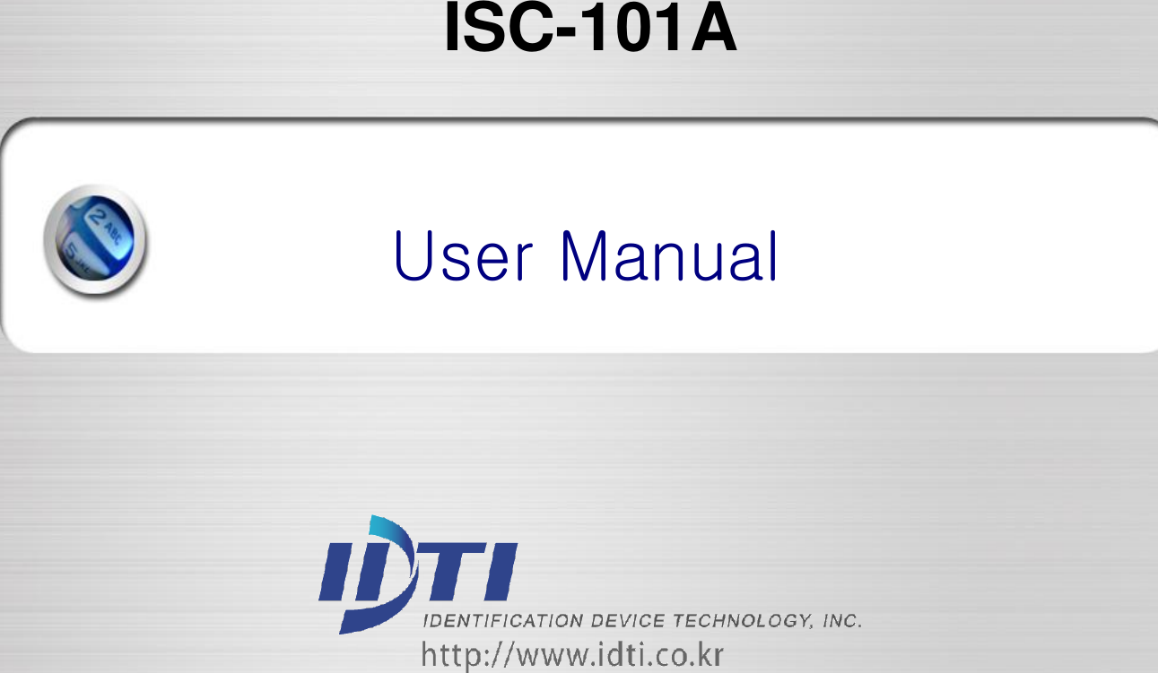
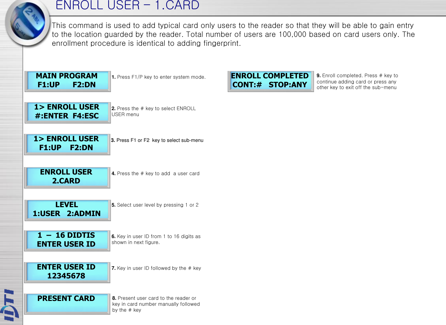
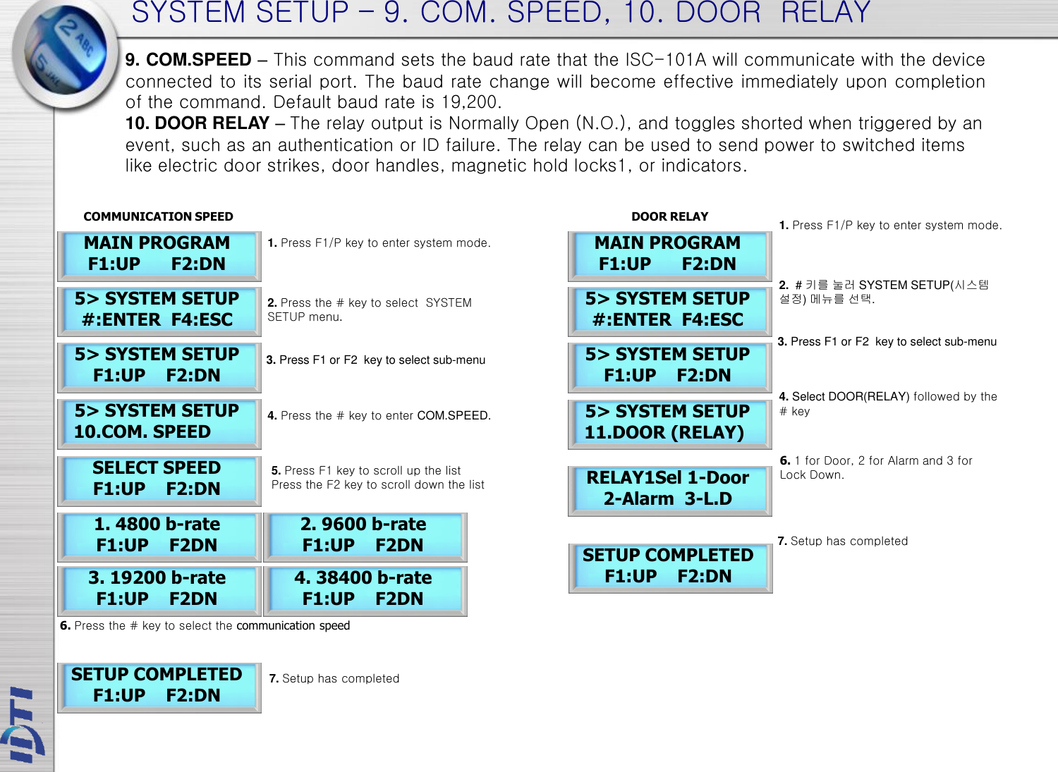
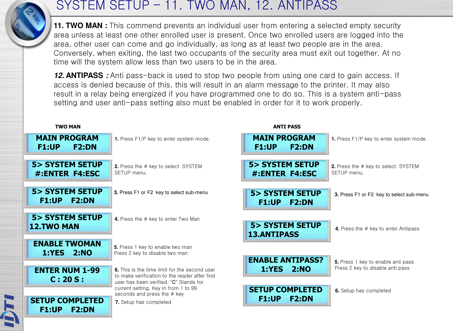
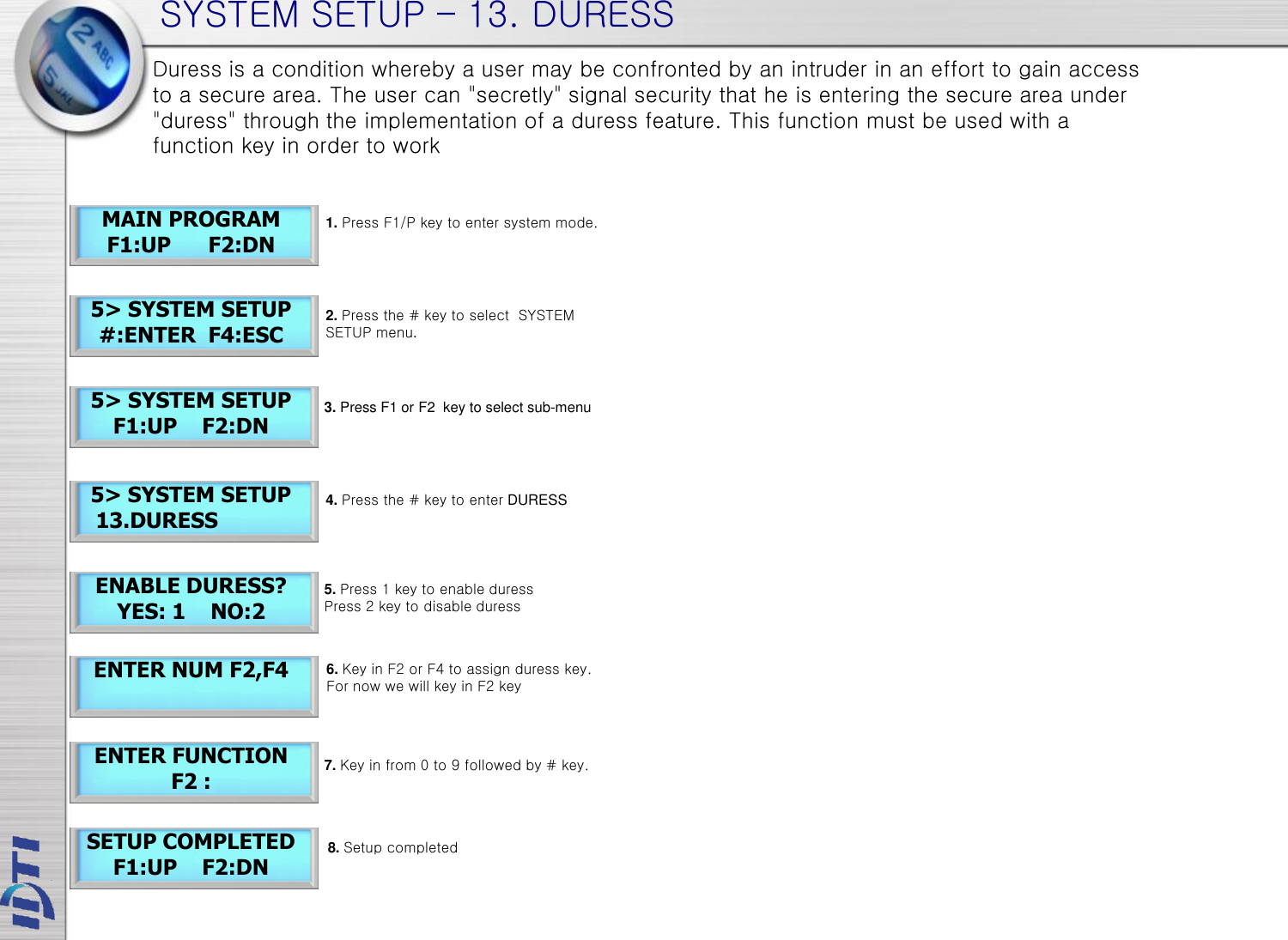
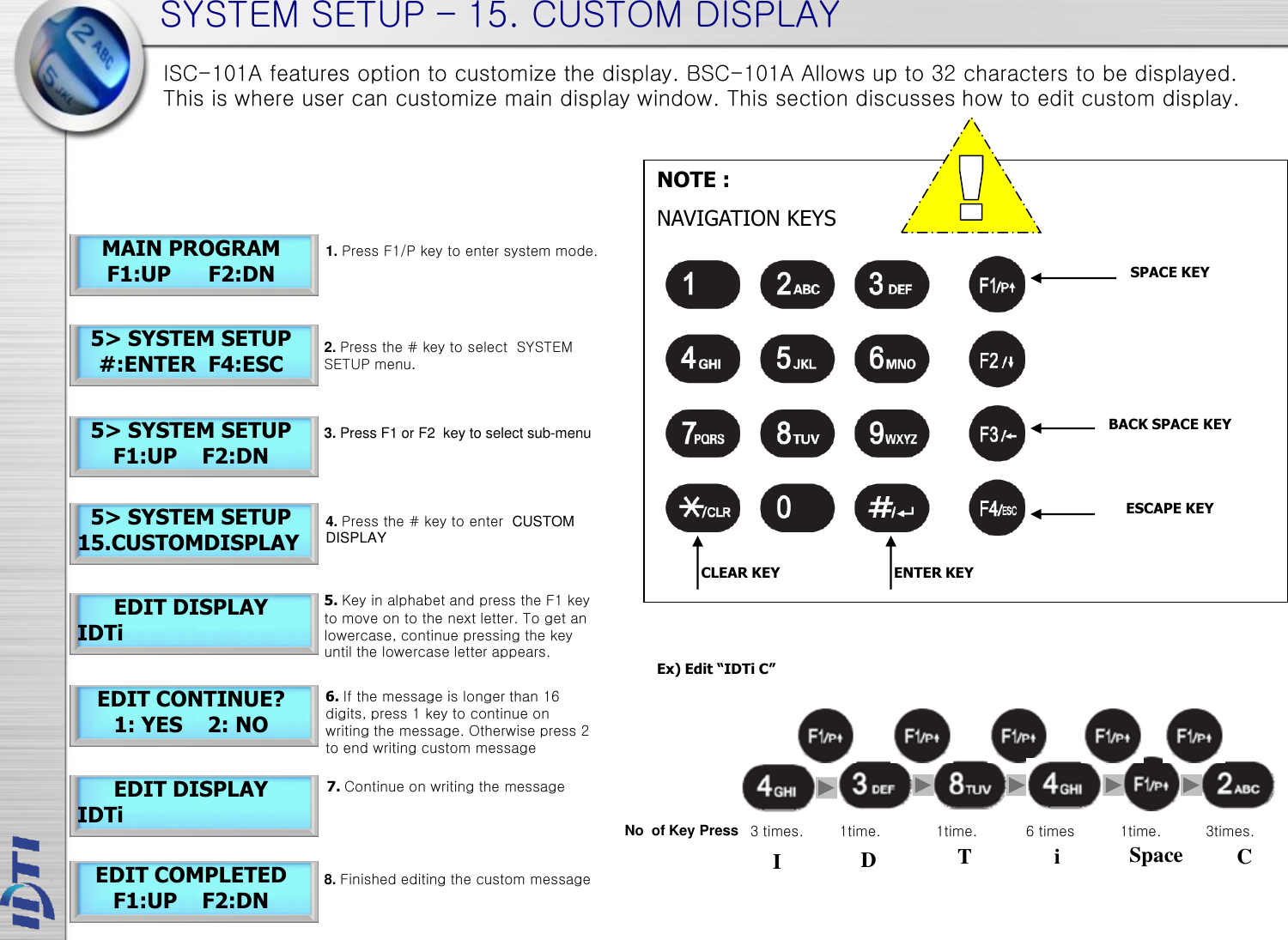
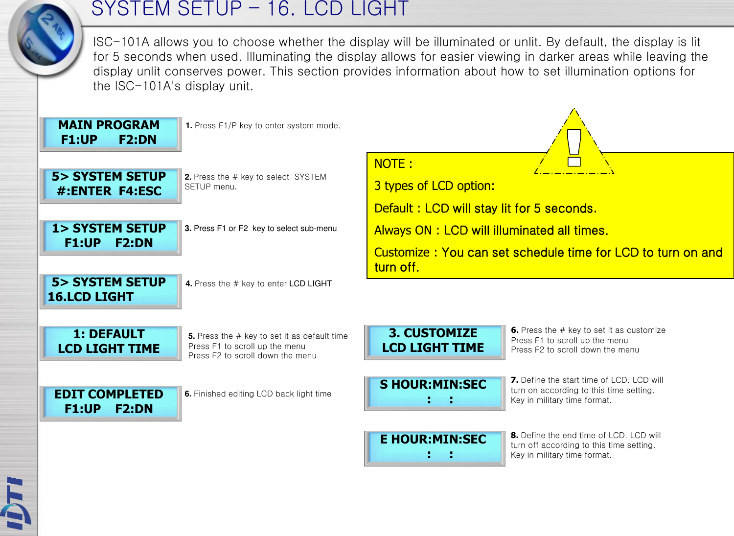
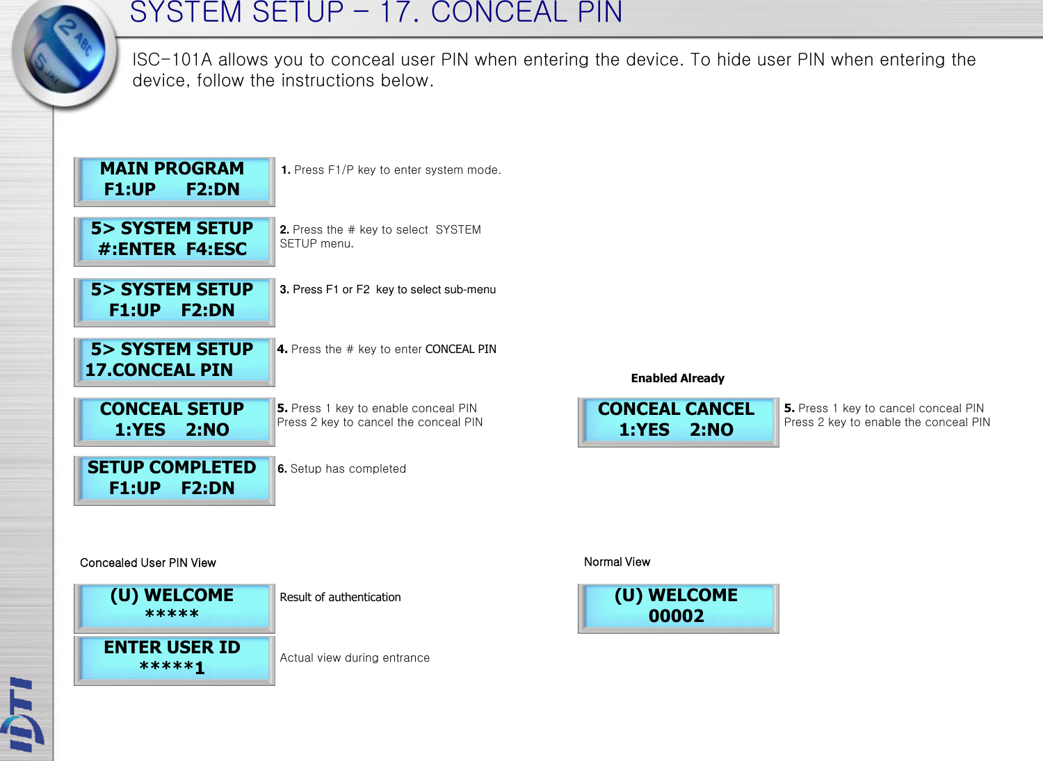
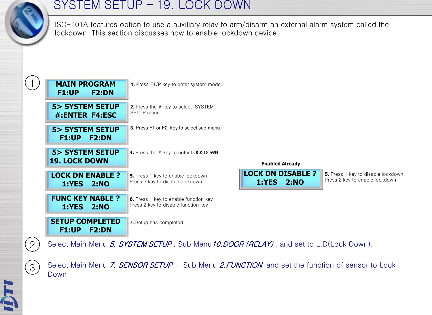
![If Administrator has been enrolled : If Administrator has been enrolled: ENTERING THE SYSTEM MENU ENTER ADMIN ID 12345678 BSC 2004.06.25 12:12:12 [FRI] MAIN PROGRAM F1:UP F2:DN BSC 2004.06.25 12:12:12 [FRI] MAIN PROGRAM F1:UP F2:DN When the reader is powered on with no user enrolled in the unit, anyone can enter the system menu by pressing the F1 key. If you are enrolling the first administrator card via the reader's keypad, you must first determine the 1~16 digit PIN that the administrator will use. Once this PIN is determined, the administrator must be present to enroll their card into the reader. Note that this operation is not valid if there are administrator card in the reader. 1. Press F1/P key to enter system mode. 2. Key in administrator ID followed by the # key 3. Present either card which ever administrator has been enrolled with. For now we will use the fingerprint. PRESENT CARD 4. Now you're into system mode. Press F1 key to scroll up the main menu Press F2 key to scroll down the main menu 1. Press F1/P key to enter system mode 2. Now you're into system mode. Press F1 key to scroll up the main menu Press F2 key to scroll down the main menu NOTE : BSC-101A factory default has no system administrator password. If you've just purchased the unit, you should be able to get into the system mode by pressing the F1 key. Go to ENROLL USER to enroll template or card. 1> ENROLL USER #:ENTER F4:ESC Lists of Main Menu 2> EDIT USER #:ENTER F4:ESC 3> VIEW #:ENTER F4:ESC 4> DELETE #:ENTER F4:ESC 5> SYSTEM SETUP #:ENTER F4:ESC 6> SENSOR SETUP #:ENTER F4:ESC 7> ALARM SETUP #:ENTER F4:ESC 1. Press F1/P key to enter system mode. 2. Press F1 key to scroll up, F2 key to scroll down the main menu](https://usermanual.wiki/IDENTIFICATION-DEVICE-TECHNOLOGY/ISC-101A/User-Guide-2170685-Page-9.png)
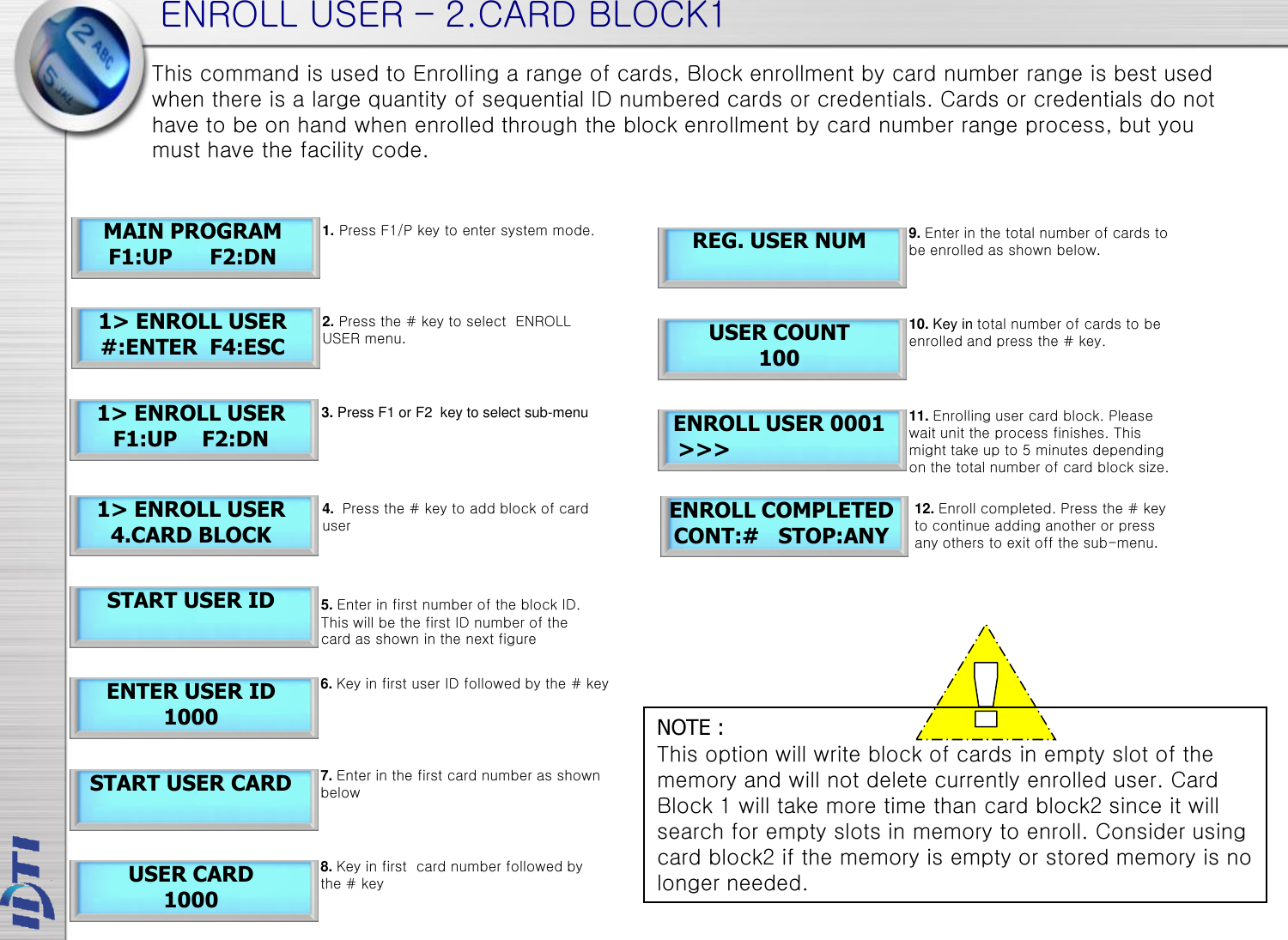


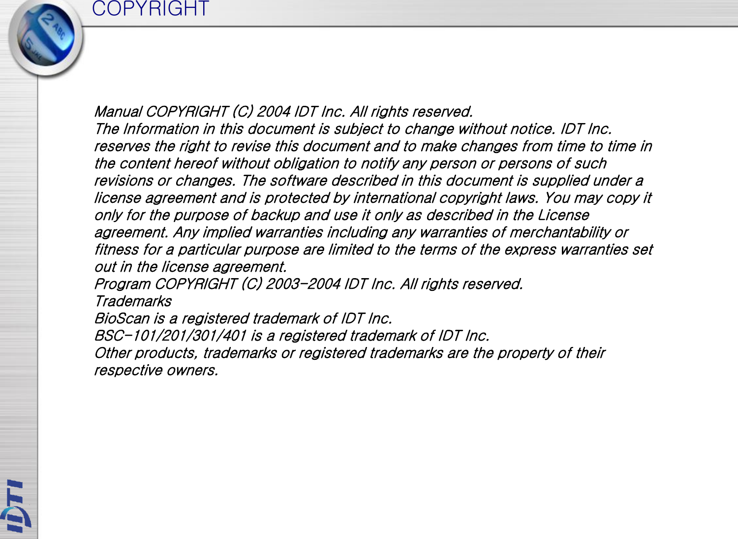
![SYSTEM SETUP – 1.TIME 5> SYSTEM SETUP 1.TIME YEAR:MON:DAY 2004 : 07 : 05 HOUR:MIN:SEC 20 : 20 : 20 1:SUN .. 7:SAT SELECT 1-7 MAIN PROGRAM F1:UP F2:DN 5> SYSTEM SETUP #:ENTER F4:ESC 5> SYSTEM SETUP F1:UP F2:DN 1:SUN ..7:SAT [FRI] ENTER ‘#’ SETUP SOMPLETED F1:UP F2:DN ISC-101A features an internal clock that provides the date and time for all logged events. This section discusses how to set the date and time that ISC-101A uses for event logging. To set the current time, access the menu system and follow these steps. NOTE : Time format can be displayed in 3 types. Asian Time, European Time and American Time. After setting the current time, go to page and customized the time display option to view local time display. Select the day of week: Sunday – 1 Monday – 2 Tuesday – 3 Wednesday – 4 Thursday – 5 Friday – 6 Saturday – 7 CLEAR KEY ENTER KEY ESCAPE KEY BACK SPACE KEY 1. Press F1/P key to enter system mode. 2 Press the # key to select SYSTEM SETUP menu. 4. Press the # key to enter system Time 5. Enter current date followed by the # key 6. Enter current time followed by the # key 3. Press F1 or F2 key to select sub-menu 9. Set up has completed 7. Select day of the week. Press 1 through 7 to enter day of the week. Refer to NOTE 8. Press the # key to confirm.](https://usermanual.wiki/IDENTIFICATION-DEVICE-TECHNOLOGY/ISC-101A/User-Guide-2170685-Page-29.png)
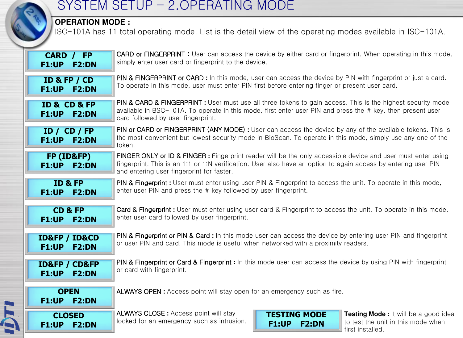
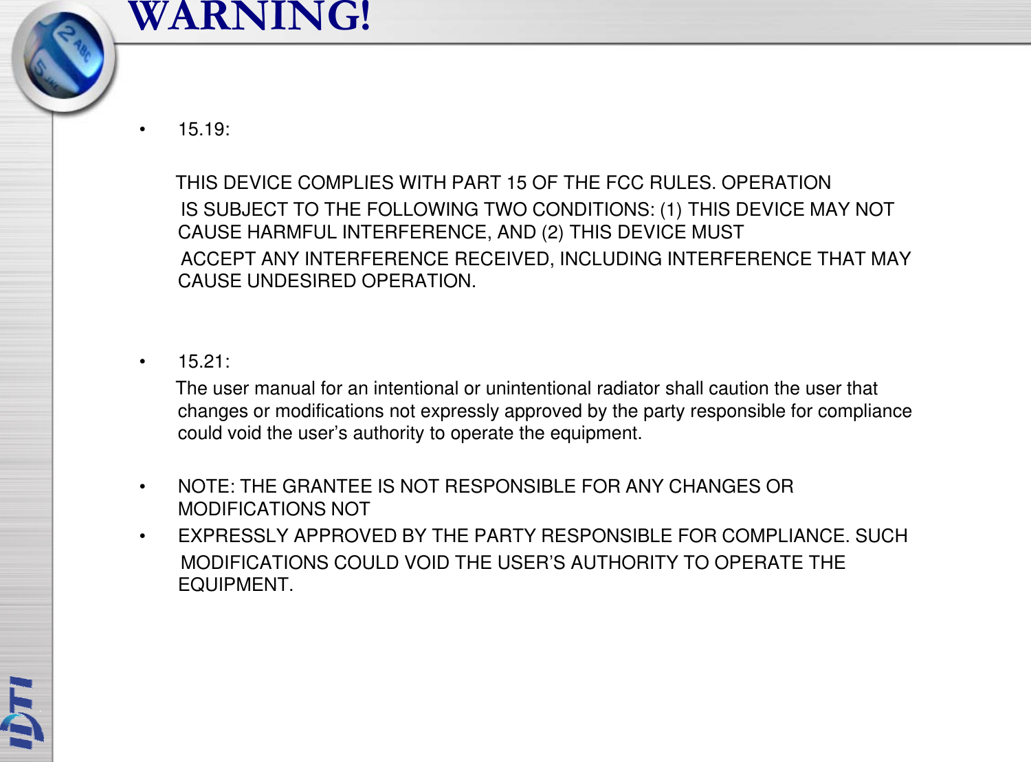
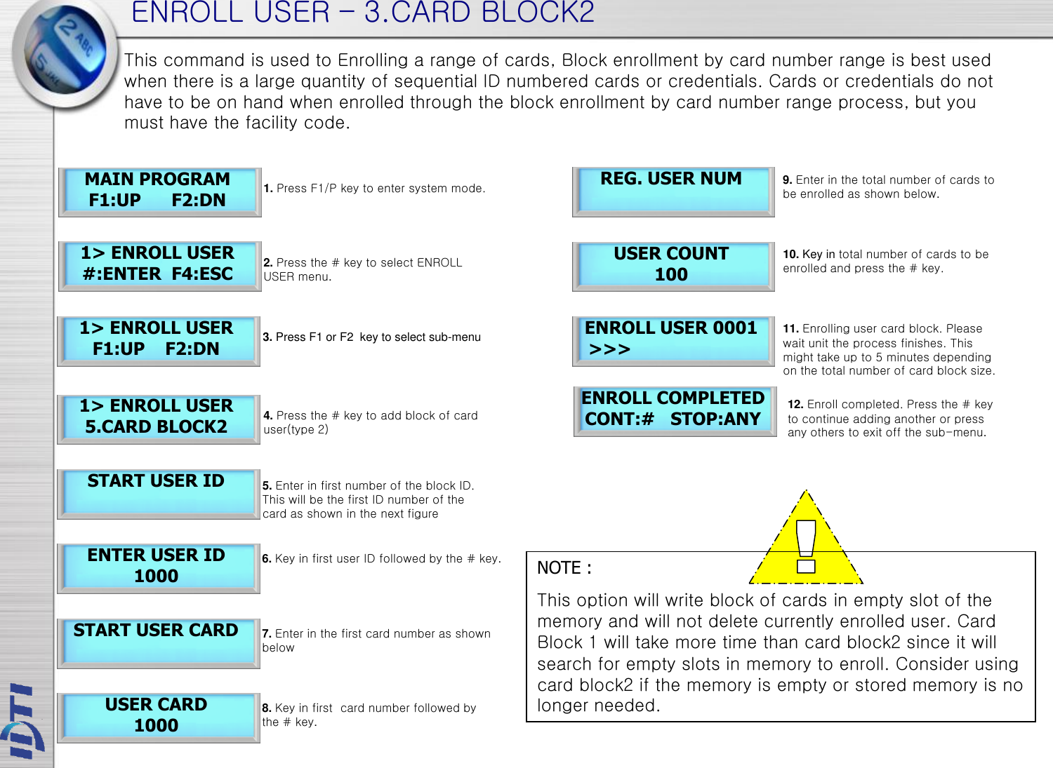
![SYSTEM SETUP – 2.OPERATING MODE 5> SYSTEM SETUP 2.OPERATING MODE SELECT MODE F1:UP F2:DN [CD] [FP] F1:UP F2:DN SETUP COMPLETED F1:UP F2:DN This section provides information about how to choose the operation mode. ID/CD/FP (ALL) is the default operating mode. SELECT MODE F1:UP F2:DN List of operating modes to choose. Select from the following list. MAIN PROGRAM F1:UP F2:DN 5> SYSTEM SETUP #:ENTER F4:ESC 5> SYSTEM SETUP F1:UP F2:DN 1. Press F1/P key to enter system mode. 2. Press the # key to select SYSTEM SETUP menu. 4. Select OPERATING MODE followed by the # key 5. Press F1 key to scroll up the mode menu Press F2 key to scroll down the mode menu 6. Press the # key to select operating mode. 3. Press F1 or F2 key to select sub-menu 7. Setup completed OPEN F1:UP F2:DN CARD / FP F1:UP F2:DN ID & FP / CD F1:UP F2:DN CLOSED F1:UP F2:DN ID&FP / ID&CD F1:UP F2:DN ID / CD / FP F1:UP F2:DN TESTING MODE F1:UP F2:DN](https://usermanual.wiki/IDENTIFICATION-DEVICE-TECHNOLOGY/ISC-101A/User-Guide-2170685-Page-31.png)
![SYSTEM SETUP – 14. DATE FORMAT 5> SYSTEM SETUP 14.DATE FORMAT SELECT DISPLAY F1:UP F2:DN MAIN PROGRAM F1:UP F2:DN 5> SYSTEM SETUP #:ENTER F4:ESC 5> SYSTEM SETUP F1:UP F2:DN 1: ASIA YYYY.MM.DD EDIT COMPLETED F1:UP F2:DN 2: USA MM.DD.YYYY 3: EUROPE DD.MM.YYYY 4: CUSTOM1 Message DD/MM 5: CUSTOM1 Message MM/DD NOTE : BSC 2004.09.09 17:50:30 [THU] BSC 08.30.2004 12:30:30 [THU] BSC 30.08.2004 12:30:30 [THU] IDTi 12:30:30 30/08 IDTi 12:30:30 08/30 ASIA Time display format USA Time display format EUROPE Time display format CUSTOM 1 Time display format with Europe date format. Date is displayed before the month CUSTOM 2 Time display format with American date format. Month is displayed before the date ISC-101A features option to choose time format which are available in Asia time, USA time, and Europe time. This is where user can customize time format. This section discusses how to choose time format. 1. Press F1/P key to enter system mode. 2. Press the # key to select SYSTEM SETUP menu. 4. Press the # key to enter DATE FORMAT 3. Press F1 or F2 key to select sub-menu 5. Press F1 key to scroll up the list Press F2 key to scroll down the list 6. Select the right time format for your region 7. Time format has been set](https://usermanual.wiki/IDENTIFICATION-DEVICE-TECHNOLOGY/ISC-101A/User-Guide-2170685-Page-38.png)
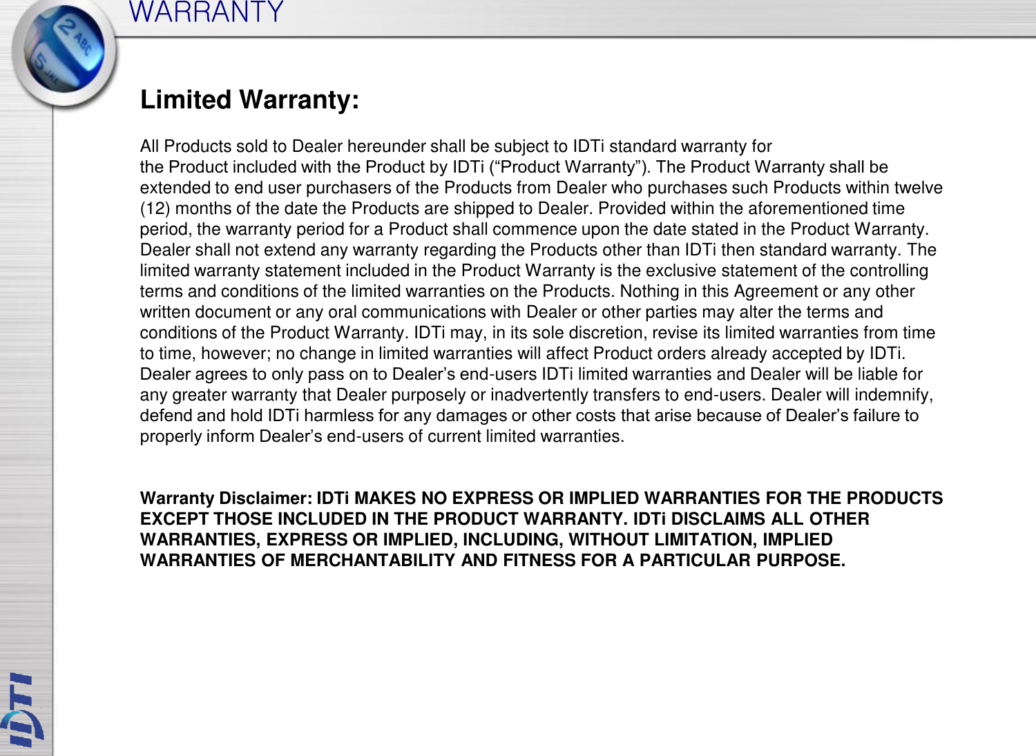
![SYSTEM SETUP – 20. ATTENDENCE 5> SYSTEM SETUP 20.ATTENDENCE ATTENDENCE SETUP 1:YES 2:NO SETUP COMPLETED F1:UP F2:DN 5> SYSTEM SETUP F1:UP F2:DN 5. Press 1 to setup attendance Press 2 to cancel setup 4. Press the # key to enter ATTENDENCE IN 2005.12.27 16:17:59 [TUE] MAIN PROGRAM F1:UP F2:DN 5> SYSTEM SETUP #:ENTER F4:ESC 1. Press F1/P key to enter system mode. 2. Press the # key to select SYSTEM SETUP menu. 3. Press F1 or F2 key to select sub-menu 6. Setup has completed ISC-101A features option to display IN or OUT when function keys are used. User must be aware of the current attendance mode that is displayed in the standby display. Last used attendance mode will be the default mode until the next mode is used. If F2-0 is used the last time, then unless second user uses a different function key, it will show as F2-0 even if second user do not press any function key. OUT 2005.12.27 16:17:59 [TUE] E-IN 2005.12.27 16:17:59 [TUE] E-OUT 2005.12.27 16:17:59 [TUE] F2-0 F4-0 F2-1 F2-2 ATTEND LEAVE RETURN OUT (U) < I N > F2:0 123456 (U) < O U T > F4:0 123456 (U) < EX-IN> F2:1 123456 (U) < EX-OUT F2:2 123456 F2-0 F4-0 F2-1 F2-2 ATTEND OUT RETURN OUT Standby LCD Display Access Granted Display](https://usermanual.wiki/IDENTIFICATION-DEVICE-TECHNOLOGY/ISC-101A/User-Guide-2170685-Page-43.png)