IQ mobil solutions TIRU Wireless Data Monitor User Manual TEMPRIS
IQ-mobil solutions GmbH Wireless Data Monitor TEMPRIS
UserManual.wiki
>
IQ mobil solutions
>
TIRU User Manual
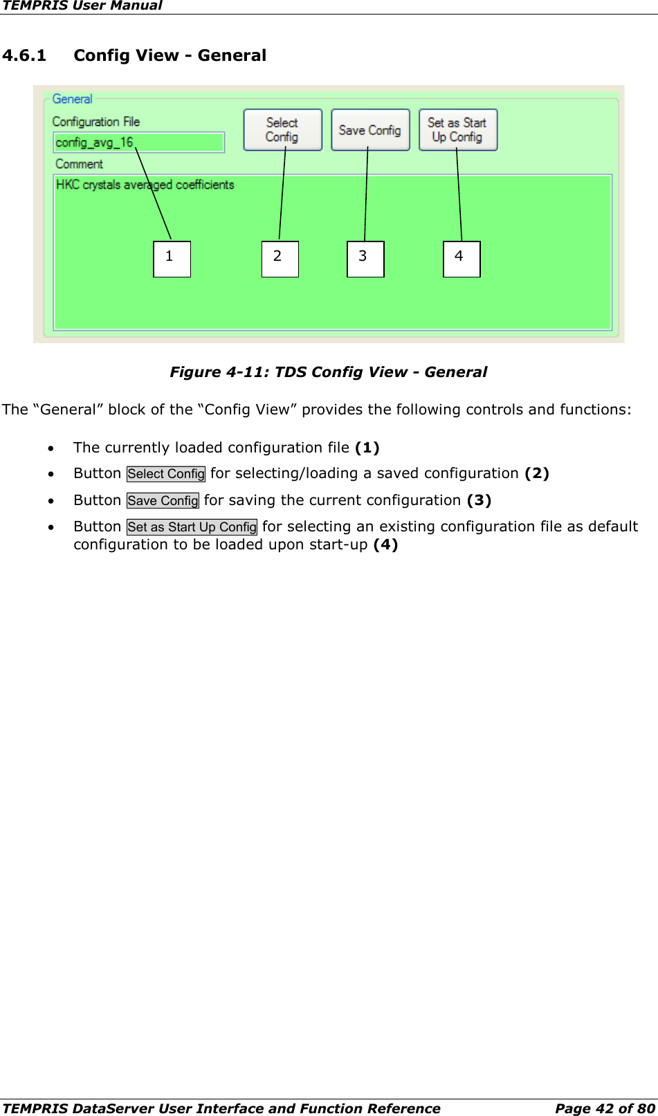
User Manual
Navigation menu
Upload a User Manual
Namespaces
Wiki Guide
HTML
PDF
Info
Views
User Manual
Discussion / Help
Navigation
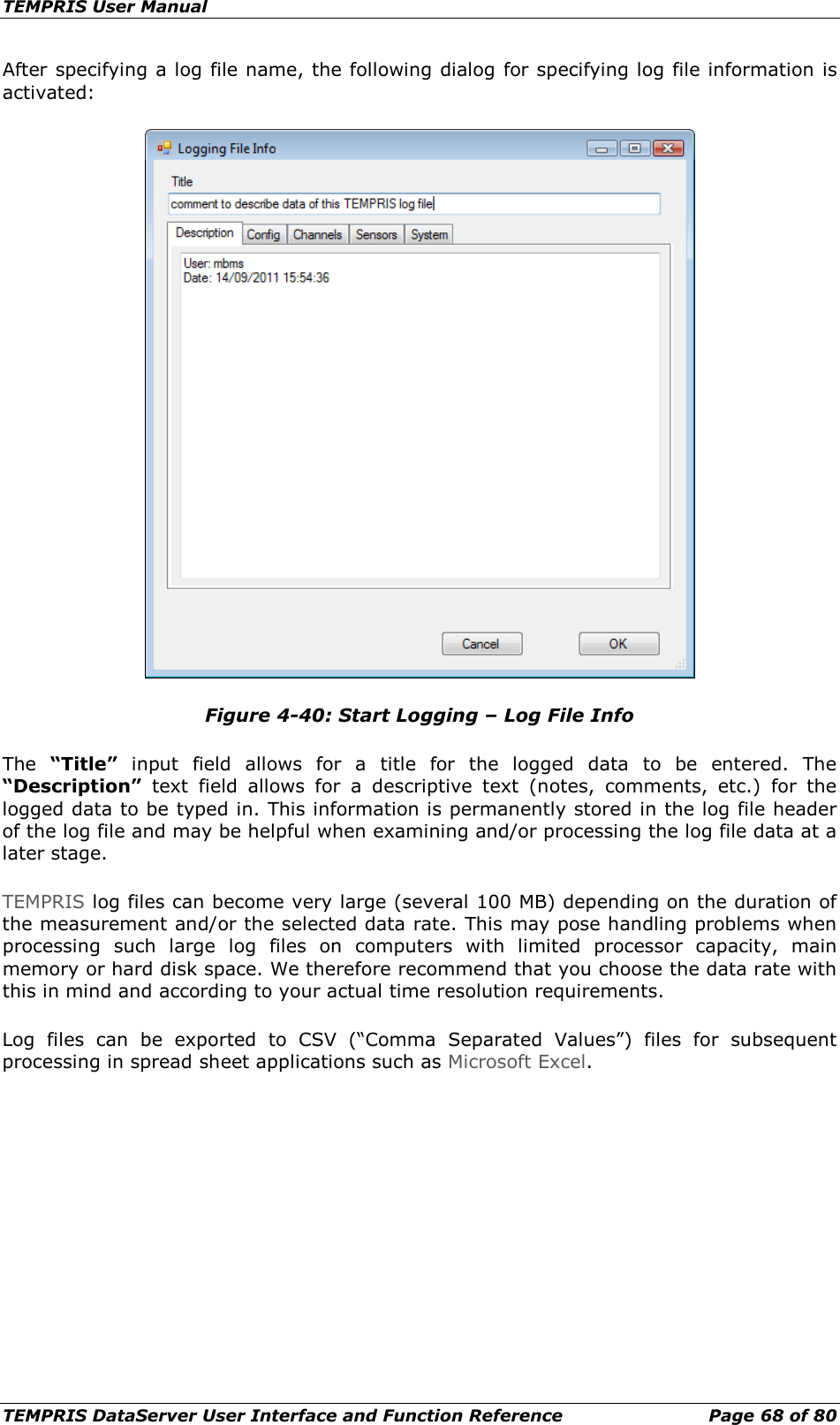
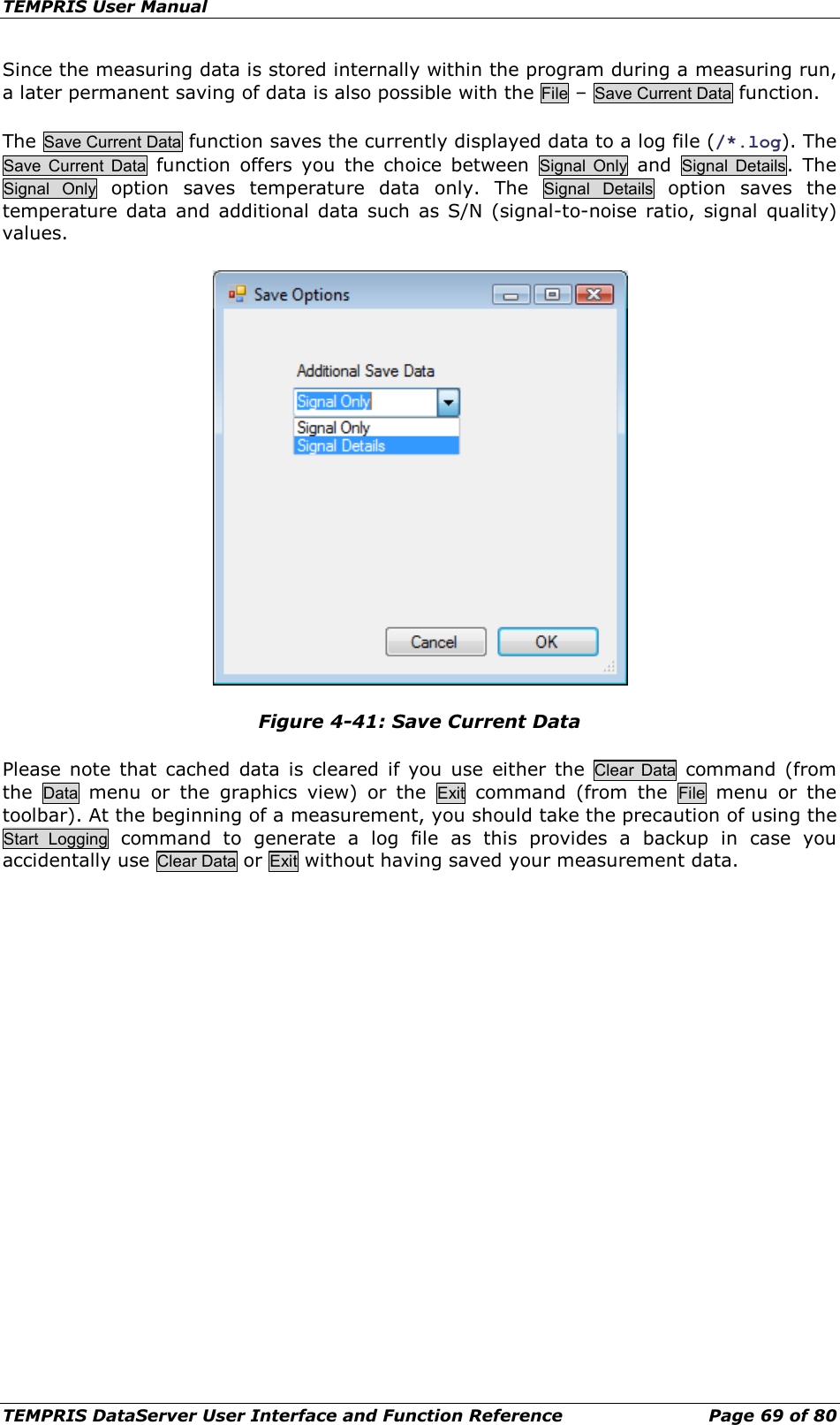
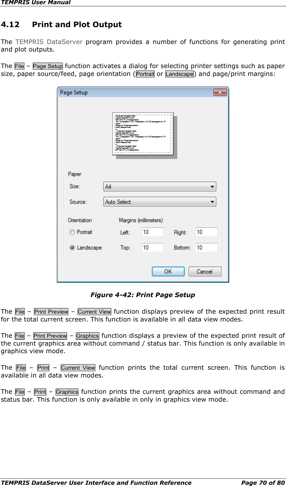
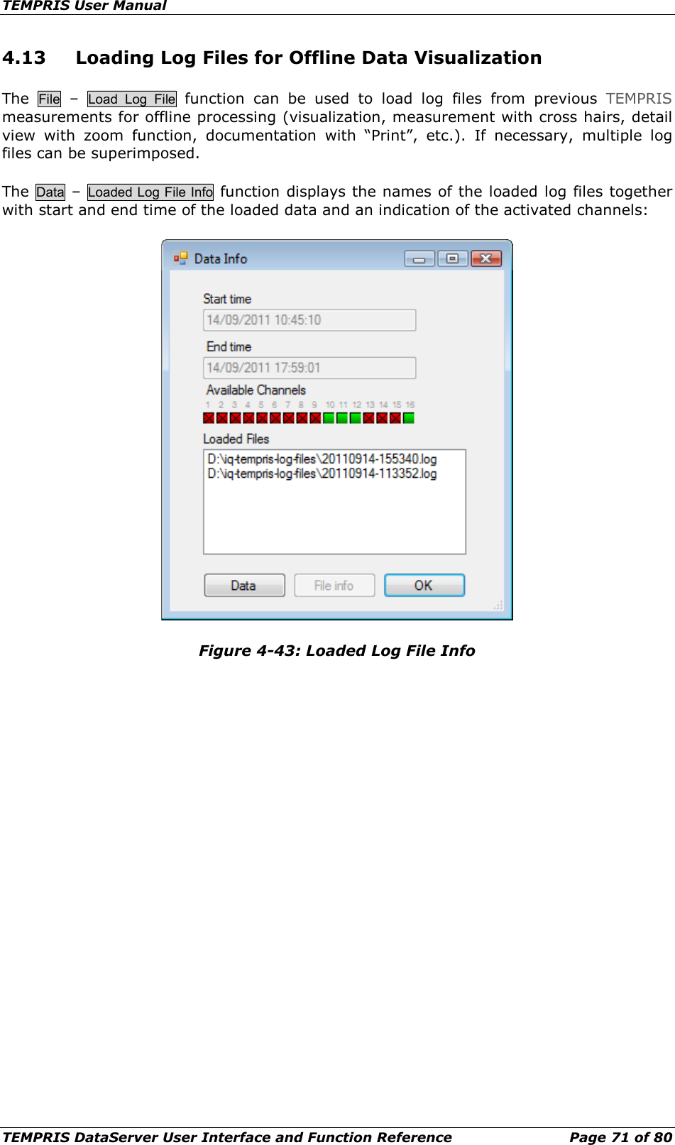
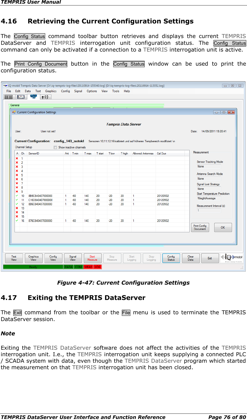
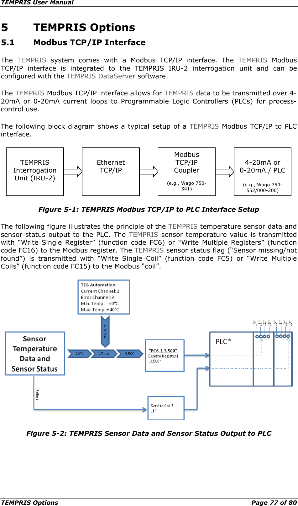
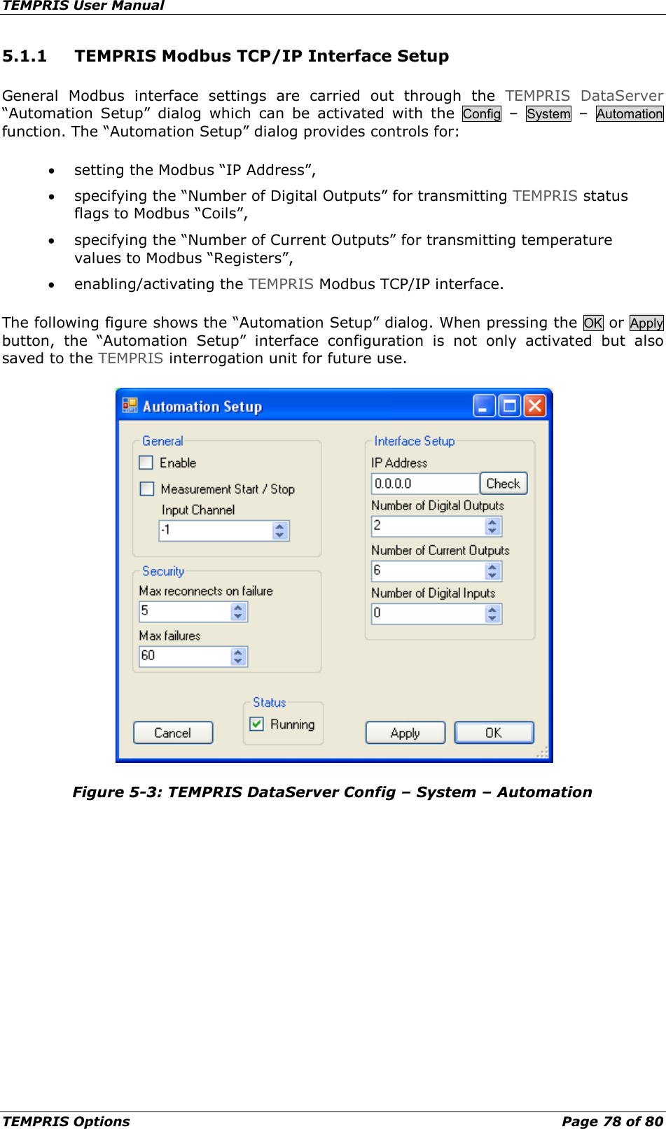
![TEMPRIS User Manual Important Information Page 10 of 80 Symbolic Conventions The following symbolic conventions are used throughout the TEMPRIS documentation: Lineprint Lineprint font represents text output generated by the system. Boldface Boldfaced words or characters in format or command descriptions represent topic definitions or syntactic terminals, i.e., commands or keywords to be inserted directly. Emphasize Emphasized text is used for optical accentuation. " " Double quotes denote names and/or path names or enclose characters and/or character sequences directly to be inserted. [ ] Square brackets enclose optional items in format or command descriptions or physical unit designators in normal text. { } Braces enclose a list of items in format or command description, from which one has to be chosen. | A vertical bar separates items in a list of choices. < > Angle brackets enclose the logical name of a key on the keyboard. In format or command descriptions, angle brackets enclose values to be supplied. > Boldfaced greater signs in line print font are used for denoting prompts on operating system level. ... Horizontal ellipsis points indicate either optional repetition of the preceding element in format or command descriptions or absence of irrelevant parts of a figure or example. : Vertical ellipsis points indicate absence of irrelevant parts of a figure, an example or a format or command description. a b ... Keyboard (input) - standard key(s) F1 F2 ... Keyboard (input) - function key(s) filename File or directory path name. keyword Topic definitions or syntactic terminals, i.e., commands or keywords to be inserted directly. message TEMPRIS DataServer / system status or error message display. Menu TEMPRIS DataServer function menu. Menu Function TEMPRIS DataServer menu function. Menu Option TEMPRIS DataServer menu option. Button TEMPRIS DataServer dialog button. The character sequences mentioned above may regain original meaning when used in programming languages, interpreter languages, specification languages, syntax description languages, etc.](https://usermanual.wiki/IQ-mobil-solutions/TIRU/User-Guide-1911364-Page-10.png)
![TEMPRIS User Manual Important Information Page 15 of 80 1.7.2 CE Compliance Declaration of Conformity with Regard to the EU Directive 1999/5/EC (R&TTE Directive) This declaration is only valid for configurations (combinations of software, firmware and hardware) supported or provided by iQ-mobil solutions GmbH for use within the EU. The use of software or firmware not supported or provided by iQ-mobil solutions GmbH may result in the equipment no longer being compliant with the regulatory requirements. Deutsch [German] Dieses Gerät entspricht den grundlegenden Anforderungen und den weiteren entsprechenden Vorgaben der Richtlinie 1999/5/EU. English This equipment is in compliance with the essential requirements and other relevant provisions of Directive 1999/5/EC. Note: The full declaration of conformity for this product is available from iQ-mobil solutions GmbH. The following standards were applied during the assessment of the product against the requirements of the Directive 1999/5/EC: • Radio: ETSI EN 300 328, EN 62311, 1999/519/EC • EMC: EN 61000-6-2, EN 61000-6-4, EN 301 489-1, EN 301 489-17 • Safety: EN 60950-1 The CE mark and class-2 identifier are affixed to the product and its packaging. This product conforms to the following European directives: -1999/5/EC National Restrictions This product is for indoor use only. Note: The regulatory limits for maximum output power are specified in EIRP. The EIRP level of a device can be calculated by adding the gain of the antenna used (specified in dBi) to the output power available at the connector (specified in dBm). Antennas Use only the antenna(s) supplied with the product.](https://usermanual.wiki/IQ-mobil-solutions/TIRU/User-Guide-1911364-Page-15.png)

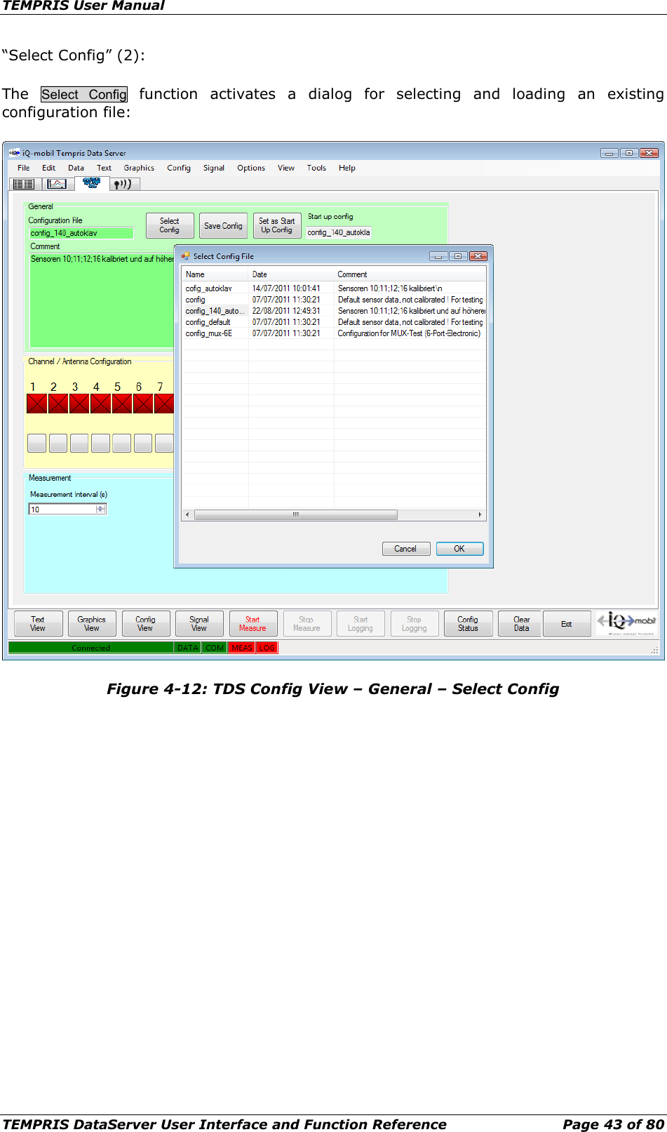
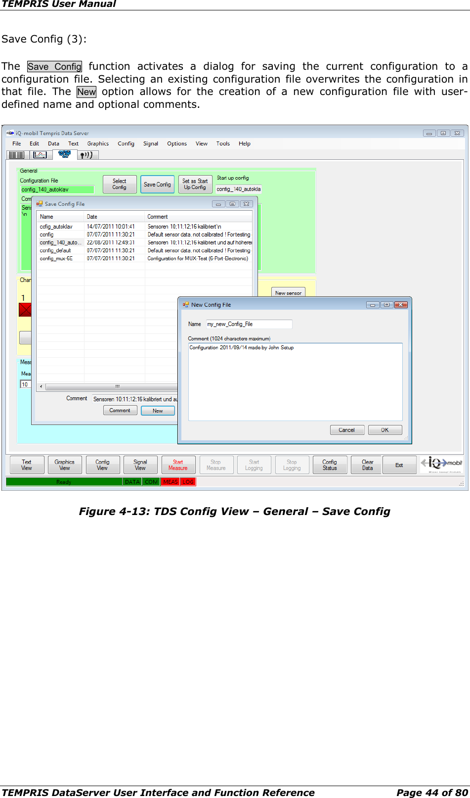
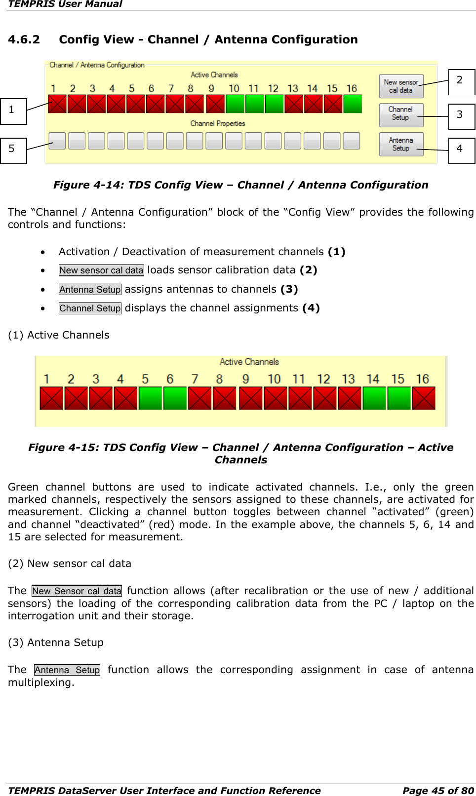
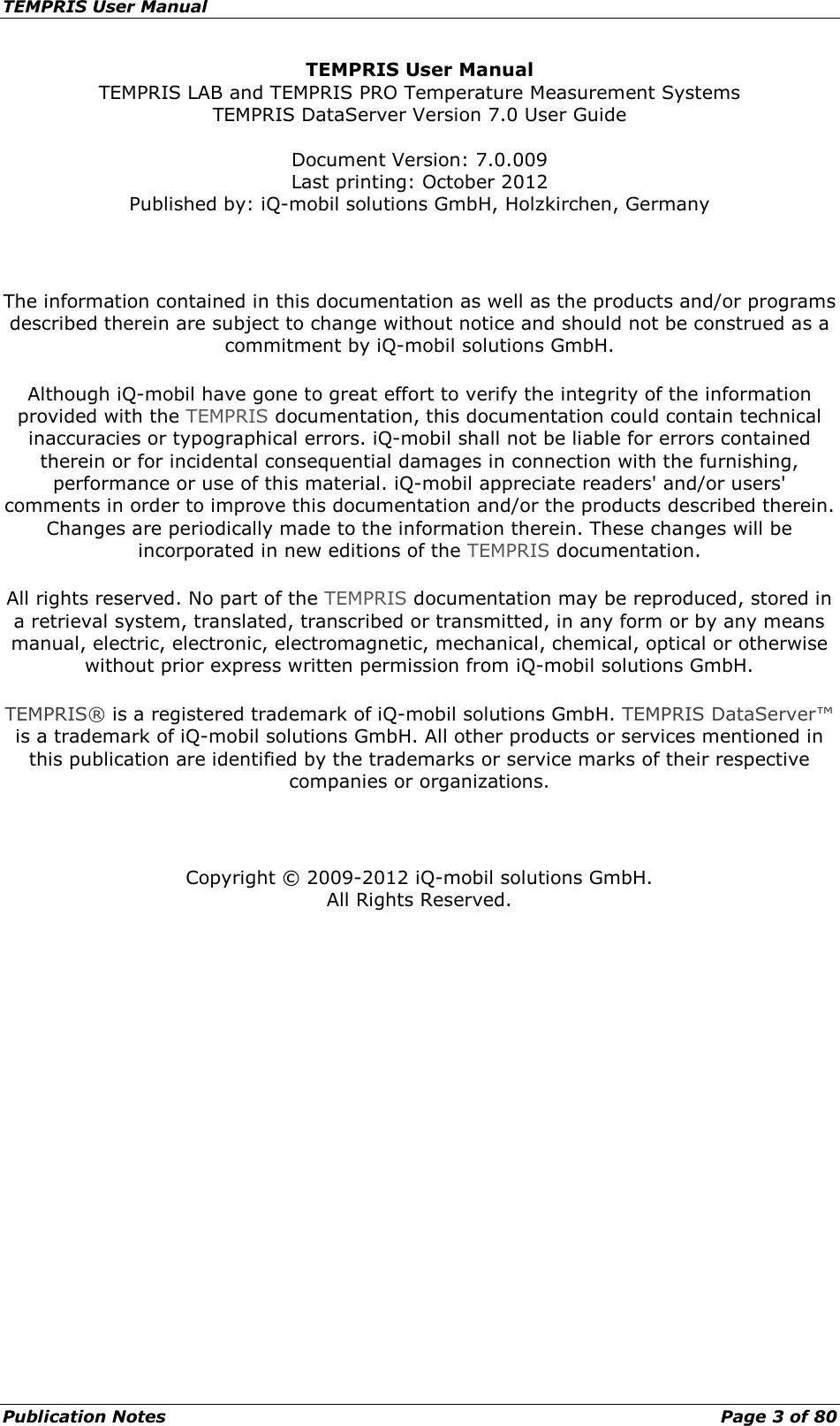
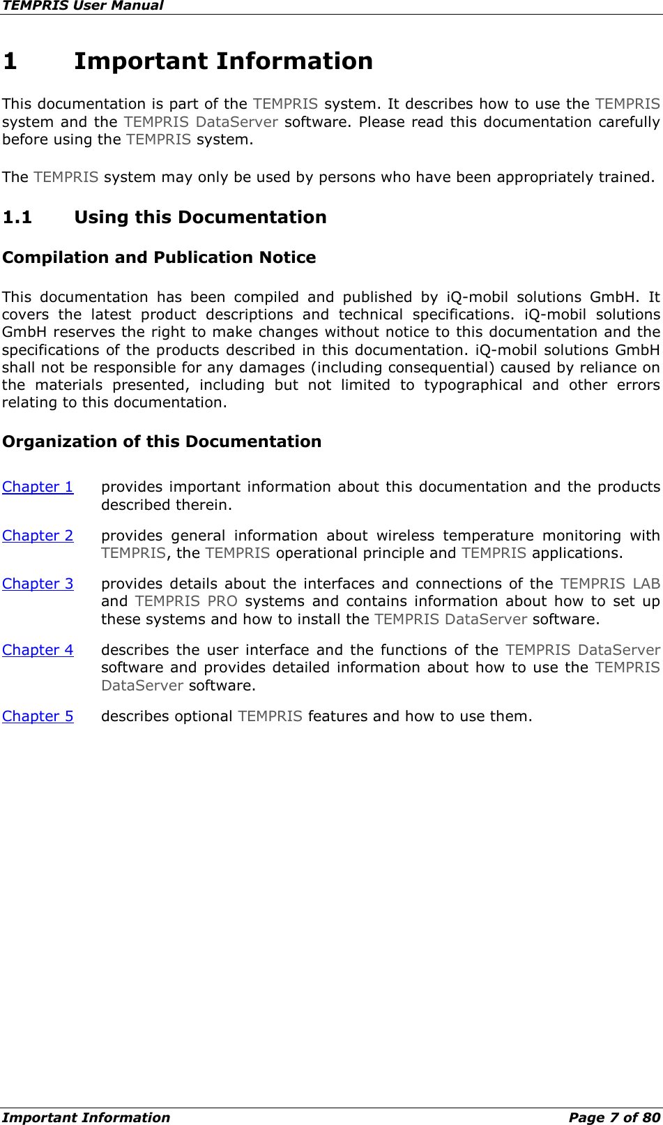
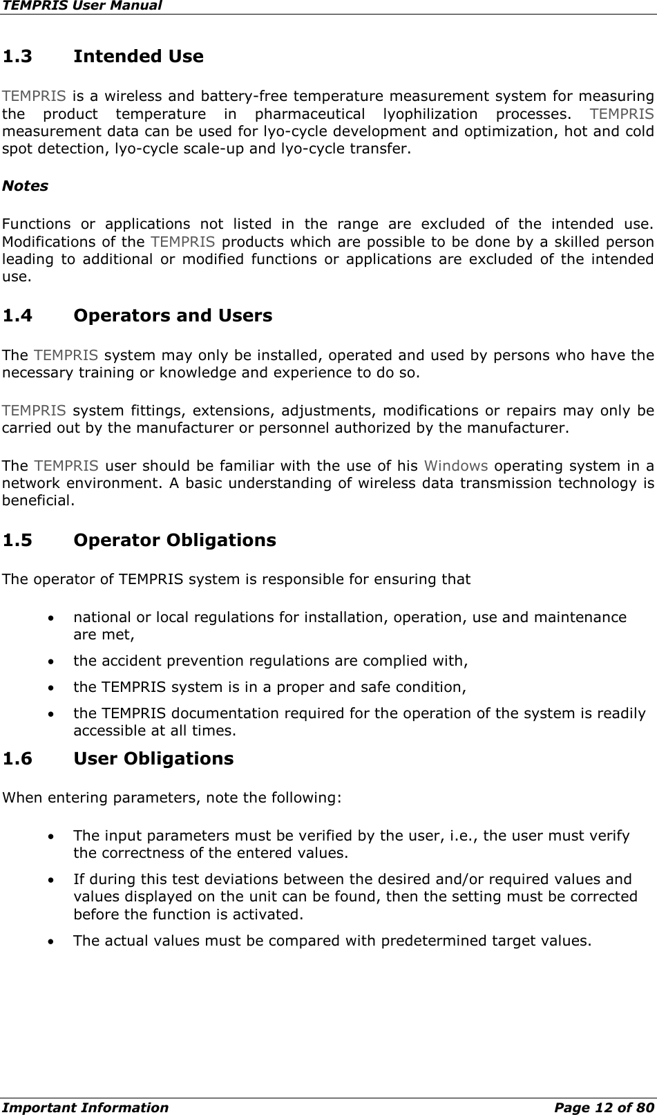
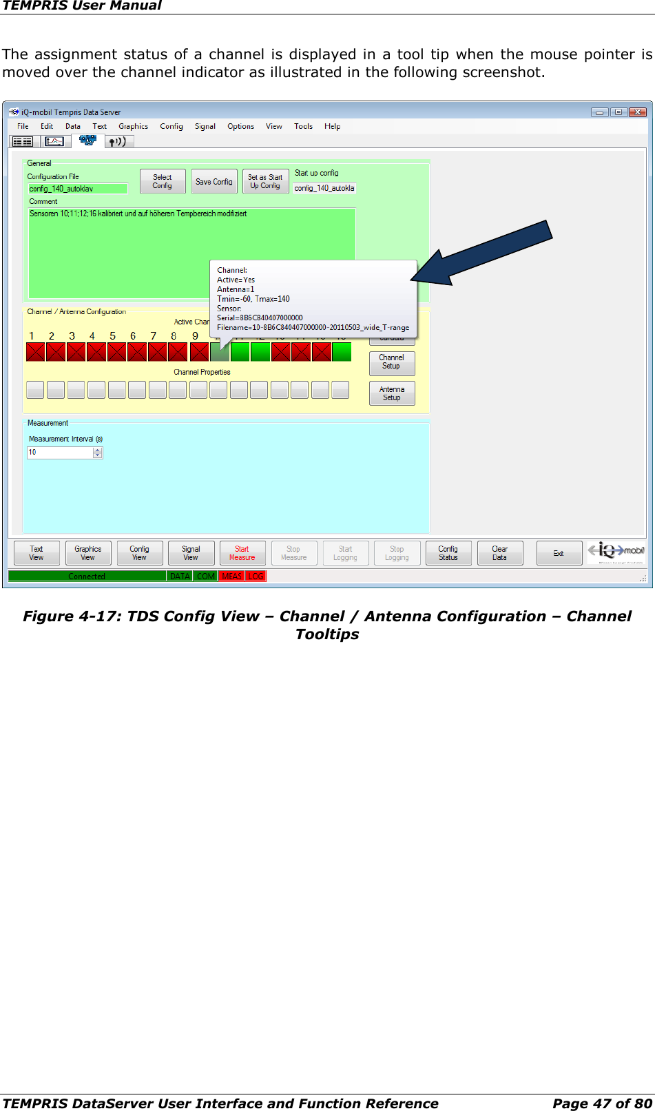
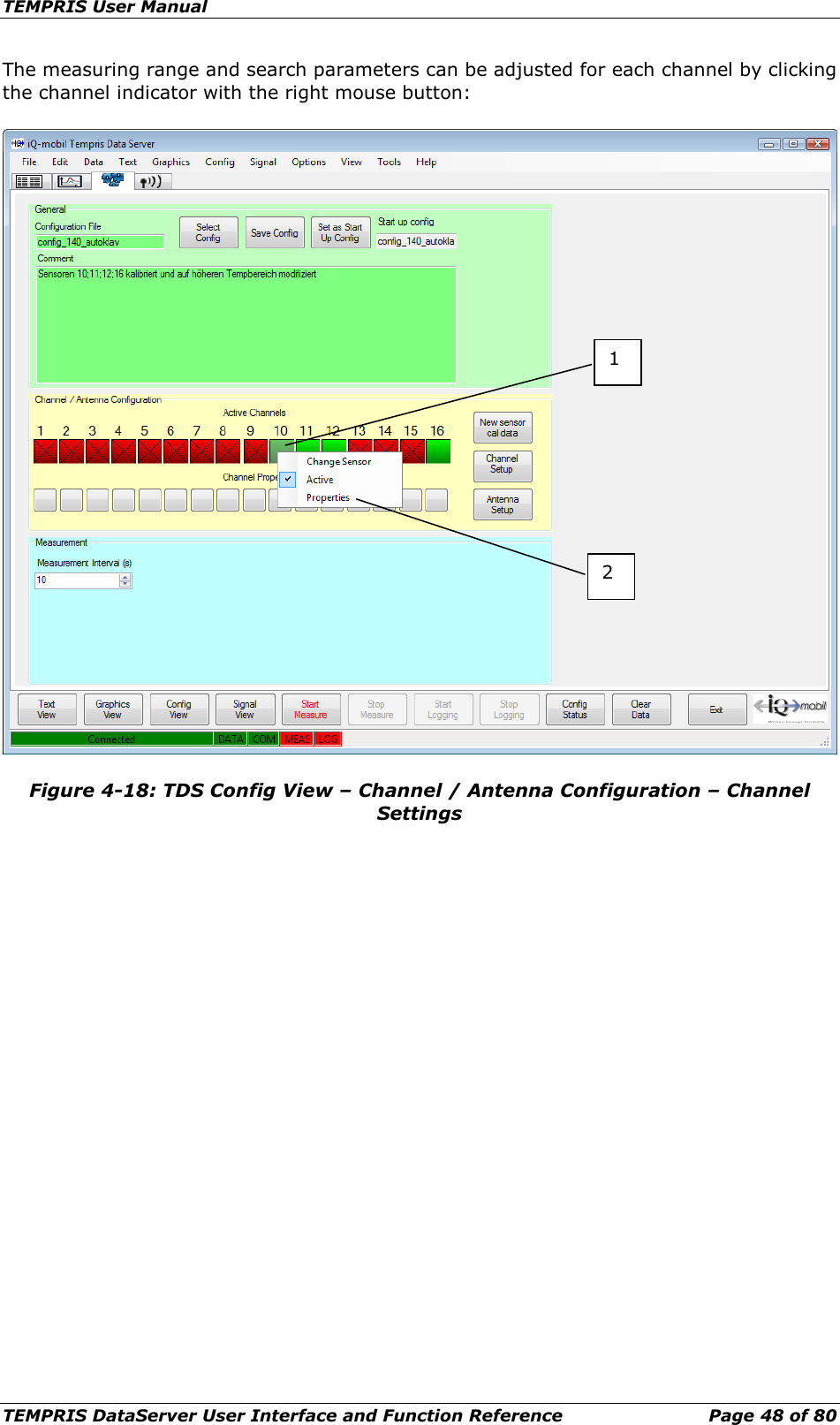
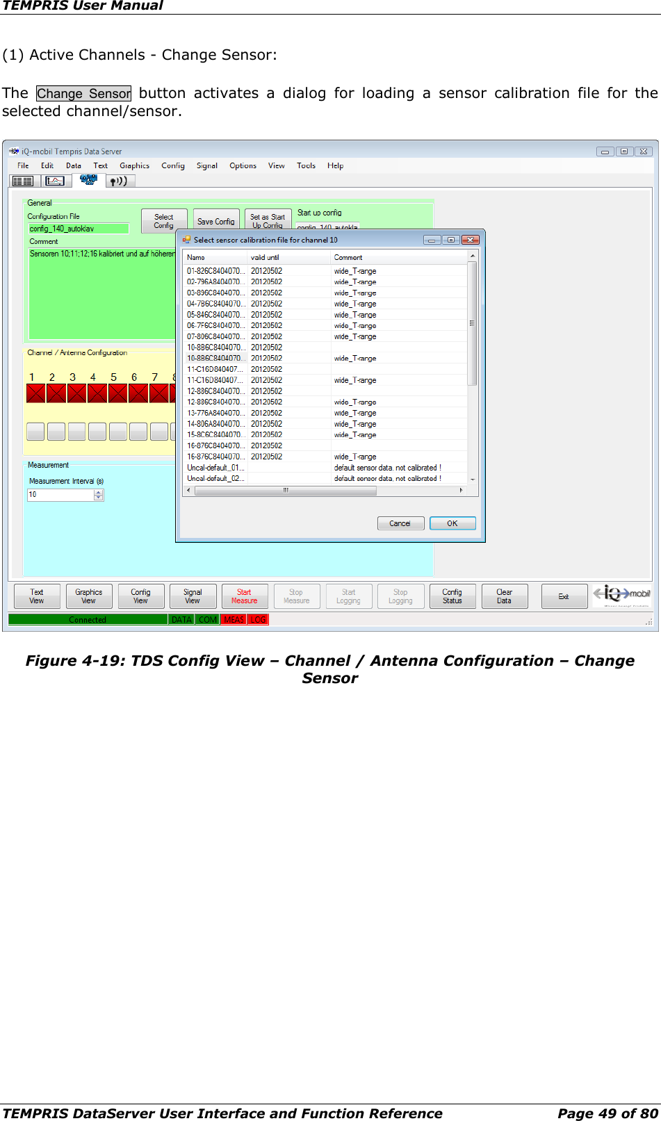
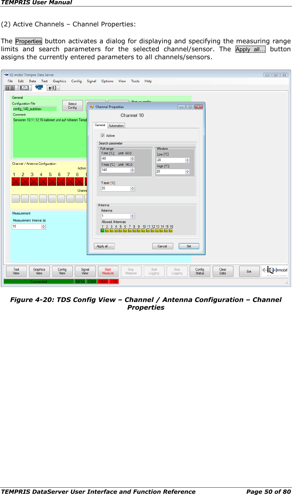
![TEMPRIS User Manual TEMPRIS DataServer User Interface and Function Reference Page 46 of 80 (4) Channel Setup The Channel Setup function allows querying the current activation status of individual channels (sensors) and corresponding measuring ranges. The following screenshot shows a channel setup query with channels 5, 6, 14 and 15 activated. Figure 4-16: TDS Config View – Channel / Antenna Configuration – Channel Setup The TEMPRIS data collection process supports different search strategies for finding the sensors in the antenna field of the TEMPRIS interrogation unit. The TEMPRIS sensor search procedure is similar to an automated channel scan on a car radio tuner. In order to search as efficiently as possible, a search area has to be selected (similar to the FM, VHF, etc. band selection on the car radio tuner). The TEMPRIS search area is defined through the following temperature parameters: • Tmin Temperature measuring range lower limit [°C] • Tmax Temperature measuring range upper limit [°C] • Tstart Temperature search start value [°C] • Tlow Temperature search range lower limit [°C] • Thigh Temperature search range upper limit [°C]](https://usermanual.wiki/IQ-mobil-solutions/TIRU/User-Guide-1911364-Page-46.png)
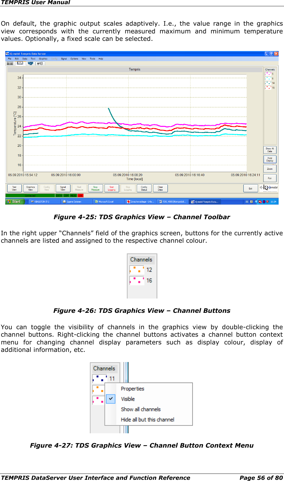
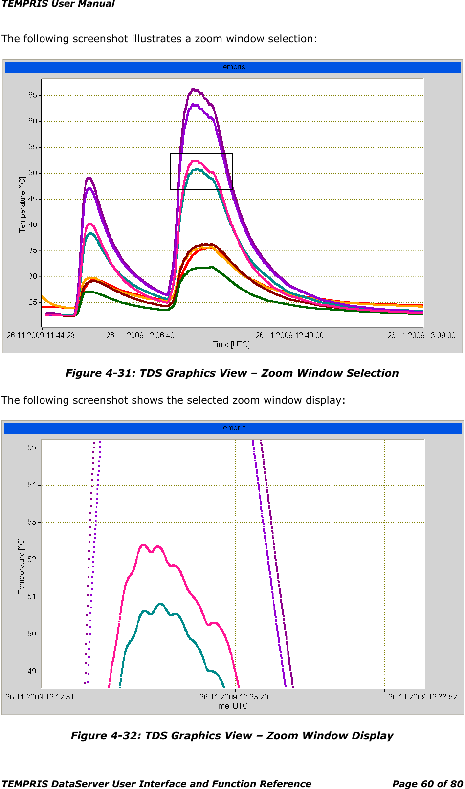
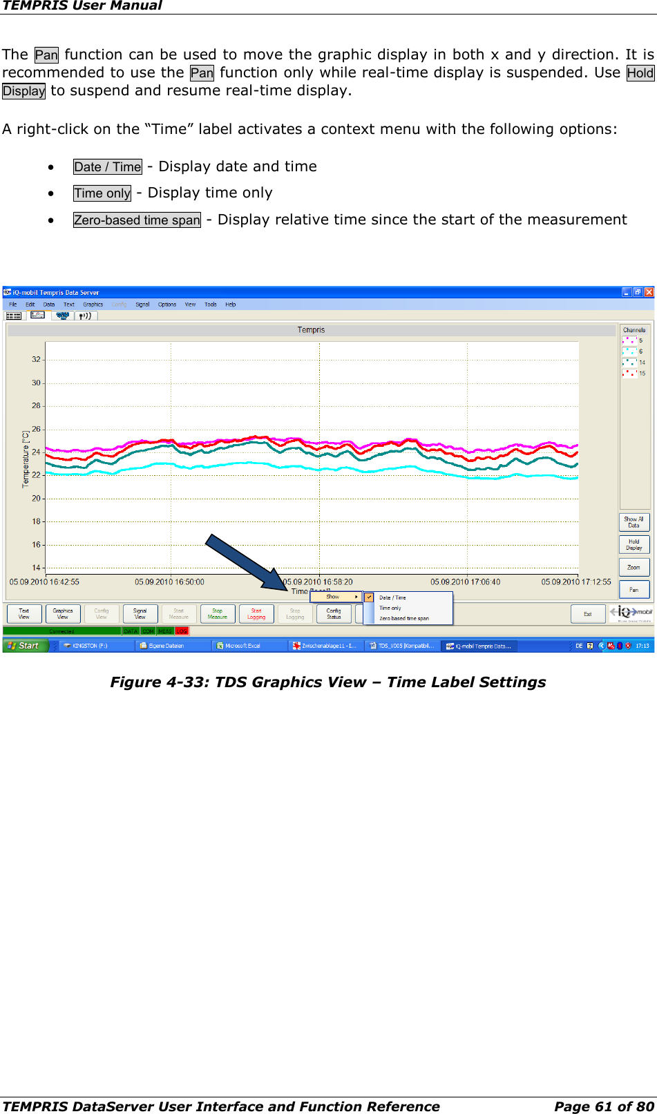
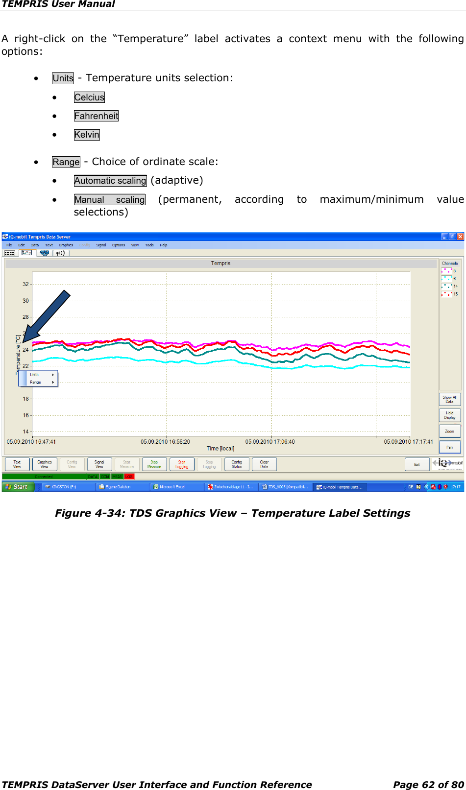
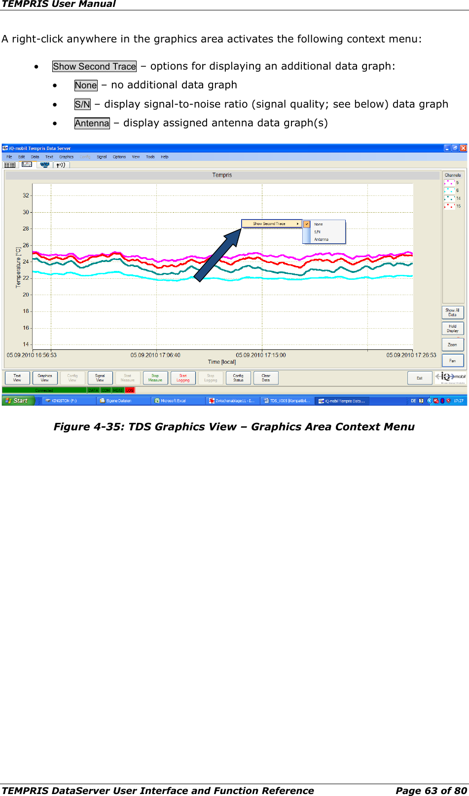
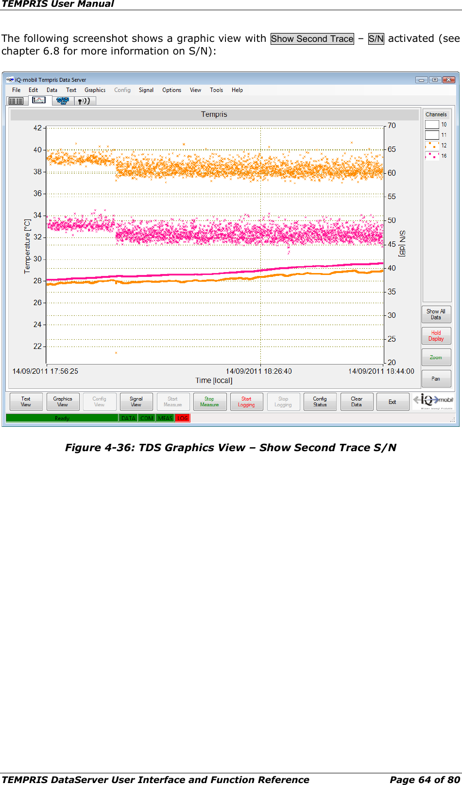
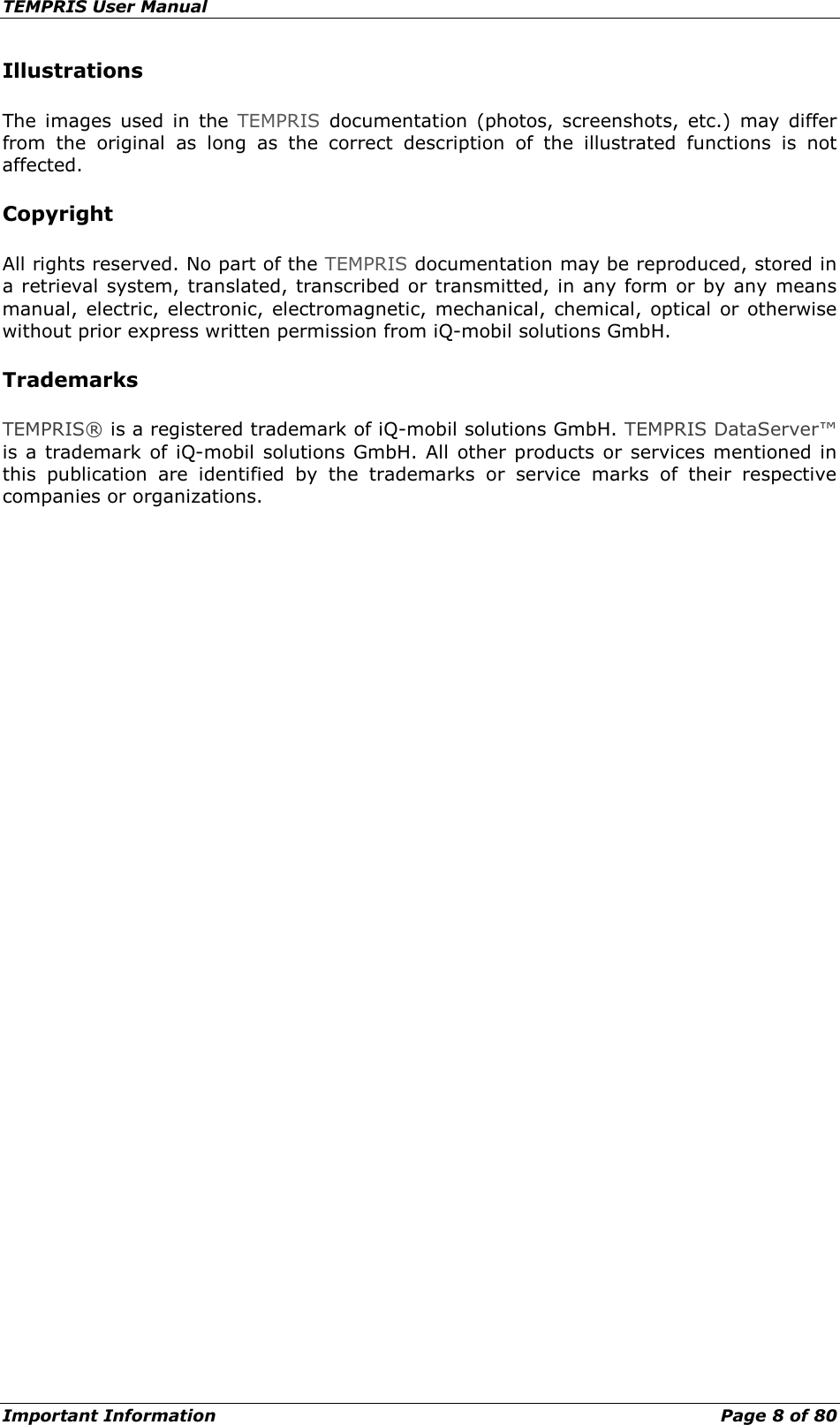
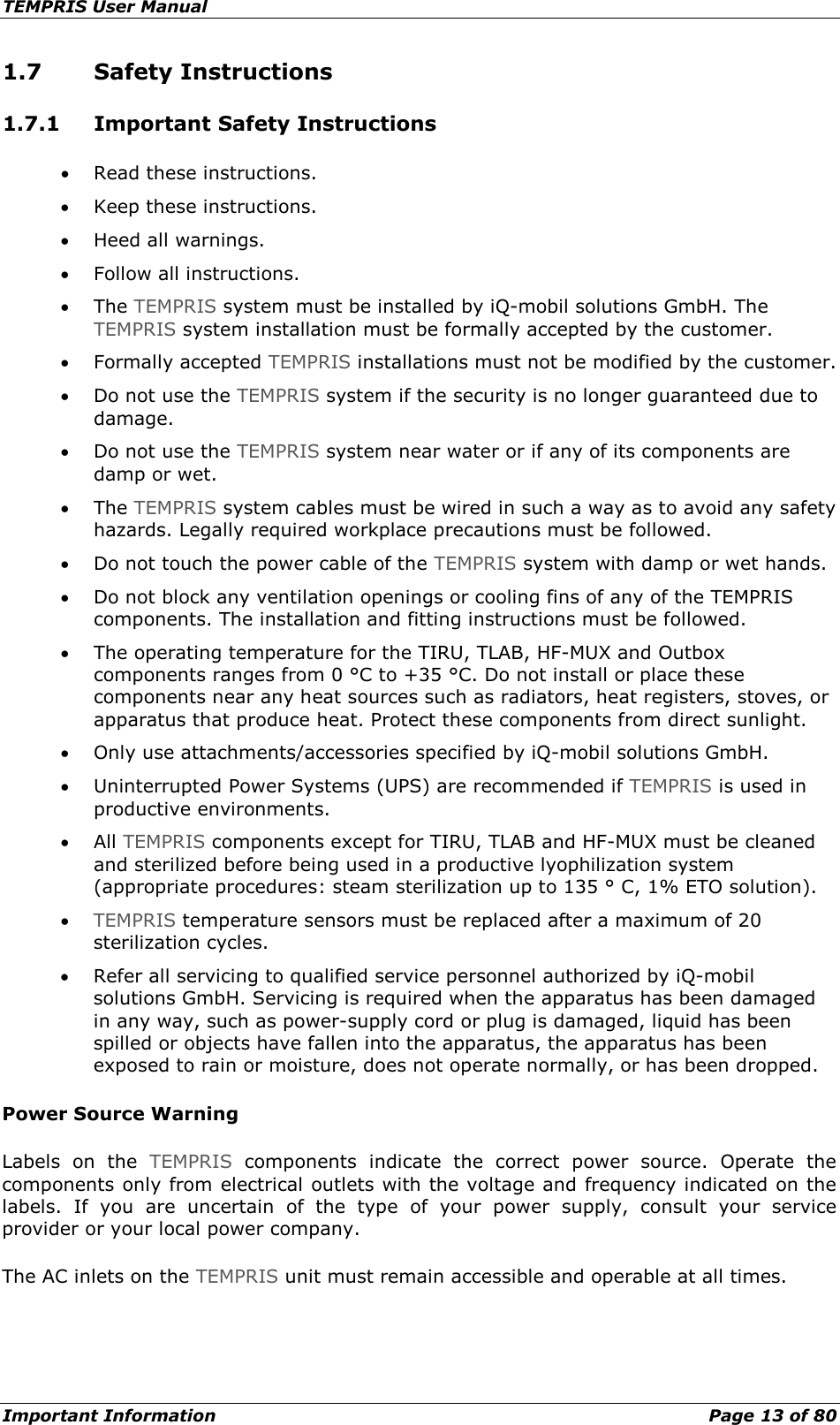
![TEMPRIS User Manual TEMPRIS DataServer User Interface and Function Reference Page 55 of 80 4.8 Graphics View The „Graphics View“ displays a plot data view of the monitored data. The graphics view can be activated through the Graphics View function from the View menu or by clicking the corresponding function index tab. Figure 4-24: TDS Graphics View The ordinate (y-axis) of the graph represents the temperature in the chosen temperature unit (Celsius, Fahrenheit, Kelvin). The abscissa (x-axis) represents the time in UTC (Coordinated Universal Time; “Time [UTC]”) or local time (“Time [local]”) as selected through Options – Show Local Time.](https://usermanual.wiki/IQ-mobil-solutions/TIRU/User-Guide-1911364-Page-55.png)