Image Sensing Systems RTMS-K4S RTMS K4 User Manual
Image Sensing Systems, Inc. RTMS K4
UserManual.wiki
>
Image Sensing Systems
>
RTMS K4S User Manual
User Manual
Navigation menu
Upload a User Manual
Namespaces
Wiki Guide
HTML
PDF
Info
Views
User Manual
Discussion / Help
Navigation
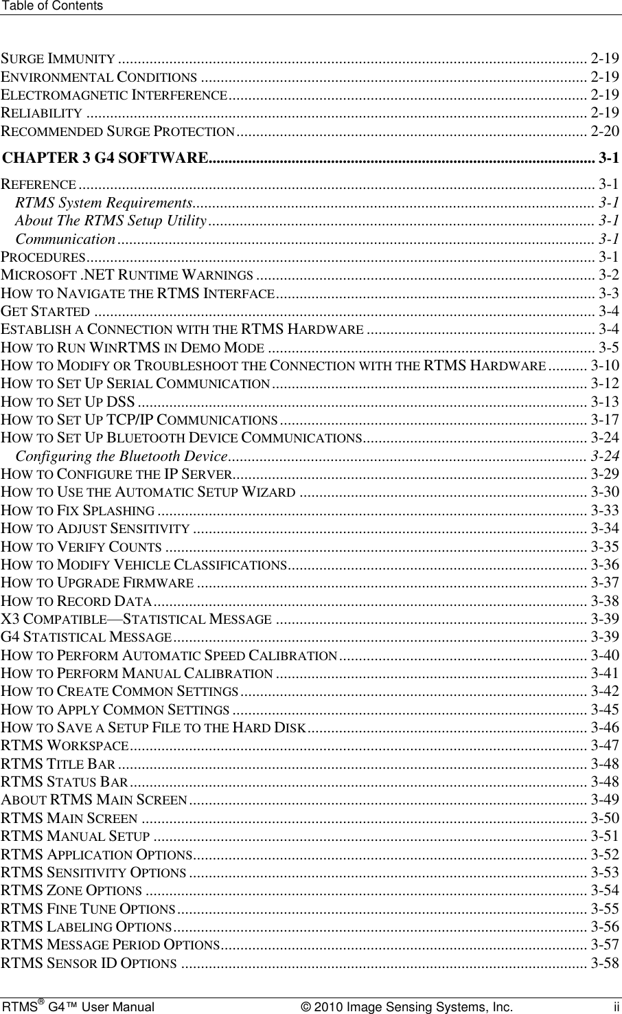
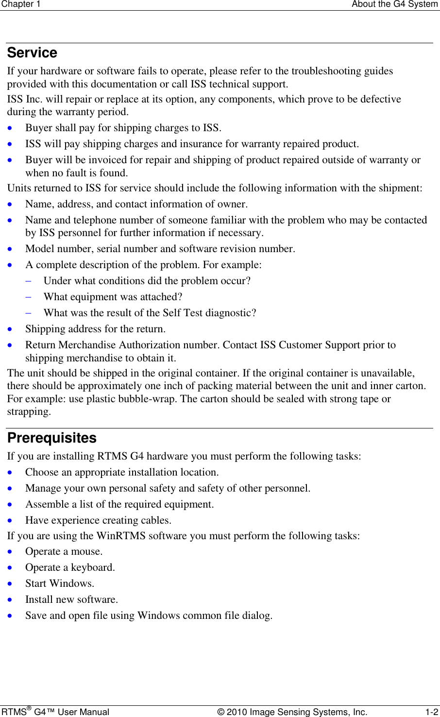
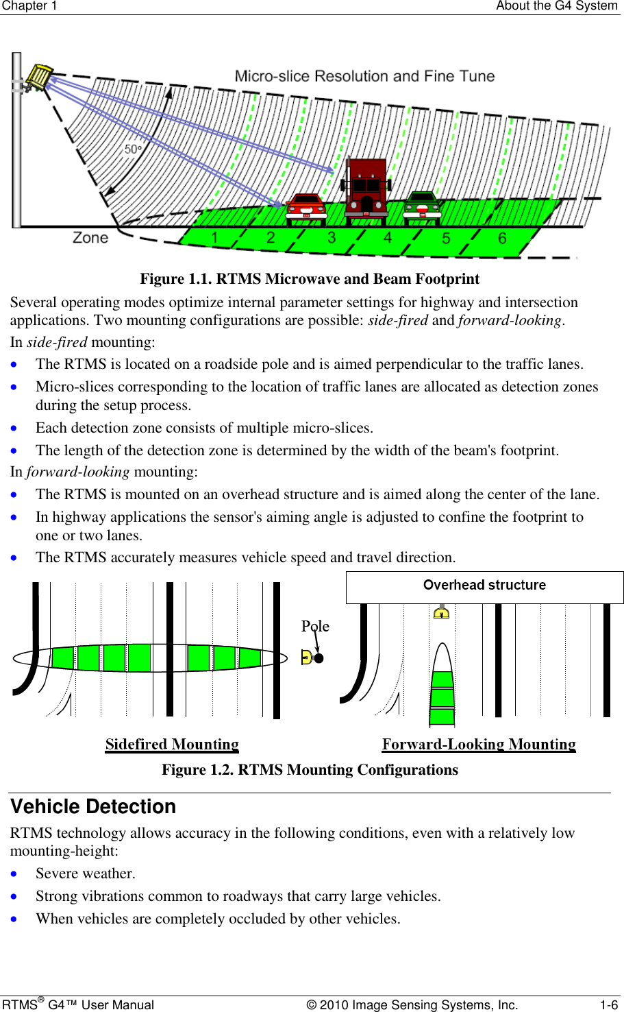
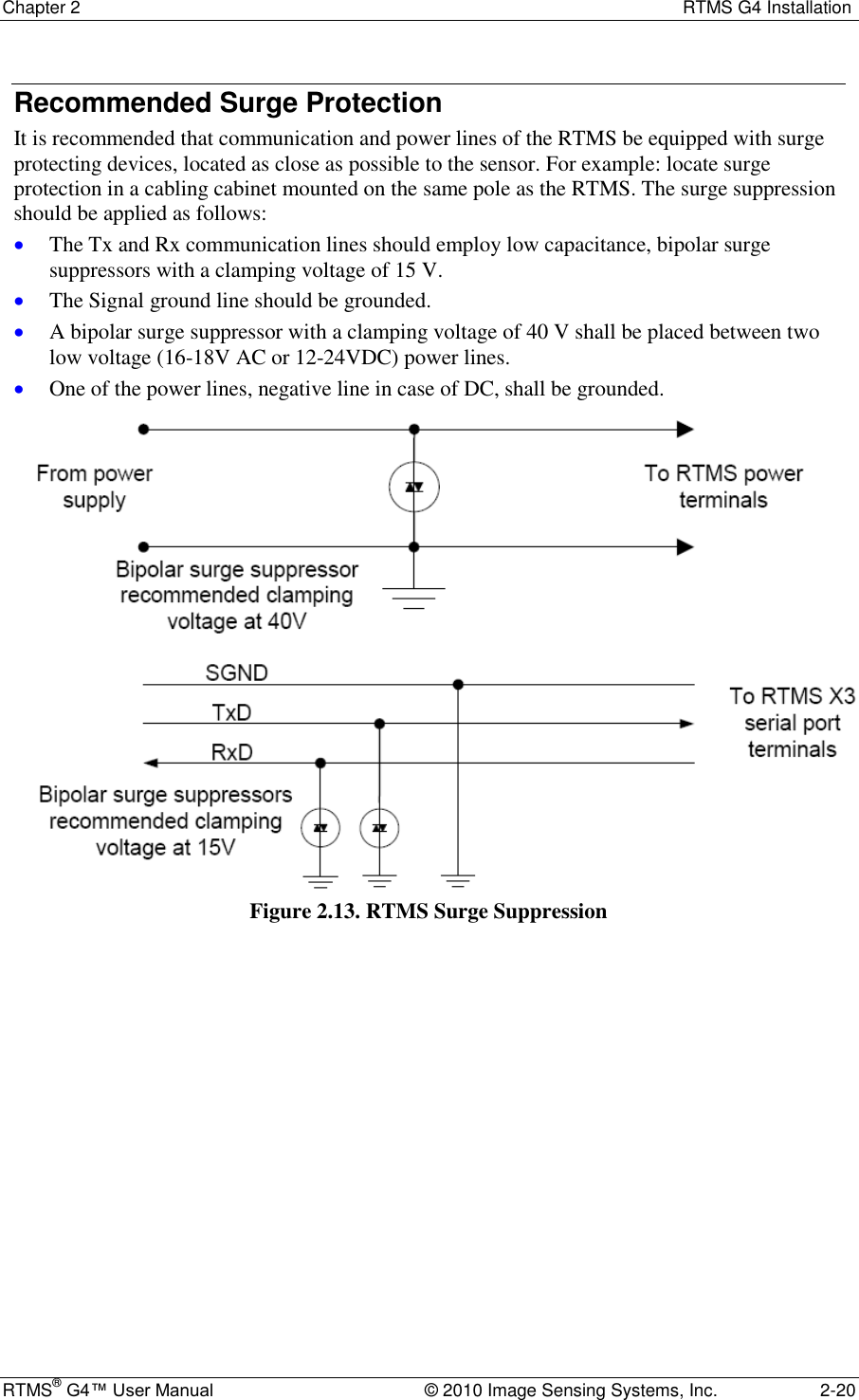
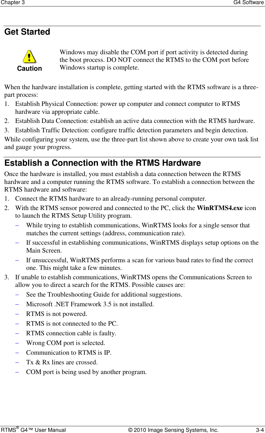
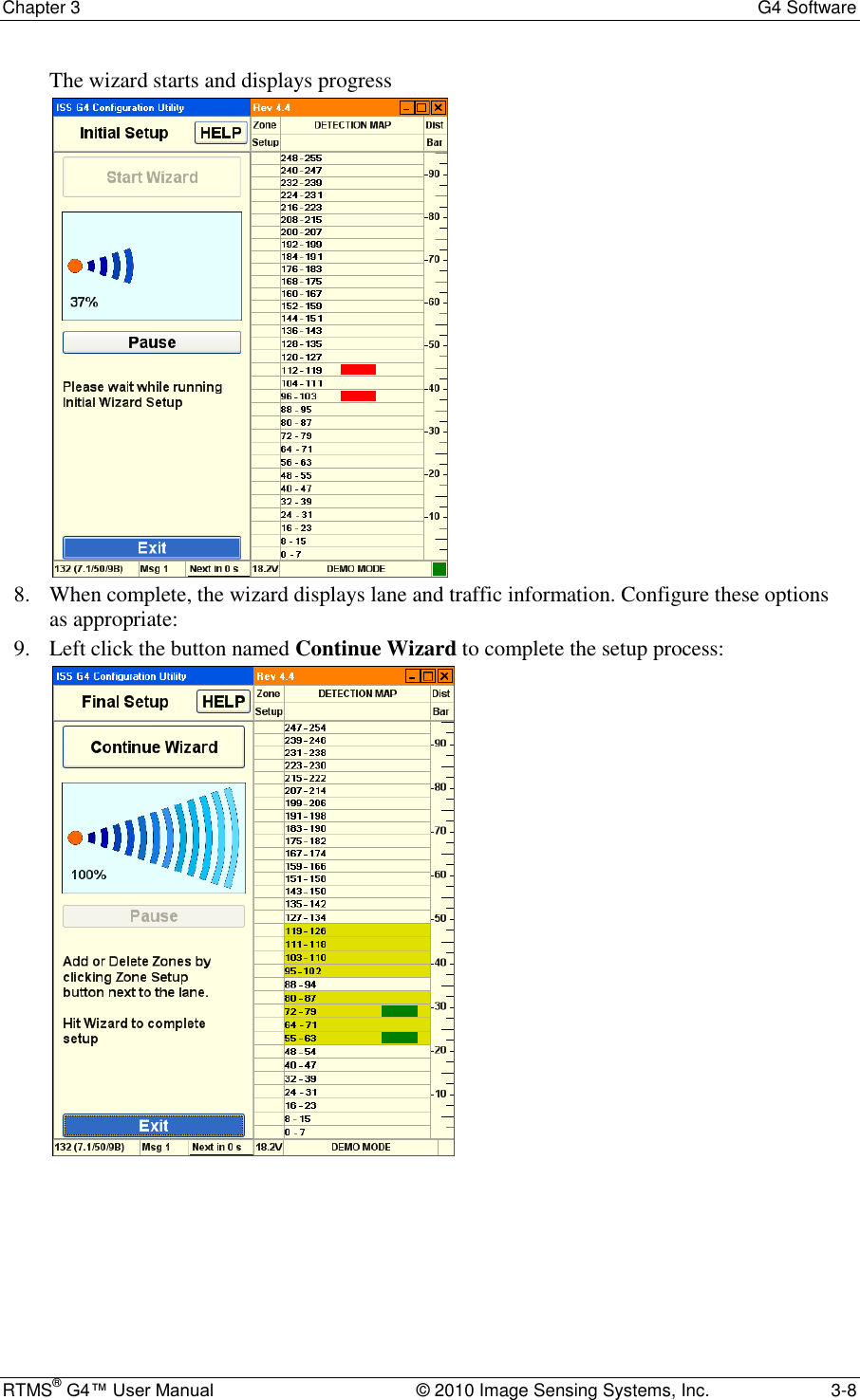
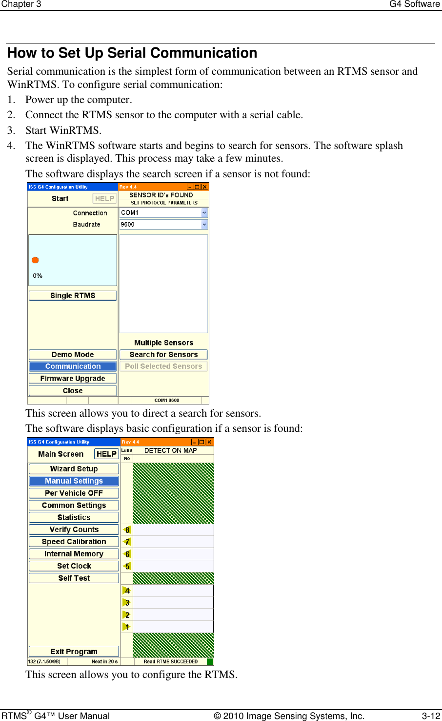
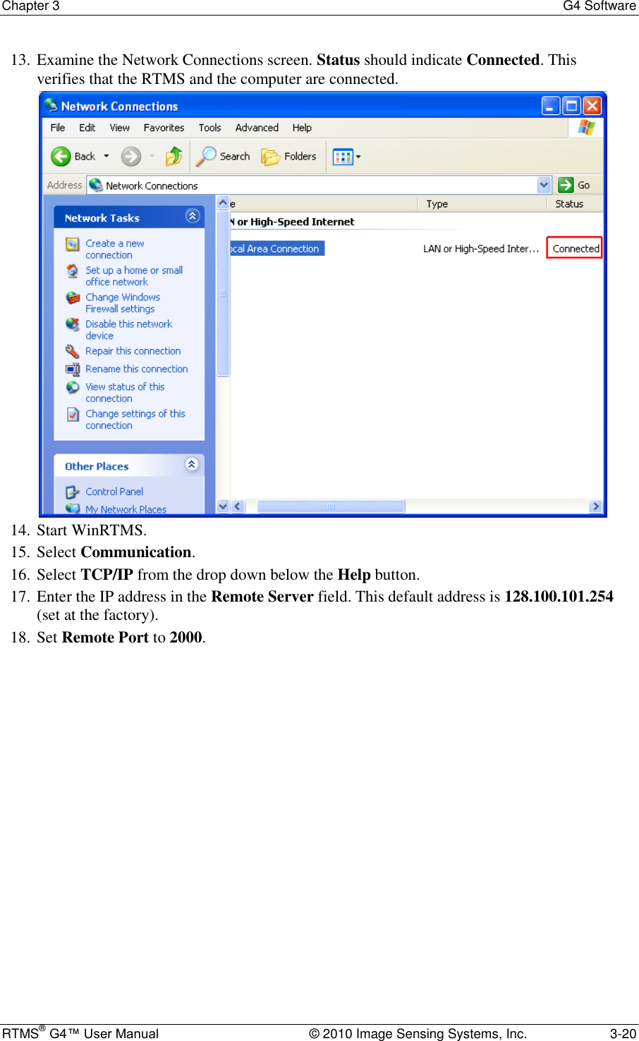
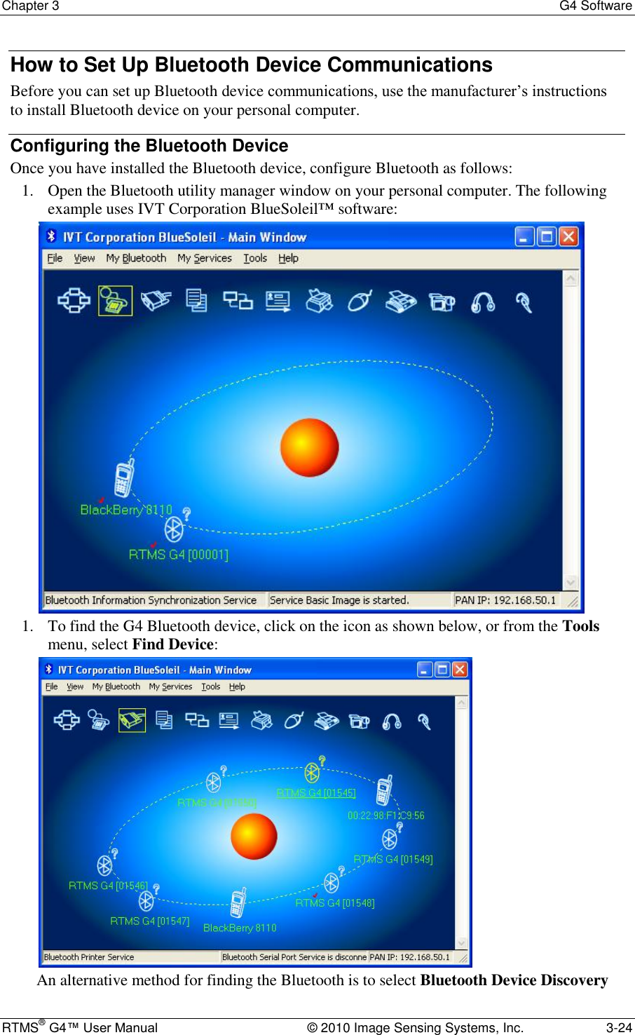
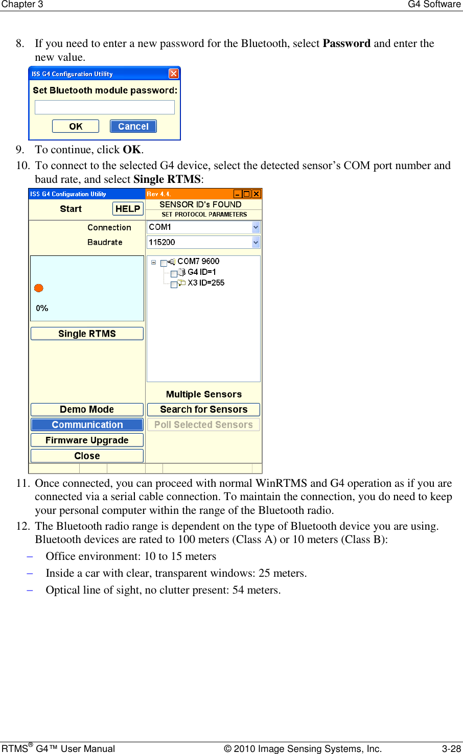
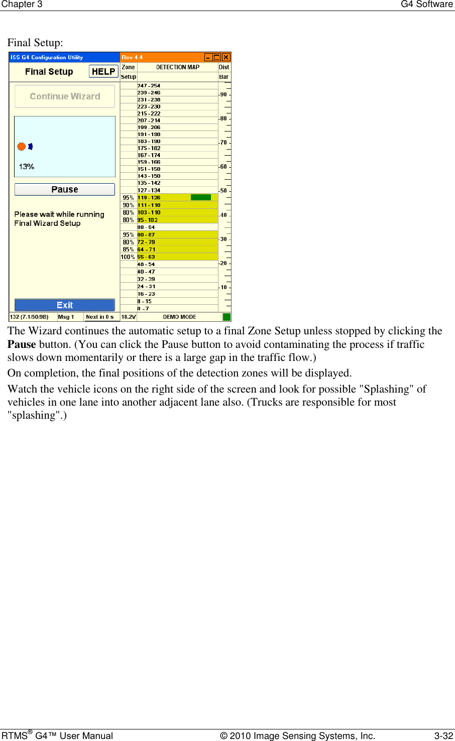
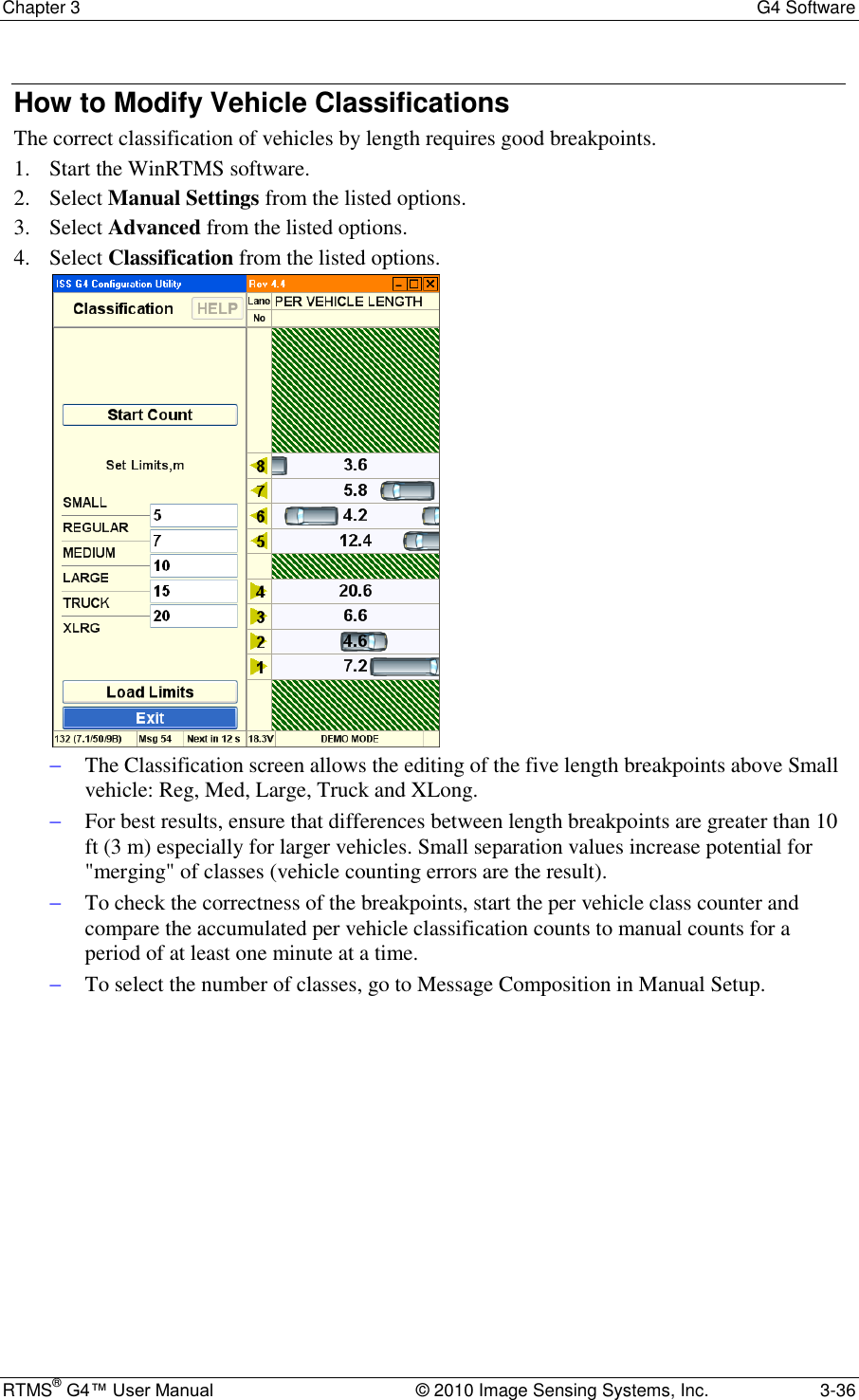
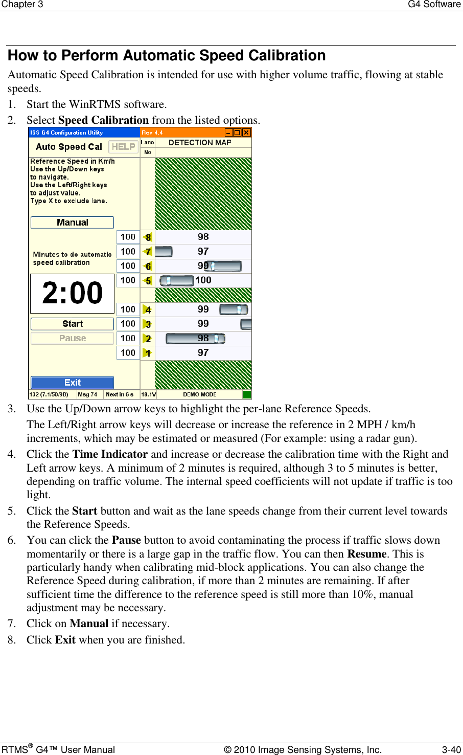
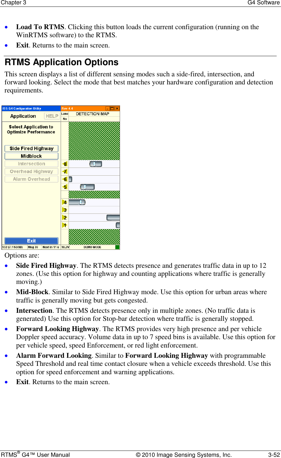
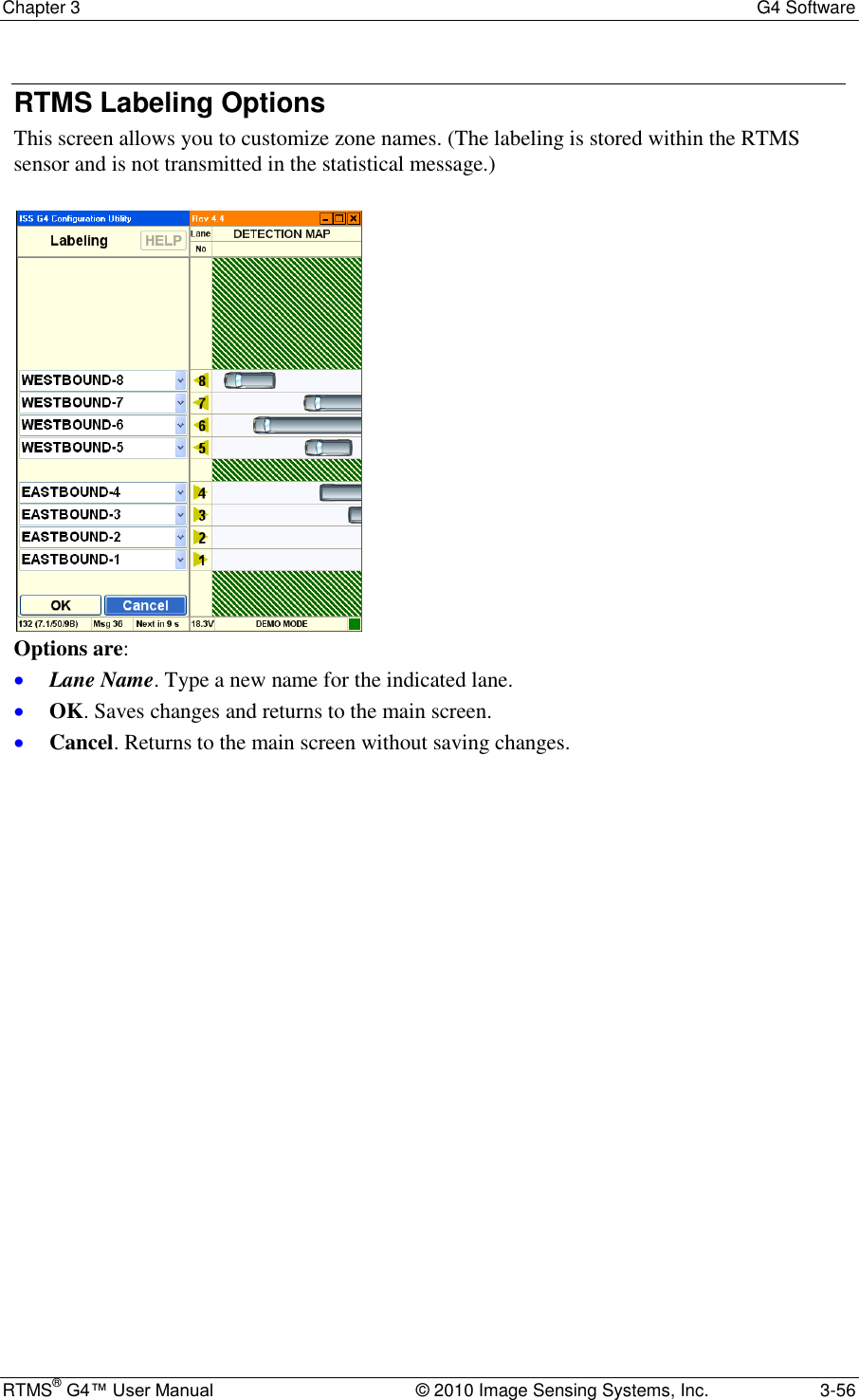
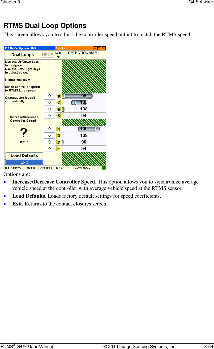
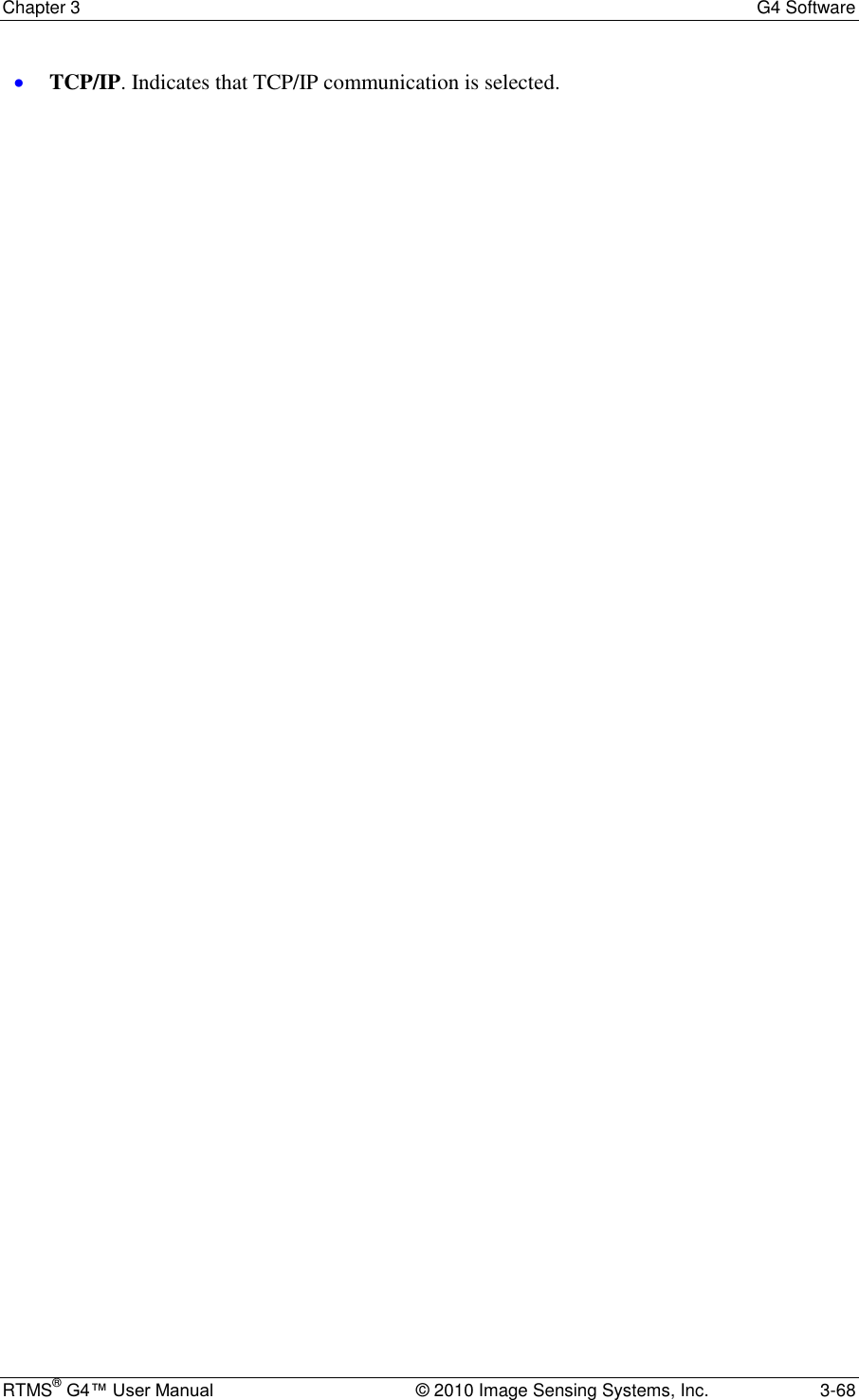
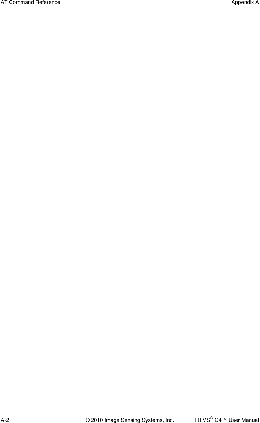
![RTMS® G4™ User Manual © 2010 Image Sensing Systems, Inc. 2-1 Chapter 2 RTMS G4 Installation Side-Fired Mounting and Aiming The distance between the close edge of the first lane of traffic to be monitored and the front of the structure on which the RTMS is mounted is referred to as set-back. Set-back is a limiting installation parameter of the RTMS. More lanes can be covered with a larger set-back. Use the diagrams in Figures 2.1, 2.2, and 2.3 to determine the setback required to monitor a given number of lanes. The correct installation height can be determined once the set-back is set. Height is measured relative to the road surface of the detection area. Do not measure height from the bottom of the mounting pole. Example: For 3 lanes the minimum set-back is 5 feet [1.5 m]. Note It is almost always better to be 20 feet [6 m] further back from the minimum than 2 inches [5 cm] closer than the minimum. If real estate is available, move the RTMS further back. The mounting height is based on the setback. Using the correct height value allows the RTMS to be aimed so that it receives maximum return signal while covering all required lanes. Mounting the RTMS at an incorrect height will reduce accuracy. Median strips are equivalent to lanes and must be included in total lane count. For example: an eight lane road with a two lane-wide median strip has 10 equivalent lanes. Figure 2.1. RTMS Aiming](https://usermanual.wiki/Image-Sensing-Systems/RTMS-K4S/User-Guide-1591677-Page-13.png)
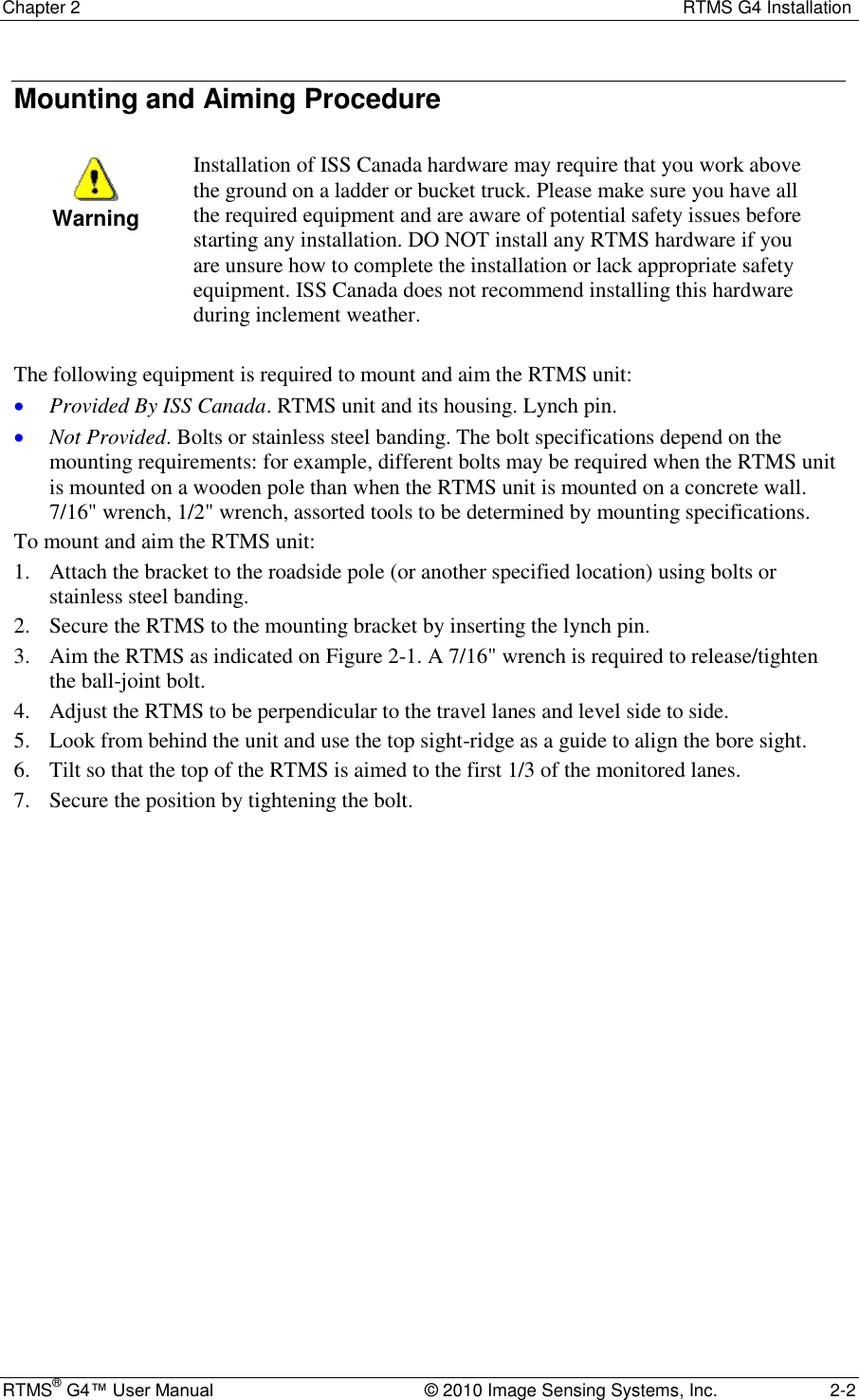
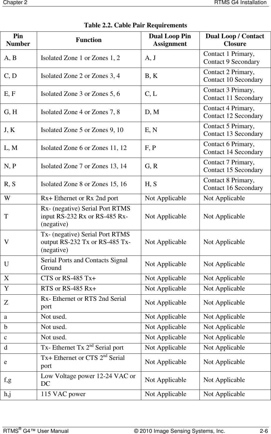
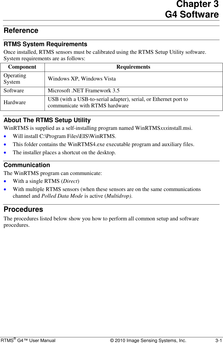
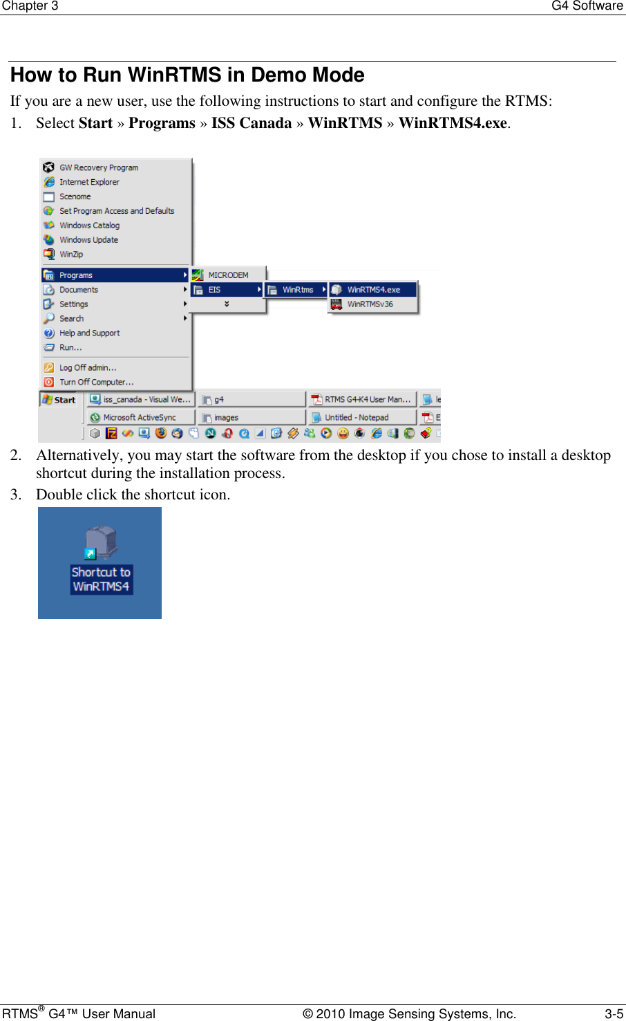
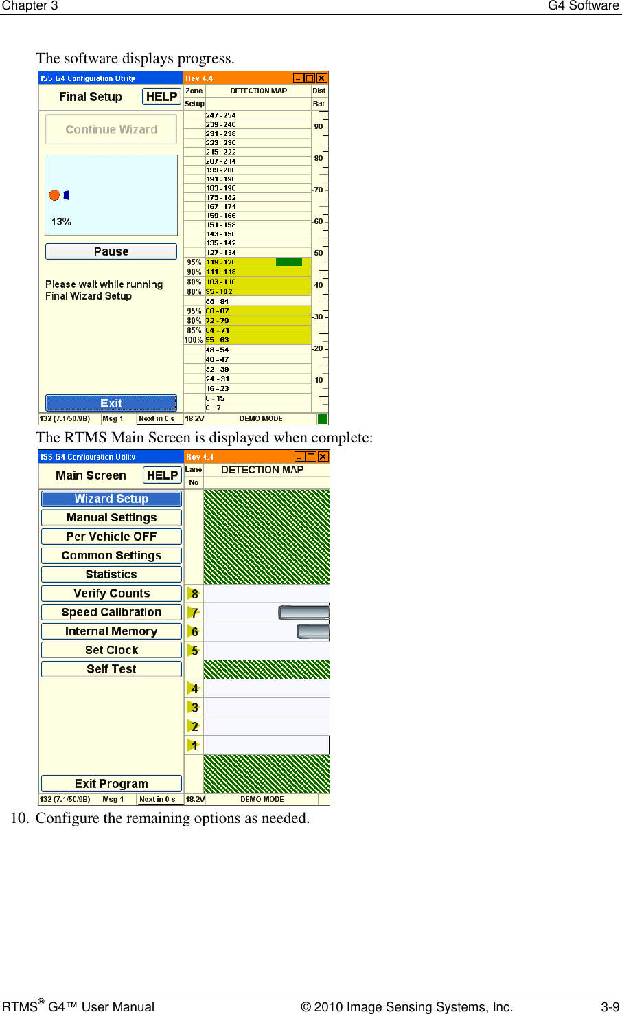
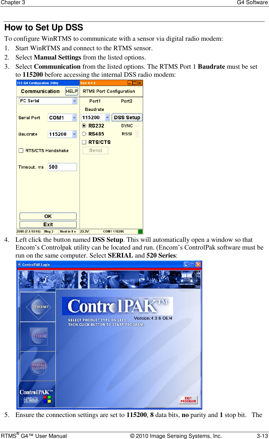
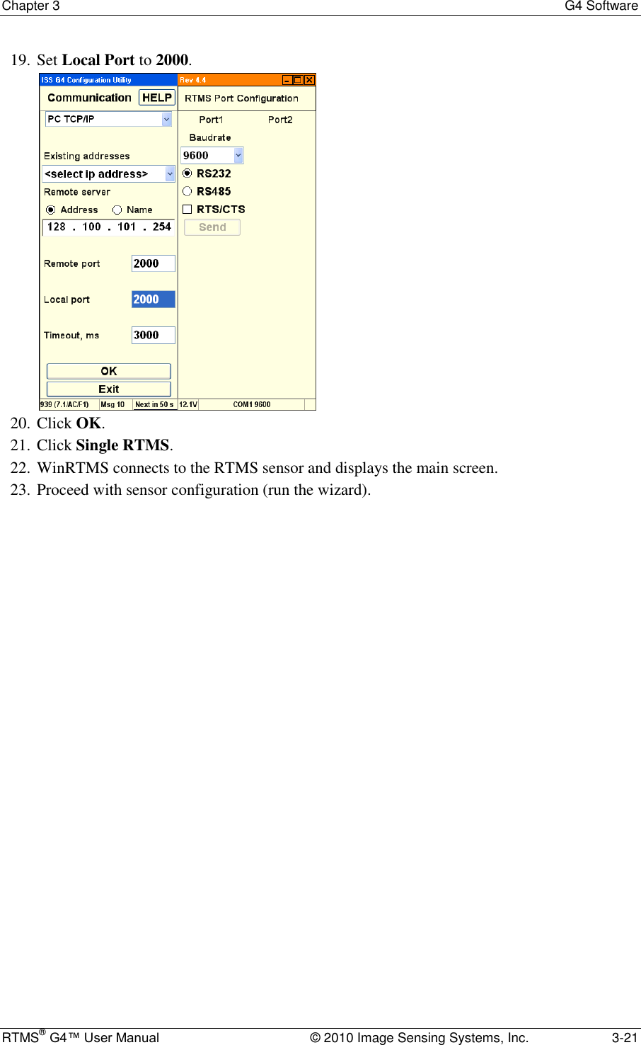
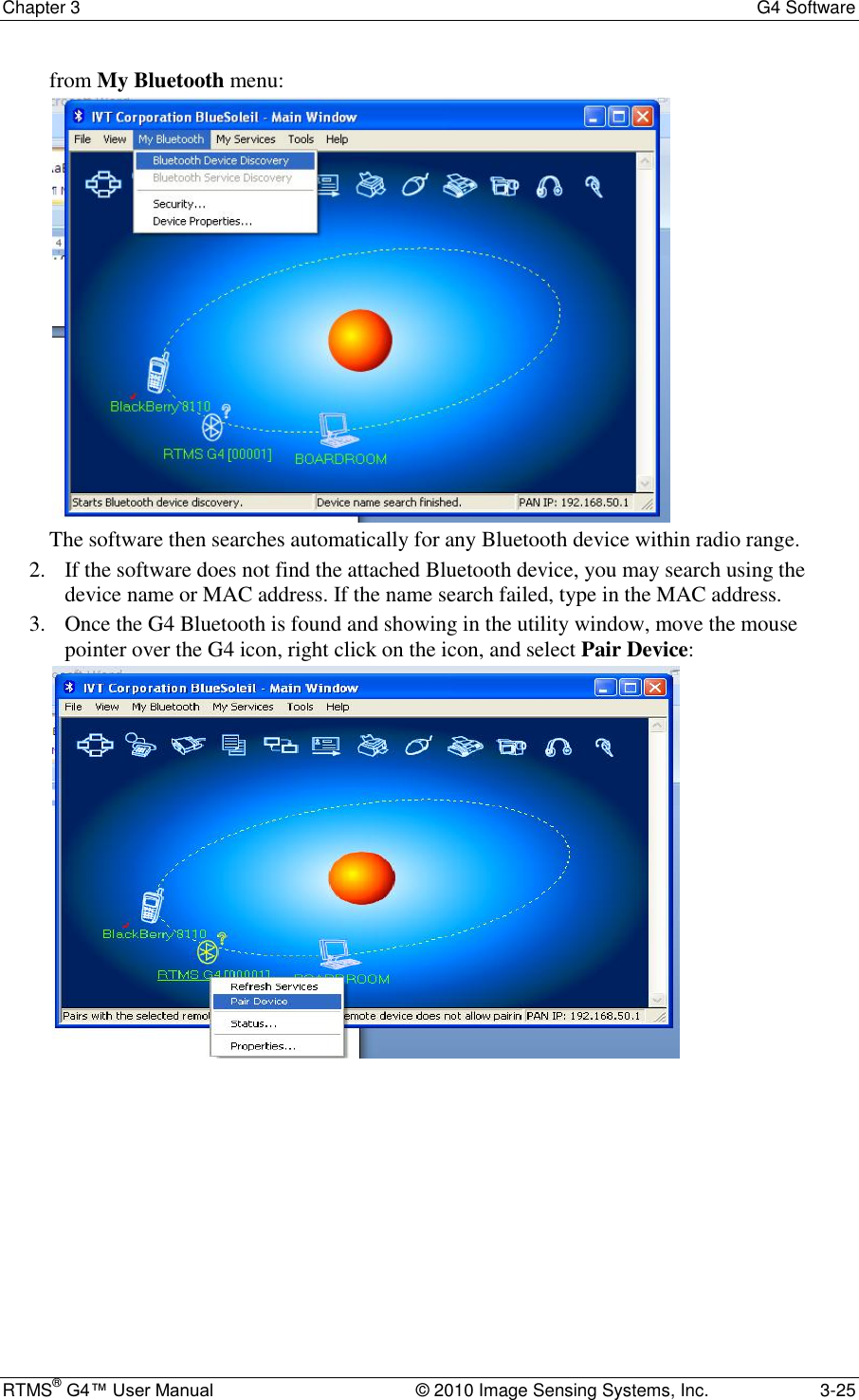
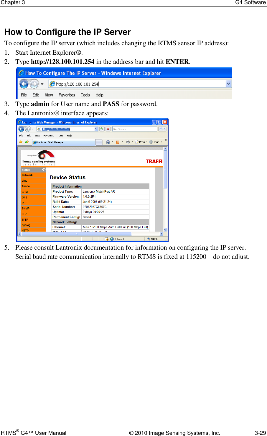
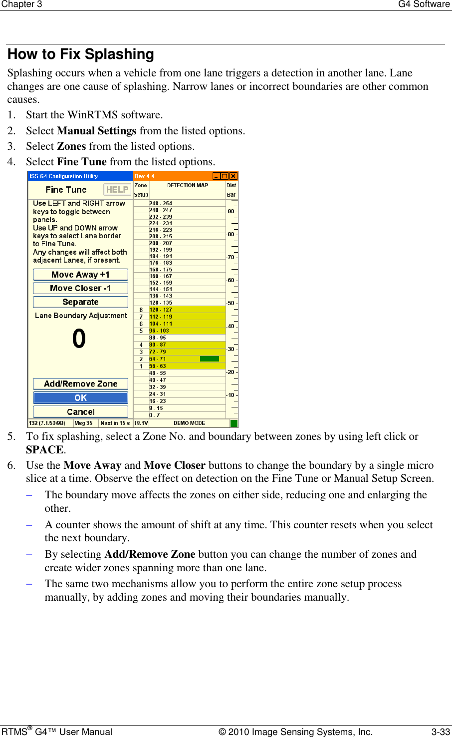
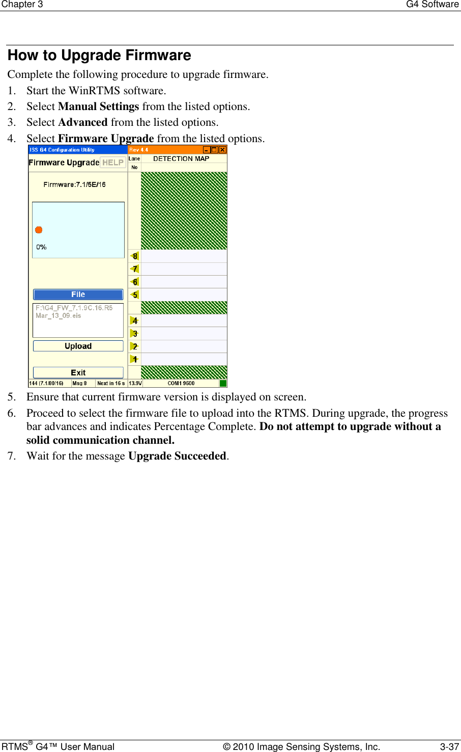
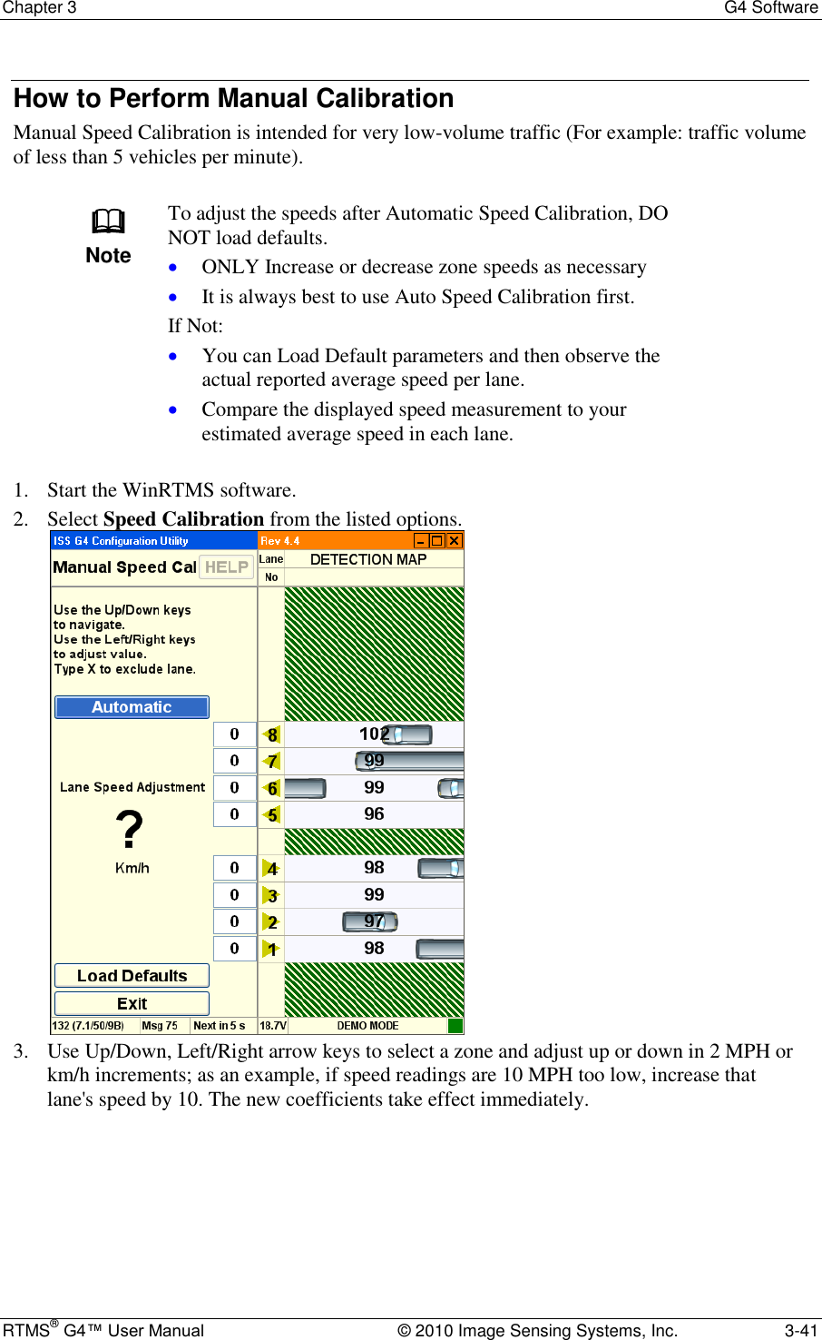
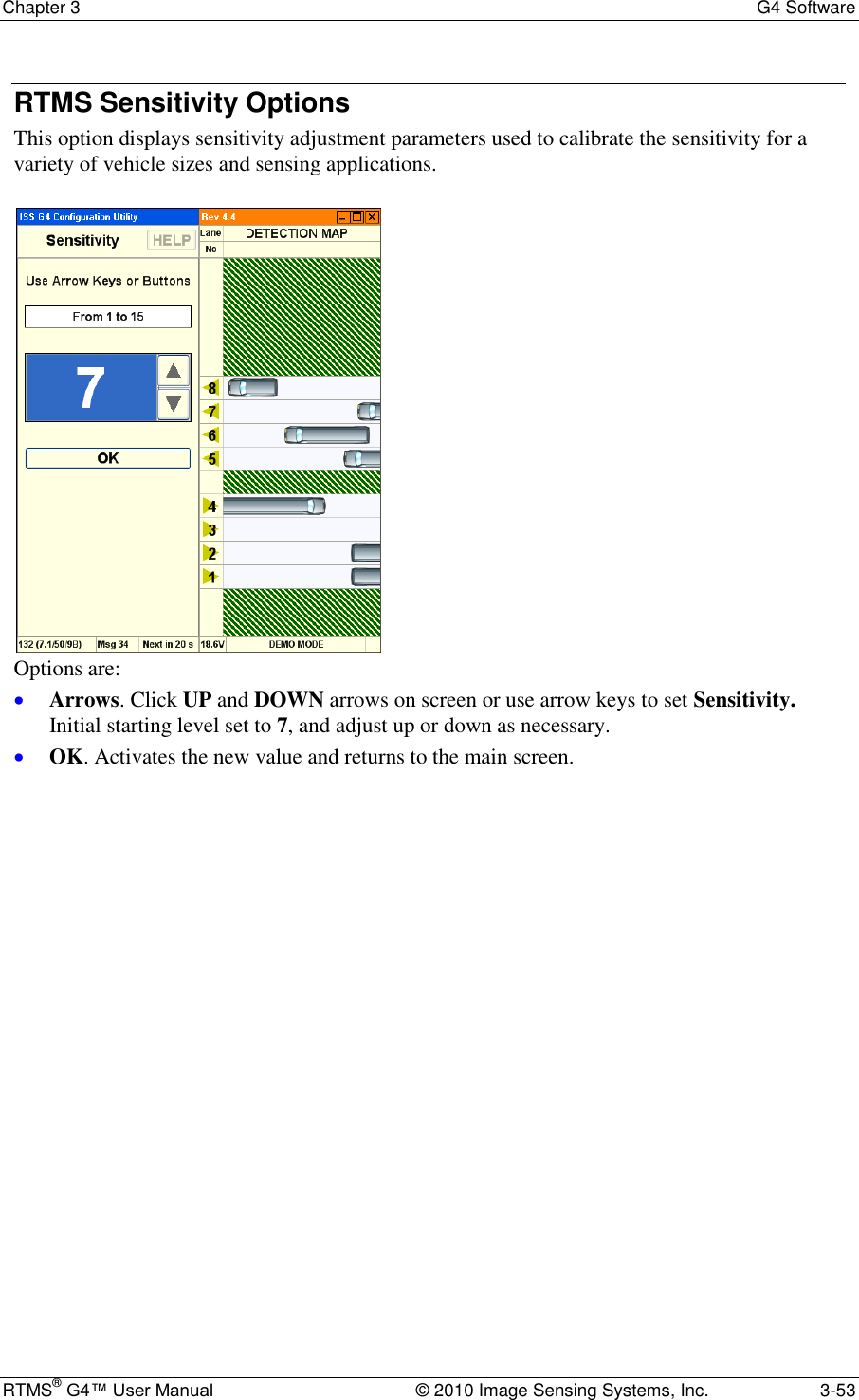
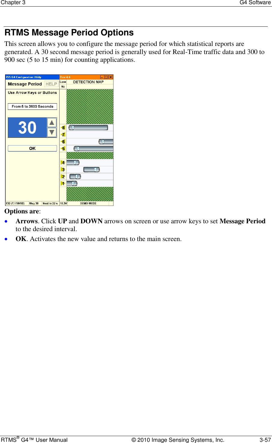
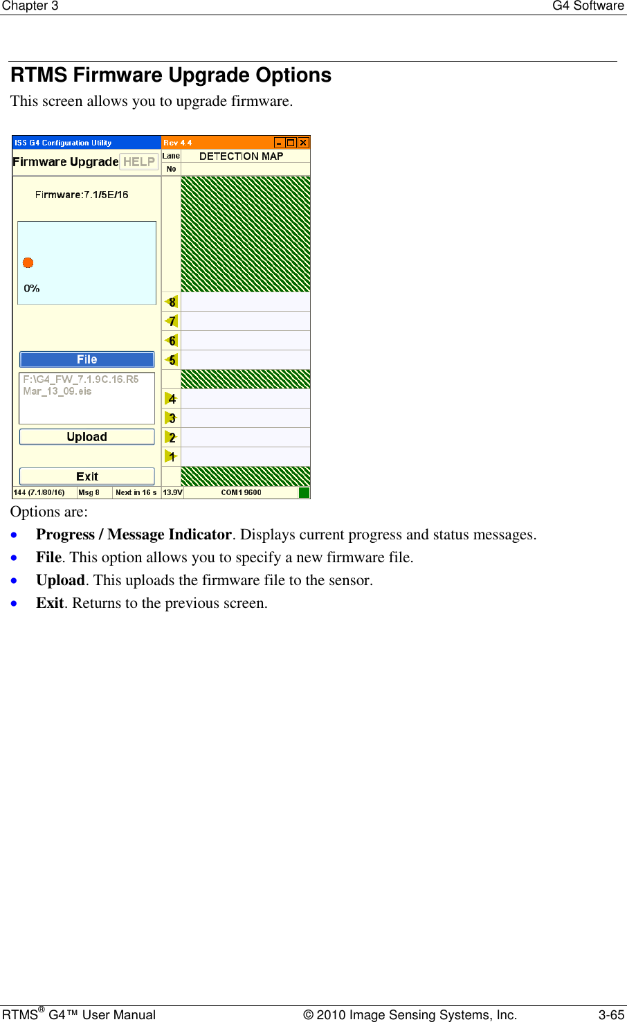
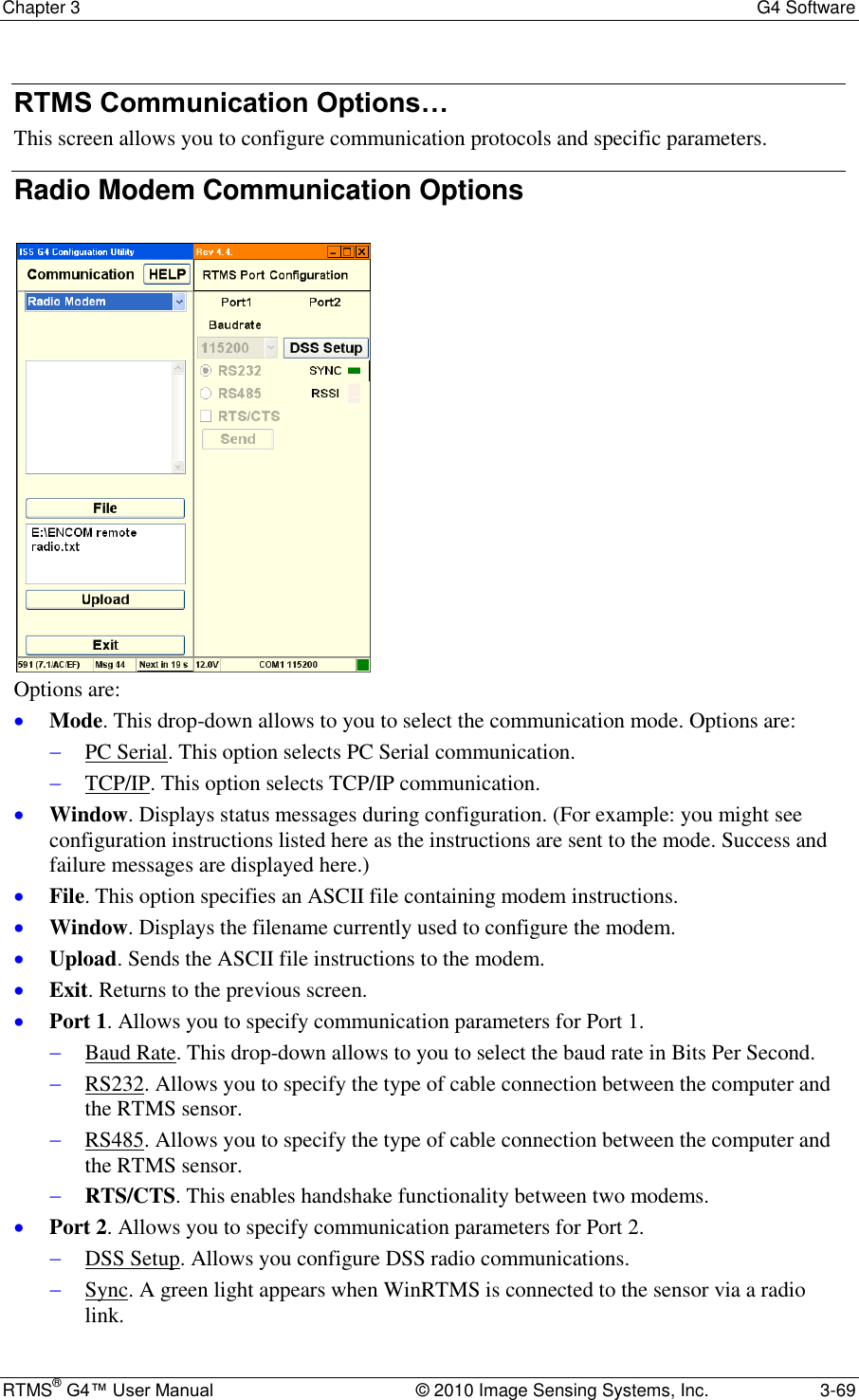
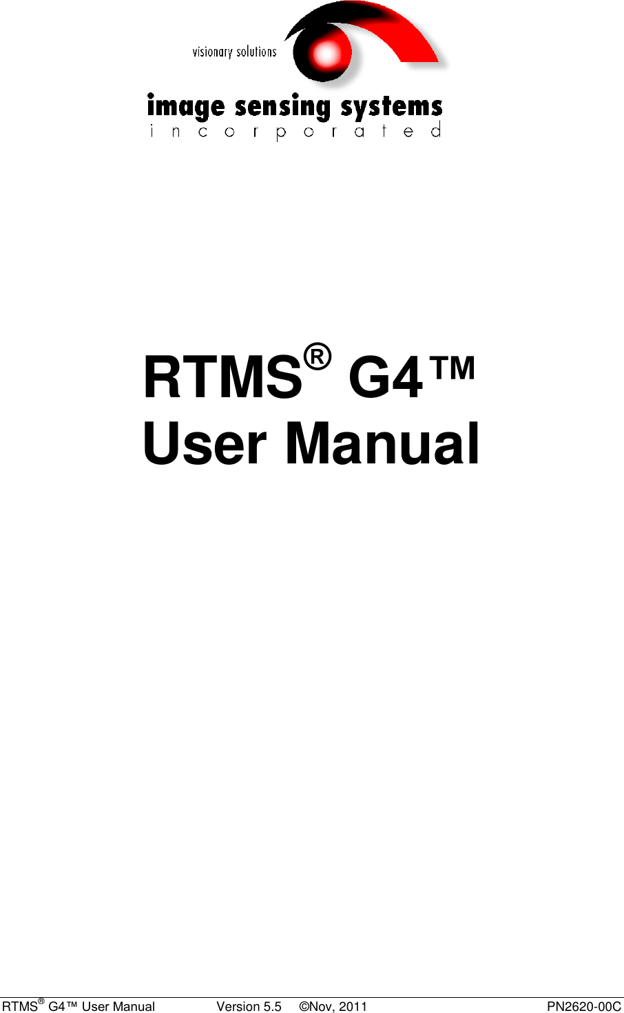
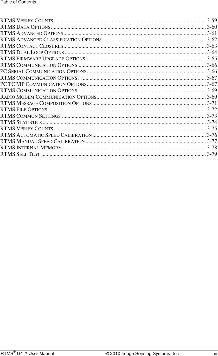
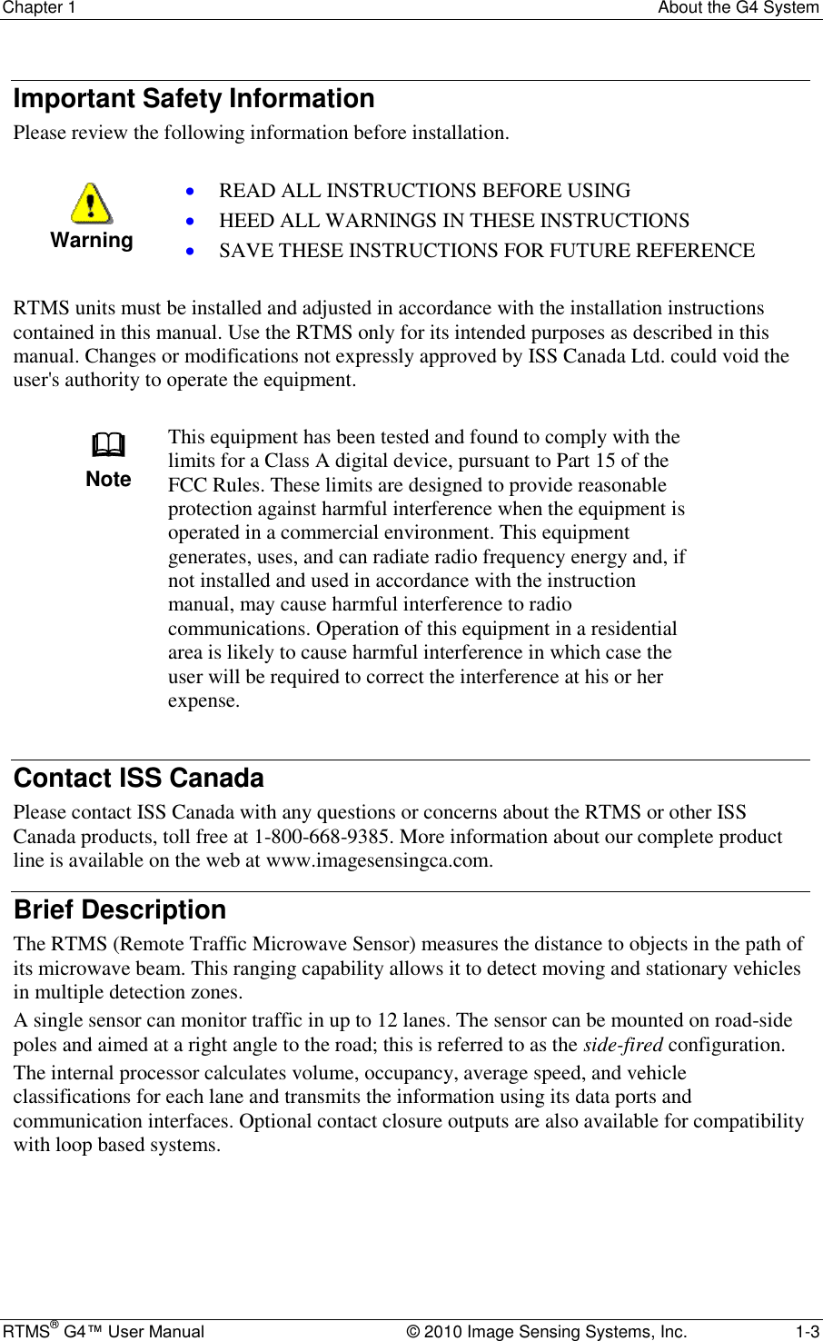
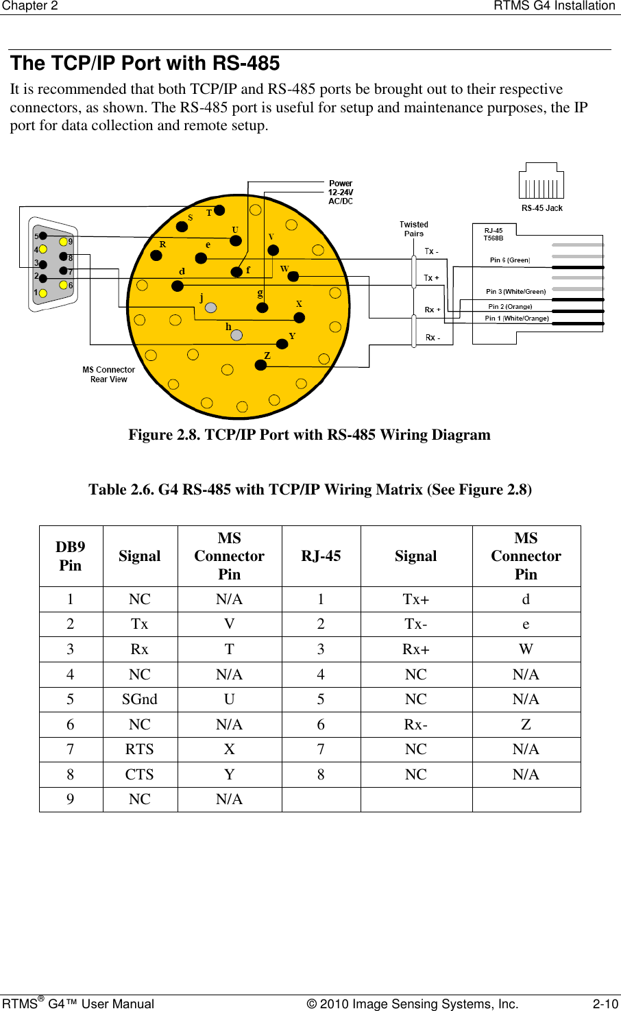
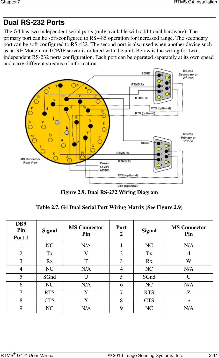
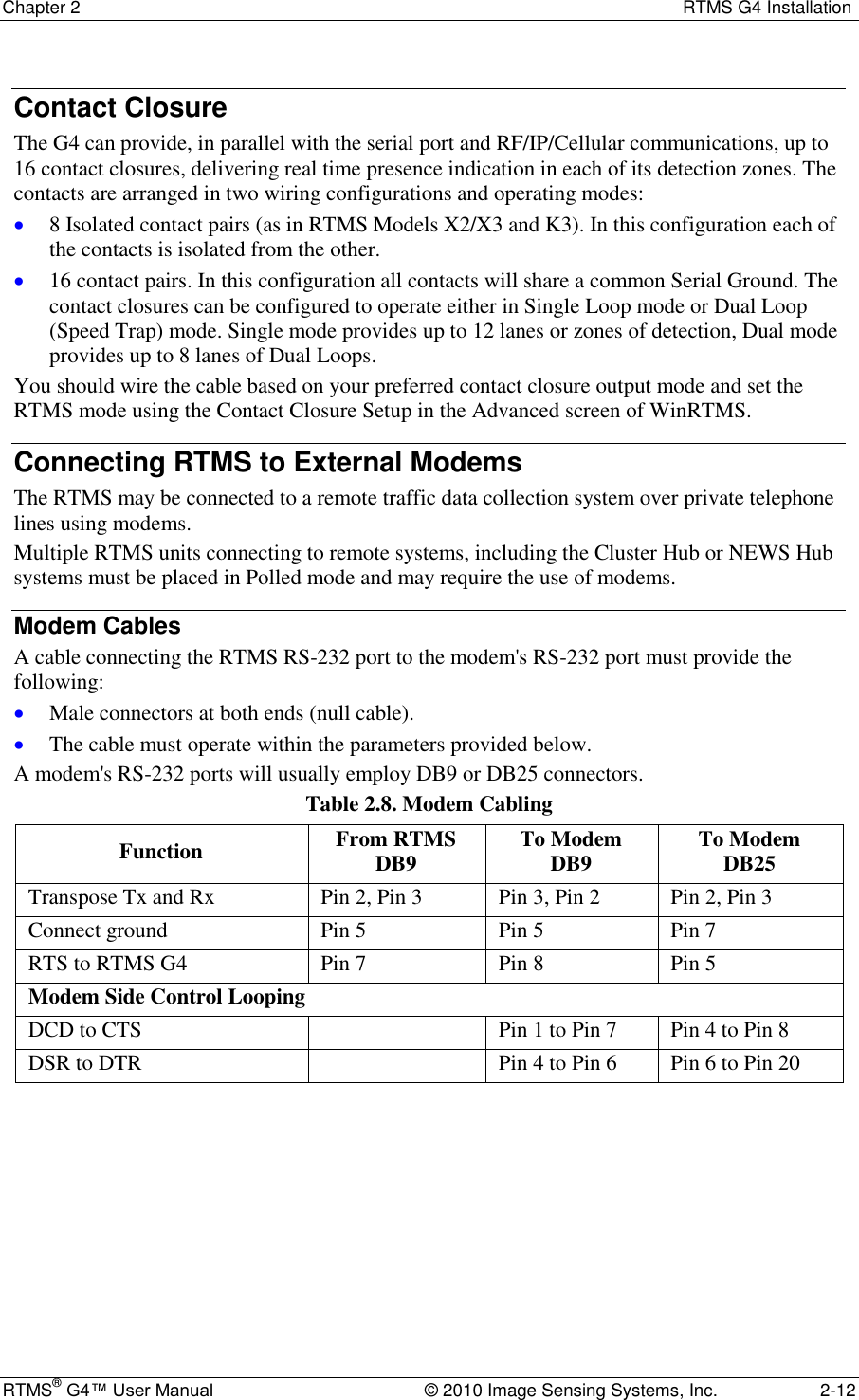
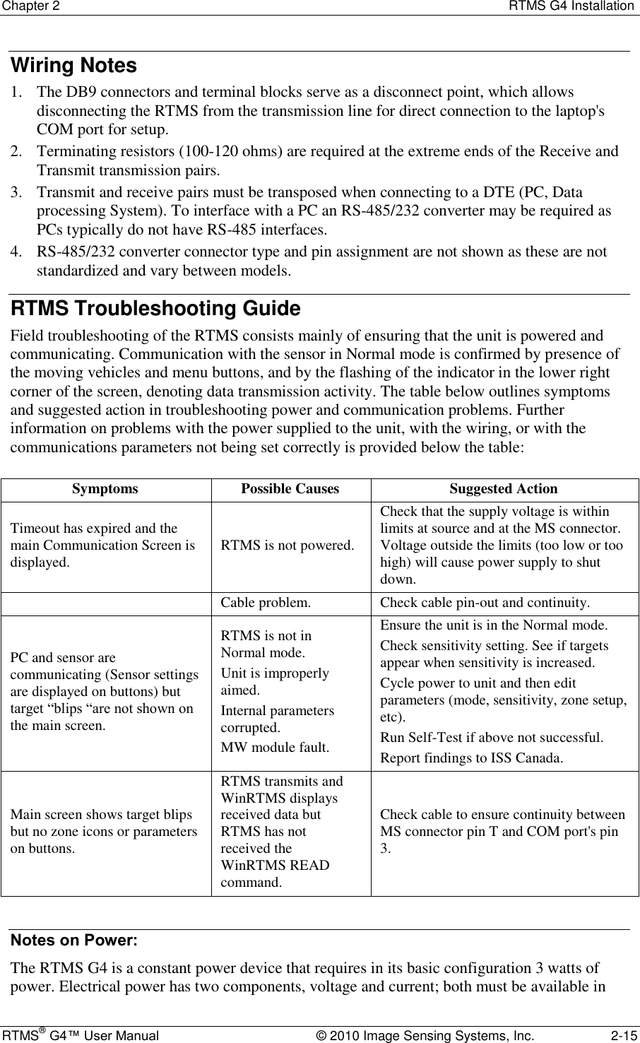
![Chapter 2 RTMS G4 Installation RTMS® G4™ User Manual © 2010 Image Sensing Systems, Inc. 2-8 The RS-485 Port Over short distances (30 ft [9 m]) the wiring diagram shown below is compatible with an RS-232 port. There is no standard pin configuration for RS-485 on a DB9 connector. The wiring diagram shown will connect directly to a RS-232 configured DB9 without the need for an RS-232/RS-485 converter. A disconnect point is recommended to allow the RTMS to be detached from the transmission line without disruption of communications with other sensors on the line. See Connecting RTMS to External Modems for details. Figure 2.6. RS-485 Wiring Diagram Table 2.4. G4 RS-485 Wiring Matrix (See Figure 2.6) DB9 Pin Signal MS Connector Pin 1 NC N/A 2 Tx- V 3 Rx- T 4 NC N/A 5 SGnd U 6 NC N/A 7 Tx+ X 8 Rx+ Y 9 NC N/A](https://usermanual.wiki/Image-Sensing-Systems/RTMS-K4S/User-Guide-1591677-Page-20.png)
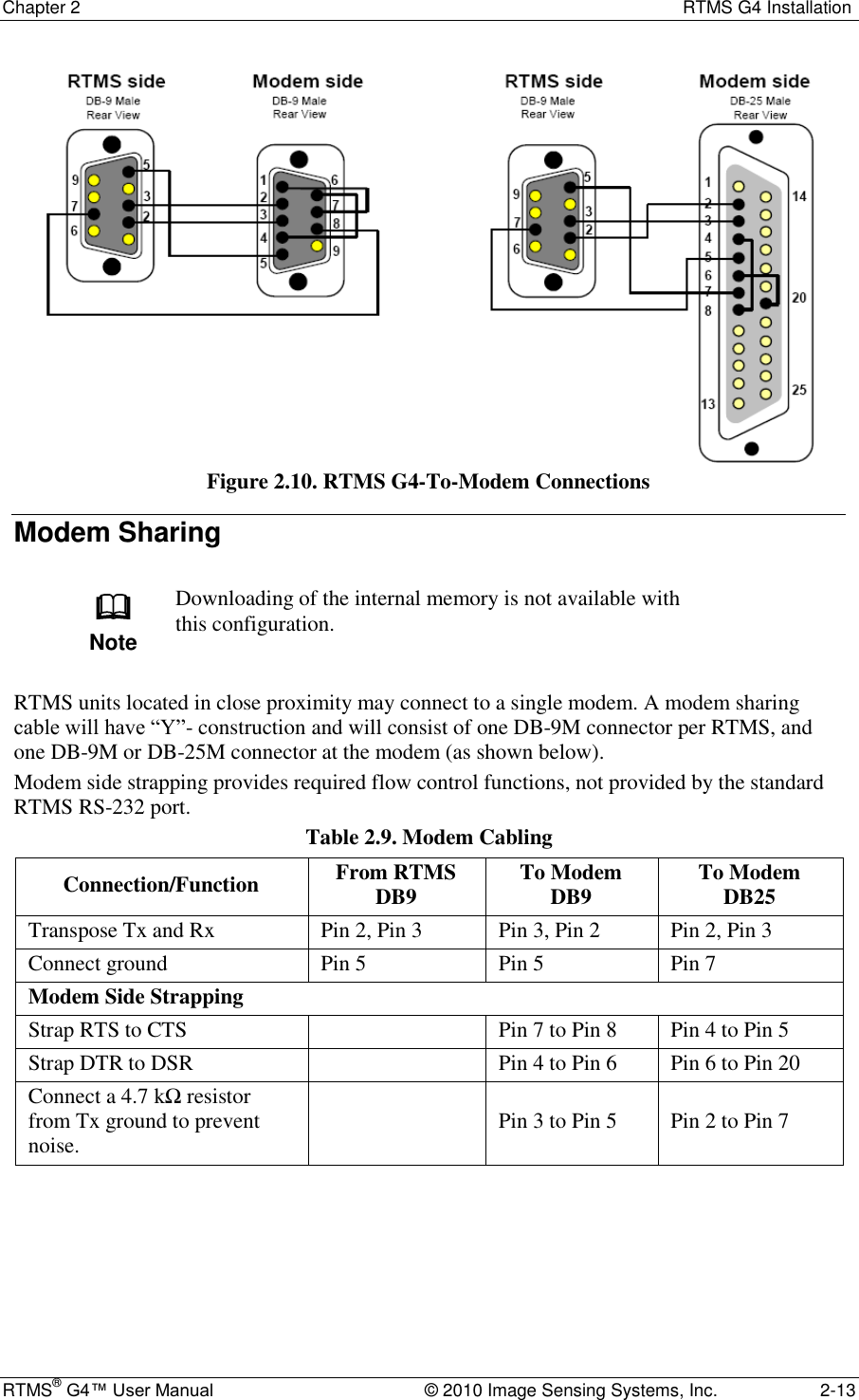
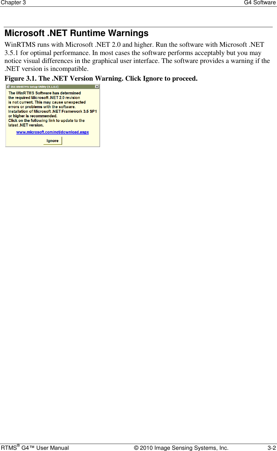
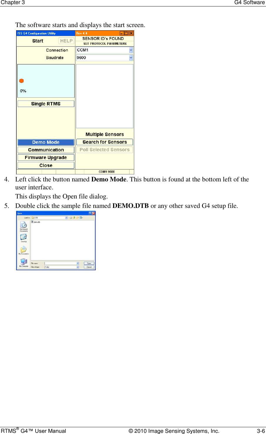
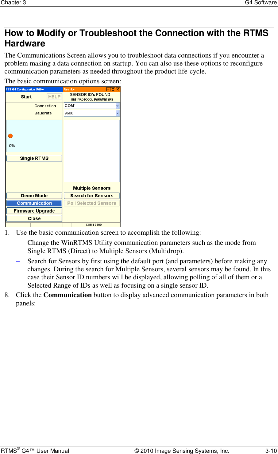
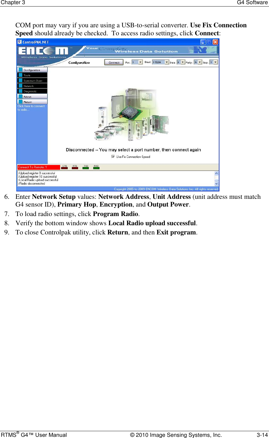
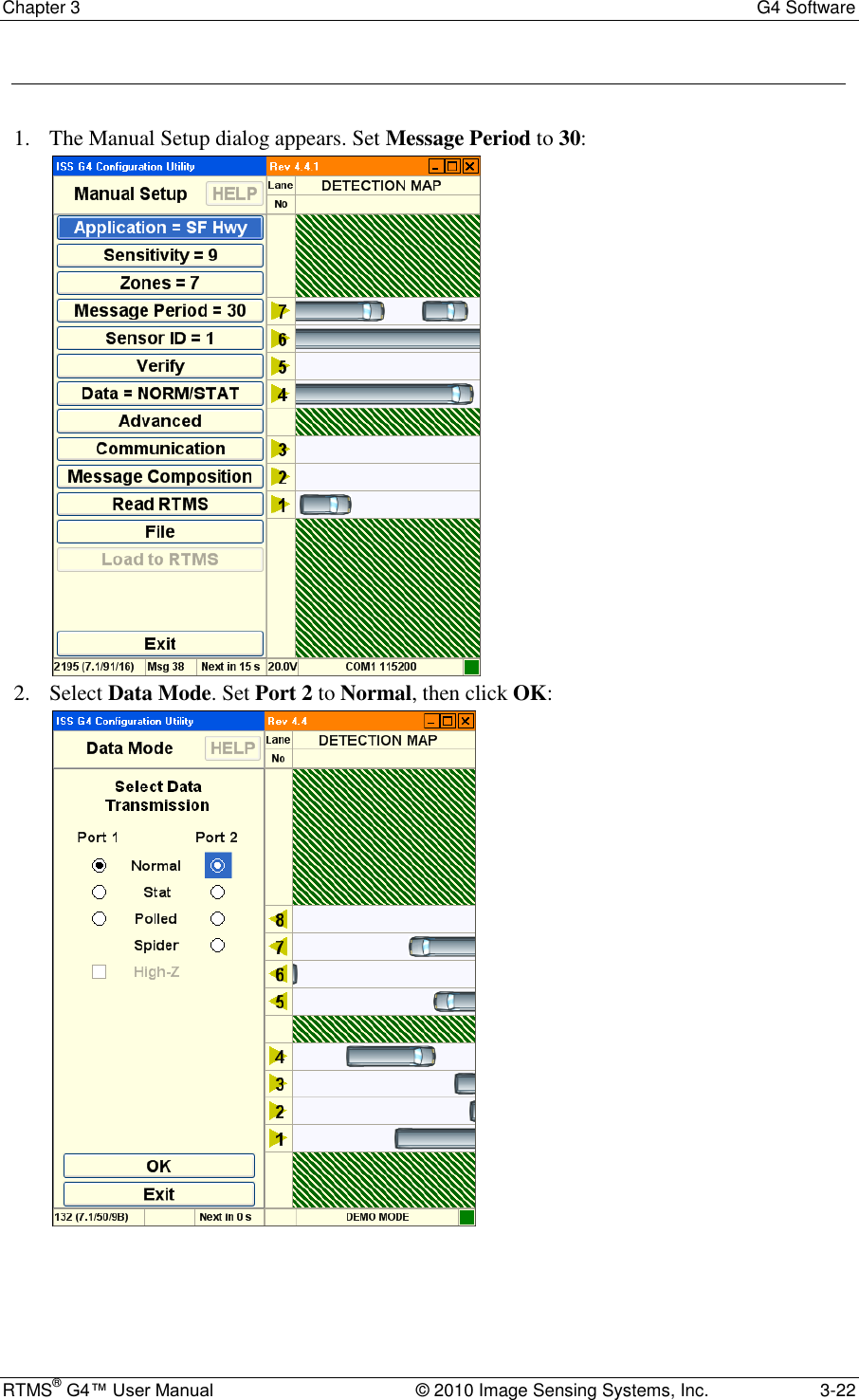
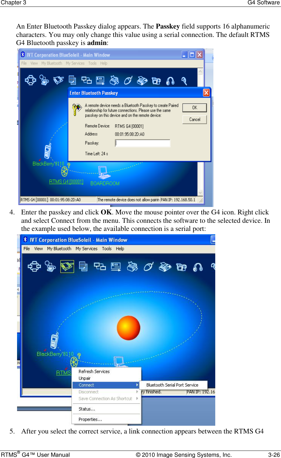
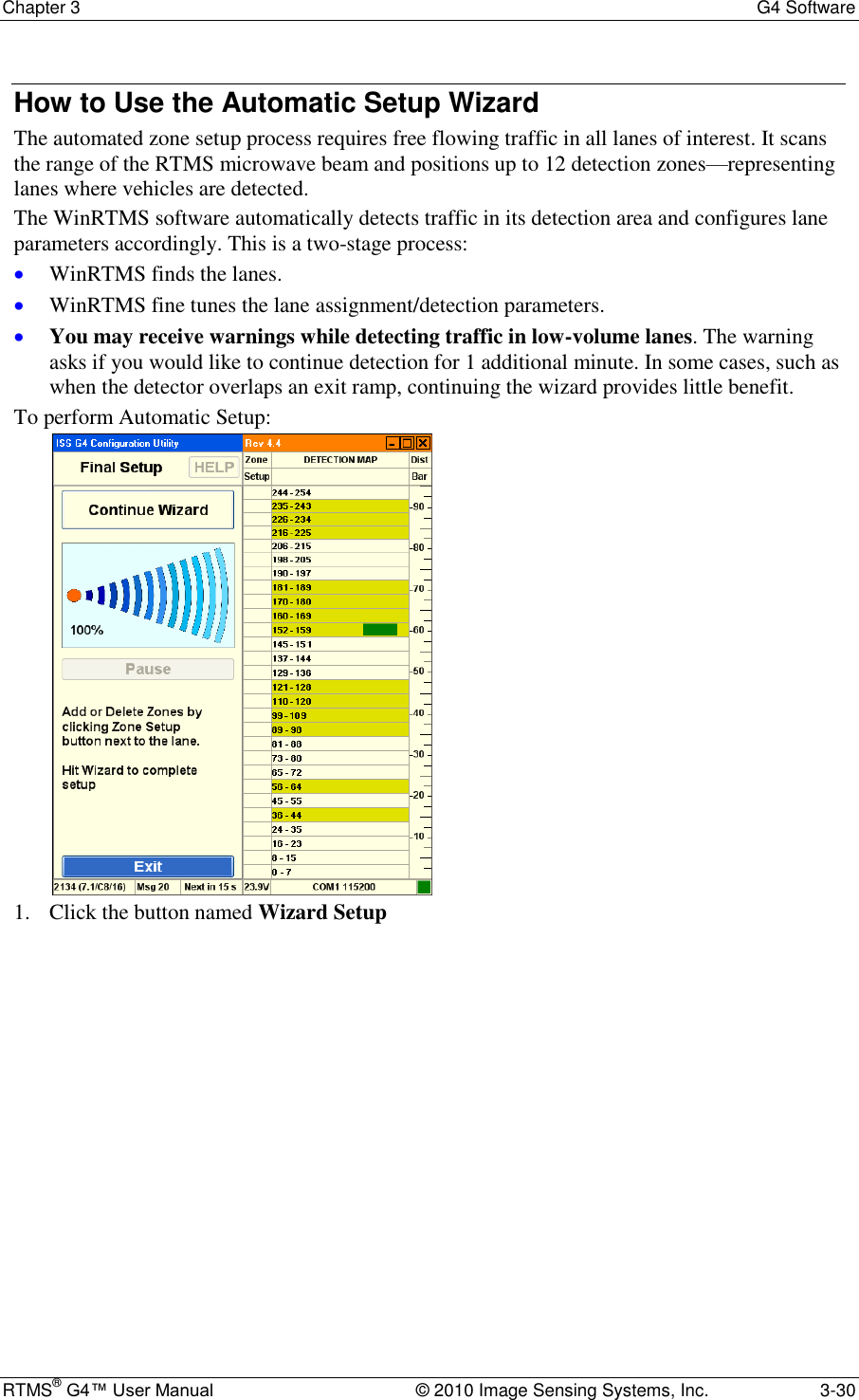
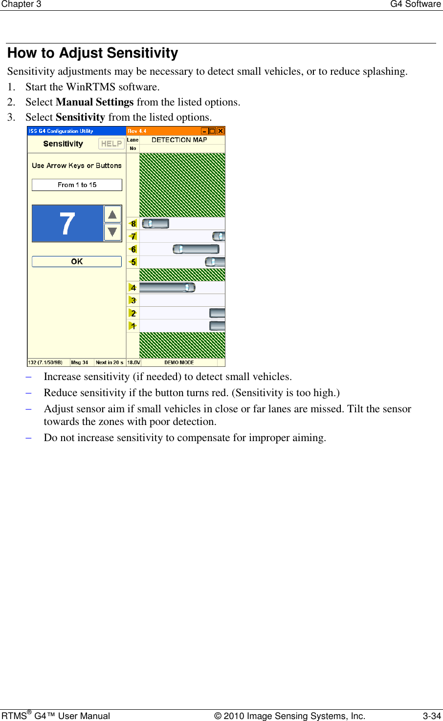
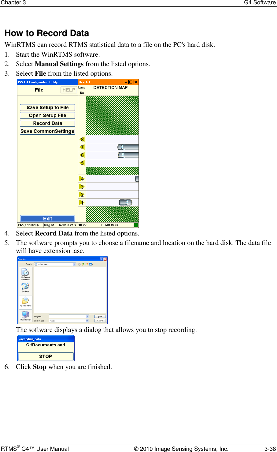
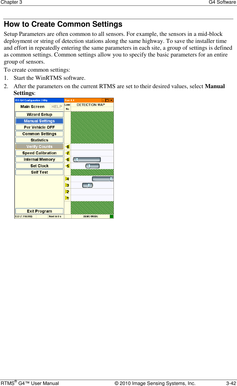
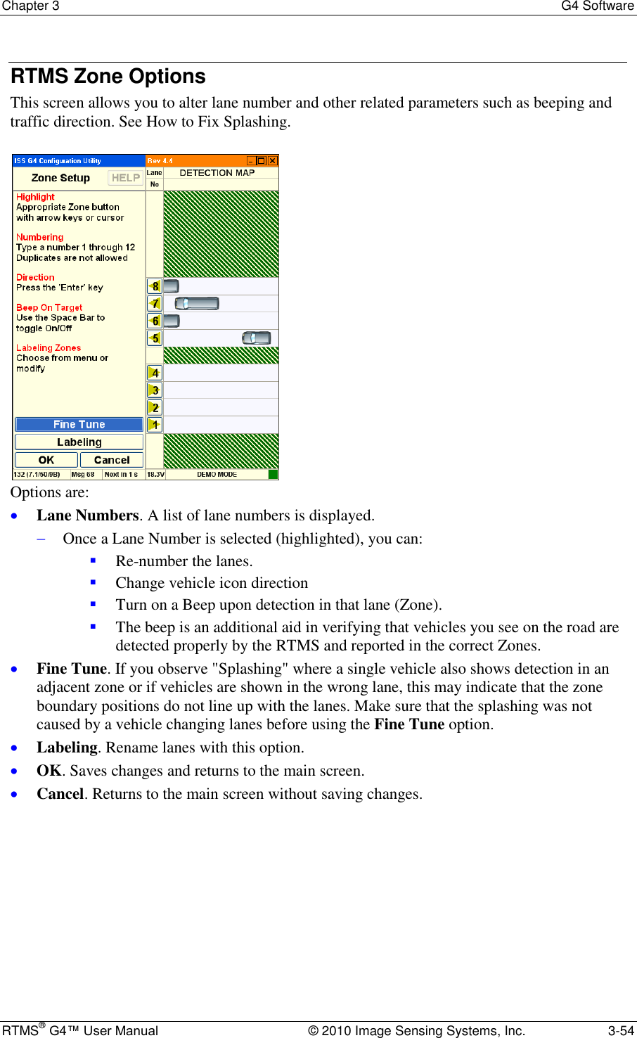
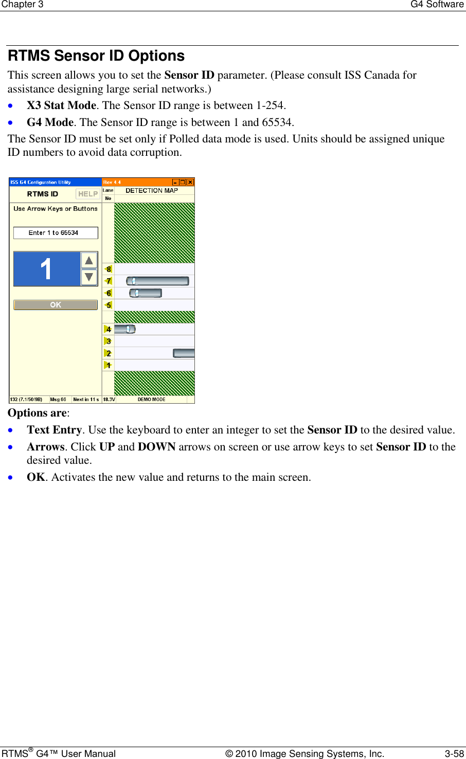
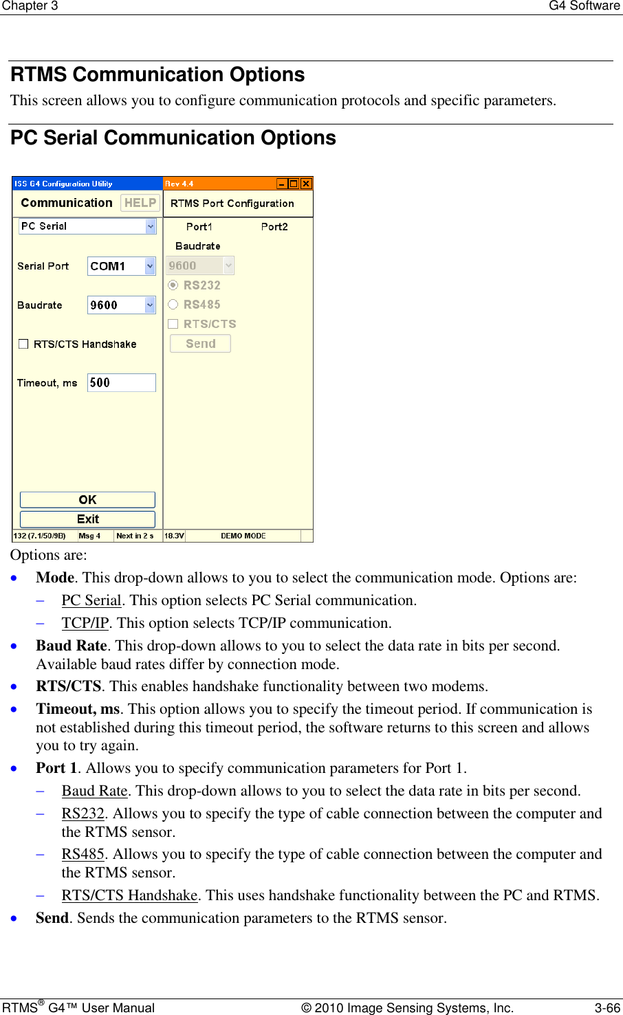
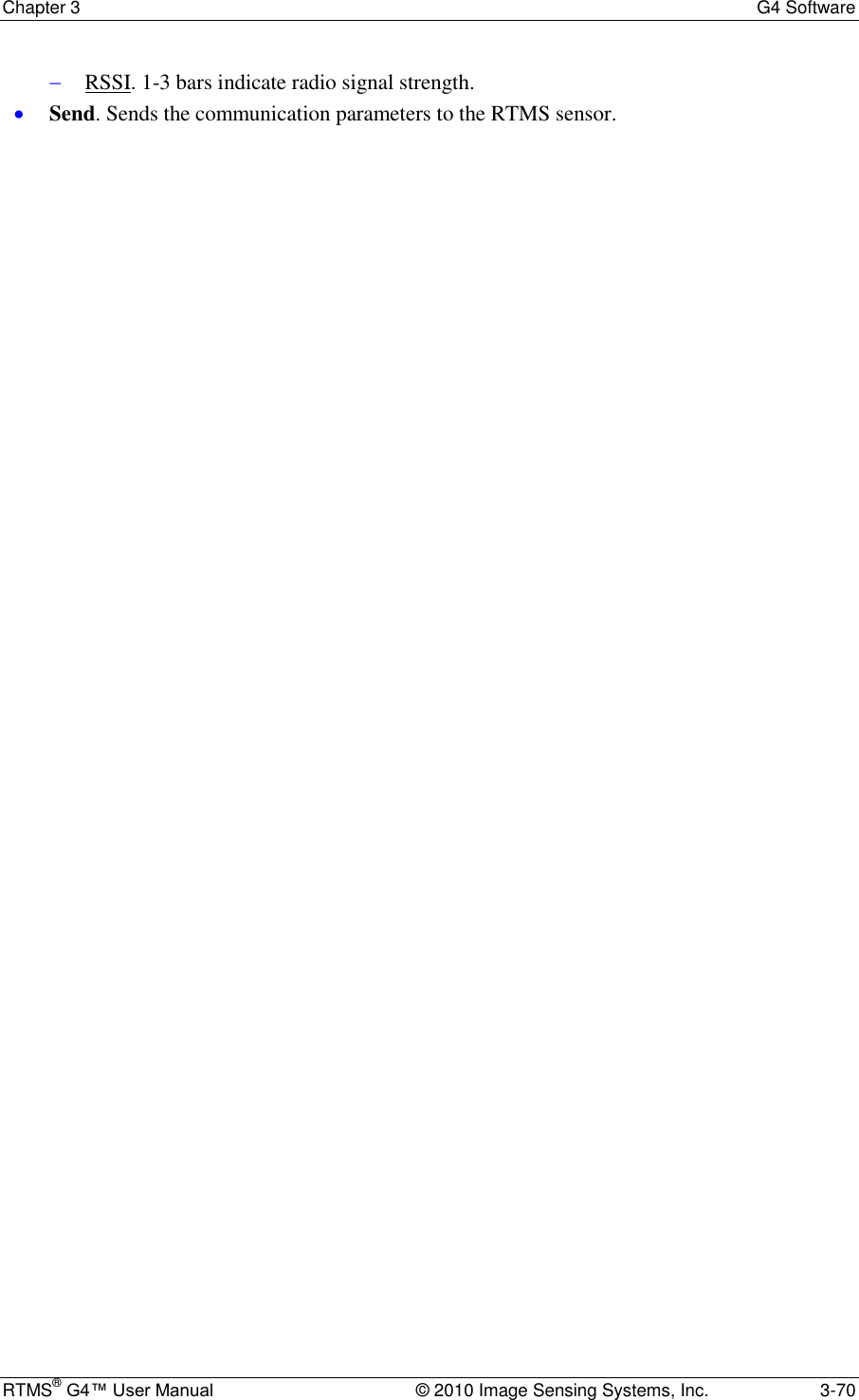
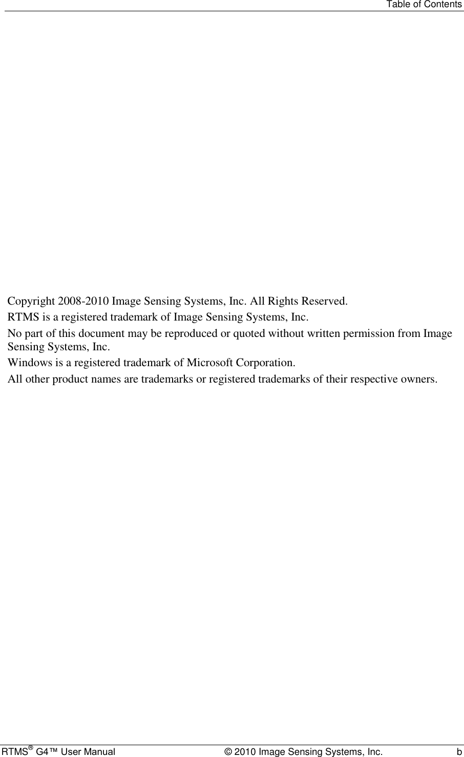
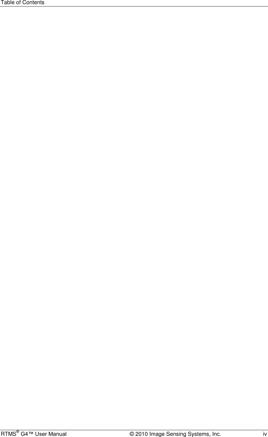
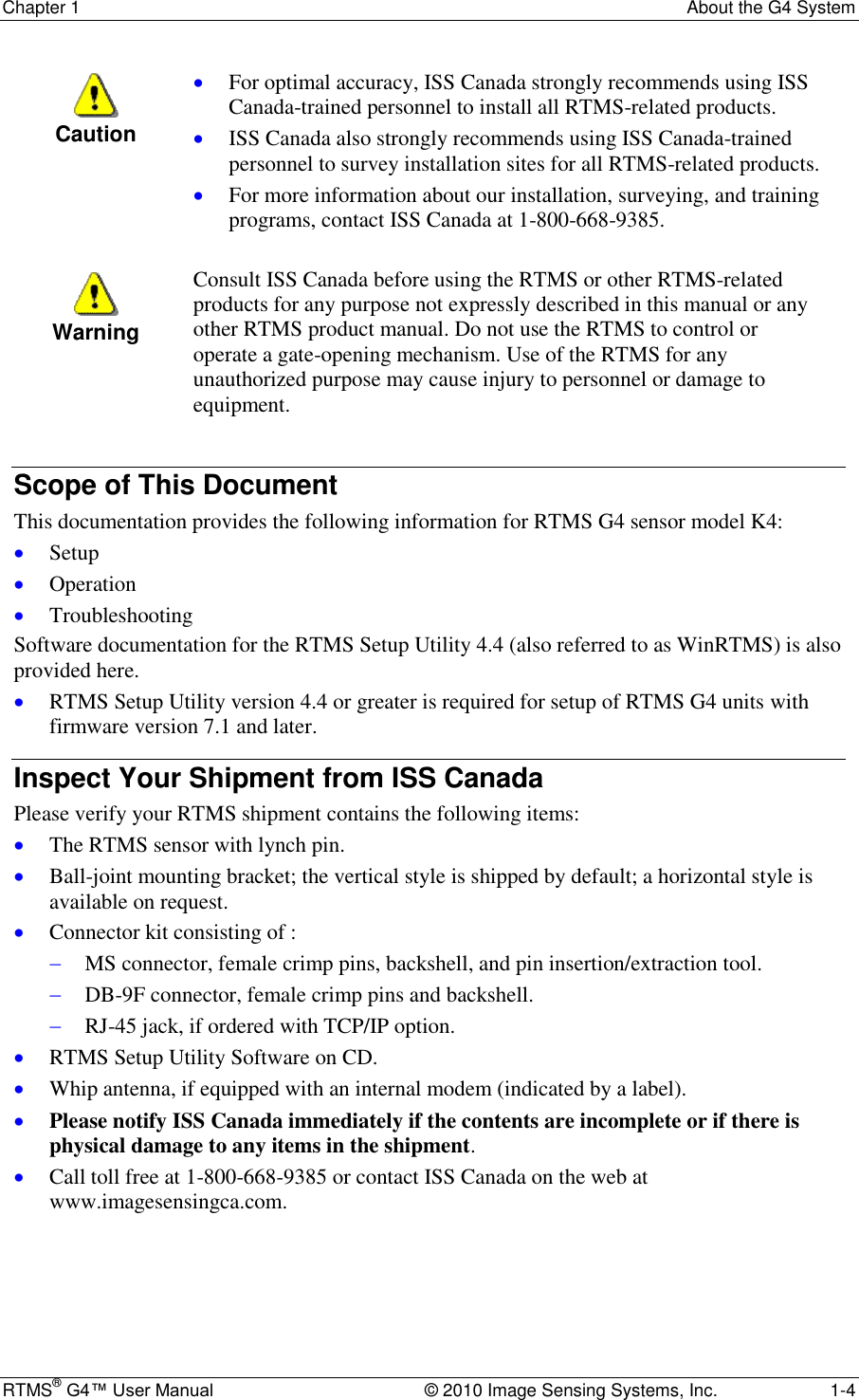
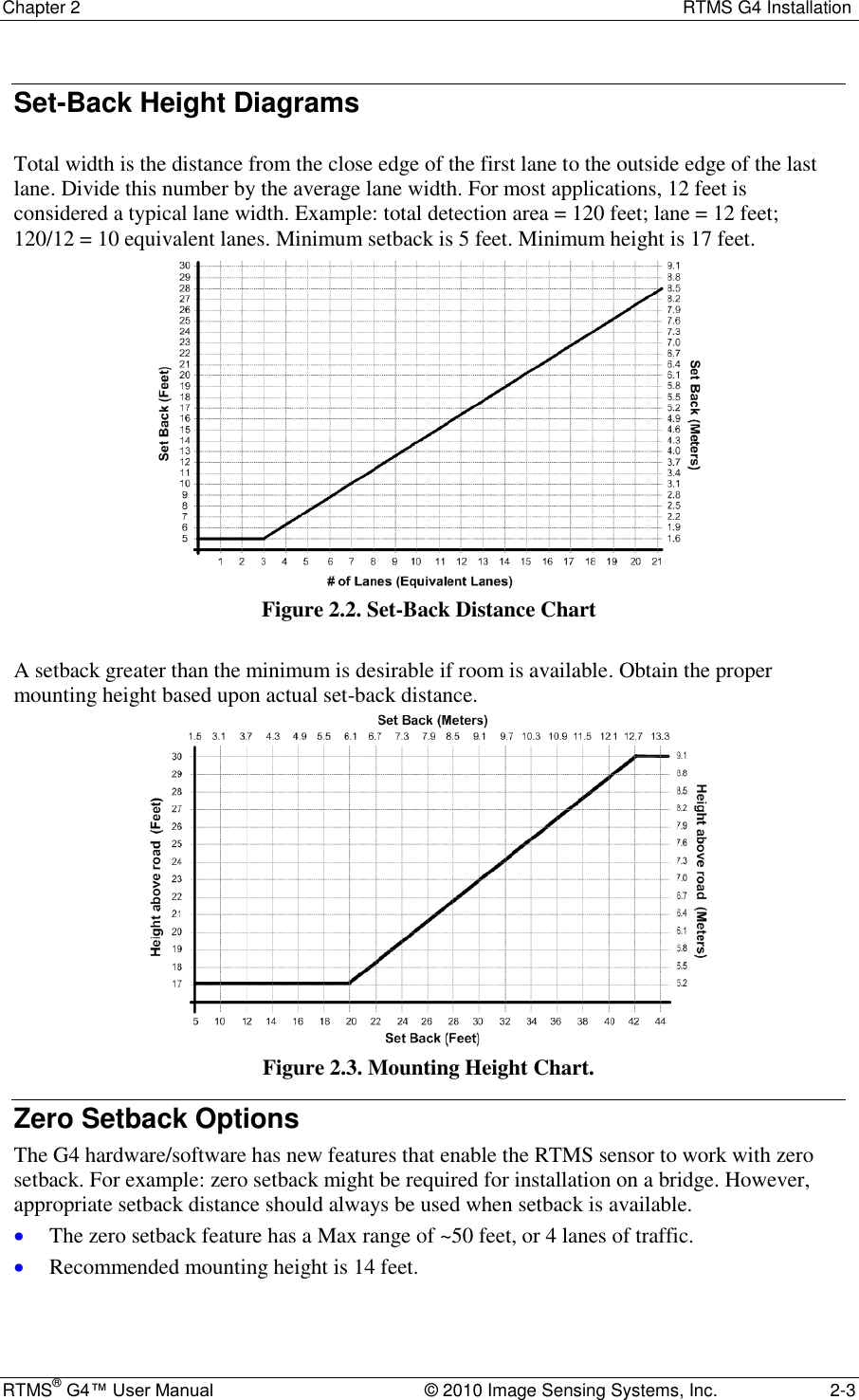
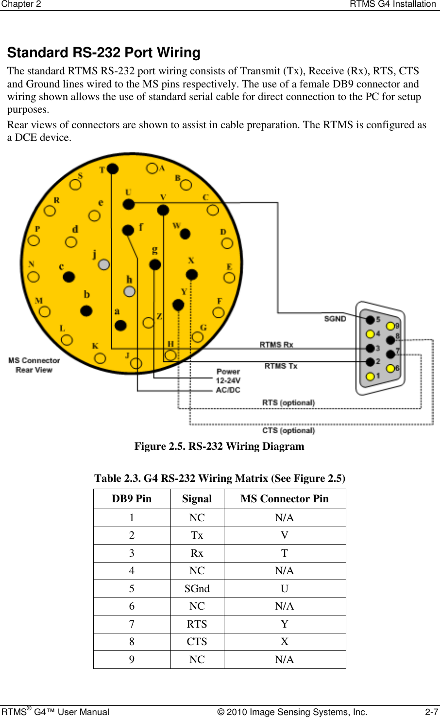
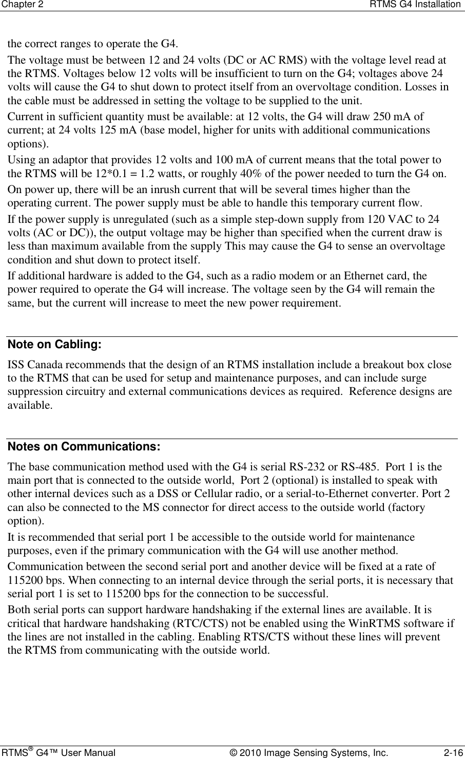
![Chapter 2 RTMS G4 Installation RTMS® G4™ User Manual © 2010 Image Sensing Systems, Inc. 2-14 Figure 2.11. Modem sharing "Y" cables. (No Memory Download.) RS-485 Multi-Drop The RS-485 setting of the G4 Serial Port allows up to 32 RTMS units to be employed on the same serial bus over distances up to 4000 feet [1200 m]. The diagram Figure 2-12 shows the use of a 4-Wire line. The use of a half-duplex 2-Wire line is feasible but it is suitable for data collection only. Consult RS-485/422 Application Guides for details on wiring solutions for your project. Figure 2.12. RS-485 Multi-Drop Wiring](https://usermanual.wiki/Image-Sensing-Systems/RTMS-K4S/User-Guide-1591677-Page-26.png)
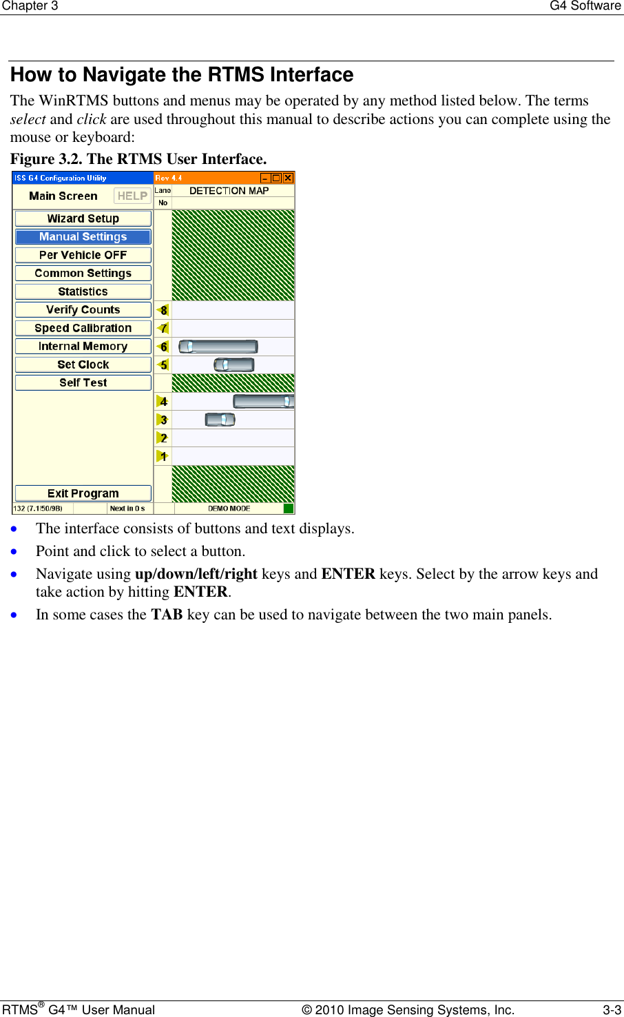
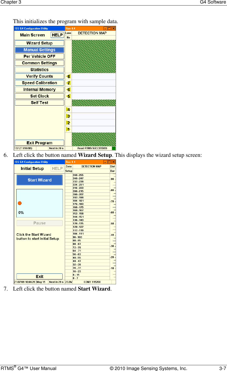
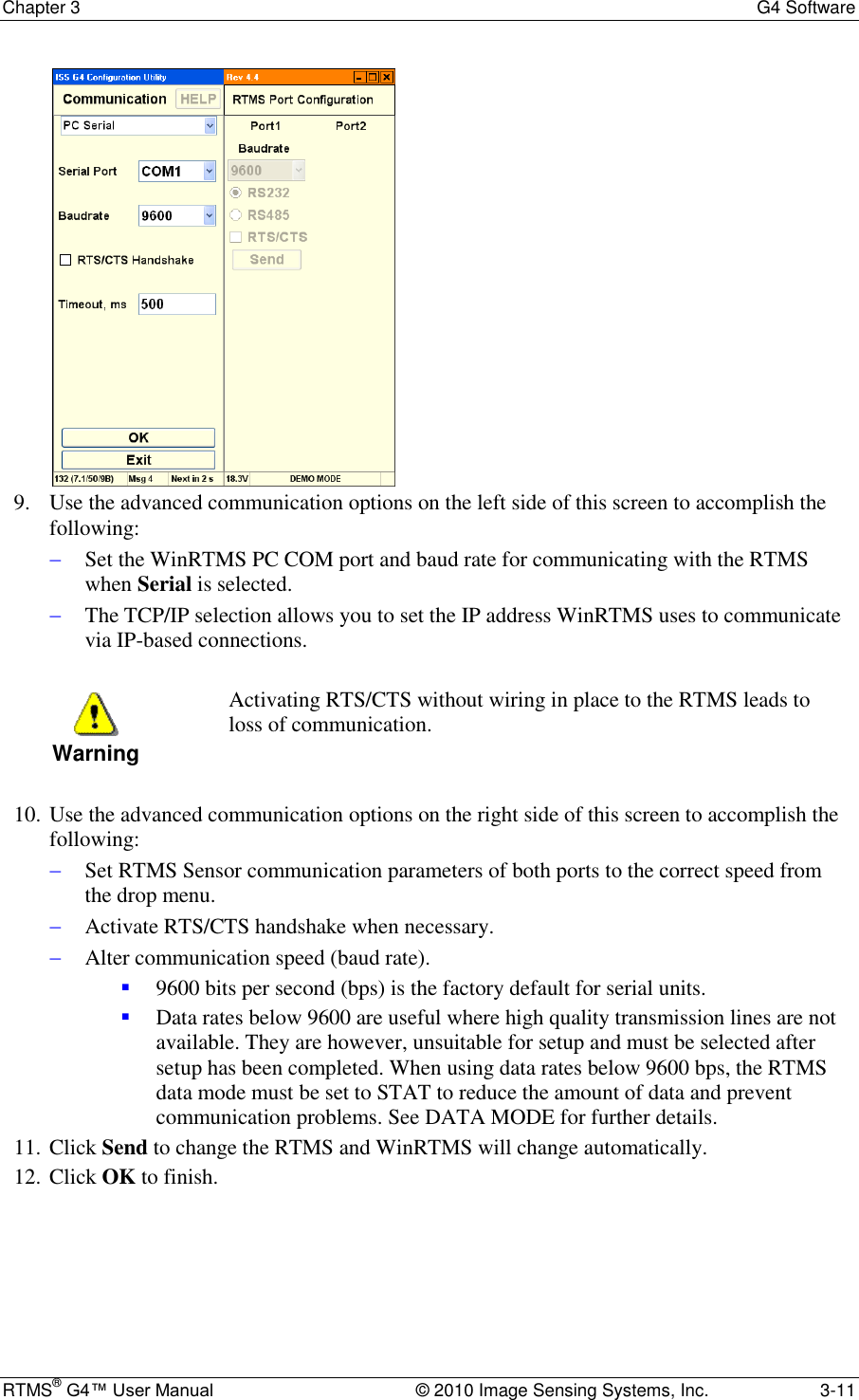
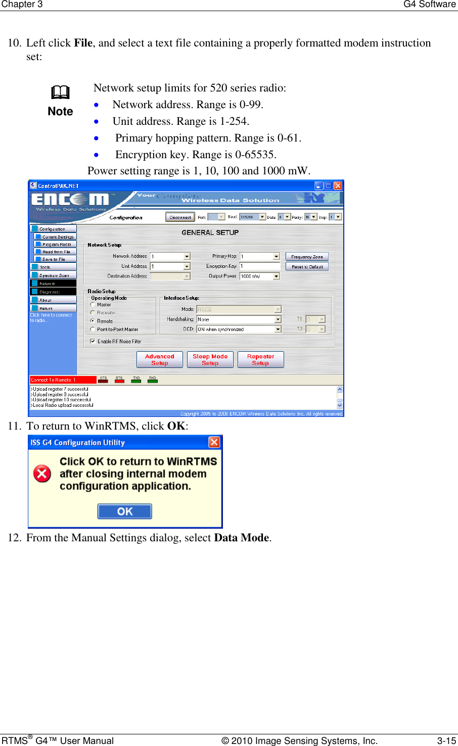
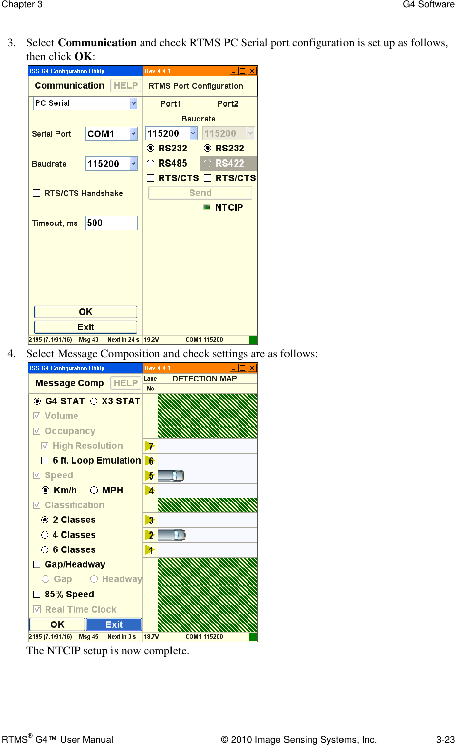
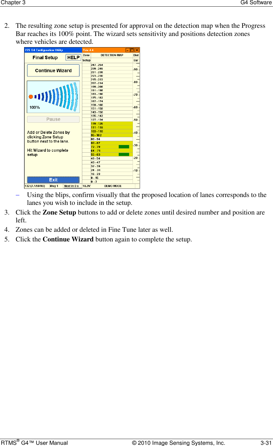
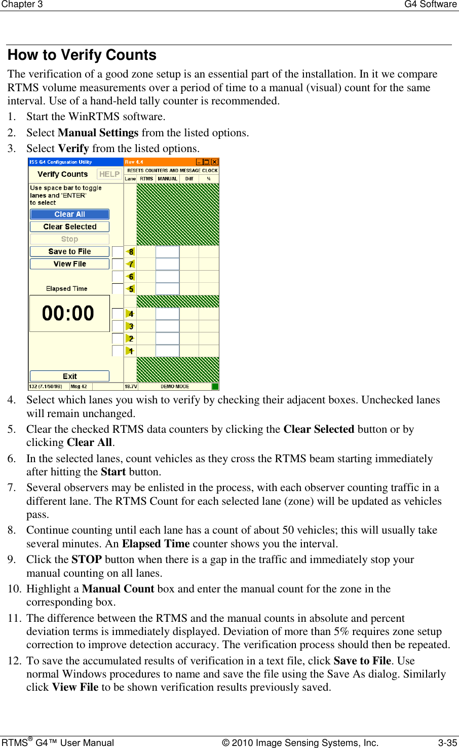
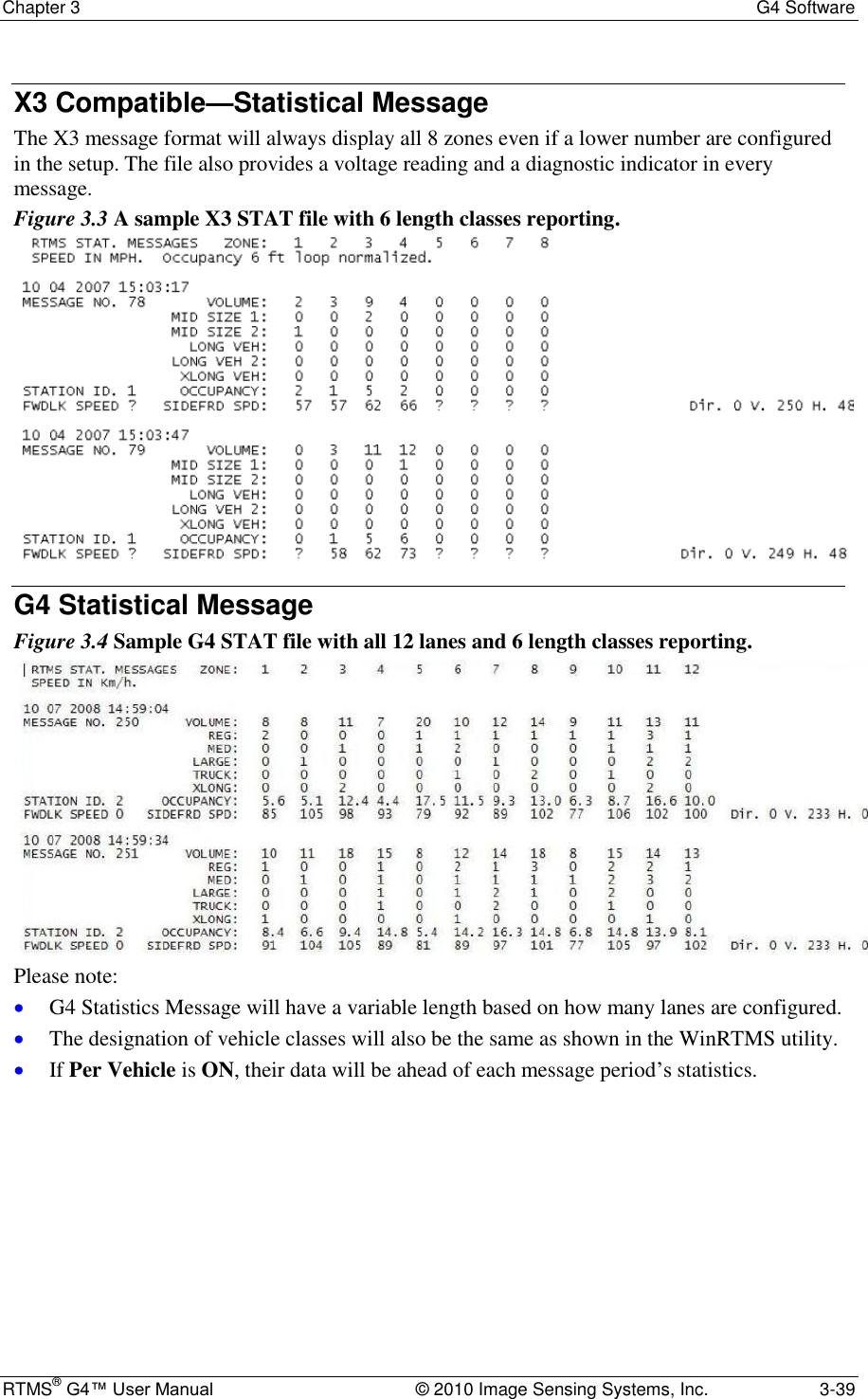
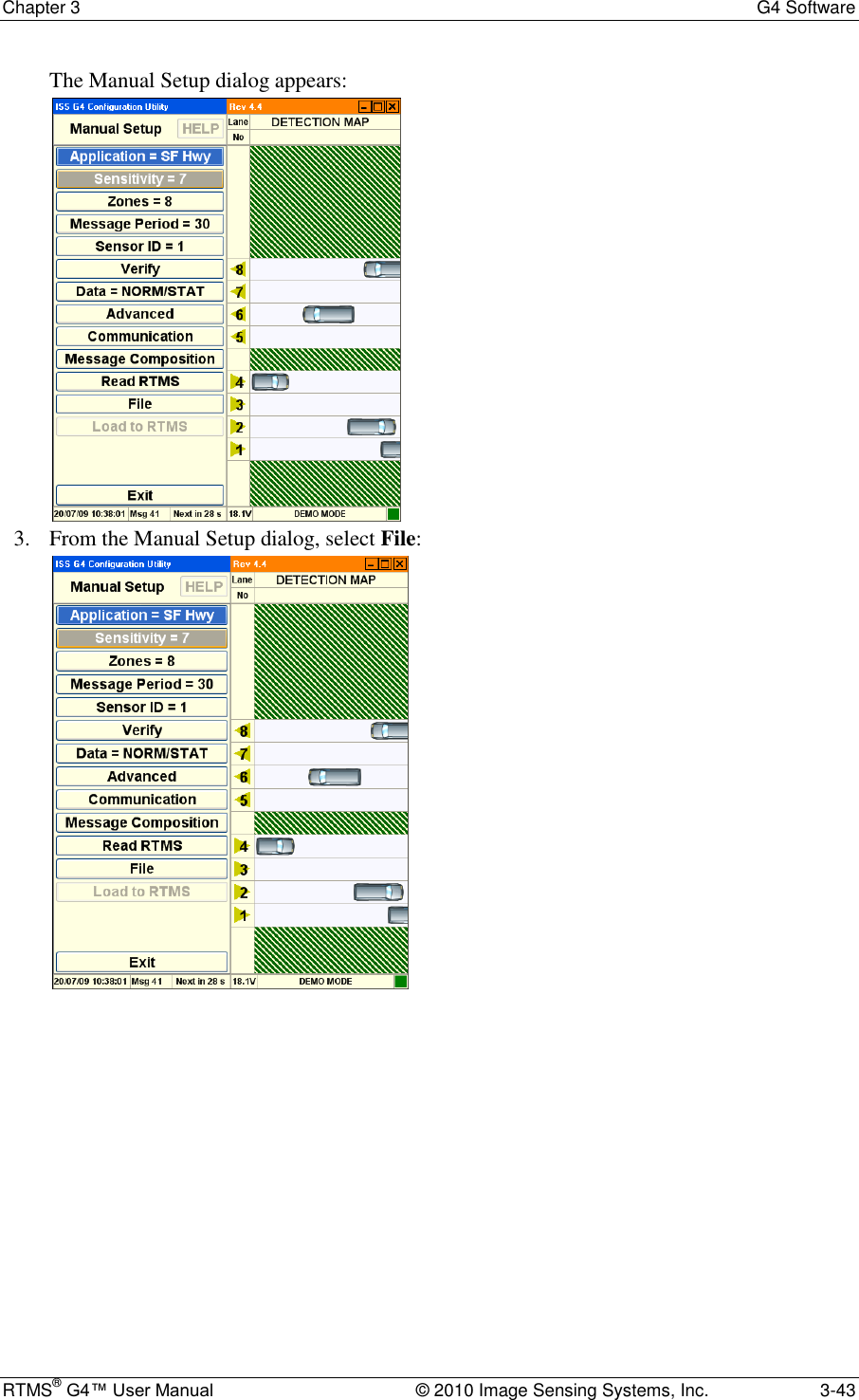
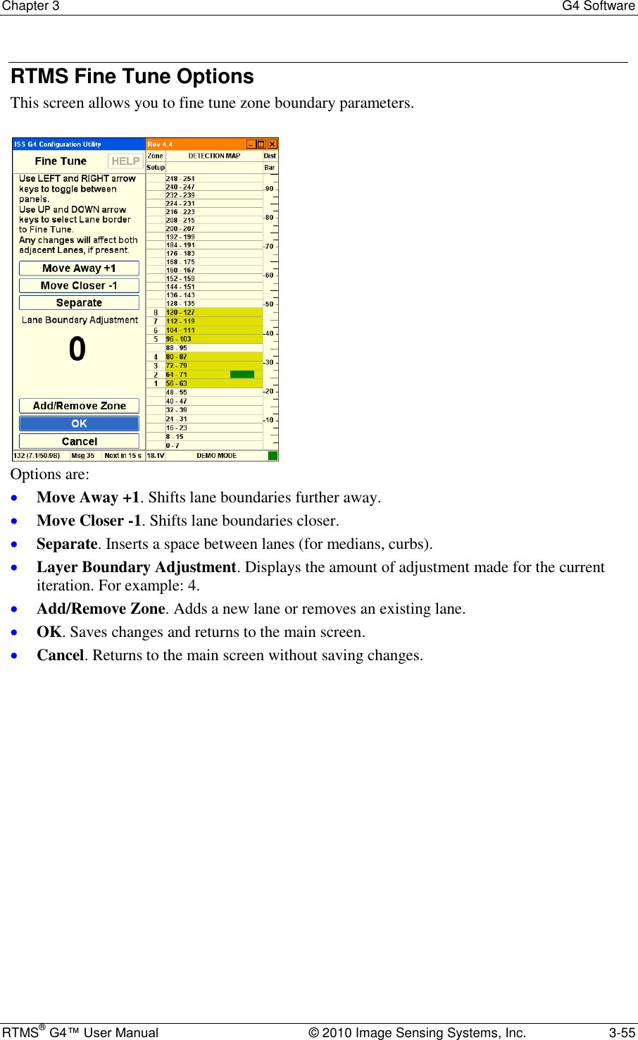
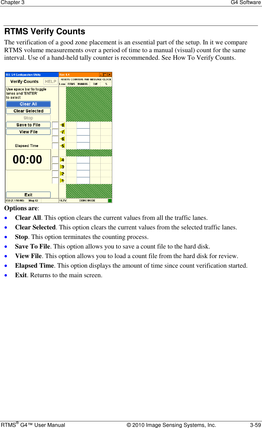
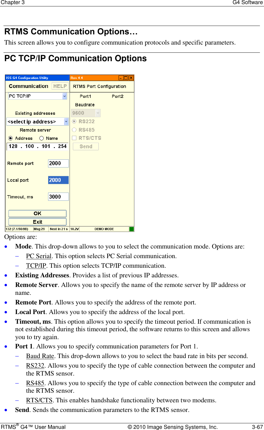
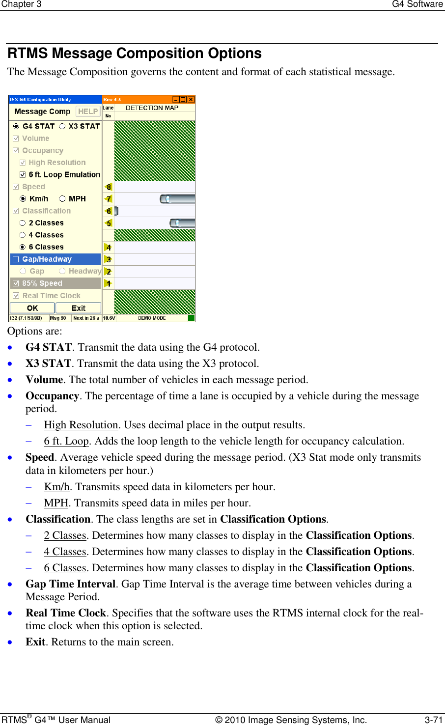
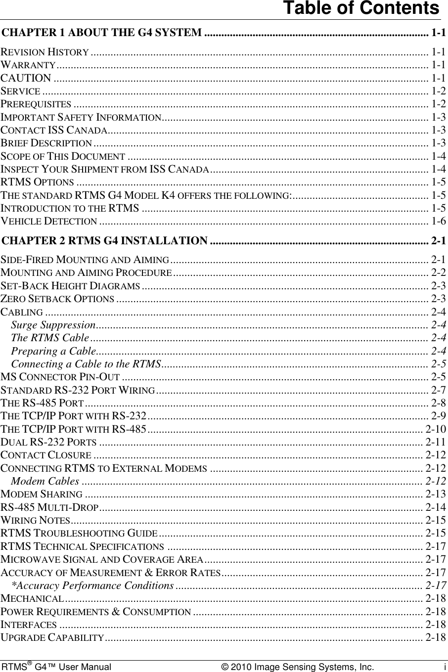
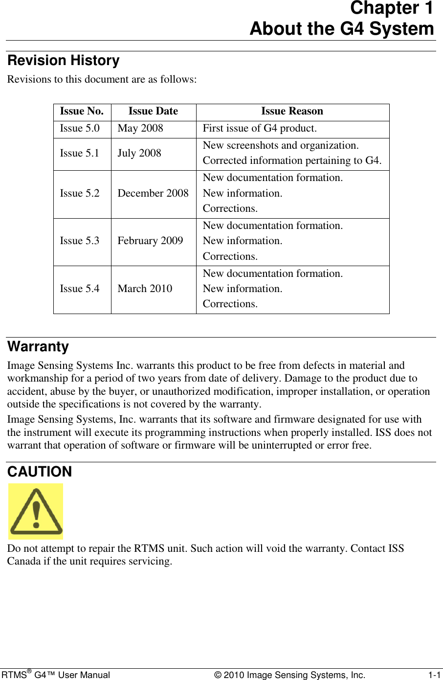
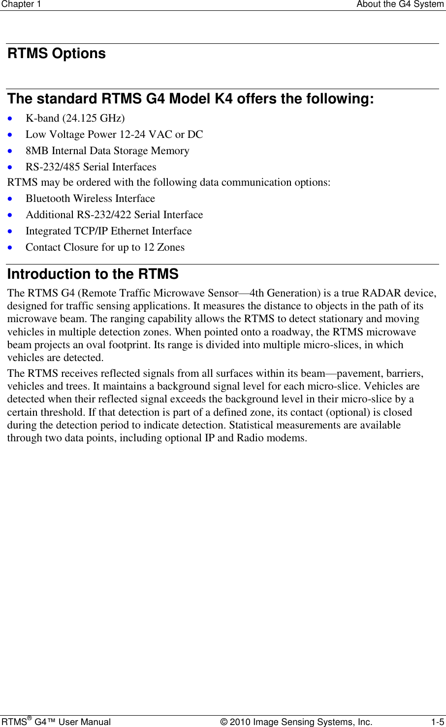
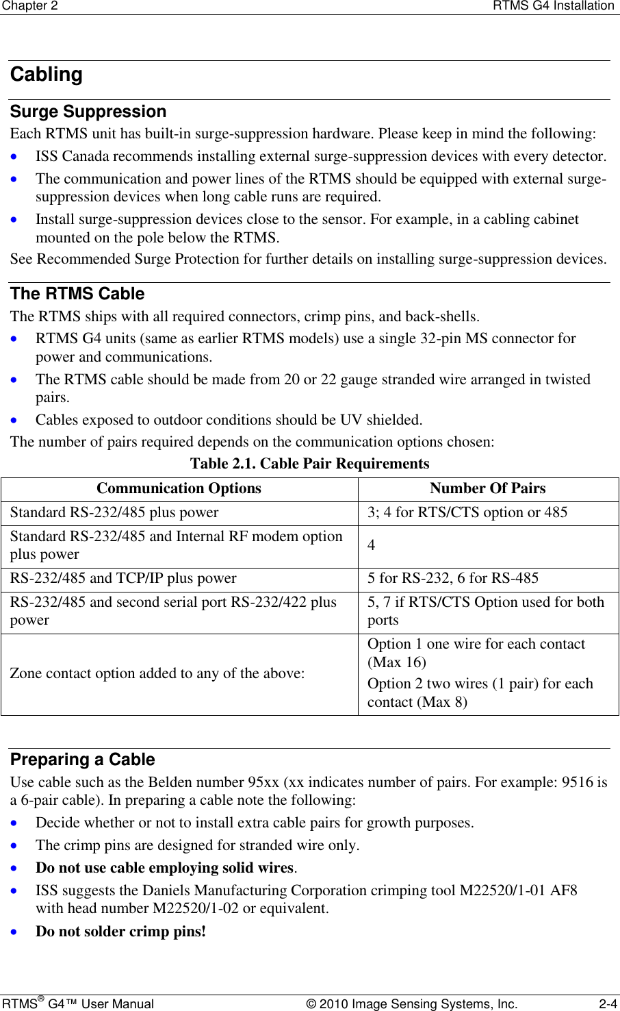
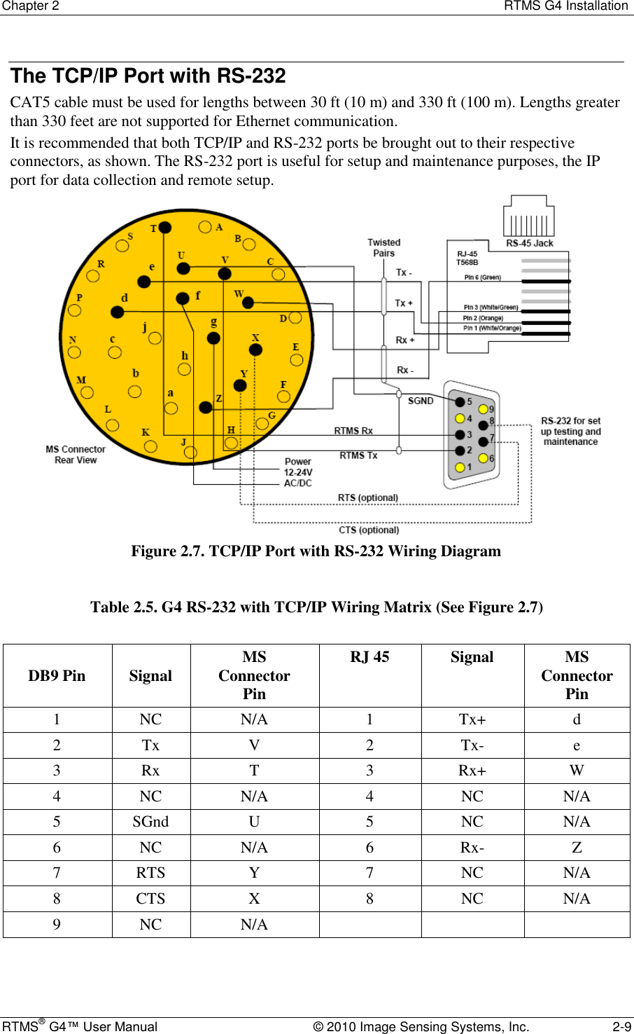
![Chapter 2 RTMS G4 Installation RTMS® G4™ User Manual © 2010 Image Sensing Systems, Inc. 2-17 RTMS Technical Specifications Microwave Signal and Coverage Area Model K4 Center Frequency 24.125 GHz Bandwidth 50 MHz Power Output 100 mW Beam Width—Vertical (Elevation) 50° Beam Width—Horizontal (Azimuth) 12° Side Lobes >-20 dB Range 6-250 feet [2-75 Meters] Number Of Detection Zones And Lanes 12 Accuracy of Measurement & Error Rates Measurement % Error * Per Lane Volume—Side-Fired 5% Volume Range 0-65535 Per Lane Occupancy—Side-Fired 5% Occupancy Range & Resolution 0-100%, 0.1% Per Lane Classification By Length (6 classes) 10% Class Lengths Limits range and resolution 83.6 ft [25.5 m 0.1 m] Average Per Vehicle Speed—Side-Fired 10% Speed range and resolution 100 MPH, 1 MPH [0-160 km/h, 1 km/h] Resolution of time events 1.25mS Voltage readout resolution 0.1v *Accuracy Performance Conditions Error performance parameters outlined above are achieved under normal, high-flow traffic conditions and are subject to proper installation and setup. Lower accuracy is expected under the following conditions: Low speed, high congestion conditions: The RTMS tends to be less accurate under very low speed conditions (below 1 mph [1.6 km/h]). Improper selection of installation site: insufficient set-back, height beyond the recommendation, obstruction by barriers or high fences before monitored lanes. Improper fine tune setting for the road geometry (lane width, barriers, etc.) will result in ―splashing‖ and, therefore, over-counting. In Forward-Looking Hwy configuration the following conditions may result in errors: High variance between the volumes in the speed trap zone. Improper aiming, mounting height (too high) or incorrect offset parameters Obstructions within the trap range.](https://usermanual.wiki/Image-Sensing-Systems/RTMS-K4S/User-Guide-1591677-Page-29.png)
![Chapter 2 RTMS G4 Installation RTMS® G4™ User Manual © 2010 Image Sensing Systems, Inc. 2-18 Mechanical Measurement Dimensions Enclosure Dimensions 8×8×6 inches [21×21×16 cm ] Weight (Without Optional Equipment) 3.5 pounds [1.5kg] Enclosure Material polycarbonate Weatherproofing NEMA-4X and IP-65 Mounting Zinc plated steel universal ball-joint bracket capable of support a load of up to 20 lbs [8.33 kg]. (Vertical or horizontal). Lynch-pin locking allows quick sensor replacement without disturbing the aiming. Allowable pole flexing Less than 5 degrees Power Requirements & Consumption Component Details RTMS standard power requirement 12-24 VAC or DC Polarity protection not polarity sensitive Over-voltage shutdown limit 34 VDC or 24 VAC Recommended fusing (external) 2 A slow blow minimum Power consumption (Without optional equipment) 3 Watts Automatic recovery from power failure Within 20 seconds Commercial AC power option 115±20 VAC @ 50-60 Hz Interfaces Isolated Serial ports programmable to RS-232/485 including hardware handshake. (Second serial port is only available with additional hardware.) Speed is adjustable between 2400 and 115200 bits-per-second. RS-485 range: up to 4000 feet [1200 m]. Optional Bluetooth wireless connection Optional Second Serial port programmable to RS-232/422 including hardware handshake Optional integral 10/100 Base-T Ethernet supporting TCP, UDP, IP, ARP, ICMP Optional IP Camera with multiple modes of operation (See separate specification.) Optional Contact pairs: 8 isolated contacts or 16 common ground contacts rated at Maximum current 100 mA; Maximum voltage 350 V; Maximum dissipated power 300 mW. Internal Data memory capacity: 8 Mb (90 days with all reporting options on and a 5-minute message period, 6 months for typical configuration.) Upgrade Capability](https://usermanual.wiki/Image-Sensing-Systems/RTMS-K4S/User-Guide-1591677-Page-30.png)
![Chapter 2 RTMS G4 Installation RTMS® G4™ User Manual © 2010 Image Sensing Systems, Inc. 2-19 User upgrades of both hardware and firmware available. RTMS supports remote firmware upgrade. Surge Immunity The RTMS withstands ±1kV surge (rise time = 1.2 µsec, hold = 50µsec) applied in differential mode to all lines, power and output, as defined by IEC 1000-4-5 and EN 61000-4-5 standards. Environmental Conditions Operating Limits Shipping & Storage Temperature Range -35 to 165°F [-37 to +74°C ] -40° to 171°F [-40° to 80°C] Humidity Up to 95% Relative Humidity Up to 95% Relative Humidity Vibration 2 g up to 200 Hz Shock 5 g 10 ms sine wave Wind Winds up to 100 mph [160 km/h] will not degrade performance Precipitation Up to 100 mm/h Printed circuit boards are conformally coated for protection against humidity and corrosion. Except as may be other stated herein for a particular item, no item, component, or subassembly shall emit a noise level exceeding the peak level of 55 dBa when measured at a distance of one meter away from its surface. Electromagnetic Interference Certified under US FCC Rule part 15 Class A; Canadian CSA C108.8 M1983 Class A; CE. Reliability The RTMS is designed for Mean Time Between Failures (MTBF) in its operating environment of 90000 hours [10 years].](https://usermanual.wiki/Image-Sensing-Systems/RTMS-K4S/User-Guide-1591677-Page-31.png)