Intuitive Surgical CHB01 RFID TRANSCEIVER 3D-HD CAMERA HEAD User Manual da Vinci Si
Intuitive Surgical, Inc. RFID TRANSCEIVER 3D-HD CAMERA HEAD da Vinci Si
Contents
- 1. User Manual Part 1
- 2. User Manual Part 2
- 3. User Manual Part 3
- 4. User Manual Part 4
User Manual Part 3
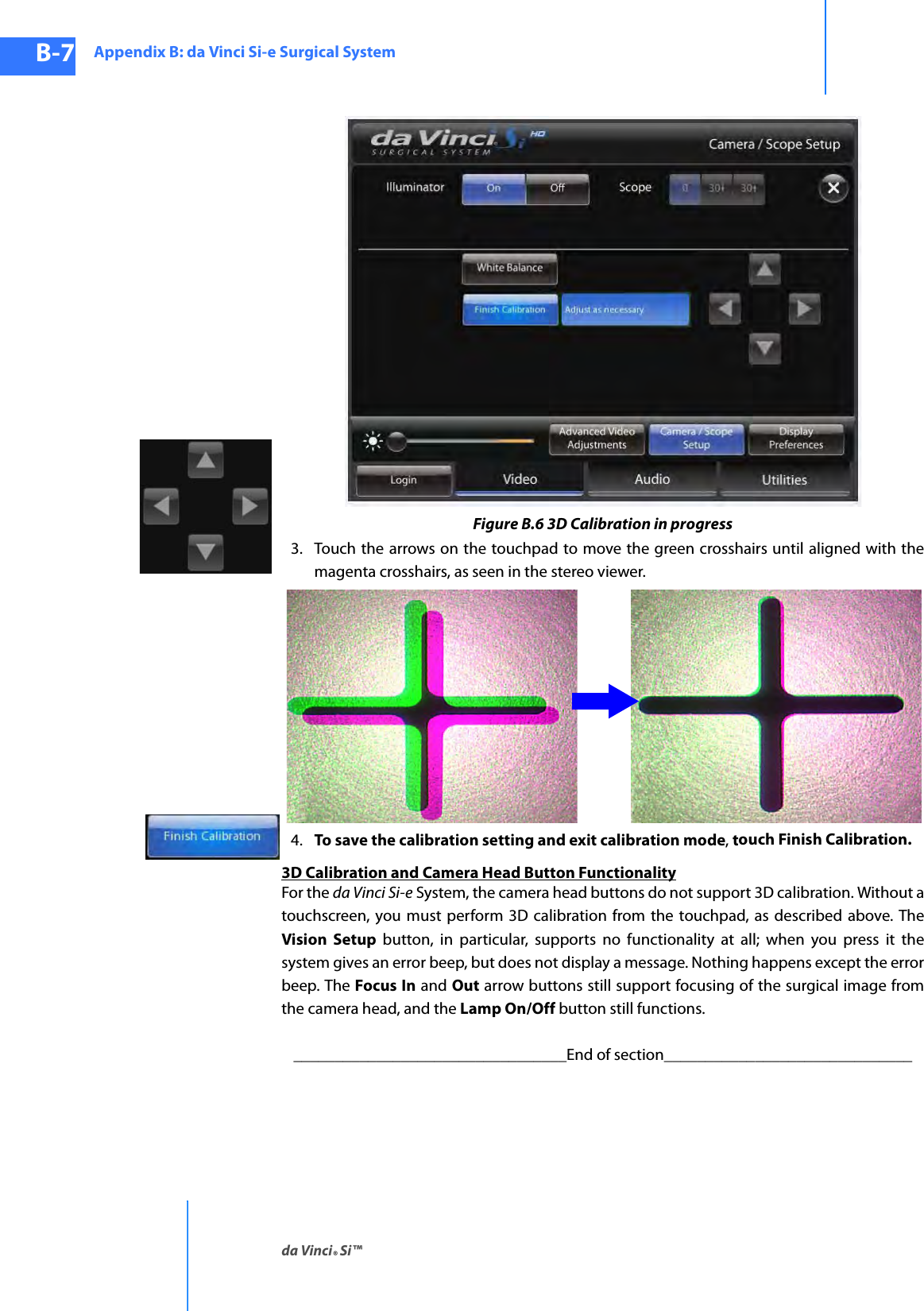
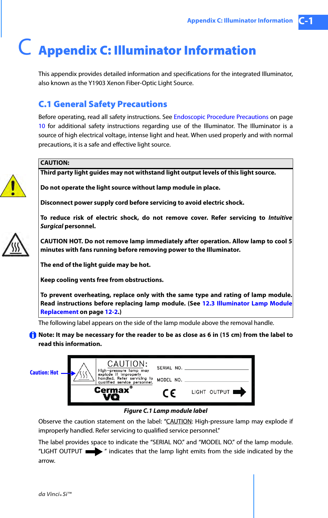
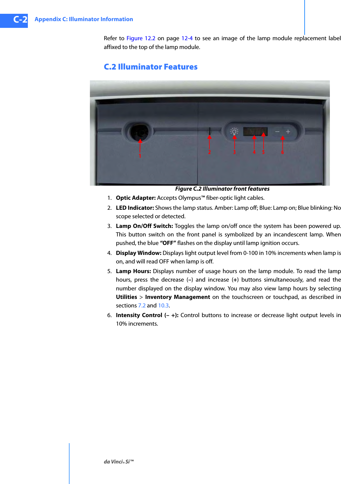
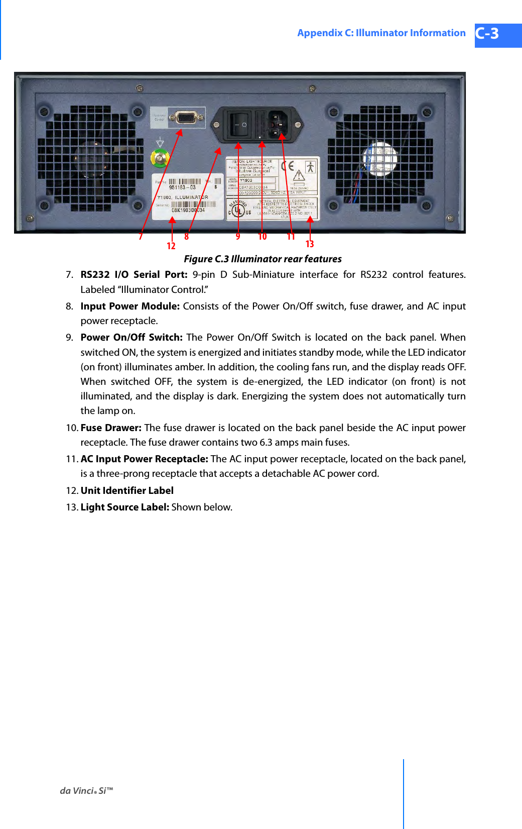
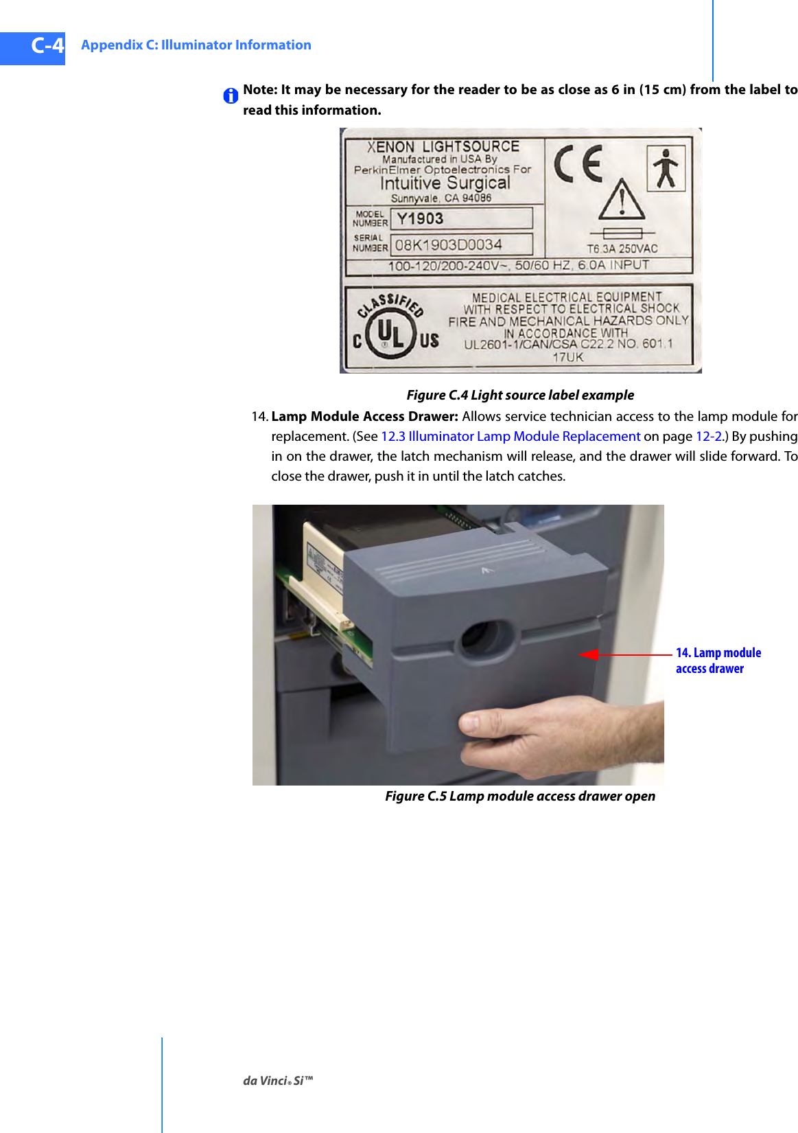
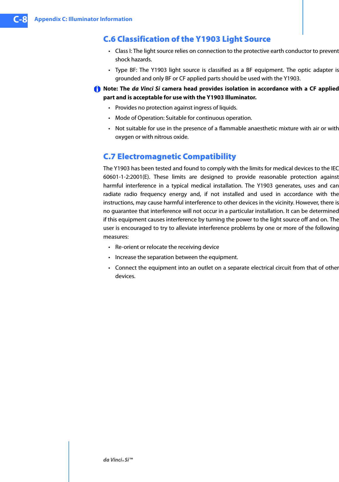
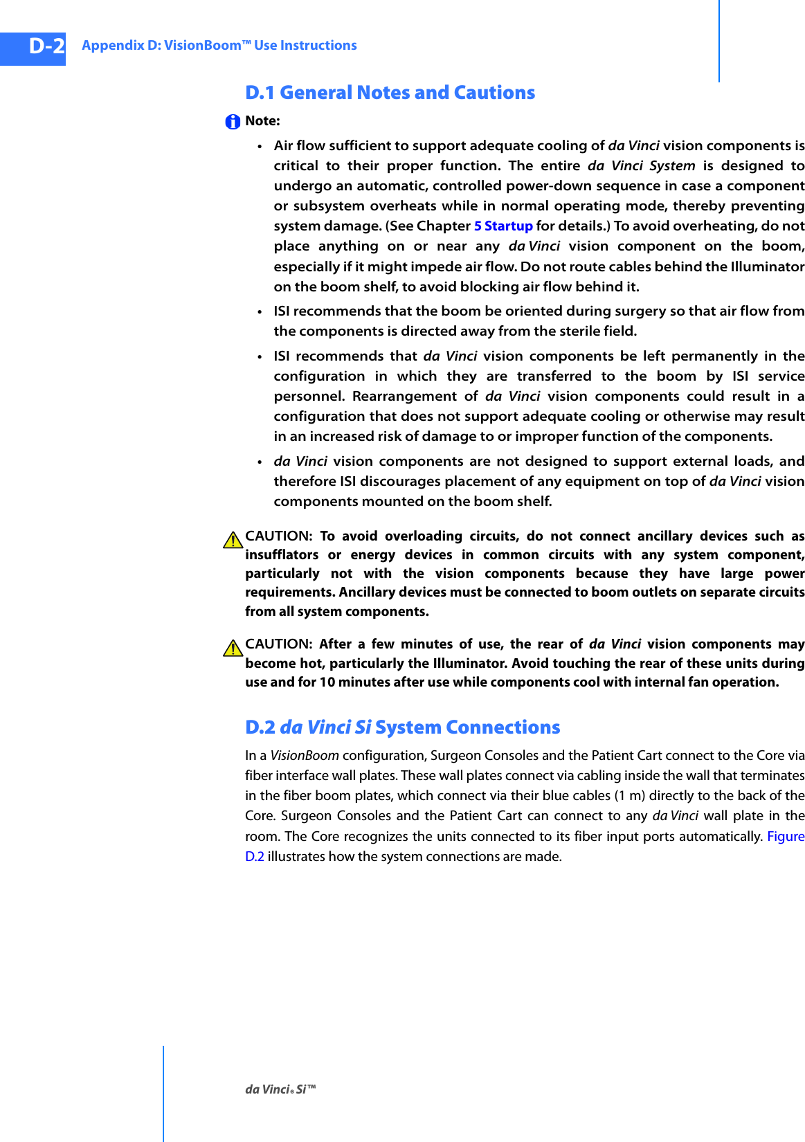
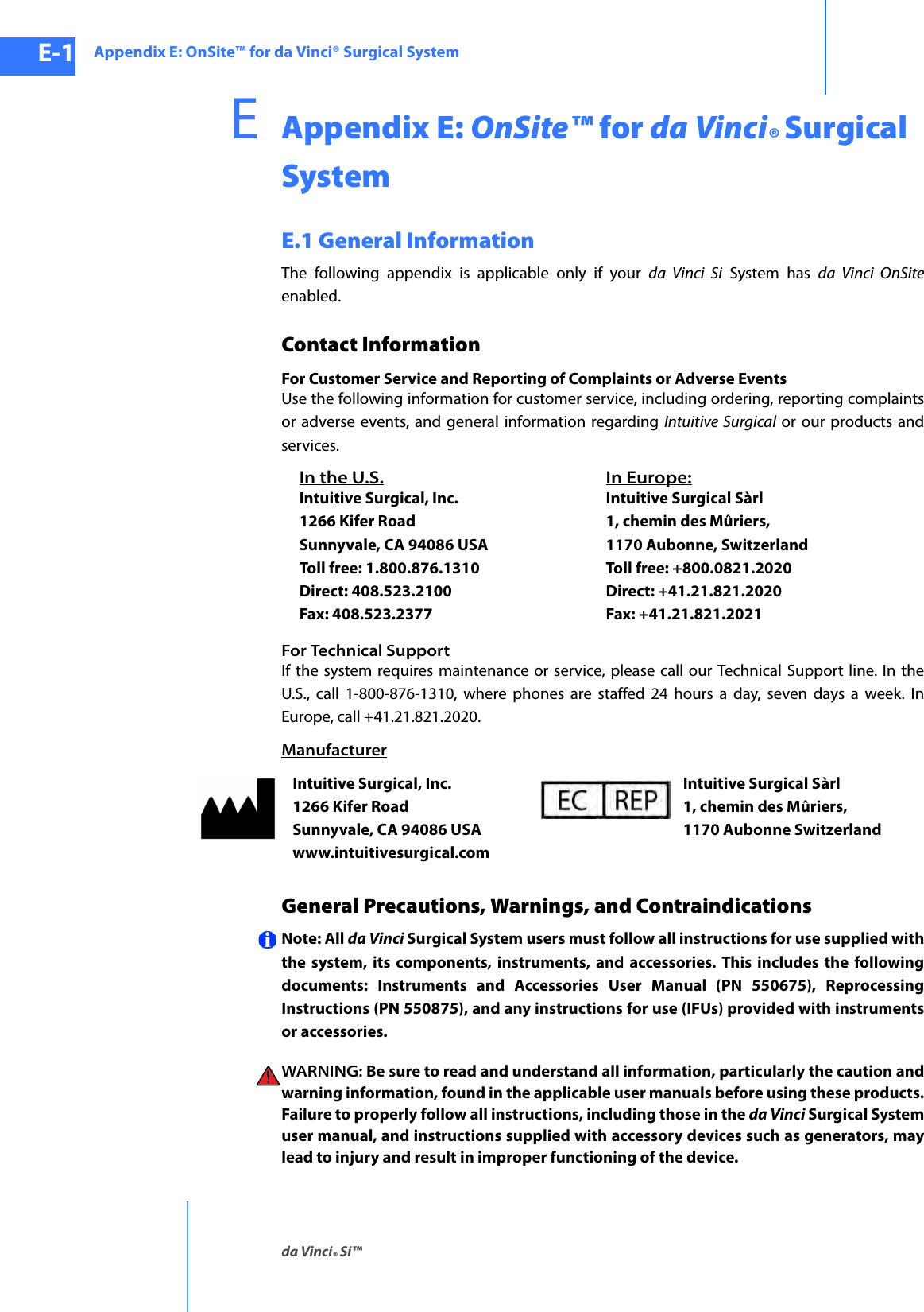
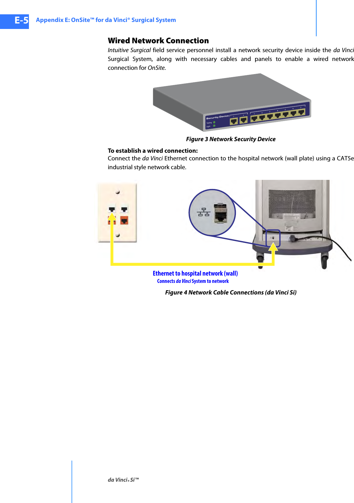
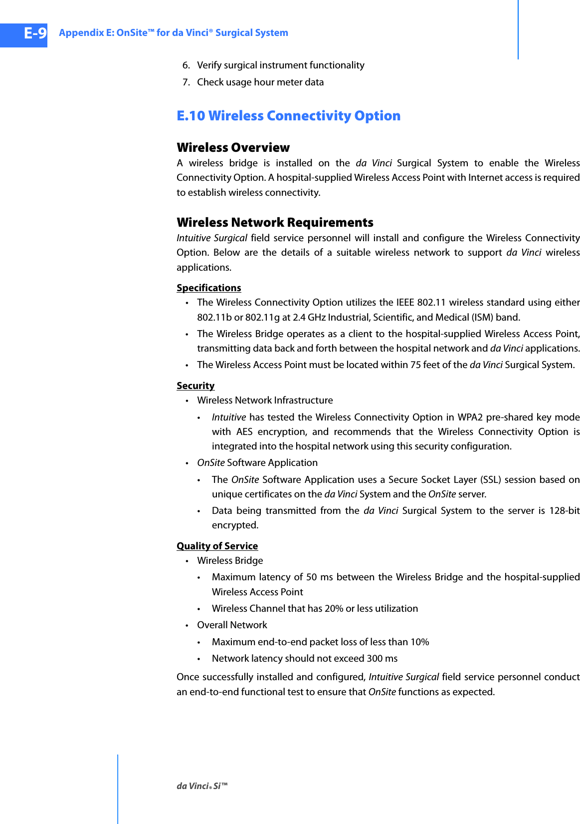
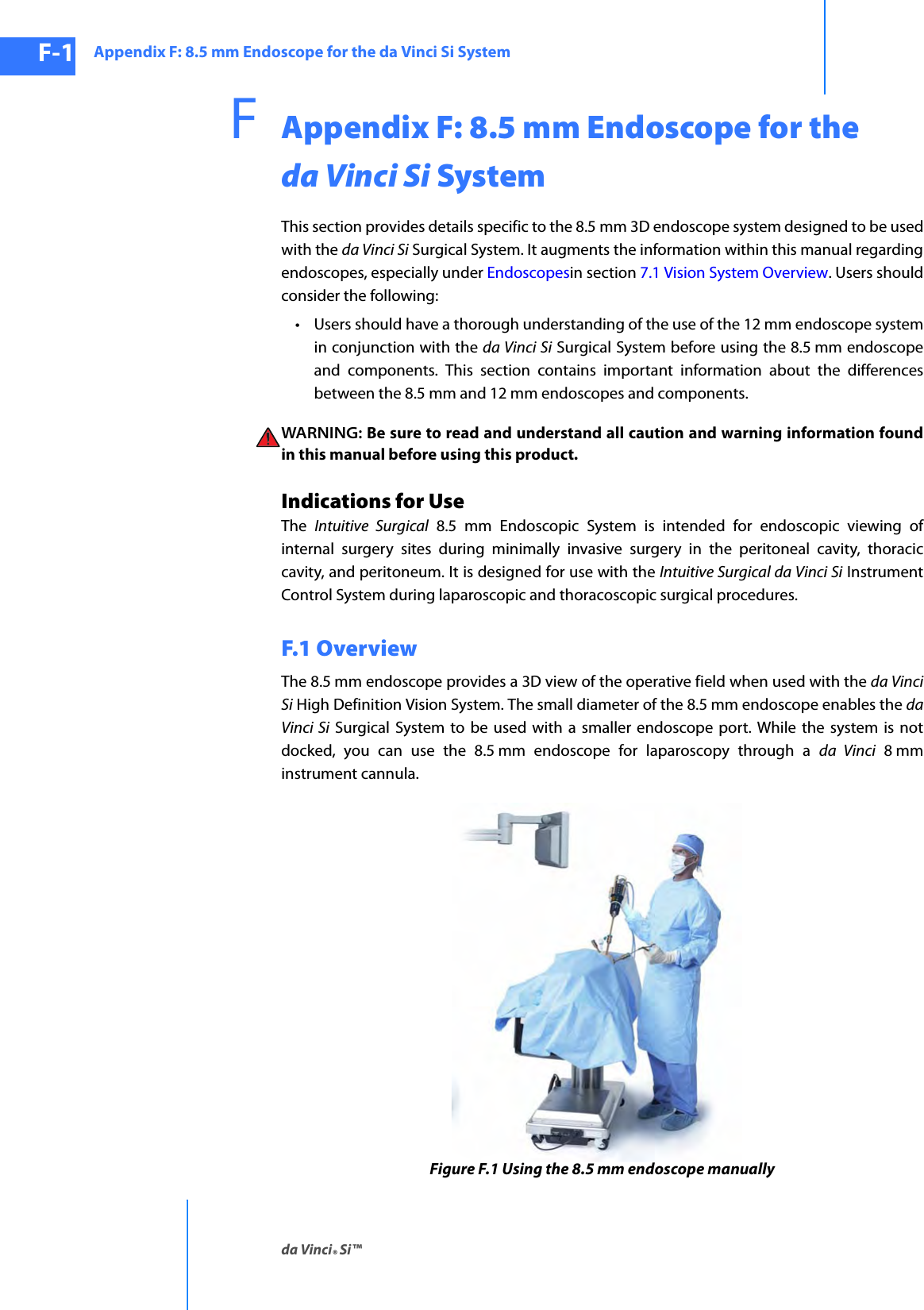
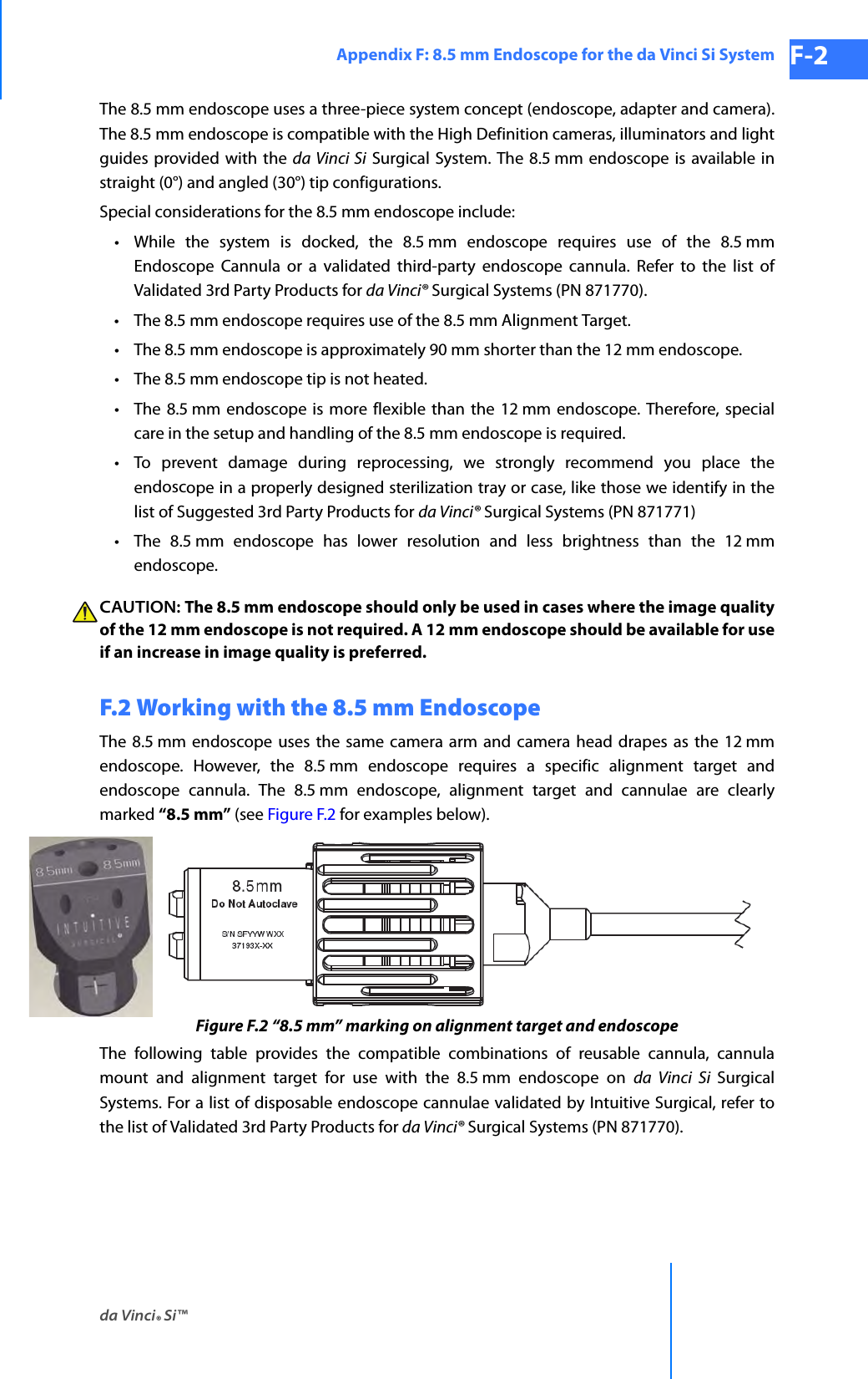
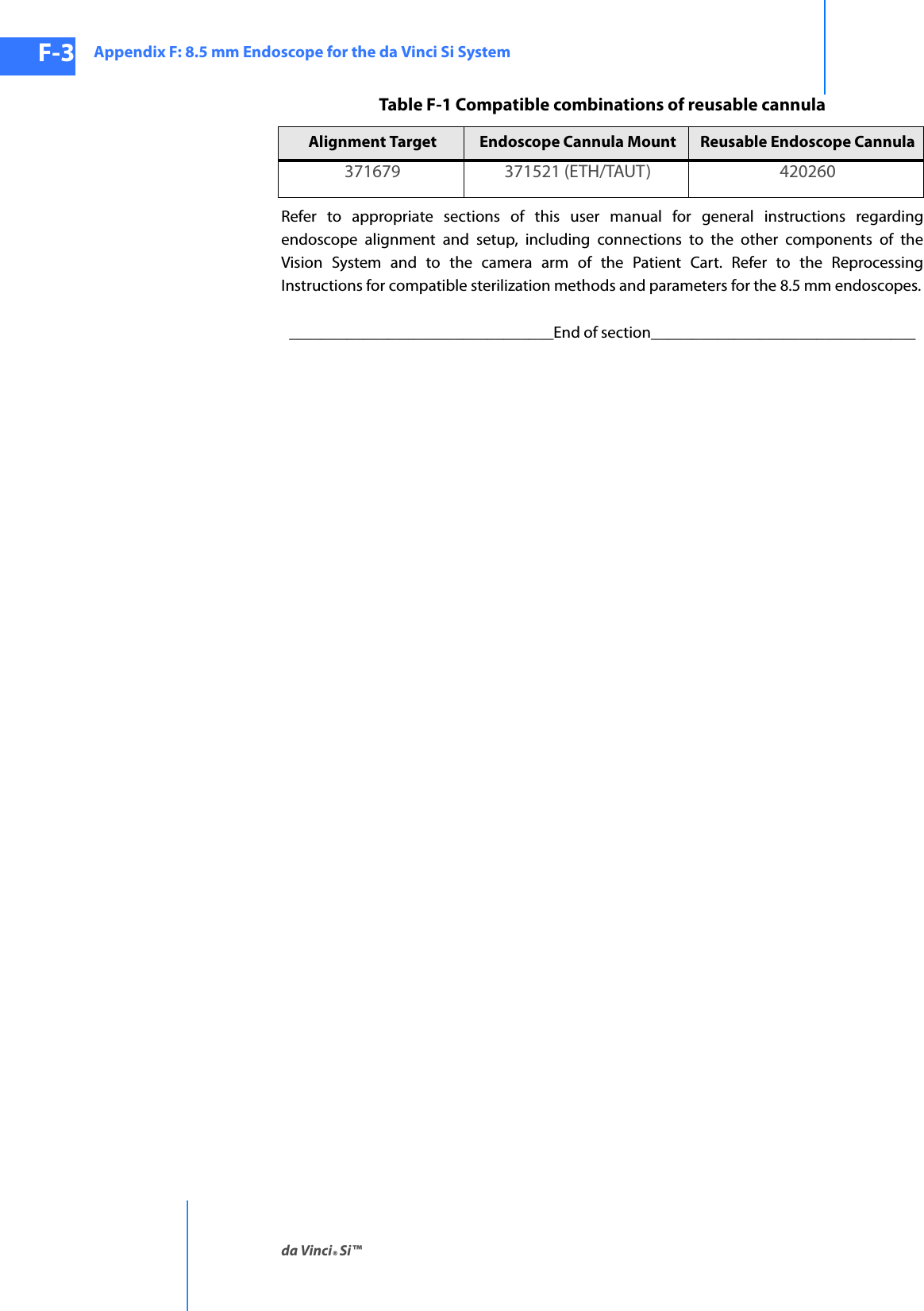
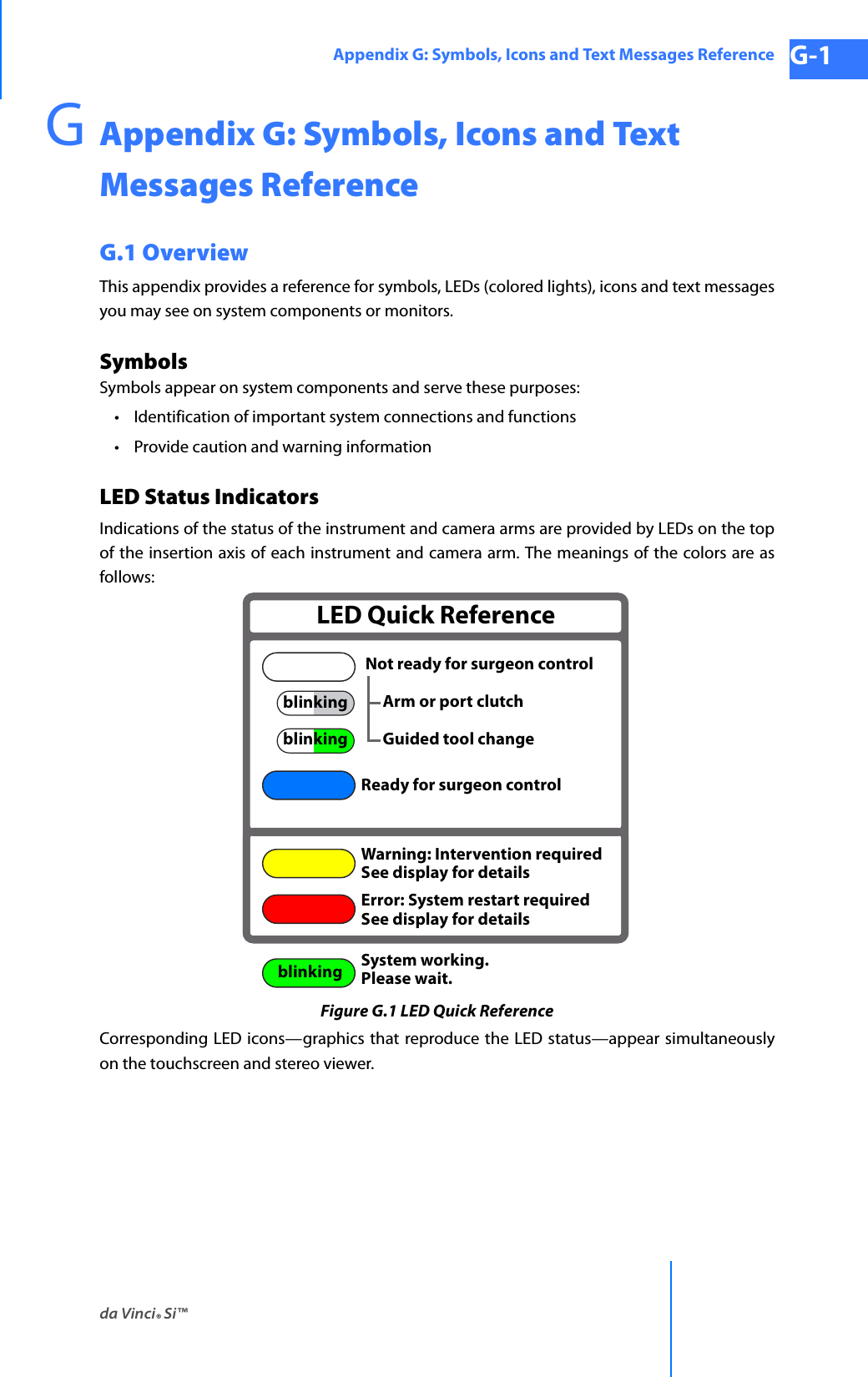
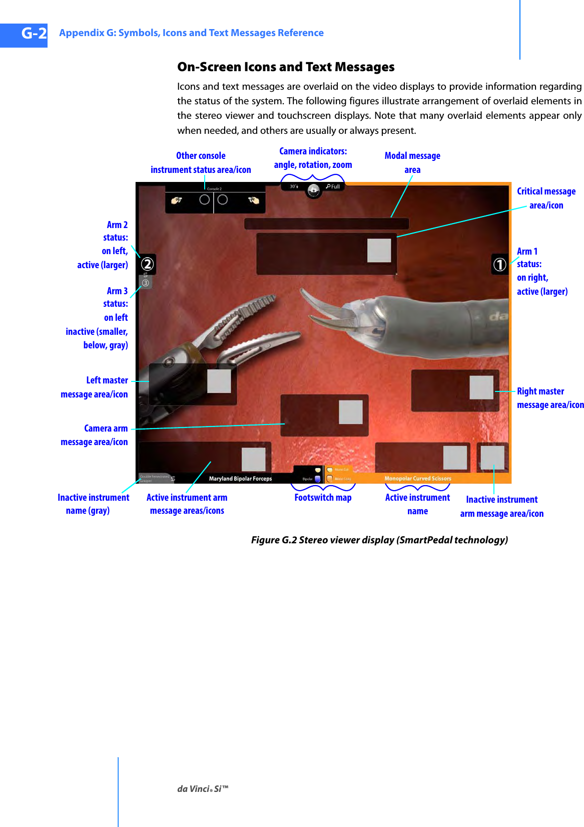
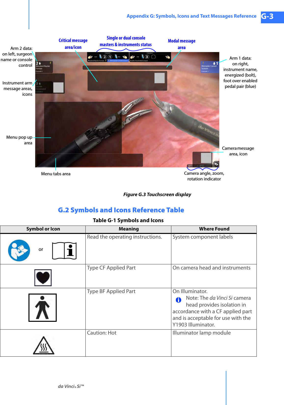

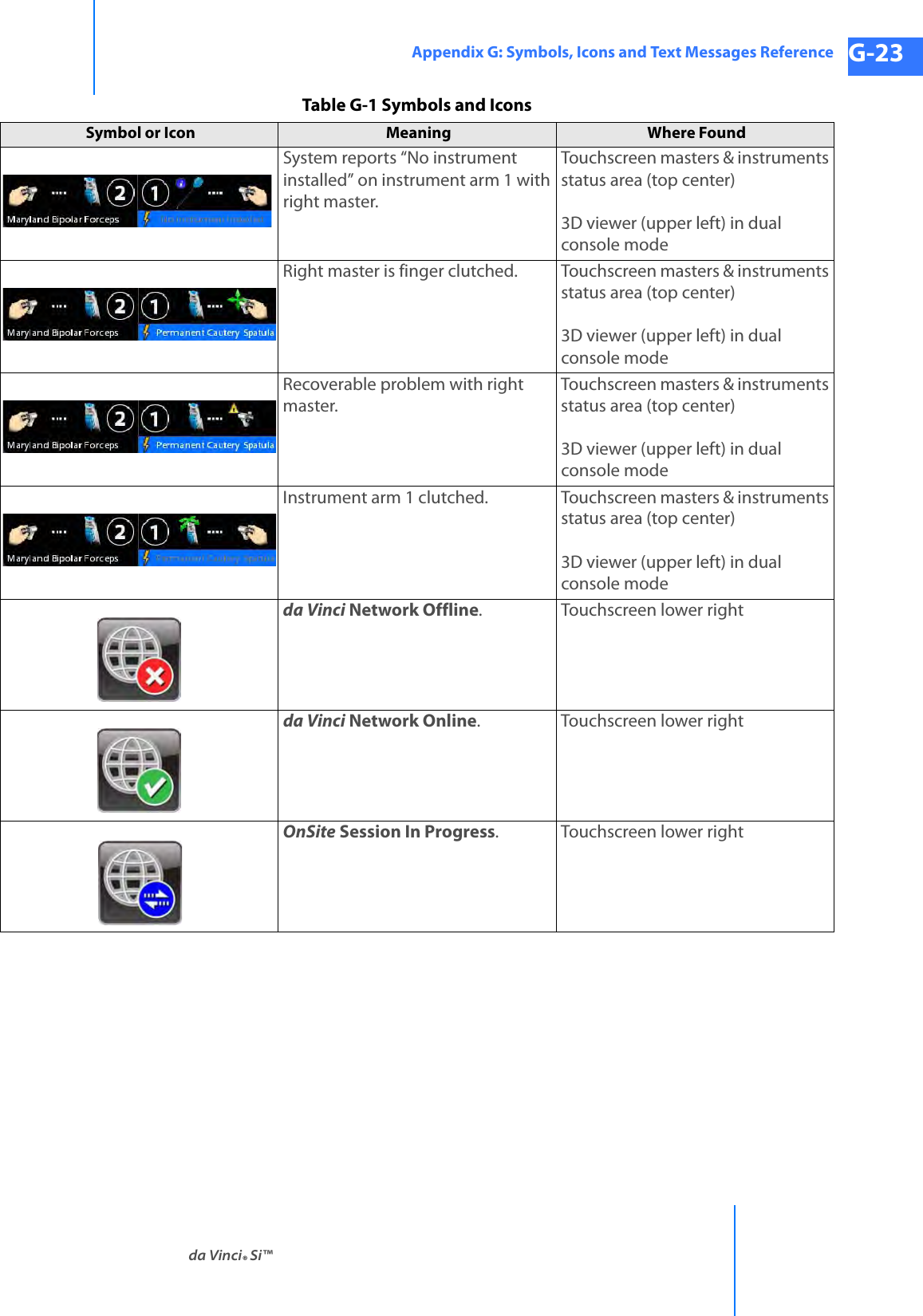
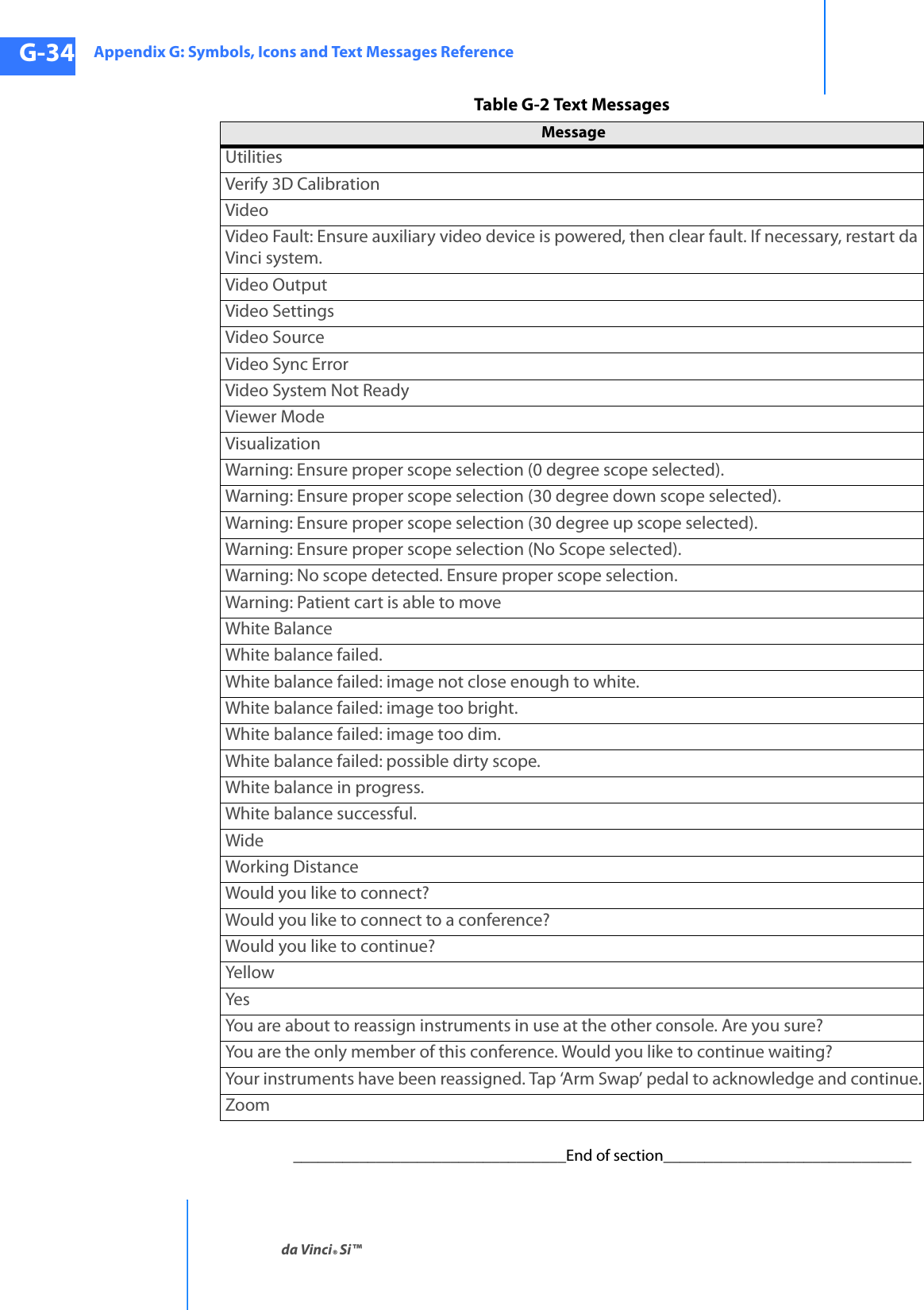
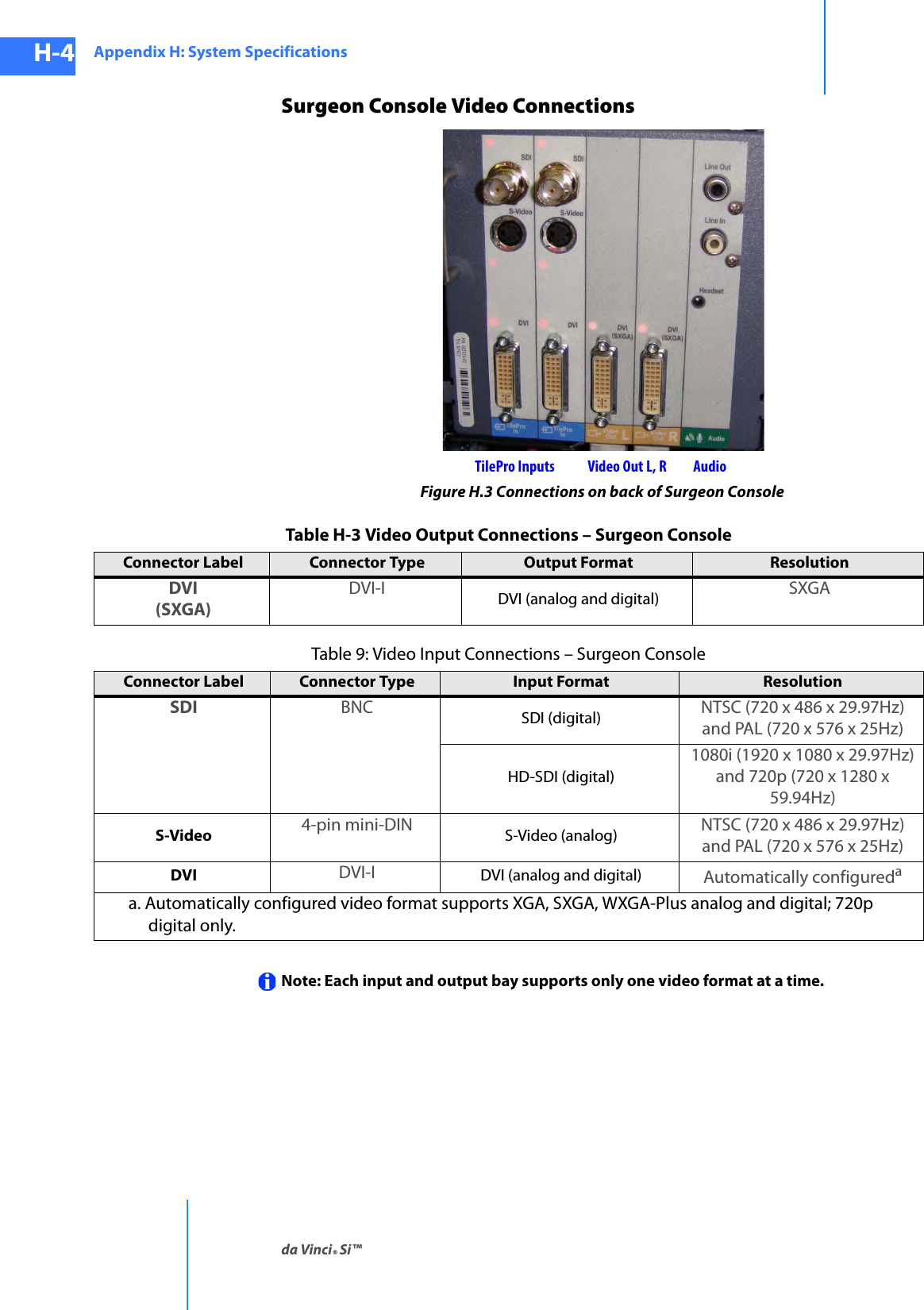
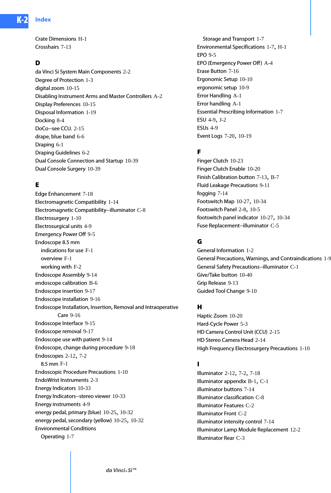
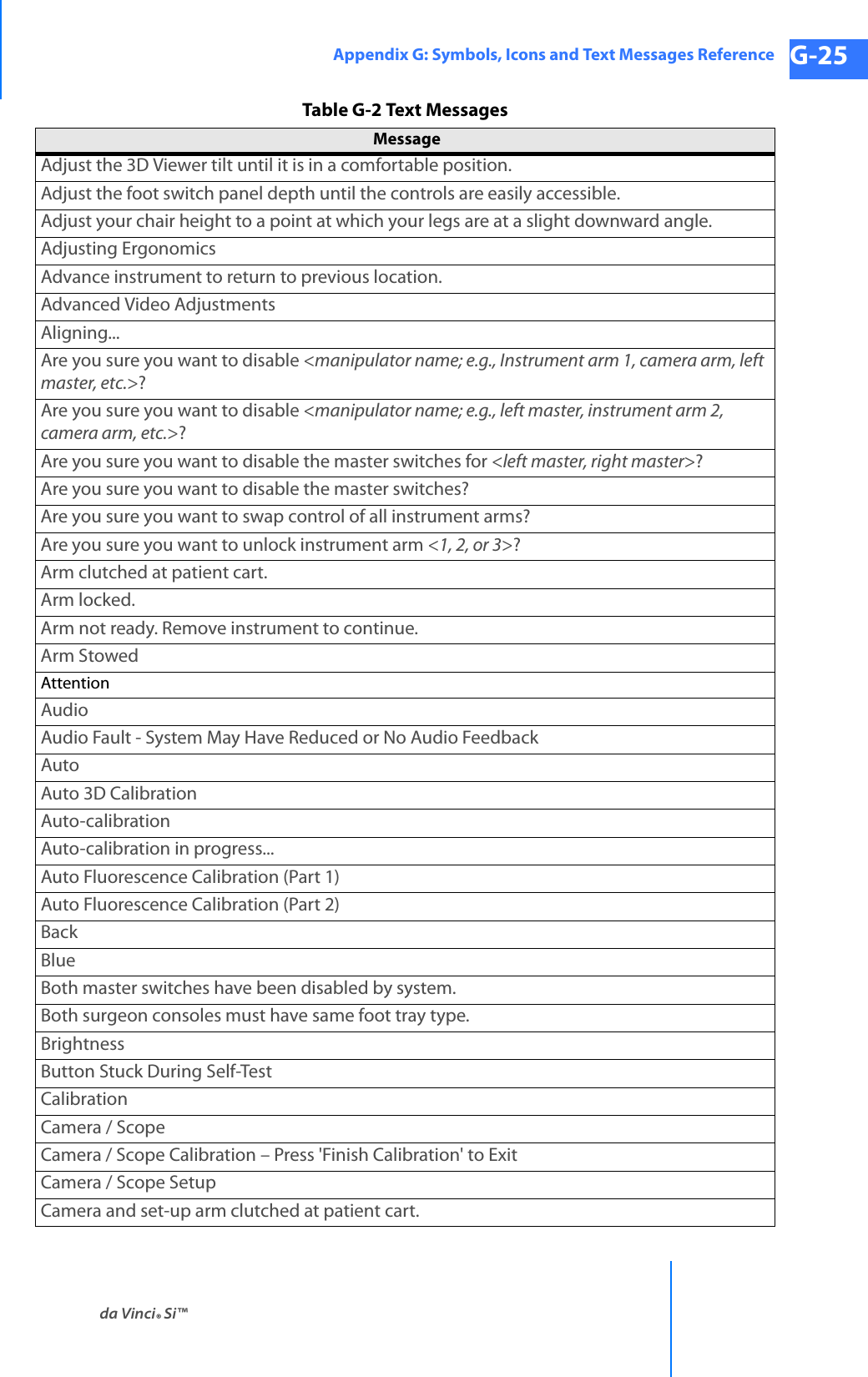
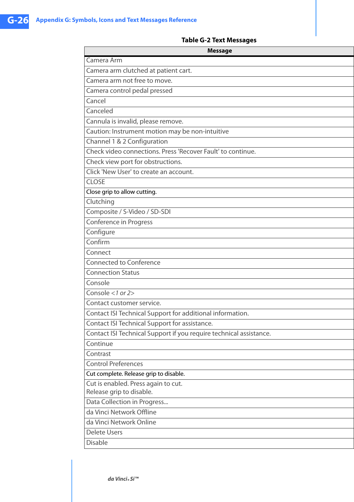
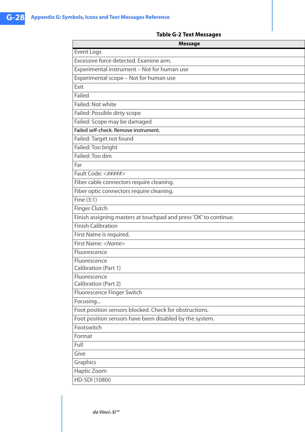
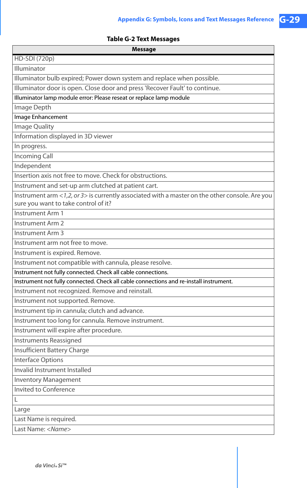
![Appendix G: Symbols, Icons and Text Messages Referenceda Vinci® Si™G-24DRAFT/PRE-RELEASE/CONFIDENTIAL10/9/14G.3 Text Messages Reference TableTable G-2 contains a list of text messages that can appear on screen, sorted alphabetically. The text messages can appear in one or several contexts and locations and are written so as to be understood in each context on screen, and therefore not explained further. Variables are shown in italics inside angled brackets, like this: <variable>. This table is provided as a reference and to support translation into languages not supported in the system software.Table G-2 Text MessagesMessage # A B C P1 P2 P3 P4 T<button name> Button Stuck During Self-Test.<ESU name> is currently connected to your system. Would you like to continue or disconnect?<Left master, Right master> switches have been disabled by system. [This is repeated in table for optional “Left” and “Right” starting letters.]<Monopolar, Bipolar, etc.> energy disabled; only one <Monopolar, Bipolar, etc.> device is allowed<Monopolar, Bipolar, etc.> and <Monopolar, Bipolar, etc.> energy disabled during simultaneous control<Surgeon Console, Patient Side> Overlay [This is repeated in table for optional “Surgeon” and “Patient” starting letters.]<User name> has connected.<User name> has disconnected.<User name> has invited you to join a conference. Would you like to accept?02D2x303-arm Patient Cart not supported.Power down, connect 4-arm Patient Cart, and restart.3D3D Calibration3D Viewer Blocked4-arm Patient Cart not supported.Power down, connect 3-arm Patient Cart, and restart.4xA fault has occurred.A remote userAcceptAccount InfoAccount ManagementAdjust as necessaryAdjust the 3D viewer height until it is in a comfortable position.](https://usermanual.wiki/Intuitive-Surgical/CHB01.User-Manual-Part-3/User-Guide-2607926-Page-76.png)
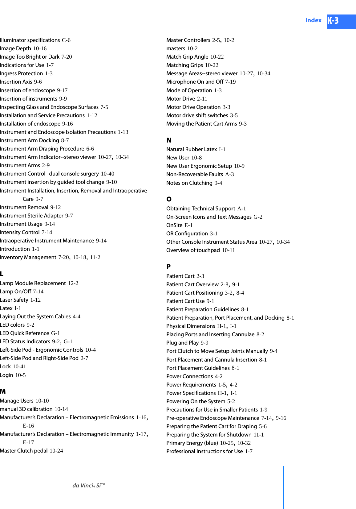
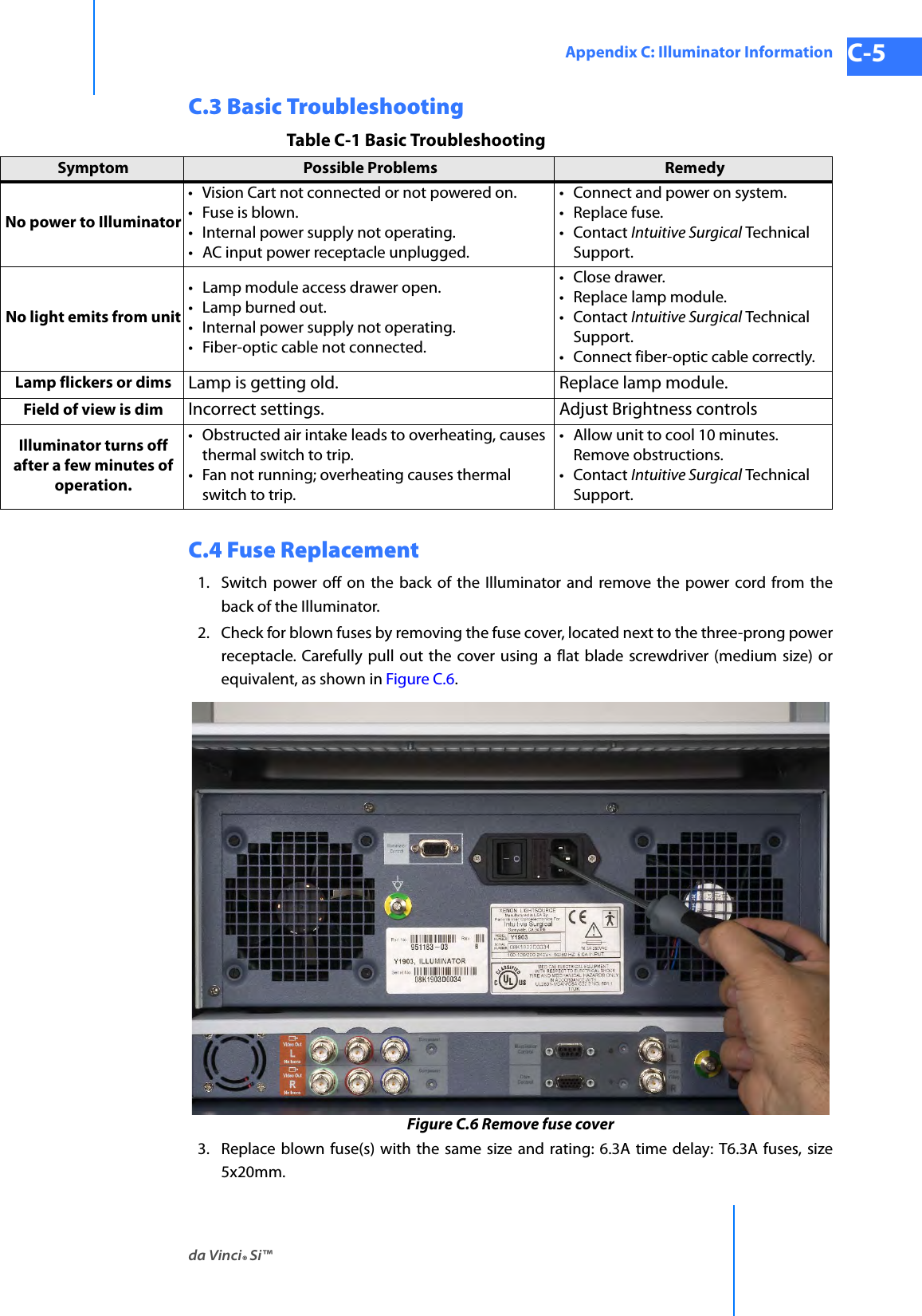
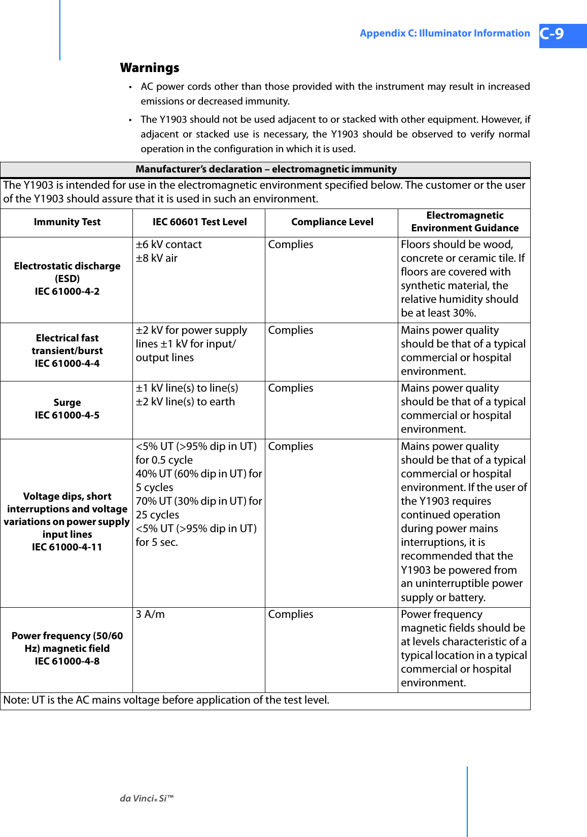
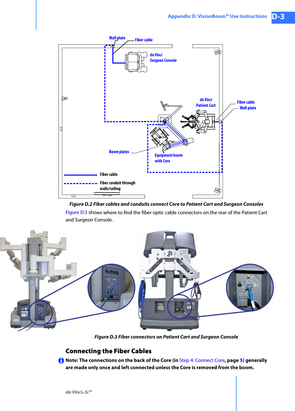
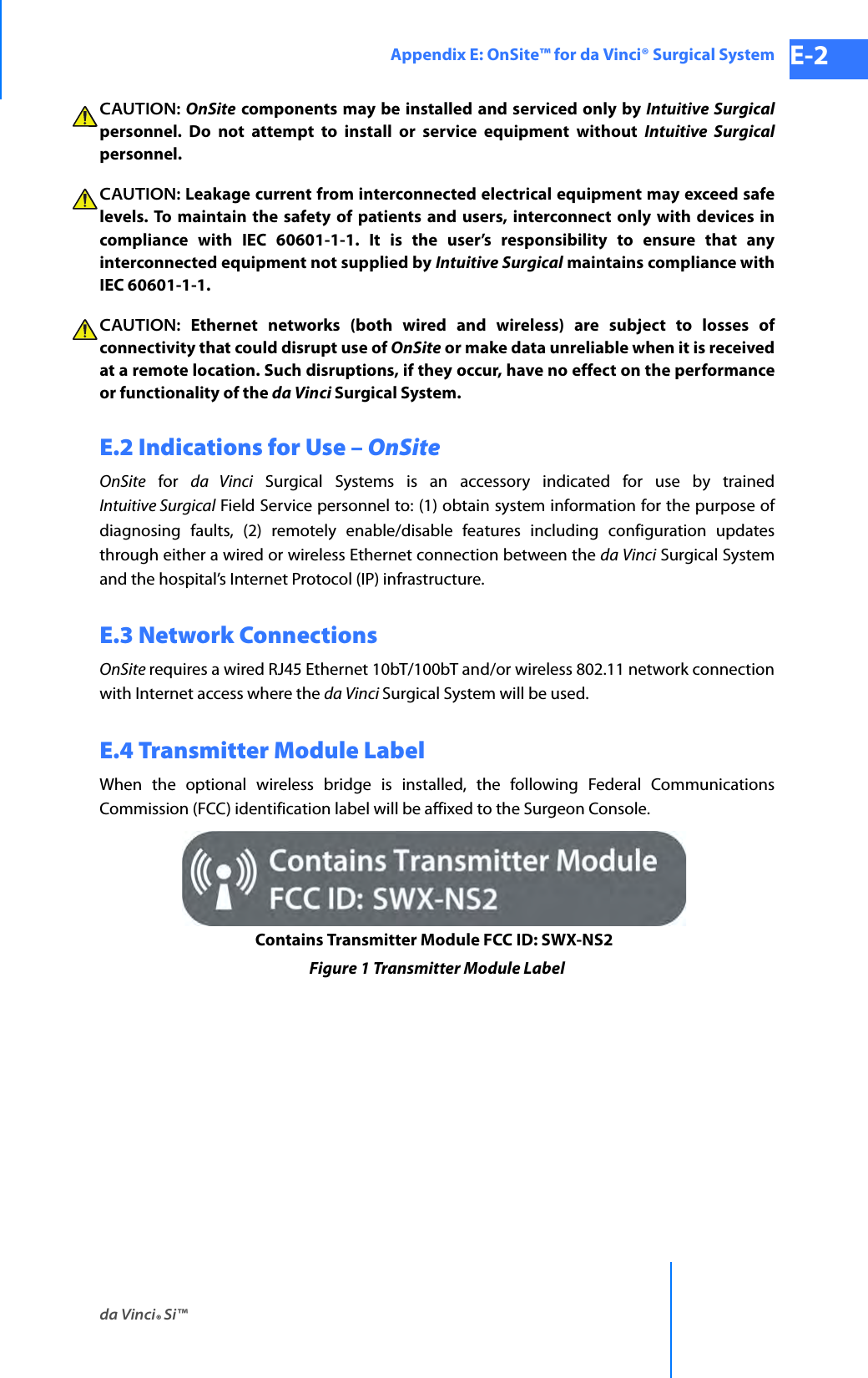
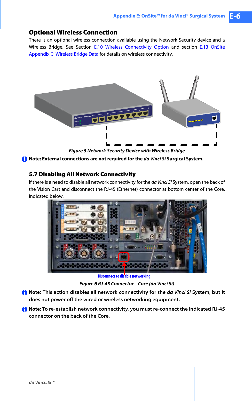
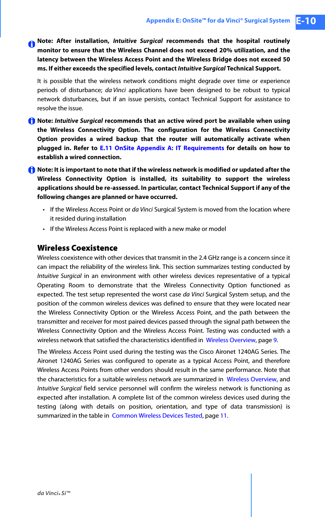
![da Vinci® Si™Appendix G: Symbols, Icons and Text Messages Reference G-27DRAFT/PRE-RELEASE/CONFIDENTIAL 10/9/14Disable <name of manipulator; e.g., instrument arm 1, camera arm, right master, etc.> or restart system to continue.Disable ArmDisable NodeDisable SwitchesDisconnectDisconnect one console and reset system to continue.Disconnect one surgeon console and press 'Recover Fault' to continue.Disconnect or unpower <ESU name> or <ESU name> to resolve.[Note: This message appears when two ESUs have conflicting features. Both are listed by name, so one example would be: “Disconnect or unpower Conmed or ValleyLab to resolve.”]Display EyeDisplay Name is required.Display name must be unique.Display Name: <Name>Display PreferencesDoes this calibration look correct?DoneDon't show this message againDownloading data, please wait: <#>Dr. <Name>Dual Console Mode Not SupportedDual console not supported.Power down, disconnect Surgeon Console, and restart.DVI-D (720p)DVI-IDVI-I (1024x768)DVI-I (1280x1024)DVI-I (1440x900)Edge EnhancementEditEdit <user name> AccountEdit UserEmergency Stop ActivatedEnableEndoscopic ViewEnergy Device ConflictEnsure the network cable is properly connected.<ESU name> is currently connected to your system. Would you like to continue or disconnect?Table G-2 Text MessagesMessage](https://usermanual.wiki/Intuitive-Surgical/CHB01.User-Manual-Part-3/User-Guide-2607926-Page-79.png)
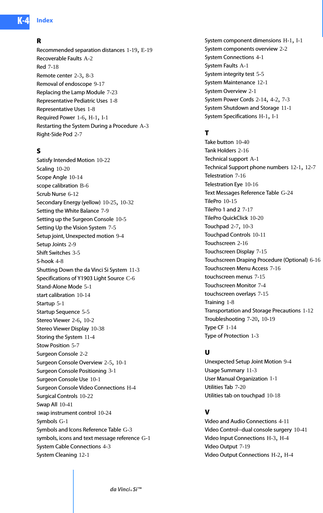
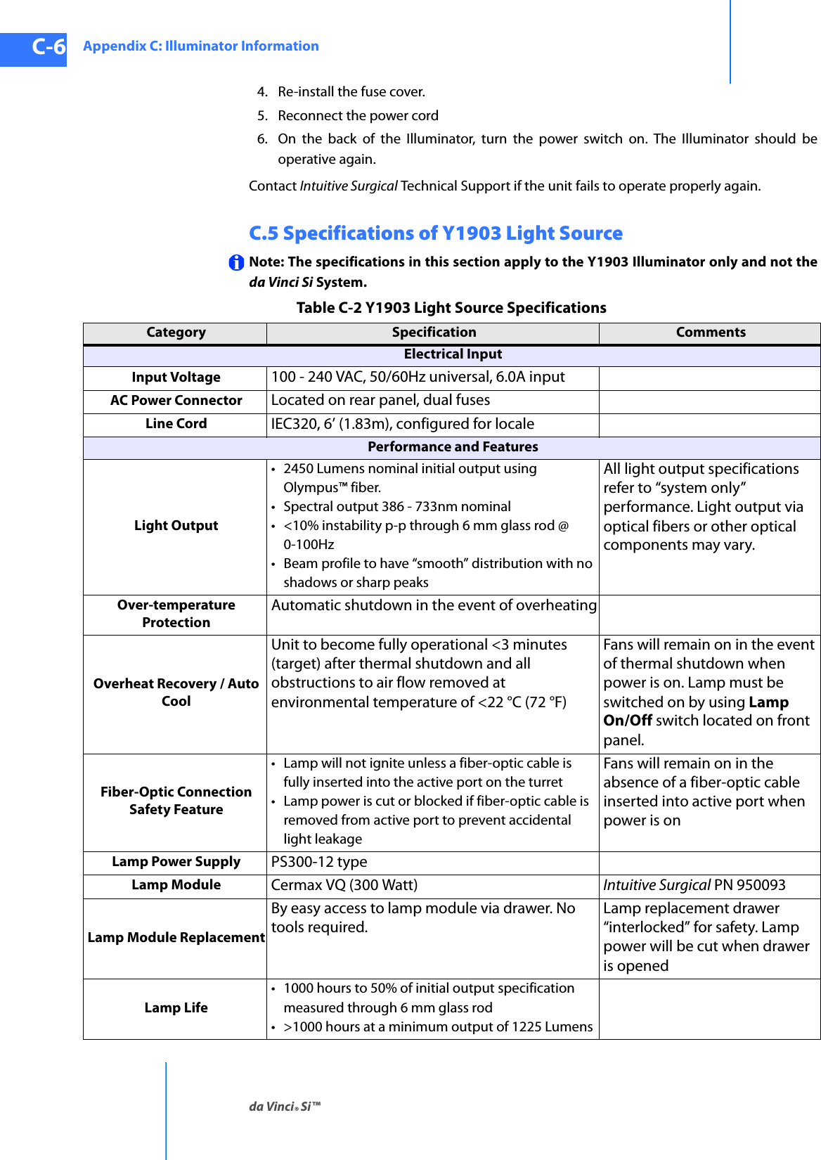
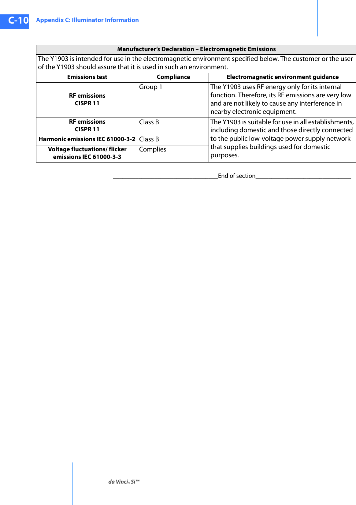
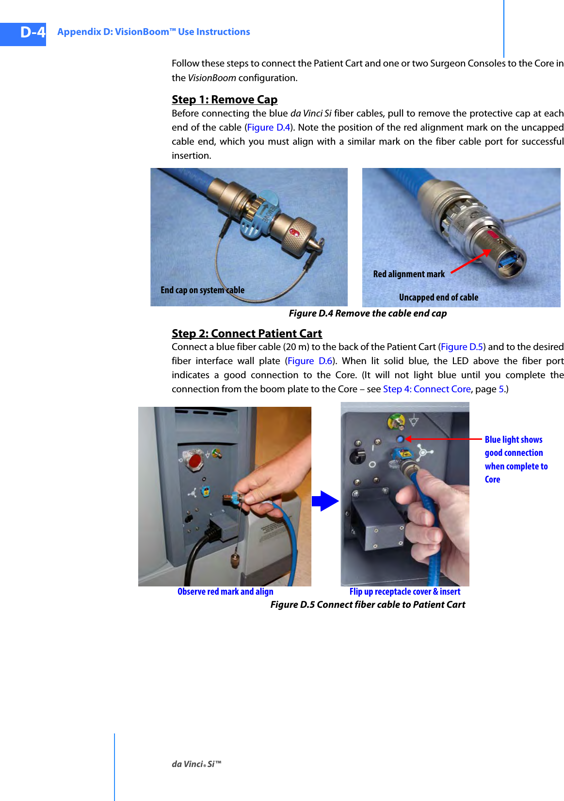
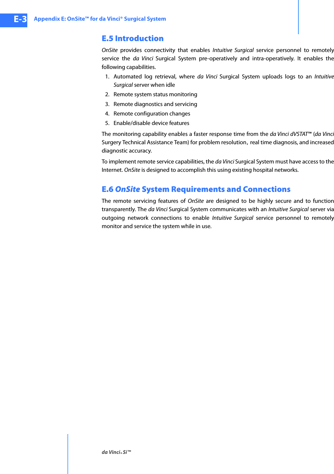
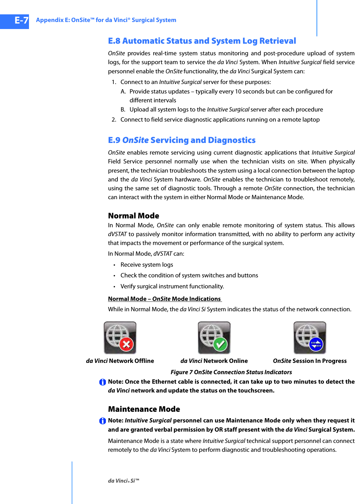
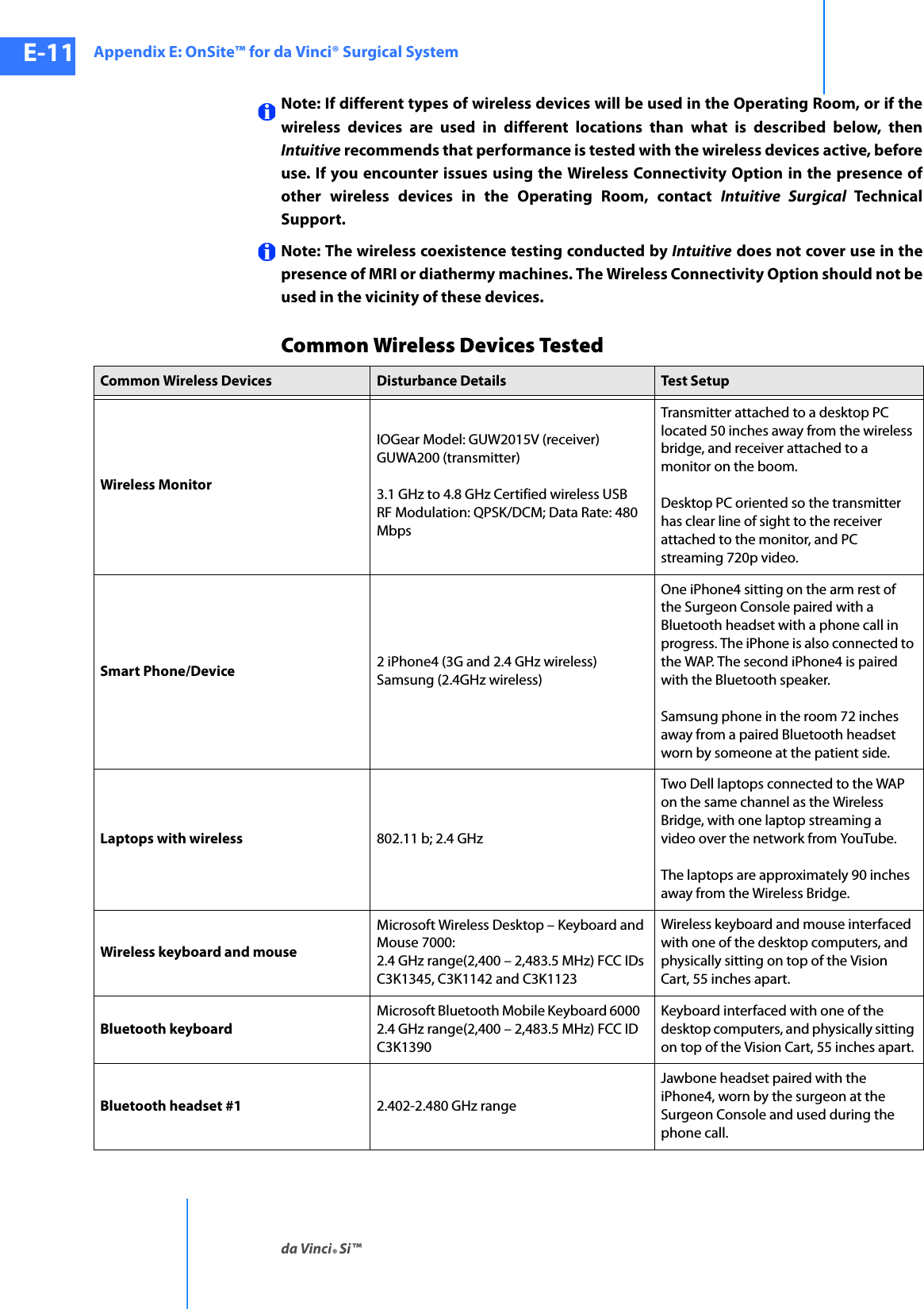
![Appendix G: Symbols, Icons and Text Messages Referenceda Vinci® Si™G-30DRAFT/PRE-RELEASE/CONFIDENTIAL10/9/14Left Master<Left master, Right master> switches have been disabled by system. [This is repeated in table for optional “Left” and “Right” starting letters.]Left video lost. Check video connections and power.LockLoginLogoutMaintenance Mode – Not for human useMaintenance Mode – Not for human use (Console 1)Maintenance Mode – Not for human use (Console 2)Manage UsersManualMaster AssociationsMaster Associations IncompleteMaster Controller Assignments IncompleteMaster not free to move.Master ScalingMaster Switch ErrorMaximum of two arms per side.Move master grip to match instrument.Networking hardware fault. OnSite and Connect functionality no longer available. Press 'Recover Fault' to continue.Network DetectedNetwork UnavailableNew UserNew User (Step <step number> of <total number of steps>)NextNext LogNoNo battery backup.No battery backup. Contact customer service.No cannula detected. Remove instrument and check cannula.No Instrument InstalledNo Scope DetectedNo user logged in.No video signal. Check video connections and power.Non-recoverable FaultNon-recoverable Fault <fault number> Restart system to continue.Non-recoverable Subsystem FaultTable G-2 Text MessagesMessage](https://usermanual.wiki/Intuitive-Surgical/CHB01.User-Manual-Part-3/User-Guide-2607926-Page-82.png)
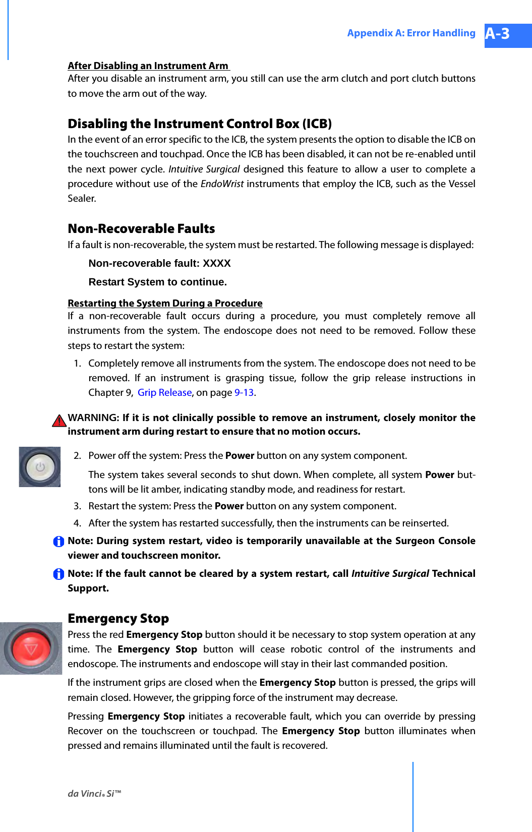
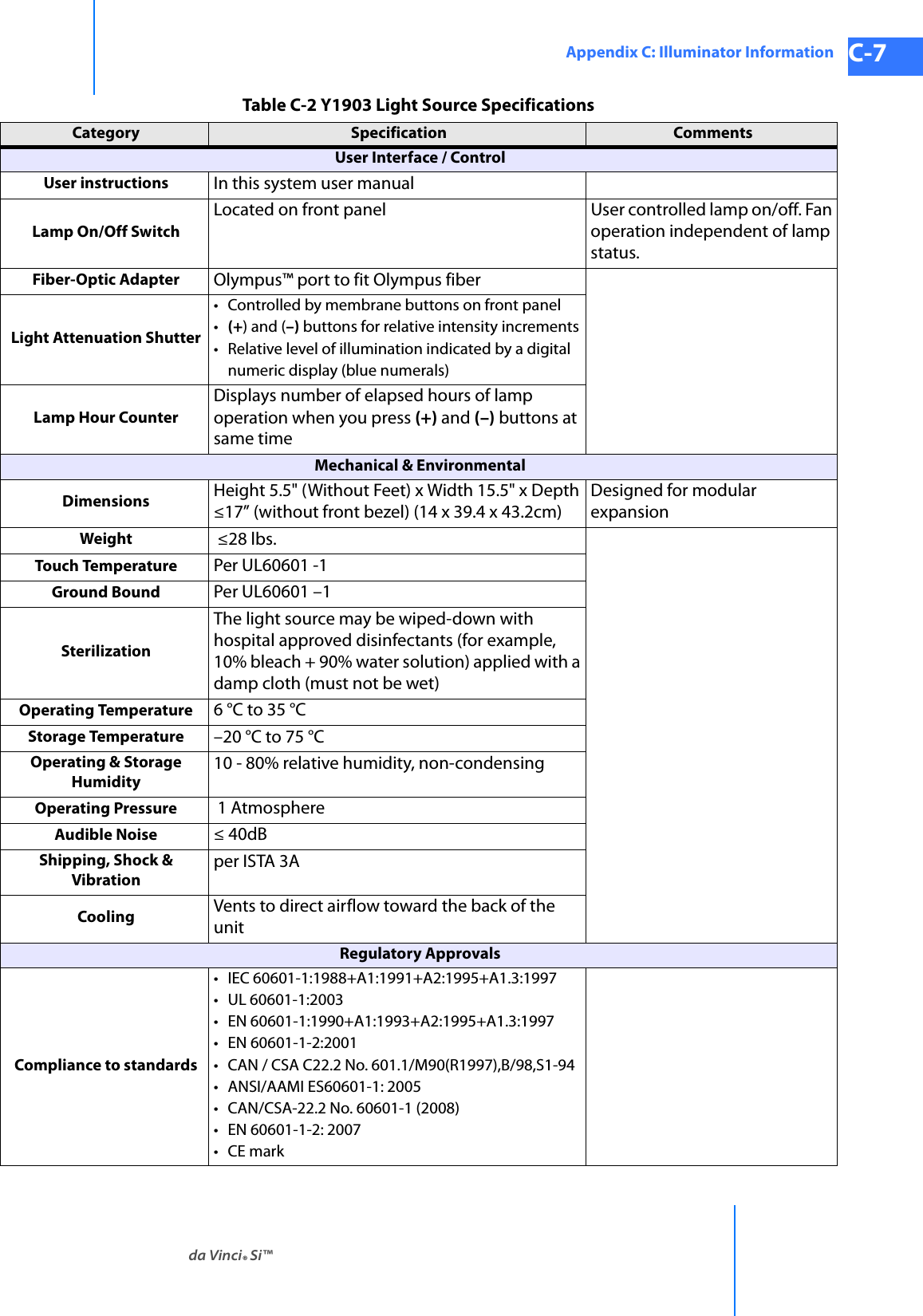
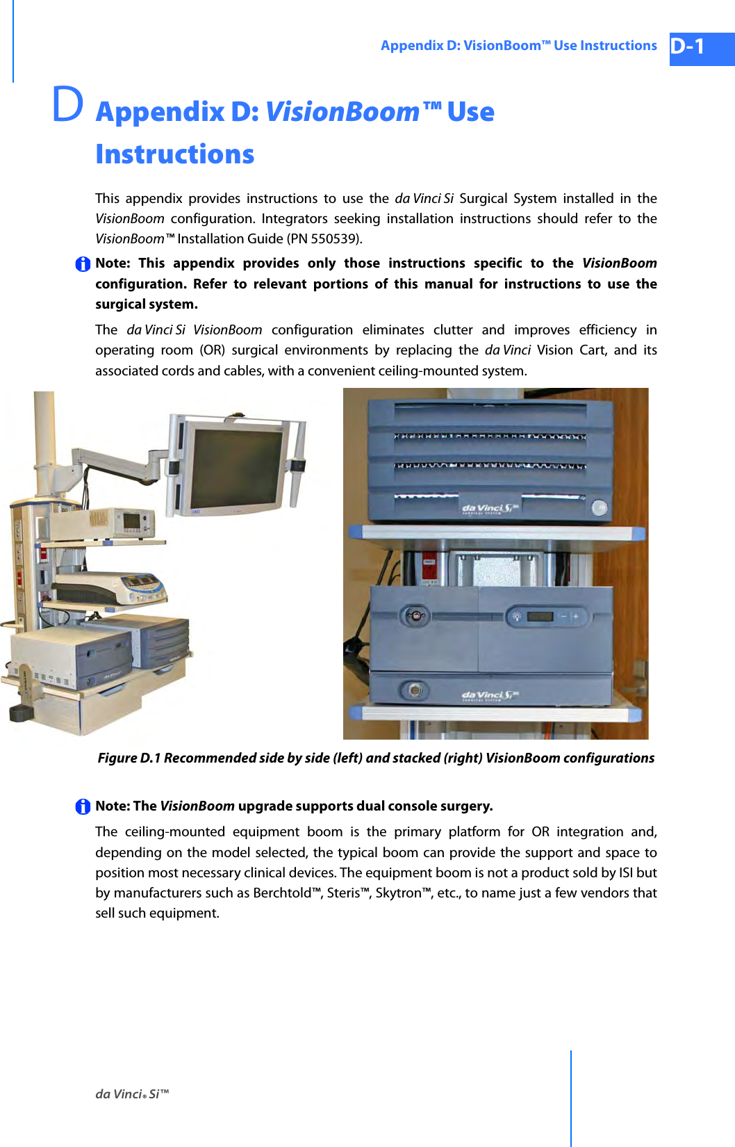
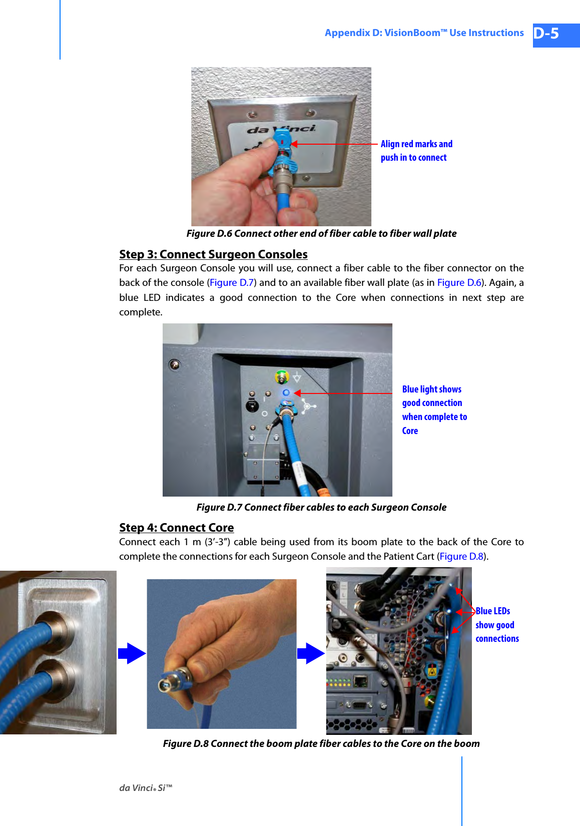
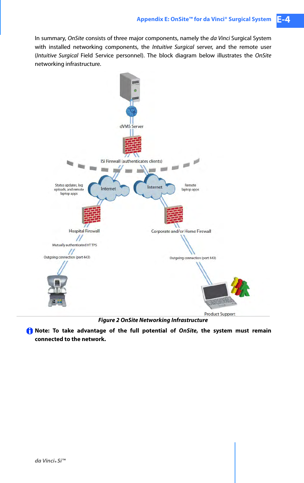
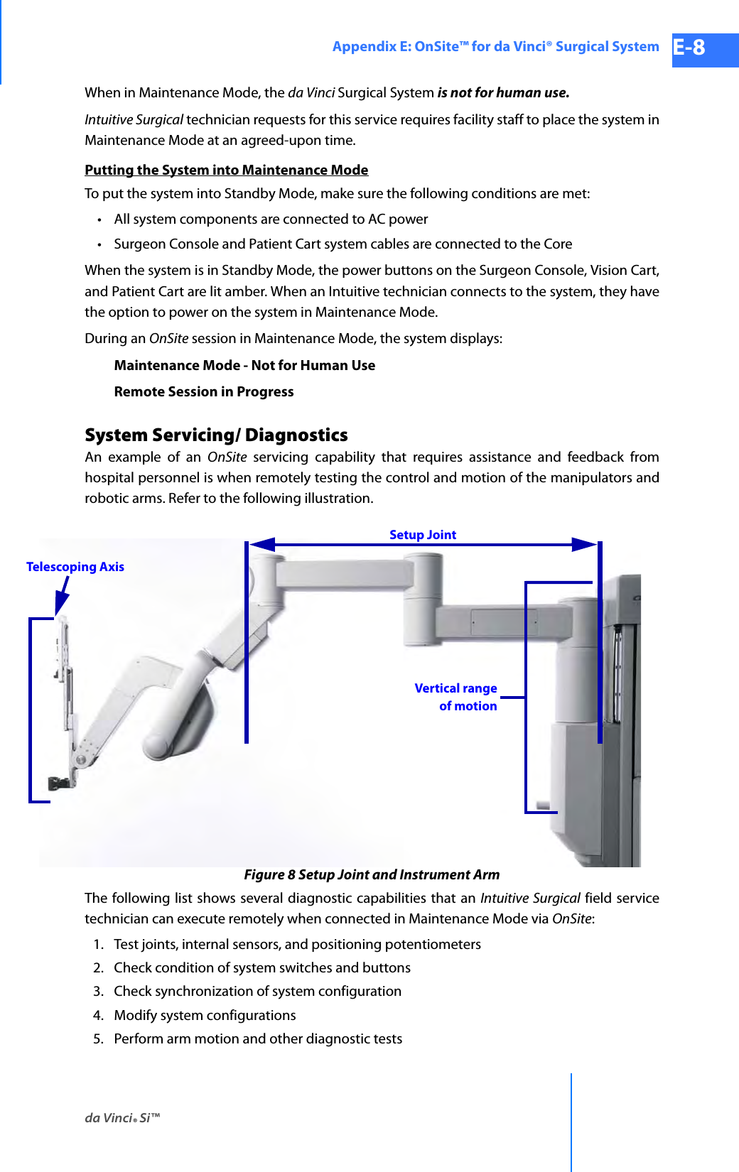
![da Vinci® Si™Appendix G: Symbols, Icons and Text Messages Reference G-31DRAFT/PRE-RELEASE/CONFIDENTIAL 10/9/14Non-recoverable Subsystem Fault <fault number>Non-recoverable Subsystem Fault <fault number>. Disable arm or restart system to continue.NormalNormal (2:1)Not availableNot connected to Vision Cart.OffOKOnOnSite Session in ProgressPage DownPage UpPatient cart and surgeon console either not connected or not powered.Patient cart battery is charging. Please wait.Patient Cart DisconnectedPatient cart either not connected or not powered.Patient cart running on battery. Check AC power.Patient-SidePatient-Side Touchscreen Failed Self-Test<Surgeon Console, Patient Side> Overlay [This is repeated in table for optional “Surgeon” and “Patient” starting letters.]Pedal Conflict.Remove conflicting instrument to enable.PendingPlease wait. Self-test in progressPreparing to Shut DownPress and Hold to Restore SettingsPress 'Arm Swap' pedal to activate arm.Press 'OK' to continuePress 'Recover Fault' or disable <name of manipulator; e.g., instrument arm 1, right master, etc.> to continuePress 'Recover Fault' or 'Disable Switches' to continue.Press 'Recover Fault' to continuePress 'Recover Fault' to continue. Contact customer service.Preventive maintenance recommended. Contact customer service.Previous LogQuick (1.5:1)RRecoverRecover FaultTable G-2 Text MessagesMessage](https://usermanual.wiki/Intuitive-Surgical/CHB01.User-Manual-Part-3/User-Guide-2607926-Page-83.png)
![Appendix G: Symbols, Icons and Text Messages Referenceda Vinci® Si™G-32DRAFT/PRE-RELEASE/CONFIDENTIAL10/9/14Recoverable FaultRecoverable Fault <fault number> Press 'Recover Fault' to continueRedRejectRelax hold on master so it can self-align.Remote Session in ProgressRemove InstrumentRestart system to continue.Restart system to continue. Contact customer service.Restore Factory SettingsRestore SettingsReverse<Left master, Right master> switches have been disabled by system. [This is repeated in table for optional “Left” and “Right” starting letters.]Right MasterRight video lost. Check video connections and power.Roll master grip.Rotate master to match instrument.ScalingScopeScope AngleSelect a motion scaling level.Select a scopeSelect a zoom levelSelect scope angle to continue.Service recommended. Contact customer service.Session AvailableSession EnabledSession EndedSession in ProgressSession UnavailableSet-up arm clutched at patient cart.Set-up arm moved unexpectedly. Press port clutch button to clear.Shutting down in <#> seconds. Press power button to cancel.SilenceSilence AlarmSizeSkip LoginSlide to unlockTable G-2 Text MessagesMessage](https://usermanual.wiki/Intuitive-Surgical/CHB01.User-Manual-Part-3/User-Guide-2607926-Page-84.png)
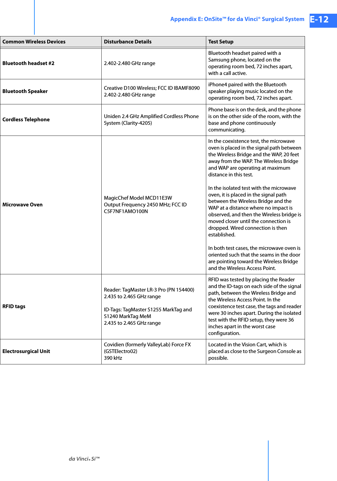
![da Vinci® Si™Appendix G: Symbols, Icons and Text Messages Reference G-33DRAFT/PRE-RELEASE/CONFIDENTIAL 10/9/14SmallSome ergonomic adjustments are unavailable.Start CalibrationStep <step number> of <total number of steps>: Press the center of the cursor.Stereo PairSuccessfulSurgeon ConsoleSurgeon console either not connected or not powered.<Surgeon Console, Patient Side> Overlay [This is repeated in table for optional “Surgeon” and “Patient” starting letters.]Surgeon Console Touchpad Is Not FunctionalSurgeon monitor tilt sensor error.Swap AllSwitch ErrorSystem communication failure. Restart system to continue.System Diagnostic Mode – Not for human use.System is overheating. Ensure adequate ventilation.System overheating. Shutting down in <#> seconds. Restart not possible; contact customer service.System shutting down.TakeTelestration EyeTest was run. Restart system for normal use.TFO Mode – Not for human use.the other console's left masterthe other console's right masterTileProTilePro QuickClickTouchscreen Calibration: <step number>/<total number of steps>Touchscreen is not available, but other system functions are unaffected. Press 'Recover Fault' to continue.Training instrument – Not for human useTraining scope – Not for human useTrial Software – Not for human useTroubleshootingUnknownUnlockUnsupported Parts Installed on SystemUse the da Vinci ergonomic controls on the left side pod to adjust the arm rest until your arms can rest comfortably with your shoulders relaxed.Table G-2 Text MessagesMessage](https://usermanual.wiki/Intuitive-Surgical/CHB01.User-Manual-Part-3/User-Guide-2607926-Page-85.png)