JADAK a business unit of Novanta H3 Bar Code Scanner and RFID Reader User Manual DR1000 04 20 05
SkyeTek, Inc. Bar Code Scanner and RFID Reader DR1000 04 20 05
UserManual.wiki
>
JADAK a business unit of Novanta
>
H3 User Manual
Users Manual
Navigation menu
Upload a User Manual
Namespaces
Wiki Guide
HTML
PDF
Info
Views
User Manual
Discussion / Help
Navigation


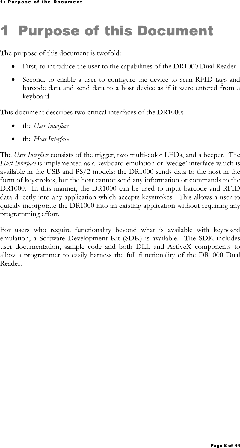
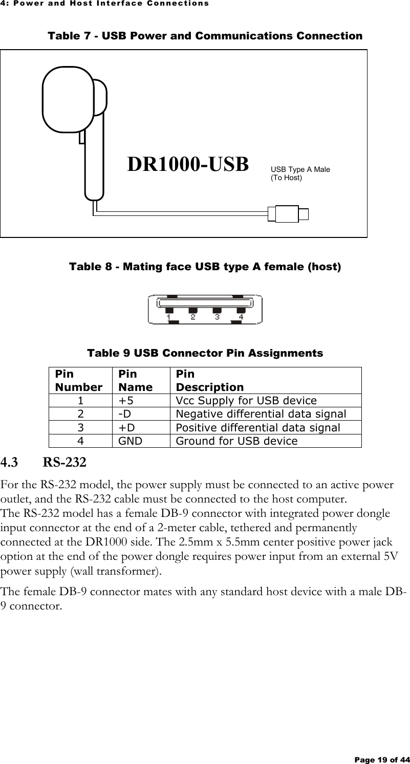
![3: Models & Modes of Operation Page 11 of 44 3 Models and Modes of Operation Table 3 lists the three available models and the corresponding modes of operation. The DR1000 has two (2) operating modes, Trigger Mode and Command Mode. Table 3 – DR1000 Models and Modes USB (Keyboard Emulation) 1 USB (Serial Emulation) 2 [default setting] RS-232 Serial PS/2 Trigger Mode 3 Keyboard emulation via USB ASCII data via virtual COM port ASCII data via RS-232 connector Keyboard emulation via PS/2 Connector Command Mode 4 N/A Via virtual COM port Via RS-232 connector Via RS-232 Connector Power Source Host USB connection Host USB connection External Power Supply Adaptor External Power Supply Adaptor or via the Host PS/2 interface 1 Keyboard emulation mode is automatically entered at power-on if the HID Mode is set to HID and the trigger is not pulled, or if HID Mode is set to Serial and the trigger is pulled at power-on and then released (USB model only). 2 Serial Emulation mode is automatically entered at power-on if the HID Mode is set to Serial and the trigger is not pulled, or if HID Mode is set to HID and the trigger is pulled at power-on and then released (USB model only). 3 Configurable ASCII read-only mode under DR1000 firmware control. 4 To configure the device for trigger mode operation and/or to perform read and write operations under application control. 3.1 Command Mode Command Mode is used to configure a device for trigger mode operation, and/or as the primary method to control the device. The BaRS utility software may be used to easily configure the DR1000 for keyboard emulation applications (see Appendix 1 for additional information). Host control of the DR1000 requires programming which is facilitated by the SDK (sold separately). As long as the DR1000 has power, Command Mode is active when the trigger is in the released position. In Command Mode the DR1000 is listening for a command from the host. It is not required that a host have the capability to send a command to the DR1000. NOTE The DR1000-PS/2 or DR1000 USB in keyboard emulation can never receive a command from a host. The DR1000 USB can receive commands if it is re-initialized in serial emulation mode. The DR1000-PS/2 can receive commands if its serial connector is plugged in. Writing to a tag can only be done in command mode.](https://usermanual.wiki/JADAK-a-business-unit-of-Novanta/H3/User-Guide-574602-Page-11.png)
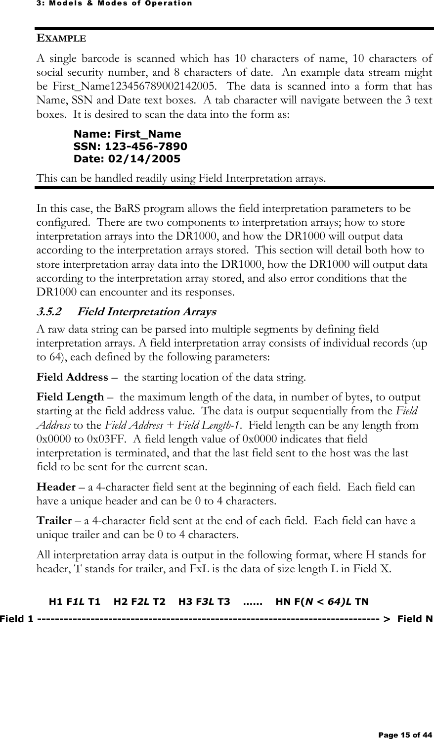
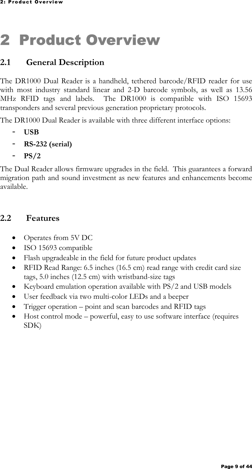
![3: Models & Modes of Operation Page 14 of 44 3.2.4 Keyboard Emulation (Wedge) In PS/2 or USB Keyboard Emulation Mode, the DR1000 will map each byte value of a data string to an equivalent keystroke. Only valid ASCII characters are output to the host. Any other barcode or RFID tag data not part of the ASCII character set is ignored. That is, the following ASCII values are discarded: SOH, STX, ETX, EOT, ENA, ACK, BEL, BS, VT, FF, SO, SI, DLE, DC1, DC2, DC3, DC4, NAK, SYN, ETB, CAN, EM, SUB, FS, GS, RS, US, DEL. Also, any byte value with the MSB set (high bit) is ignored. When a NUL character is encountered, the string is terminated and any additional characters are ignored. ASCII chart 0 1 2 3 4 5 6 7 8 9 A B C D E F 0 HT LF CR 1 ESC 2 SP ! " # $ % & ' ( ) * + , - . / 3 0 1 2 3 4 5 6 7 8 9 : ; < = > ? 4 @ A B C D E F G H I J K L M N O 5 P Q R S T U V W X Y Z [ \ ] ^ _ 6 ` a b c d e f g h i j k l m n o 7 p q r s t u v w x y z { | } ~ 3.3 Scanning an RFID Tag A RFID tag must be oriented parallel to the face of the DR1000 at no more than 5.0 inches for a wristband sized tag and 6.5 inches for a credit card sized tag. Upon a trigger pull, the DR1000 will scan for a RFID tag until a RFID tag is read or the trigger is released. The DR1000 outputs all data to the host as soon as it is read. However, the next scan cannot start until the trigger is released and pulled again. 3.4 Scanning a Barcode The proper method for scanning a barcode is to hold the face of the DR1000 4-6 inches from the barcode. When the trigger is depressed, a red or green light bar darker than the surrounding red laser appears on or over the barcode. The bar should line up with the barcode horizontally. The DR1000 continuously scans for a barcode until one is read or the trigger is released. 3.5 Field Interpretation 3.5.1 Overview Field Interpretation is a useful and powerful feature of the DR1000 to automatically parse a data string into multiple segments, or append fixed characters before or after a data string. This capability allows a user to automatically populate and navigate multiple text boxes in a form, simply by scanning a single barcode or RFID tag.](https://usermanual.wiki/JADAK-a-business-unit-of-Novanta/H3/User-Guide-574602-Page-14.png)