Japan Radio Co NKE1066 MARINE RADAR User Manual 5
Japan Radio Co Ltd. MARINE RADAR 5
UserManual.wiki
>
Japan Radio Co
>
NKE1066 User Manual
>
User Manual 5
Contents
1.
User Manual 1
2.
User Manual 2
3.
User Manual 3
4.
User Manual 4
5.
User Manual 5
User Manual 5
Navigation menu
Upload a User Manual
Namespaces
Wiki Guide
HTML
PDF
Info
Views
User Manual
Discussion / Help
Navigation


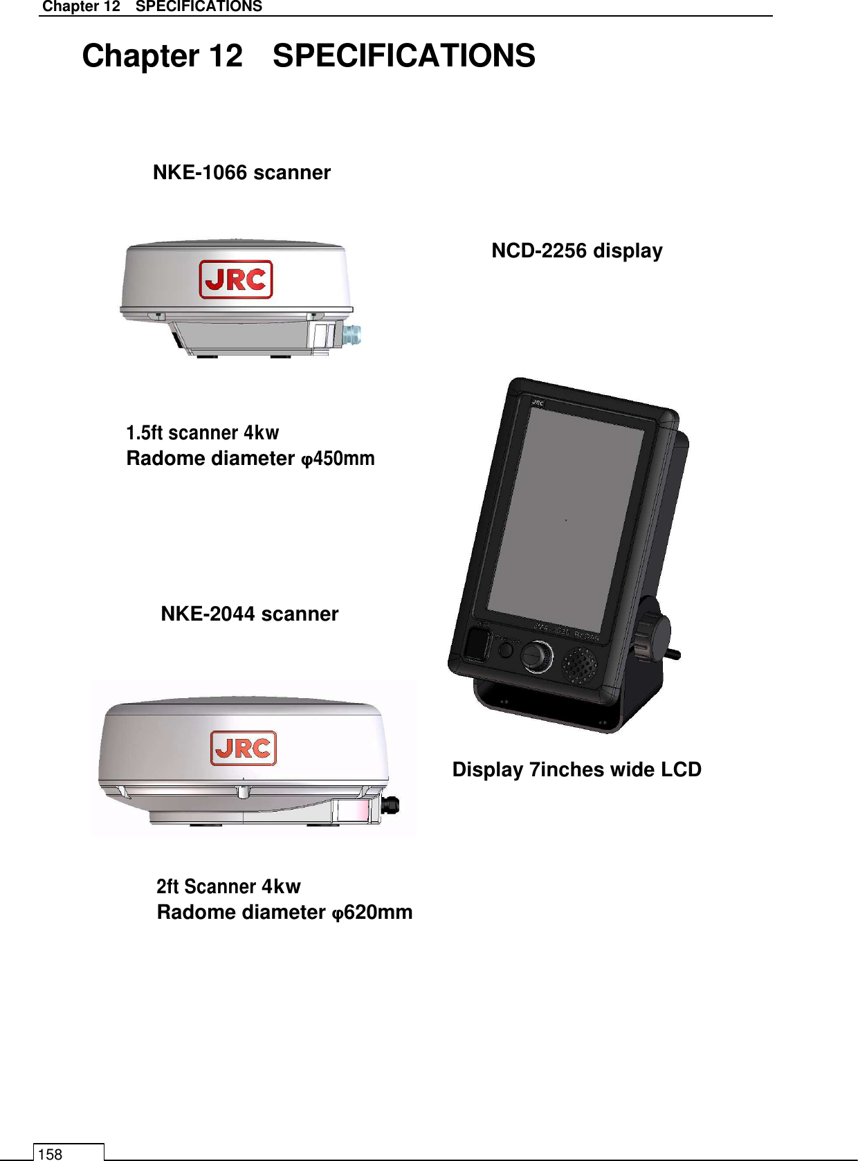
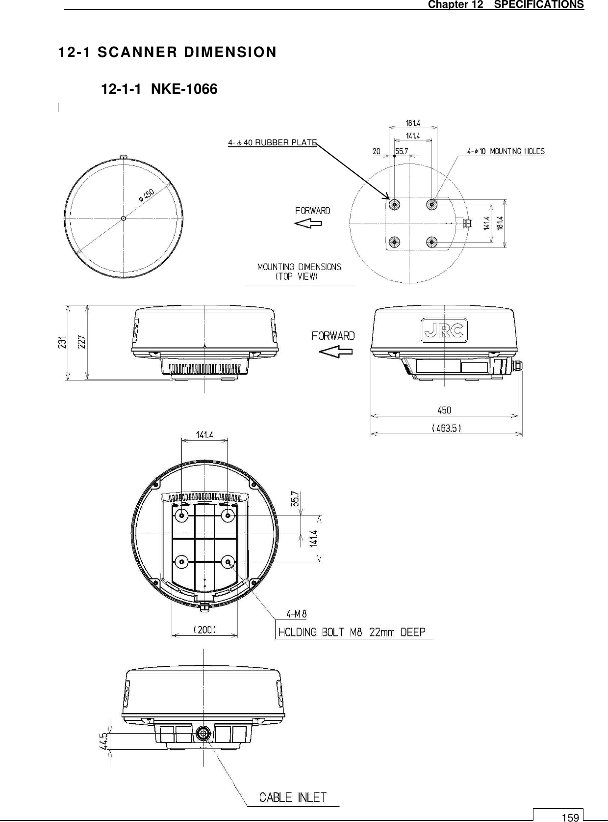
![Chapter 12 SPECIFICATIONS 166 12-5 SCANNER 12-5-1 SCANNER (NKE-1066) SPECIFICATION (1) Dimensions Height 231mm×Diameter of radome 450mm (2) Mass Approx. 5.5kg (3) Polarization Horizontal (antenna length 1.5 feet) (4) Antenna Directivity Horizontal Beam Width (-3dB) 5.2° Vertical Beam Width (-3dB) 25° Side lobe Level Less than -21dB (less than ±10° from the main lobe) (5) Rotation Approx. 27rpm (16/27/36/48rpm are available) (6) Transmitting Frequency 9410±30MHz (7) Peak Power 4 kW (8)Transmitting Tube Magnetron [M1624] (9) Pulse width/ Repetition Frequency (Bandwidth) SP1: 0.08µs/4000 Hz (Wide 20MHz) SP2: 0.08µs/2250 Hz (Wide 20MHz) SP3: 0.13µs/1700 Hz (Wide 20MHz) MP1: 0.25µs/1700 Hz (Middle 6MHz) MP2: 0.5µs/1200 Hz (Narrow 3MHz) LP1: 0.8µs/750 Hz (Narrow3 MHz) (S: Short pulse, M: Middle pulse, L: Long pulse) (10) Range Information 0.0625NM SP1 0.125NM SP1 0.25 NM SP1 0.5 NM SP1 / MP1 0.75 NM SP2 / MP1 1.5 NM SP2 / MP1 / MP2 3 NM SP3 / MP1 / MP2 6 NM MP2 / LP1 12 NM MP2 / LP1 24 NM LP1 (11) Duplexer Circulator + Diode Limiter (Diode Limiter is included in the frontend) (12) Front End Module MIC (13) IF Frequency 60MHz (14) IF AMP Log Amplifier (Gain: more than 90dB) (15) Overall Noise Figure 6dB(Average) (16) Tuning Manual/Auto](https://usermanual.wiki/Japan-Radio-Co/NKE1066.User-Manual-5/User-Guide-2183901-Page-29.png)
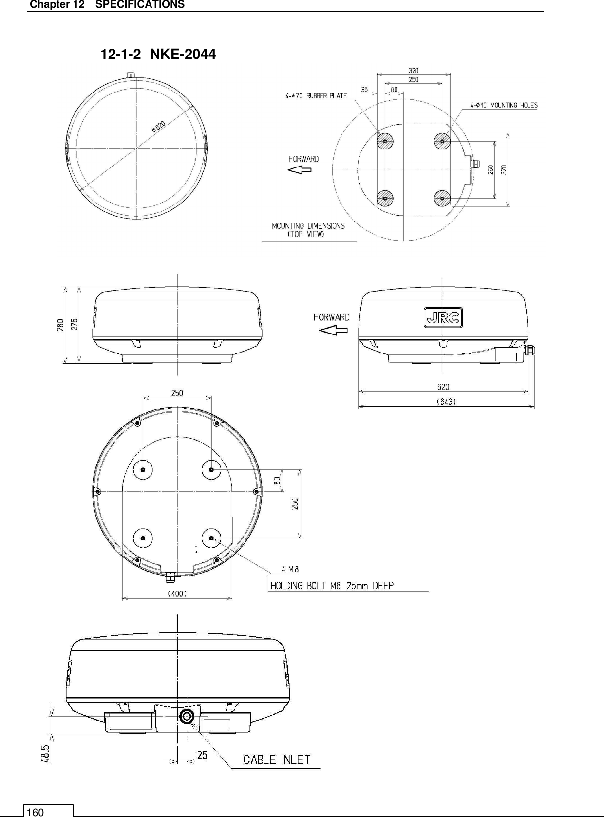
![Chapter 12 SPECIFICATIONS 167 12-5-2 SCANNER (NKE-2044) SPECIFICATION (1) Dimensions Height 280mm×Diameter of radome 620mm (2) Mass Approx. 10.5kg (3) Polarization Horizontal (antenna length 2 feet) (4) Directional Characteristic Horizontal Beam Width (-3dB) 4° Vertical Beam Width (-3dB) 25° Side lobe Level -21dB or less (less than ±10° from the main lobe) (5) Rotation Approx. 27rpm (16/27/36/48rpm are available) (6) Transmitting Frequency 9410±30MHz (7) Peak Power 4 kW (8)Transmitting Tube Magnetron [MSF1421B] (9) Pulse width/ Repetition Frequency (Bandwidth) SP1: 0.08µs/4000 Hz (Wide 20MHz) SP2: 0.08µs/2250 Hz (Wide 20MHz) SP3: 0.13µs/1700 Hz (Wide 20MHz) MP1: 0.25µs/1700 Hz (Middle 6MHz) MP2: 0.5µs/1200 Hz (Narrow 3MHz) LP1: 0.8µs/750 Hz (Narrow3 MHz) LP2:1.0us/650Hz (Narrow:3MHZ) (S: Short pulse, M: Middle pulse, L: Long pulse) (10) Range Information 0.0625NM SP1 0.125NM SP1 0.25 NM SP1 0.5 NM SP1 / MP1 0.75 NM SP2 / MP1 1.5 NM SP2 / MP1 / MP2 3 NM SP3 / MP1 / MP2 6 NM MP2 / LP1/ LP2 12 NM MP2 / LP1/ LP2 24 NM LP2 48 NM LP2 (11) Duplexer Circulator + Diode Limiter (12) Front End Module MIC (13) IF Frequency 60MHz (14) IF AMP Log Amplifier (Gain: more than 90dB) (15) Overall Noise Figure 6dB(Average) (16) Tuning Manual/Auto](https://usermanual.wiki/Japan-Radio-Co/NKE1066.User-Manual-5/User-Guide-2183901-Page-30.png)