Japan Radio NKE2062 MARINE RADAR User Manual 4
Japan Radio Co Ltd. MARINE RADAR Users Manual 4
UserManual.wiki
>
Japan Radio
>
NKE2062 User Manual
>
Users Manual 4
Contents
1.
Users Manual 1
2.
Users Manual 2
3.
Users Manual 3
4.
Users Manual 4
Users Manual 4
Navigation menu
Upload a User Manual
Namespaces
Wiki Guide
HTML
PDF
Info
Views
User Manual
Discussion / Help
Navigation
![7─11 7.2 NAVIGATOR SETTING This section describes the electrical adjustment procedures to be performed by service engineers during system installation. Make an appropriate setting for each type of equipment when inputting true bearing signals, true bearing data, and speed data. Settings and parameters are different for each type of equipment. Make settings for the type of equipment to be connected. [I] Inputting analog true bearing signals from a gyro system through synchronization and steps By following the procedure described in the INSTALLATION MANUAL, connect the optional NSK unit (NCT-4106A) to this equipment. Then, follow the steps below to make settings. In Section 7.2.1 “Ship Heading Equipment Setting (Heading Equipment),” select 1: GYRO (NCT-4106A, JLR10, JRL20/30). By referring to Section 7.2.2 “NSK Unit Setting,” make a setting for the gyro system. By referring to Section 7.2.3 “True Bearing Value Setting (Set GYRO),” make a setting such that the gyro azimuth and the radar azimuth are the same. Refer to an applicable page for details. CAUTION Do not carry out the adjustments of the equipment except authorized service persons. If wrong setting is carried out, this may cause unstable operation. Do not carry out the adjustments during navigation. Otherwise, the radar performance may be affected, resulting in an accident or trouble.](https://usermanual.wiki/Japan-Radio/NKE2062.Users-Manual-4/User-Guide-1377755-Page-1.png)
![7.2 NAVIGATOR SETTING 7─12 7yyyyyyy[II] Inputting digital true bearing signals from a gyro system (IEC61162, NMEA0183) By following the procedure described in the INSTALLATION MANUAL, connect the gyro system to this equipment. Then, follow the steps below to make settings. In Section 7.2.1 “Ship Heading Equipment Setting (Heading Equipment),” select 2: COMPASS (IEC61162). In Section 7.3.1.1 “Baud Rate Setting,” select 5. COM5 (COMPASS). Select either 38400 bps or 48000 bps depending on the data baud rate outputted from the GPS compass. (*) For digital signal output from the gyro system ・ Select 38400 bps if possible. A higher baud rate means shorter data output cycle, which results in better course following performance. ・ If the system allows setting of data output cycle, set it to 10 ms to 20 ms. A longer data output cycle results in lower course following performance. This may affect the radar performance level and the target tracking performance level. Refer to an applicable page for details. [III] Inputting true bearing data from GPS Compass JLR10 or JLR20/30 By following the procedure described in the INSTALLATION MANUAL, connect GPS Compass JLR10 or JLR20/30 to this equipment. Then, follow the steps below to make settings. In Section 7.2.1 “Ship Heading Equipment Setting (Heading Equipment),” select 1: GYRO (NCT-4106A, JLR10, JRL20/30). True bearing value setting described in Section 7.2.3 is not required when using the GPS compass. If the GPS compass azimuth and the radar azimuth are not the same, use the GPS compass to adjust the azimuth. Refer to an applicable page for details. [IV] Inputting digital true bearing data from a GPS compass (other than JLR10 and JLR20/30) or other true bearing systems (IEC61162 or NMEA0183) By following the procedure described in the INSTALLATION MANUAL, connect a GPS compass or other true bearing system to this equipment. Then, follow the steps below to make settings. In Section 7.2.1 “Ship Heading Equipment Setting (Heading Equipment),” select 2: COMPASS (IEC61162). In Section 7.3.1.1 “Baud Rate Setting,” select 5. COM5 (COMPASS). Select either 38400 bps or 48000 bps depending on the data baud rate outputted from the GPS compass. (*) For the GPS compass or other true bearing systems ・ Select 38400 bps if possible. A higher baud rate means shorter data output cycle, which results in better course following performance. ・ If the system allows setting of data output cycle, set it to 10 ms to 20 ms. A longer data output cycle results in lower course following performance. This may affect the radar performance level and the target tracking performance level. Refer to an applicable page for details.](https://usermanual.wiki/Japan-Radio/NKE2062.Users-Manual-4/User-Guide-1377755-Page-2.png)
![7─13 [V] Inputting analog speed signals from a log system through synchronization and steps By following the procedure described in the INSTALLATION MANUAL, connect the optional NSK unit (NCT-4106A) to this equipment. Then, follow the steps below to make settings. In Section 7.2.5 “Ship Speed Equipment Setting (Speed Equipment),” select 2: LOG. Refer to an applicable page for details. [VI] Inputting digital speed data using a current meter or a Doppler sonar (IEC61162 or NMEA0183) By following the procedure described in the INSTALLATION MANUAL, connect speed equipment to this equipment. Then, follow the steps below to make settings. In Section 7.2.5 “Ship Speed Equipment Setting (Speed Equipment),” select 3: 2 AXIS W to use the sea speed. Select 4: 2 AXIS G to use the ground speed. Refer to an applicable page for details. [VII] Inputting GPS speed data (IEC61162 or NMEA0183) By following the procedure described in the INSTALLATION MANUAL, connect speed equipment to this equipment. Then, follow the steps below to make settings. In Section 7.2.5 “Ship Speed Equipment Setting (Speed Equipment),” select 5: GPS. Refer to an applicable page for details. [VIII] Inputting speed data manually In Section 7.2.5 “Ship Speed Equipment Setting (Speed Equipment),” select 1: Manual. In Section 7.2.6 “Manual Speed Setting (Manual Speed),” input the speed manually using the numeric keypad or multi-dial. Refer to an applicable page for details.](https://usermanual.wiki/Japan-Radio/NKE2062.Users-Manual-4/User-Guide-1377755-Page-3.png)
![7.2 NAVIGATOR SETTING 7─14 7yyyyyyy7.2.1 Ship Heading Equipment Setting (Heading Equipment) Procedure 1 Press [RADAR MENU] key. Main Menu opens. 2 Press [7] key. NAV Equipment Setting menu opens. 3 Press [2] key. Heading Equipment settings are displayed. 4 From the pull-down menu, select heading equipment. 1 : GYRO (NCT-4106A, JLR10, JLR20/30) 2 : COMPASS (IEC61162) <The alternative procedure for steps above> 1 Hold down [RADAR MENU] key. The Code Input Menu will appear. 2 Press [0] key. 3 Move the cursor onto the “ENT” button in the Code Input menu, and press [ENT] key. The Adjust Menu will appear. 4 Press [6] key. NAV Equipment Setting menu opens. 5 Perform steps 3 and 4 in the “Procedure” above. Exit 1 Press [RADAR MENU] key. Menu closes.](https://usermanual.wiki/Japan-Radio/NKE2062.Users-Manual-4/User-Guide-1377755-Page-4.png)
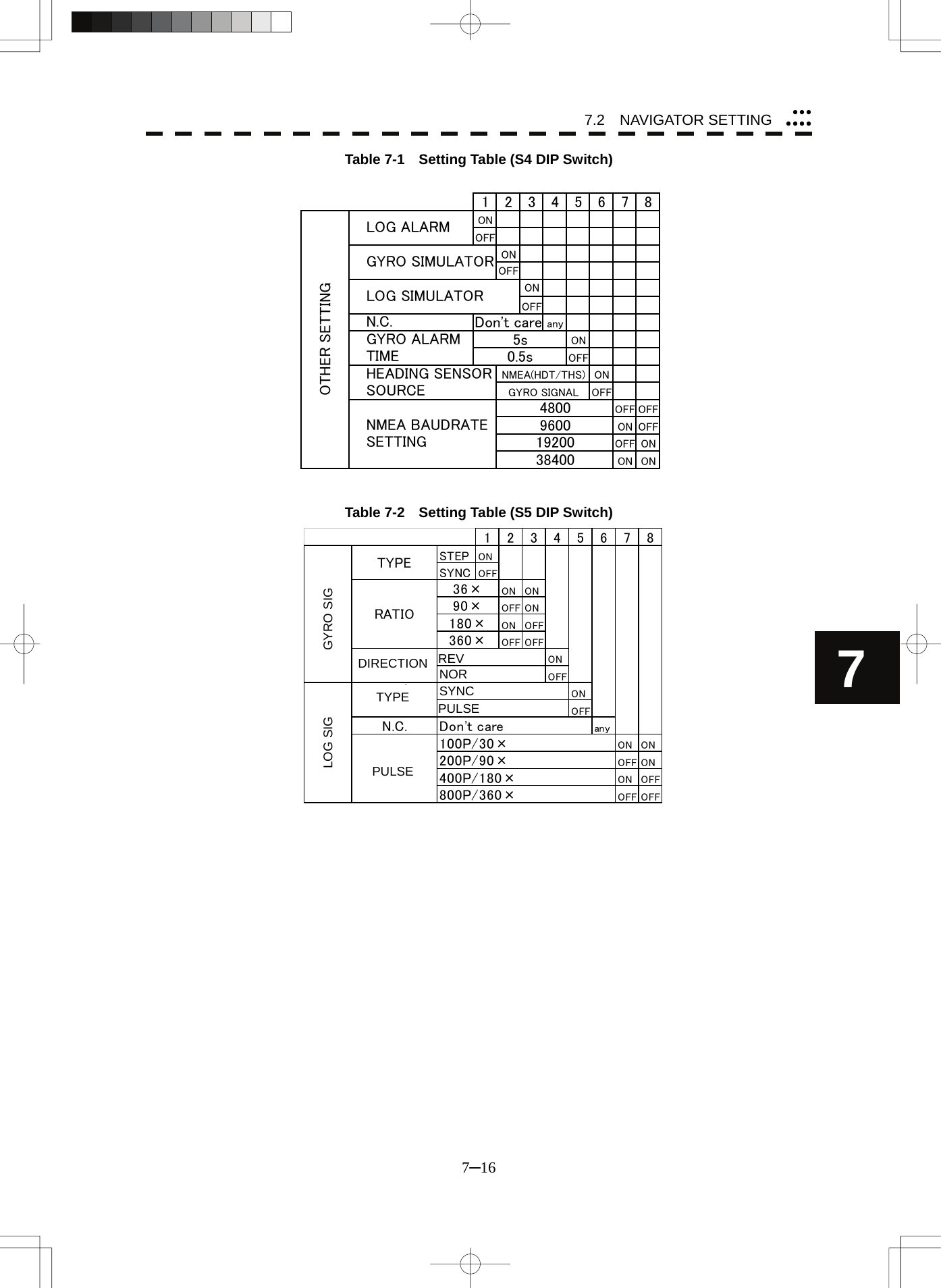
![7─15 7.2.2 NSK Unit Setting The NSK Unit circuit of the system is designed to be compatible with most types of gyro compasses by simply setting the switches. Step motor type: 20 to 170 VDC Synchro-motor type: Primary excitation voltage 35 to 120 VAC Before power-on operation can be performed, the switches S1 to S5 on the NSK Unit circuit (PC4201) must be set in accordance with the type of your gyro compass by performing the procedure below. The switches are factory-set for a gyration ratio of 180X and the step motor type. Make sure of the type of the gyro compass installed on the own ship before starting the procedure below. Procedure 1 Set S1 to "OFF." The gyro compass and NSK Unit are turned off. 2 Set S2 and S3 in accordance with the type of your gyro compass. There are two types of gyro compasses: one type outputs a step signal, and the other type outputs a synchro signal. Make sure of the type of the gyro compass installed on the own ship before setting the switches S2 and S3. Synchro signal: Set the switches to [SYNC]. Step signal: Set the switches to [STEP]. 3 Set the DIP switch S4. The items to be set are listed below. For the settings, refer to Table 7-1. S4-1: LOG alarm ON/OFF S4-2: GYRO simulator ON/OFF S4-3: LOG simulator ON/OFF S4-5: Time before occurrence of GYRO alarm S4-6: Sensor to be used (GYRO/NMEA) S4-7/8: Baud rate when NMEA is used 4 Set the DIP switch S5. The items to be set are listed below. For the setting, refer to Table 7-2. S5-1: Type of gyro signal (step/synchro) S5-2/3: Gyration ratio of gyro compass S5-4: Gyration direction of gyro compass S5-5: Type of log signal (pulse/synchro) S5-7/8: Ratio of log signal 5 Connect the gyro signal and log signal cables to the terminal block. 6 Set S1 to "ON." The gyro compass and NSK Unit are connected. 7 After power-on operation, set the true bearing according to Section 7.2.3. 8 Make sure of the radar video and the operation with the true bearing value. 9 If the true bearing value of the radar equipment is reversed, change the setting of the switch S5-4.](https://usermanual.wiki/Japan-Radio/NKE2062.Users-Manual-4/User-Guide-1377755-Page-5.png)
![7─17 7.2.3 True Bearing Value Setting (Set GYRO) Adjust the bearing that the bearing angle of the radar is the same as that of the gyro. When the NSK unit is used to input gyro signals, in rare cases, the true bearing value indicated by the master gyro and the true bearing value indicated by this equipment do not agree with each other. If this occurs, make the setting described below to adjust the true bearing value of this equipment to the value indicated by the master gyro. This setting is available only when the NSK unit NCT-4106A is used. Procedure 1 Press [RADAR MENU] key twice. The Main Menu will appear. 2 Press [7] key. The NAV Equipment Setting Menu will appear. 3 Press [1] key. The Code Input Menu will appear. 4 Adjust true bearing value. Adjust the bearing that the bearing angle of the radar is the same as that of the gyro. The multi-function control can also be used to enter the value. After having entered the value, move the cursor onto the “ENT” button and press [ENT] key. <The alternative procedure for steps above> 1 Hold down [RADAR MENU] key. The Code Input Menu will appear. 2 Press [0] key. 3 Move the cursor onto the “ENT” button in the Code Input menu, and press [ENT] key. The Adjust Menu will appear. 4 Press [6] key. NAV Equipment Setting menu opens. 5 Perform steps 3 and 4 in the “Procedure” above. Exit 1 Press [RADAR MENU] key. The menu will be closed.](https://usermanual.wiki/Japan-Radio/NKE2062.Users-Manual-4/User-Guide-1377755-Page-7.png)
![7.2 NAVIGATOR SETTING 7─18 7yyyyyyy7.2.4 MAG Compass Setting Set the MAG compass. Procedure 1 Press [RADAR MENU] key twice. The Main Menu will appear. 2 Press [7] key. NAV Equipment Setting Menu will appear. 3 Press [5] key. MAG Compass Setting Menu will appear. 4 Press [1] key. This item is set as to whether or not the heading bearing is to be corrected. Switching between ON and OFF is done each time you press [1] key. 5 Press [2] key. The Code Input Menu will appear. 6 Pressing a numeric key, enter the value. Select “ENT” and then determine the value. The correction direction and angle will be set. On the screen, press “+” to make correction in the eastern direction, and press “-” to make correction in the western direction. Also enter a correction angle, pressing the numeric key. The multi-function control is also available for the entry. To do so, enter the correction direction, press the multi-function control, enter the correction angle, and then set ENT in order. <The alternative procedure for steps above> 1 Hold down [RADAR MENU] key. The Code Input Menu will appear. 2 Press [0] key. 3 Move the cursor onto the “ENT” button in the Code Input menu, and press [ENT] key. The Adjust Menu will appear. 4 Press [6] key. NAV Equipment Setting menu opens. 5 Perform steps 3 to 6 in the “Procedure” above. Exit 1 Press [RADAR MENU] key. The menu will be closed.](https://usermanual.wiki/Japan-Radio/NKE2062.Users-Manual-4/User-Guide-1377755-Page-8.png)
![7─19 7.2.5 Ship Speed Equipment Setting (Speed Equipment) Procedure 1 Press [RADAR MENU] key twice. The Main Menu will appear. 2 Press [7] key. The NAV Equipment Setting Menu will appear. 3 Press [3] key. 4 Select a ship speed sensor from the pull-down menu. Types of selectable speed sensors: 1: Manual 2: Log 3: 2-axis log (NMEA signal: Speed over water) 4: 2-axis log (NMEA signal: Speed over ground) 5: GPS <The alternative procedure for steps above> 1 Hold down [RADAR MENU] key. The Code Input Menu will appear. 2 Press [0] key. 3 Move the cursor onto the “ENT” button in the Code Input menu, and press [ENT] key. The Adjust Menu will appear. 4 Press [6] key. NAV Equipment Setting menu opens. 5 Perform steps 3 and 4 in the “Procedure” above. Exit 1 Press [RADAR MENU] key. The menu will be closed. z The manually entered speed is effective only when “Manual” is set. z 2-axis log cannot be effective when the sentence VBW of NMEA0183 is not entered. Attention](https://usermanual.wiki/Japan-Radio/NKE2062.Users-Manual-4/User-Guide-1377755-Page-9.png)
![7.2 NAVIGATOR SETTING 7─20 7yyyyyyy7.2.6 Manual Speed Setting (Manual Speed) Procedure 1 Press [RADAR MENU] key twice. The Main Menu will appear. 2 Press [7] key. NAV Equipment Setting Menu will appear. 3 Press [4] key. The Code Input menu will appear. 4 Pressing a numeric key, enter the value and select “ENT.” The multi-function control is also available for the entry. <The alternative procedure for steps above> 1 Hold down [RADAR MENU] key. The Code Input Menu will appear. 2 Press [0] key. 3 Move the cursor onto the “ENT” button in the Code Input menu, and press [ENT] key. The Adjust Menu will appear. 4 Press [6] key. NAV Equipment Setting menu opens. 5 Perform steps 3 and 4 in the “Procedure” above. Note: The manually entered speed is effective only when “Manual” is set.](https://usermanual.wiki/Japan-Radio/NKE2062.Users-Manual-4/User-Guide-1377755-Page-10.png)
![7─21 7.2.7 Current Correction (SET/DRIFT) Setting The current set and drift will be set. Procedure 1 Press [RADAR MENU] key twice. The Main Menu will appear. 2 Press [7] key. The NAV Equipment Setting Menu will appear. 3 Press [6] key. The Set/Drift Setting Menu will appear. 4 Press [1] key to enable Correction. The setting of Correction is switched back and forth between ON and OFF each time [1] key is pressed. Off : Do not perform current correction. On : Perform current correction. 5 Press [2] key. The Code Input Menu will appear. 6 Enter the direction of tendency. The direction of tendency will be set. The multi-function control is also available for the entry. After having entered the direction, move the cursor onto the “ENT” button and press [ENT] key. 7 Press [3] key. The Code Input Menu will appear. 8 Enter the speed of tendency. The speed of tendency will be set. The multi-function control is also available for the entry. After having enter the value, move the cursor onto the “ENT” button and press [ENT] key. z The manually entered speed is effective only when “Speed Equipment” is set to “Manual” or “LOG”. Attention](https://usermanual.wiki/Japan-Radio/NKE2062.Users-Manual-4/User-Guide-1377755-Page-11.png)
![7.2 NAVIGATOR SETTING 7─22 7yyyyyyy <The alternative procedure for steps above> 1 Hold down [RADAR MENU] key. The Code Input Menu will appear. 2 Press [0] key. 3 Move the cursor onto the “ENT” button in the Code Input menu, and press [ENT] key. The Adjust Menu will appear. 4 Press [6] key. NAV Equipment Setting menu opens. 5 Perform steps 3 to 8 in the “Procedure” above. Exit 1 Press [RADAR MENU] key. The menu will be closed.](https://usermanual.wiki/Japan-Radio/NKE2062.Users-Manual-4/User-Guide-1377755-Page-12.png)
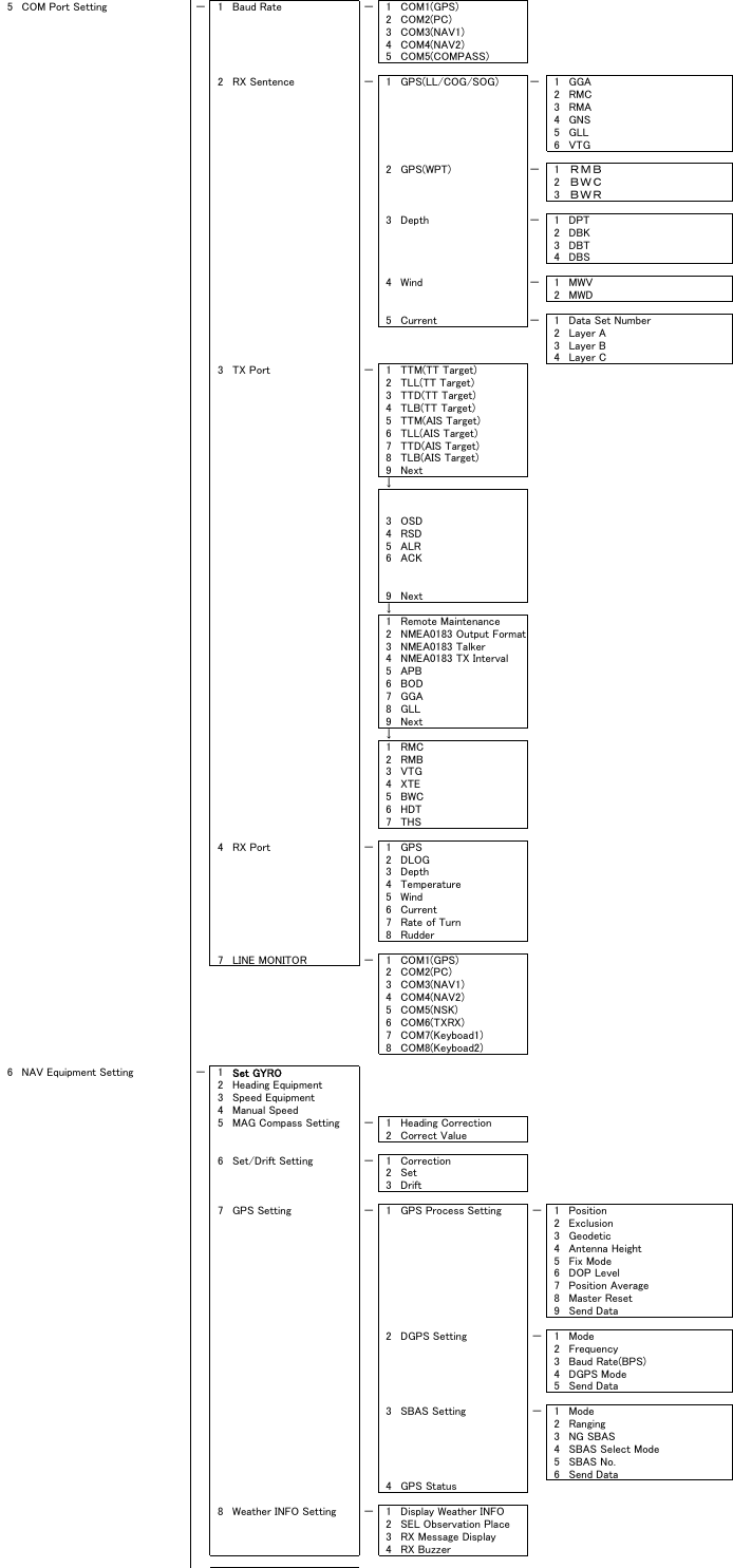
![7.3 SETTINGS 7─24 7yyyyyyy7.3.1.1 Baud Rate Setting Set the baud rate of the signal to be entered into the COM port. Each ports on the menu represents following connectors. COM1(GPS) J3 GPS COM2(PC) J8 NMEA COM3(NAV1) J6 AIS/NMEA COM4(NAV2) J9 AUX COM5(NSK/COMPASS) J5 GYRO COMPASS Procedure 1 Hold down [RADAR MENU] key. The Code Input Menu will appear. 2 Press [0] key. 3 Move the cursor onto the “ENT” button in the Code Input menu, and press [ENT] key. The Adjust Menu will appear. 4 Press [5] key. The COM Port Setting Menu will appear. 5 Press [1] key. The Baud Rate Setting Menu will appear. 6 Select the port number you want to set, pressing the numeric keys [1] to [5]. The Baud Rate Selection menu will appear. 7 In the selection menu, select the baud rate you want to set, pressing the numeric key. Selection value 1. COM1 (GPS): 1200/4800/*38400/9600 bps 2. COM2 (PC): 1200/4800/38400/115200/9600 bps 3. COM3 (NAV1): 1200/4800/38400/9600 bps 4. COM4 (NAV2): 1200/4800/*38400/9600 bps 5. COM5 (COMPASS): 4800/38400 bps * If COM1/COM4 is set to 38400 bps, signals can only be transmitted. The baud rate for reception can be set to up to 4800 bps. COM5 can be used for receive port only. It is dedicated for COMPASS signal. This means that the port is unavailable for other signals. The GPS, PC, NAV1, NAV2, COMPASS in the parentheses are the standard ports connecting to the external sensors. When an AIS unit is used, COM3 is used exclusively for the AIS. Connect the AIS to COM3. Use a port other than COM3 when connecting a device other than an AIS unit. An external device can be connected to COM3 when an AIS unit is not used. When a baud rate of 1200 bps is selected, a 1200 bps JRC format is used.](https://usermanual.wiki/Japan-Radio/NKE2062.Users-Manual-4/User-Guide-1377755-Page-14.png)
![7─25 Exit 1 Press [RADAR MENU] key. The Main Menu will reappear.](https://usermanual.wiki/Japan-Radio/NKE2062.Users-Manual-4/User-Guide-1377755-Page-15.png)
![7.3 SETTINGS 7─26 7yyyyyyy7.3.1.2 Reception Port Setting (RX Port) Set the number of the port via which signals are received from sensors. There are two methods for receiving signals: specifying a port for each sensor, or using the automatic recognition function without specifying ports. Procedure 1 Hold down [RADAR MENU] key. The Code Input Menu will appear. 2 Press [0] key. 3 Move the cursor onto the “ENT” button in the Code Input menu, and press [ENT] key. The Adjust Menu will appear. 4 Press [5] key. The COM Port Setting Menu will appear. 5 Press [4] key. The RX Port Menu will appear. 6 Select the signal you want to set, pressing the numeric keys [1] to [6]. The Reception Port Setting Menu for each signal will appear. Settable signals 1. GPS 2. DLOG 3. Depth 4. Temperature 5. Wind 6. Current 7. Rate of Turn 8. Rudder 7 Select which port you want to use for output. Types of ports to be used 1. AUTO 2. COM1 (GPS) 3. COM2 (PC) 4. COM3 (NAV1) 5. COM4 (NAV2) * For AUTO, the initial value will be selected. Select the number of the port to be used, pressing the numeric key. Exit 1 Press [RADAR MENU] key. The Main Menu will reappear.](https://usermanual.wiki/Japan-Radio/NKE2062.Users-Manual-4/User-Guide-1377755-Page-16.png)
![7─27 7.3.1.3 Reception Sentence Setting (RX Sentence) Set signal sentences to be received from sensors. Procedure 1 Hold down [RADAR MENU] key. The Code Input Menu will appear. 2 Press [0] key. 3 Move the cursor onto the “ENT” button in the Code Input menu, and press [ENT] key. The Adjust Menu will appear. 4 Press [5] key. The COM Port Setting Menu will appear. 5 Press [2] key. The RX Sentence Menu will appear. 6 Select the signal you want to set, pressing the numeric keys [1] to [3]. The Setting Menu for each signal will appear. Settable signal 1. GPS (LL/COG/SOG) 2. GPS (WPT) 3. Depth 4. Wind 5. Current 7 Select whether or not you want to use sentence for the signal. Types of sentences to be used GPS (LL/COG/SOG): GGA/RMC/RMA/GNS/ GLL/VTG GPS (WPT): GGA/RMC/RMB/ BWC/BWR/ZDA Depth: DPT/DBK/DBT/DBS Wind: MWV/MWD Current: CUR After having selected a signal, choose the number of the sentence for which you want to set whether or not it is used, pressing the numeric key. As concerns current, set layer number of CUR sentence. ↓](https://usermanual.wiki/Japan-Radio/NKE2062.Users-Manual-4/User-Guide-1377755-Page-17.png)
![7.3 SETTINGS 7─28 7yyyyyyy Layer A: 0-999. Set the number of the sentence to be used with layer A by Layer Number. (Initial value 3) Layer B: 0-999. Set the number of the sentence to be used with layer B by Layer Number. (Initial value 4) Layer C: 0-999. Set the number of the sentence to be used with layer C by Layer Number. (Initial value 5) Exit 1 Press [RADAR MENU] key. The Main Menu will reappear.](https://usermanual.wiki/Japan-Radio/NKE2062.Users-Manual-4/User-Guide-1377755-Page-18.png)
![7─29 7.3.1.4 Transmission Port Setting (TX Port) For each sentence, set a communication port through which signals are transmitted to sensors. Procedure 1 Hold down [RADAR MENU] key. The Code Input Menu will appear. 2 Press [0] key. 3 Move the cursor onto the “ENT” button in the Code Input menu, and press [ENT] key. The Adjust Menu will appear. 4 Press [5] key. Press [3] key. The TX Port Menu will appear. 5 Select the signal you want to set, pressing the numeric keys [1] to [9]. The Output Port Setting Menu for each signal will appear. Settable sentences 1. TTM(TT Target) 2. TLL(TT Target) 3. TTD(TT Target) 4. TLB(TT Target) 5. TTM(AIS Target) 6. TLL(AIS Target) 7. TTD(AIS Target) 8. TLB(AIS Target) ↓ 1. 2. 3. OSD 4. RSD 5. ALR 6. AIS 7. 8. ↓ 1. Remote Maintenance 2. NMEA0183 Output Format 3. NMEA0183 Talker 4. NMEA0183 TX Interval 5. APB 6. BOD 7. GGA 8. GLL ↓ 1. RMC 2. RMB 3. VTG 4. XTE 5. BWC](https://usermanual.wiki/Japan-Radio/NKE2062.Users-Manual-4/User-Guide-1377755-Page-19.png)
![7.3 SETTINGS 7─30 7yyyyyyy6. HDT 7. THS 6 Select which port you want to use for output. Types of ports to be used 1. OFF 2. COM1 (GPS) 3. COM2 (PC) 4. COM3 (NAV1) 5. COM4 (NAV2) Select the number of the port to be used, pressing the numeric key. 7 Select the output format, talker, and transmission interval. Signals for which the above items can be set: • NMEA0183 Output Format Signal names: APB, BOD, GGA, GLL, RMC, RMB,VTG, XTE, BWC, HDT, THS Selection Value: V1.5, V2.0, and V2.3 • NMEA0183 Talker Signal names: APB, BOD,RMB, XTE, BWC, HDT, THS Selection Value: Standard: The talker is RA. GP: The talker is GP. For TTM, TLL, TTD, TLB, OSD, RSD, ALR, and AIS, the talker is always RA . For GGA, GLL, RMC, and VTG, the talker is always GP. • NMEA0183 TX Interval Signal names: APB, BOD, GGA, GLL, RMC, RMB,VTG, XTE, BWC, HDT, THS Selection Value: Set an interval in the range 1 to 9 seconds. Note: When multiple output sentences are selected, data may not be transmitted at the selected transmission interval. In particular, the volume of TTM, TLL, TLB, and TTD data containing TT and AIS target information increases as the number of targets increases, and as a result, the transmission interval becomes longer. Exit 1 Press [RADAR MENU] key. The Main Menu will reappear. * Note that, if you set COM1 and COM4 for transmission, they cannot be used as reception ports.](https://usermanual.wiki/Japan-Radio/NKE2062.Users-Manual-4/User-Guide-1377755-Page-20.png)
![7─31 7.3.2 Sector Blank Setting (Sector Blank) Set a sector range, preventing displaying the radar echo only within the area. Three types of sector can be created. The sector blank function operates in the relative bearing with the bow. Note: This function can be performed only when the scanner is connected to NKE-2103 and NKE-2254. [I] Turning ON/OFF the Sector function (Sector 1, 2 and 3) Procedure 1 Hold down [RADAR MENU] key. The Code Input Menu will appear. 2 Press [0] key. 3 Move the cursor onto the “ENT” button in the Code Input menu, and press [ENT] key. The Adjust Menu will appear. 4 Press [4] key. Press [6] key. The Sector Blank Menu will appear. 5 Select the number you want to excuted sector blank, Pressing the numeric keys [1] to [3]. The system allows the use of up to three sector blank areas. Set each sector blank area to on or off. On: The sector blank function is operated. Off: The sector blank function is stopped. Exit 1 Press [RADAR MENU] key. The Main Menu will reappear.](https://usermanual.wiki/Japan-Radio/NKE2062.Users-Manual-4/User-Guide-1377755-Page-21.png)
![7.3 SETTINGS 7─32 7yyyyyyy[II] Making Sector Function (Make Sector 1, 2, 3) Procedure 1 Transmit the radar. 2 Hold down [RADAR MENU] key. The Code Input Menu will appear. 3 Press [0] key. 4 Move the cursor onto the “ENT” button in the Code Input menu, and press [ENT] key. The Adjust Menu will appear. 4 Press [4] key. Press [6] key. The Sector Blank Menu will appear. 5 Slect the number you want to make sector blank, pressing the numeric keys [4] to [6]. The sector blank for the numeric key pressed will be made. 6 Set the start point of the sector blank by operating the [EBL] dial, and then press 7 ENT. The start angle of the sector blank will be set. 7 Set the end point of the sector blank by operating the [EBL] dial, and then press 7 ENT. The end angle of the sector blank will be set. Exit 1 Press [RADAR MENU] key. The Main Menu will reappear.](https://usermanual.wiki/Japan-Radio/NKE2062.Users-Manual-4/User-Guide-1377755-Page-22.png)
![7─33 7.3.3 TNI Blank Setting (TNI Blank) Set a sector and stop tuning operation in the bearing. If a structure such as the mast is close to the radar antenna, automatic tuning operation may become unstable. In this case, set a TNI blank in the direction of the structure in order to stabilize the tuning operation. Only one TNI blank sector can be created. The TNI blank function operates in the relative bearing with the bow. Note: This function can be performed only when the scanner is connected to NKE-2103 and NKE-2254. [I] TNI Blank Function On/Off (Sector) Procedure 1 Hold down [RADAR MENU] key. The Code Input Menu will appear. 2 Press [0] key. 3 Move the cursor onto the “ENT” button in the Code Input menu, and press [ENT] key. The Adjust Menu will appear. 4 Press the following keys. 4 TXRX Setting 9 TNI Blank 1 TNI Blank On: The TNI blank function is operated. Off: The TNI blank function is stopped.](https://usermanual.wiki/Japan-Radio/NKE2062.Users-Manual-4/User-Guide-1377755-Page-23.png)
![7.3 SETTINGS 7─34 7yyyyyyy[II] TNI Blank Area Creation (Make Sector) Procedure 1. Transmit the radar. 2 Hold down [RADAR MENU] key. The Code Input Menu will appear. 3 Press [0] key. 4 Move the cursor onto the “ENT” button in the Code Input menu, and press [ENT] key. The Adjust Menu will appear. 5 Press the following keys. 4 TXRX Setting 9 TNI Blank 2 Create sector 6 Set the starting bearing of the TNI blank by operating the [EBL] dial, and press the [ENT] key. 7 Set the ending bearing of the TNI blank by operating the [EBL] dial, and press the [ENT] key. The TNI blank area is set.](https://usermanual.wiki/Japan-Radio/NKE2062.Users-Manual-4/User-Guide-1377755-Page-24.png)
![7─35 7.3.4 Bearing Pulse Output Adjustment (Output Pulse) Set the output value of bearing pulse. This radar can set the output value to 2048 pulses and 4096 pulses. This setting is allowed only when a 25 kw antenna is used. Procedure 1 Hold down [RADAR MENU] key. The Code Input Menu will appear. 2 Press [0] key. 3 Move the cursor onto the “ENT” button in the Code Input menu, and press [ENT] key. The Adjust Menu will appear. 4 Press [4] key. The TXRX Setting Menu will appear. 5 Press [7] key. 6 Select a set value to be used. Exit 1 Press [RADAR MENU] key. The Main Menu will reappear.](https://usermanual.wiki/Japan-Radio/NKE2062.Users-Manual-4/User-Guide-1377755-Page-25.png)
![7.3 SETTINGS 7─36 7yyyyyyy7.3.5 Language Setting (Language) You can switch between Japanese and English. Procedure 1 Hold down [RADAR MENU] key. The Code Input Menu will appear. 2 Press [0] key. 3 Move the cursor onto the “ENT” button in the Code Input menu, and press [ENT] key. The Adjust Menu will appear. 4 Press [1]. The Equipment Setup window will appear. 5 Select the language you want to display, pressing the numeric keys [1] to [3]. 1. English 2. Japanese 3. Other “Other” in 3. is a language corresponding to characters created in overseas agents. To confirm whether or not your language is supported, contact overseas agents or our sales department. To make the set language effective, turn off the power supply and then restart. Exit 1 Press [RADAR MENU] key. The Main Menu will reappear.](https://usermanual.wiki/Japan-Radio/NKE2062.Users-Manual-4/User-Guide-1377755-Page-26.png)
![7─37 7.3.6 Date/Time Display Setting (Date/Time Setting) In displaying the time, it is necessary to set the LOCAL TIME, LOCAL DATE and TIME ZONE. When the “ZDA” sentence of NMEA0183 is received, Date/Time is displayed automatically. * If “ZDA” sentence is not received, the system internal clock function is used to display the date and time. Procedure 1 Press [RADAR MENU] key twice. The RADAR Menu will appear. 2 Open the following windows. 8 Open the Radar Sub Menu window. 4 Open the Data/Time Setting window. 3 Set information about date and time. [1] UTC/LMT (Time display system) Press [1] to switch the time mode between: UTC: Universal Time Coordinate LMT: Local Time [2] LMT Date Input the date in local time. Press [2] key and call up the numeric keypad. Input the date using the numeric keypad or the multi-dial. Then, press [ENT] button. [3] LMT Time Input the time in local time. Input the time using the numeric keypad or the multi-dial. Then, press [ENT] button. [4] Time Zone Input the time-zone difference between the universal time and local time. Input the time difference using the numeric keypad or the multi-dial. Then, press [ENT] button. [5] Display Style Set one of the following date display formats. Press [5] key and select a date display format. YYYY-MM-DD Example: 2007-12-31 MMM DD, YYYY Example: Dec 31, 2007 DD MMM, YYYY Example: 31 Dec, 2007 Exit 1 Press [RADAR MENU] key. The menu will be closed. z The “ZDA” sentence of NMEA0183 take presedence of the above setting. Attention](https://usermanual.wiki/Japan-Radio/NKE2062.Users-Manual-4/User-Guide-1377755-Page-27.png)
![7─39 7.4.1 Noise Level Adjustment (Noise Level) [I] Noise Level Adjustment for Signal Processing Procedure 1 Hold down [RADAR MENU] key. The Code Input Menu will appear. 2 Press [0] key. 3 Move the cursor onto the “ENT” button in the Code Input menu, and press [ENT] key. The Adjust Menu will appear. 4 When the Adjust Menu appears, press [8] key. The SP/TT INIT Setup Menu will appear. 5 Press [1] key. The Noise Level Menu will appear. 6 Press [1] key. The Code Input Menu will open to change the noise level value. 7 Change the value to display echo correctly. In addition to the entry on the Code Input menu, the Multi-functional Dial Control is available to change the value. Note: The noise level is factory-set. After system installation, a great change in the noise level adjustment value should be avoided; it should be fine adjusted within ±5. Exit 1 Press [RADAR MENU] key. The Main Menu will reappear.](https://usermanual.wiki/Japan-Radio/NKE2062.Users-Manual-4/User-Guide-1377755-Page-29.png)
![7.4 ADJUSTMENT 7─40 7yyyyyyy[II] Noise Level Adjustment Mode (Setting Mode) Procedure 1 Hold down [RADAR MENU] key. The Code Input Menu will appear. 2 Press [0] key. 3 Move the cursor onto the “ENT” button in the Code Input menu, and press [ENT] key. The Adjust Menu will appear. 4 When the Adjust Menu appears, press [8] key. The SP/TT INIT Setup Menu will appear. 5 Press [1] key. Noise Level Menu will appear. 6 Press [2] key. The noise level adjustment mode is switched between on and off. Factory-adjustment method • The GAIN control is set to the maximum position, the SEA control is set to the minimum position, the RAIN control is set to the minimum position, and IR, AUTO-SEA, AUTO-RAIN, PROC, FUNC, and TRAILS are all set to off. • The noise level adjustment mode is turned on. • While the noise level adjustment value is decreased gradually, the value with which radar echoes no longer appear is determined as the set value. • Ten is added to the set value (with which radar echoes no longer appear), and the result is set as the final noise level adjustment value. • The noise level adjustment mode is turned off when the adjustment is finished. Exit 1 Press [RADAR MENU] key. The Main Menu will reappear.](https://usermanual.wiki/Japan-Radio/NKE2062.Users-Manual-4/User-Guide-1377755-Page-30.png)
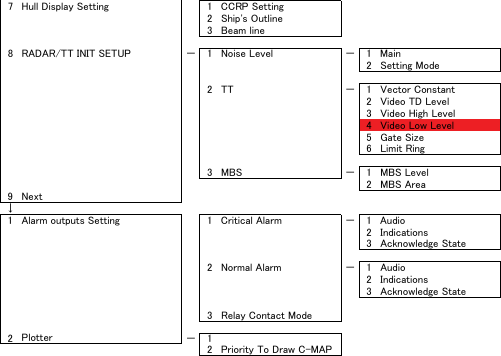
![7─41 7.4.2 Adjustment of Target Tracking Function (TT) [I] Vector Constant Adjustment (Vector Constant) Adjust the vector follow-up performance of the target tracking function. The vector constant is adjusted to an optimal value, so do not change it carelessly. z Do not change the set value carelessly. The vector constant shall be set to 4 normally. If the vector constant value is higher, a target’s vector will be better followed up when the target and own ship change their course or speed, but the vector accuracy will be lower on the contrary. Attention CAUTION Optimal values have been set for Video Level and Vector Constant; therefore, never change their values unless absolutely necessary. Failure to comply may result in accidents that would lower target tracking performance.](https://usermanual.wiki/Japan-Radio/NKE2062.Users-Manual-4/User-Guide-1377755-Page-31.png)
![7.4 ADJUSTMENT 7─42 7yyyyyyy Procedure 1 Hold down [RADAR MENU] key. The Code Input Menu will appear. 2 Press [0] key. 3 Move the cursor onto the “ENT” button in the Code Input menu, and press [ENT] key. The Adjust Menu will appear. 4 Press [8] key while the Adjust Menu is open. The SP/TT INIT Setup Menu will appear. 5 Press [2] key. The TT Menu will appear. 6 Press [1] key. The window for setting vector constants will appear. 7 Select the value you want to set, pressing the numeric keys [1] to [8]. To improve vector follow-up performance, increase the set value. To stabilize vectors, decrease the set value. Exit 1 Press [RADAR MENU] key. The Main Menu will reappear. [II] Quantization Level Adjustment (Video Level) Use the target tracking function (TT) to adjust the level of the signal to be recognized as a target. If a small value is set, even weak target signals will be input to the target detection circuit of the target tracking function. However, many unnecessary signals are also input, which may cause unstable target acquisition or tracking. It is important to set a value four or five greater than the value with which unnecessary signals are detected. The quantization level is adjusted to an optimal value, so do not change it carelessly. CAUTION Do not change the set quantization level carelessly. If the level deviates from the proper value, the TT acquisition and tracking functions will deteriorate. Otherwise, this may cause accidents.](https://usermanual.wiki/Japan-Radio/NKE2062.Users-Manual-4/User-Guide-1377755-Page-32.png)
![7─43 Procedure 1 Hold down [RADAR MENU] key. The Code Input Menu will appear. 2 Press [0] key. 3 Move the cursor onto the “ENT” button in the Code Input menu, and press [ENT] key. The Adjust Menu will appear. 4 Press [8] key while the Adjust Menu is open. The SP/TT INIT Setup Menu will appear. 5 Press [2] key. The TT Menu will appear. • To change the quantization level of the automatic acquisition area 6 Press [2] key. The numeric keypad for inputting the quantization level of the automatic acquisition area opens. 7 Enter the Video TD Level value. The multi-function control can also be used to enter the value. After having entered the value, move the cursor onto the “ENT” button and press [ENT] key. The quantization level can be entered using the numeric keypad, or the multi-function control knob. When entry is complete, set the cursor over the "ENT" button on the numeric keypad, and press [ENT]. You can set this value smaller to detect targets with weaker signals, but by doing so the unit may pick up unwanted signals that can cause the display of targets to be unstable. Setting this to a larger value can cause the unit to ignore weaker signals. Filtering out unwanted signals can stabilize the display of targets, but targets with weaker signals can be more difficult to detect. • To change the quantization level of tracking and manual acquisition 6 Press [3] key. The numeric keypad for inputting the quantization level of tracking and manual acquisition opens. 7 Enter the Video High Level value. The multi-function control can also be used to enter the value. After having entered the value, move the cursor onto the “ENT” button and press [ENT] key.](https://usermanual.wiki/Japan-Radio/NKE2062.Users-Manual-4/User-Guide-1377755-Page-33.png)
![7.4 ADJUSTMENT 7─44 7yyyyyyyThe quantization level can be entered using the numeric keypad, or the multi-function control knob. When entry is complete, set the cursor over the "ENT" button on the numeric keypad, and press [ENT]. You can set this value smaller to detect targets with weaker signals, but by doing so the unit may pick up unwanted signals that can cause the display of targets to be unstable. Setting this to a larger value can cause the unit to ignore weaker signals. Filtering out unwanted signals can stabilize the display of targets, but targets with weaker signals can be more difficult to detect. Exit 1 Press [RADAR MENU] key. The Main Menu will reappear. [III] Gate Size Adjustment (Gate Size) Use the target tracking function (TT) to set a target search area. The gate size is adjusted to an optimal value, so do not change it carelessly. Procedure 1 Hold down [RADAR MENU] key. The Code Input Menu will appear. 2 Press [0] key. 3 Move the cursor onto the “ENT” button in the Code Input menu, and press [ENT] key. The Adjust Menu will appear. 4 Press [8] key while Adjust Menu is open. SP/TT INIT Setup menu opens. 5 Press [2] key. TT menu opens. 6 Press [5] key and select a desired gate size. Narrow: Small gate size Normal: Medium gate size Wide: Large gate size Exit 1 Press [RADAR MENU] key. The Main Menu will reappear.](https://usermanual.wiki/Japan-Radio/NKE2062.Users-Manual-4/User-Guide-1377755-Page-34.png)
![7─45 [IV] CPA Limit Ring Display On/Off (Limit Ring) Use the target tracking function (TT) to determine whether to display the CPA limit for determining a dangerous ship. When the CPA limit ring display function is turned on and a relative vector is used, the CPA limit ring is displayed as a circle. Procedure 1 Hold down [RADAR MENU] key. The Code Input Menu will appear. 2 Press [0] key. 3 Move the cursor onto the “ENT” button in the Code Input menu, and press [ENT] key. The Adjust Menu will appear. 4 Press [8] key while Adjust Menu is open. SP/TT INIT Setup menu opens. 5 Press [2] key. TT menu opens. 6 Press [6] key. Activate or deactivate the CPA limit ring display function. Off: Limit ring not displayed On: Limit ring displayed Exit 1 Press [RADAR MENU] key. The Main Menu will reappear.](https://usermanual.wiki/Japan-Radio/NKE2062.Users-Manual-4/User-Guide-1377755-Page-35.png)
![7.4 ADJUSTMENT 7─46 7yyyyyyy7.4.3 Main Bang Suppression Adjustment (MBS Level) Main Bang Suppression is adjusted to suppress main bang, a reflection signal from 3D circuit including wave guide tube, that generally appears as a circular image focusing on the center of the radar display. Optimum adjustment allows main bang image to remain lightly on the display. This adjustment is made for settings in the processing circuit of the display unit. WARNING Do not change MBS Level/Area unless absolutely necessary. Incorrect adjustment may erase targets in point-blank range and cause collision, resulting in death or serious injury. Procedure 1 Perform the following operation before setting. • Set the range to 0.125 nm. • Set the radar video enhance function (ENH). • Set the correlation processing function (PROC) to OFF. • Rotate [AUTO-RAIN] control to the minimum position (counterclockwise fully). • Rotate [GAIN/PL] control to the maximum position (clockwise fully). • Rotate the [AUTO-SEA] control to achieve the strength with which main bang can be judged. 2 Hold down [RADAR MENU] key. The Code Input Menu will appear. 3 Press [0] key. 4 Move the cursor onto the “ENT” button in the Code Input menu, and press [ENT] key. The Adjust Menu will appear. 5 Press [8] key. The SP/TT INIT Setup Menu will appear. 6 Press [3] key. The MBS Menu will appear.](https://usermanual.wiki/Japan-Radio/NKE2062.Users-Manual-4/User-Guide-1377755-Page-36.png)
![7─47 7 Press [2] key. The numeric keypad to be used in MBS Area Menu will appear. 8 Input “20” as an MBS Area setting value. The value can also be entered with the multi-dial. Press [ENT] key after inputting the value. 9 Input [1] key. The numeric keypad to be used in MBS Level Menu will appear. 10 Input an MBS Level setting value such that the main bang image remains lightly on the display. The value can also be entered with the multi-dial. Press [ENT] key after inputting the value. 11 Press [2] key. The numeric keypad to be used in MBS Area Menu will appear. 12 Input an MBS area setting value such that the suppression area and the main bang image completely overlap with each other. The value can also be entered with the multi-dial. Press [ENT] key after inputting the value. Exit 1 Press [RADAR MENU] key. The Main Menu will reappear.](https://usermanual.wiki/Japan-Radio/NKE2062.Users-Manual-4/User-Guide-1377755-Page-37.png)
![7.4 ADJUSTMENT 7─48 7yyyyyyy7.4.4 Adjustment of Performance Monitor (NJU-85) After replacement of either of the following units, adjust the performance monitor according to the procedure in this section: • Performance monitor • Antenna unit [I] Transmission Monitor Adjustment (MON Adjustment) Adjust the circuit for monitoring the transmission performance of the radar equipment. Procedure 1 Hold down [RADAR MENU] key. The Code Input Menu will appear. 2 Press [0] key. 3 Move the cursor onto the “ENT” button in the Code Input menu, and press [ENT] key. The Adjust Menu will appear. 4 Open Adjust Menu. 4 TXRX Setting 4 MON 2 MON Adjustment 5 Increase or decrease the adjustment value so that the farthest point of the performance monitor pattern touches the 18.0 nm line.](https://usermanual.wiki/Japan-Radio/NKE2062.Users-Manual-4/User-Guide-1377755-Page-38.png)
![7─49 [II] Reception Monitor Adjustment (MON Indicator Adjustment) Adjust the circuit for monitoring the reception performance of the radar equipment. Procedure 1 Hold down [RADAR MENU] key. The Code Input Menu will appear. 2 Press [0] key. 3 Move the cursor onto the “ENT” button in the Code Input menu, and press [ENT] key. The Adjust Menu will appear. 4 Open Adjust Menu. 4 TXRX Setting 4 MON 2 MON Indicator Adjustment 5 Increase or decrease the adjustment value so that the performance monitor level indicator will be adjusted to "8." 6 Press the EXIT button to close the adjustment menu. Note: During performance monitor adjustment, all acquisitions by the target tracking function are released. The released target acquisitions are not recovered.](https://usermanual.wiki/Japan-Radio/NKE2062.Users-Manual-4/User-Guide-1377755-Page-39.png)
![7─51 7.5.1 Scanner Safety Switch Setting (Safety Switch) Use this switch to measure the transmission/reception performance while the antenna is in stopped state. Procedure 1 Hold down [RADAR MENU] key. The Code Input Menu will appear. 2 Press [0] key. 3 Move the cursor onto the “ENT” button in the Code Input menu, and press [ENT] key. The Adjust Menu will appear. 4 Press [2] key. The Maintenance Menu will appear. 5 Press [1] key. Setting items for the scanner safety switch will appear. 6 Select the item you want to set, pressing the numeric key [1] to [4]. 1. TX OFF: Stops transmission. (The screen remains in the transmission status.) 2. STANDBY: (Normal setting) Stops transmission. (The screen switches to the standby status) 3. TX-ON: Continues transmission without changes. (The display unit remains in transmission state.) (However, errors in bearing signals etc. are to occur due to safety switch-off.) 4. IGNORE ERROR: Continues transmission without changes.(Errors in bearing signals etc. due to safety switch-off are also ignored.) 7 Change the setting back to 2. Standby when the work is finished. Exit 1 Press [RADAR MENU] key. The Main Menu will reappear.](https://usermanual.wiki/Japan-Radio/NKE2062.Users-Manual-4/User-Guide-1377755-Page-41.png)
![7.5 MAINTENANCE MENU 7─52 7yyyyyyy7.5.2 Initialization of Memory Area (Area Initial) If system operation is unstable, it may be stabilized by initializing the memory area. To initialize the memory area, follow the procedure in this section. The memory area is reset to the factory setting when initialized. [I] Partial Master Reset Procedure 1 Hold down [RADAR MENU] key. The Code Input Menu will appear. 2 Press [0] key. 3 Move the cursor onto the “ENT” button in the Code Input menu, and press [ENT] key. The Adjust Menu will appear. 4 Press [2] key. The Maintenance Menu will appear. 5 Press [2] key. The Partial Master Reset Execution Check window will appear. 1 YES: Execution of Partial Master Reset 2 NO: Cancellation The memory areas of specified items are initialized, and the system is restarted.](https://usermanual.wiki/Japan-Radio/NKE2062.Users-Manual-4/User-Guide-1377755-Page-42.png)
![7─53 [II] All Master Reset (All Master Reset) Procedure 1 Hold down [RADAR MENU] key. The Code Input Menu will appear. 2 Press [0] key. 3 Move the cursor onto the “ENT” button in the Code Input menu, and press [ENT] key. The Adjust Menu will appear. 4 Press [2] key. The Maintenance Menu will appear. 5 Press [3] key. The All Master Reset Execution Check window will appear. 1 YES: Execution of All Master Reset 2 NO: Cancellation The whole memory area is initialized, and the system is restarted.](https://usermanual.wiki/Japan-Radio/NKE2062.Users-Manual-4/User-Guide-1377755-Page-43.png)
![7.5 MAINTENANCE MENU 7─54 7yyyyyyy7.5.3 Save of Internal Memory Data (Card2) The system can save internal memory data such as item settings in menus onto a flash memory card. If the radar processing circuit in the system has been replaced, the set values before the circuit replacement can be restored by reading the set values you saved before the replacement. To save the internal memory data onto a flash memory card (option), the card must be inserted in card slot beforehand. The data which are saved : Setting in menus, Trails of own ship (7000 points), Track of other ship (20 target x 1500 points, TT option), user map (256 points), etc. The data which always changes (for example Radar echo, etc) are not saved. [I] Copying of Internal Settings onto Card (Internal to Card) Save the internal memory data, such as item settings in menus, onto a flash memory card. The internal memory data should be saved at completion of system setting, and the operation condition should be saved periodically. Procedure 1 Insert a flash memory card into the CARD slot 2. The lower slot is slot 1; the upper slot is slot 2. 2 Hold down [RADAR MENU] key. The Code Input Menu will appear. 3 Press [0] key. 4 Move the cursor onto the “ENT” button in the Code Input menu, and press [ENT] key. The Adjust Menu will appear. 5 Press [2] key. The Maintenance Menu will appear. 6 Press [4] key. The execution check window will open to check whether or not you want to copy the internal settings to Card2. 1 YES: Execution of copy 2 NO: Cancellation If YES is selected, the internal memory data is saved on the flash memory card. Exit 1 Press [RADAR MENU] key. The Main Menu will reappear.](https://usermanual.wiki/Japan-Radio/NKE2062.Users-Manual-4/User-Guide-1377755-Page-44.png)
![7─55 [II] Reading of Internal Settings from Card (Card to Internal) Read the saved memory data from the flash memory card into the system memory. Perform the read operation in order to return the system to the previous operation condition after replacement of the radar processing circuit in the system. Procedure 1 Insert the memory flash card, in which internal settings have been saved, into Card slot 2. The lower slot is slot 1; the upper slot is slot 2. 2 Hold down [RADAR MENU] key. The Code Input Menu will appear. 3 Press [0] key. 4 Move the cursor onto the “ENT” button in the Code Input menu, and press [ENT] key. The Adjust Menu will appear. 5 Press [2] key. The Maintenance Menu will appear. 6 Press [5] key. The execution check window will open to check whether or not you want to read the internal settings from Card2. 1 YES: Read 2 NO: Cancellation If YES is selected, the memory data is read from the flash memory card into the system memory. After the internal memory area is updated, the system is restarted.](https://usermanual.wiki/Japan-Radio/NKE2062.Users-Manual-4/User-Guide-1377755-Page-45.png)
![7.5 MAINTENANCE MENU 7─56 7yyyyyyy7.5.4 Update of Character String Data (String Data Update) The system is designed to transfer and display external character strings as the second language display. The second language is factory-set to "Japanese." Ask our agent or sales department for the supply of character strings to be updated. To update character strings, the flash memory card (option) containing the character string file must be inserted in card slot 2. Procedure 1 Insert a flash memory card containing character string data into CARD slot 2. 2 Hold down [RADAR MENU] key. The Code Input Menu will appear. 3 Press [0] key. 4 Move the cursor onto the “ENT” button in the Code Input menu, and press [ENT] key. The Adjust Menu will appear. 5 Press [2] key. The Maintenance Menu will appear. 6 Press [7] key. A dialog appears asking if you wish to load the character string data from Card2. 1 YES : Load data. 2 NO : Cancel. If YES is selected, the character string file on the flash memory card is read into the system, and the second language area is updated. To display the read character strings in the second language, select Other in the menu shown in Section 7.3.5 “Language Setting (Language)”.](https://usermanual.wiki/Japan-Radio/NKE2062.Users-Manual-4/User-Guide-1377755-Page-46.png)
![7─57 7.5.5 Clear of Antenna Operation Time (TXRX Time CLR) The system adds up the following operation time and contains it in the antenna unit: • Transmission time • Motor run time Clear the above total time when the magnetron or antenna unit motor is replaced. [I] Transmission Time Clear (TX Time Clear) Clear the transmission time of the antenna unit. Perform the following procedure to clear the transmission time when the magnetron is replaced. Procedure 1 Hold down [RADAR MENU] key. The Code Input Menu will appear. 2 Press [0] key. 3 Move the cursor onto the “ENT” button in the Code Input menu, and press [ENT] key. The Adjust Menu will appear. 4 Press [2] key. The Maintenance Menu will appear. 5 Press [6] key. Press [2] key. 6. Select Yes in the Transmission Time Clear Confirmation Window. The transmission time in the antenna's internal control circuit is cleared to 0.](https://usermanual.wiki/Japan-Radio/NKE2062.Users-Manual-4/User-Guide-1377755-Page-47.png)
![7.5 MAINTENANCE MENU 7─58 7yyyyyyy[II] Motor Run Time Clear (Motor Time Clear) Clear the transmission time of the antenna unit. Perform the following procedure to clear the transmission time when the magnetron is replaced. Note: This function can be performed only when the scanner is connected to NKE-2103 and NKE-2254. Procedure 1 Hold down [RADAR MENU] key. The Code Input Menu will appear. 2 Press [0] key. 3 Move the cursor onto the “ENT” button in the Code Input menu, and press [ENT] key. The Adjust Menu will appear. 4 Press [2] key. The Maintenance Menu will appear. 5 Press [6] key. Press [3] key. 6. Select Yes in the Motor Run Time Clear Confirmation Window. The motor run time in the antenna's internal control circuit is cleared to 0.](https://usermanual.wiki/Japan-Radio/NKE2062.Users-Manual-4/User-Guide-1377755-Page-48.png)
![7─59 [III] Antenna -> Display Unit (TXRX to Display Unit) Save the following antenna time data from the antenna unit into the display unit. • Antenna's operating hours • Transmission time • Motor run time Perform the following procedure to inherit the antenna time data when the antenna's internal control circuit is replaced. 1. Saving the antenna time data 2. Replacing the antenna's internal control circuit 3. Restoring the antenna time data Note: This function can be performed only when the scanner is connected to NKE-2103 and NKE-2254. Procedure 1 Hold down [RADAR MENU] key. The Code Input Menu will appear. 2 Press [0] key. 3 Move the cursor onto the “ENT” button in the Code Input menu, and press [ENT] key. The Adjust Menu will appear. 4 Press [2] key. The Maintenance Menu will appear. 5 Press [6] key. Press [4] key. 6. Select Yes in the Antenna -> Display Unit Confirmation Window. The antenna time data in the antenna's internal control circuit is saved transferred to the display unit.](https://usermanual.wiki/Japan-Radio/NKE2062.Users-Manual-4/User-Guide-1377755-Page-49.png)
![7.5 MAINTENANCE MENU 7─60 7yyyyyyy[IV] Display Unit -> Antenna (Display Unit to TXRX) Restore the antenna time data from the display unit into the antenna's internal control circuit. Perform the following procedure to inherit the antenna time data when the antenna's internal control circuit is replaced. 1. Saving the antenna time data 2. Replacing the antenna's internal control circuit 3. Restoring the antenna time data Note: This function can be performed only when the scanner is connected to NKE-2103 and NKE-2254. Procedure 1 Hold down [RADAR MENU] key. The Code Input Menu will appear. 2 Press [0] key. 3 Move the cursor onto the “ENT” button in the Code Input menu, and press [ENT] key. The Adjust Menu will appear. 4 Press [2] key. The Maintenance Menu will appear. 5 Press [6] key. Press [4] key. 6. Select Yes in the Display Unit -> Antenna Confirmation Window. The antenna time data in the display unit is restored transferred to the antenna's internal control circuit.](https://usermanual.wiki/Japan-Radio/NKE2062.Users-Manual-4/User-Guide-1377755-Page-50.png)
![7─61 7.5.6 Update of AIS Processor Program (AIS PROC Program Update) AIS processor programs can be updated by using a flash memory card. In order to update AIS processor programs, the flash memory card (optional) containing the update program file must be inserted in the card slot 2 beforehand. [I] Transmission Time Clear (TX Time Clear) Clear the transmission time of the antenna unit. Perform the following procedure to clear the transmission time when the magnetron is replaced. Procedure 1 Insert the flash memory card, containing the update program file for AIS processor programs, into the CARD slot 2. 2 Hold down [RADAR MENU] key. The Code Input Menu will appear. 3 Press [0] key. 4 Move the cursor onto the “ENT” button in the Code Input menu, and press [ENT] key. The Adjust Menu will appear. 5 Press [2] key. The Maintenance Menu will appear. 6 Press [6] key. The window asking whether to update AIS processor programs and whether to execute character strings will open. 1 YES: Program update execution 2 NO: Program update cancel When 1. YES is selected: The AIS processor programs on the flash memory card are updated read into the equipment. Follow the displayed instructions during program update. Do not turn off this equipment during program update.](https://usermanual.wiki/Japan-Radio/NKE2062.Users-Manual-4/User-Guide-1377755-Page-51.png)
![8.3 PERFORMANCE CHECK 8─6 8yyyyyyyy8.3 PERFORMANCE CHECK Make operational check on the radar equipment regularly and if any problem is found, investigate it immediately. Pay special attention to the high voltage sections in checking and take full care that no trouble is caused by any error or carelessness in measurement. Take note of the results of checking, which can be used effectively in the next check work. Operational check shall be made in accordance with Table 8-1 Function Check List in the order as specified in it. Table 8-1 Check List Equipment Item to be checked Criteria Remarks Transmitter-receiver Unit Tuning LED of Receiver The LED is lighting during operation 48NM range Video and echoes on the screen Sensitivity LCD brilliance can be controlled correctly Various markers Various numerical indications Lighting Can be correctly controlled Safety Switch Various Currents and Voltages Refer to [II] in Section 8.3.1.1 Communications Lines Refer to [III] in Section 8.3.1.1 Memory Refer to [I] in Section 8.3.1.1 Panel Refer to Section 8.3.1.3 Monitor Refer to Section 8.3.1.2 TT Refer to Section 5.2.7 Magnetron current Refer to Section 8.3.1.7 Performance Monitor Refer to Section 8.3.1.4 Error Logging Display Refer to Section 8.3.1.5 Display Unit System Information Display Refer to Section 8.3.1.6](https://usermanual.wiki/Japan-Radio/NKE2062.Users-Manual-4/User-Guide-1377755-Page-58.png)
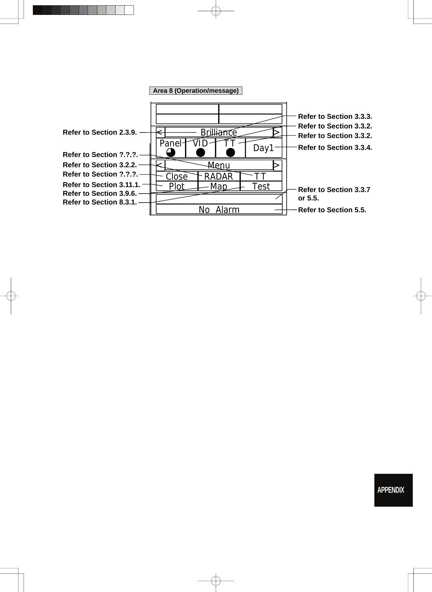
![8─7 8.3.1 Test Menu The performance status of this radar equipment can be checked on the TEST Menu. Self Test [I] Self-diagnostic function Monitor Test [II] Monitor check Keyboard Test [III] Operation panel check MON Display [IV] Performance monitor Error Logging [V] Error log display System INFO [VI] System information display MAGI [VII] Indication of magnetron current * Execution of MON Display requires a performance monitor unit NJU-85. Procedure 1 Press [RADAR MENU] key twice. Press [8] key. Press [9] key. The TEST Menu will appear. * Software button ⑥ located at the operation/message area in Section 2.3.9 is also available. 2 Select the check item you want to check, pressing the numeric keys [1] to [6] on Test Menu. The list of check items will appear. Exit 1 Press [RADAR MENU] key. The TEST Menu will be closed.](https://usermanual.wiki/Japan-Radio/NKE2062.Users-Manual-4/User-Guide-1377755-Page-59.png)
![8.3 PERFORMANCE CHECK 8─8 8yyyyyyyy8.3.1.1 Self-diagnosis function Check of Memory, Scanner Unit, and Communications Lines Memory Test 1) Memory check Sensor Test 2) Antenna check Line Test 3) Communication line check Procedure 1 Press [1] key while the Test Menu is open. The SELF TEST Menu will appear. 2 Select the item you want to check, pressing numeric keys [1] to [3] . The SELF CHECK Menu will appear. Exit 1 Press [RADAR MENU] key. The Self Test Menu will be closed. [I] Memory Test Checks for the performance of built-in memory. SDRAM SDRAM check SRAM SRAM check FLASH ROM Flash ROM check GRAPHIC Graphic check Procedure 1 Press [1] key while the Self Test menu is open. The Memory Test Menu will appear. 2 Select the item you want to check, pressing numeric keys [1] to [4]. When no abnormality is found, OK is displayed. When an abnormality is found, NG is displayed. Exit 1 Press [RADAR MENU] key. The menu will be closed.](https://usermanual.wiki/Japan-Radio/NKE2062.Users-Manual-4/User-Guide-1377755-Page-60.png)
![8─9 [II] Sensor Test Checks for signals from the antenna. Safety Switch Antenna’s safety switch check AZI Pulse Antenna rotation signal check HL Pulse Heading line signal check MH Current Check on the load current of high voltage in the modulator Trigger Radar trigger signal check Video Radar video check Procedure 1 Press [2] key while the Self Test menu is open. The Sensor Test menu will appear. When no abnormality is found, OK is displayed. When an abnormality is found, NG is displayed. In standby, ** will appear. Exit 1 Press [RADAR MENU] key. The menu will be closed. [III] Check of Communication Lines (Line Test) Check communication with operational devices and external navigators. MTR Check on connection with the transmitter-receiver NSK Check on connection with the NSK unit GPS Compass Check on connection with the GPS compass COM1 Check on connection with COM1 COM2 Check on connection with COM2 COM3 Check on connection with COM3 COM4 Check on connection with COM4 Plotter Key Check on connection with Plotter Key. Procedure 1 Press [3] key with the Self Test menu open. The Line Test menu will appear. When no abnormality is found, OK is displayed. When an abnormality is found, NG is displayed. The status display field of equipment not connected is **. Exit 1 Press [RADAR MENU] key. The menu will be closed.](https://usermanual.wiki/Japan-Radio/NKE2062.Users-Manual-4/User-Guide-1377755-Page-61.png)
![8.3 PERFORMANCE CHECK 8─10 8yyyyyyyy8.3.1.2 Monitor Test Checks for the display. The test pattern will be shown on the display. Procedure 1 Press [2] key while the Test Menu is open. The Monitor Test Menu will appear. 2 Select the item number you want to display, pressing numeric keys [1] to [5] of the test pattern. The selected test pattern will be displayed. Pattern 1: All colors are filled with white. Pattern 2: A white box is displayed on the black background of 1024 × 768 dots. Pattern 3: Displays rectangle × 2, circle × 2, and cross-shape× 13 (white lines on the black background). Pattern 4: Displays “H” of 9 dots × 9 dots on the entire screen (white character on the black background). Pattern 5: Gray scale display (16 levels) Pattern 6: Displays a color bar. Pattern 7: The square figure of a specified RGB value is shown at the center of the display. 3 To return to the original display, press any key. If Pattern7 is selected, resetting is performed by pressing the CLR button. If errors occur in the monitor, no test pattern will appear. Exit 1 Press [RADAR MENU] key. The menu will be closed.](https://usermanual.wiki/Japan-Radio/NKE2062.Users-Manual-4/User-Guide-1377755-Page-62.png)
![8─11 8.3.1.3 Operation Panel Test Checks for the controls and switches of the operation panel. Key Test 1) Key check Buzzer Test 2) Buzzer check Light 3) Keyboard light check Procedure 1 Press [3] key while the Test Menu is open. The Keyboard Test Menu will appear. 2 Select the item number you want to check, pressing numeric keys [1] to [3] of the item. The check contents will be displayed. Exit 1 Press [RADAR MENU] key. The menu will be closed. [I] Key Check Checks for the controls and switches of the operation panel. Procedure 1 Press [1] key while the Keyboard Test menu is open. The operation panel image will appear at the upper left of the display. Each key on the operation panel on the display is shown in reverse video at the same time the key is pressed, and the name of the pressed key is displayed. 2 To perform resetting, position the cursor to "EXIT" shown on the left side of the display, and press the [ENT] key or [0] key. Exit 1 Press [0] key. The menu will be closed.](https://usermanual.wiki/Japan-Radio/NKE2062.Users-Manual-4/User-Guide-1377755-Page-63.png)
![8.3 PERFORMANCE CHECK 8─12 8yyyyyyyy[II] Buzzer Test Checks for the operation panel buzzer. Procedure 1 Press [2] key while the Keyboard Test menu is open. The buzzer will sound. 2 The buzzer automatically stops after it sounds for a specified length of time. Exit 1 Press [RADAR MENU] key. The menu will be closed. [III] Light Checks for the operation panel light. Procedure 1 Press [3] key while the Keyboard Test menu is open. The brightness of the operation panel is gradually intensified at four levels. Exit 1 Press [RADAR MENU] key. The menu will be closed.](https://usermanual.wiki/Japan-Radio/NKE2062.Users-Manual-4/User-Guide-1377755-Page-64.png)
![8─13 8.3.1.4 MON Display The performance monitor status is shown. * A performance monitor unit is required. Transmitter System Check attenuation in the transmitter system Attenuation Value Receiver System Check attenuation in the receiver system MON Pattern Range Attenuation Value Procedure 1 Press [4] key while Test Menu is open. MON Display menu opens. 2 Turn [VRM] control to slide the VRM to the end of the performance monitor pattern. Attenuation in the receiver system is displayed in Attenuation Value of Receiver System. 3 Check the attenuation value. * Transmitter System Attenuation Value Normal operating range : -7.0dB<indication value<+2.0dB * Receiver System Attenuation Value Normal operating range : -3.0dB<indication value<+3.5dB Note: If Receiver System Attenuation Value display is under -3 dB or Transmitter System Attenuation Value display is under -7 dB with the the performance monitor test, radar should be checked by service engineer. This means that the TX/RX unit may be faulty. Consult with the near-by dealer or our sales department. Exit 1 Press [RADAR MENU] key. The menu will be closed.](https://usermanual.wiki/Japan-Radio/NKE2062.Users-Manual-4/User-Guide-1377755-Page-65.png)
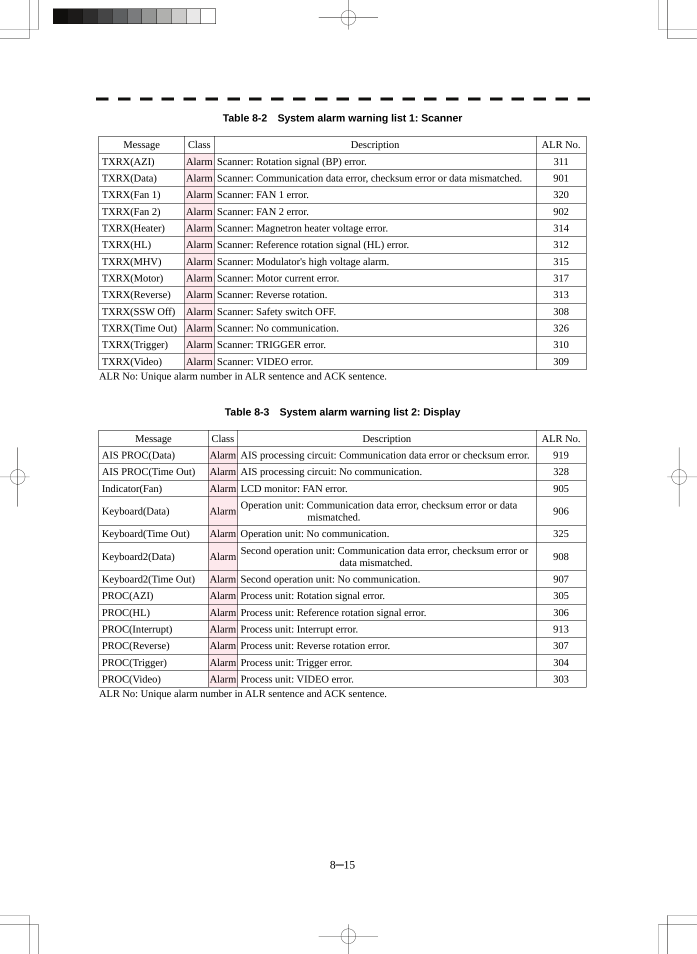
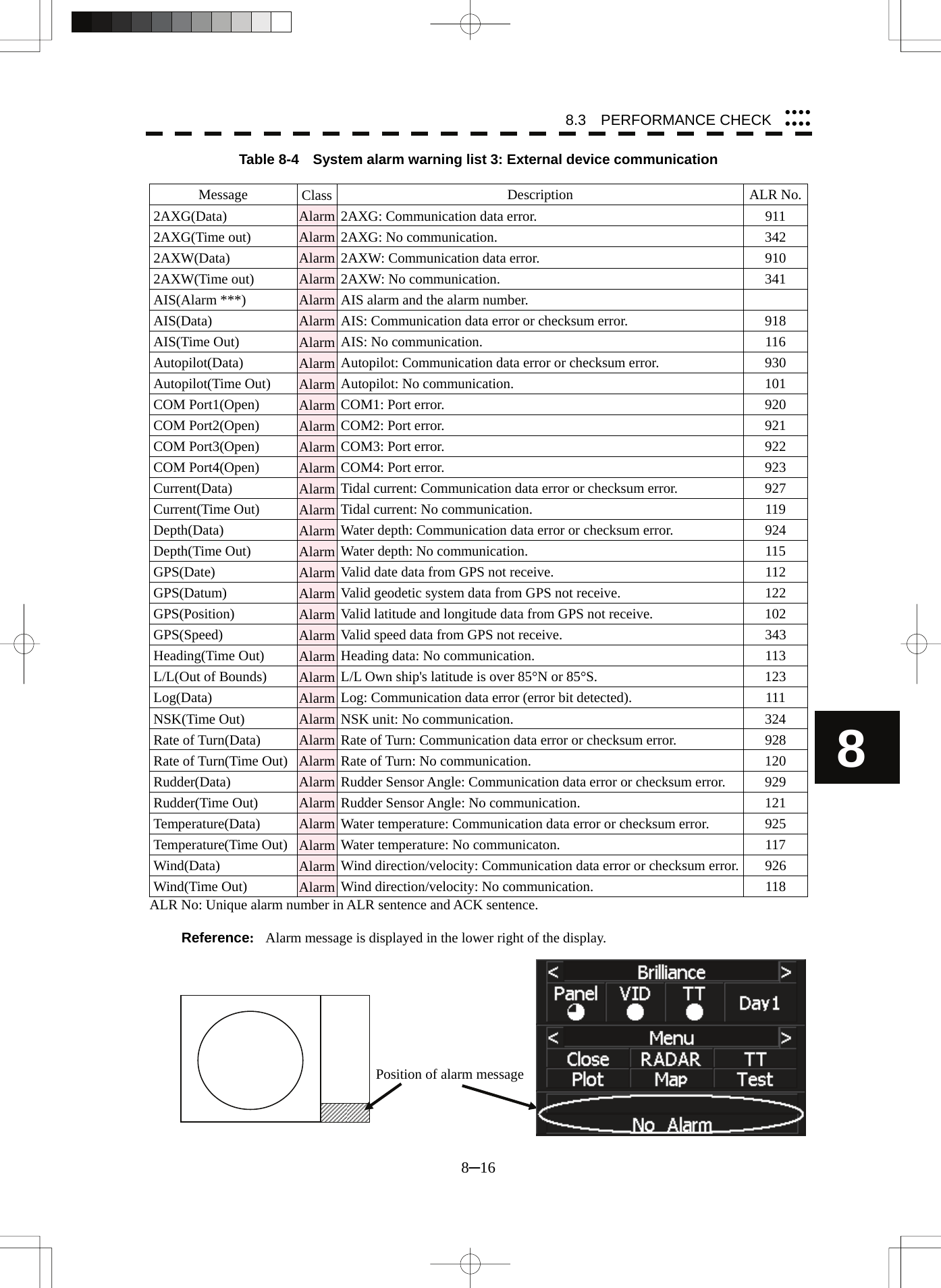
![8.3 PERFORMANCE CHECK 8─14 8yyyyyyyy8.3.1.5 Alarm Logging Displays previously occurred system errors with the dates and times when they occurred. The current error is displayed in reverse video. Procedure 1 Press [5] key while the Test Menu is open. The Alarm Log will appear. 2 Error logs will be displayed. For the display contents, refer to Table 8-2, Table 8-3 and Table 8-4. Press [1] key to switch the error log display modes between chronological display and reverse chronological display. Press [2] key to switch between error log display and alarm list display. Press [3] key to delete all error logs. Press [4] key to see the next page. Place the cursor over the listed error to see when it occurred. Exit 1 Press [RADAR MENU] key. The menu will be closed.](https://usermanual.wiki/Japan-Radio/NKE2062.Users-Manual-4/User-Guide-1377755-Page-66.png)
![8─17 8.3.1.6 System INFO Displays the current system information. Indicator Processor software version information TXRX Scanner software version information System No. System number TXRX Time Total Total operating time of the scanner unit (Total power-on time of the antenna unit) Motor Total operating time (Total power-on time) Transmit Total transmitting time (Total time during which radar was transmitted) System Time Total Total operating time of the display unit (Total power-on time of the display unit) Procedure 1 Press [6] key while the Test Menu is open. The System INFO Menu will appear. Exit 1 Press [RADAR MENU] key. The menu will be closed.](https://usermanual.wiki/Japan-Radio/NKE2062.Users-Manual-4/User-Guide-1377755-Page-69.png)
![8.3 PERFORMANCE CHECK 8─18 8yyyyyyyy8.3.1.7 MAGI Displays the MAGI bar indicating the magnetron current to check. Procedure 1 Check if the MAGI bar in the Test Menu reads the value below in a range of 24 NM. 6 kW: 4 to 5 scale marks 10 kW: 4 to 7 scale marks 25 kW: 6 to 9 scale marks Exit 1 Press [RADAR MENU] key. The menu will be closed.](https://usermanual.wiki/Japan-Radio/NKE2062.Users-Manual-4/User-Guide-1377755-Page-70.png)
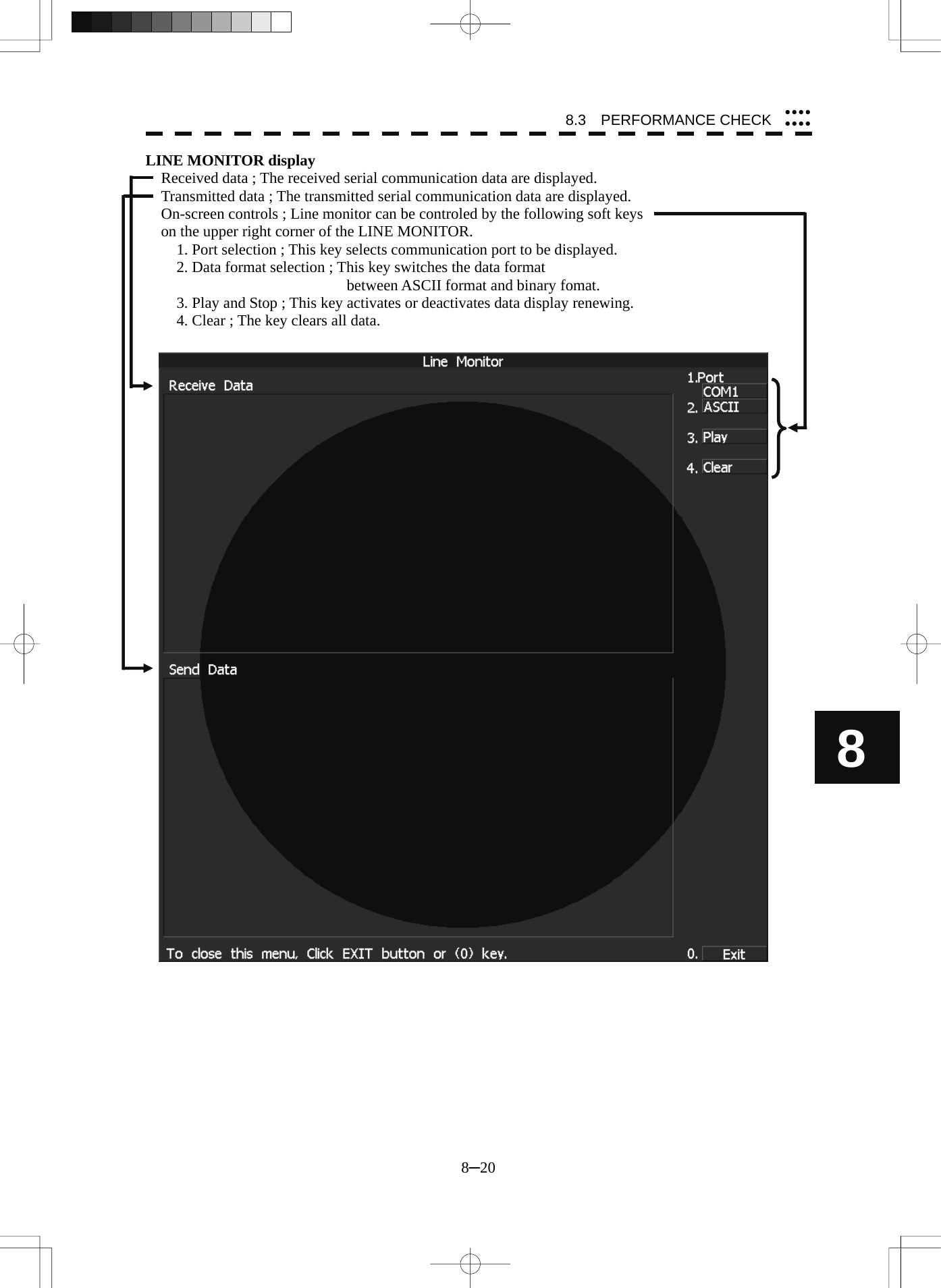
![8─19 8.3.2 Line Monitor Serial communication data can be seen on the built-in Line monitor. Line monitor can be used to make sure that the serial data are received properly. Procedure 1 Hold down [RADAR MENU] key. The Code Input Menu will appear. 2 Press [0] key. 3 Move the cursor onto the “ENT” button in the Code Input menu, and press [ENT] key. The Adjust Menu will appear. 4 Press [5] key. The COM Port Setting Menu will appear. 5 Press [7] key. The LINE MONITOR menu will appear. 6 Select the Communication port you want to see, pressing the numeric keys [1] to [8]. The LINE MONITOR appears. Refer to the next page for the display. Each ports on the menu repesets followingconnectors. COM1(GPS) J3 GPS COM2(PC) J8 NMEA COM3(NAV1) J6 AIS/NMEA COM4(NAV2) J9 AUX (Option) COM5(NSK/COMPASS) J5 GYRO / COMPASS COM6(TXRX) J2 SCANNER COM7(KEY BOARD1) J4 KEY BOARD COM8(KEY BOARD2) J9 AUX (Optioon) Exit 1 Press [0] key. 2 Press [RADAR MENU] key. The Main Menu will reappear.](https://usermanual.wiki/Japan-Radio/NKE2062.Users-Manual-4/User-Guide-1377755-Page-71.png)
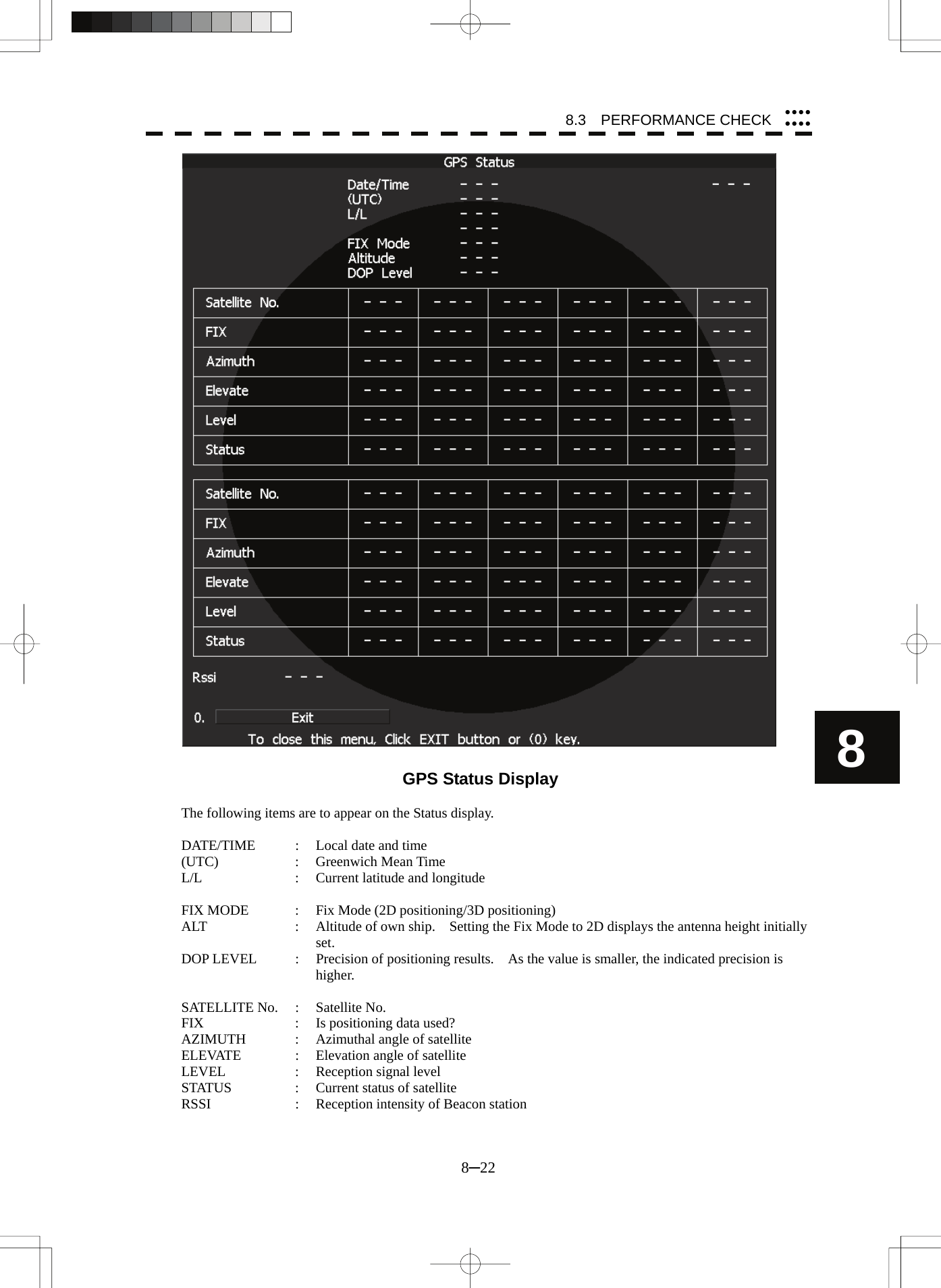
![8─21 8.3.3 GPS Reception Status Display (GPS Status) Display the reception status of the GPS receiver (GPS, DGPS and WAAS receivers) currently connected. Seize the status of satellites that are currently performing positioning. Procedure 1 Press [RADAR MENU] key. The Main Menu will appear. 2 Press [7] key. NAV Equipment Setting Menu will appear. 3 Press [7] key. GPS Setting Menu will appear. 4 Press [4] key. GPS Status Menu will appear. <The alternative procedure for steps above> 1 Hold down [RADAR MENU] key. The Code Input Menu will appear. 2 Press [0] key. 3 Move the cursor onto the “ENT” button in the Code Input menu, and press [ENT] key. The Adjust Menu will appear. 4 Press [6] key. NAV Equipment Setting menu opens. 5 Perform steps 3 and 4 in the “Procedure” above. Exit 1 Press [0] key. The Status Menu will be closed. 2 Press [RADAR MENU] key. The menu will be closed.](https://usermanual.wiki/Japan-Radio/NKE2062.Users-Manual-4/User-Guide-1377755-Page-73.png)


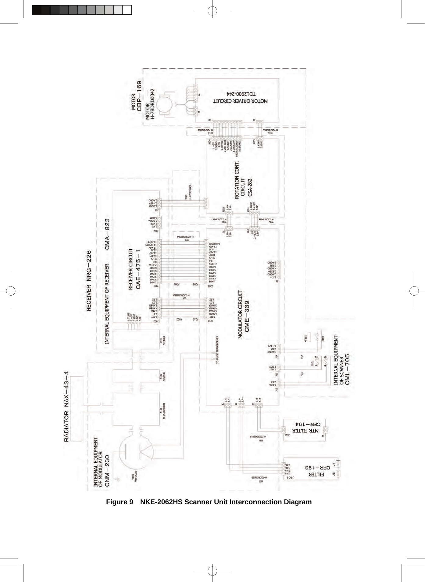
![9.2 TROUBLE SHOOTING 9─8 9 yyyyyyyyy9.2.2 Special Parts Table 9-8 Special Parts [I] JMA-5208/HS Parts No. Name Type Manufacturer Location Code V101 Magnetron MSF1422B NJRC Scanner 5VMAA00068A101 Circulator FCX68 Toshiba Scanner 6AJRD00001 A102 Diode Limiter NJS6930 NJRC Scanner 5EZAA00024 [II] JMA-5212-4/6/4HS/6HS Parts No. Name Type Manufacturer Location Code V101 Magnetron MAF1565N NJRC Scanner unit 5VHAA00102 A101/A102 Circulator FCX68R OrientMicrowave Scanner unit 5AJIX00027 A103 Dummy NJC4002 NJRC Scanner unit 5ANDF00001 A104 Filter NJC9952 NJRC Scanner unit 5AWAX00002A301 Diode Limiter NJS6930 NJRC Scanner unit 5ATBT00006 [III] JMA-5222-7/9 Parts No. Name Type Manufacturer Location Code V1 Magnetron M1568BS NJRC Scanner unit 5VMAA00106A101/A102 Circulator NJC3901M NJRC Scanner unit 5AJBV00007 A103 Dummy NJC4002 NJRC Scanner unit 5ANDF00001 A104 Filter NJC9952 NJRC Scanner unit 5AWAX00002A301 Diode Limiter NJS6930 NJRC Scanner unit 5ATBT00006 9.2.3 Circuit Block to be Repaired Table 9-9 Circuit Block to be Repaired (JMA-5208) Location Circuit Block Type Remarks Scanner Motor with gear CBP-153 DC brush motor (ordinary) Scanner Modulator CME-323 Excluding Magnetron Scanner Receiver NRG-226 Including CAE-475-1 Processor Radar processing circuit CDC-1350 Processor DSP circuit (TT) NCA-877A Processor Power supply terminal circuit unit NBD-866A Processor AIS processing circuit CDC-1353 Operation panel unit Operation circuit CCK-979 Operation panel unit PS2 connector circuit CQC-1204 Display Brilliance control circuit CCK-970 Brilliance controller NSK unit Gyro IF circuit CMJ-304E](https://usermanual.wiki/Japan-Radio/NKE2062.Users-Manual-4/User-Guide-1377755-Page-106.png)


![11.2 JMA-5222-7/9 TYPE RADAR 11─4 yyyyyyyyyyy11 11.4 SCANNER (NKE-2062) (1) Dimensions Height 432mm×Swing Circle 1220mm (2) Mass Approx. 24kg (3) Polarization Horizontal Polarization (4) Directional Characteristic Horizontal Beam Width: 2° (-3dB width) Vertical Beam Width: 30° (-3dB width) Sidelobe Level: Below –23dB (within ±10°) Below –26dB (outside ±10°) (5) Revolution Approx. 27rpm (Normal) (6) Peak Power 6 kW (7) Transmitting Frequency 9410 ±30MHz (8) Transmitting Tube Magnetron [MSF1422B] (9) Pulse width/Repetition Frequency Short Middle Long 0.125NM 0.08μs/2250Hz 0.25NM 0.08μs/2250Hz 0.5NM 0.08μs/2250Hz 0.25μs/1700Hz 0.75NM 0.08μs/2250Hz 0.25μs/1700Hz 0.5μs/1200Hz 1.5NM 0.08μs/2250Hz 0.25μs/1700Hz 0.5μs/1200Hz 3NM 0.25μs/1700Hz 0.5μs/1200Hz 1.0μs/650Hz 6NM 0.25μs/1700Hz 0.5μs/1200Hz 1.0μs/650Hz 12NM 0.25μs/1700Hz 0.5μs/1200Hz 1.0μs/650Hz 24NM 1.0μs/650Hz 48NM 1.0μs/650Hz 96NM 1.0μs/650Hz (10) Duplexer Circulator + Diode Limiter (11) Mixer MIC Front End (12) Intermediate Frequency Amplifier Intermediate Frequency: 60MHz Band Width: 20MHz(0.08μs) 6MHz(0.25μs,0.5μs) 3MHz(0.8μs, 1μs) Gain: More than 90dB Amplifying Characteristics: Logarithmic Amplifier (13) Overall Noise Figure 6dB(Average)](https://usermanual.wiki/Japan-Radio/NKE2062.Users-Manual-4/User-Guide-1377755-Page-122.png)
![11─5 11.5 SCANNER (NKE-2062HS) (1) Dimensions Height 432mm×Swing Circle 1220mm (2) Mass Approx. 24kg (3) Polarization Horizontal Polarization (4) Directional Characteristic Horizontal Beam Width: 2° (-3dB width) Vertical Beam Width: 30° (-3dB width) Sidelobe Level: Below –23dB (within ±10°) Below –26dB (outside ±10°) (5) Revolution Approx. 48rpm (6) Peak Power 6 kW (7) Transmitting Frequency 9410 ±30MHz (8) Transmitting Tube Magnetron [MSF1422B] (9) Pulse width/Repetition Frequency Short Middle Long 0.125NM 0.08μs/2250Hz 0.25NM 0.08μs/2250Hz 0.5NM 0.08μs/2250Hz 0.25μs/1700Hz 0.75NM 0.08μs/2250Hz 0.25μs/1700Hz 0.5μs/1200Hz 1.5NM 0.08μs/2250Hz 0.25μs/1700Hz 0.5μs/1200Hz 3NM 0.25μs/1700Hz 0.5μs/1200Hz 1.0μs/650Hz 6NM 0.25μs/1700Hz 0.5μs/1200Hz 1.0μs/650Hz 12NM 0.25μs/1700Hz 0.5μs/1200Hz 1.0μs/650Hz 24NM 1.0μs/650Hz 48NM 1.0μs/650Hz 96NM 1.0μs/650Hz (10) Duplexer Circulator + Diode Limiter (11) Mixer MIC Front End (12) Intermediate Frequency Amplifier Intermediate Frequency: 60MHz Band Width: 20MHz(0.08μs) 6MHz(0.25μs,0.5μs) 3MHz(0.8μs, 1μs) Gain: More than 90dB Amplifying Characteristics: Logarithmic Amplifier (13) Overall Noise Figure 6dB(Average)](https://usermanual.wiki/Japan-Radio/NKE2062.Users-Manual-4/User-Guide-1377755-Page-123.png)
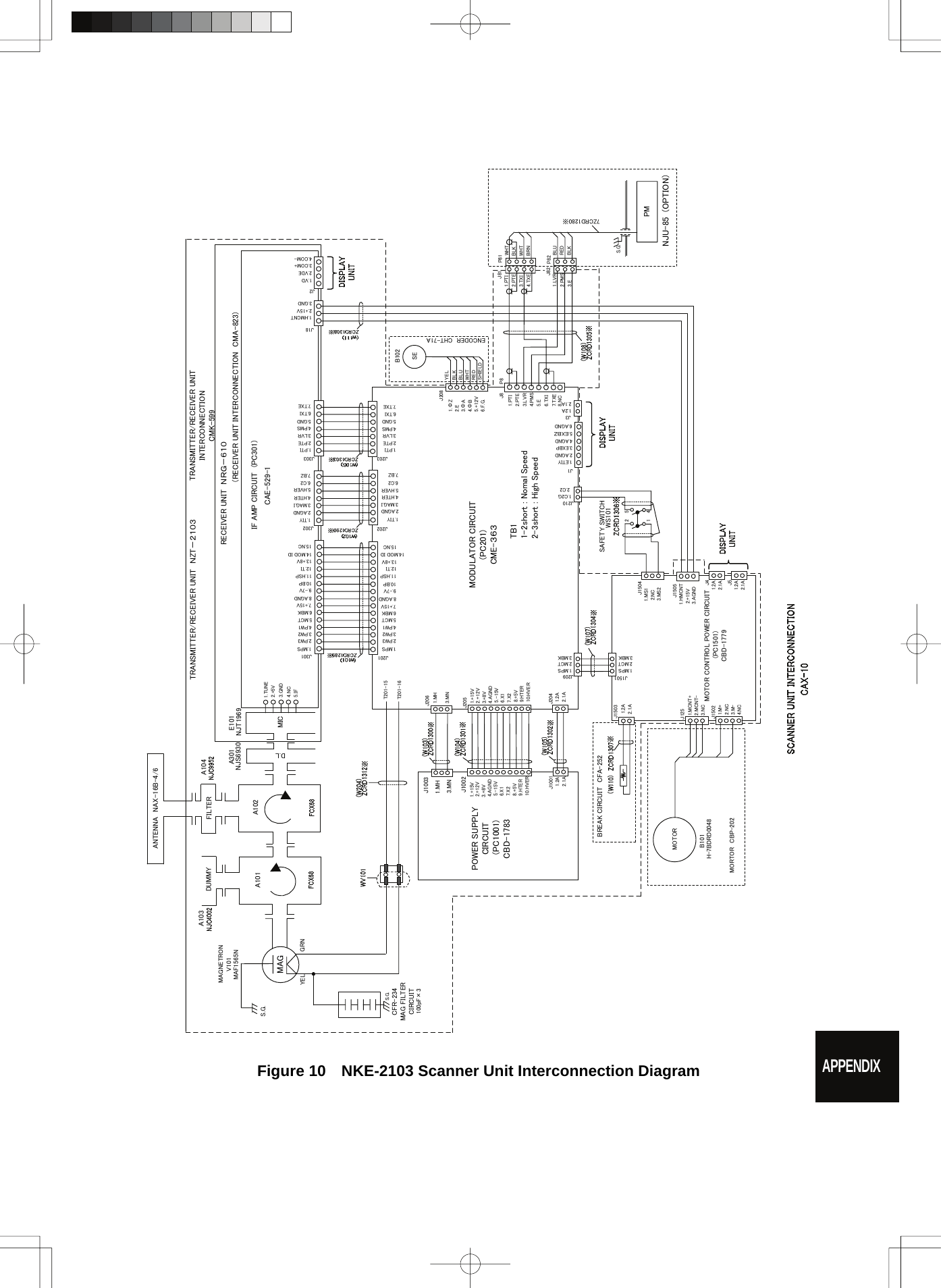
![11.2 JMA-5222-7/9 TYPE RADAR 11─6 11 yyyyyyyyyyy11.6 SCANNER (NKE-2103-4/6) (1) Dimensions 10kW-4ft: Height 458mm×Swing Circle 1285mm 10kW-6ft: Height 458mm×Swing Circle 1910mm (2) Mass 10kW-4ft: Approx. 38 kg 10kW-6ft: Approx. 40 kg (3) Polarization Horizontal Polarization (4) Directional Characteristic Horizontal Beam Width: 1.8° (4ft, –3dB width) 1.2° (6ft, –3dB width) Vertical Beam Width: 20° (4/6ft, –3dB width) Sidelobe Level: Below –26dB (4/6ft, within ±10°) Below –30dB (4/6ft, outside ±10°) (5) Revolution Approx. 27rpm (4/6ft, Normal) (6) Peak Power 10kW ±50% (7) Transmitting Frequency 9410 ±30MHz (8) Transmitting Tube Magnetron [MAF1565N] (9) Pulse width/Repetition Frequency SP1:0.08μs/2250Hz/Wide MP1:0.25μs/1700Hz/Middle、MP2:0.5μs/1200Hz/Middle LP1:0.8μs/750Hz/Narrow、LP2:1.0μs/650Hz/Narrow 0.125NM 0.08μs/2250Hz(SP1) 0.25NM 0.08μs/2250Hz(SP1) 0.5NM 0.08μs/2250Hz(SP1) 0.25μs/1700Hz(MP1) 0.75NM 0.08μs/2250Hz(SP1) 0.25μs/1700Hz(MP1) 0.5μs/1200Hz(MP2) 1.5NM 0.08μs/2250Hz(SP1) 0.25μs/1700Hz(MP1) 0.5μs/1200Hz(MP2) 3NM 0.25μs/1700Hz(MP1) 0.5μs/1200Hz(MP2) 0.8μs/750Hz(LP1) 6NM 0.5μs/1200Hz(MP2) 0.8μs/750Hz(LP1) 1.0μs/650Hz(LP2) 12NM 0.5μs/1200Hz(MP2) 0.8μs/750Hz(LP1) 1.0μs/650Hz(LP2) 24NM 1.0μs/650Hz(LP2) 48NM 1.0μs/650Hz(LP2) 96NM 1.0μs/650Hz(LP2) (10) Duplexer Circulator + Diode Limiter (11) Mixer MIC Front End (12) Intermediate Frequency Amplifier Intermediate Frequency: 60MHz Band Width: 20MHz(0.08μs) 8MHz(0.25μs,0.5μs) 3MHz(0.8μs, 1μs) Gain: More than 90dB Amplifying Characteristics: Logarithmic Amplifier (13) Overall Noise Figure 7.5dB (Average)](https://usermanual.wiki/Japan-Radio/NKE2062.Users-Manual-4/User-Guide-1377755-Page-124.png)
![11─7 11.7 SCANNER (NKE-2103-4HS/6HS) (1) Dimensions 10kW-4ft: Height 458mm×Swing Circle 1285mm 10kW-6ft: Height 458mm×Swing Circle 1910mm (2) Mass 10kW-4ft: Approx. 38 kg 10kW-6ft: Approx. 40 kg (3) Polarization Horizontal Polarization (4) Directional Characteristic Horizontal Beam Width: 1.8° (4ft, –3dB width) 1.2° (6ft, –3dB width) Vertical Beam Width: 20° (4/6ft, –3dB width) Sidelobe Level: Below –26dB (4/6ft, within ±10°) Below –30dB (4/6ft, outside ±10°) (5) Revolution Approx. 48rpm (4/6ft) (6) Peak Power 10kW ±50% (7) Transmitting Frequency 9410 ±30MHz (8) Transmitting Tube Magnetron [MAF1565N] (9) Pulse width/Repetition Frequency SP1:0.08μs/2250Hz/Wide MP1:0.25μs/1700Hz/Middle、MP2:0.5μs/1200Hz/Middle LP1:0.8μs/750Hz/Narrow、LP2:1.0μs/650Hz/Narrow 0.125NM 0.08μs/2250Hz(SP1) 0.25NM 0.08μs/2250Hz(SP1) 0.5NM 0.08μs/2250Hz(SP1) 0.25μs/1700Hz(MP1) 0.75NM 0.08μs/2250Hz(SP1) 0.25μs/1700Hz(MP1) 0.5μs/1200Hz(MP2) 1.5NM 0.08μs/2250Hz(SP1) 0.25μs/1700Hz(MP1) 0.5μs/1200Hz(MP2) 3NM 0.25μs/1700Hz(MP1) 0.5μs/1200Hz(MP2) 0.8μs/750Hz(LP1) 6NM 0.5μs/1200Hz(MP2) 0.8μs/750Hz(LP1) 1.0μs/650Hz(LP2) 12NM 0.5μs/1200Hz(MP2) 0.8μs/750Hz(LP1) 1.0μs/650Hz(LP2) 24NM 1.0μs/650Hz(LP2) 48NM 1.0μs/650Hz(LP2) 96NM 1.0μs/650Hz(LP2) (10) Duplexer Circulator + Diode Limiter (11) Mixer MIC Front End (12) Intermediate Frequency Amplifier Intermediate Frequency: 60MHz Band Width: 20MHz(0.08μs) 8MHz(0.25μs,0.5μs) 3MHz(0.8μs, 1μs) Gain: More than 90dB Amplifying Characteristics: Logarithmic Amplifier (13) Overall Noise Figure 7.5dB (Average)](https://usermanual.wiki/Japan-Radio/NKE2062.Users-Manual-4/User-Guide-1377755-Page-125.png)
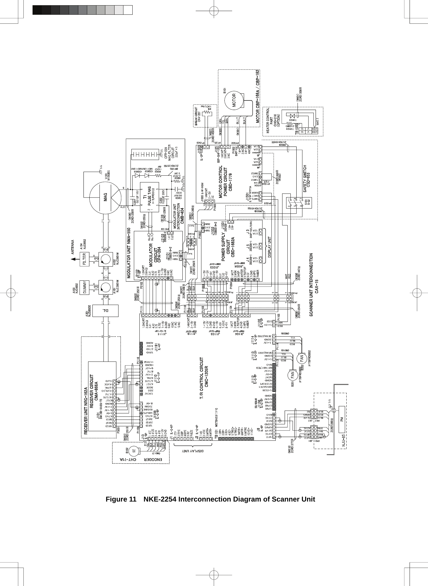
![11.4 SCANNER (NKE-2254-7/9) 11─8 yyyyyyyyyyy11 11.8 SCANNER (NKE-2254-7/9) (1) Dimensions 25kW-7ft: Height 536mm×Swing Circle 2270mm 25kW-9ft: Height 536mm×Swing Circle 2825mm (2) Mass 25kW-7ft: Approx. 58 kg 25kW-9ft: Approx. 60 kg (3) Polarization Horizontal Polarization (4) Directional Characteristics Horizontal Beam Width: 1.0° (7ft, –3dB width) 0.8° (9ft, –3dB width) Vertical Beam Width 20° (7/9ft, –3dB width) Sidelobe Level: Below –26dB (7/9ft, within ±10°) Below –30dB (7/9ft, outside ±10°) (5) Revolution 24rpm (7/9ft, Normal) (6) Peak Power 25kW ±50% (7) Transmitting Frequency 9410 ±30MHz (8) Transmitting Tube Magnetron [M1568BS] (9) Pulse Width/Repetition Frequency SP1:0.07μs/2250Hz/Wide MP1:0.2μs/2250Hz/Middle、MP2:0.4μs/1400Hz/Middle LP1:0.8μs/750Hz/Narrow、LP2:1.0μs/650Hz/Narrow、LP3:1.2μs/510Hz/Narrow 0.125NM 0.07μs/2250Hz(SP1) 0.25NM 0.07μs/2250Hz(SP1) 0.5NM 0.07μs/2250Hz(SP1) 0.2μs/2250Hz(MP1) 0.75NM 0.07μs/2250Hz(SP1) 0.2μs/2250Hz(MP1) 0.4μs/1400Hz(MP2) 1.5NM 0.07μs/2250Hz(SP1) 0.2μs/2250Hz(MP1) 0.4μs/1400Hz(MP2) 3NM 0.2μs/2250Hz(MP1) 0.4μs/1400Hz(MP2) 0.8μs/750Hz(LP1) 6NM 0.4μs/1400Hz(MP2) 0.8μs/750Hz(LP1) 1.0μs/650Hz(LP2) 12NM 0.4μs/1400Hz(MP2) 0.8μs/750Hz(LP1) 1.0μs/650Hz(LP2) 24NM 1.0μs/650Hz(LP2) 48NM 1.0μs/650Hz(LP2) 96NM 1.2μs/510Hz(LP3) (10) Duplexer Circulator + Diode Limiter (11) Mixer MIC Front End (12) Intermediate Frequency Amplifier Intermediate Frequency: 60MHz Band Width: 25MHz(0.07μs) 8MHz(0.2μs, 0.4μs) 3MHz(0.8μs, 1.0μS, 1.2μs) Gain: More than 90dB Amplifying Characteristics: Logarithmic Amplifier (13) Overall Noise Figure 7.5dB (Average)](https://usermanual.wiki/Japan-Radio/NKE2062.Users-Manual-4/User-Guide-1377755-Page-126.png)