K Best Technology 5117R E1 Spread Spectrum Radio User Manual 2
K-Best Technology Inc. E1 Spread Spectrum Radio 2
UserManual.wiki
>
K Best Technology
>
5117R User Manual
>
User Manual 2
Contents
1.
User Manual 1
2.
User Manual 2
User Manual 2
Navigation menu
Upload a User Manual
Namespaces
Wiki Guide
HTML
PDF
Info
Views
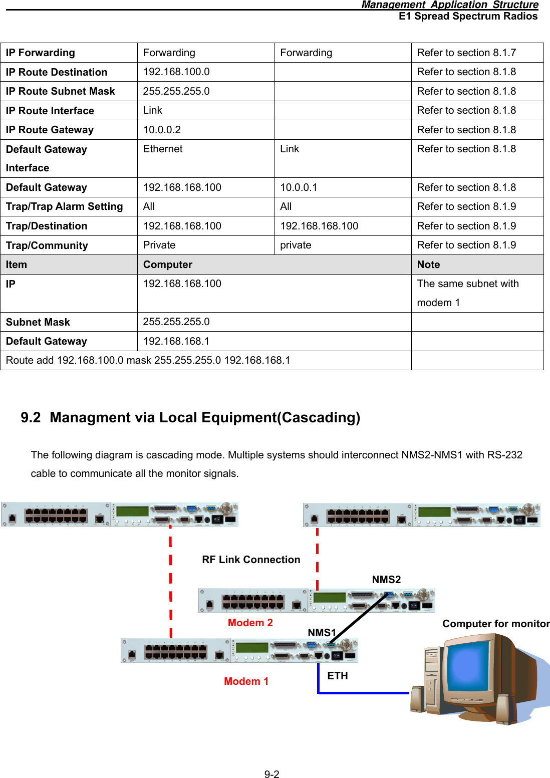
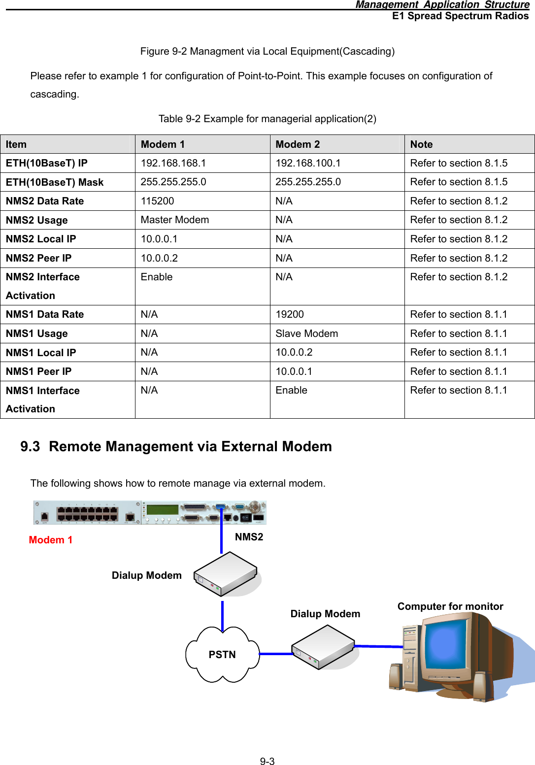
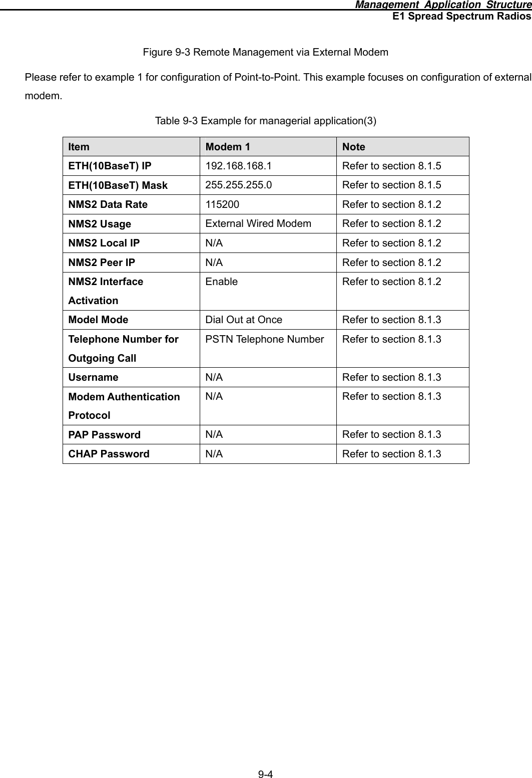
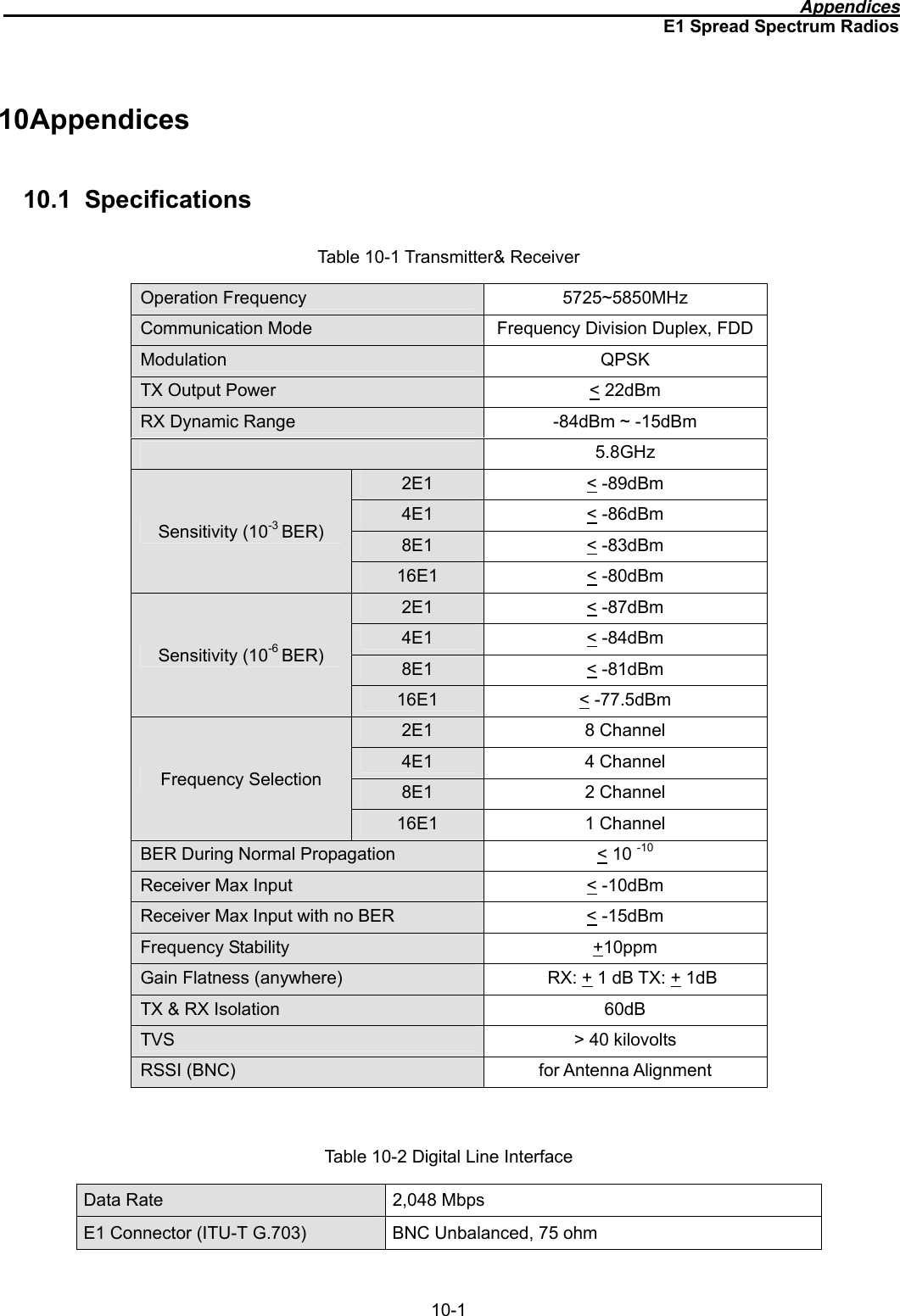
User Manual
Discussion / Help
Navigation
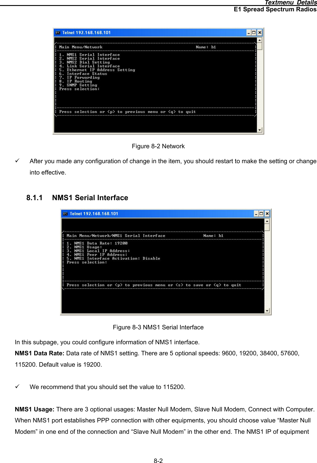
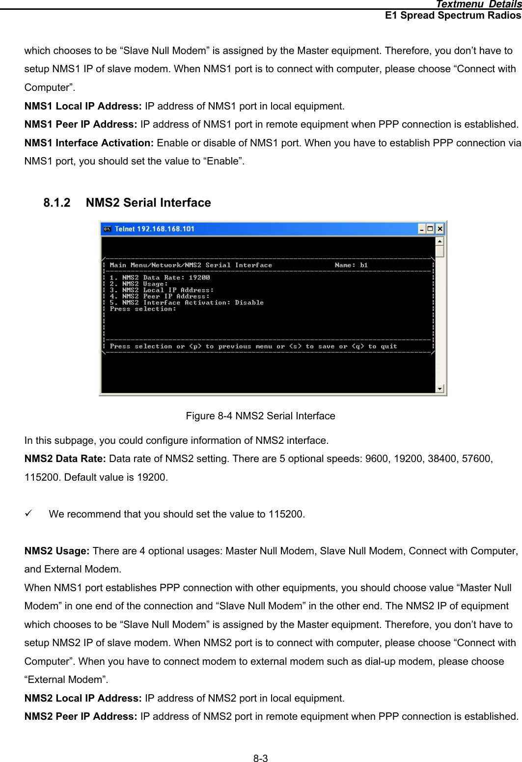
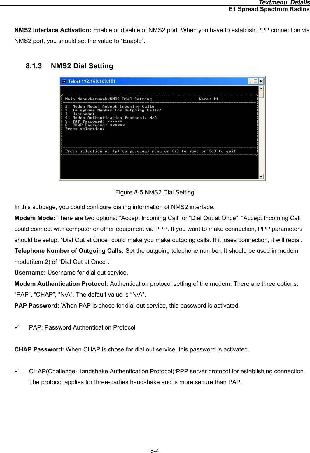
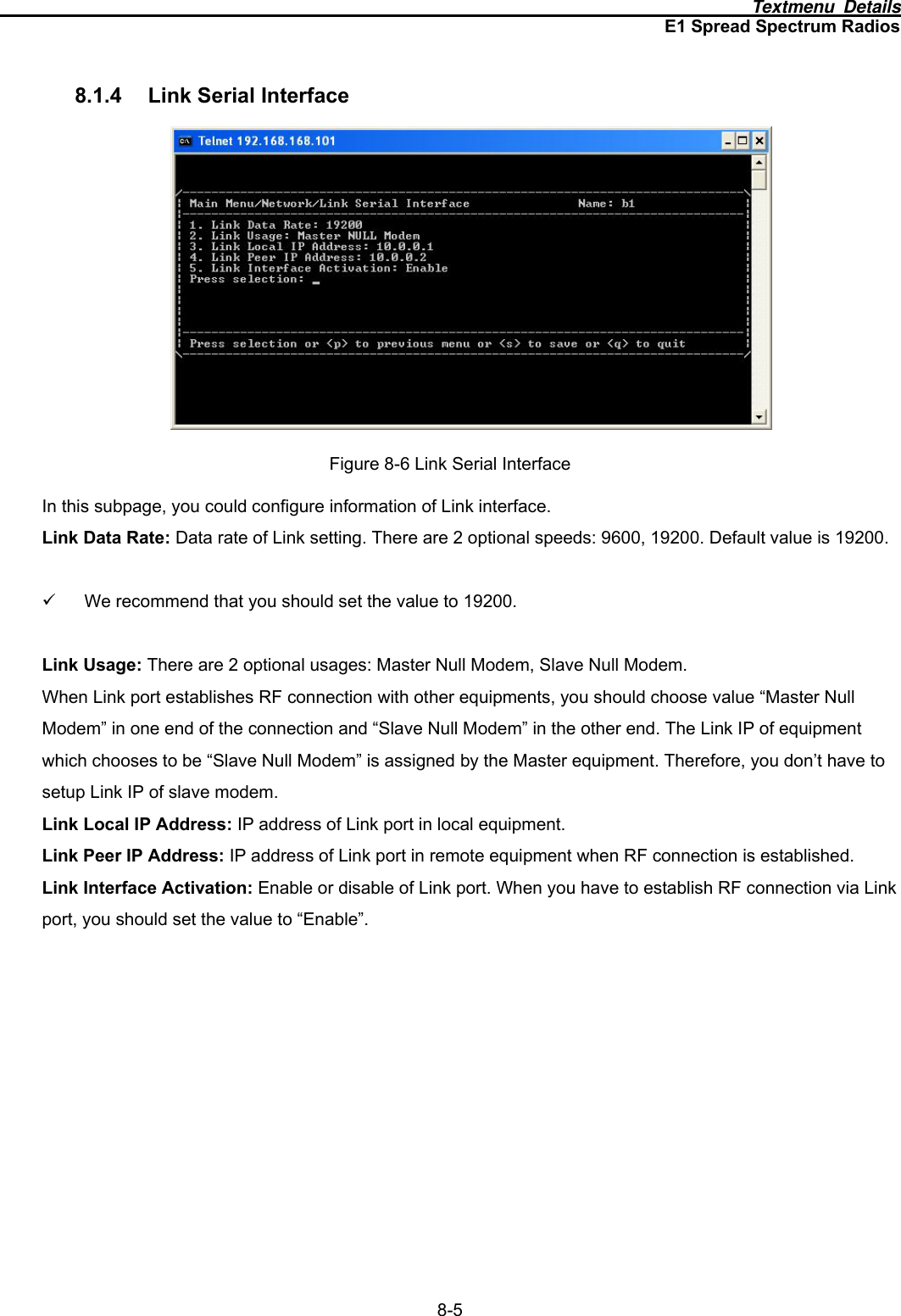
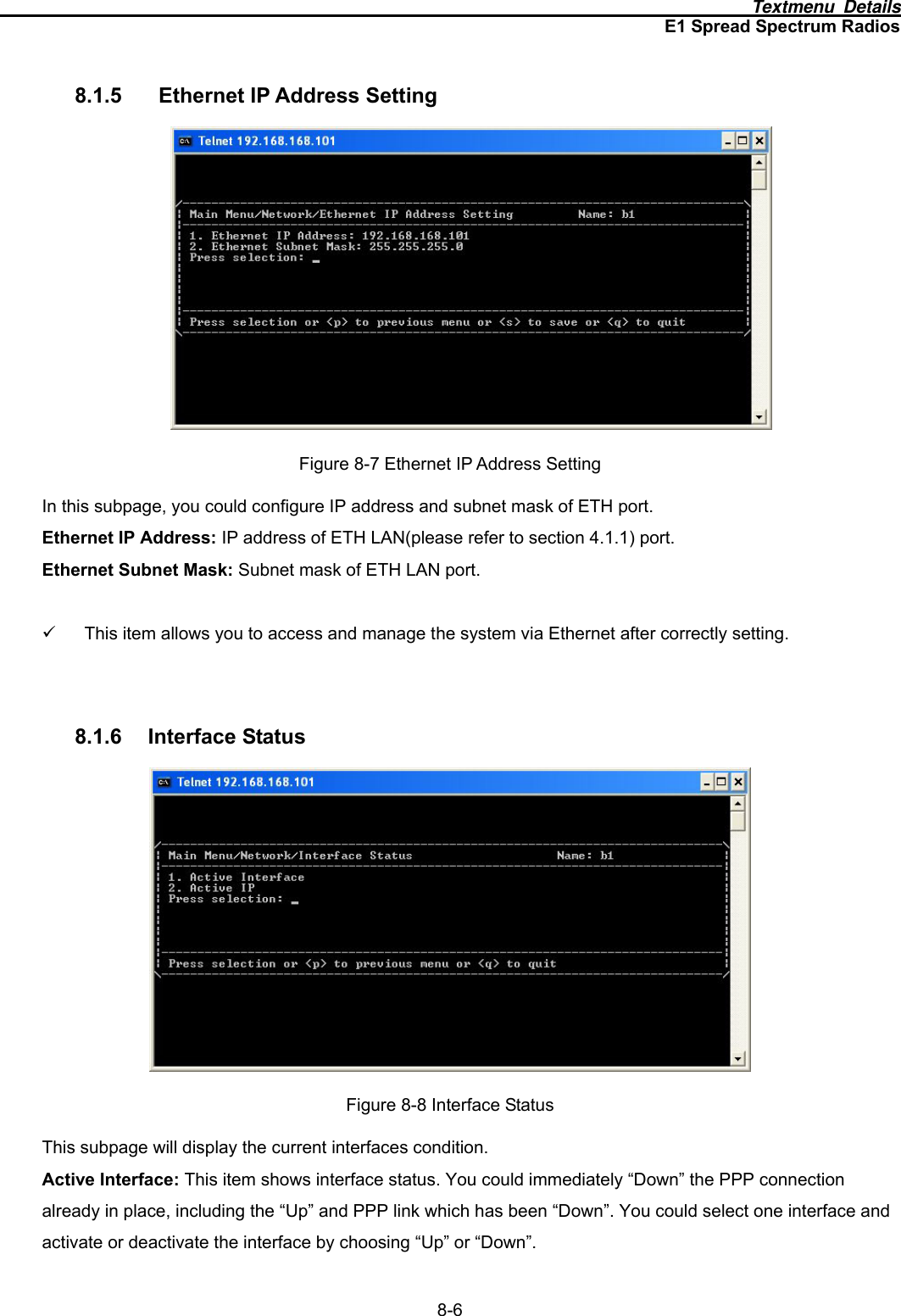
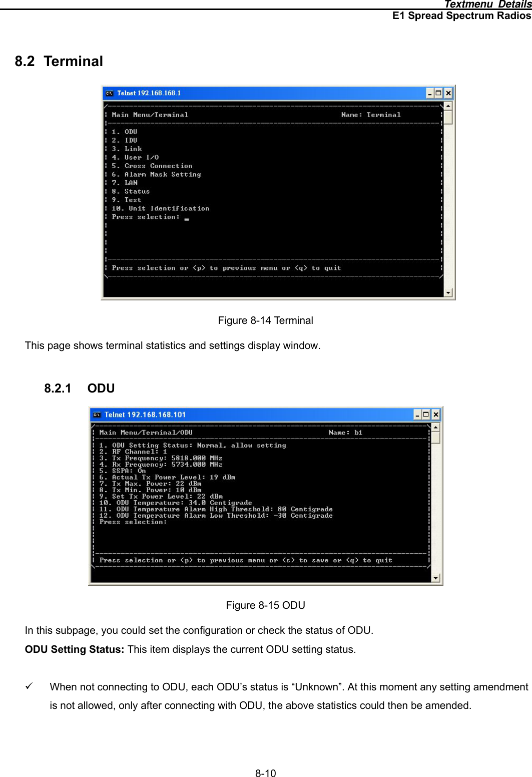
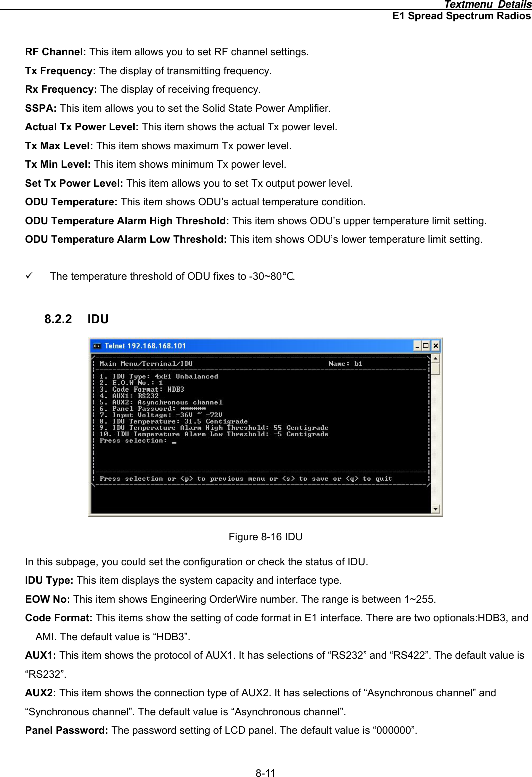
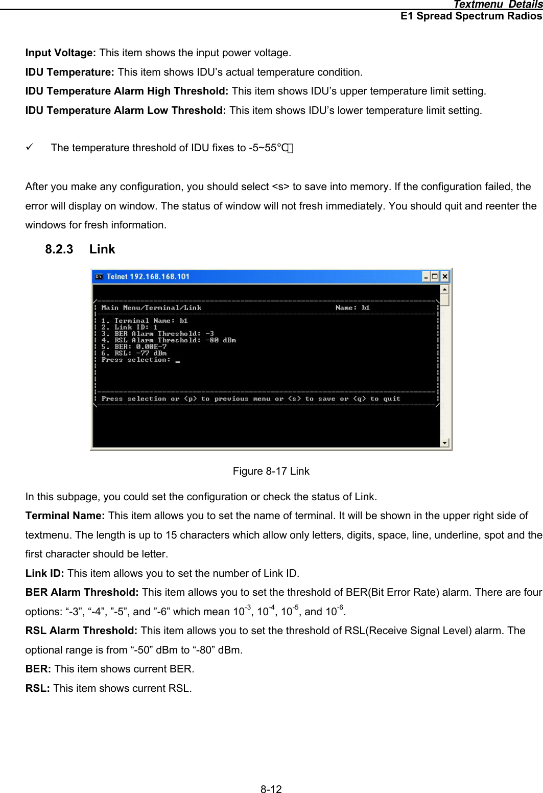
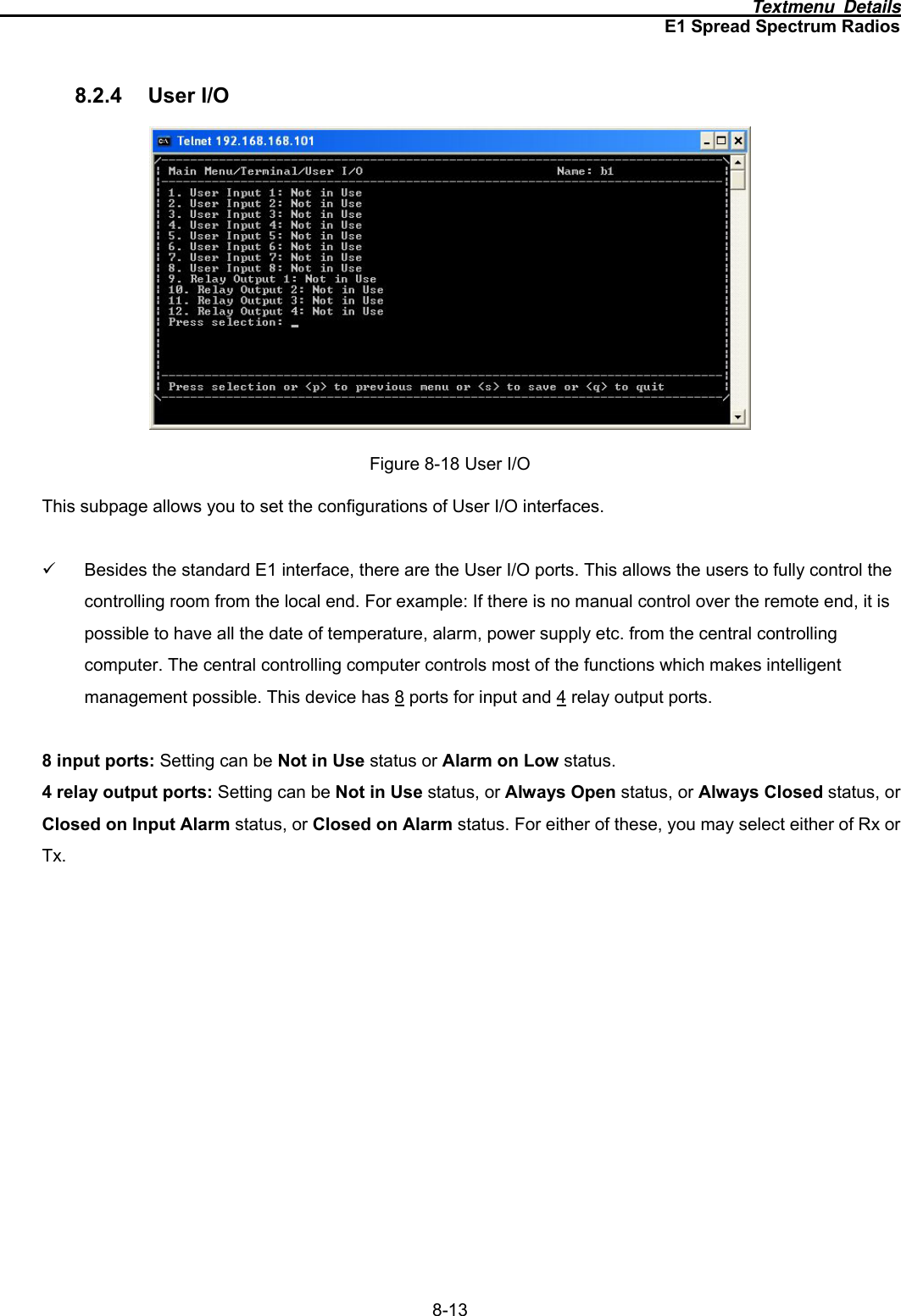
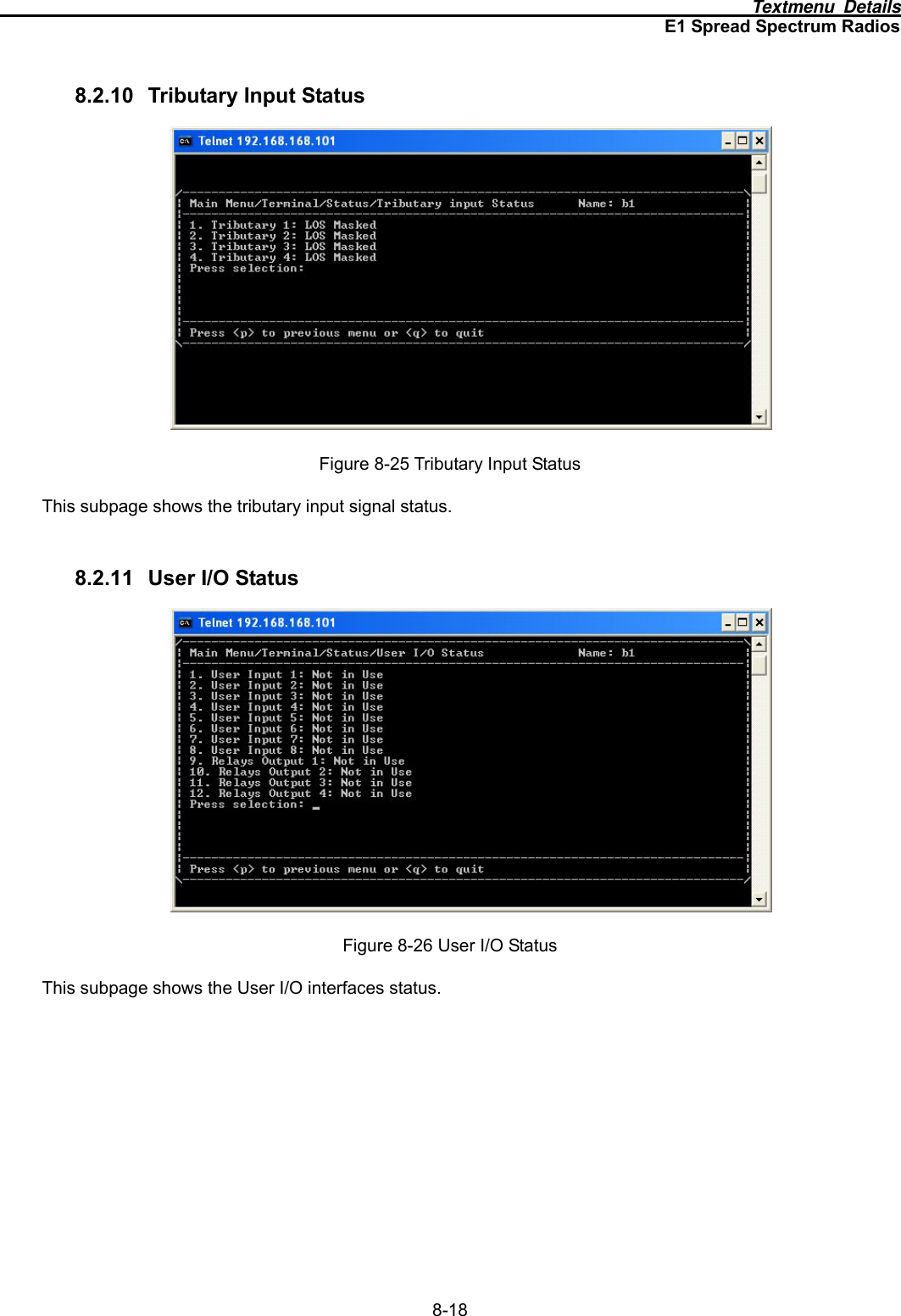
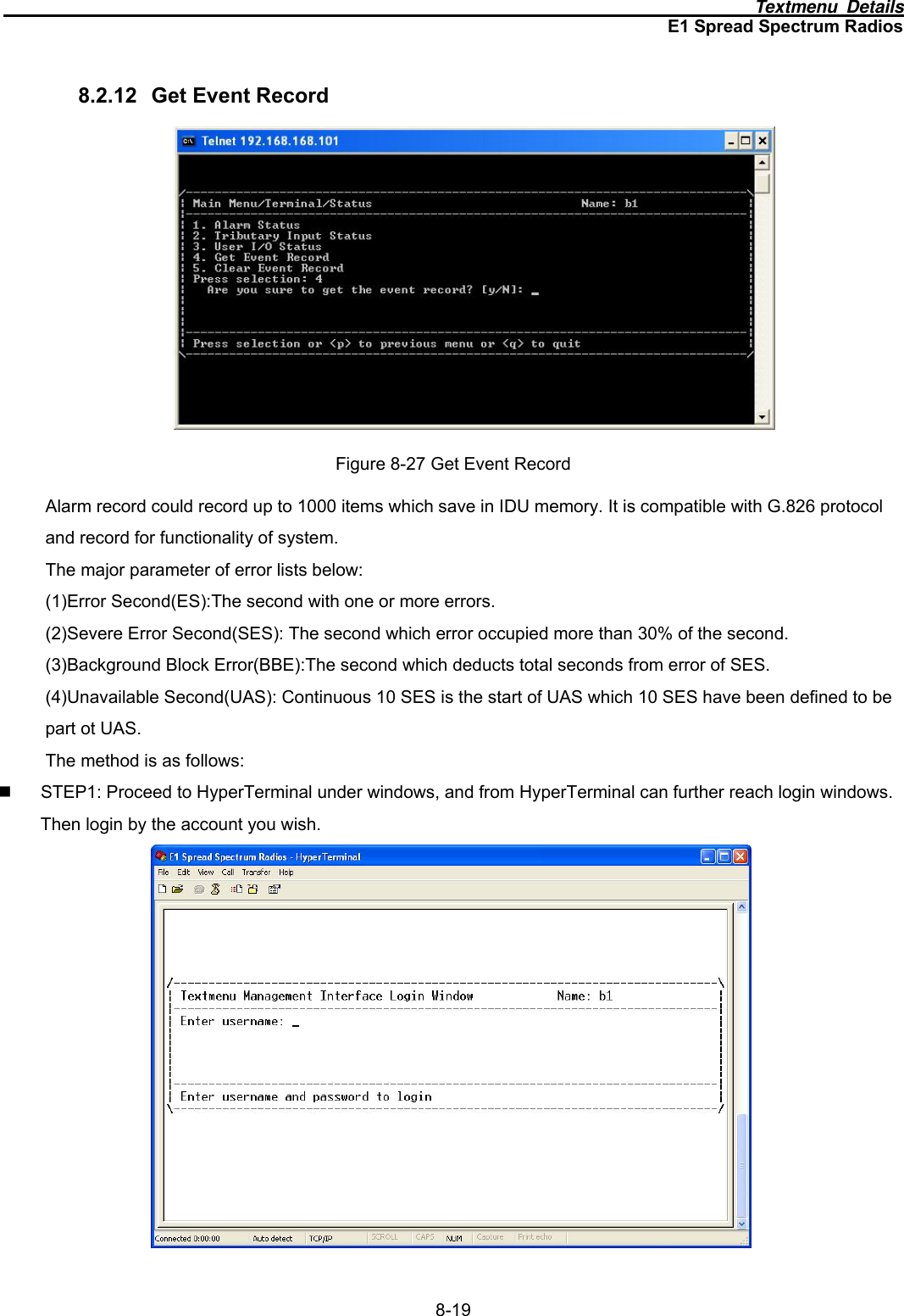
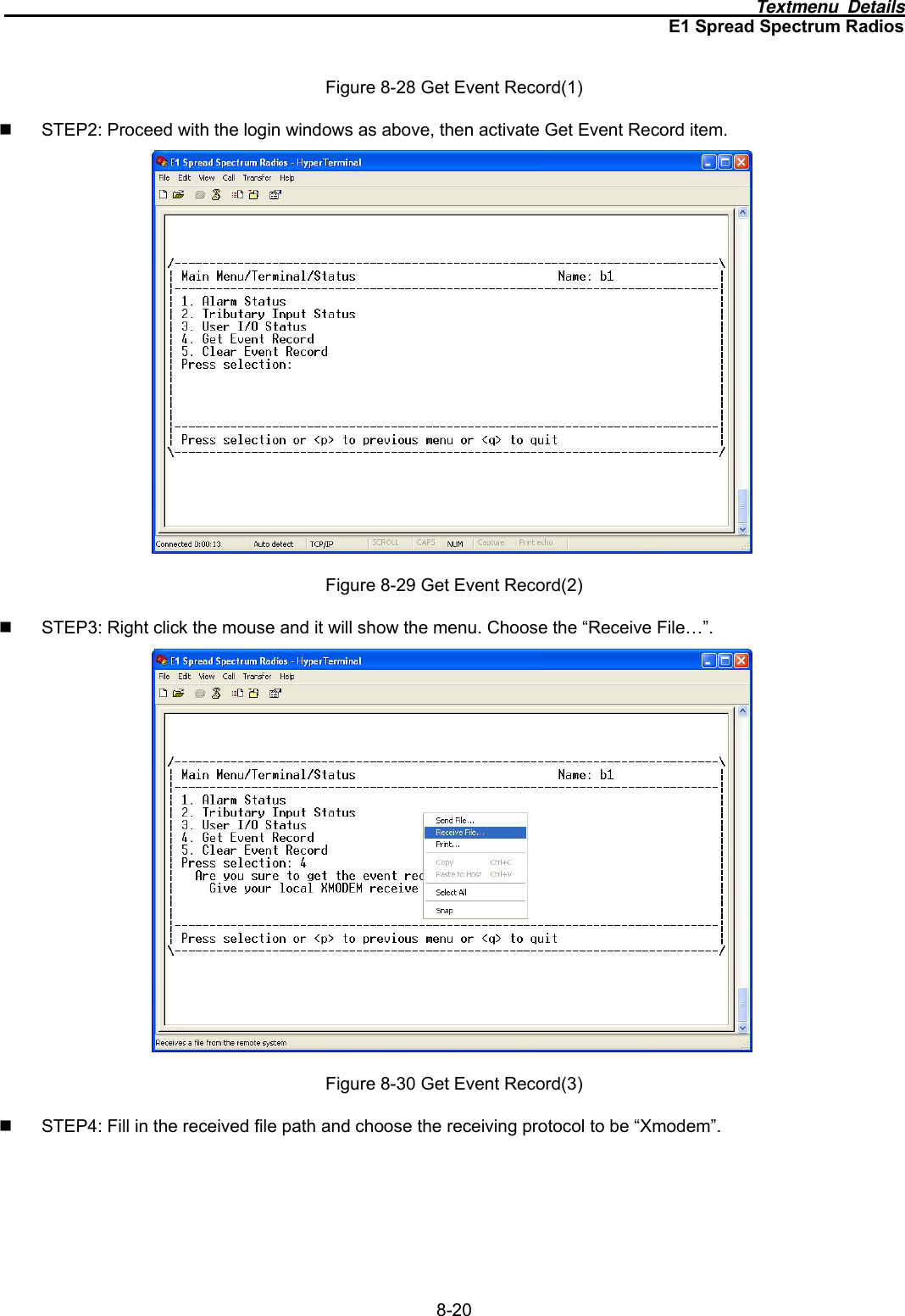
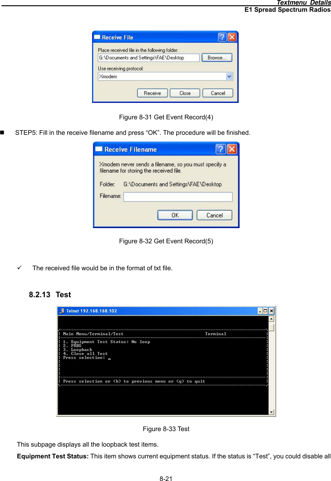
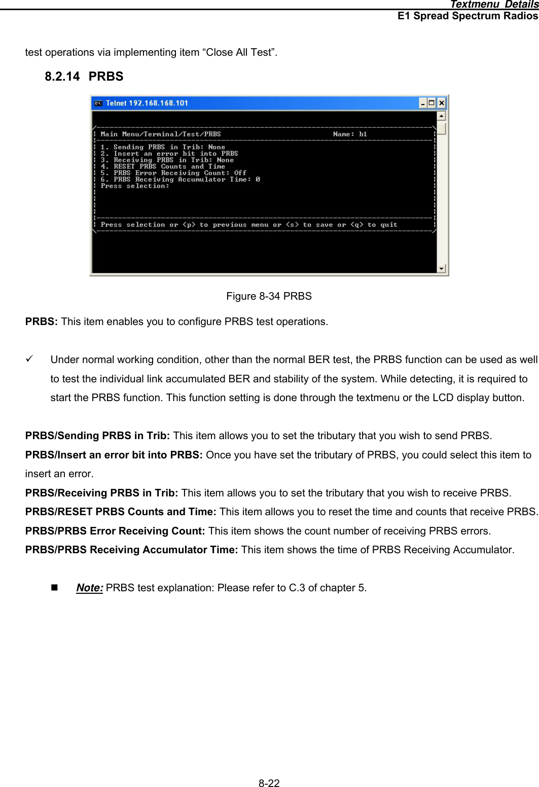
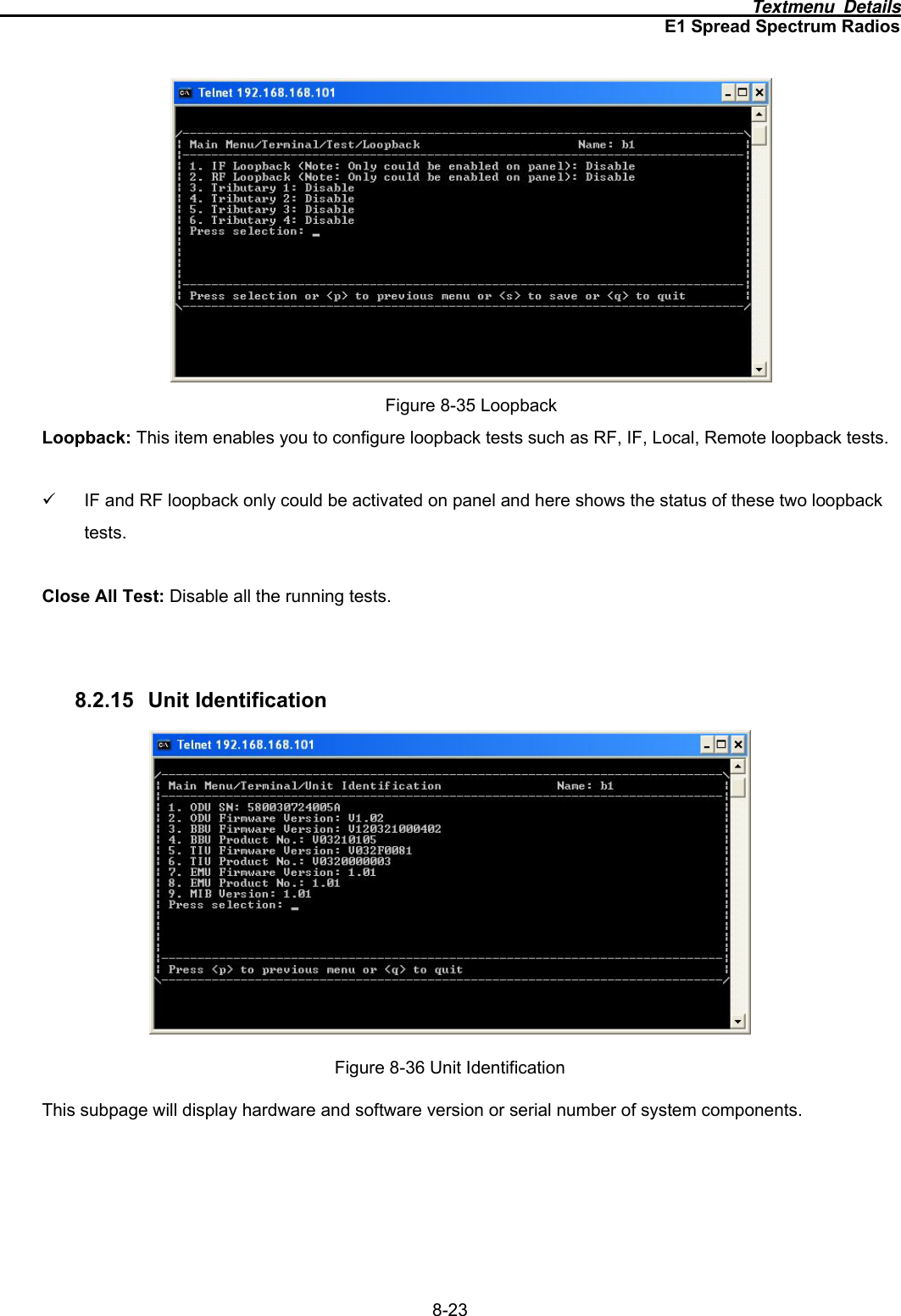
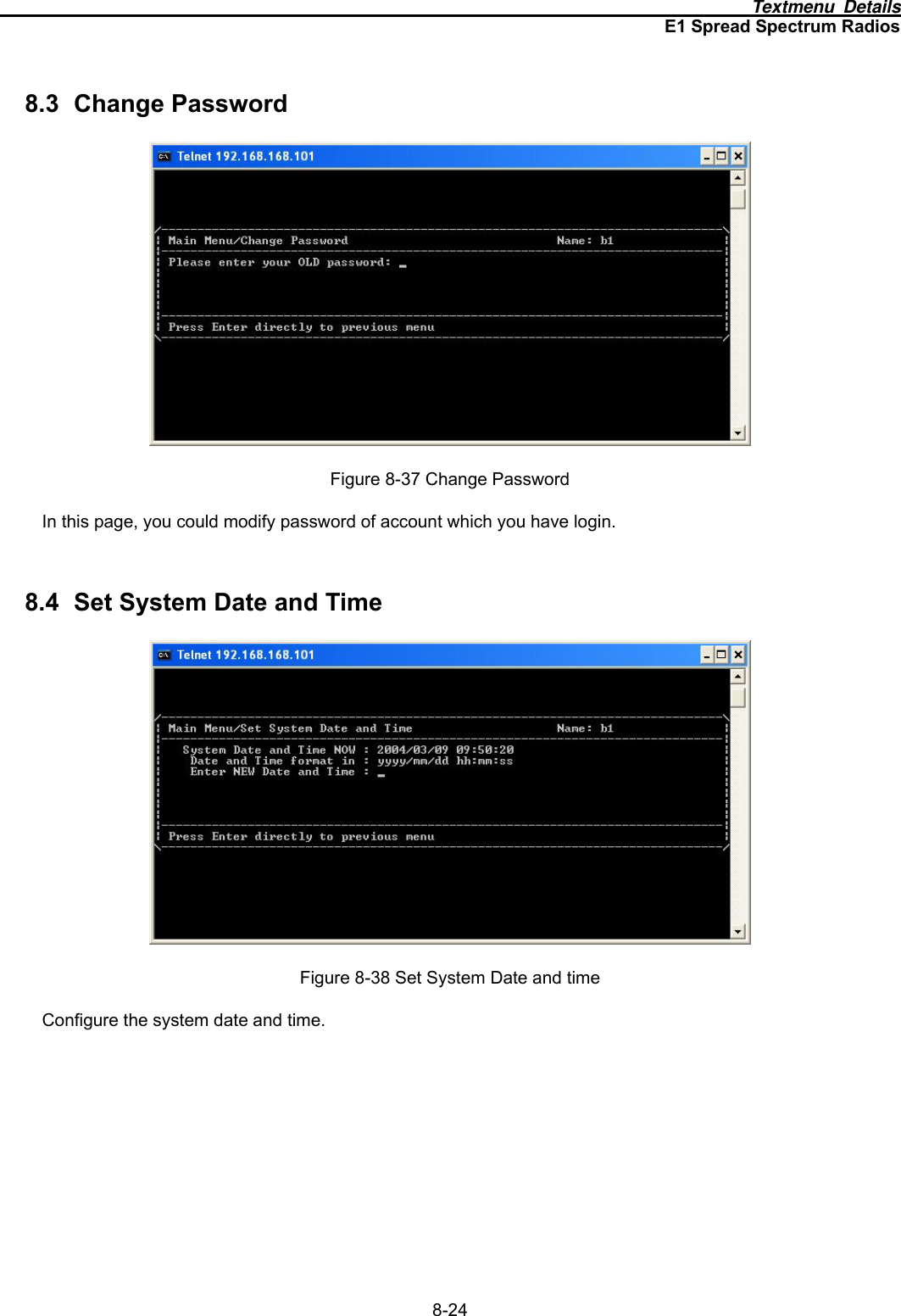
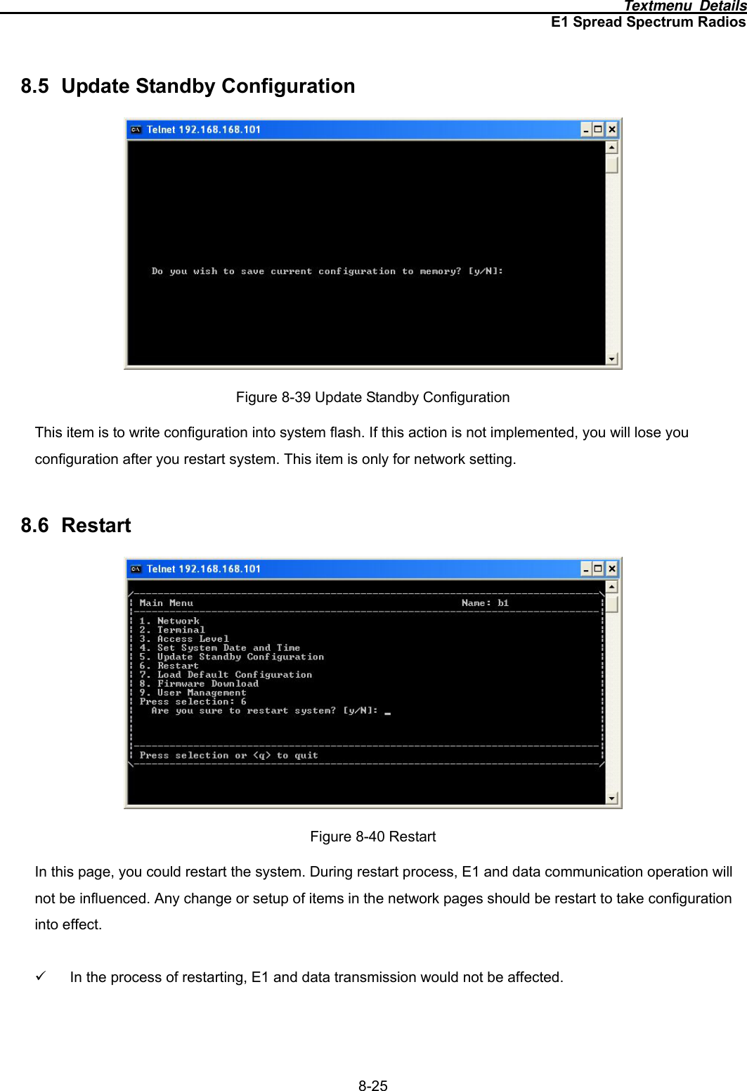
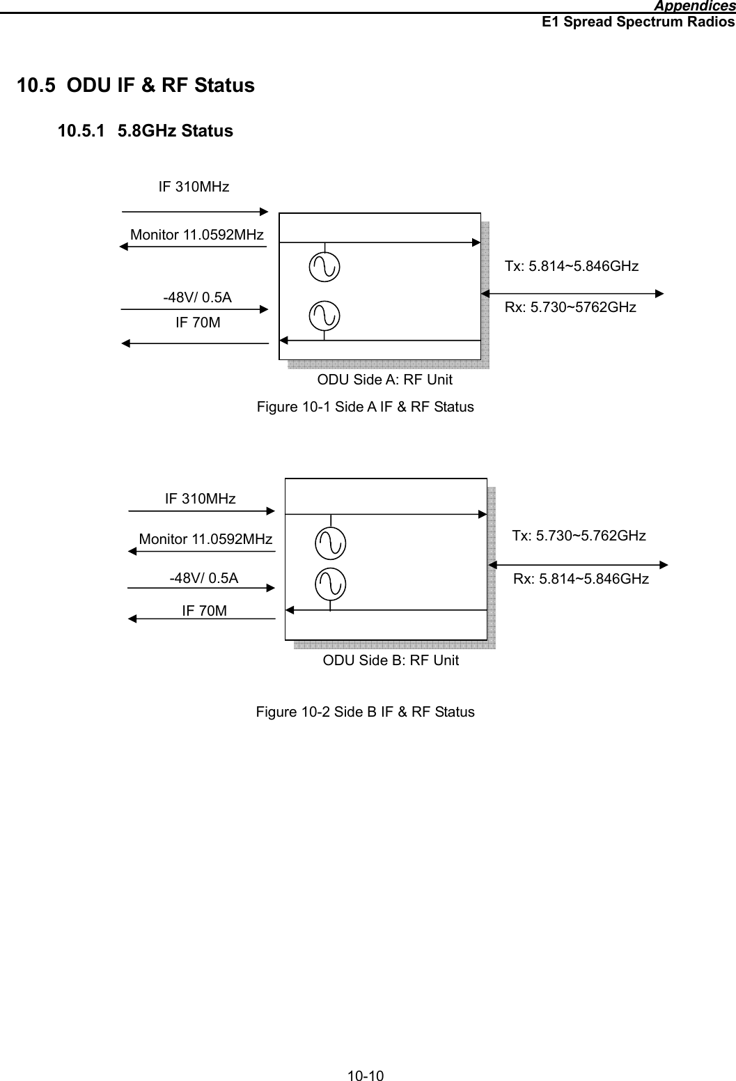
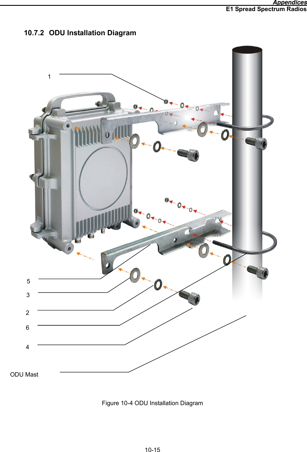
![Appendices E1 Spread Spectrum Radios 10-14 10.7 Installation Guide 10.7.1 Parts of ODU assembly Nut[1] Split Washer[2] Flat Washer[3] Hex Screw[4] ODU Fastening Assembly Figure 10-3 Part accessories Part Q’TY Nut[1] 4 Split Washer[2] 8 Flat Washer[3] 8 Hex Screw[4] 4 Mounting Bracket[5] 2 U-Bracket[6] 2 Mounting Bracket [5] U-Bracket[6]](https://usermanual.wiki/K-Best-Technology/5117R.User-Manual-2/User-Guide-517913-Page-51.png)