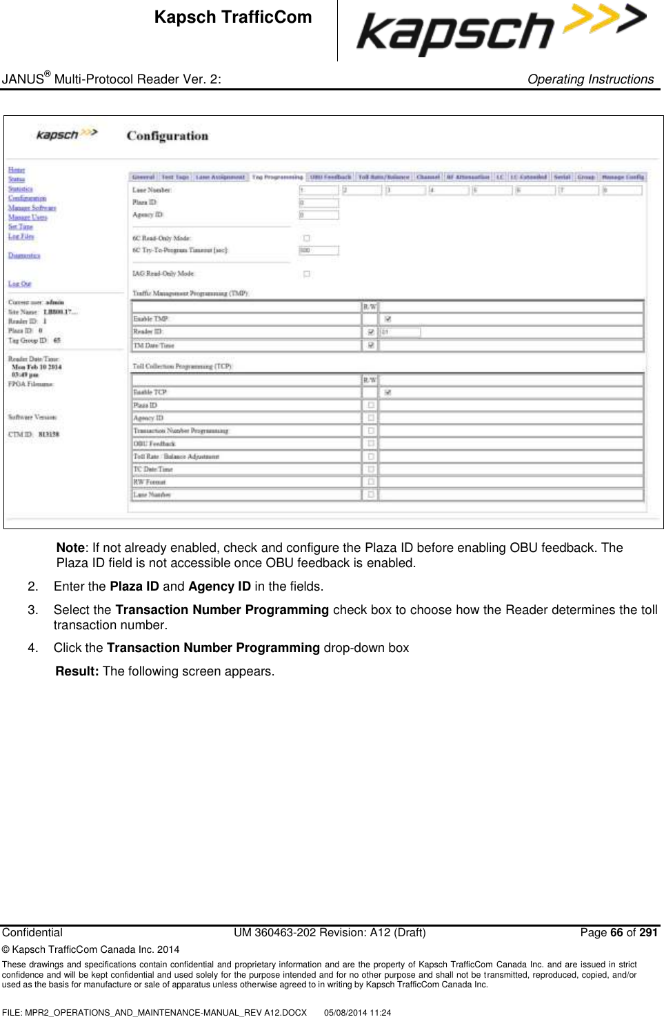
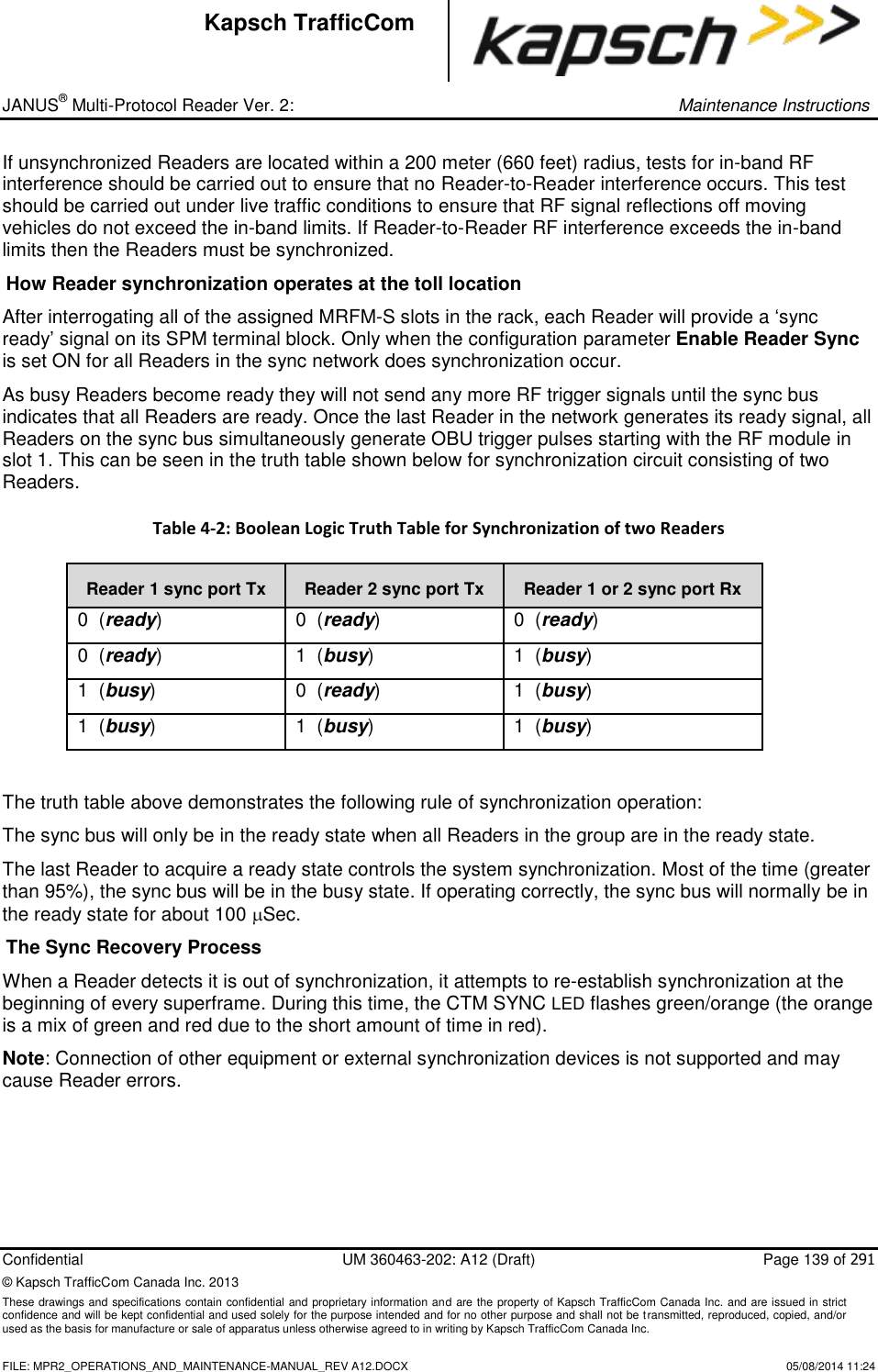
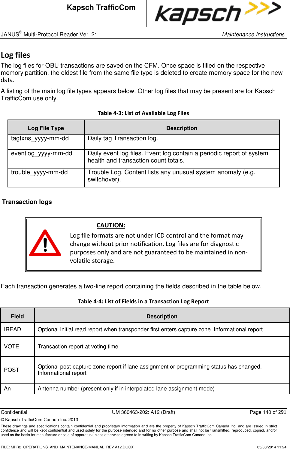
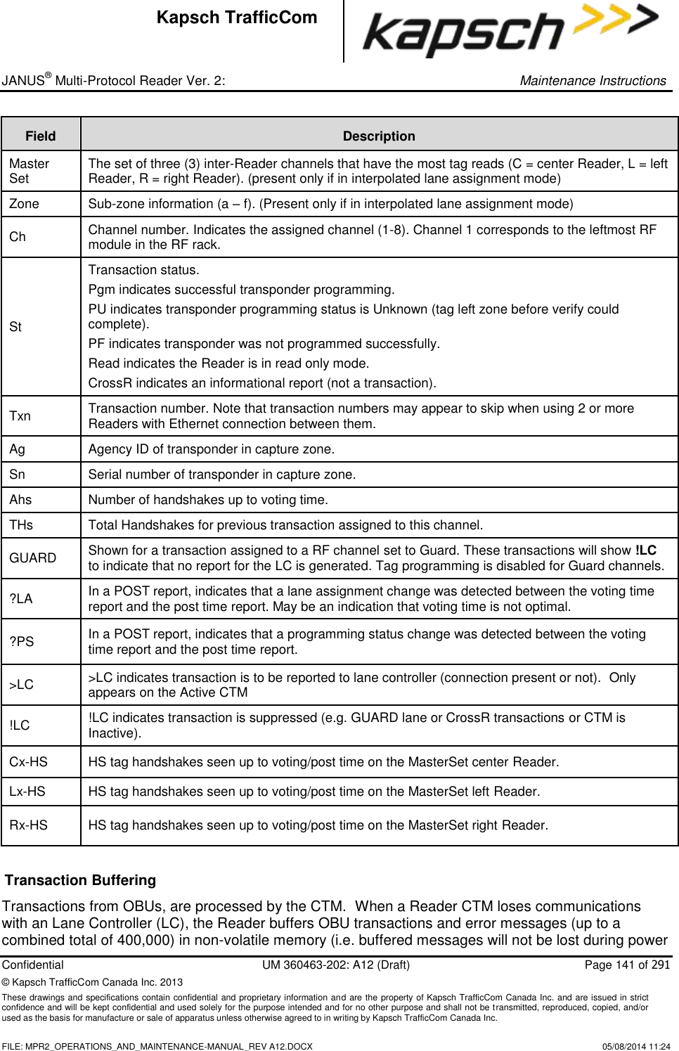
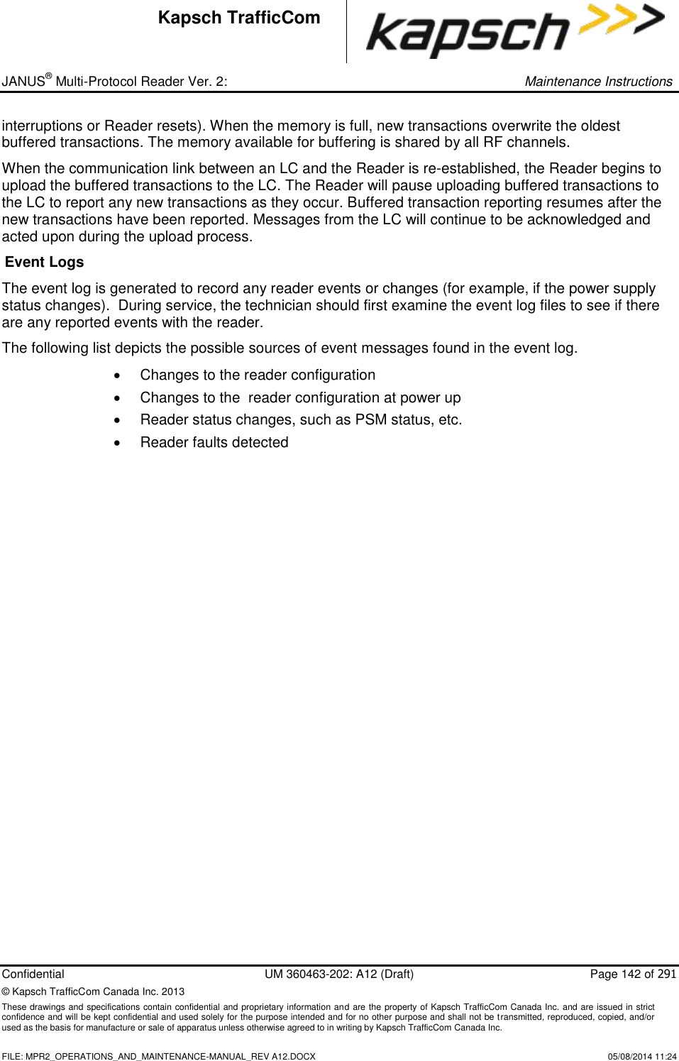
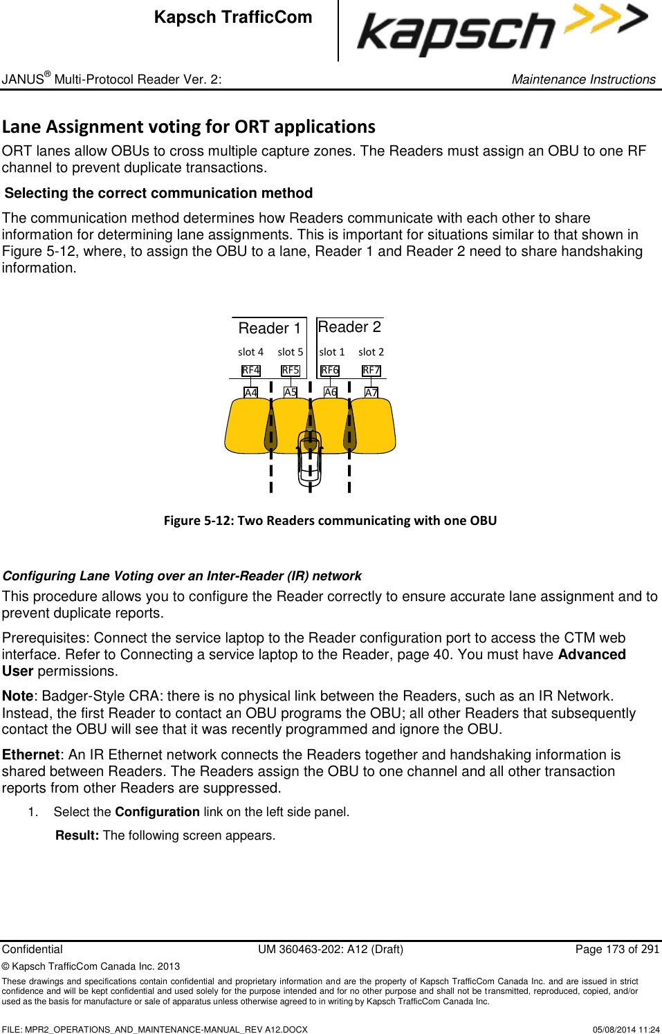
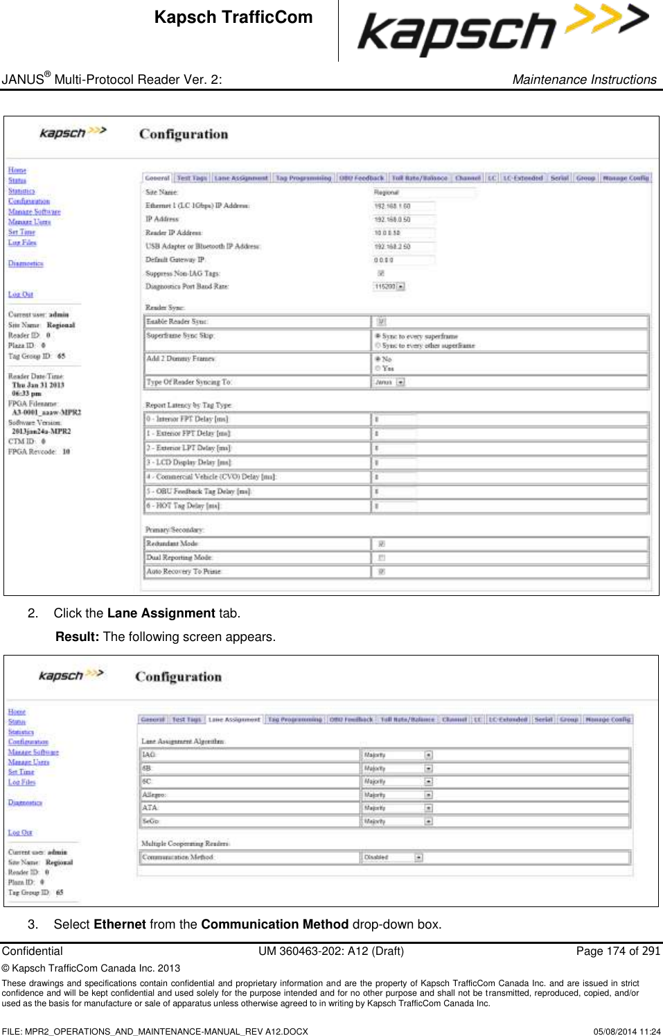
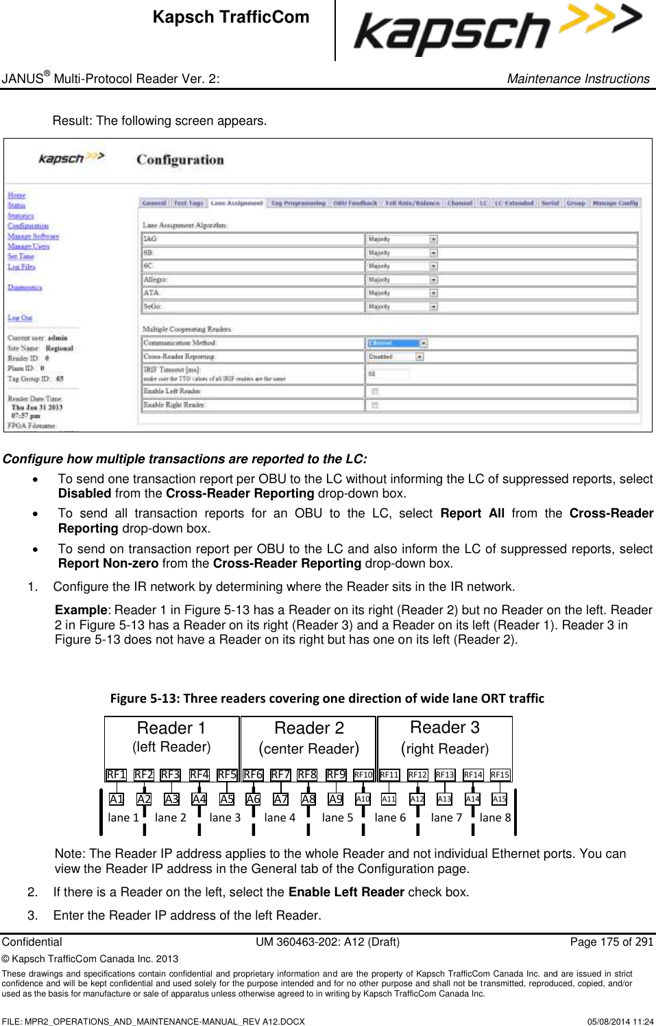
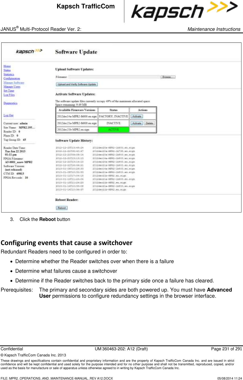
KAPSCH TRAFFICCOM CANADA 802295A Non-multilateration LMS transmitter and receiver User Manual Operator and Maintenance Manual
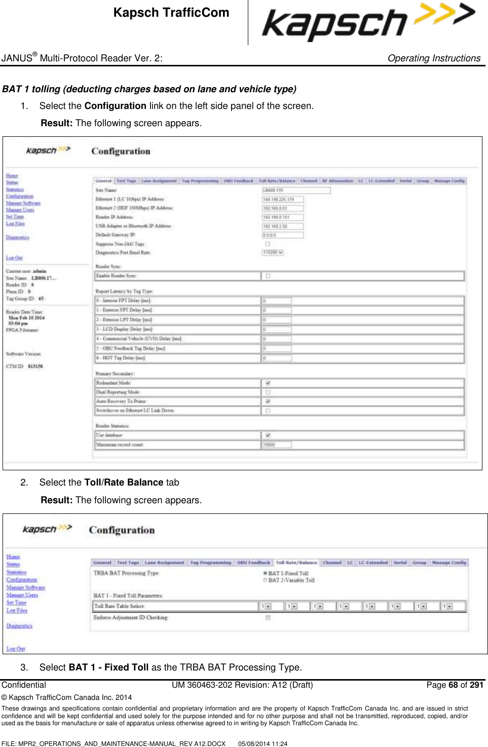
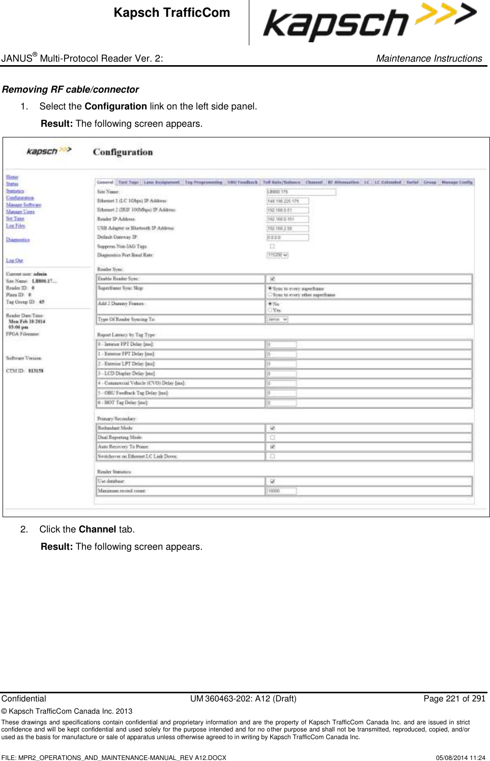
KAPSCH TRAFFICCOM CANADA INC. Non-multilateration LMS transmitter and receiver Operator and Maintenance Manual
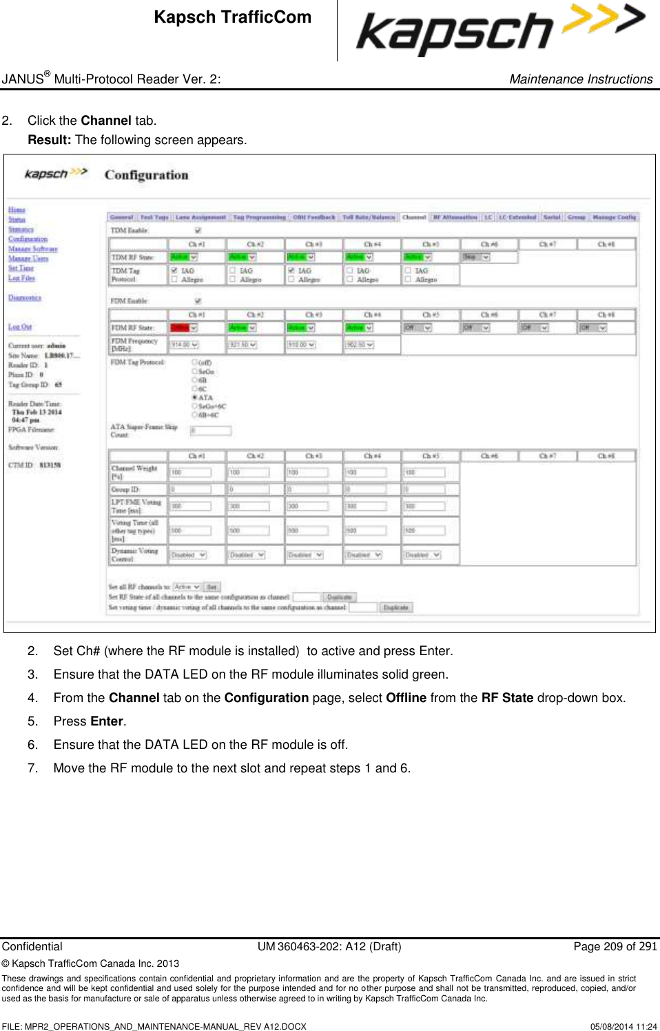
Contents
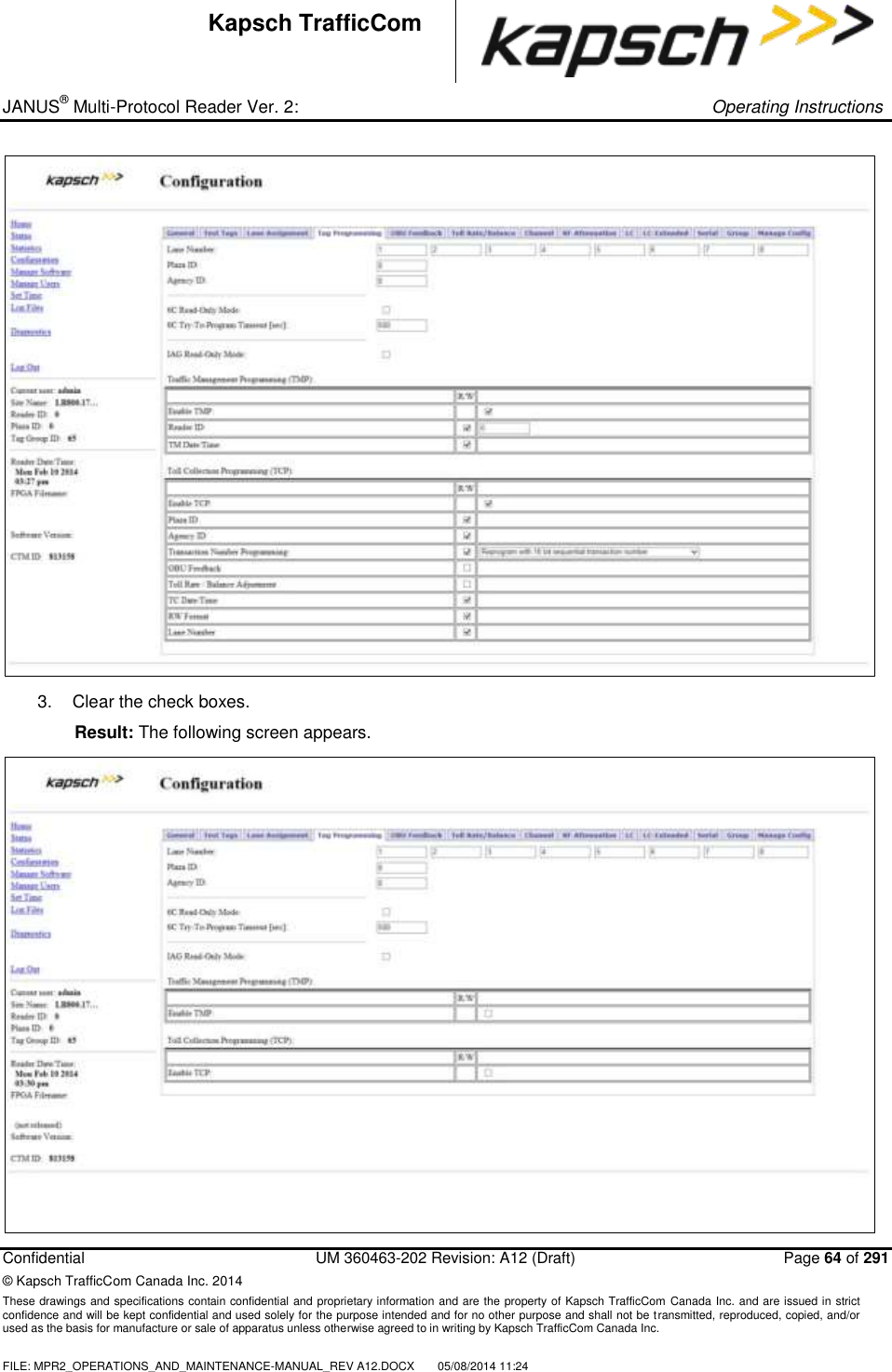
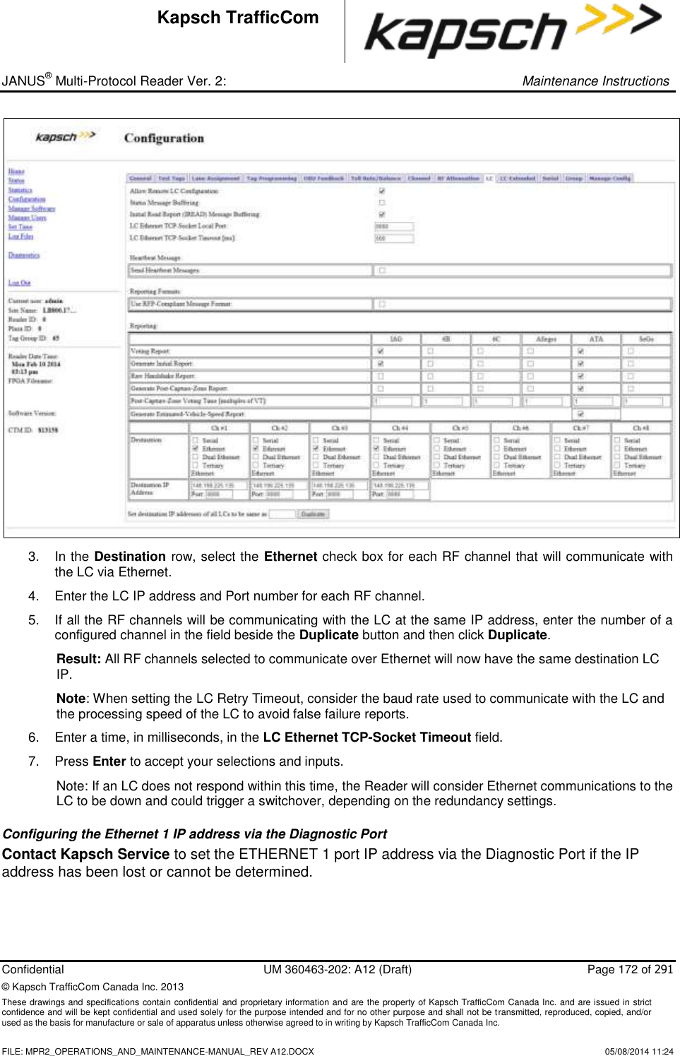
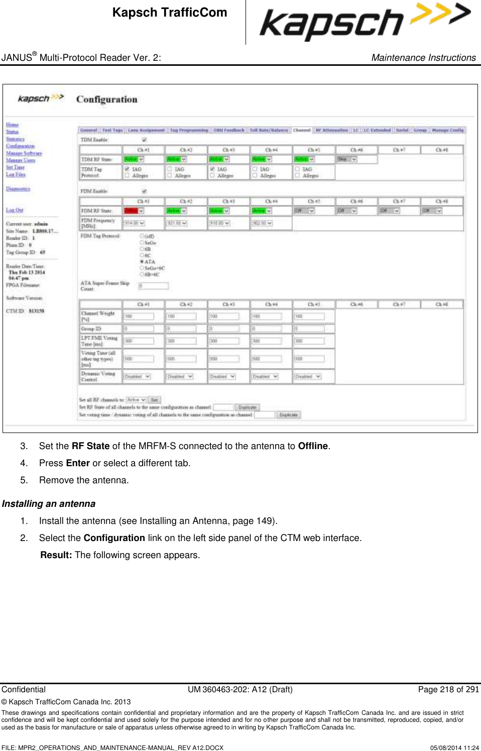
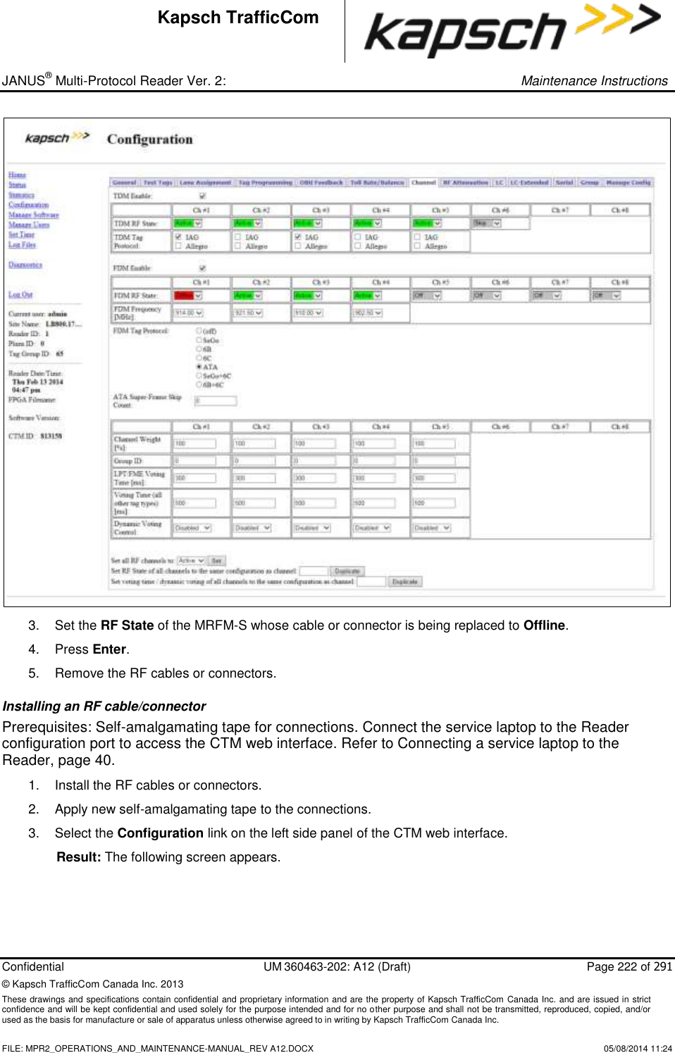
- 1. Operations and Maintenance Manual
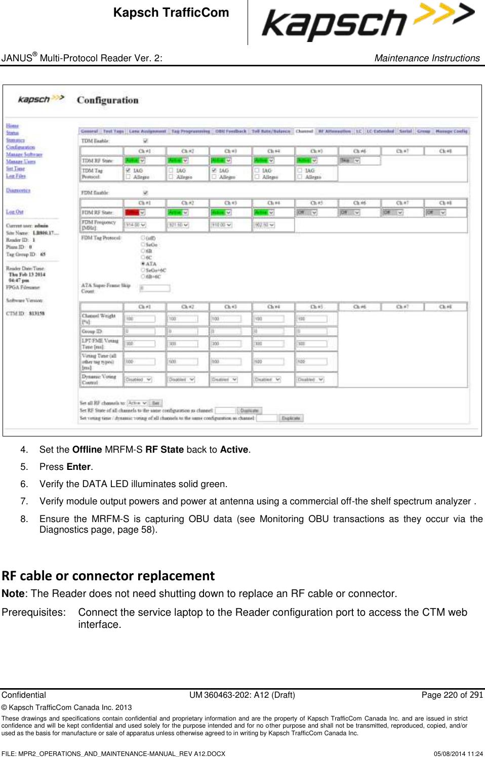
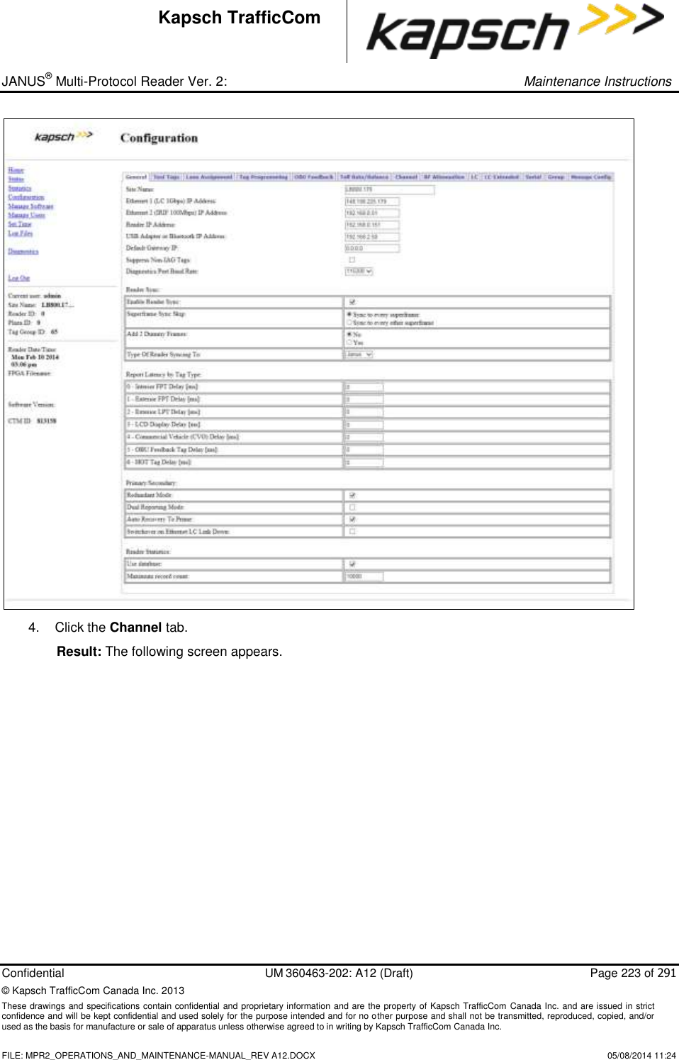
- 2. Users Manual
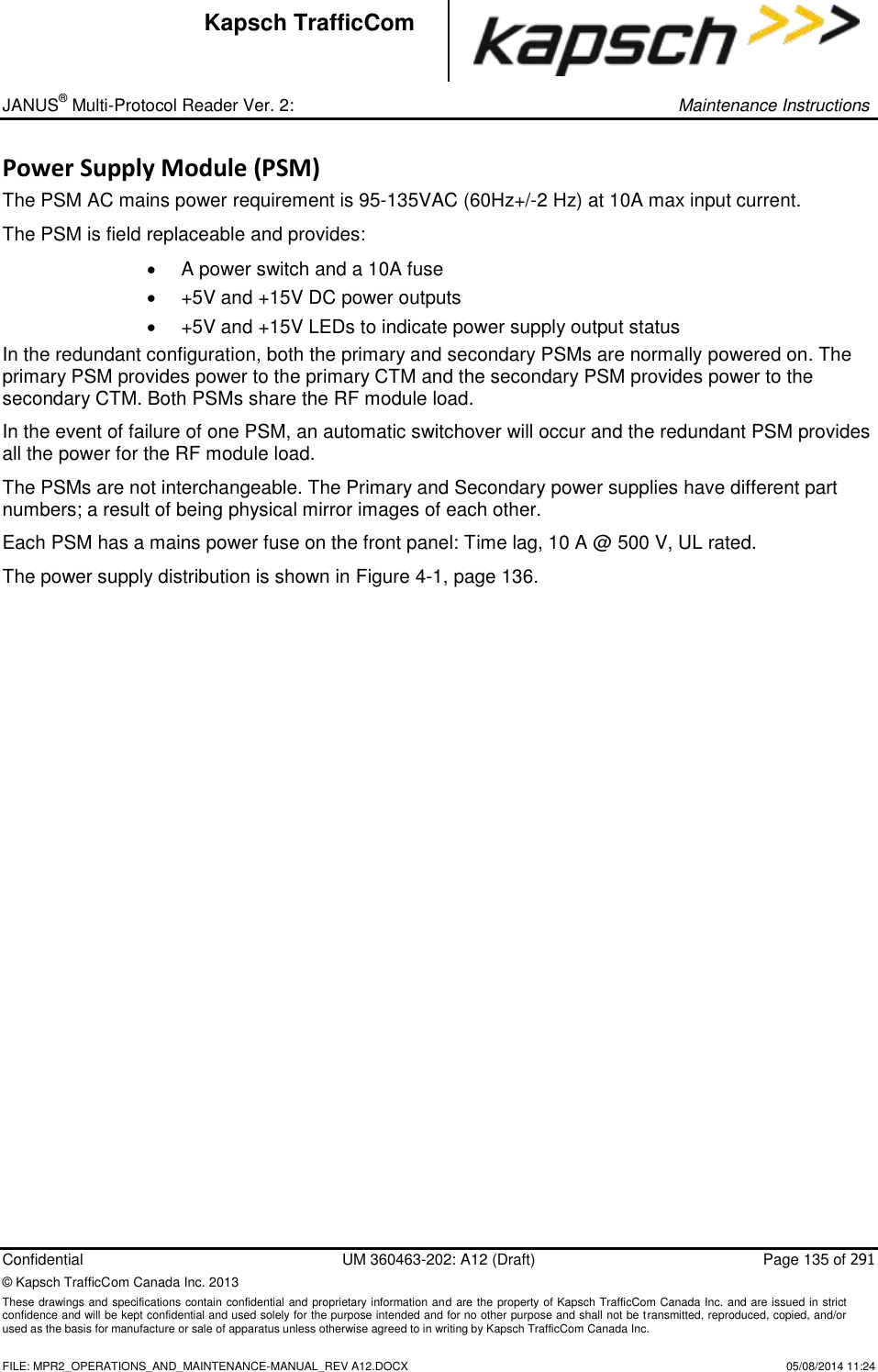
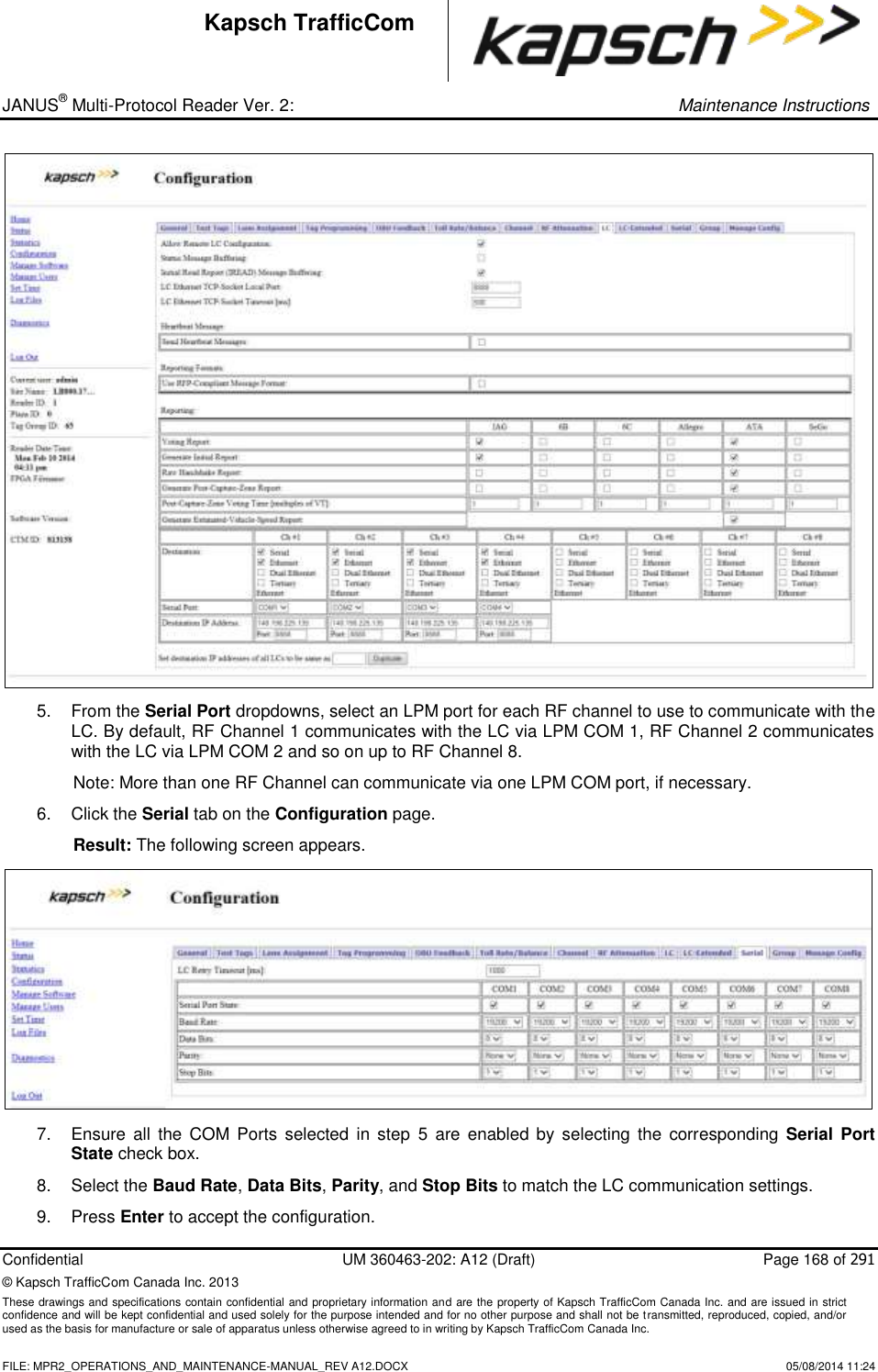
Operations and Maintenance Manual

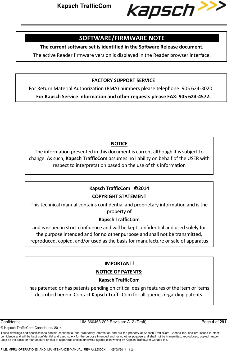


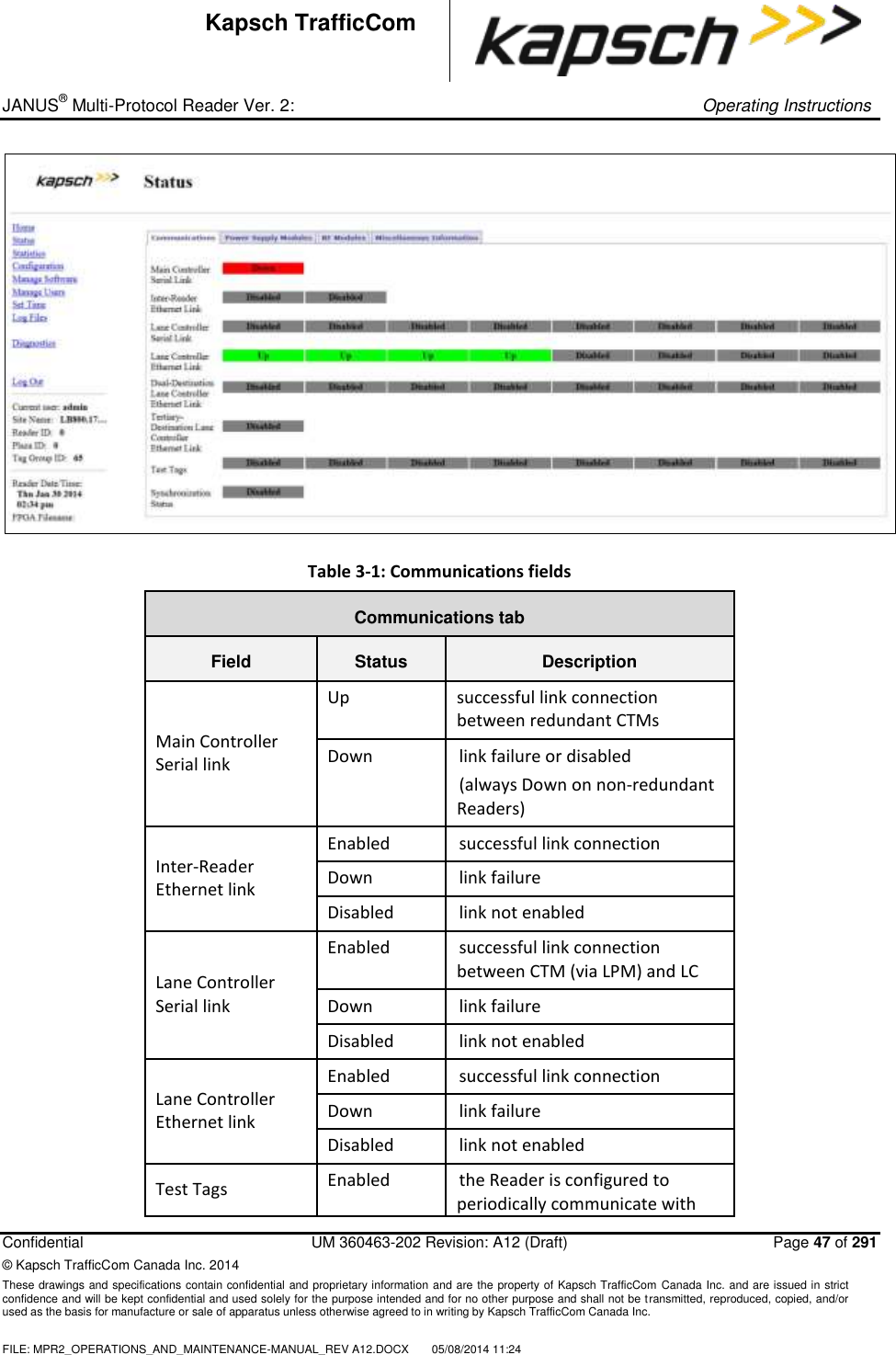

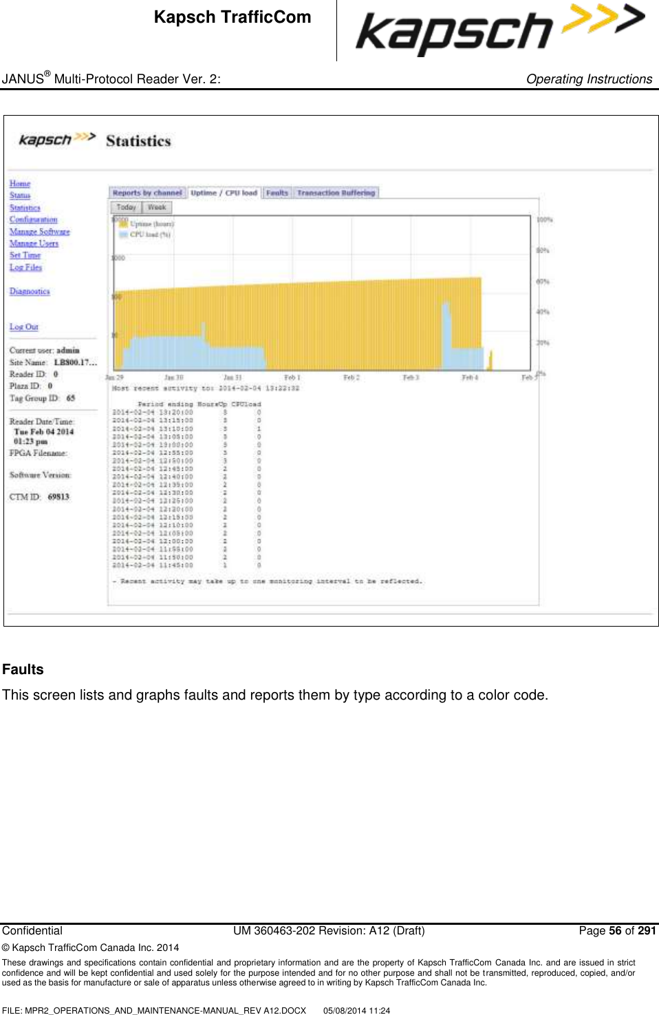
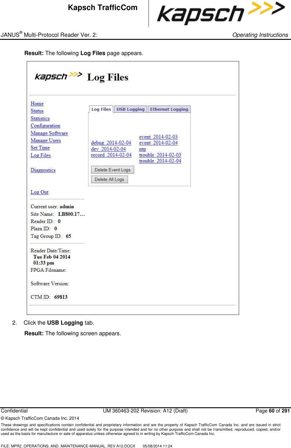
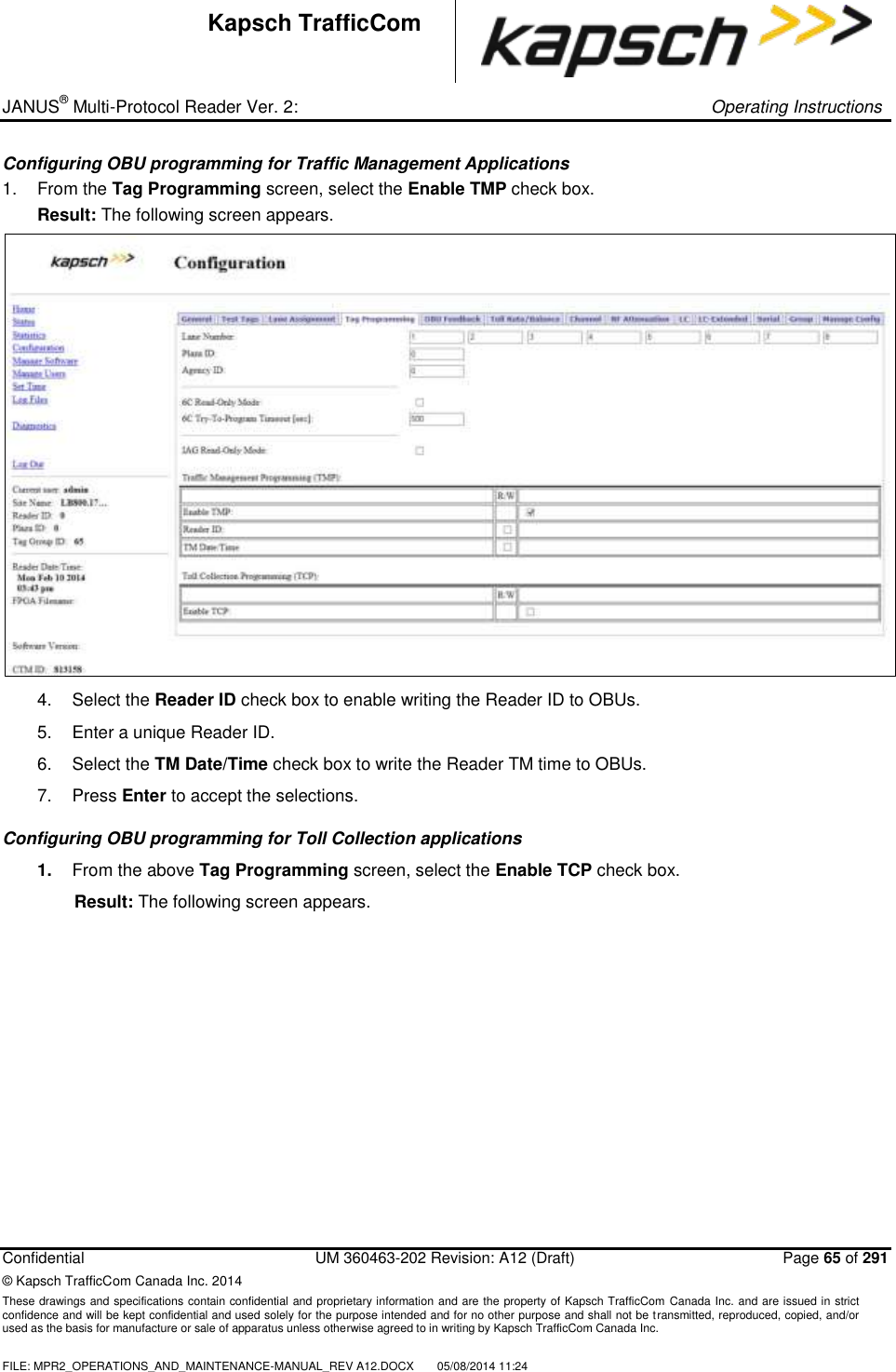
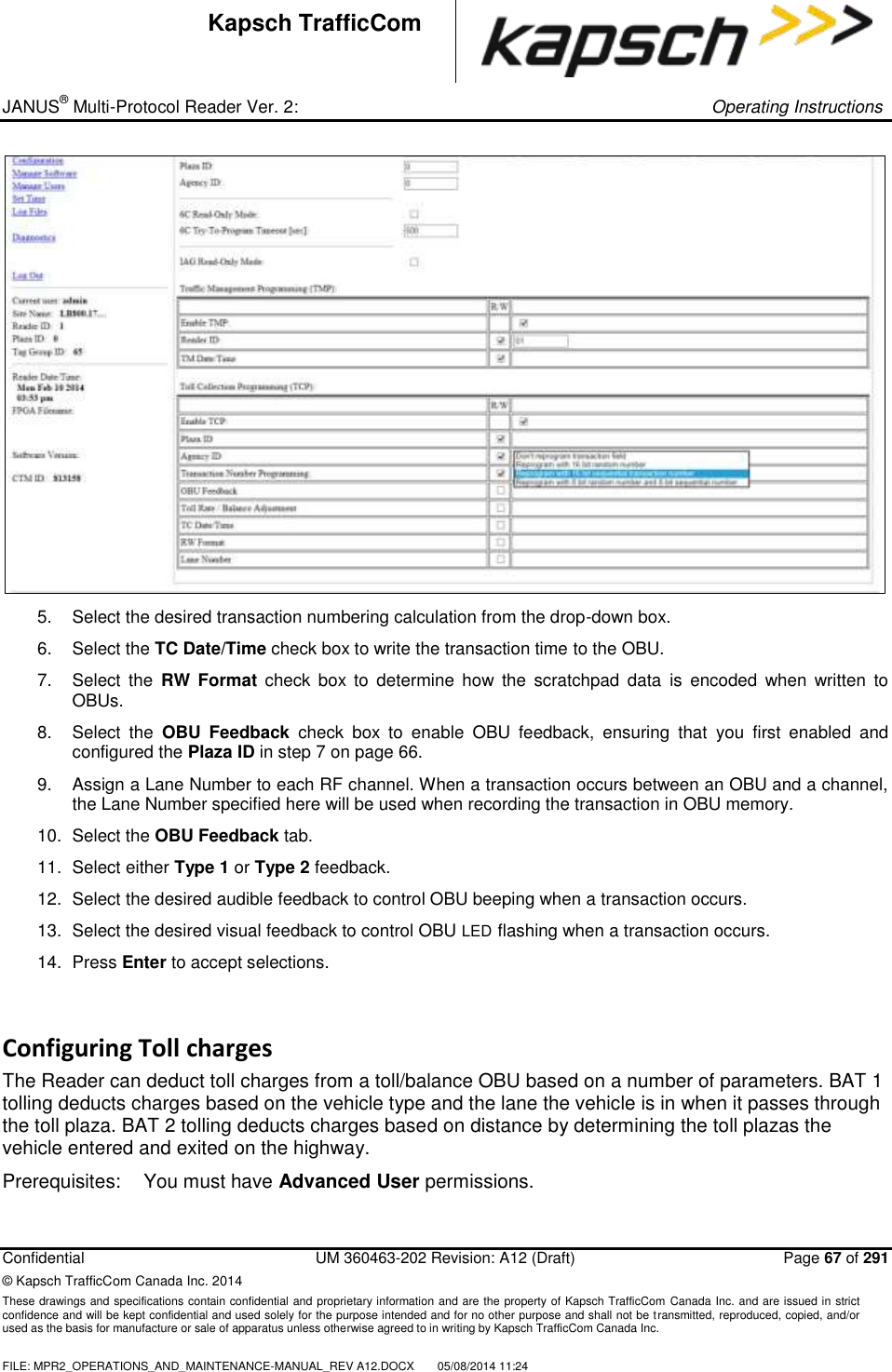
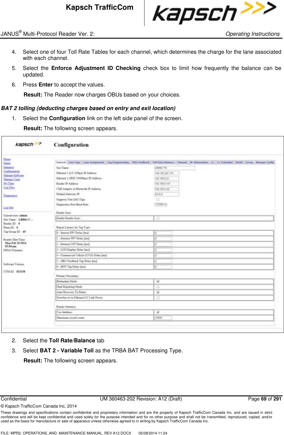
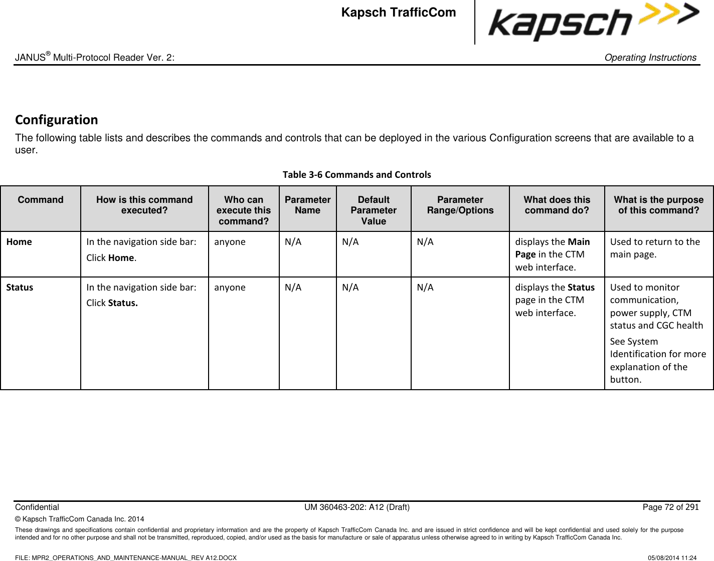
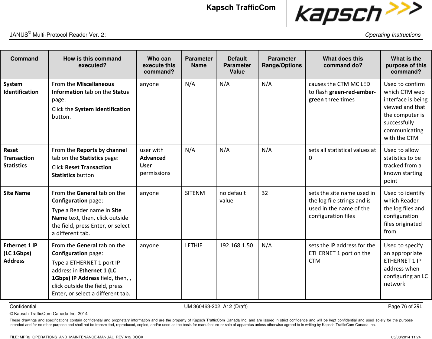
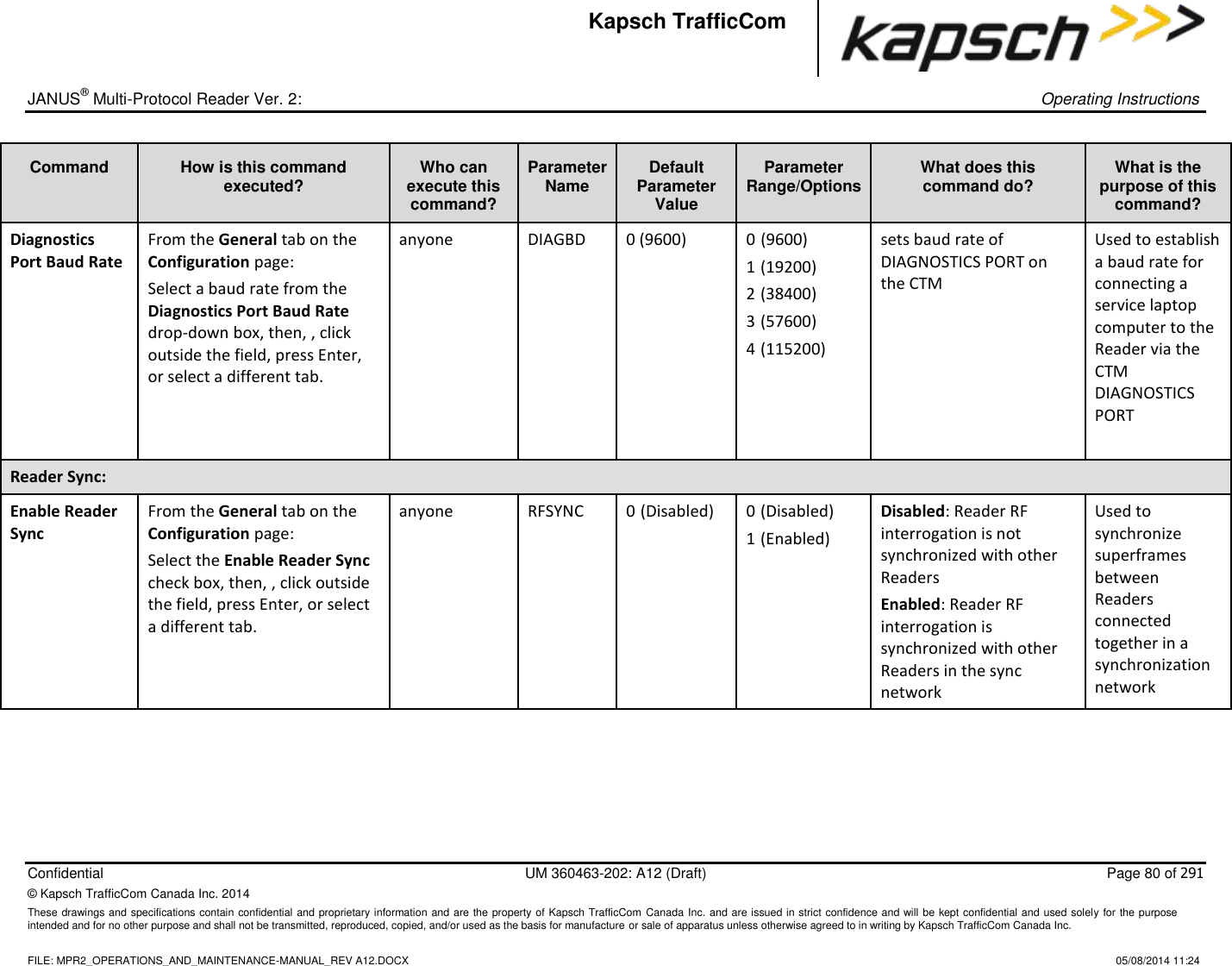
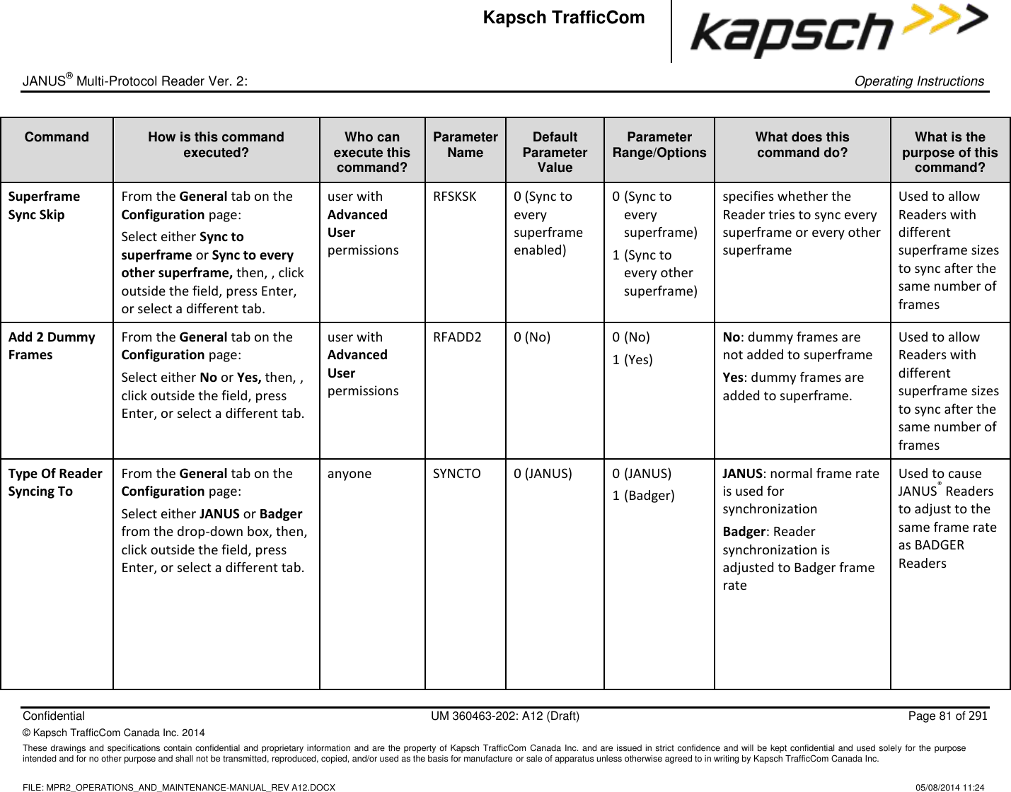
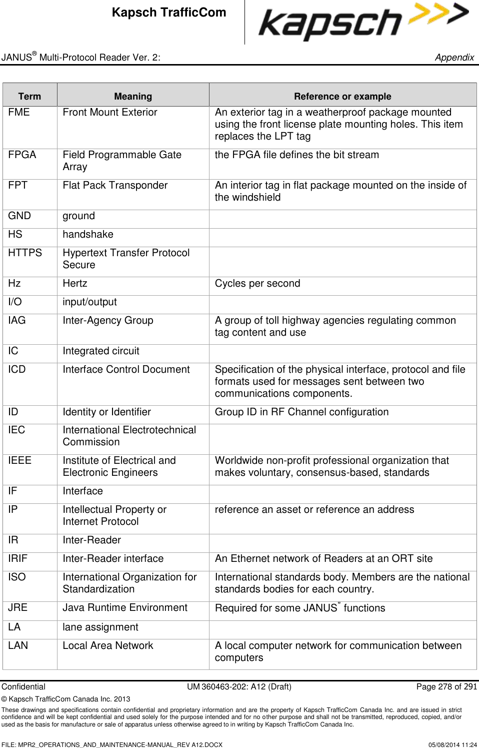
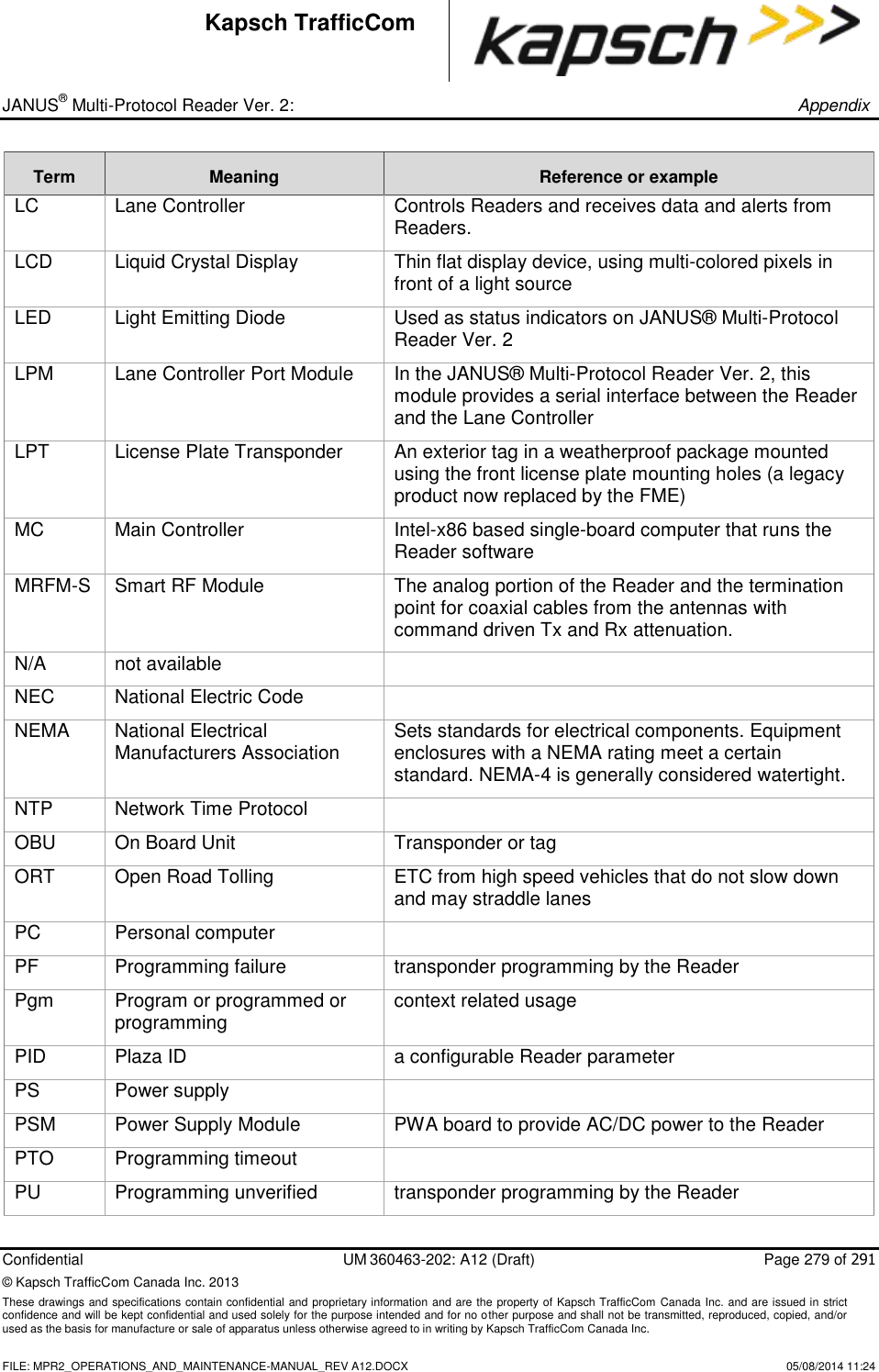
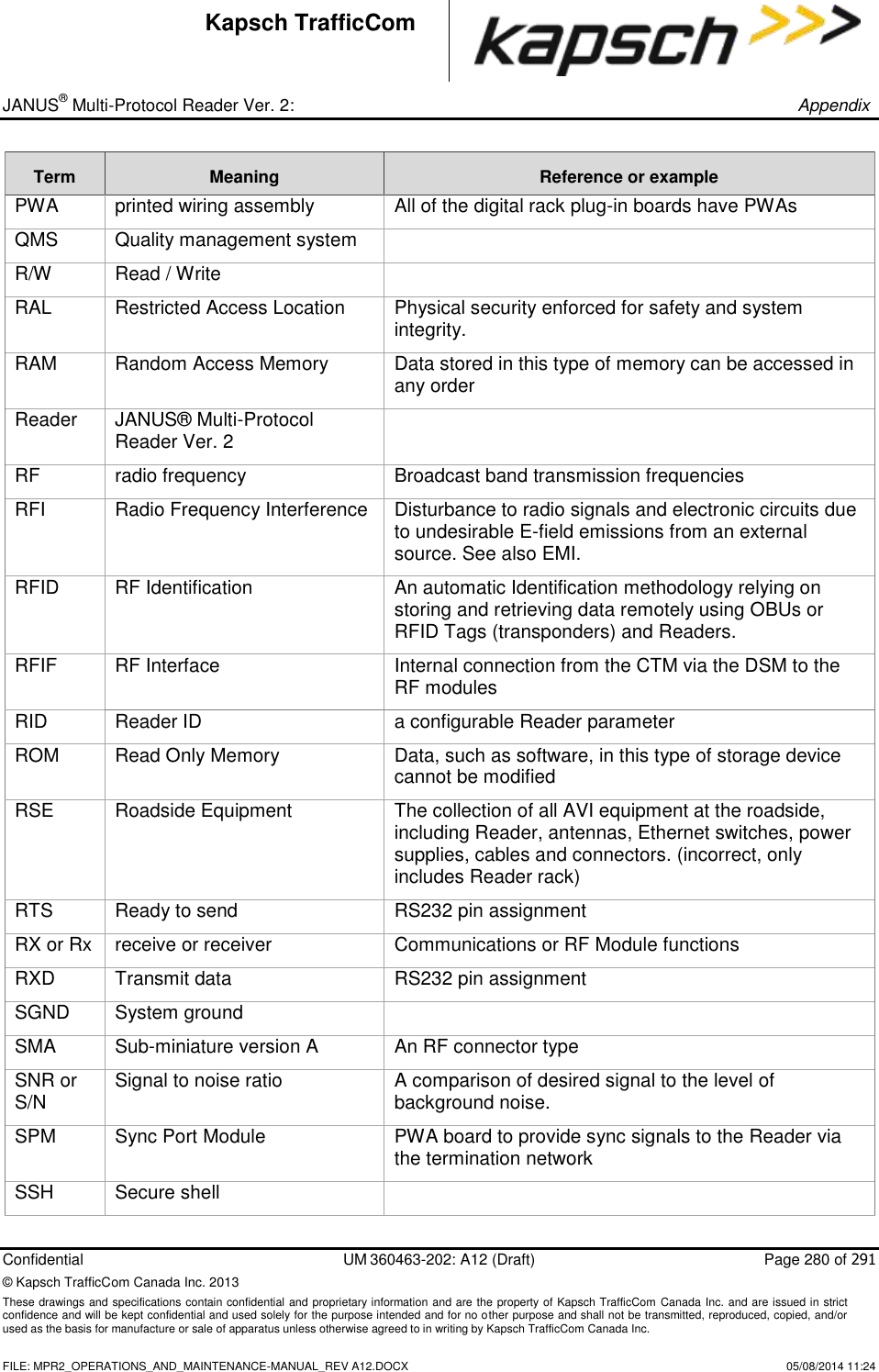
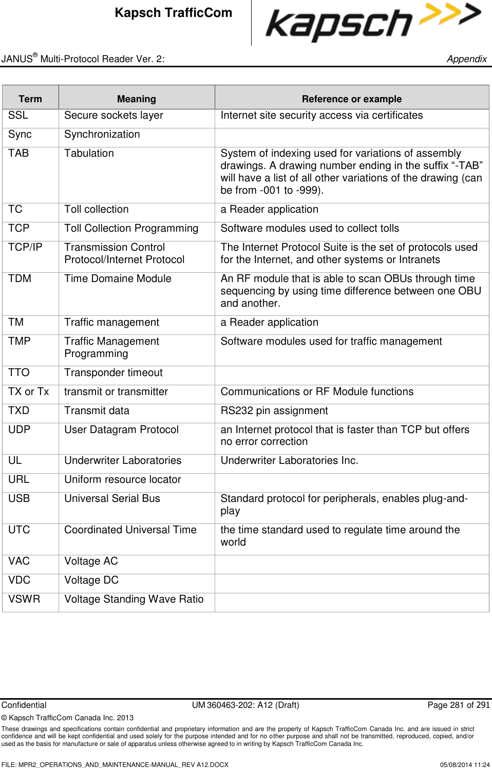
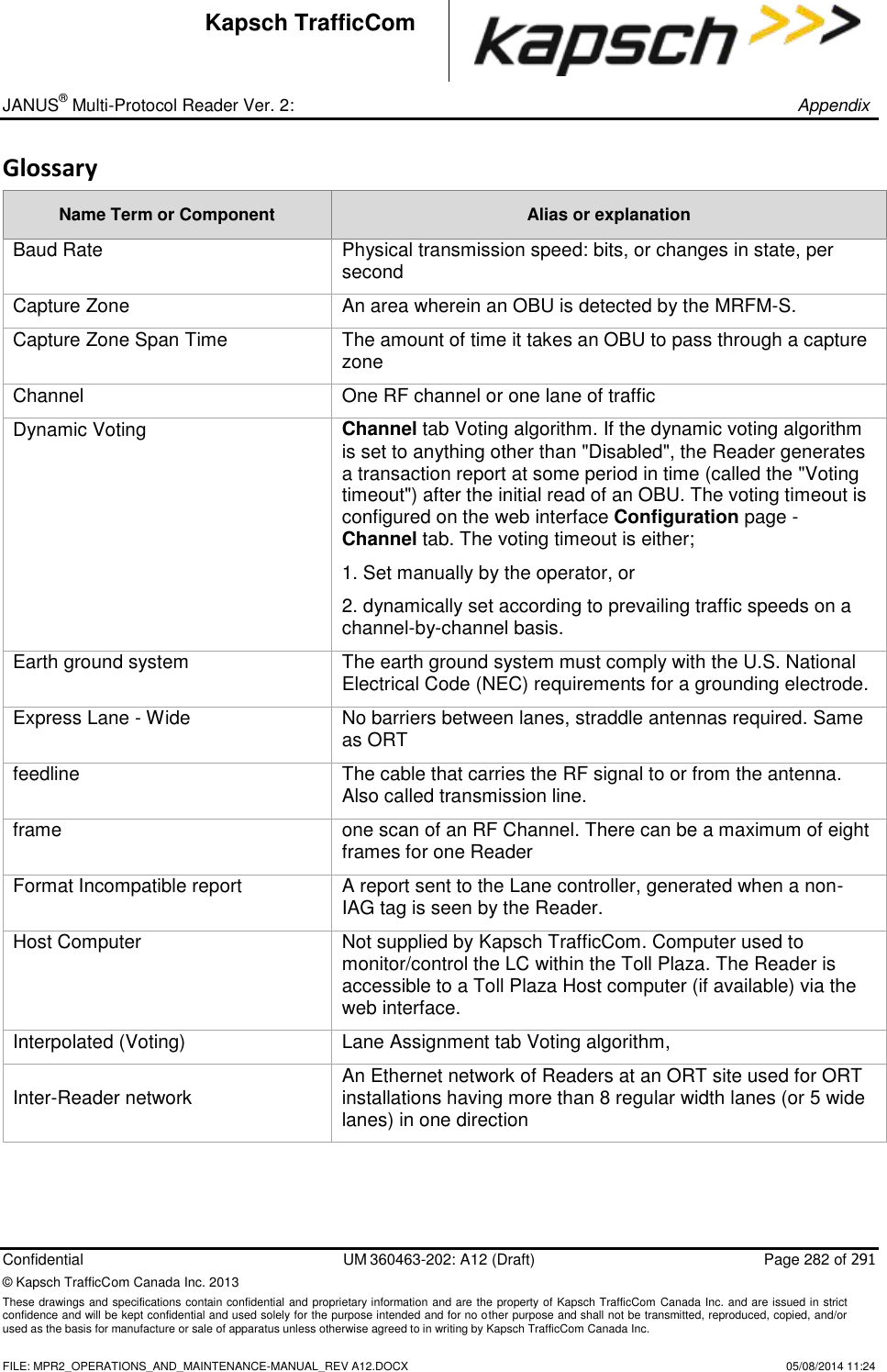
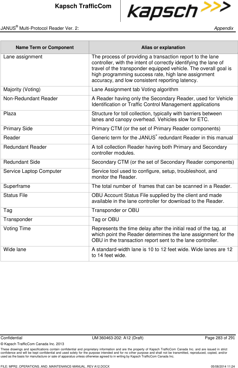
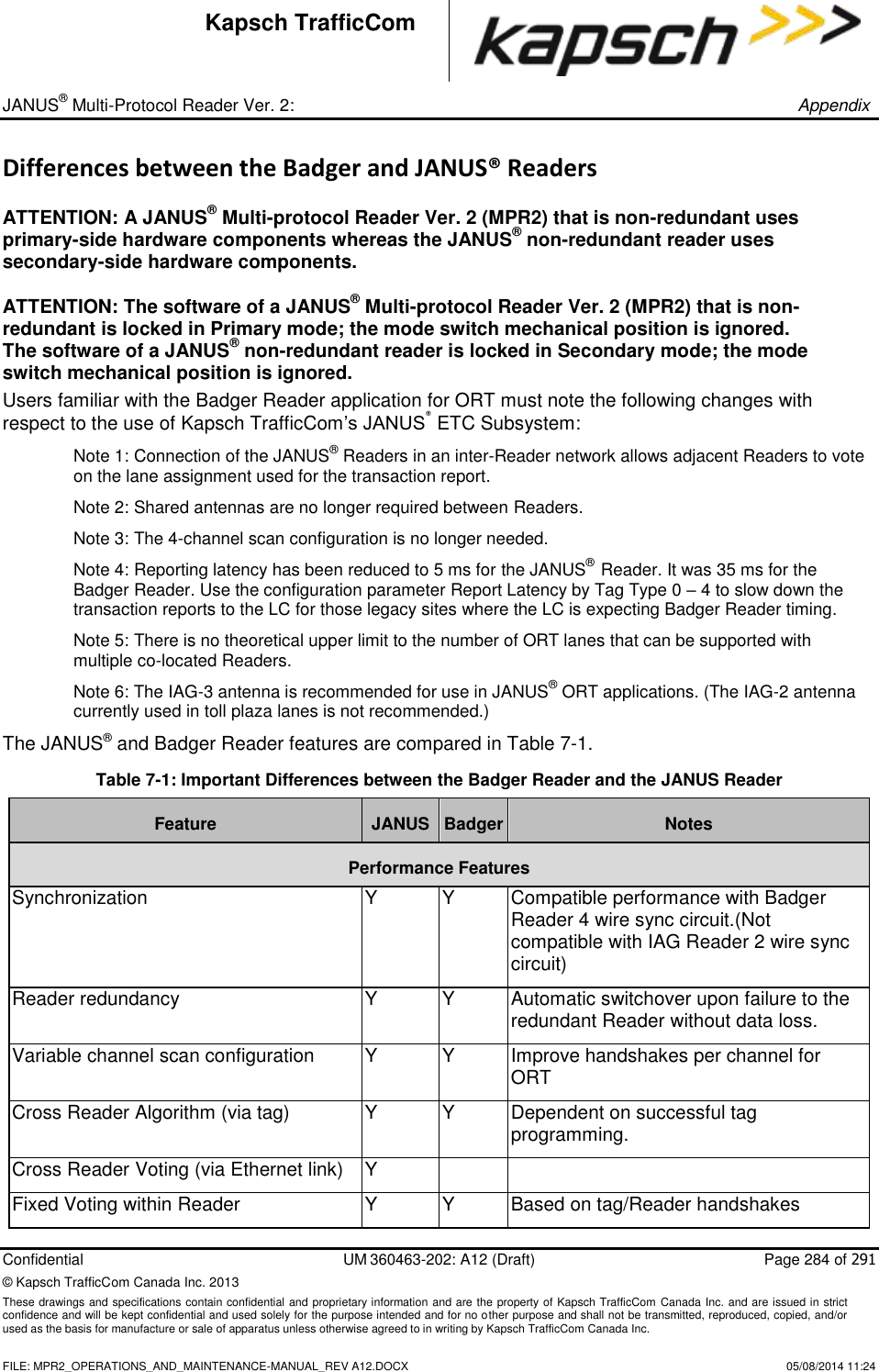
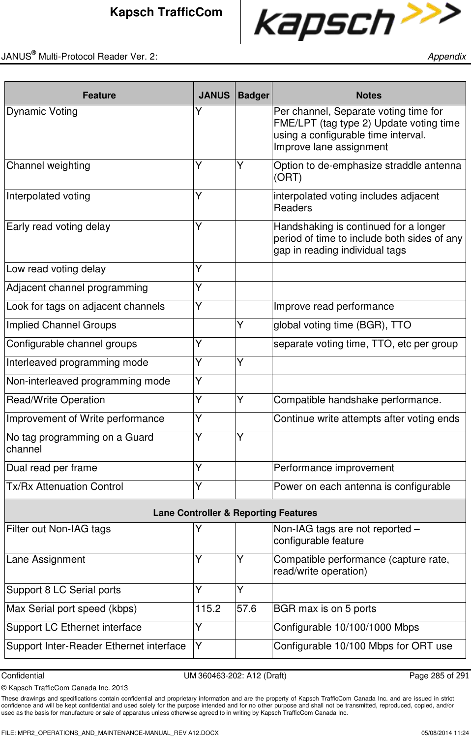
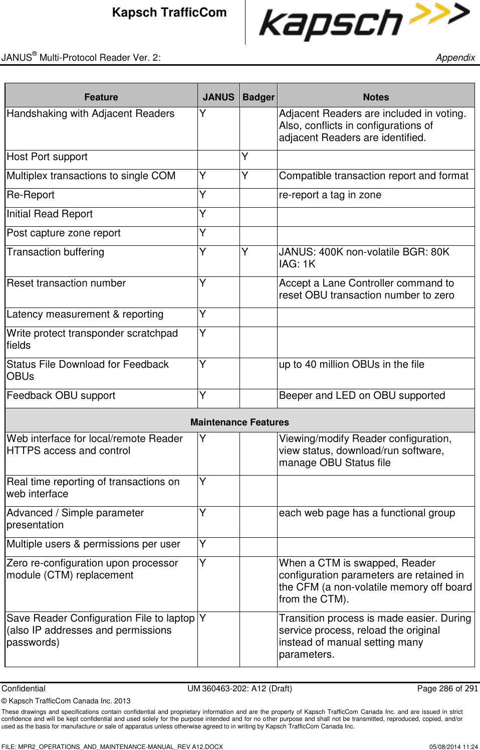
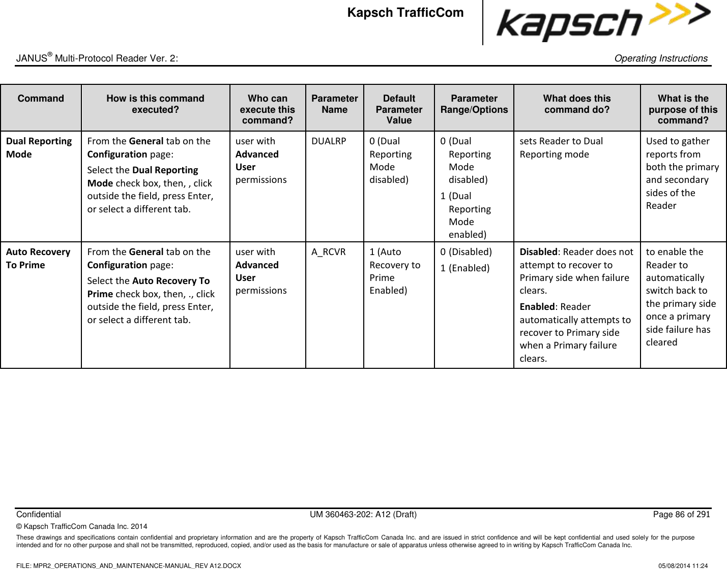
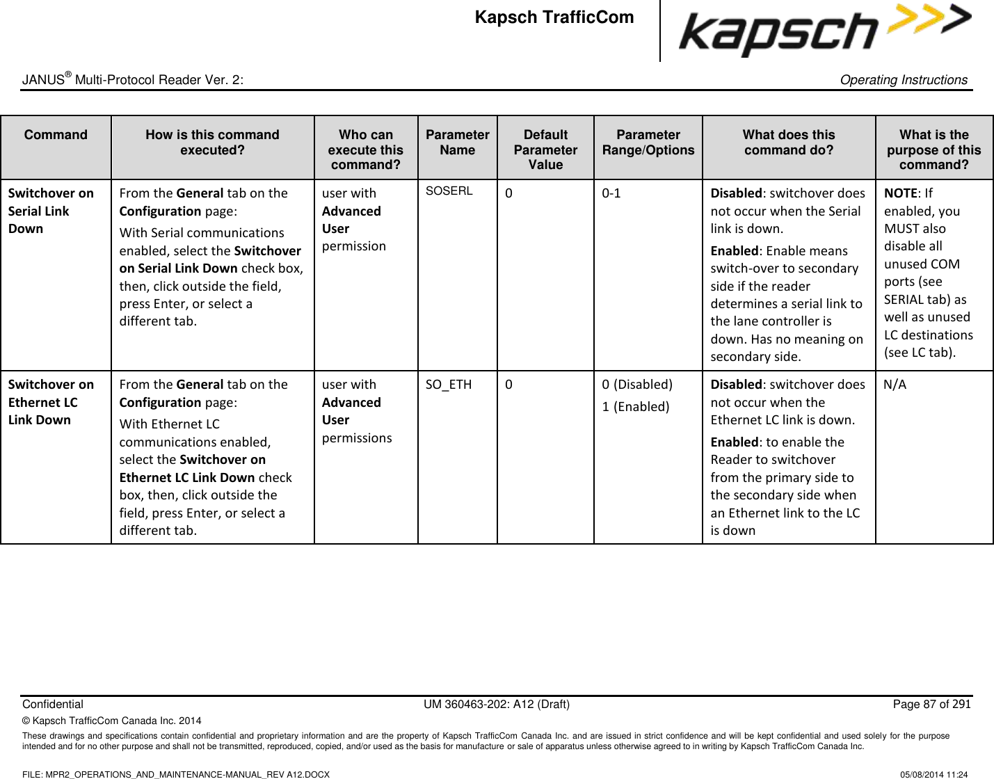
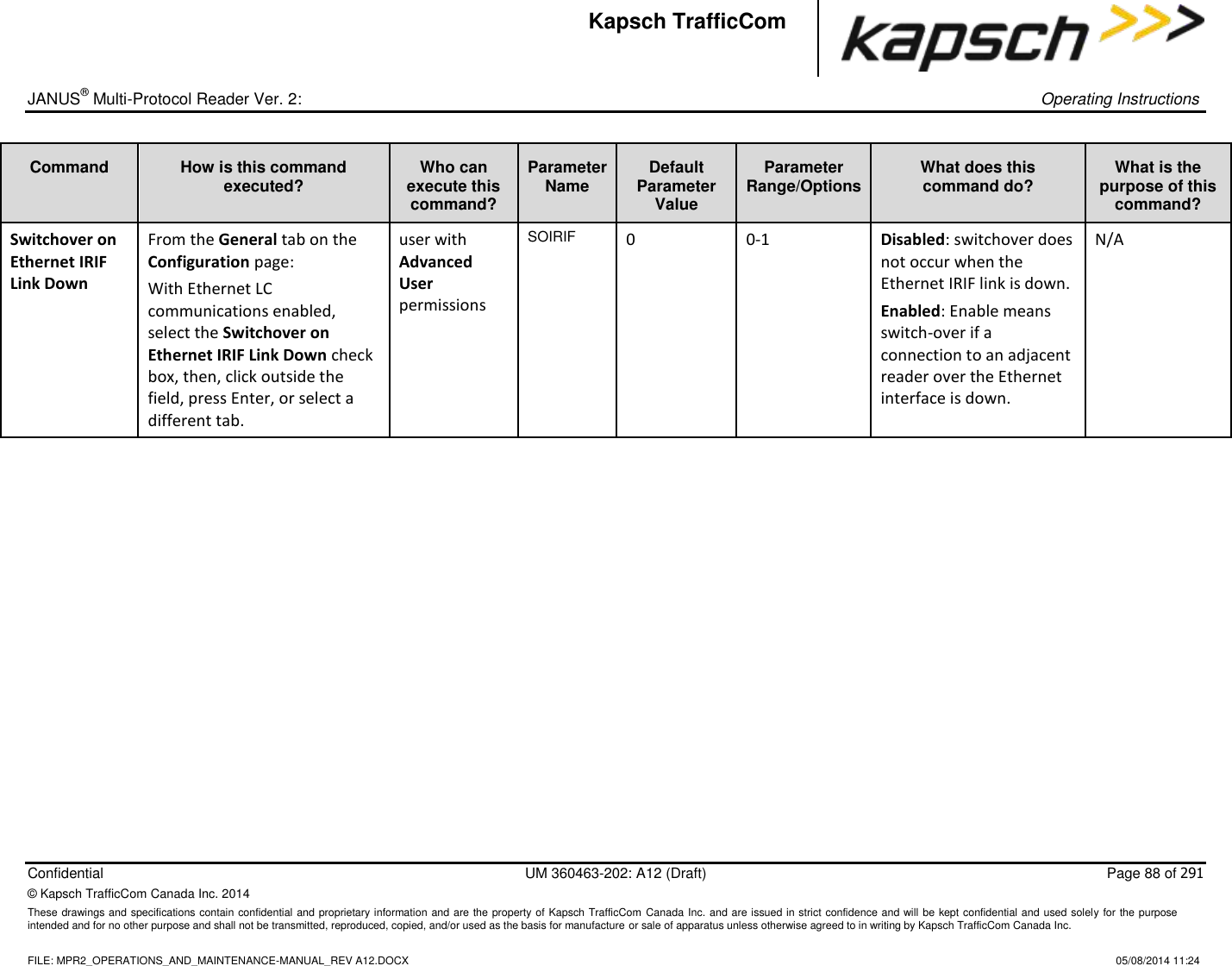
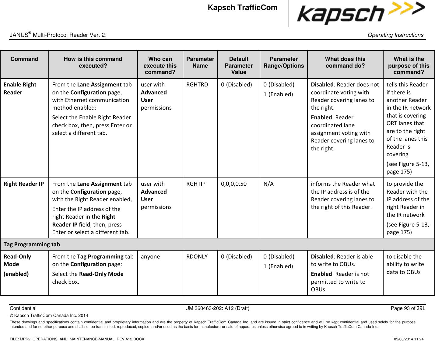
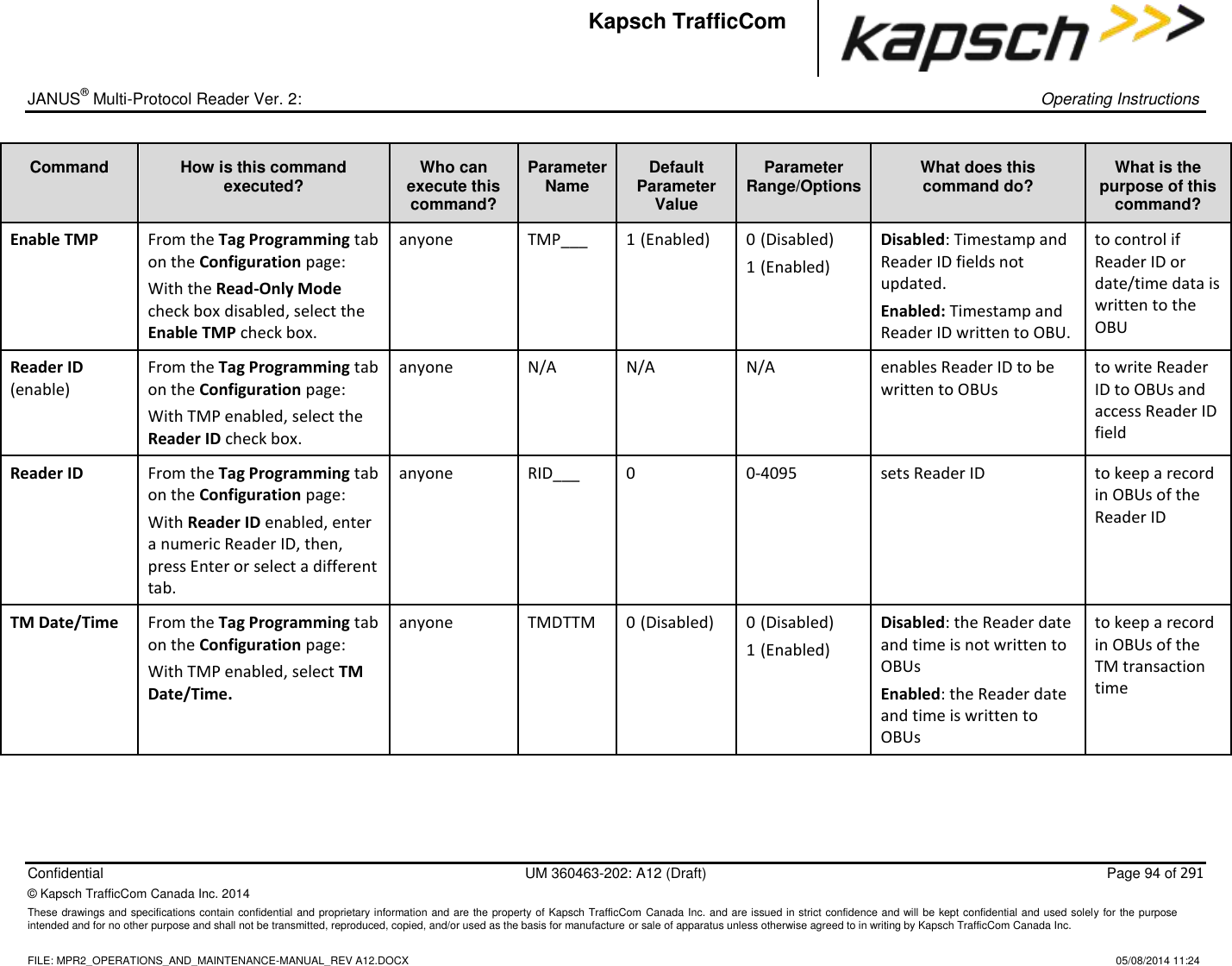
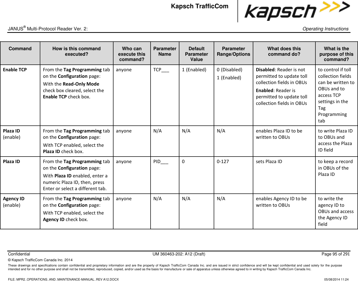
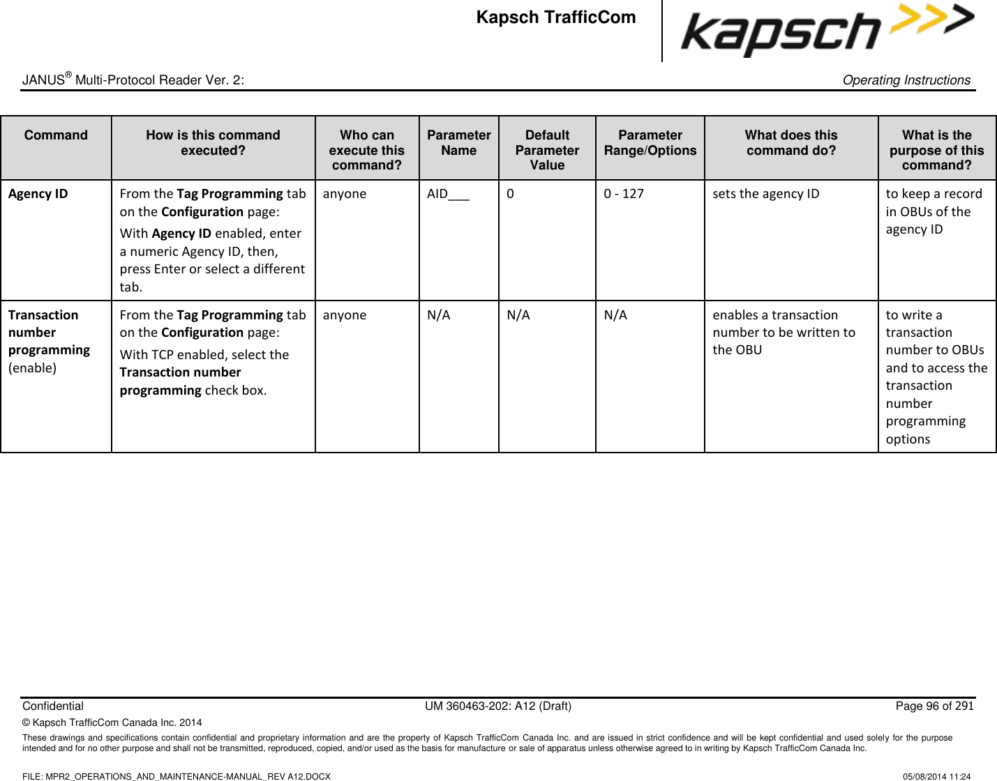
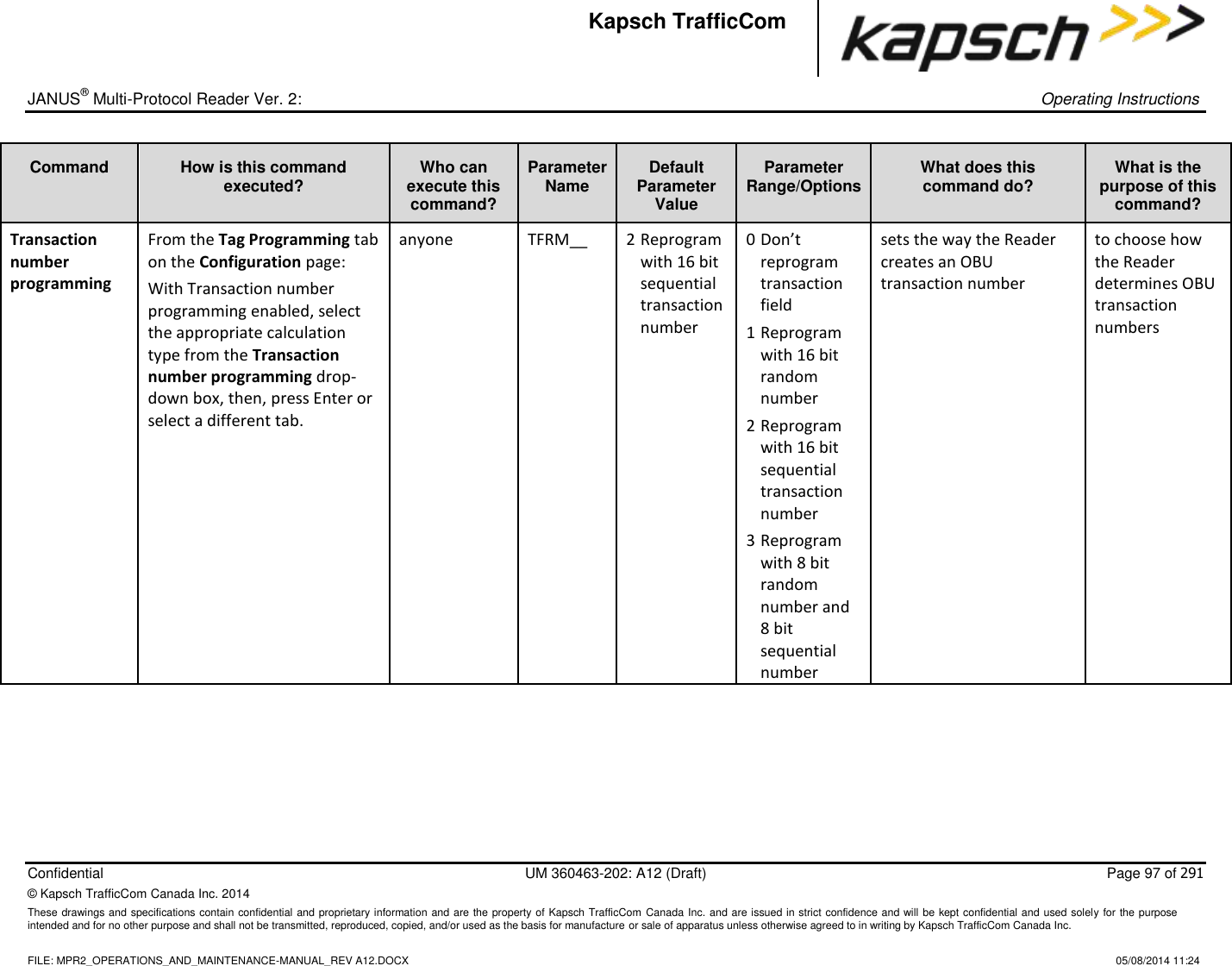
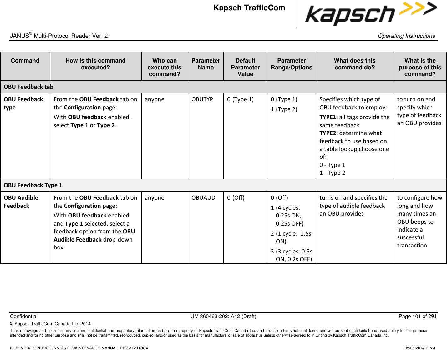
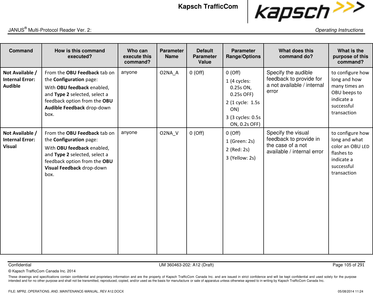
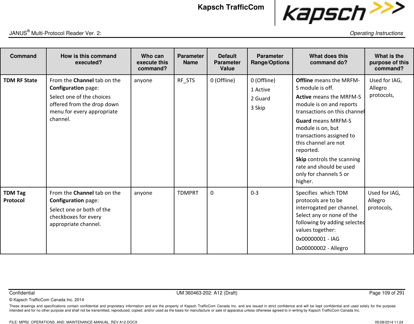
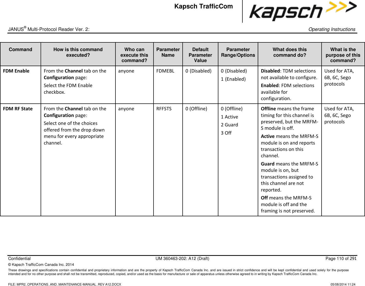
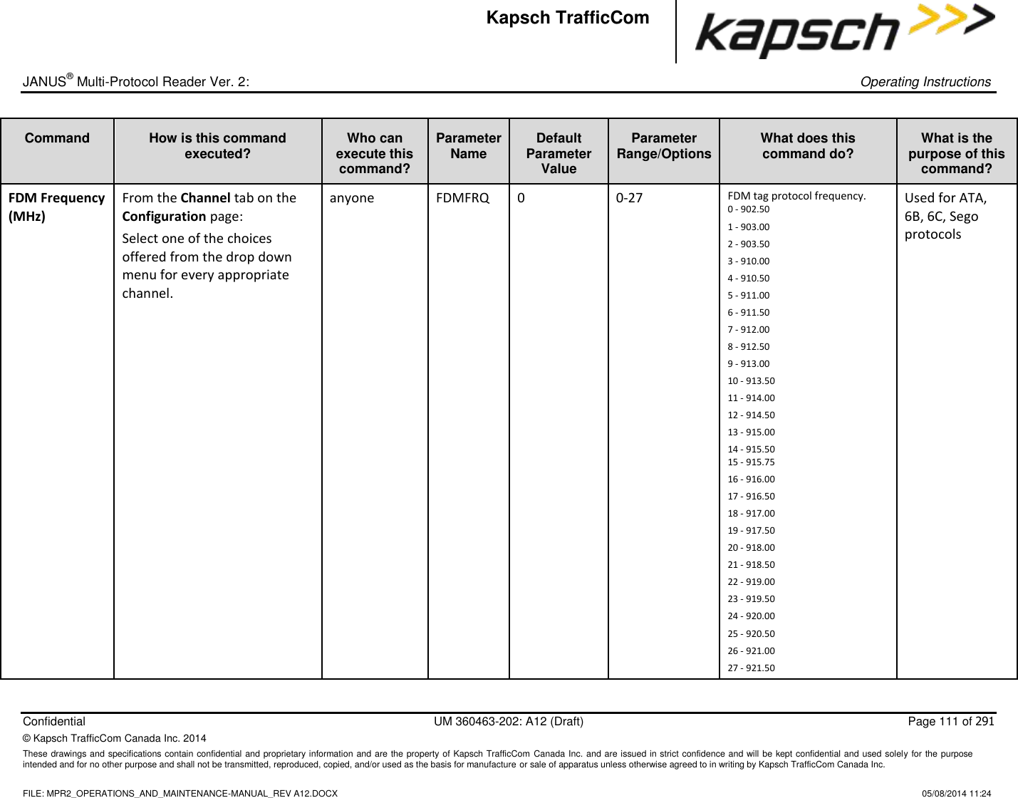
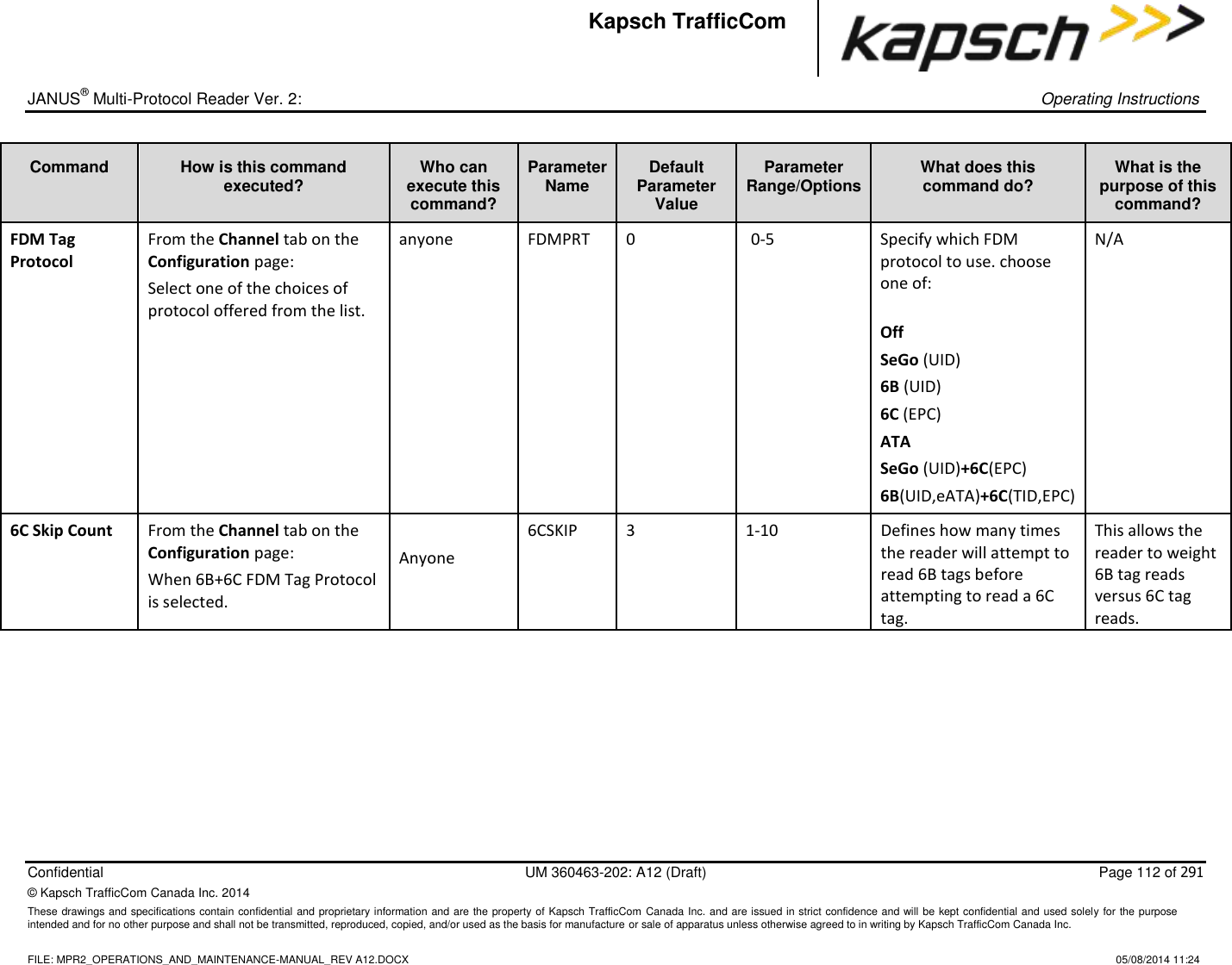
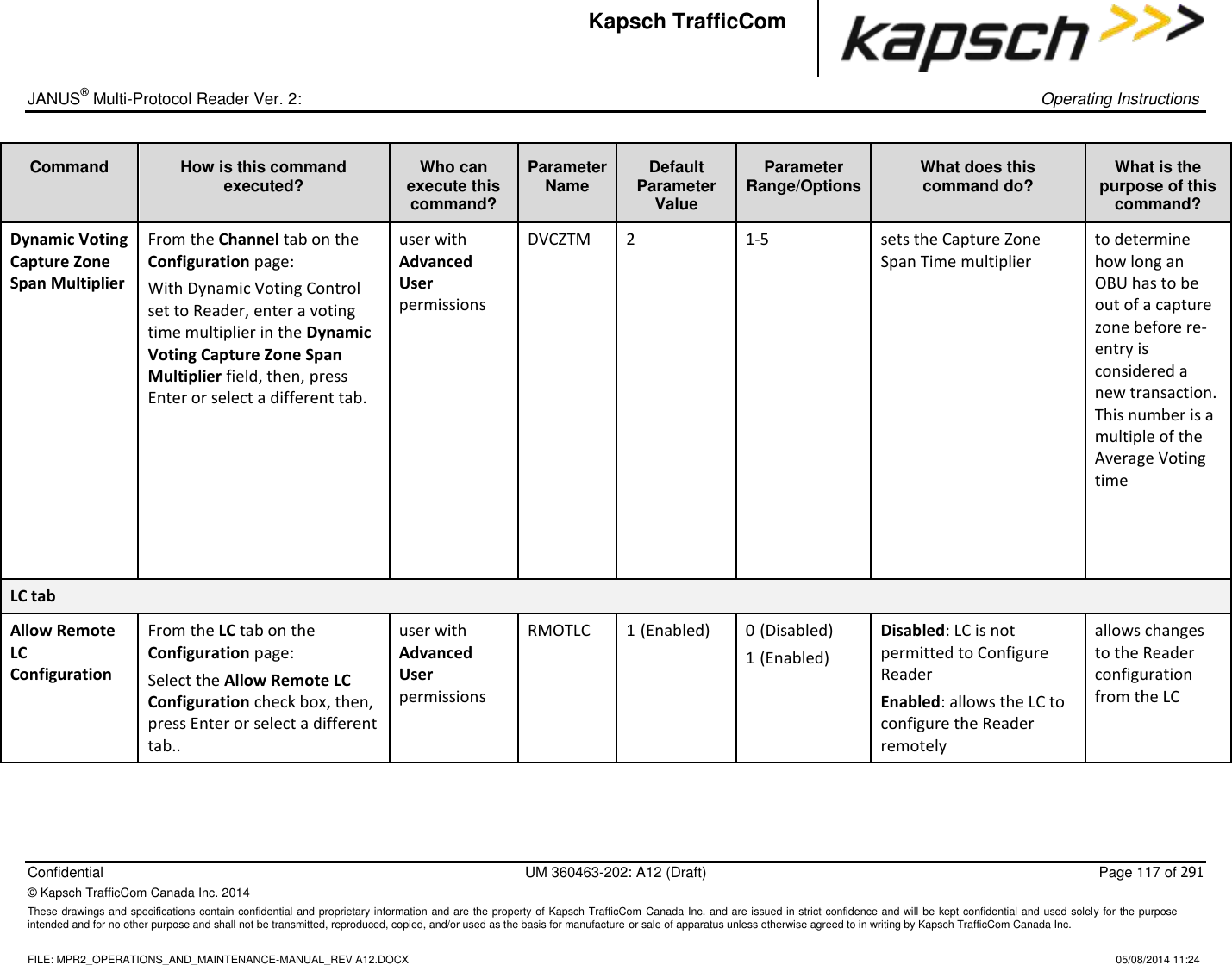
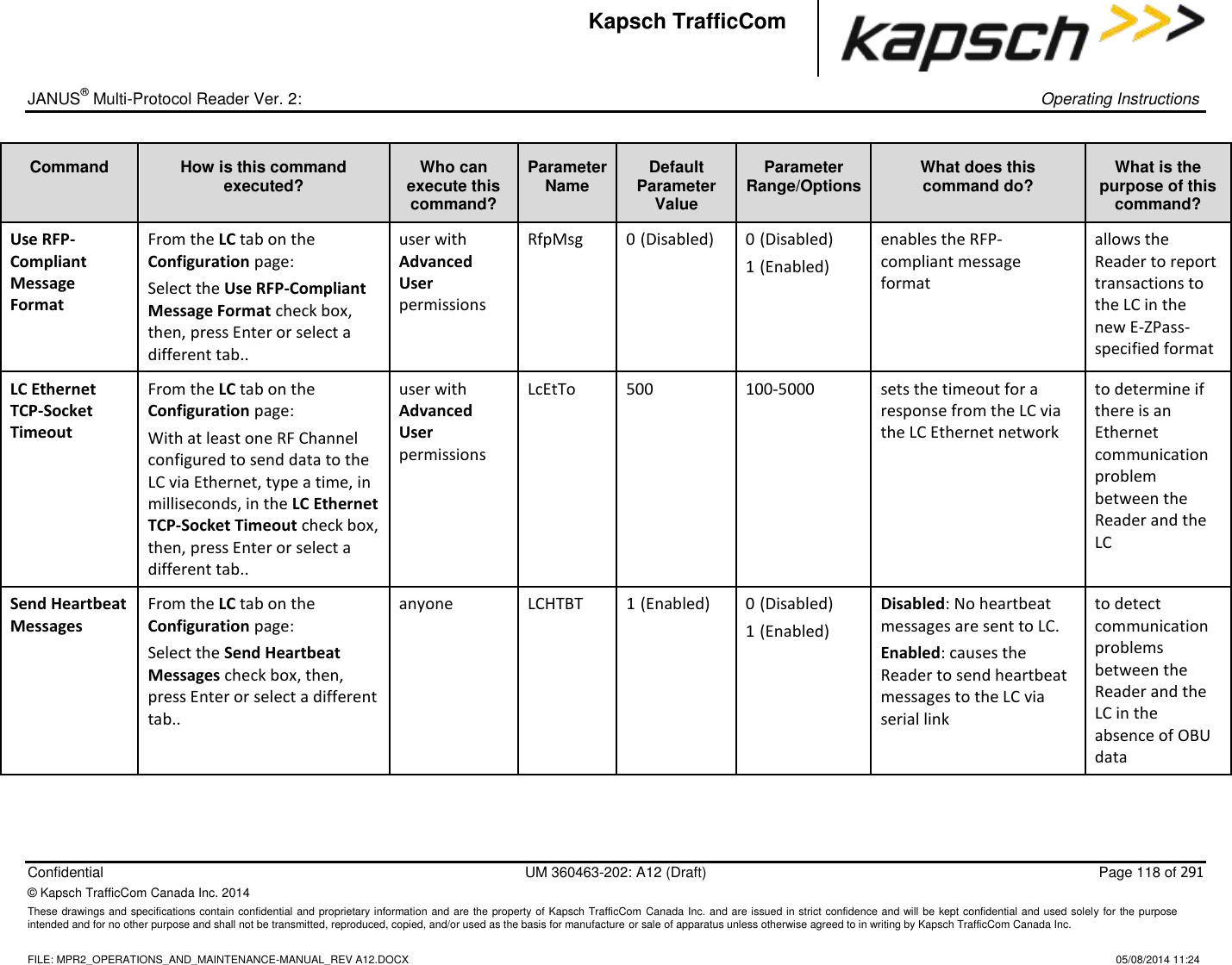
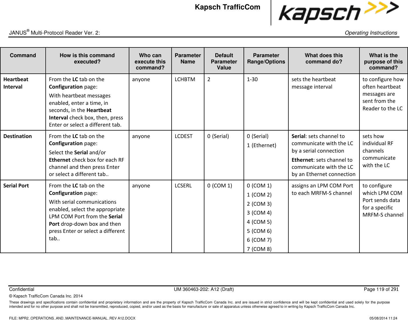
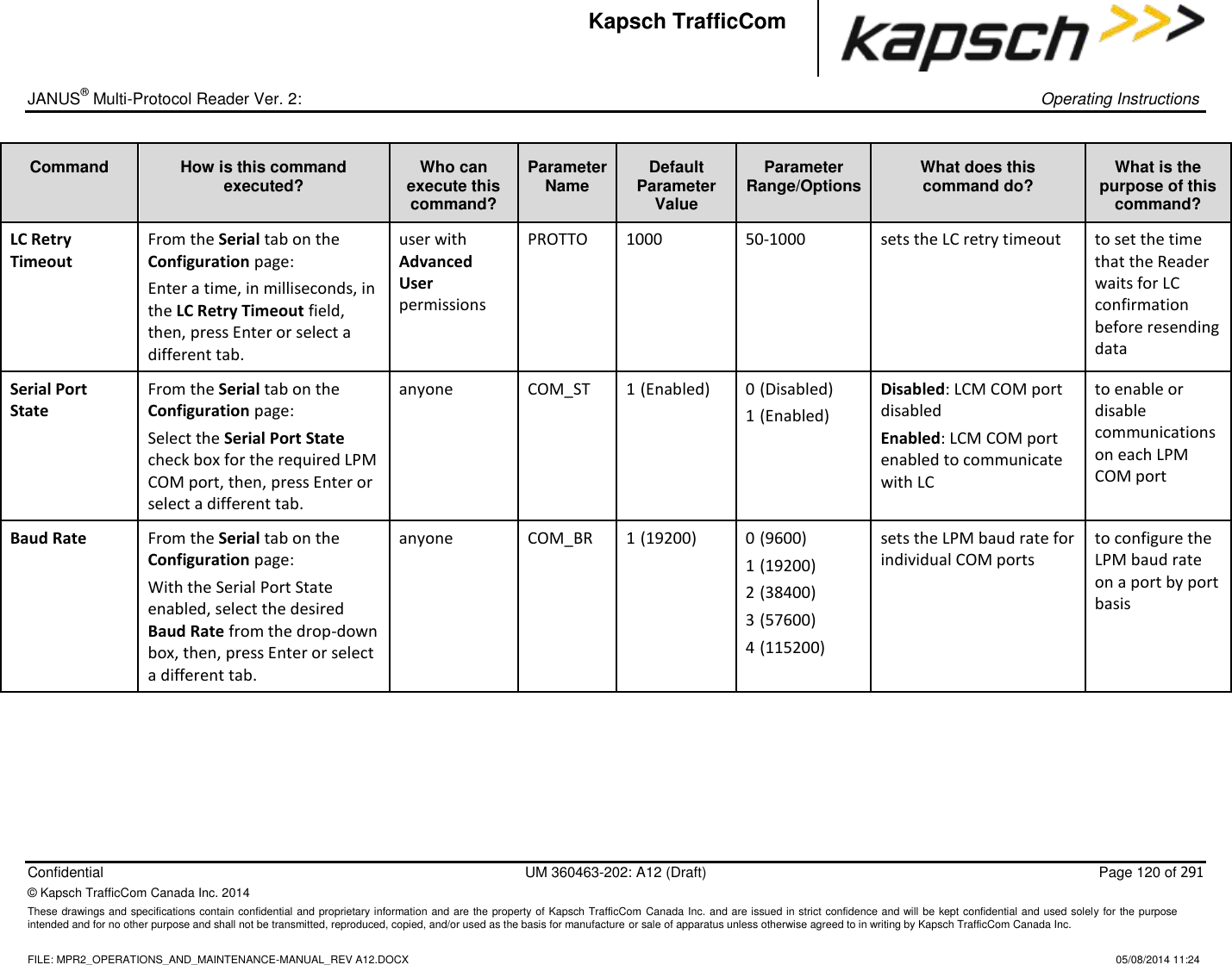
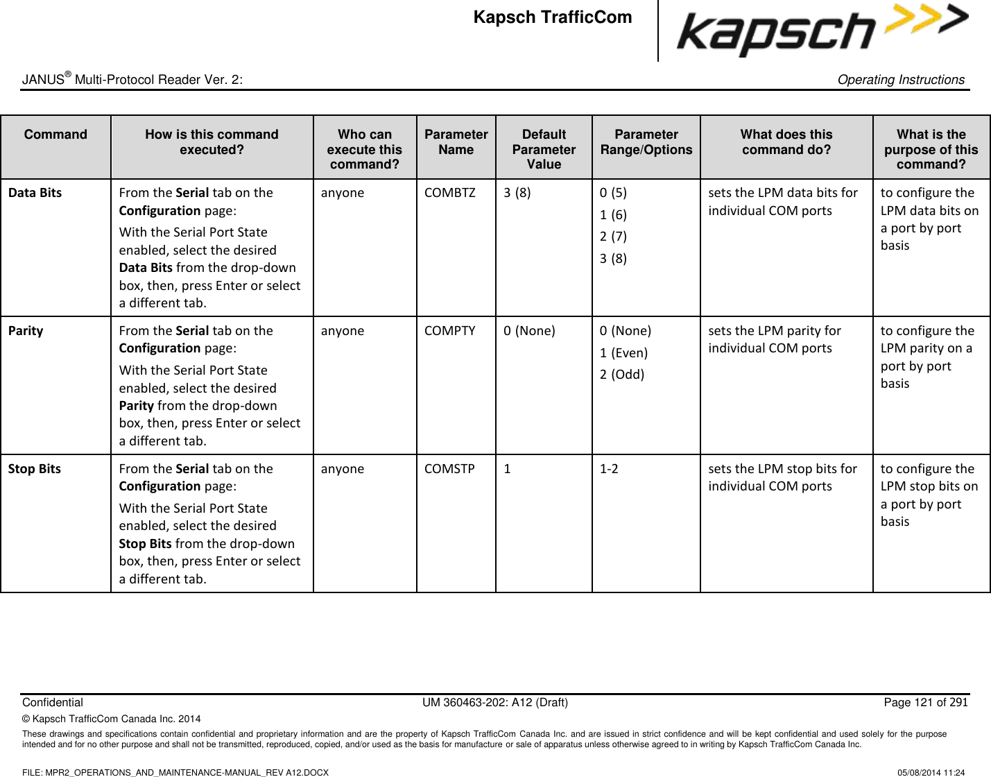
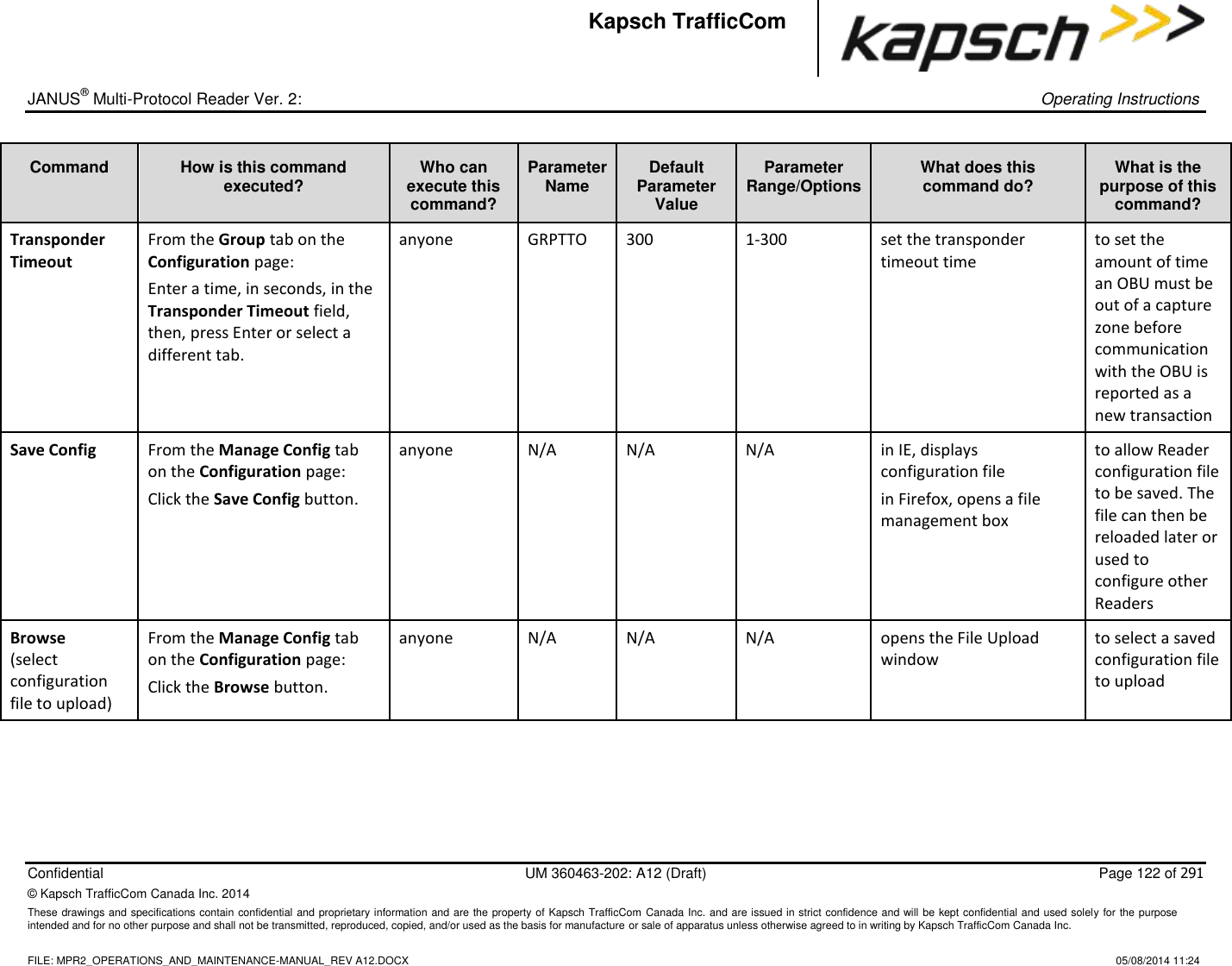
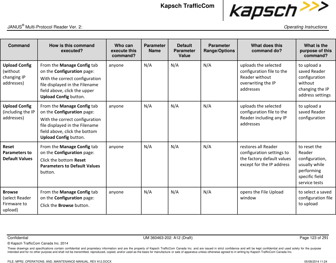
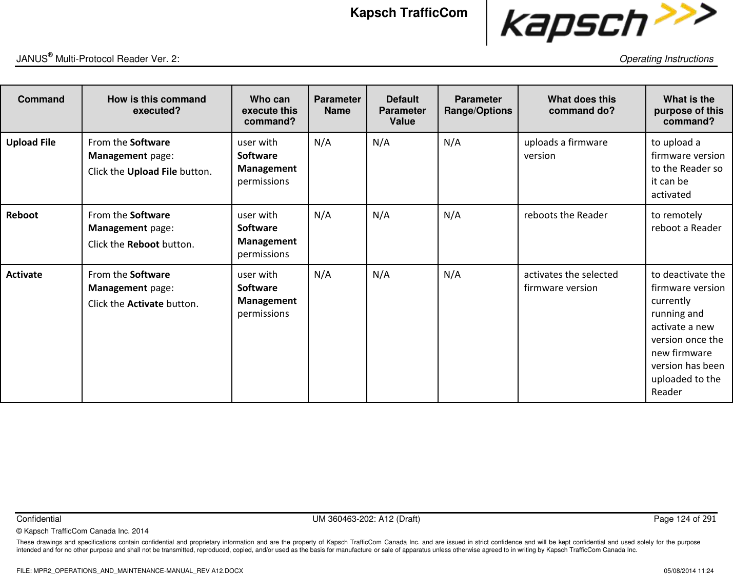
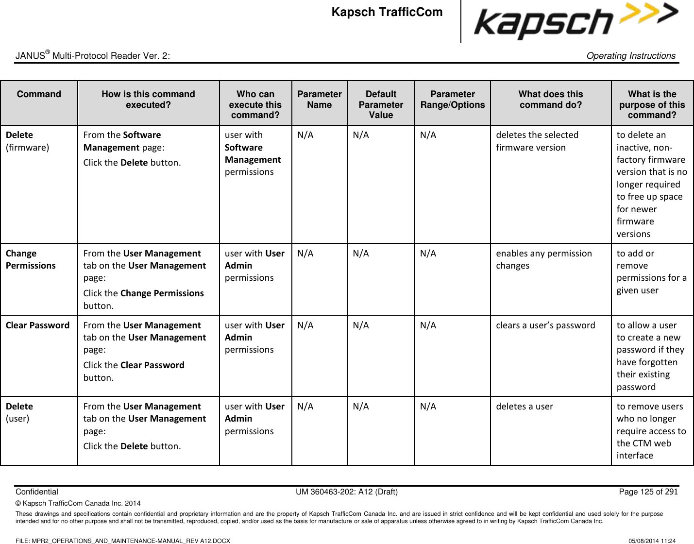
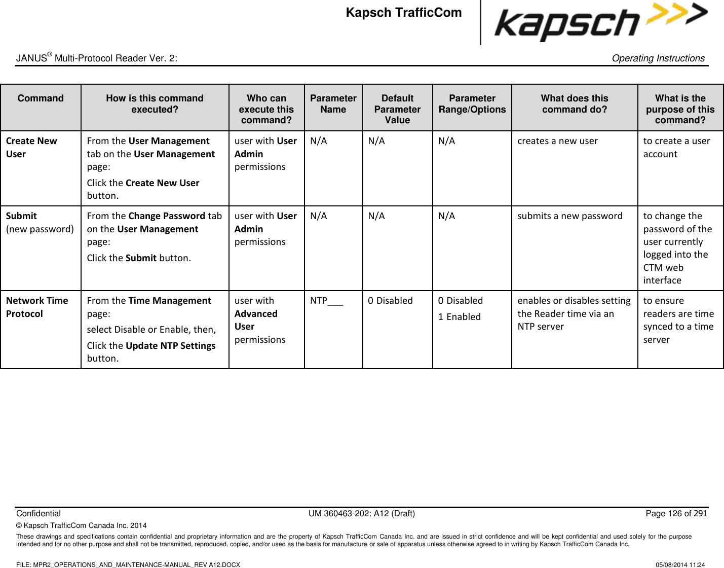
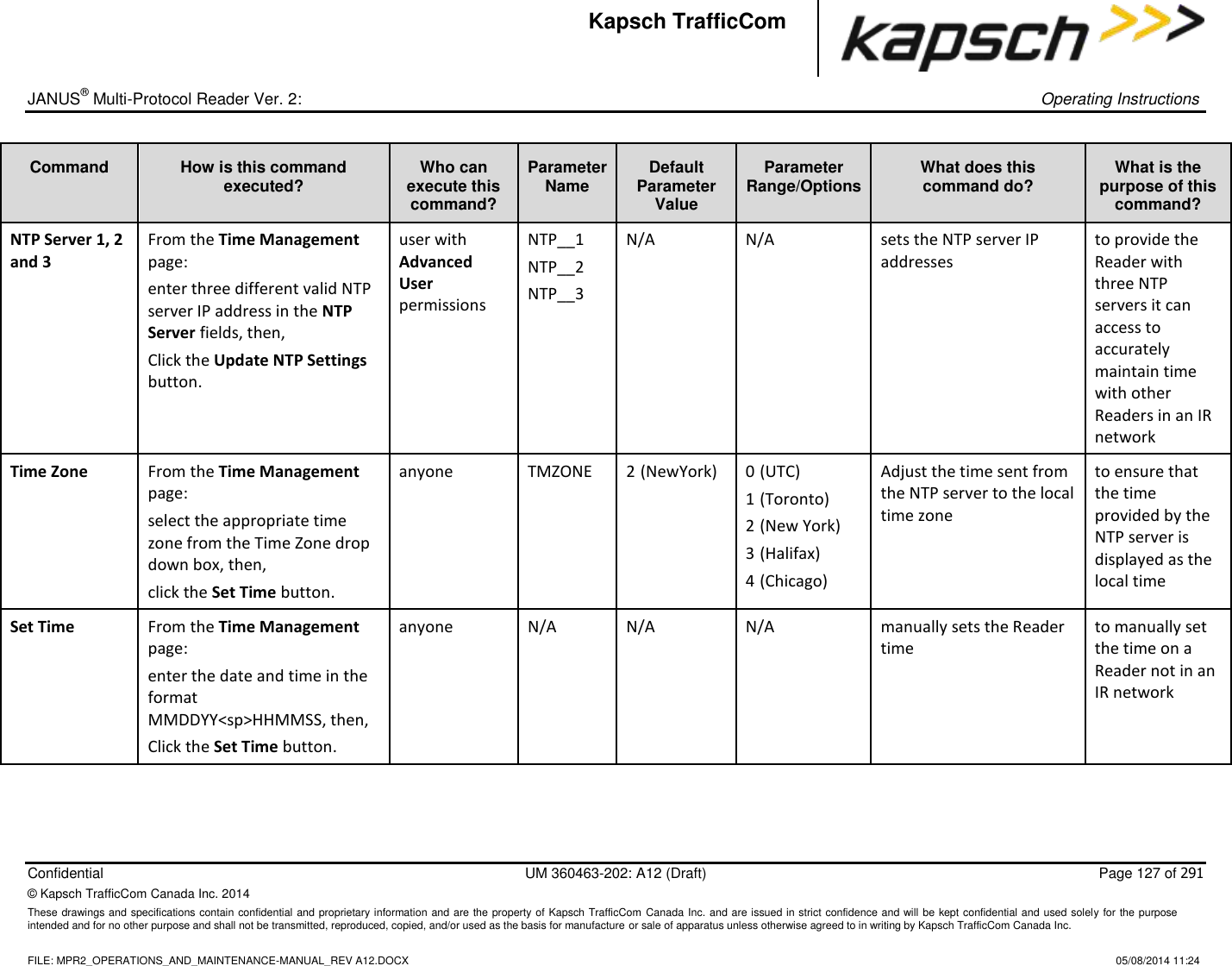
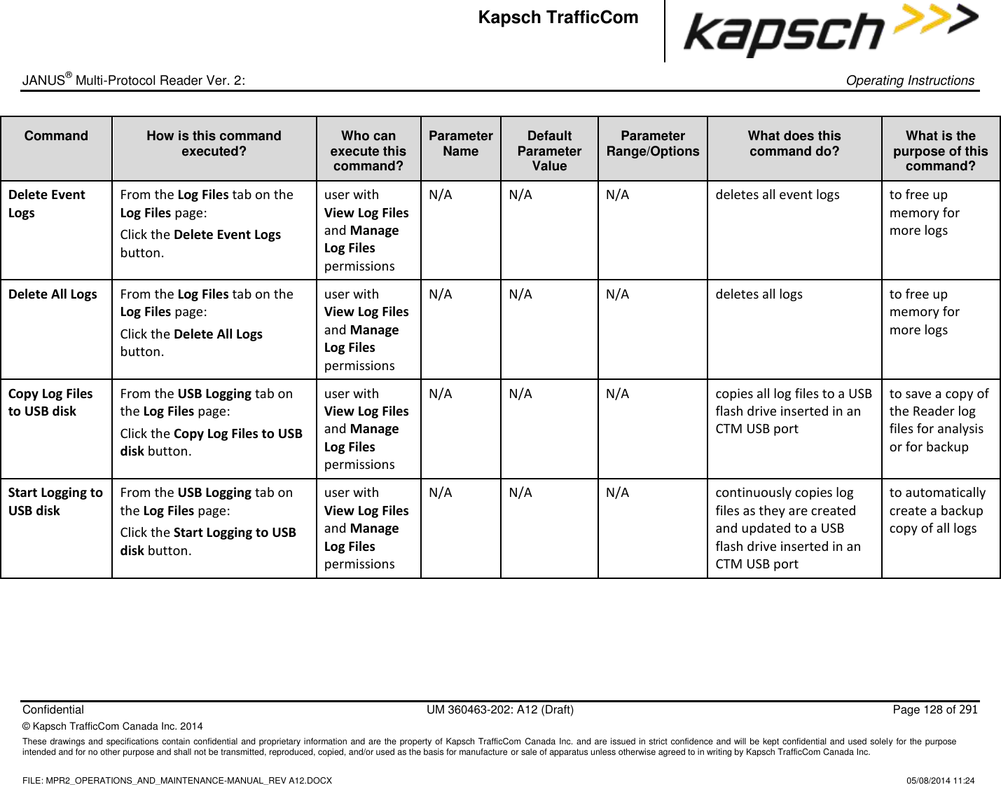
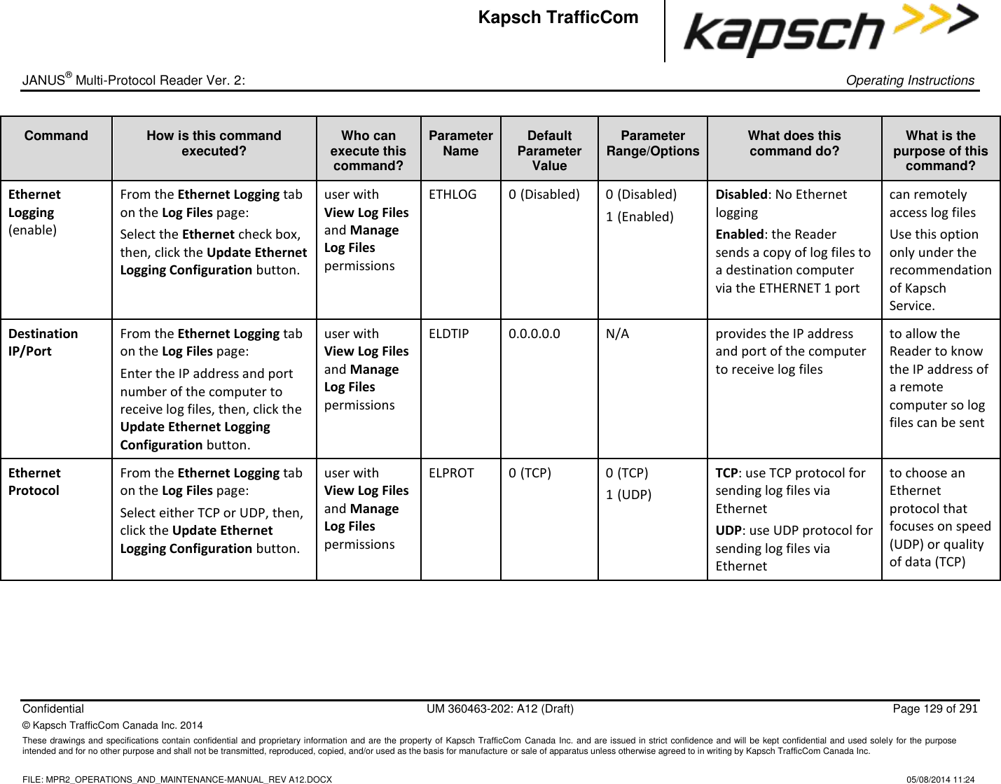
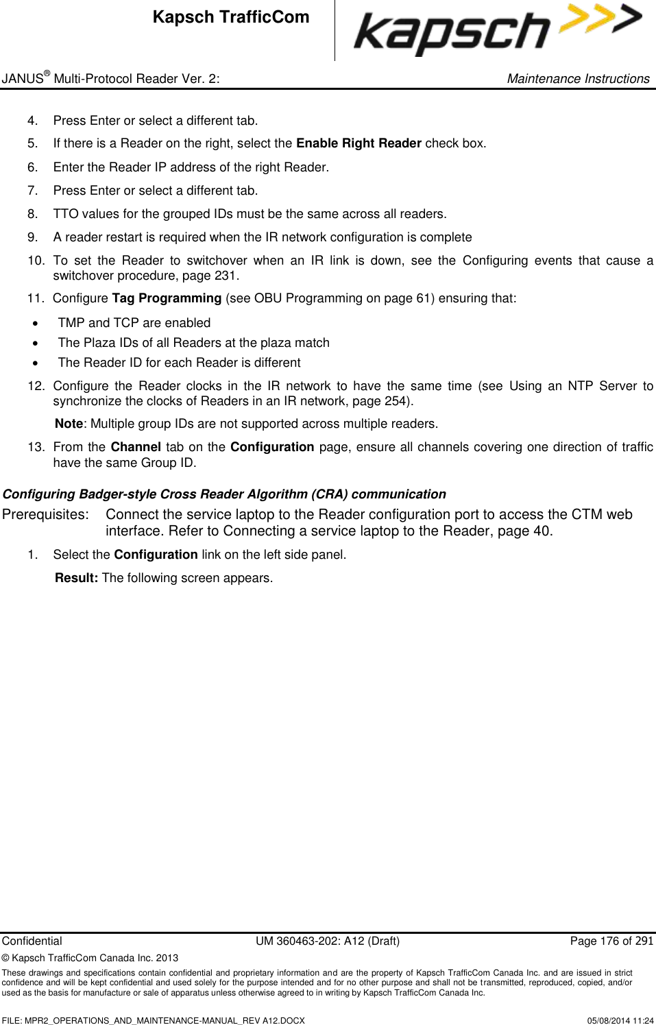
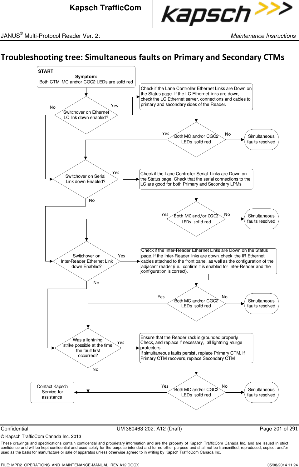
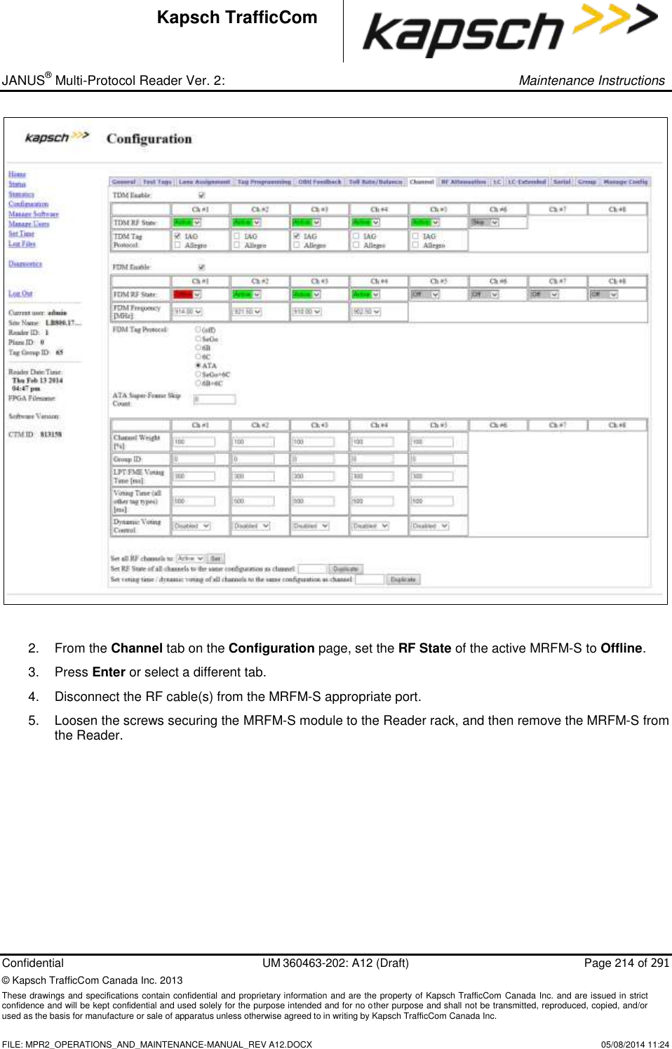
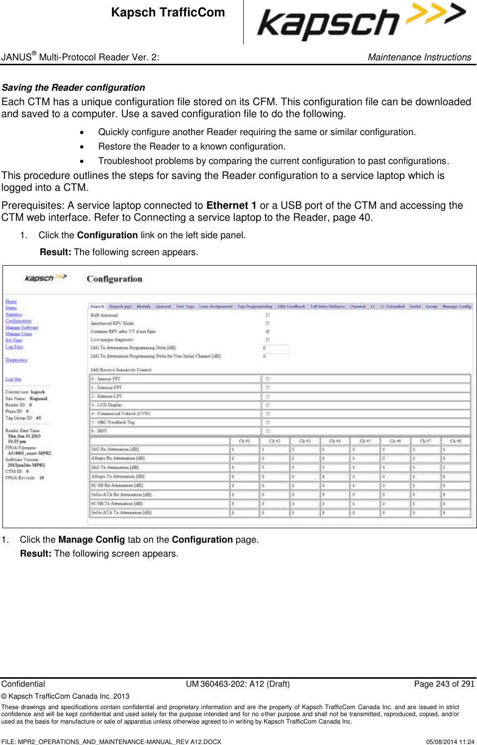
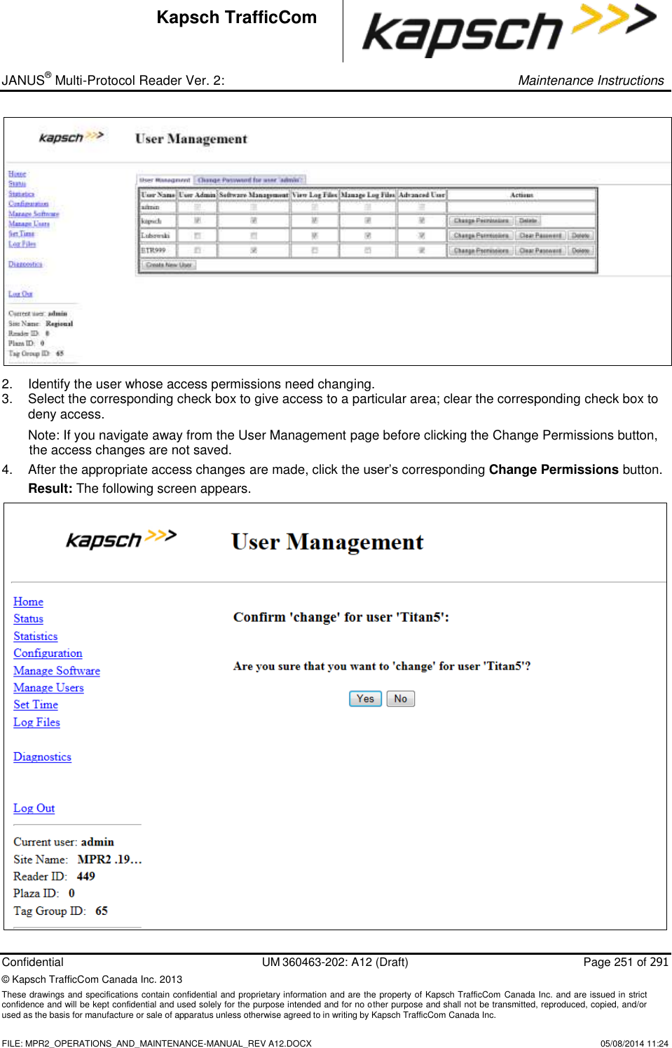
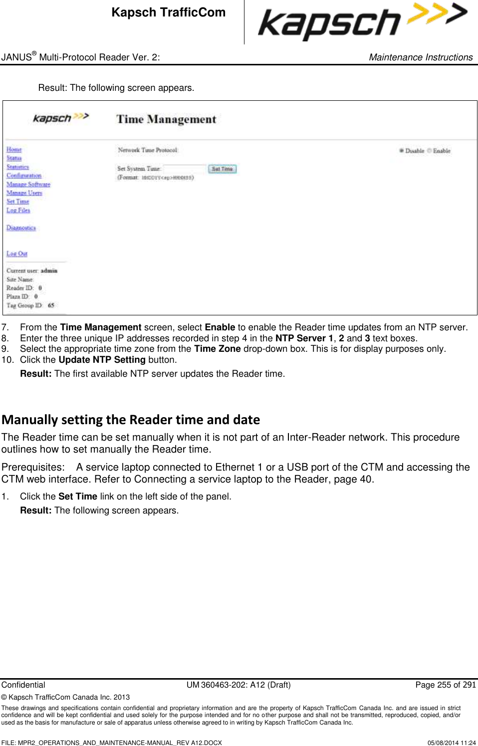
![_ JANUS® Multi-Protocol Reader Ver. 2: Operating Instructions Confidential UM 360463-202: A12 (Draft) Page 82 of 291 © Kapsch TrafficCom Canada Inc. 2014 These drawings and specifications contain confidential and proprietary information and are the property of Kapsch TrafficCom Canada Inc. and are issued in strict confidence and will be kept confidential and used solely for the purpose intended and for no other purpose and shall not be transmitted, reproduced, copied, and/or used as the basis for manufacture or sale of apparatus unless otherwise agreed to in writing by Kapsch TrafficCom Canada Inc. FILE: MPR2_OPERATIONS_AND_MAINTENANCE-MANUAL_REV A12.DOCX 05/08/2014 11:24 Kapsch TrafficCom Command How is this command executed? Who can execute this command? Parameter Name Default Parameter Value Parameter Range/Options What does this command do? What is the purpose of this command? Report Latency by Tag Type: 0 - Interior FPT Delay [ms] From the General tab on the Configuration page: Enter a time (in milliseconds) in the 0- Interior FPT Delay field, then, , click outside the field, press Enter, or select a different tab. user with Advanced User permissions LYCTL0 0 0-5000 sets report delay time in milliseconds for Interior FTP OBUs (Type 0) Used to slow down the transaction report of Type 0 OBUs to the LC for those legacy sites where the LC is expecting BADGER Reader timing 1 - Exterior FPT Delay [ms] From the General tab on the Configuration page: Enter a time (in milliseconds) in the Exterior FPT Delay field, then, , click outside the field, press Enter, or select a different tab. user with Advanced User permissions LYCTL1 0 0-5000 sets report delay time in milliseconds for Exterior FTP OBUs (Type 1). Used to slow down the transaction report of Type 1 OBUs to the LC for those legacy sites where the LC is expecting BADGER Reader timing](https://usermanual.wiki/KAPSCH-TRAFFICCOM-CANADA/802295A.Operations-and-Maintenance-Manual/User-Guide-2263970-Page-82.png)
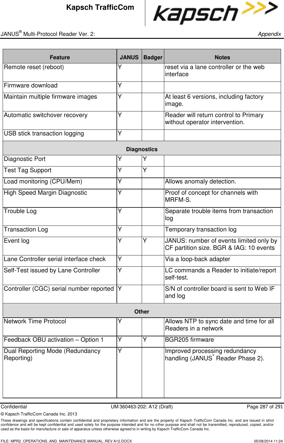
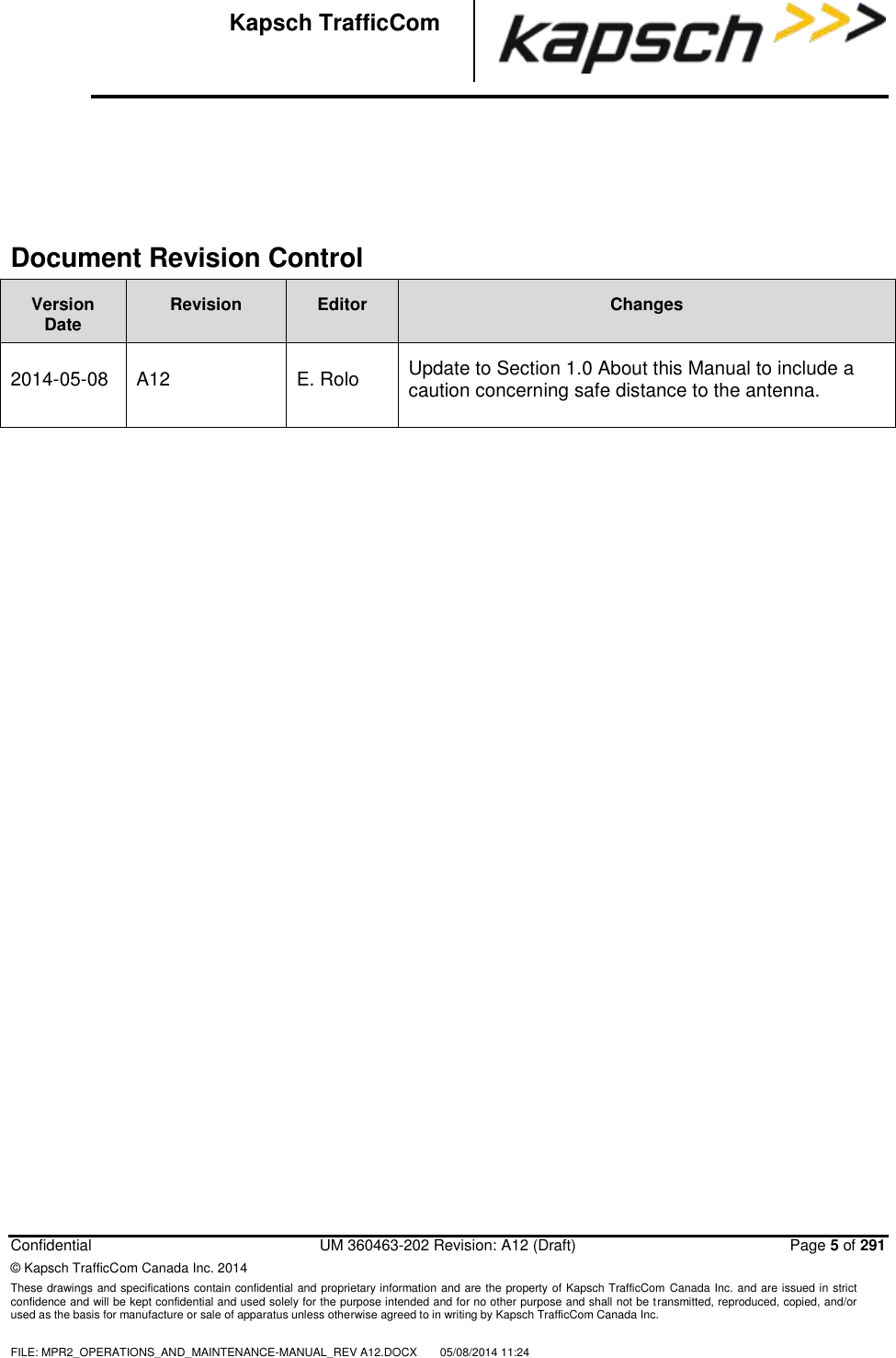
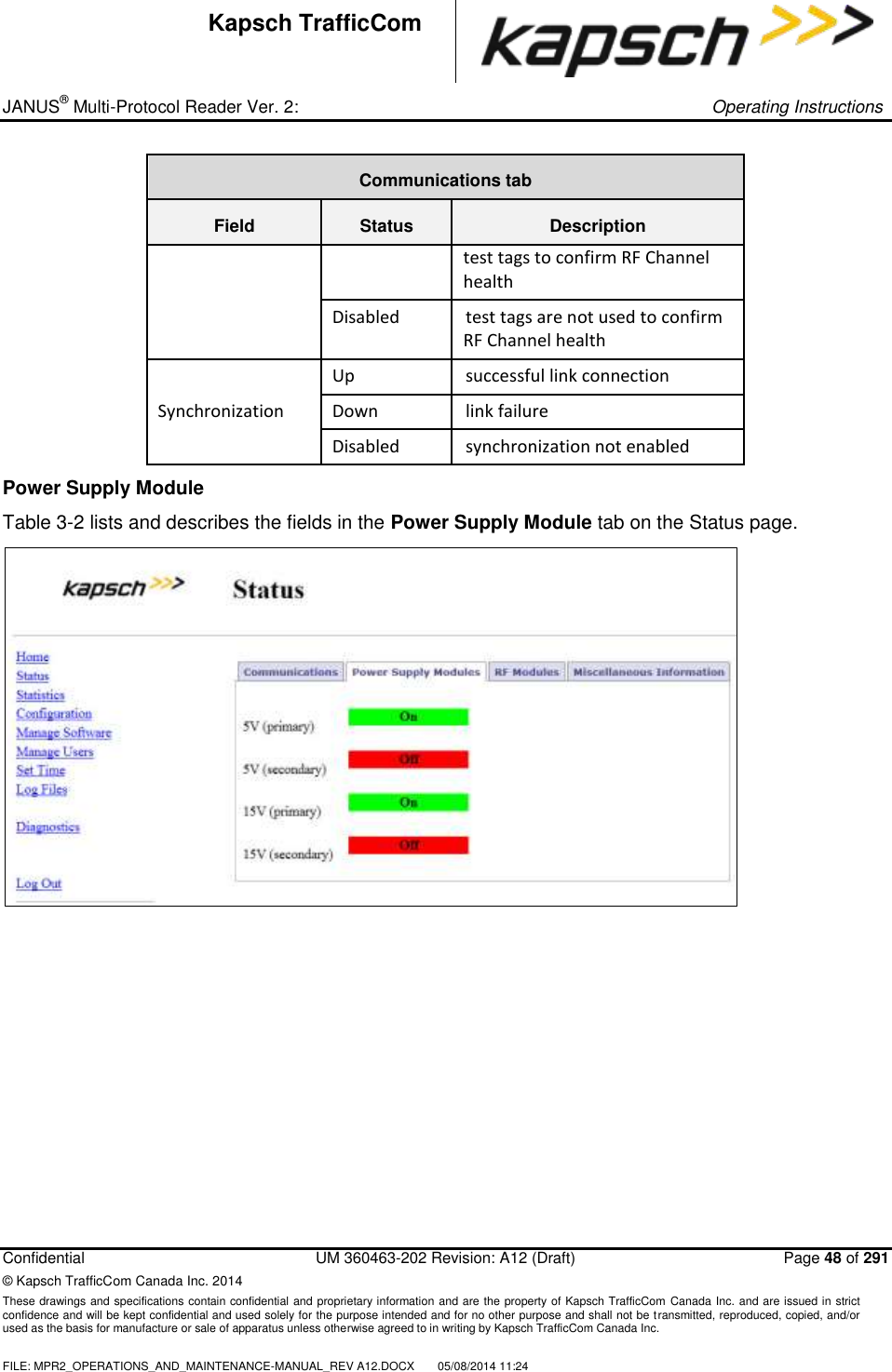
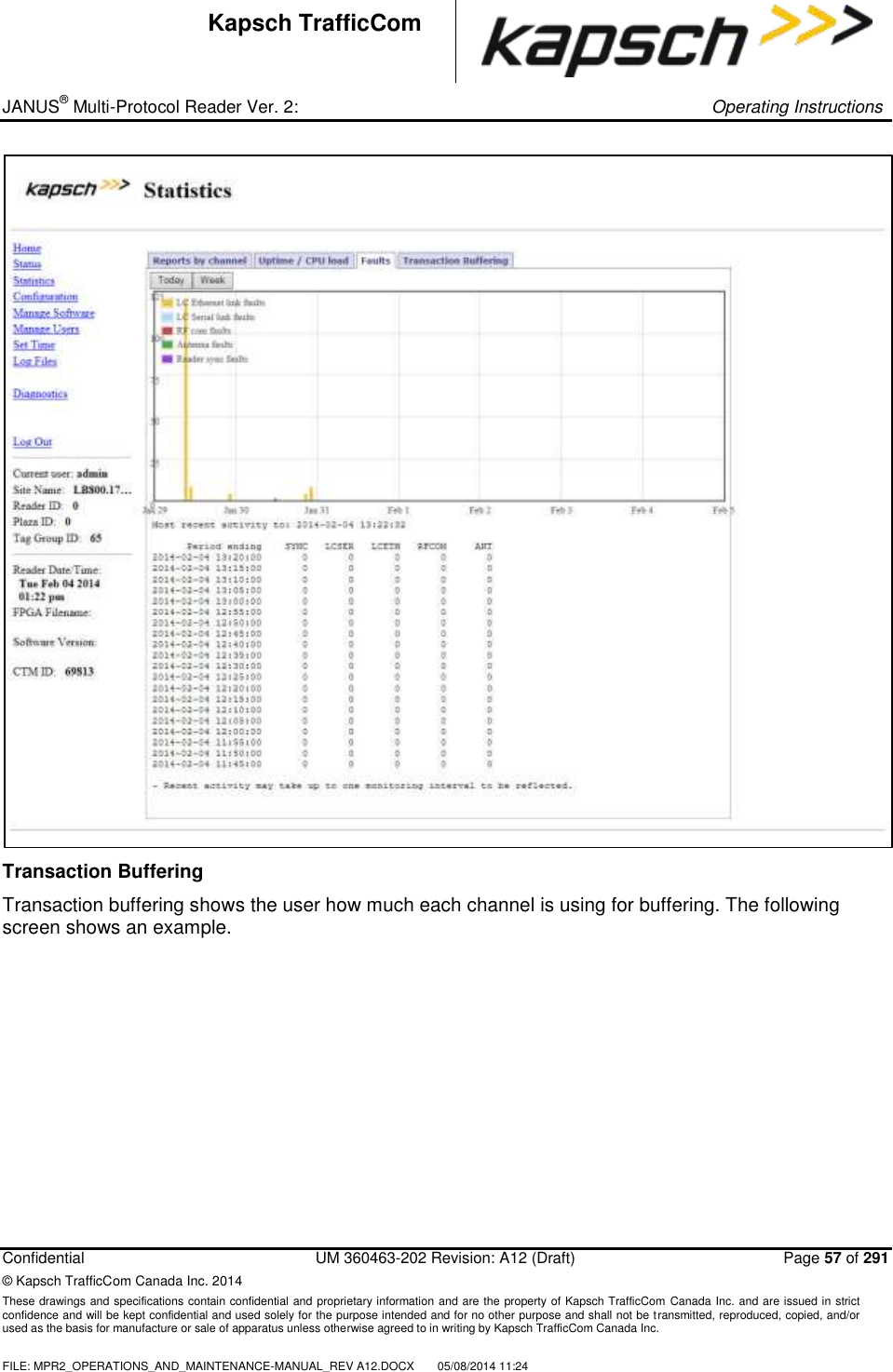
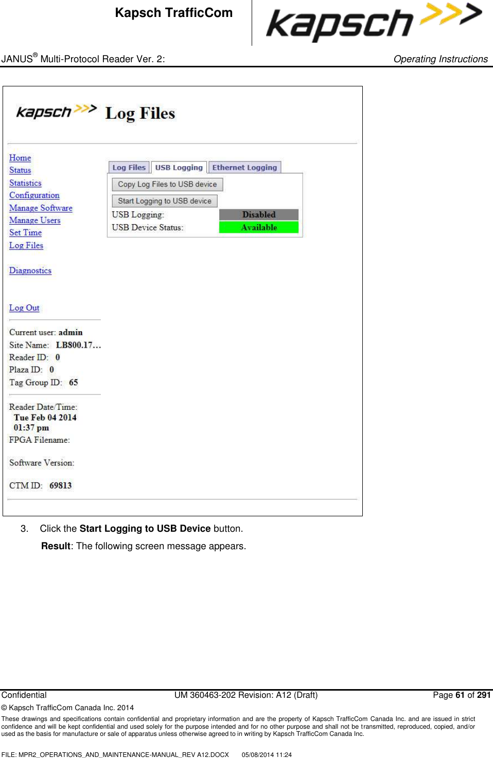
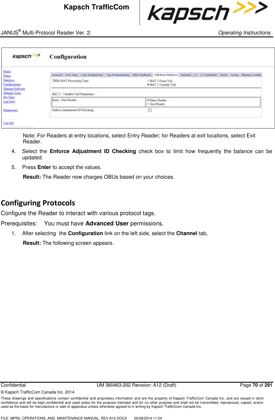
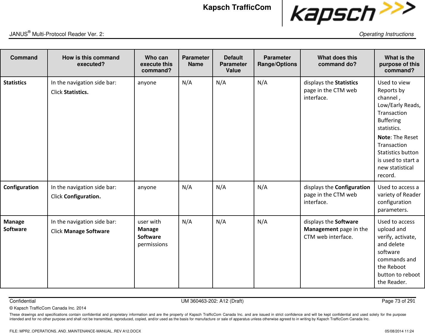
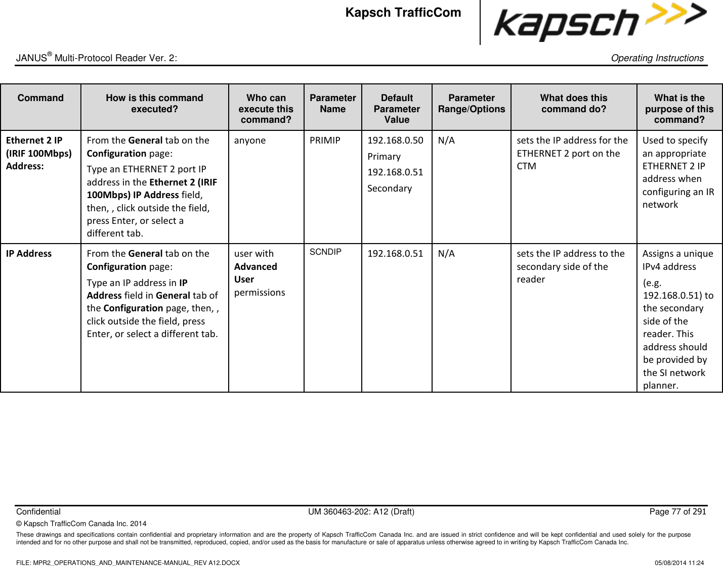
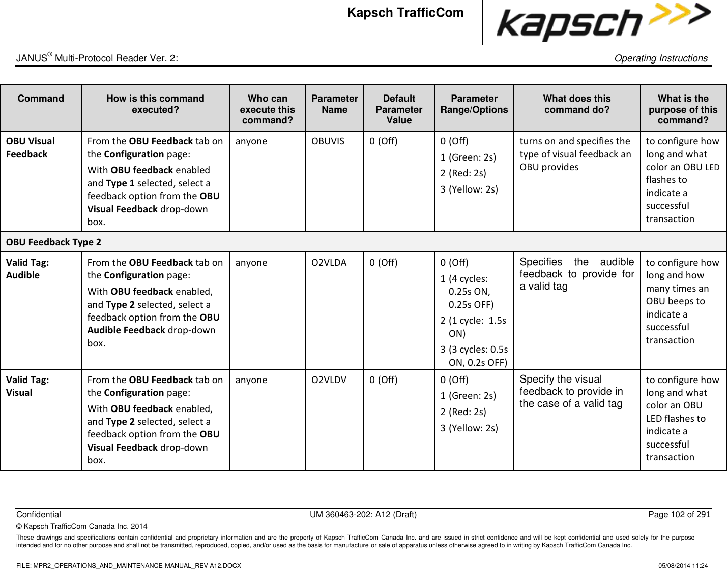
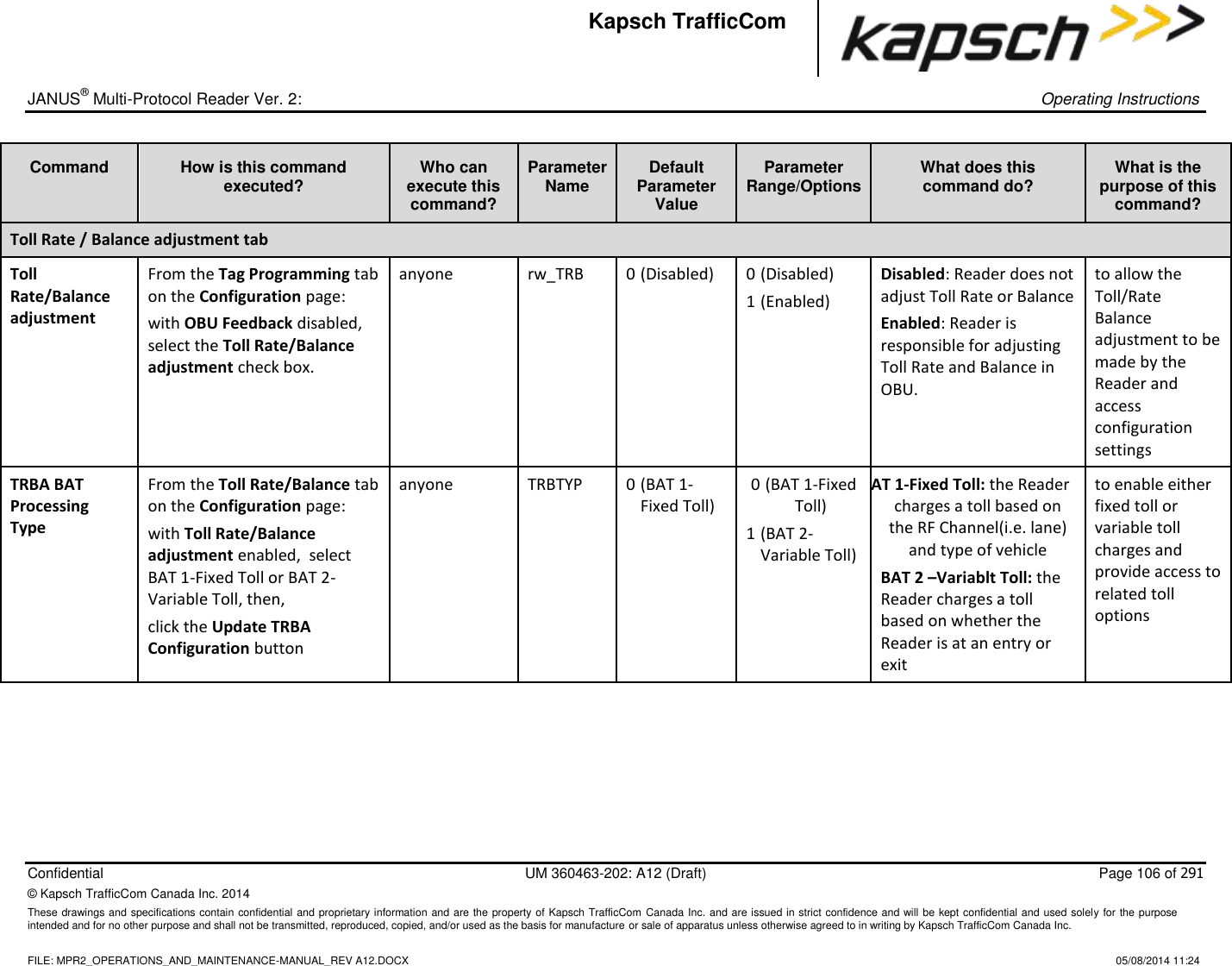
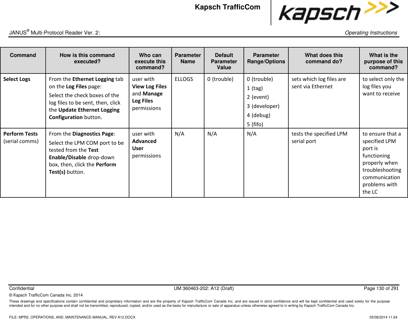
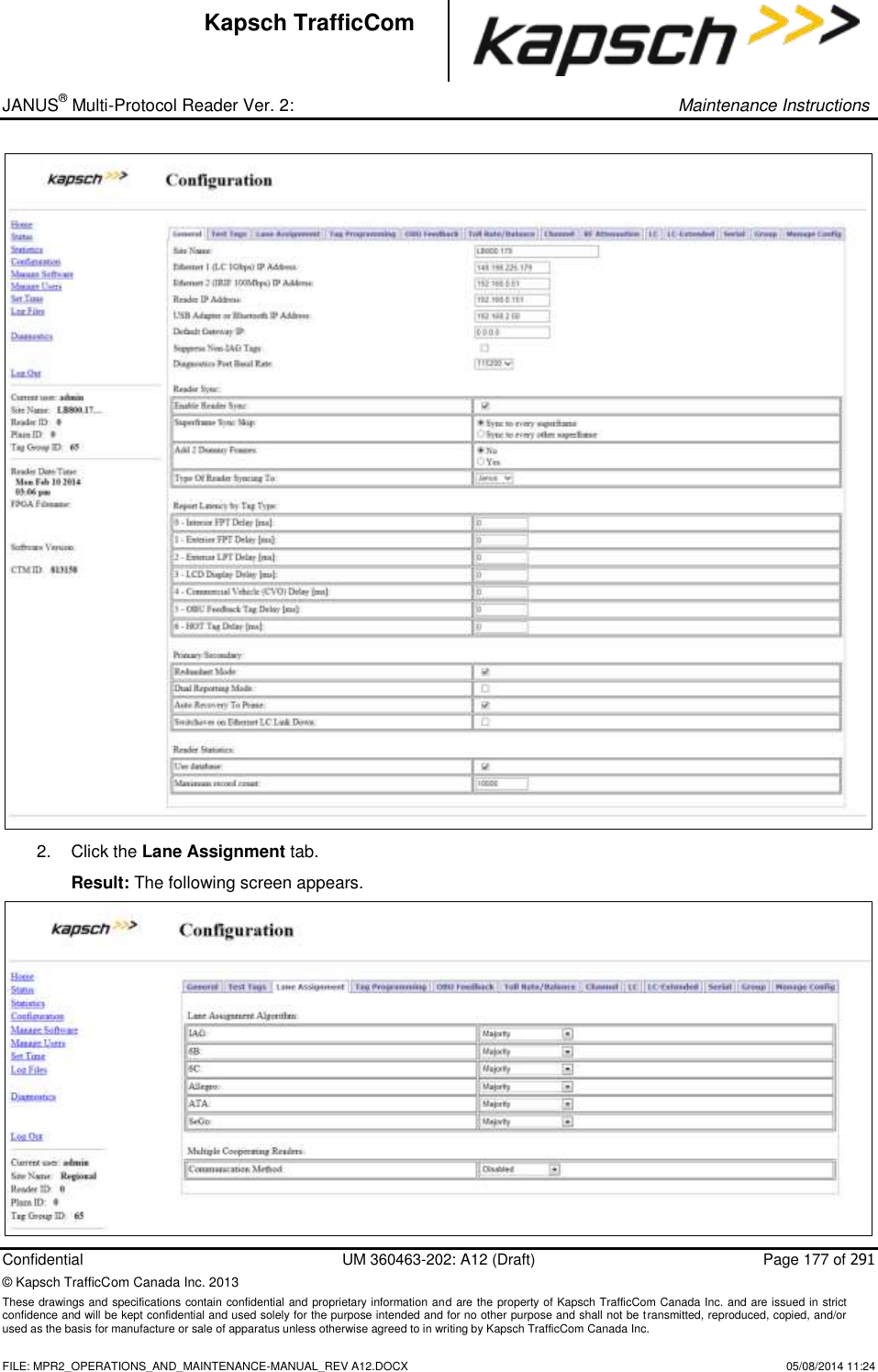
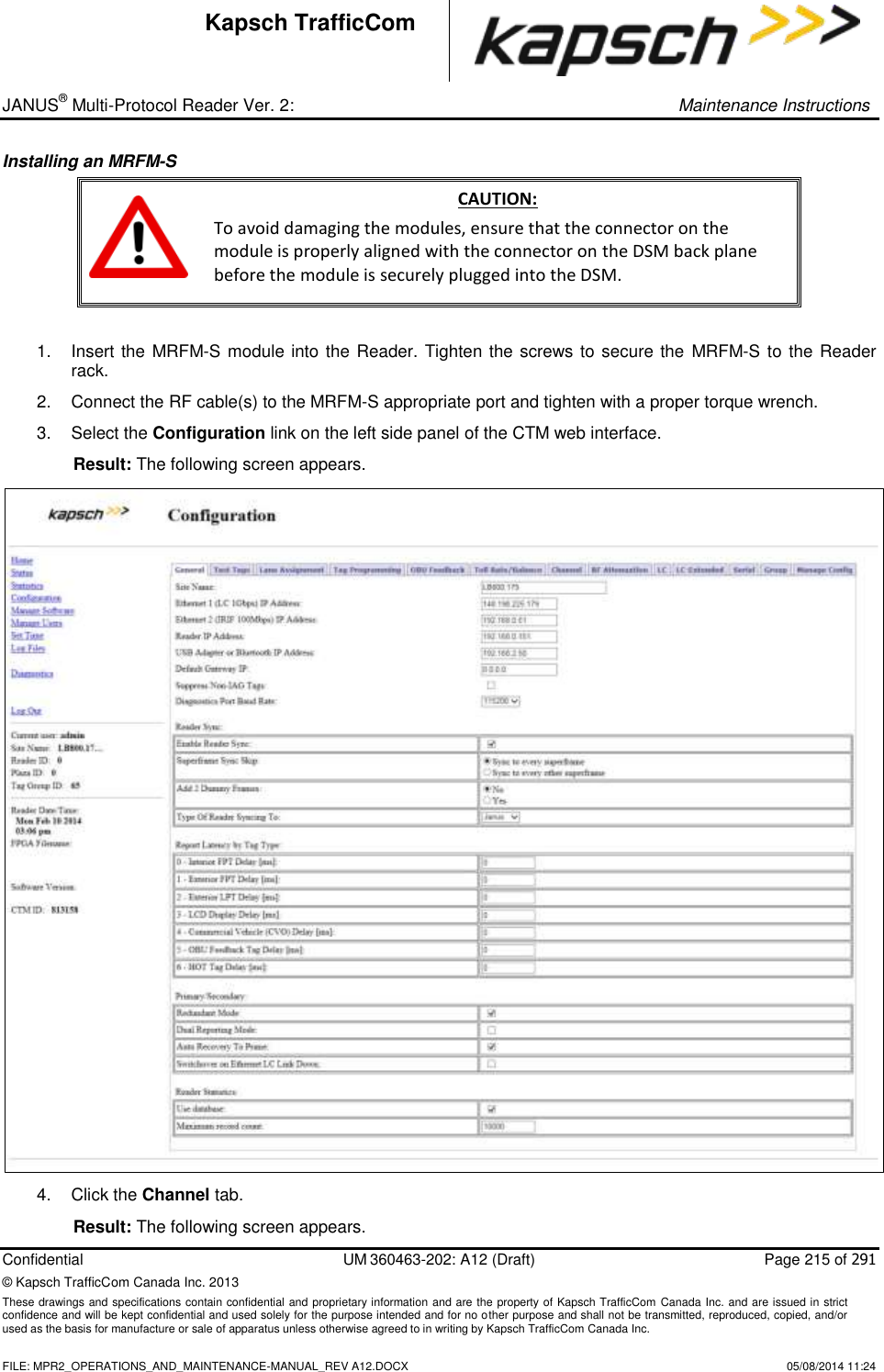
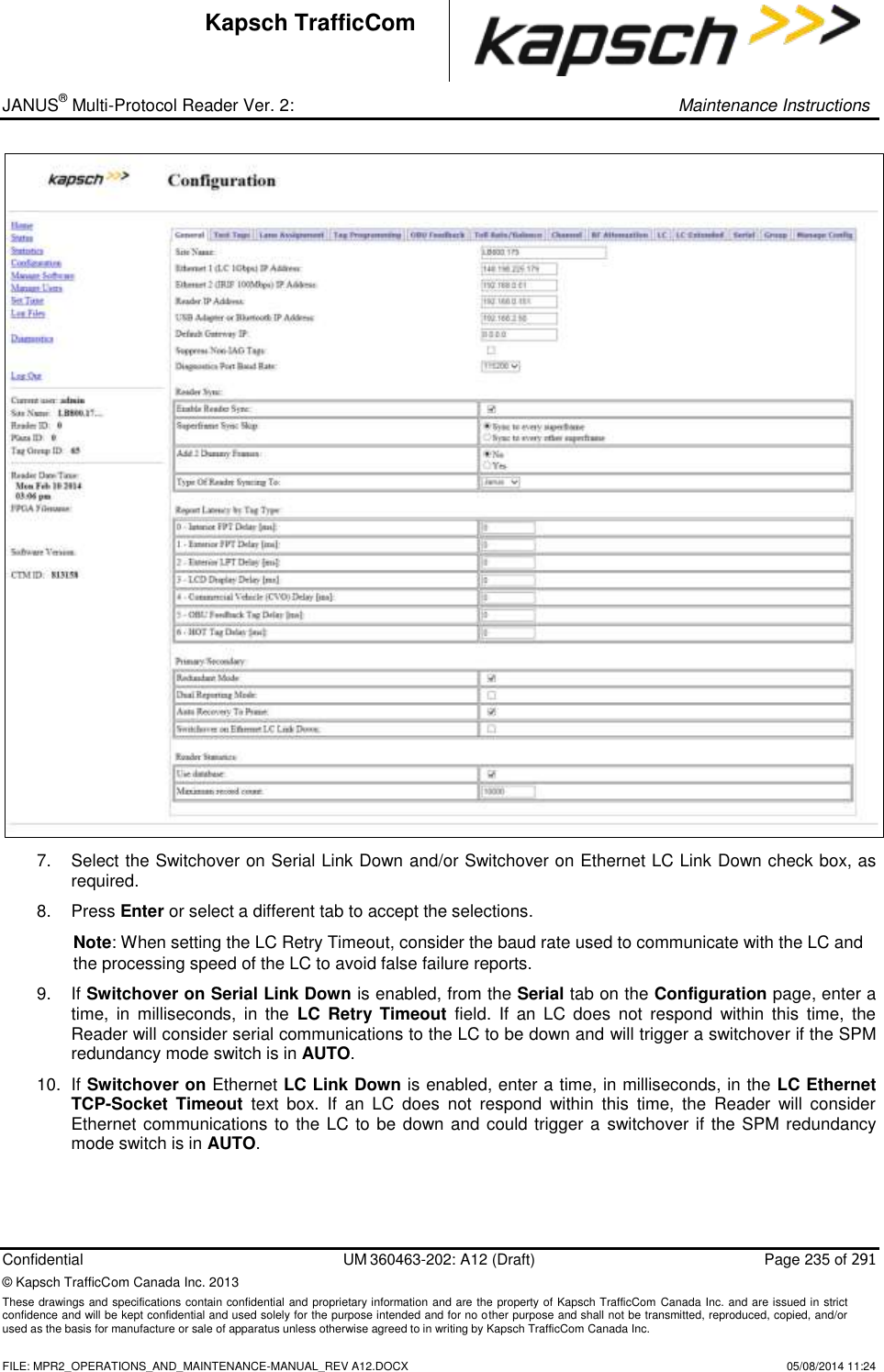
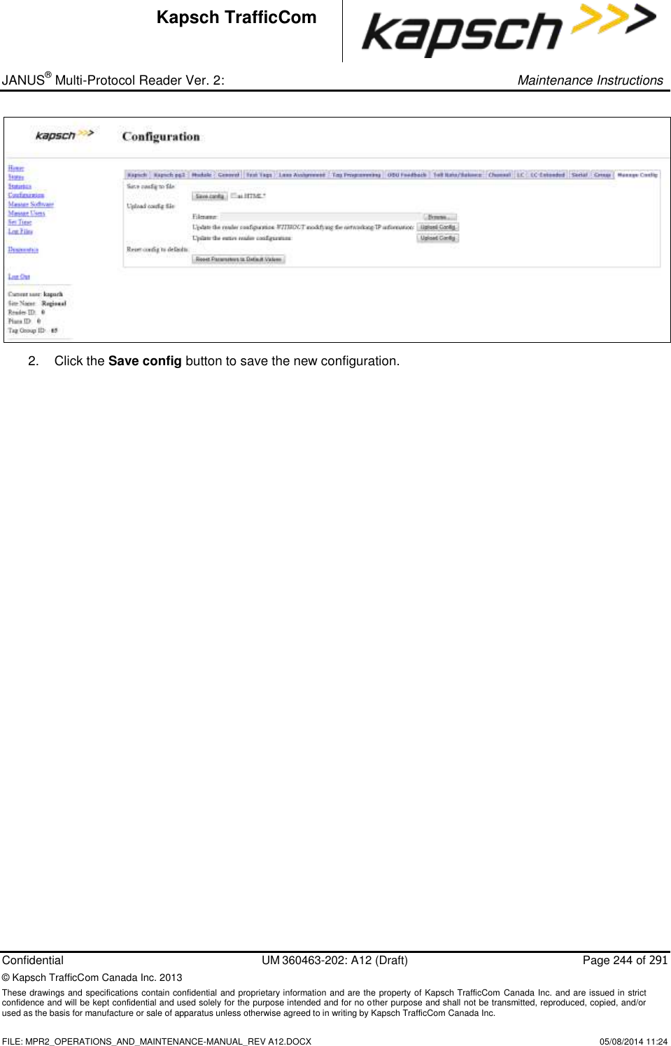
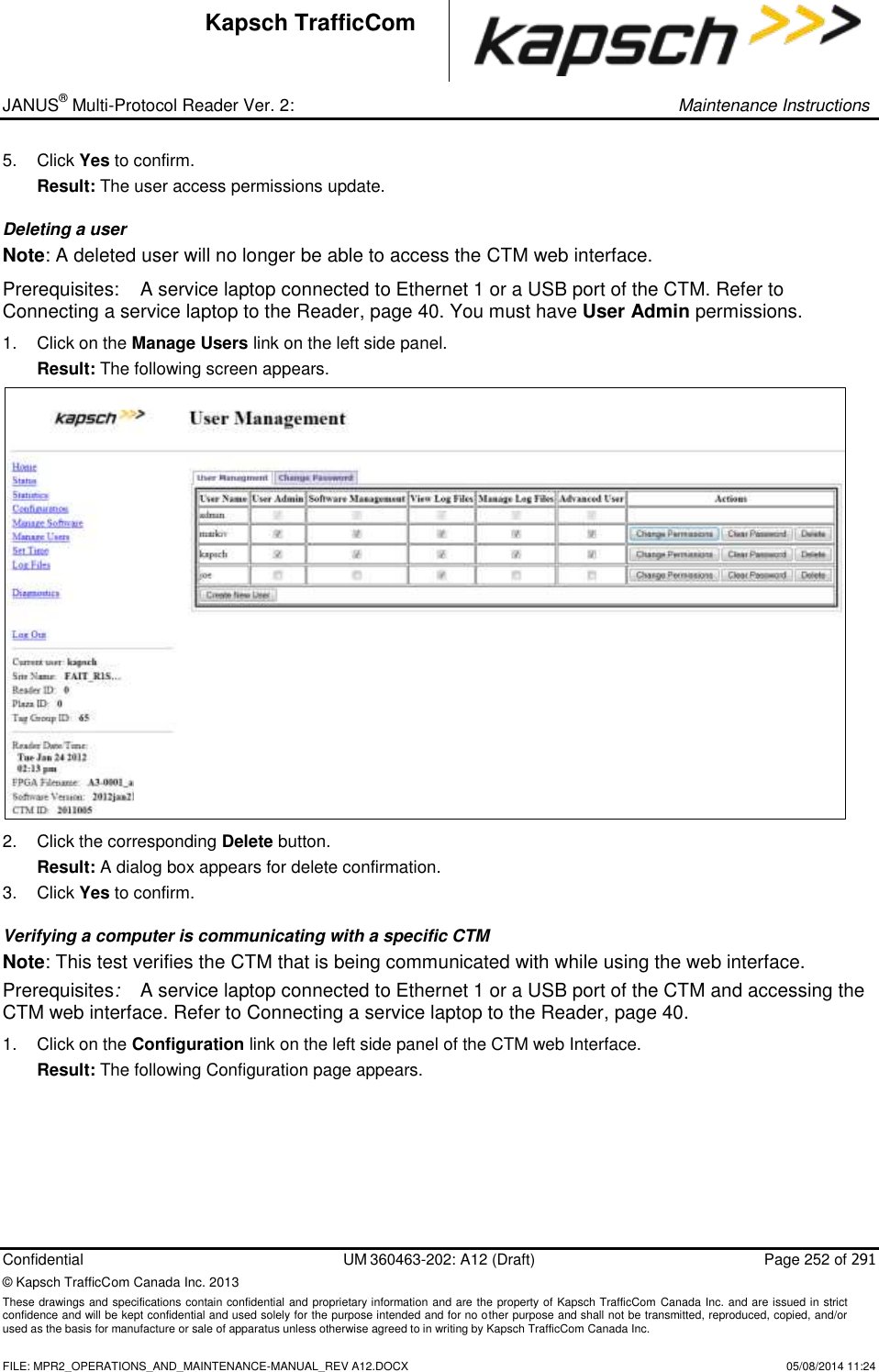
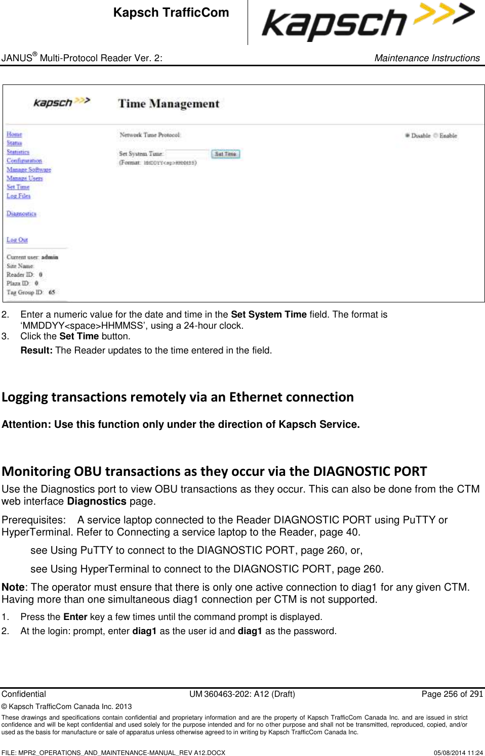
![_ JANUS® Multi-Protocol Reader Ver. 2: Operating Instructions Confidential UM 360463-202: A12 (Draft) Page 83 of 291 © Kapsch TrafficCom Canada Inc. 2014 These drawings and specifications contain confidential and proprietary information and are the property of Kapsch TrafficCom Canada Inc. and are issued in strict confidence and will be kept confidential and used solely for the purpose intended and for no other purpose and shall not be transmitted, reproduced, copied, and/or used as the basis for manufacture or sale of apparatus unless otherwise agreed to in writing by Kapsch TrafficCom Canada Inc. FILE: MPR2_OPERATIONS_AND_MAINTENANCE-MANUAL_REV A12.DOCX 05/08/2014 11:24 Kapsch TrafficCom Command How is this command executed? Who can execute this command? Parameter Name Default Parameter Value Parameter Range/Options What does this command do? What is the purpose of this command? 2 - Exterior LPT Delay [ms] From the General tab on the Configuration page: Enter a time (in milliseconds) in the Exterior LPT Delay field, then, , click outside the field, press Enter, or select a different tab. user with Advanced User permissions LYCTL2 0 0-5000 sets report delay time in milliseconds for Exterior LPT OBUs (Type 2). Used to slow down the transaction report of Type 2 OBUs to the LC for those legacy sites where the LC is expecting BADGER Reader timing 3 - LCD Display Delay [ms] From the General tab on the Configuration page: Enter a time (in milliseconds) in the LCD Display Delay field, then, , click outside the field, press Enter, or select a different tab. user with Advanced User permissions LYCTL3 0 0-5000 sets report delay time in milliseconds for LCD Display OBUs (Type 3). Used to slow down the transaction report of Type 3 OBUs to the LC for those legacy sites where the LC is expecting BADGER Reader timing](https://usermanual.wiki/KAPSCH-TRAFFICCOM-CANADA/802295A.Operations-and-Maintenance-Manual/User-Guide-2263970-Page-83.png)
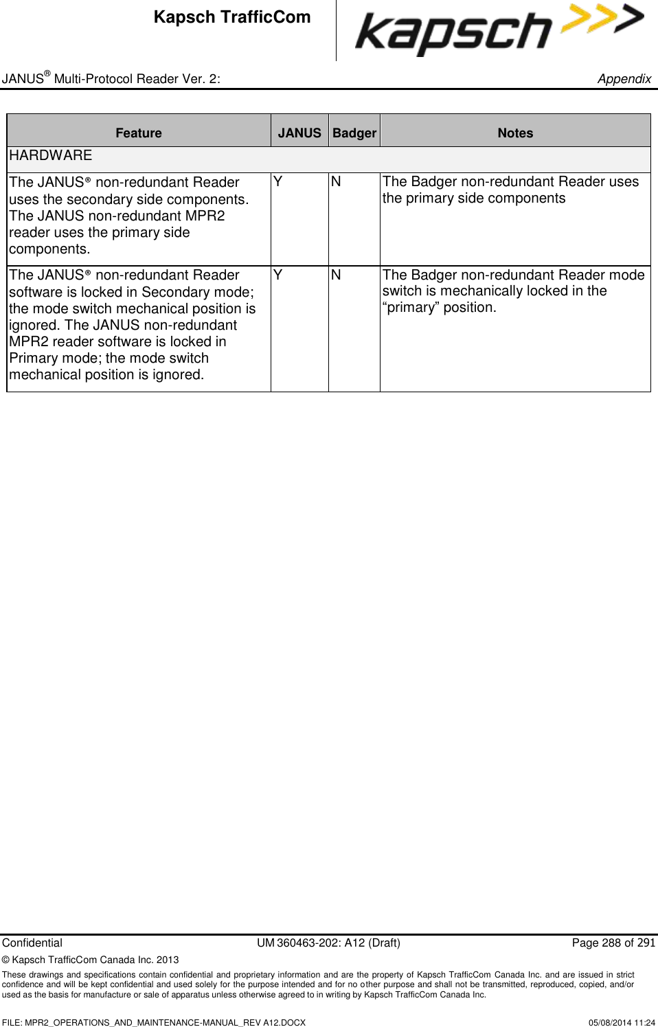
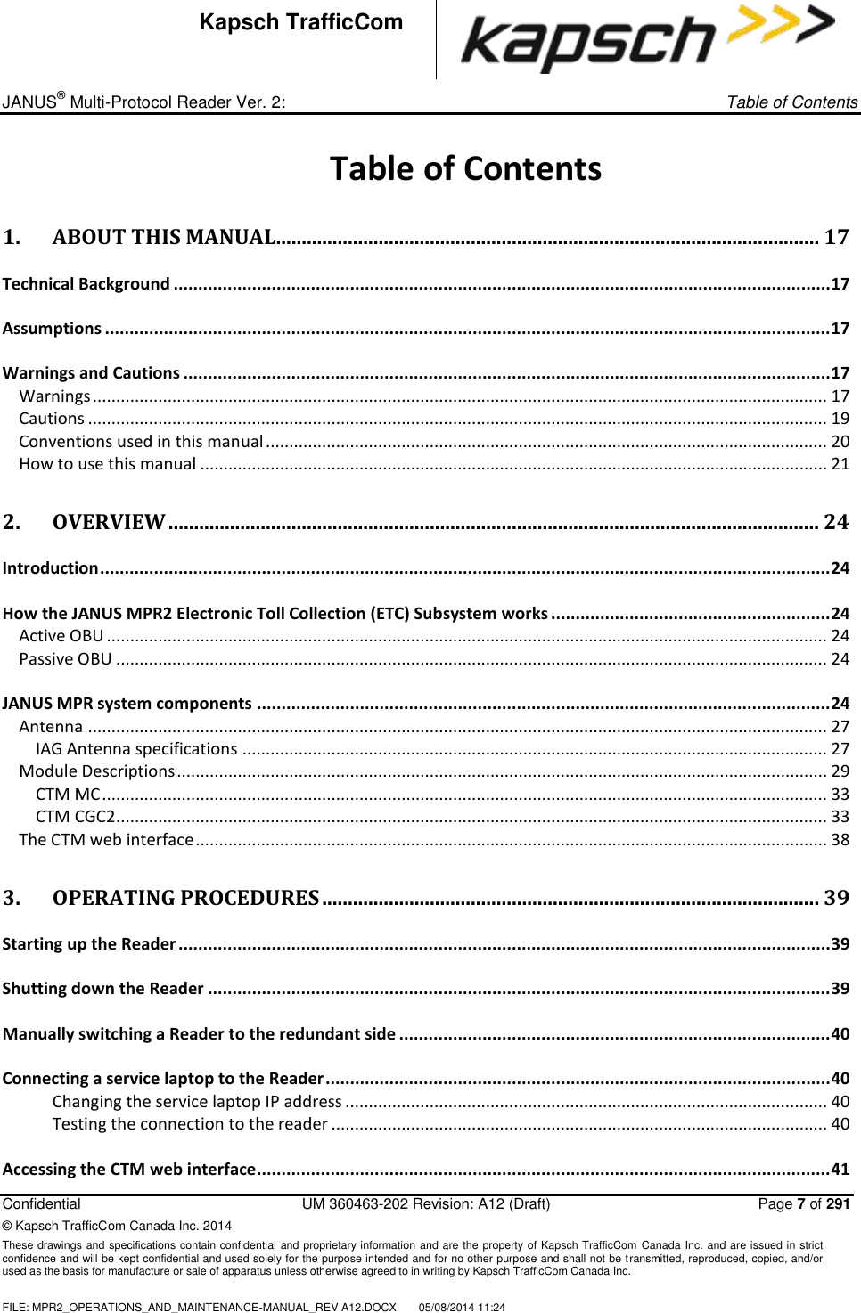
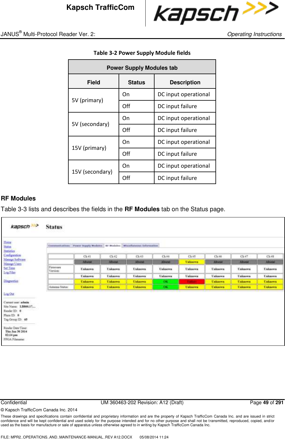
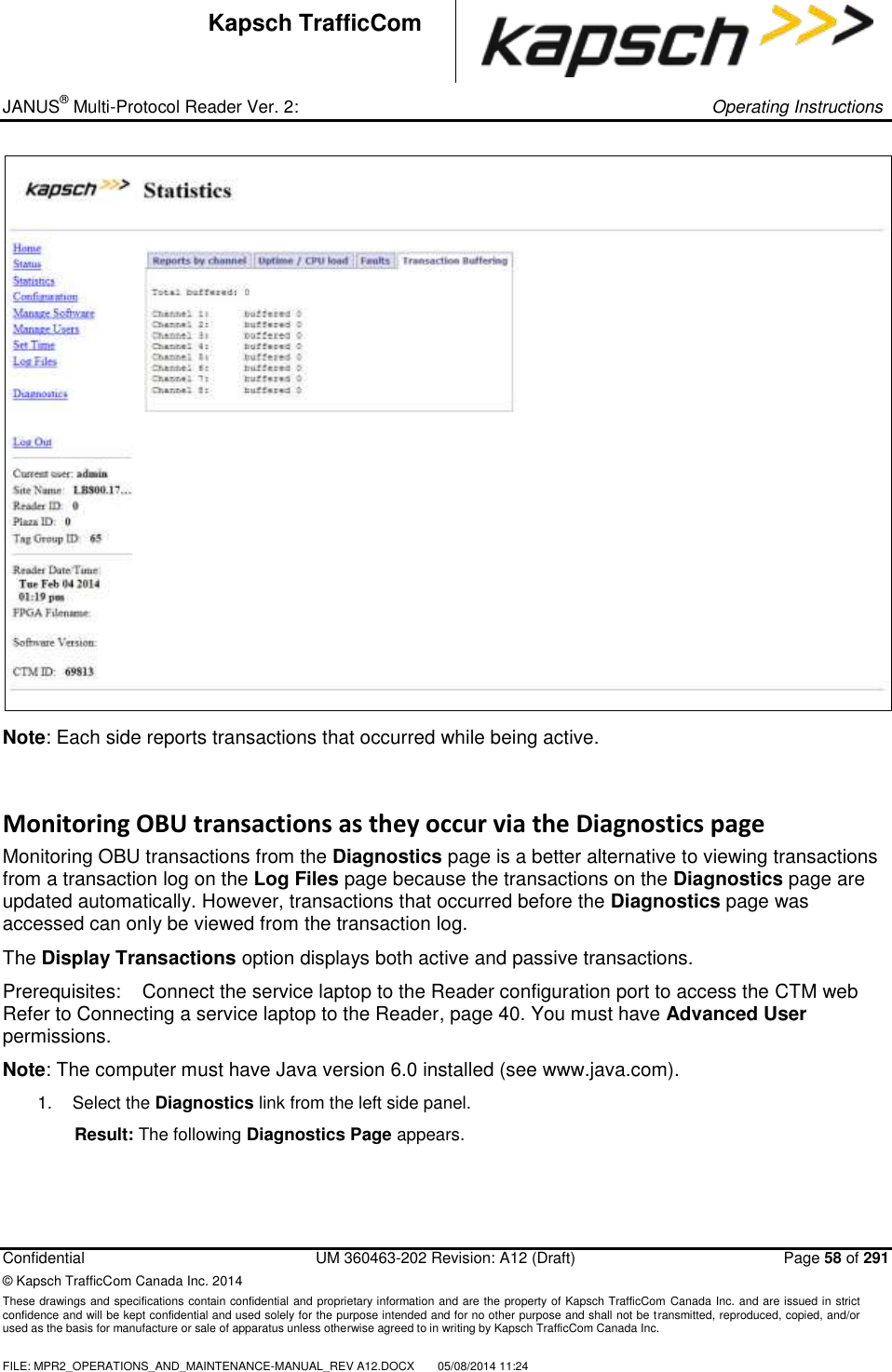
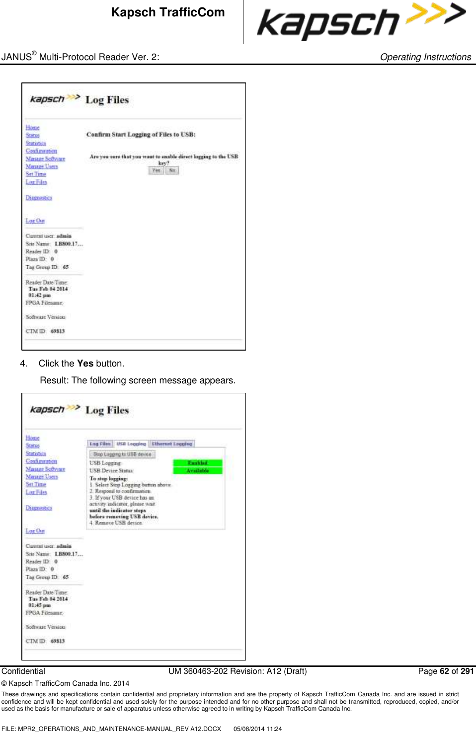
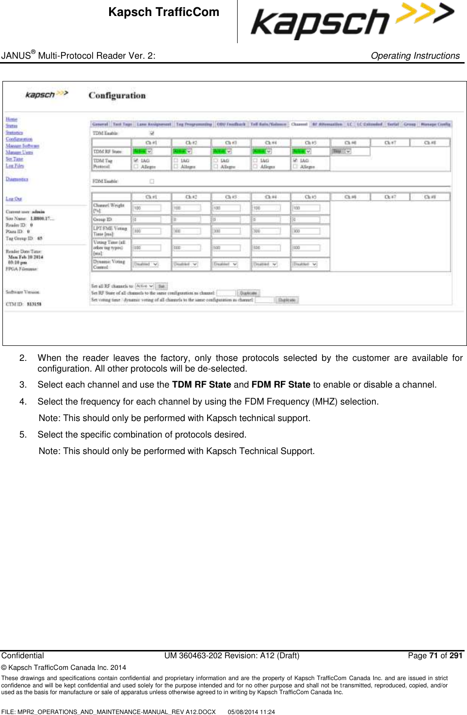
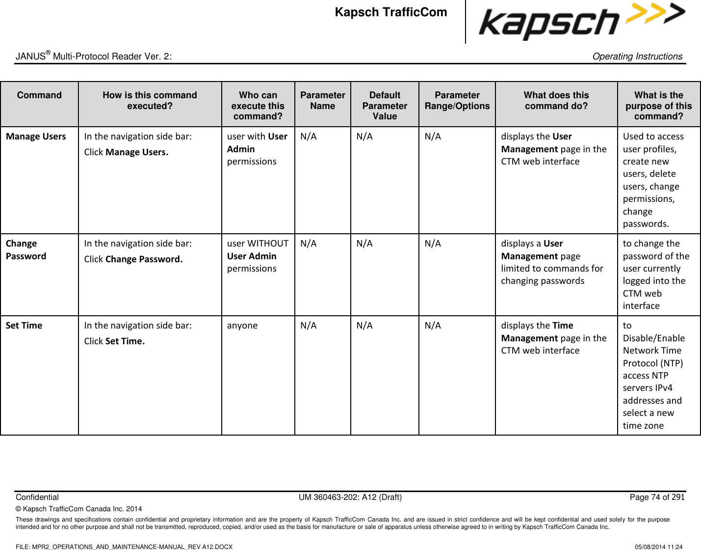
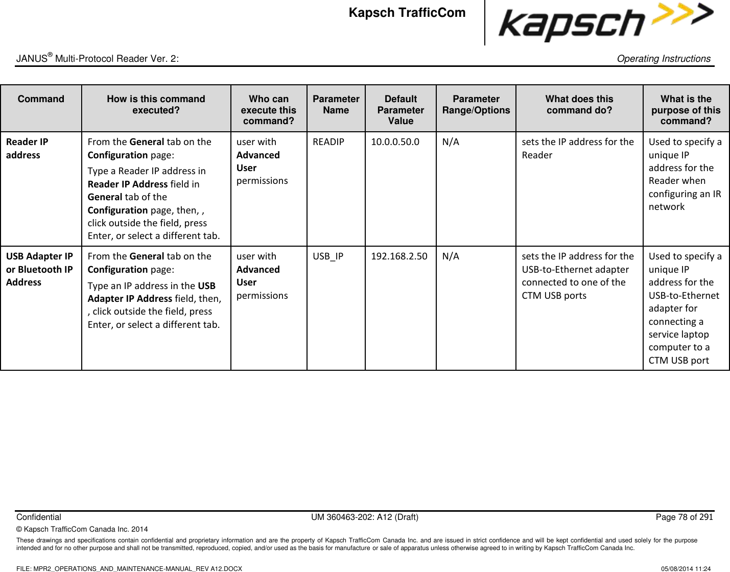
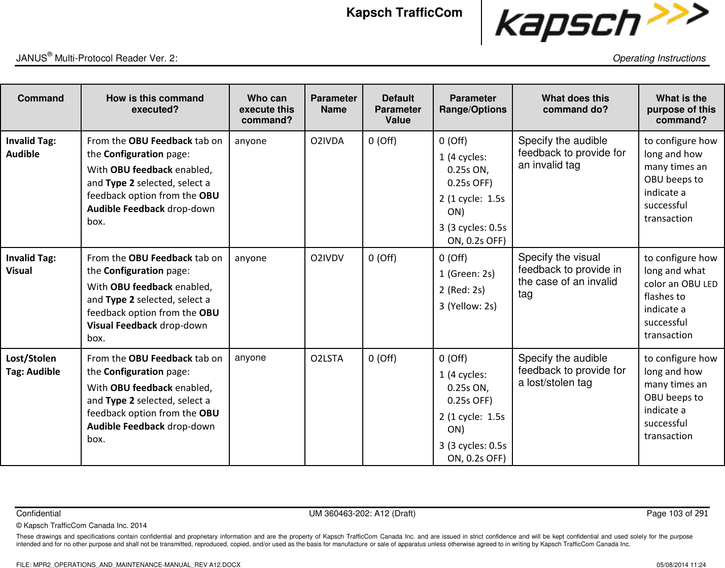
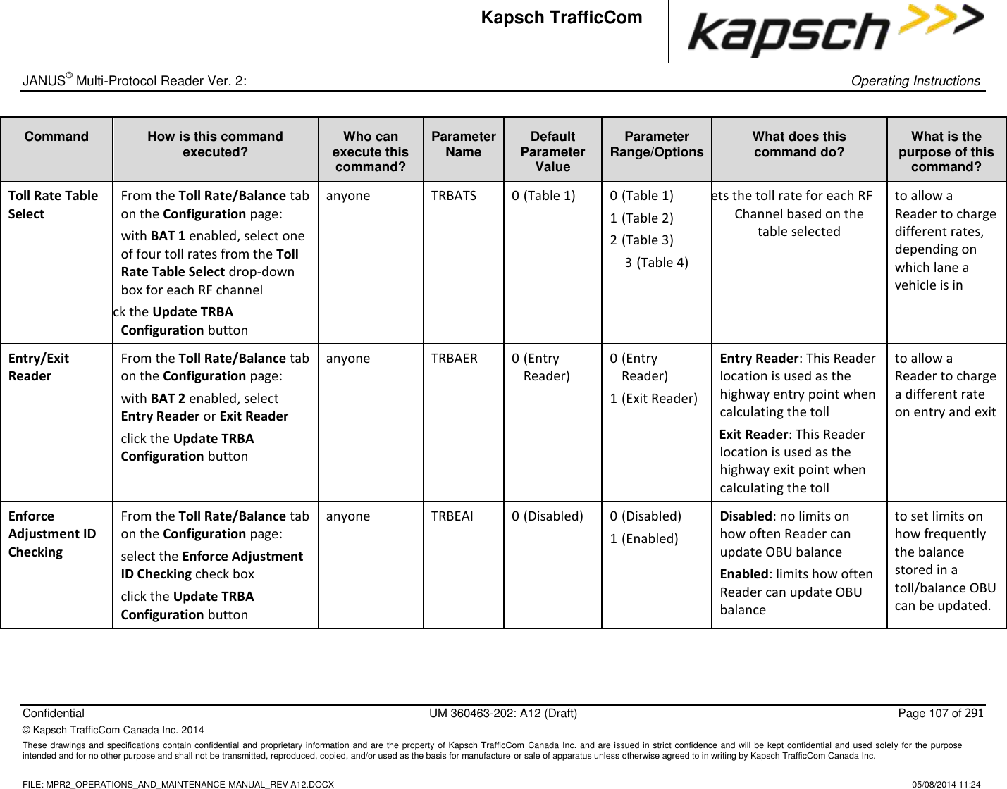
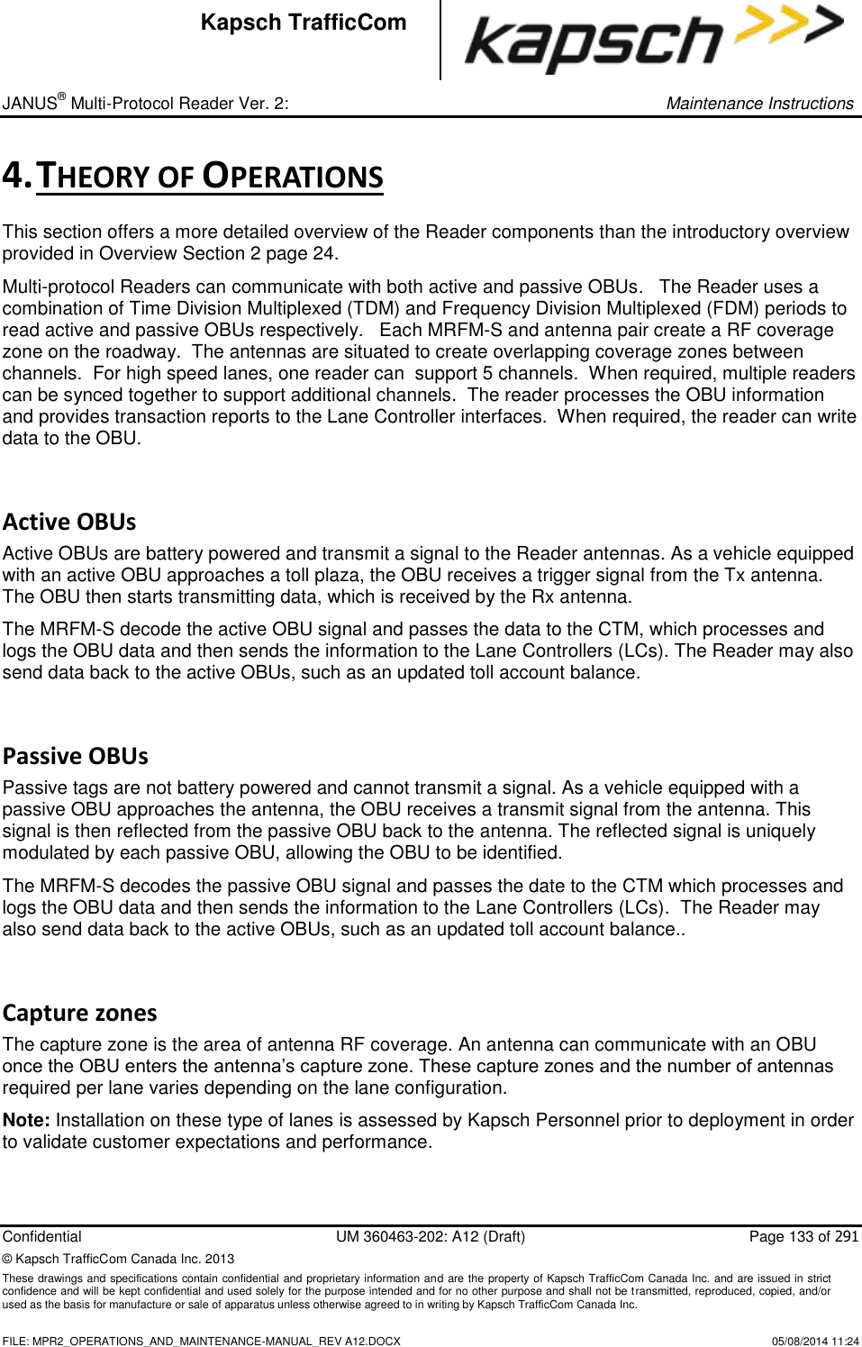
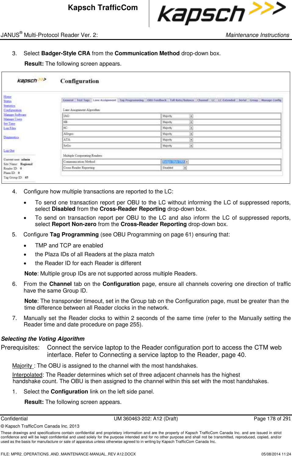
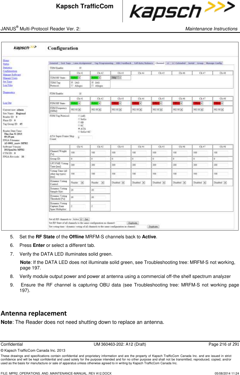
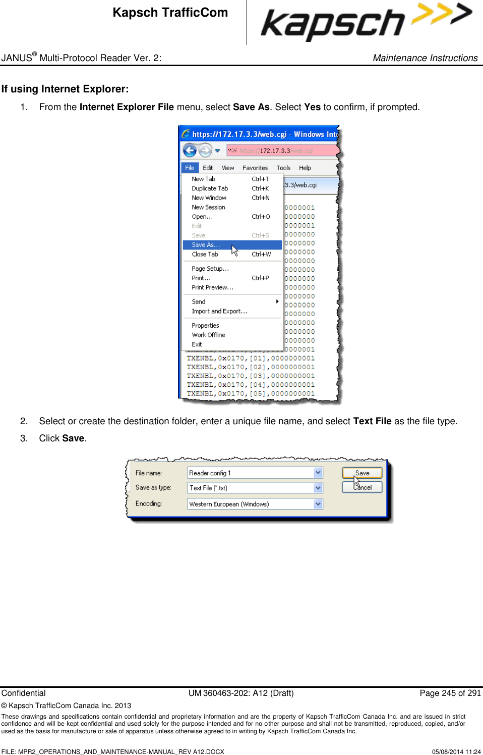
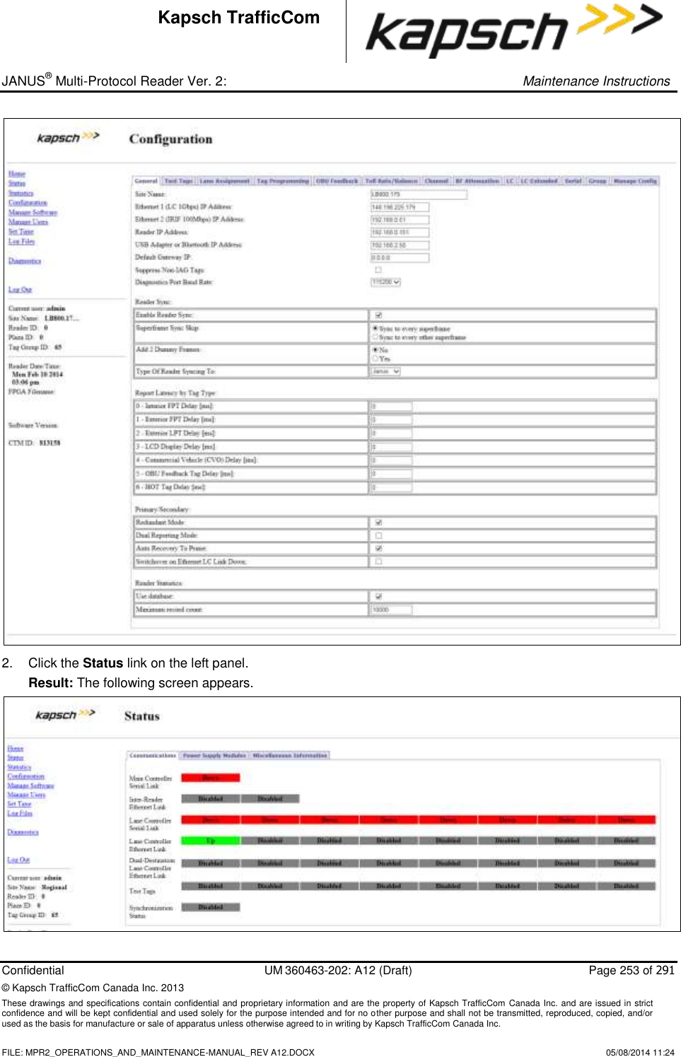
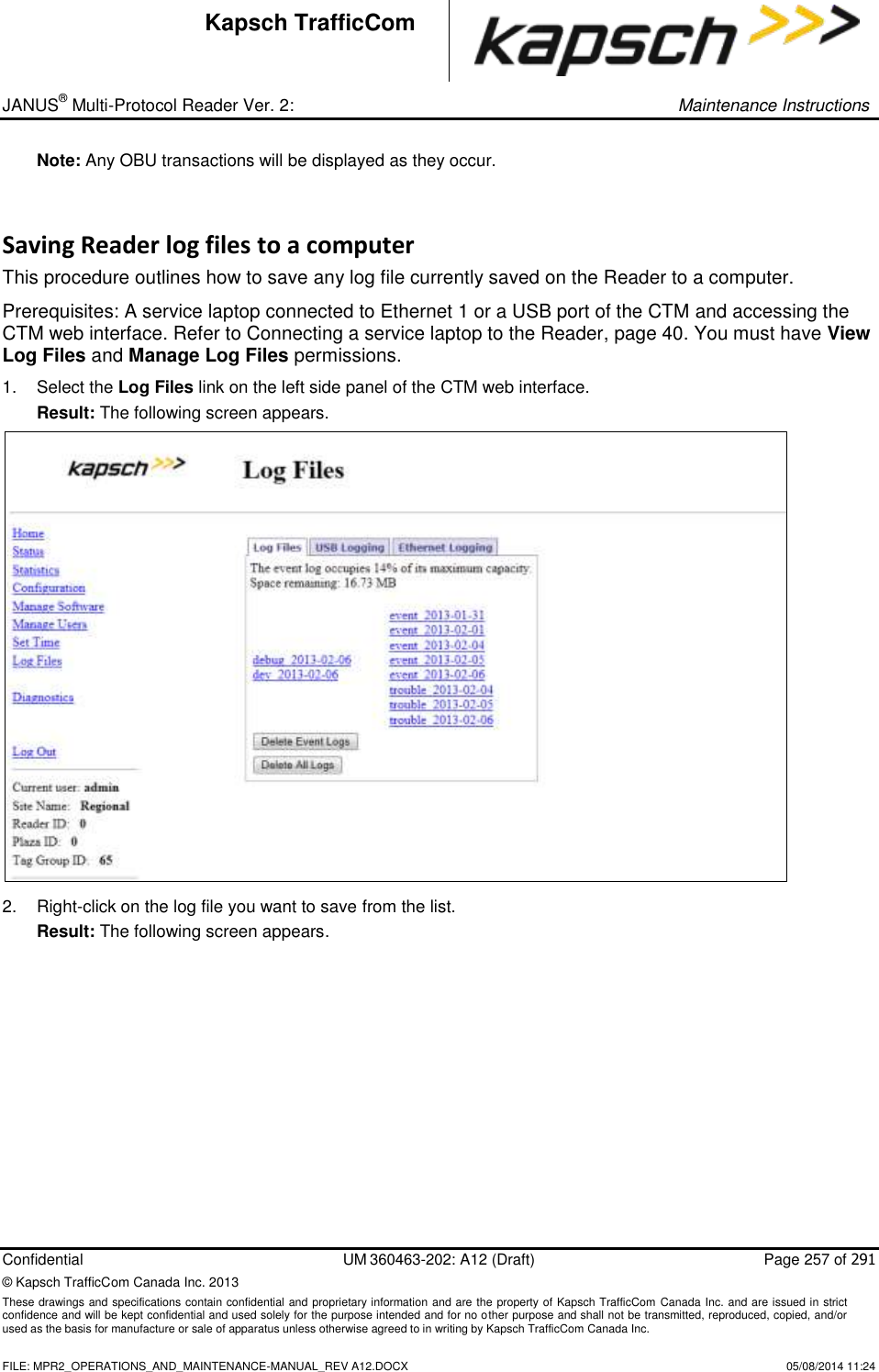
![_ JANUS® Multi-Protocol Reader Ver. 2: Operating Instructions Confidential UM 360463-202: A12 (Draft) Page 84 of 291 © Kapsch TrafficCom Canada Inc. 2014 These drawings and specifications contain confidential and proprietary information and are the property of Kapsch TrafficCom Canada Inc. and are issued in strict confidence and will be kept confidential and used solely for the purpose intended and for no other purpose and shall not be transmitted, reproduced, copied, and/or used as the basis for manufacture or sale of apparatus unless otherwise agreed to in writing by Kapsch TrafficCom Canada Inc. FILE: MPR2_OPERATIONS_AND_MAINTENANCE-MANUAL_REV A12.DOCX 05/08/2014 11:24 Kapsch TrafficCom Command How is this command executed? Who can execute this command? Parameter Name Default Parameter Value Parameter Range/Options What does this command do? What is the purpose of this command? 4 - Commercial Vehicle (CVO) Delay [ms] From the General tab on the Configuration page: Enter a time (in milliseconds) in the Commercial Vehicle (CVO) Delay field, then, , click outside the field, press Enter, or select a different tab. user with Advanced User permissions LYCTL4 0 0-5000 sets report delay time in milliseconds for CVO OBUs (Type 4). Used to slow down the transaction report of Type 4 OBUs to the LC for those legacy sites where the LC is expecting BADGER Reader timing 5 - OBU Feedback Tag Delay [ms] From the General tab on the Configuration page: Enter a time (in milliseconds) in the OBU Feedback Tag Delay field, then, , click outside the field, press Enter, or select a different tab. user with Advanced User permissions LYCTL5 0 0-5000 sets report delay time in milliseconds for CVO OBUs (Type 5). Used to slow down the transaction report of Type 5 OBUs to the LC for those legacy sites where the LC is expecting BADGER Reader timing](https://usermanual.wiki/KAPSCH-TRAFFICCOM-CANADA/802295A.Operations-and-Maintenance-Manual/User-Guide-2263970-Page-84.png)
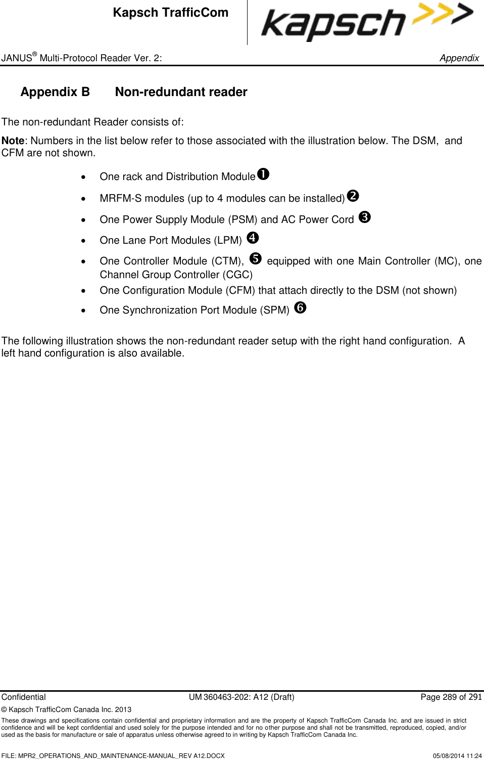
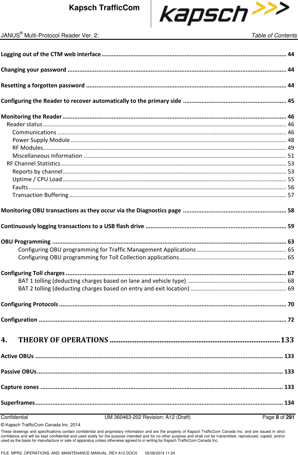
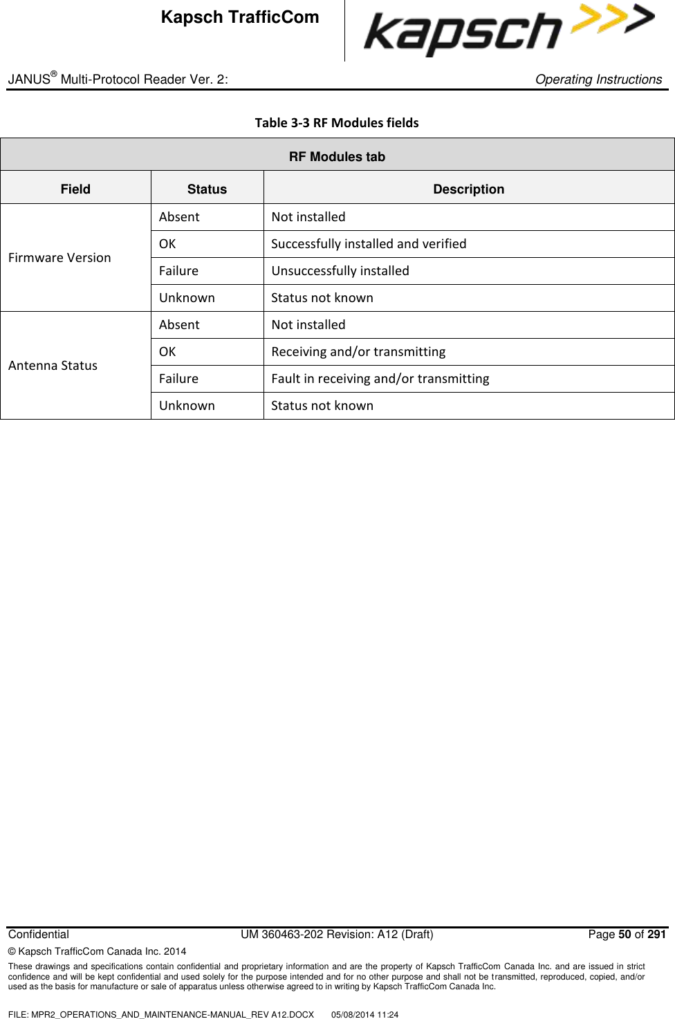
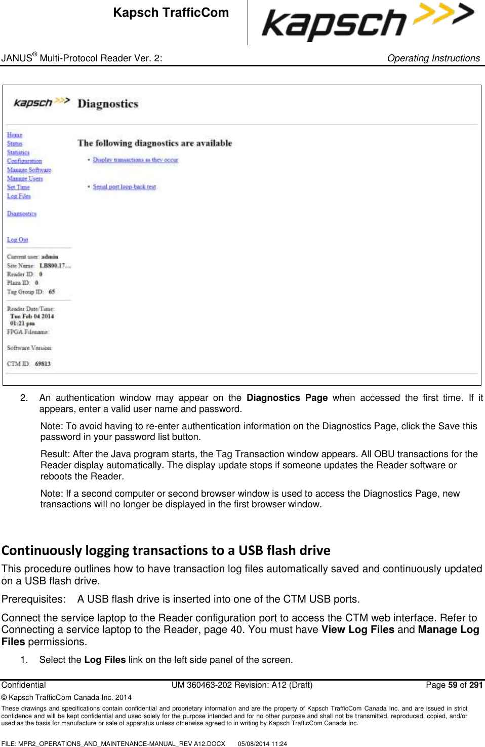
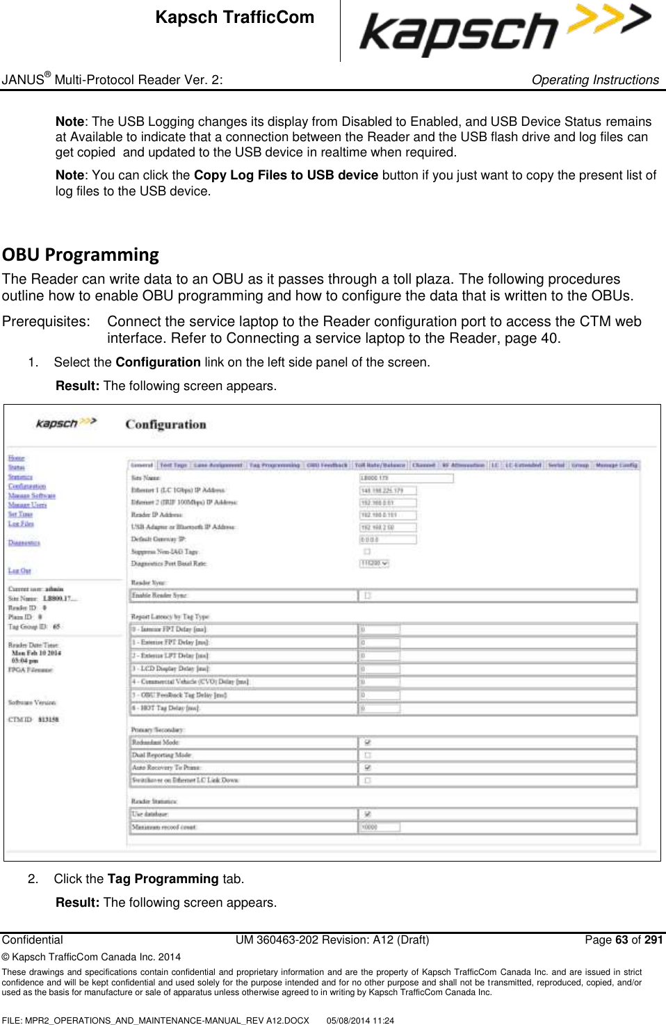
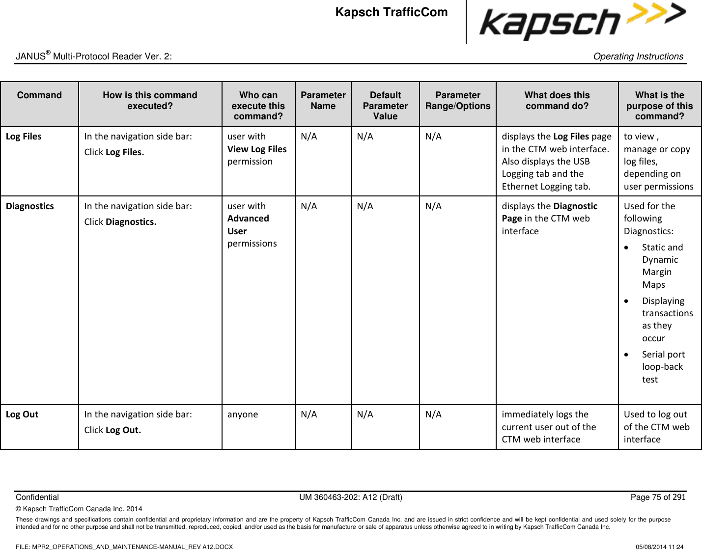
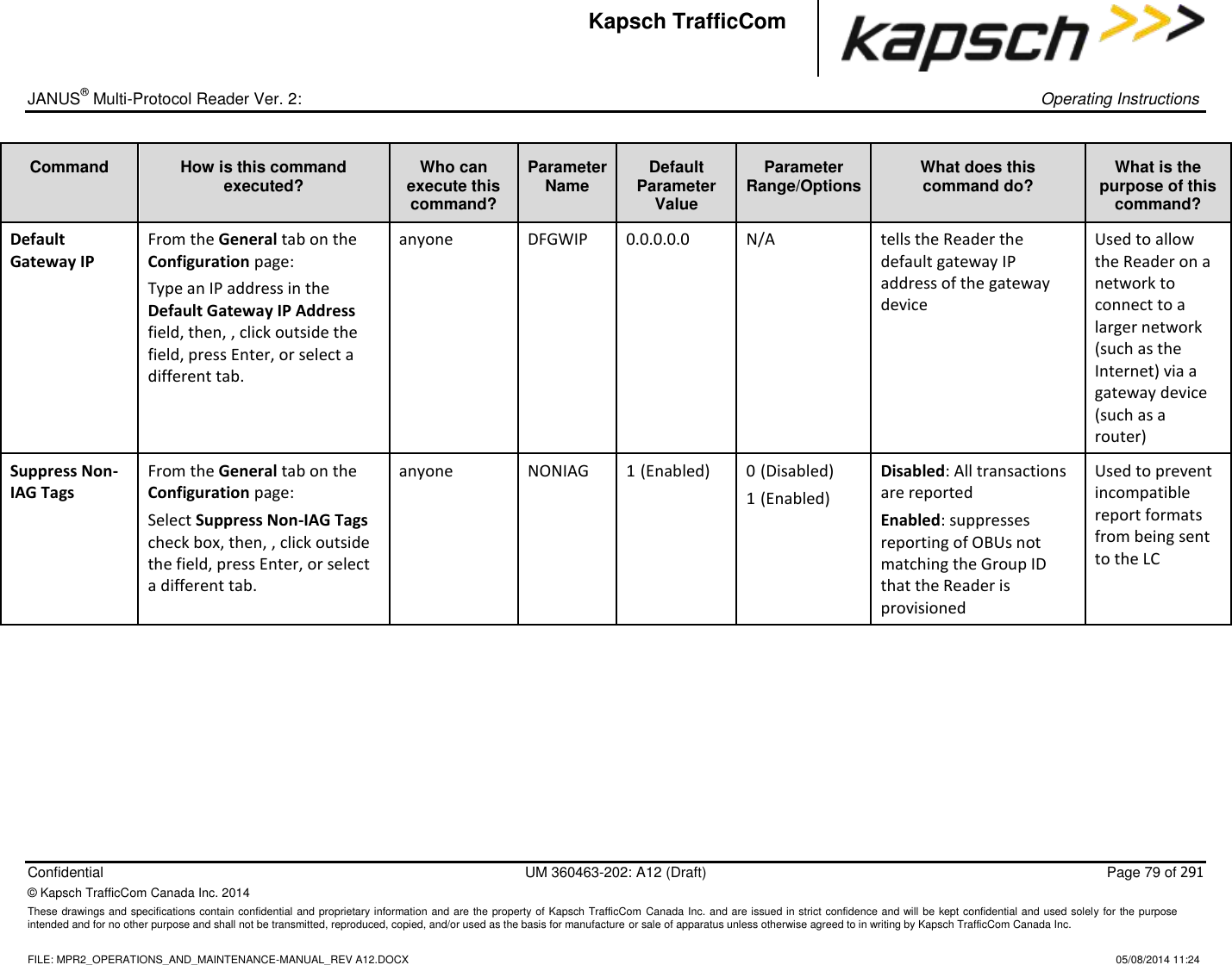
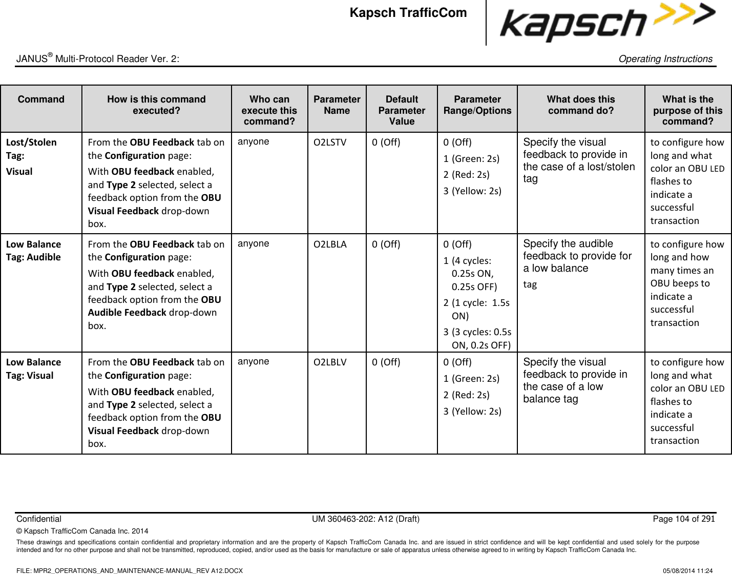
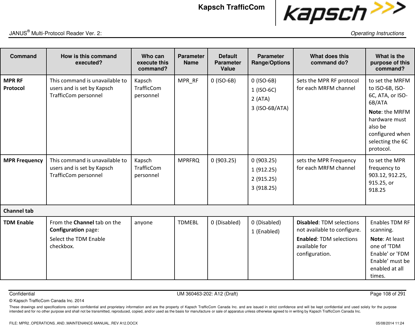
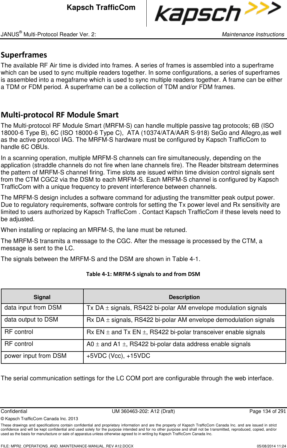
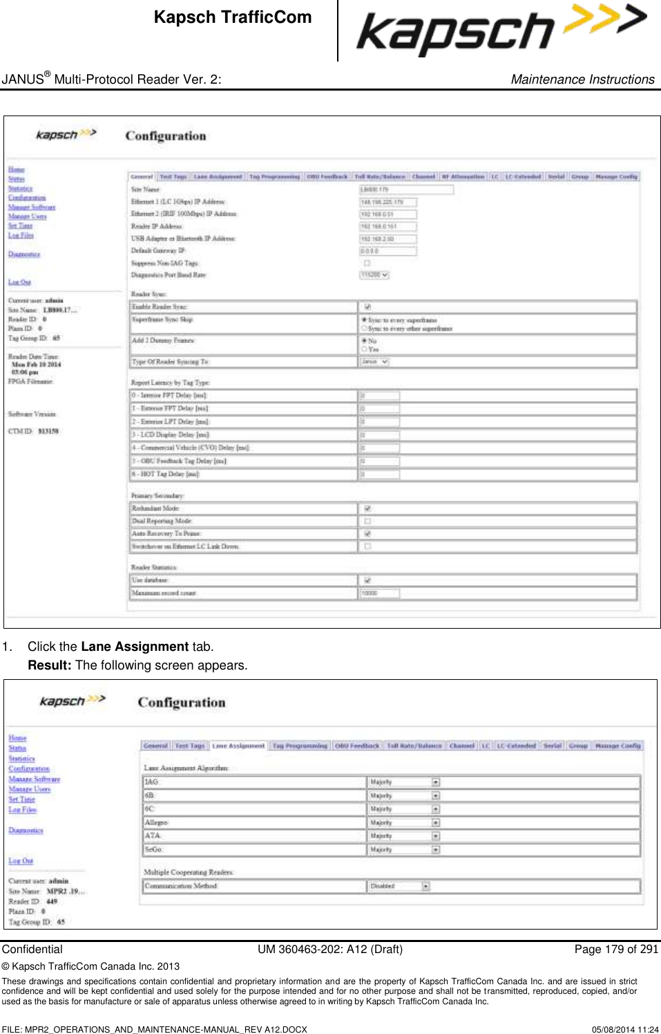
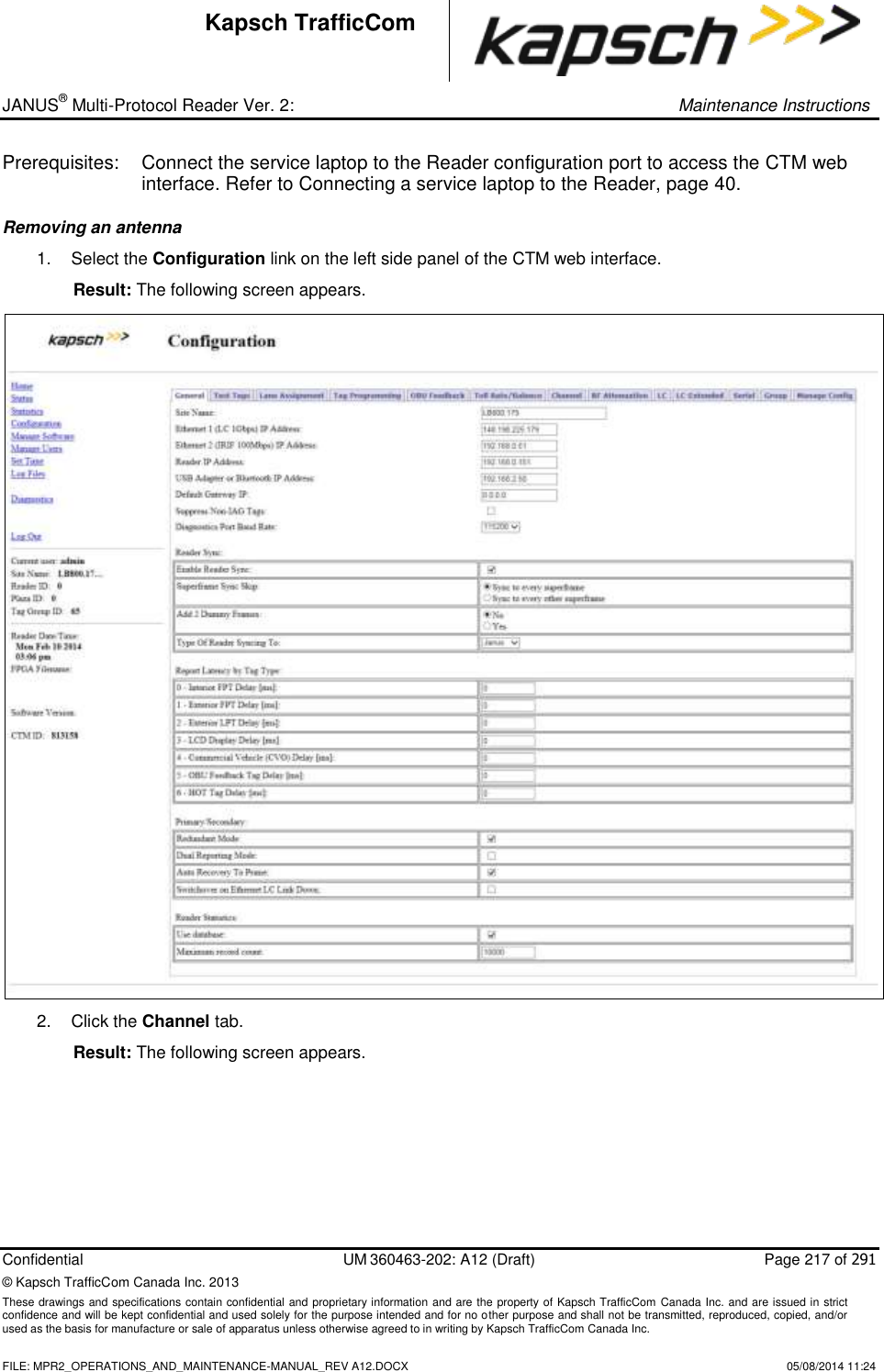
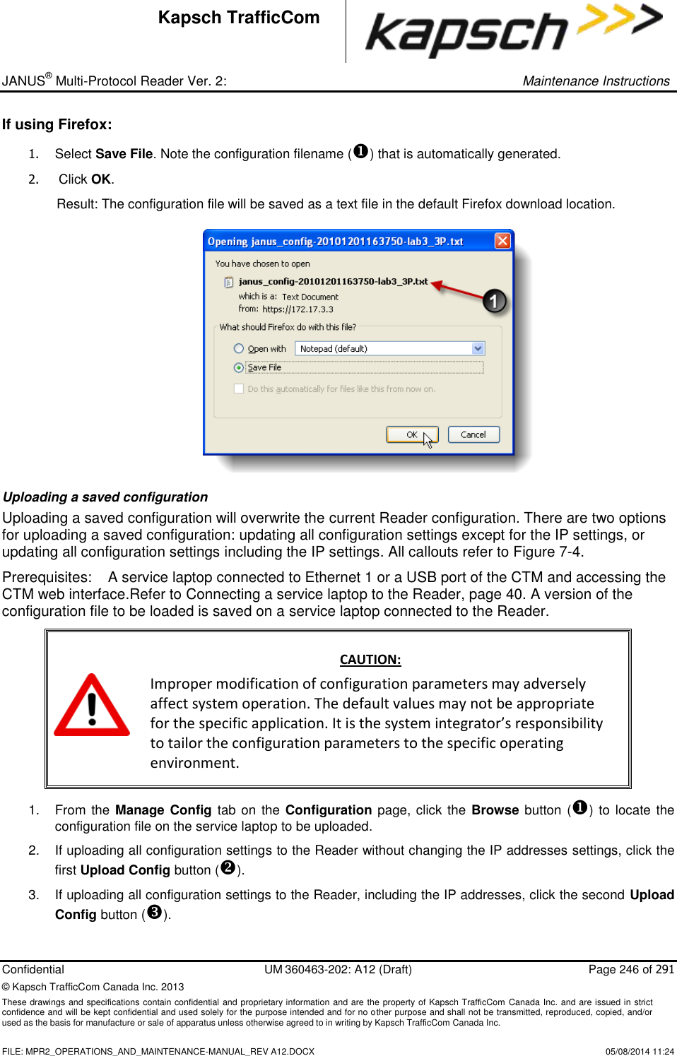
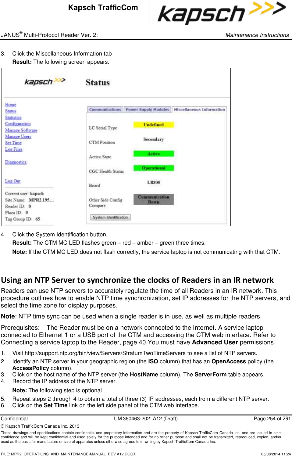
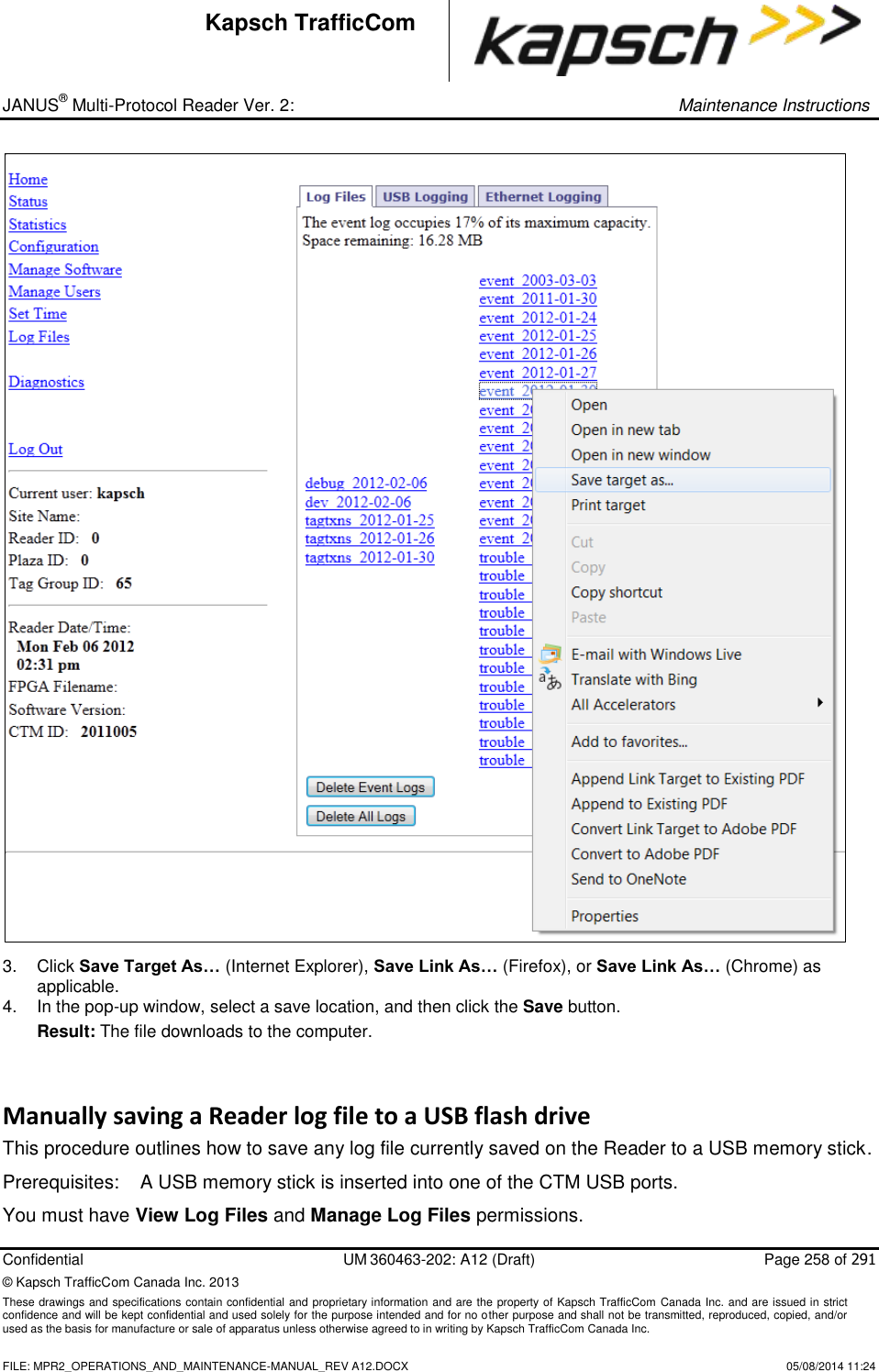
![_ JANUS® Multi-Protocol Reader Ver. 2: Operating Instructions Confidential UM 360463-202: A12 (Draft) Page 85 of 291 © Kapsch TrafficCom Canada Inc. 2014 These drawings and specifications contain confidential and proprietary information and are the property of Kapsch TrafficCom Canada Inc. and are issued in strict confidence and will be kept confidential and used solely for the purpose intended and for no other purpose and shall not be transmitted, reproduced, copied, and/or used as the basis for manufacture or sale of apparatus unless otherwise agreed to in writing by Kapsch TrafficCom Canada Inc. FILE: MPR2_OPERATIONS_AND_MAINTENANCE-MANUAL_REV A12.DOCX 05/08/2014 11:24 Kapsch TrafficCom Command How is this command executed? Who can execute this command? Parameter Name Default Parameter Value Parameter Range/Options What does this command do? What is the purpose of this command? 6 - HOT Tag Delay [ms] From the General tab on the Configuration page: Enter a time (in milliseconds) in the HOT Tag Delay field, then, , click outside the field, press Enter, or select a different tab. user with Advanced User permissions LYCTL6 0 0-5000 sets report delay time in milliseconds for CVO OBUs (Type 6). Used to slow down the transaction report of Type 6 OBUs to the LC for those legacy sites where the LC is expecting BADGER Reader timing Primary/Secondary Redundant Mode From the General tab on the Configuration page: Select the Redundant Mode check box, then, , click outside the field, press Enter, or select a different tab. user with Advanced User permissions RDNDNT 1 (Redundant Mode enabled) 0 (Disabled) 1 (Enabled) Disabled: Reader does not attempt to switch to redundant side when a failure occurs. Enabled: Reader attempts to switch to redundant side when a failure occurs (depending on configuration) Used to enable the Reader to automatically switch over to the redundant side when a failure occurs](https://usermanual.wiki/KAPSCH-TRAFFICCOM-CANADA/802295A.Operations-and-Maintenance-Manual/User-Guide-2263970-Page-85.png)
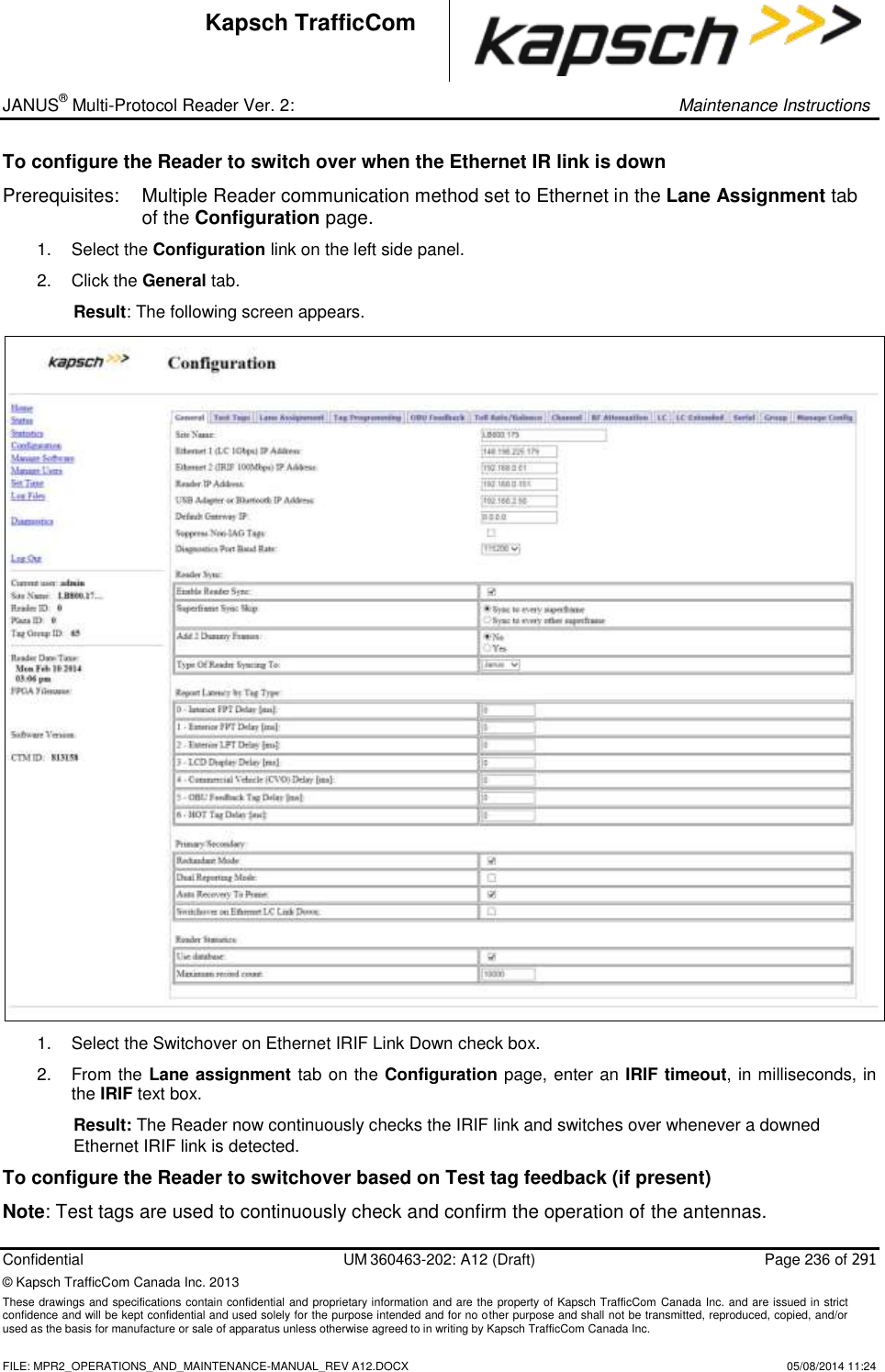
![_ JANUS® Multi-Protocol Reader Ver. 2: Operating Instructions Confidential UM 360463-202: A12 (Draft) Page 91 of 291 © Kapsch TrafficCom Canada Inc. 2014 These drawings and specifications contain confidential and proprietary information and are the property of Kapsch TrafficCom Canada Inc. and are issued in strict confidence and will be kept confidential and used solely for the purpose intended and for no other purpose and shall not be transmitted, reproduced, copied, and/or used as the basis for manufacture or sale of apparatus unless otherwise agreed to in writing by Kapsch TrafficCom Canada Inc. FILE: MPR2_OPERATIONS_AND_MAINTENANCE-MANUAL_REV A12.DOCX 05/08/2014 11:24 Kapsch TrafficCom Command How is this command executed? Who can execute this command? Parameter Name Default Parameter Value Parameter Range/Options What does this command do? What is the purpose of this command? Cross-Reader Reporting From the Lane Assignment tab on the Configuration page, with Badger-style CRA or Ethernet communication method enabled: Select Disabled, Report All, or Report Non-Zero from the Cross-Reader Reporting drop-down box, then, press Enter or select a different tab. user with Advanced User permissions CRARPT 0 (Disabled) 0 (Disabled) 1 (Report All) 2 (Report Non-Zero) Disabled: Reader is not set to communicate with other Readers. Report All results in all transactions being sent to the LC Report Non-Zero informs the LC of suppressed transactions to set which transactions are sent to LC in multi-reader configurations IRIF Timeout [ms] (make sure the TTO values of all IRIF readers are the same) From the Lane Assignment tab on the Configuration page, with Ethernet communication method enabled: Enter a time, in milliseconds, in the IRIF Timeout field, then, press Enter or select a different tab. user with Advanced User permissions IRIFTO 50 30-5000 sets IRIF timeout time sets the threshold for determining an IR network problem and enable a switchover if enabled](https://usermanual.wiki/KAPSCH-TRAFFICCOM-CANADA/802295A.Operations-and-Maintenance-Manual/User-Guide-2263970-Page-91.png)
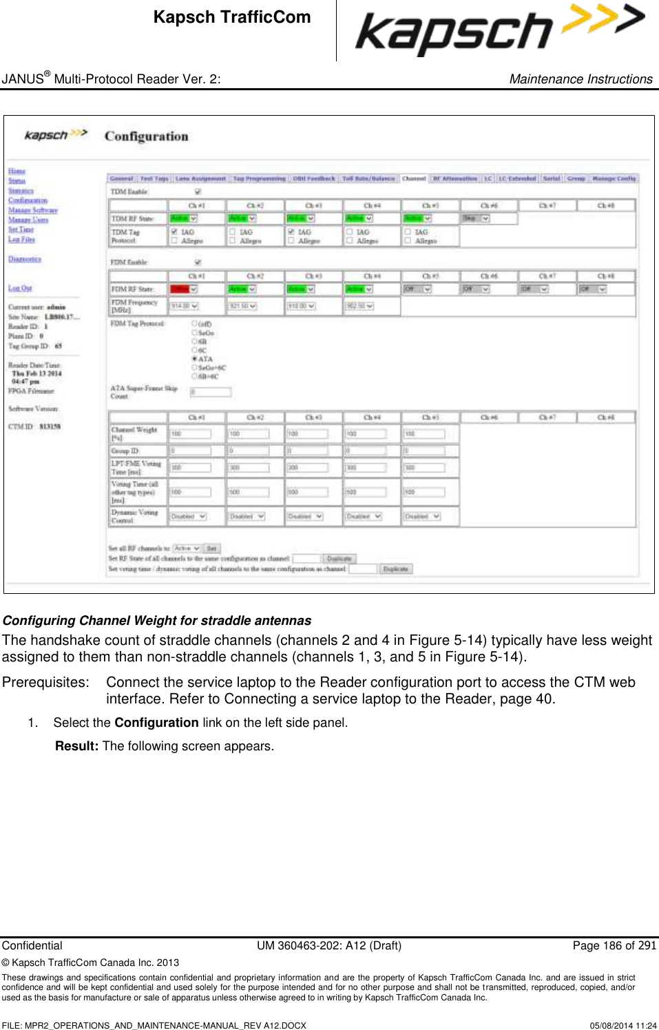
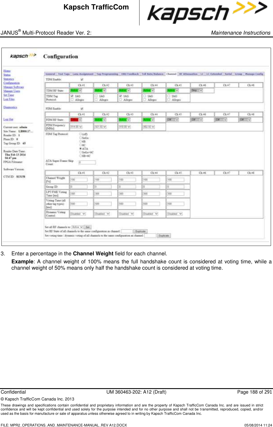
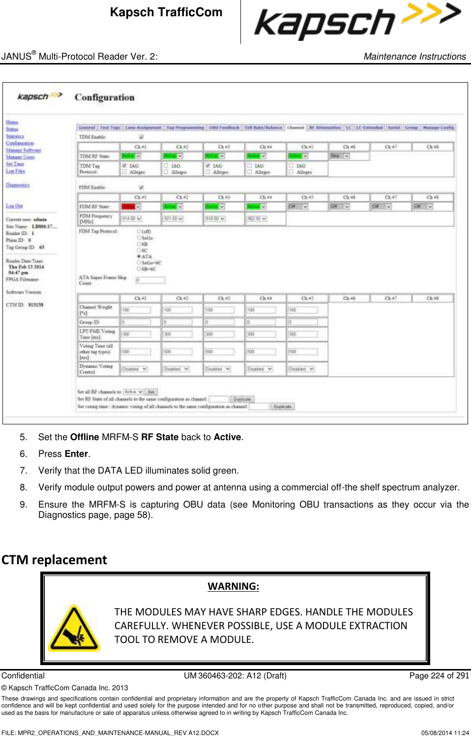
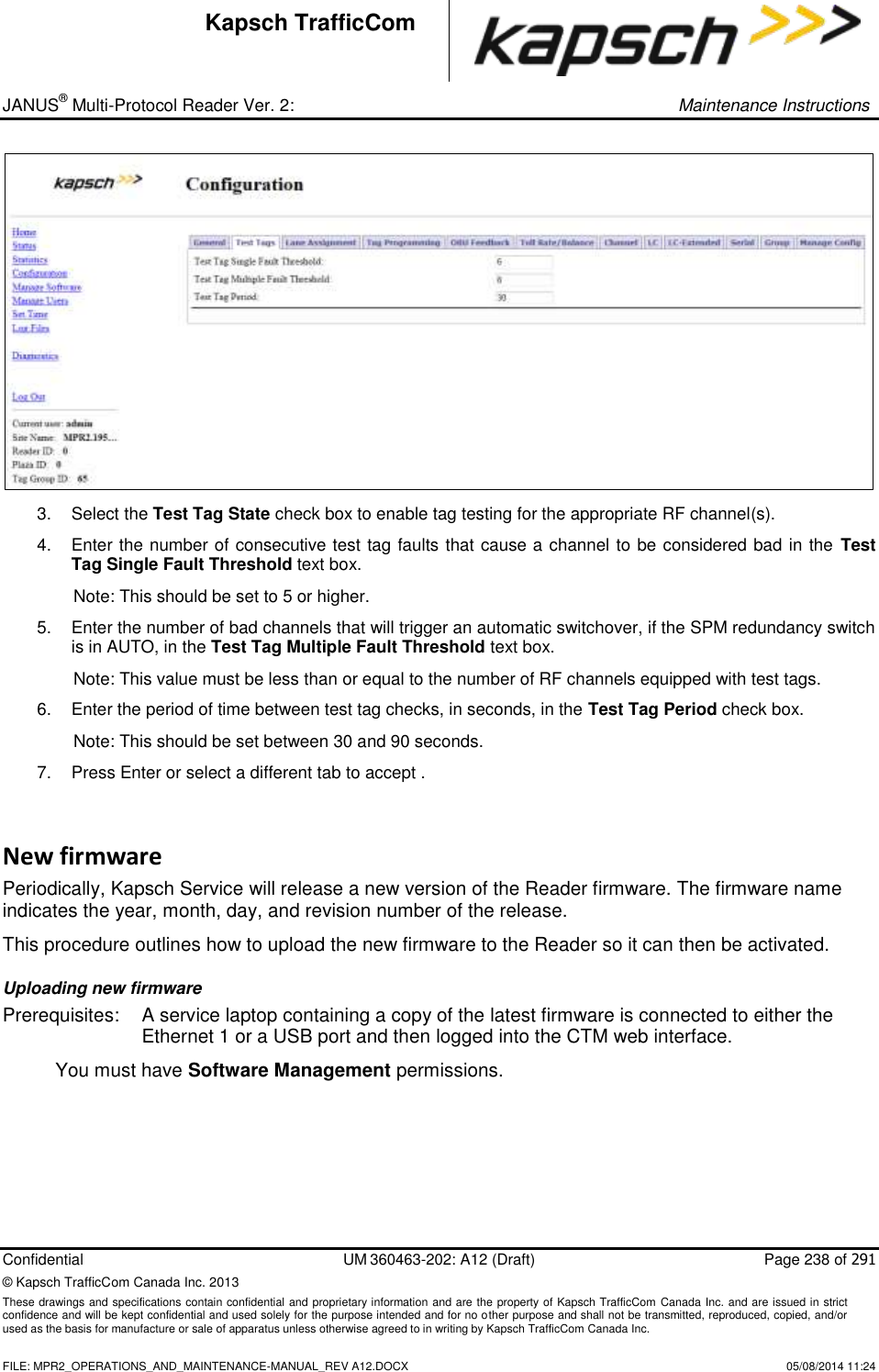
![_ JANUS® Multi-Protocol Reader Ver. 2: Operating Instructions Confidential UM 360463-202: A12 (Draft) Page 113 of 291 © Kapsch TrafficCom Canada Inc. 2014 These drawings and specifications contain confidential and proprietary information and are the property of Kapsch TrafficCom Canada Inc. and are issued in strict confidence and will be kept confidential and used solely for the purpose intended and for no other purpose and shall not be transmitted, reproduced, copied, and/or used as the basis for manufacture or sale of apparatus unless otherwise agreed to in writing by Kapsch TrafficCom Canada Inc. FILE: MPR2_OPERATIONS_AND_MAINTENANCE-MANUAL_REV A12.DOCX 05/08/2014 11:24 Kapsch TrafficCom Command How is this command executed? Who can execute this command? Parameter Name Default Parameter Value Parameter Range/Options What does this command do? What is the purpose of this command? ATA Super-Frame Skip Count From the Channel tab on the Configuration page: anyone ATASKP 0 0-5 This value defines the ON and OFF times for the ATA protocol FDM frames. I.e. how many super-frames should be generated without doing ATA before a super-frame with ATA should be created. 0 means 'do ATA on every super-frame' 1 means 'do ATA every other super-frame', etc... Used for 6B, 6C, Sego protocols Channel Weight [%] From the Channel tab on the Configuration page: Type the Channel Weight as a percent in the appropriate fields. user with Advanced User permissions RFWGHT 100 0-100 Enter a value from 0 to 100. At lane assignment time, the reader applies the weighting factor to all channels seeing the same transponder in a group. A channel weight of 50 means only half of the handshakes are used in comparing with adjacent channels. Typically a value other than 100 is used only for channels that straddle two physical lanes. Used by all protocols](https://usermanual.wiki/KAPSCH-TRAFFICCOM-CANADA/802295A.Operations-and-Maintenance-Manual/User-Guide-2263970-Page-113.png)
![_ JANUS® Multi-Protocol Reader Ver. 2: Operating Instructions Confidential UM 360463-202: A12 (Draft) Page 114 of 291 © Kapsch TrafficCom Canada Inc. 2014 These drawings and specifications contain confidential and proprietary information and are the property of Kapsch TrafficCom Canada Inc. and are issued in strict confidence and will be kept confidential and used solely for the purpose intended and for no other purpose and shall not be transmitted, reproduced, copied, and/or used as the basis for manufacture or sale of apparatus unless otherwise agreed to in writing by Kapsch TrafficCom Canada Inc. FILE: MPR2_OPERATIONS_AND_MAINTENANCE-MANUAL_REV A12.DOCX 05/08/2014 11:24 Kapsch TrafficCom Command How is this command executed? Who can execute this command? Parameter Name Default Parameter Value Parameter Range/Options What does this command do? What is the purpose of this command? Group ID From the Channel tab on the Configuration page: Type the Group ID in the appropriate fields. user with Advanced User permissions RFGPID 0 0-7 By default all channels are in one group, such that any cross lane reads within the group generate only one transaction. By specifying different group IDs, multiple independent coverage zones can be created. This is useful for certain applications. Used by all protocols LPT/FME Voting time [ms] From the Channel tab on the Configuration page: Type the voting time in the appropriate fields. user with Advanced User permissions LPTVTO 300 0-9999 Specify the time after the initial entry of the transponder into the capture zone after which a report is generated. This is a trade-off between lane assignments versus latency. A value of 0 means no voting, subject to the Programming Timeout parameter. Specific to [L]icense [P]late [T]ags only. Used by all protocols](https://usermanual.wiki/KAPSCH-TRAFFICCOM-CANADA/802295A.Operations-and-Maintenance-Manual/User-Guide-2263970-Page-114.png)
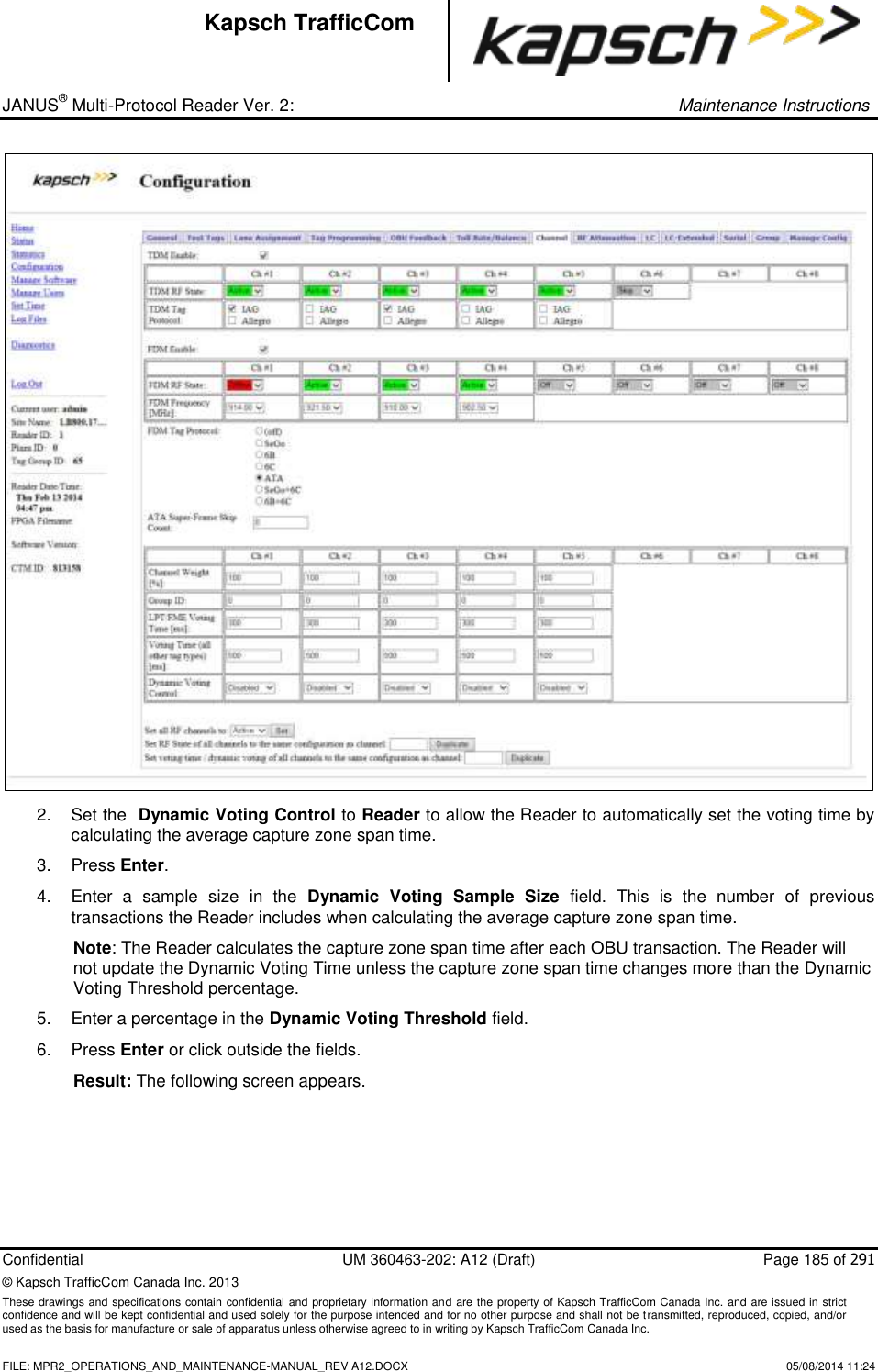
![_ JANUS® Multi-Protocol Reader Ver. 2: Operating Instructions Confidential UM 360463-202: A12 (Draft) Page 115 of 291 © Kapsch TrafficCom Canada Inc. 2014 These drawings and specifications contain confidential and proprietary information and are the property of Kapsch TrafficCom Canada Inc. and are issued in strict confidence and will be kept confidential and used solely for the purpose intended and for no other purpose and shall not be transmitted, reproduced, copied, and/or used as the basis for manufacture or sale of apparatus unless otherwise agreed to in writing by Kapsch TrafficCom Canada Inc. FILE: MPR2_OPERATIONS_AND_MAINTENANCE-MANUAL_REV A12.DOCX 05/08/2014 11:24 Kapsch TrafficCom Command How is this command executed? Who can execute this command? Parameter Name Default Parameter Value Parameter Range/Options What does this command do? What is the purpose of this command? Voting Time (all other tag types) [ms] From the Channel tab on the Configuration page: Type the Voting Time for all other tag types in the appropriate fields. user with Advanced User permissions VOTETO 100 0-9999 Specify the time after the initial entry of the transponder into the capture zone, subject to the Programming Timeout parameter. Used by all protocols Dynamic Voting Control From the Channel tab on the Configuration page: Select Disabled or Reader from the Dynamic voting control drop-down box (LC Speed and LC Ends are not supported), then, press Enter or select a different tab. user with Advanced User permissions DVCTRL 0 (Disabled) 0 (Disabled) 1 (Reader) 2 (LC Speed) 3 (LC End) Disabled: no voting control Reader: the Reader monitors the average time an OBU is in the capture zone and uses this time to determine an appropriate voting time LC Speed: not currently supported LC End: not currently supported to set type of voting control](https://usermanual.wiki/KAPSCH-TRAFFICCOM-CANADA/802295A.Operations-and-Maintenance-Manual/User-Guide-2263970-Page-115.png)
![_ JANUS® Multi-Protocol Reader Ver. 2: Operating Instructions Confidential UM 360463-202: A12 (Draft) Page 116 of 291 © Kapsch TrafficCom Canada Inc. 2014 These drawings and specifications contain confidential and proprietary information and are the property of Kapsch TrafficCom Canada Inc. and are issued in strict confidence and will be kept confidential and used solely for the purpose intended and for no other purpose and shall not be transmitted, reproduced, copied, and/or used as the basis for manufacture or sale of apparatus unless otherwise agreed to in writing by Kapsch TrafficCom Canada Inc. FILE: MPR2_OPERATIONS_AND_MAINTENANCE-MANUAL_REV A12.DOCX 05/08/2014 11:24 Kapsch TrafficCom Command How is this command executed? Who can execute this command? Parameter Name Default Parameter Value Parameter Range/Options What does this command do? What is the purpose of this command? Dynamic Voting Sample Size From the Channel tab on the Configuration page: With Dynamic Voting Control set to Reader, enter the desired number of samples, then, press Enter or select a different tab. user with Advanced User permissions DVSPSZ 20 1-50 Sets the sample size used in the Dynamic Voting Calculation to configure the Dynamic Voting Control calculation. The number entered here is the number of previous transactions used when calculating the average voting time Dynamic Voting Threshold [%] From the Channel tab on the Configuration page: With Dynamic Voting Control set to Reader, enter the voting threshold percentage in the Dynamic Voting Threshold field, then, press Enter or select a different tab. user with Advanced User permissions DVTHSD 20 5-100 sets the voting threshold percentage to configure when the average Voting time is adjusted. The Voting time will only be updated when the Reader determines the percent change is larger than the threshold entered here](https://usermanual.wiki/KAPSCH-TRAFFICCOM-CANADA/802295A.Operations-and-Maintenance-Manual/User-Guide-2263970-Page-116.png)


![_ JANUS® Multi-Protocol Reader Ver. 2: Maintenance Instructions Confidential UM 360463-202: A12 (Draft) Page 143 of 291 © Kapsch TrafficCom Canada Inc. 2013 These drawings and specifications contain confidential and proprietary information and are the property of Kapsch TrafficCom Canada Inc. and are issued in strict confidence and will be kept confidential and used solely for the purpose intended and for no other purpose and shall not be transmitted, reproduced, copied, and/or used as the basis for manufacture or sale of apparatus unless otherwise agreed to in writing by Kapsch TrafficCom Canada Inc. FILE: MPR2_OPERATIONS_AND_MAINTENANCE-MANUAL_REV A12.DOCX 05/08/2014 11:24 Kapsch TrafficCom Trouble Logs Unusual Reader issues generate trouble logs (for example, if a switchover has occurred). During service, the technician should first examine these trouble log files to see if there are any reported issues with the Reader. Examine the Log Files page for instances of one or more trouble <date> file in the list of log files. A typical report in a trouble log is: 2010-05-31T10:52:35.723+00:00 [lab3_5] SYNCR: Reader SYNC lost Note: As an alternative, Kapsch Service can remotely connect to the Reader and examine the trouble log to quickly identify and resolve any issues. It is up to the system administrator or integrator to determine when to grant Kapsch Service remote access to the LC network IP addresses. The following list depicts the possible sources of trouble messages found in the trouble <date> file. No detection of a CFM backplane memory module. The Status file integrity check fails. Possible cause: there may be data for up to 40 million OBUs in a Status file. The Reader software forced a switchover on detection of: o Failed CGC health o Failed serial LC link (when enabled). Possible cause: a fault external to the Reader o Failed Ethernet LC link (when enabled). Possible cause: a fault external to the Reader o Failed Ethernet inter-Reader link (when enabled). Possible cause: a fault external to the Reader](https://usermanual.wiki/KAPSCH-TRAFFICCOM-CANADA/802295A.Operations-and-Maintenance-Manual/User-Guide-2263970-Page-143.png)
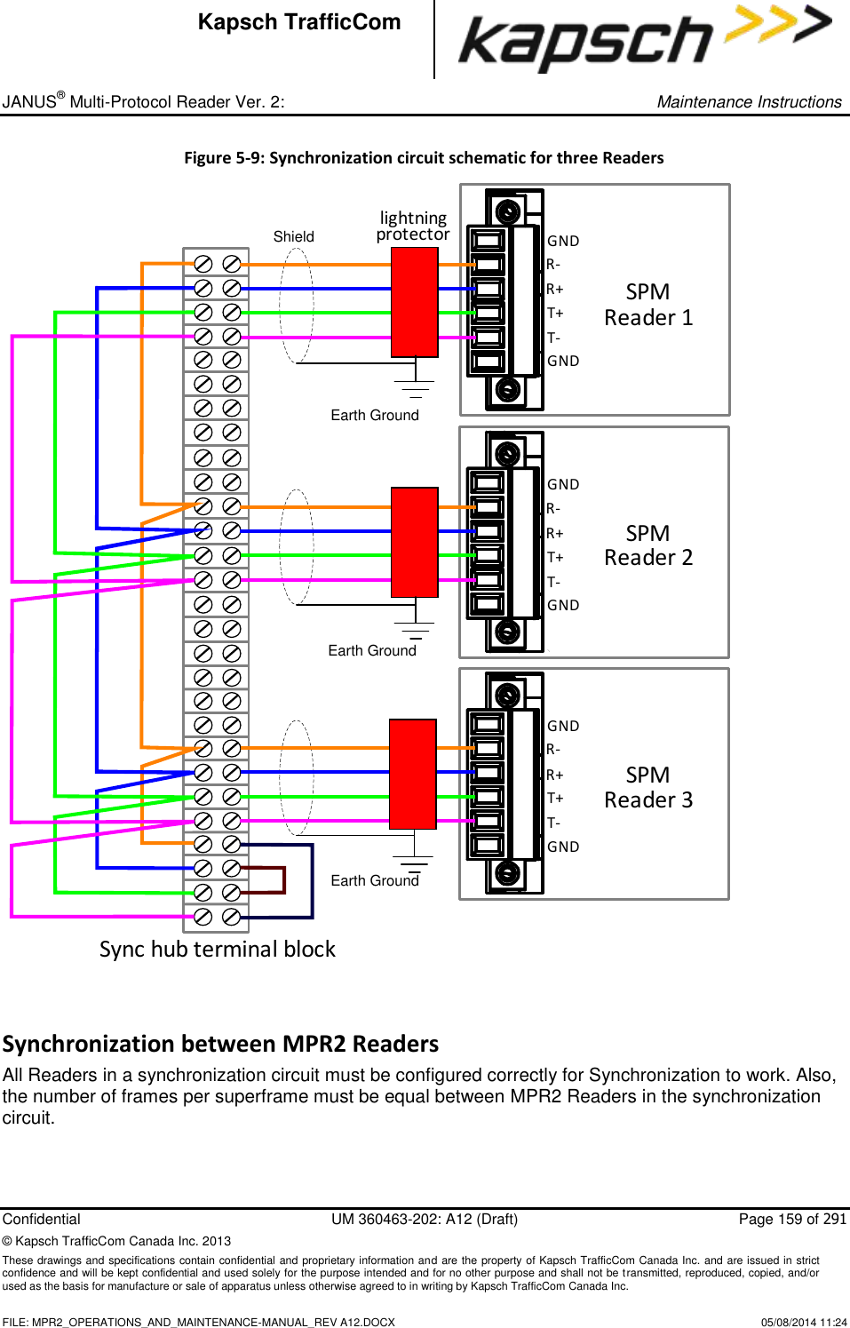


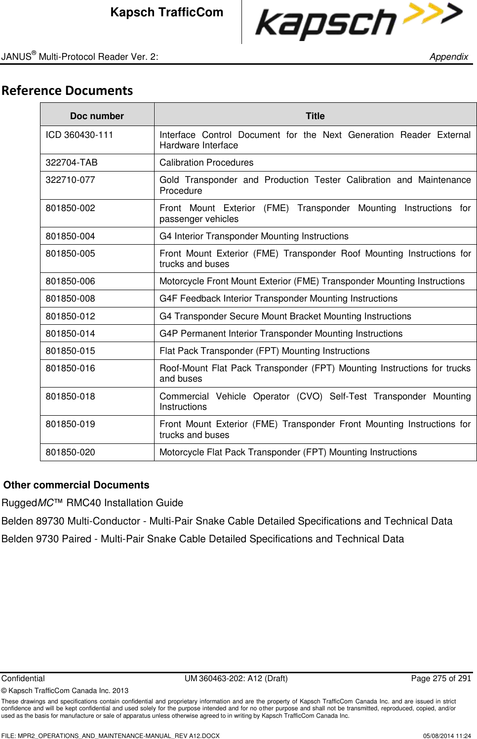
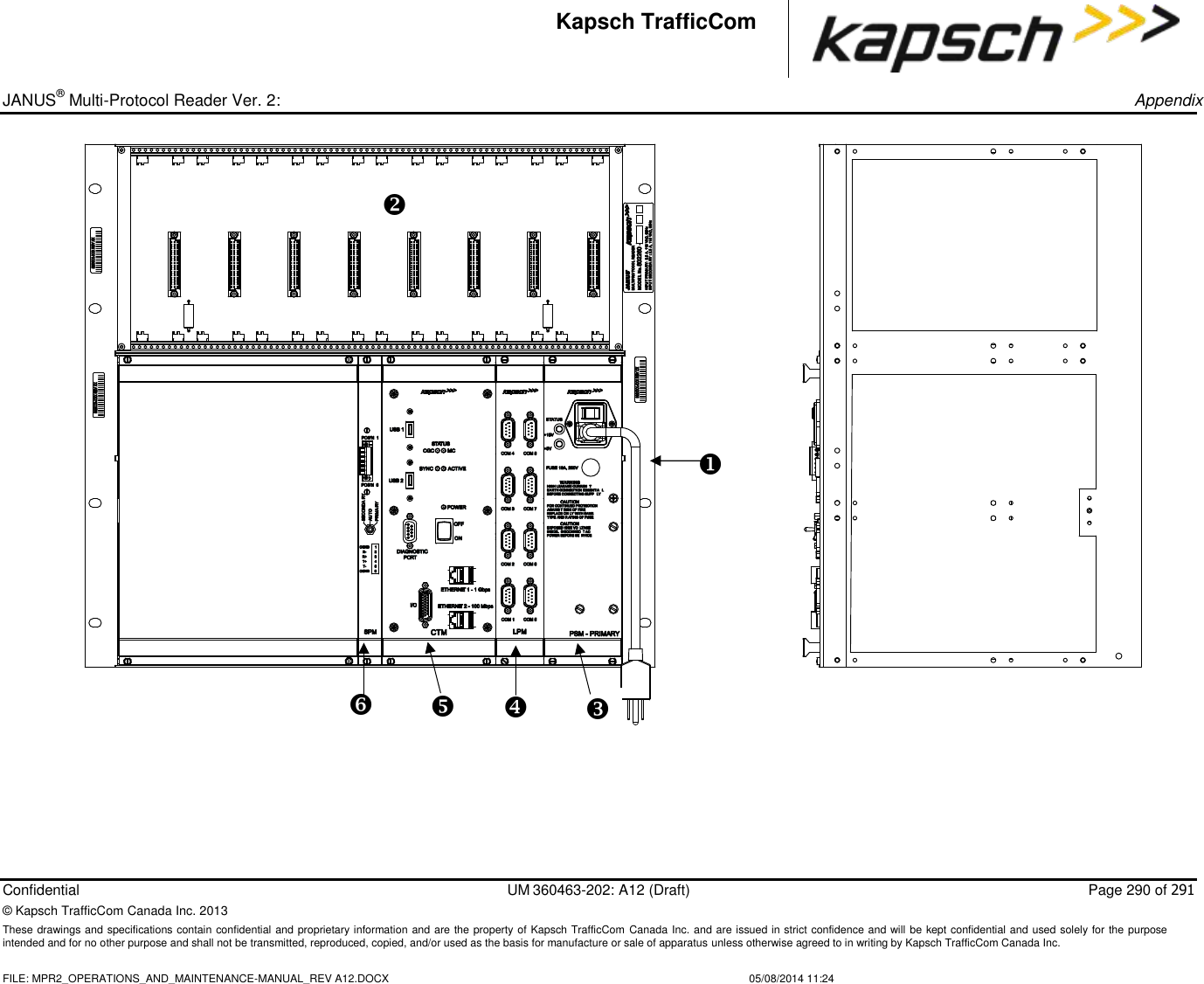
![_ JANUS® Multi-Protocol Reader Ver. 2: Appendix Confidential UM 360463-202: A12 (Draft) Page 273 of 291 © Kapsch TrafficCom Canada Inc. 2013 These drawings and specifications contain confidential and proprietary information and are the property of Kapsch TrafficCom Canada Inc. and are issued in strict confidence and will be kept confidential and used solely for the purpose intended and for no other purpose and shall not be transmitted, reproduced, copied, and/or used as the basis for manufacture or sale of apparatus unless otherwise agreed to in writing by Kapsch TrafficCom Canada Inc. FILE: MPR2_OPERATIONS_AND_MAINTENANCE-MANUAL_REV A12.DOCX 05/08/2014 11:24 Kapsch TrafficCom Terminal Block Temperature and Environmental: as required for operating environment Number of terminals: [4 X (number of Readers in the sync group) plus 4] e.g. 3 Readers require (4x3)+4 = 16 Connection: See the example diagram of a three-Reader sync hub connection inFigure 5-9, page 159. Spares and Tools The following table lists the recommended spares for the JANUS reader and the Lane Kits. Part Number Description 801638-001 Configuration module - CFM 801701-003 Lane port module, RS422 - LPM 801701-002 Lane port module, RS232 - LPM 802311-001 Power supply module, primary - PSM 802311-002 Power supply module, secondary - PSM 307865-020 Fuse, time lag, 10A, 500V, power supply main input 801693-001 Sync port module, 2-wire RS485-SPM 801693-002 Sync port module, 4-wire RS485 - SPM 801693-003 Sync port module, 4-wire RS422 - SPM 802284-TAB Controller module, RS422 - CTM 802284-TAB Controller module, RS232 - CTM 802344-001 Lane kit, IAG-3 800260-011 Antenna, IAG-1 800260-015 Antenna, IAG-3 800125-001 Adapter cable, RF](https://usermanual.wiki/KAPSCH-TRAFFICCOM-CANADA/802295A.Operations-and-Maintenance-Manual/User-Guide-2263970-Page-273.png)