KODICOM SHR5016 Digital Video Recorder User Manual users manual
KODICOM CO., Ltd. Digital Video Recorder users manual
UserManual.wiki
>
KODICOM
>
SHR5016 User Manual
users manual
Navigation menu
Upload a User Manual
Namespaces
Wiki Guide
HTML
PDF
Info
Views
User Manual
Discussion / Help
Navigation

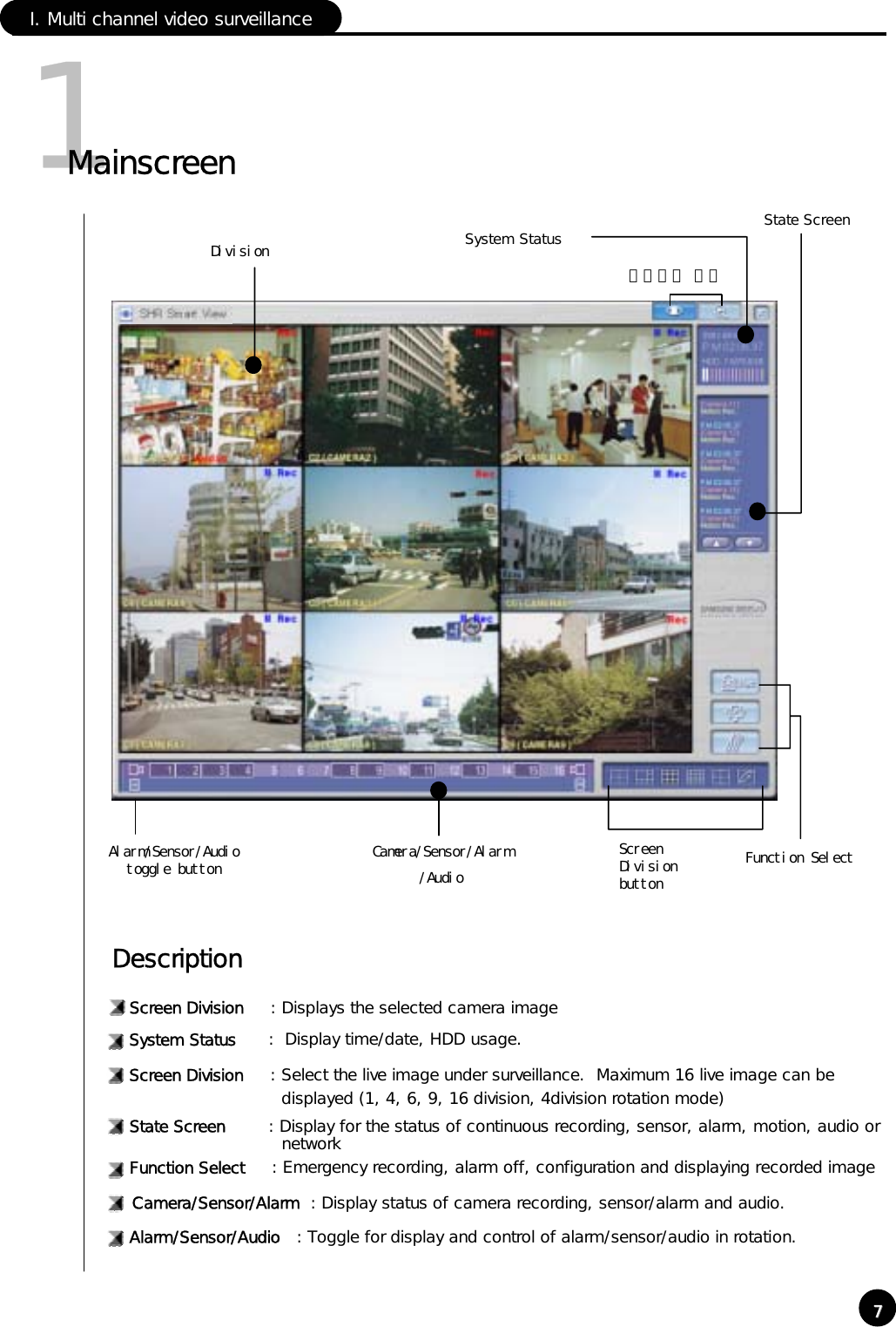
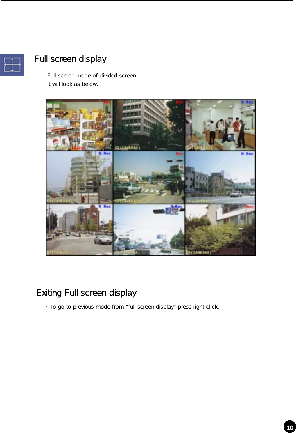
![882Screen DivisionScreen division can be done by 『Screen Division』buttonRECCamera namePAN/TILTPTZ camera display Recording statusScreen DivisionCamera : Display the position of the camera under surveillance.The default value is 1[POSITION1]. But you can modify it in setup.Recording Status : Display recording status of each camera. For continuous recording in red “Rec”, and for motion detection recording in blue “M Rec” and nothing for no recording.PTZ camera display : When the installed camera is PAN/TILT, displays green “ PAN/TILT”](https://usermanual.wiki/KODICOM/SHR5016/User-Guide-271028-Page-9.png)
![17171HardwareⅡ. Environment SetupHardware [Camera]① Press set up button for system setup② Screen to input password will appear for system securing purpose. If the password was not created initially, then just click [ok].](https://usermanual.wiki/KODICOM/SHR5016/User-Guide-271028-Page-18.png)
![1919DescriptionHardware [Sensor] Select Sensor: The number of external sensors and input terminal should be correspondent to each other.▶ NC (Normal Close Type sensor): While on detection mode, choose this when sensor is near the point of contact▶ NO (Normal Open Type sensor): While on detection mode, choose this when sensor’s contract point is open.NC/NO: Configure Sensor Each time when the button is clicked it will change to [NC]<->[NO] and vice versa. (Default is set to [NC])Alarm: While on Sensor detection mode, alarm will be on when sensor activates.Recording time by sensor: When there is a signal from sensor connected to system, this function is to setup time which will record camera’s image linked with sensor.(It can be setup from 1 second to 10 seconds).](https://usermanual.wiki/KODICOM/SHR5016/User-Guide-271028-Page-20.png)
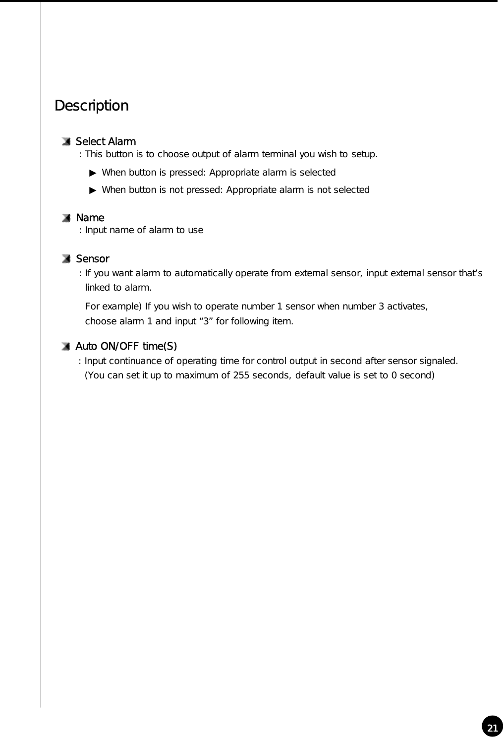
![2020FunctionHardware [Alarm] ・ It indicates whether alarm will be used or not and setup sensor and time of output produced. ・ Output of alarm will be either ON/OFF when any sensor or moving object is captured.It can control light, siren, speaker, and other external equipment.](https://usermanual.wiki/KODICOM/SHR5016/User-Guide-271028-Page-21.png)
![2222DescriptionHardware [External monitor] External monitor function produces output for image from DVR using analogue monitor (TV). Select Camera: Choose the camera which will produce output by external monitorThe output will be automatically produced according to setup timeDescriptionSelect time(S): The output from external monitor should be assigned in second (From 1 sec to 10 sec)▶ When button is pressed: Appropriate camera is selected▶ When button is not pressed: Appropriate camera is not selected](https://usermanual.wiki/KODICOM/SHR5016/User-Guide-271028-Page-23.png)
![23232SystemSystem [System information] Site code: Default is set to 100-001 The value may change at your discretion but anything must be inputted.Description☞ When connecting from Center to Site, it simultaneously searches and compares site Code and password. If either site code or password is wrong, then the connection will not be made.Location: Input name of place where system is installedModel: Contains information of programDistributor: Input name of installer](https://usermanual.wiki/KODICOM/SHR5016/User-Guide-271028-Page-24.png)
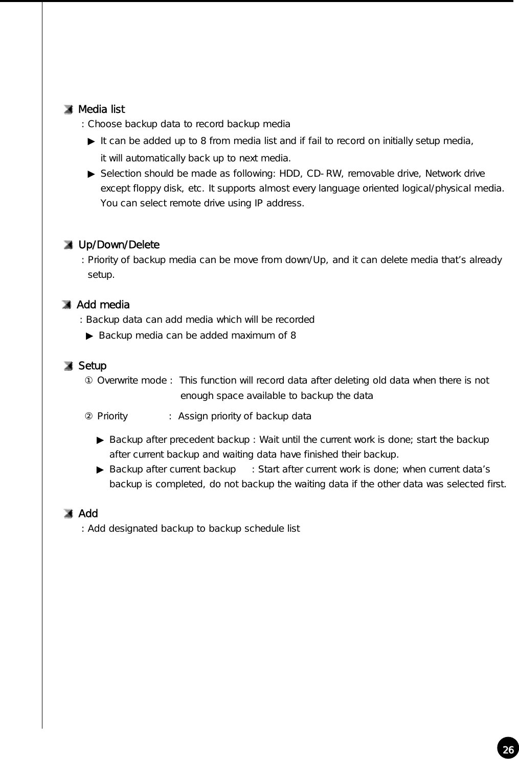
![2424System [Backup setup] Backup schedule setup・ This backup media will show reserved list of backup data which will record data, assigned timefor backup, and etc.・ According to assigned backup schedule, it will backup in order.DescriptionCalendar・ Calendar will appear in Pull-down type like picture above when you click on [>] button indicated beside the current date.You can check backup schedule list assigned by days and current date will be displayed if youclick “Today”.Add: It adds assigned and rotation time of backup schedule data and data to be recorded inbackup media.Delete: It deletes reserved category from backup schedule setup. Setup: If [Setup] is not selected, reserved information will not be stored from backup schedule list.](https://usermanual.wiki/KODICOM/SHR5016/User-Guide-271028-Page-25.png)
![2525Title: Input name to be add on backup schedule list Date/Time: Selects start and end time for backup data▶ It must be setup after current recording time.▶ If it was setup before current recording time, then it will be ignored and won’t be added tothe list when [Add] button is clicked.Method to add backup scheduleBackup start time interval after: After backup data has finish its recording, it assigns when the backup will start after data has finished its backup. ▶ Possible select time will be from 1 to 4 hoursRotate option: Repetitive rotation cycle can be maintained by assigning assigned date and Year/Month/Week/None basis for backup data ▶ If [None] is selected, only one day setup can be made for assigned date/time.](https://usermanual.wiki/KODICOM/SHR5016/User-Guide-271028-Page-26.png)
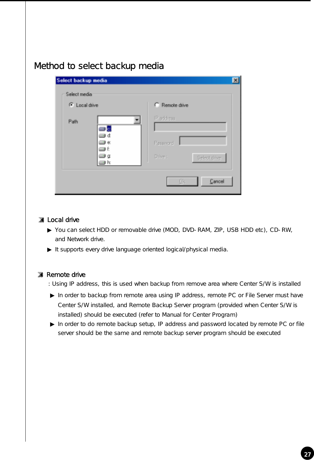
![2828Select drive: Input IP address and password and select [Select Drive]. ▶ In order to connect to Remote backup server for remote backup, remote IP address andregistered password from Remote Backup server program is needed. (If password is not registered,select [Select drive] button after IP address from remote siteis inputted.)Drive path: If connection is made successfully using selected IP address and password, you may choosean appropriate backup media drive from remote PC or File server.Remote drive](https://usermanual.wiki/KODICOM/SHR5016/User-Guide-271028-Page-29.png)
![2929Connection Fail: If selected IP address and password is different or Remote Backup Server program has notbeen executed from remote PC or File Server, then connection will fail and you may not beable to choose backup media drive. Backup: While backup is progressing, animated icon will appear on top of screen. When you double click on it, you can check on current data’s backup progressing process and waitingbackup data list. ▶ Click [Hide]Button to close backup window Indication of Backup status](https://usermanual.wiki/KODICOM/SHR5016/User-Guide-271028-Page-30.png)
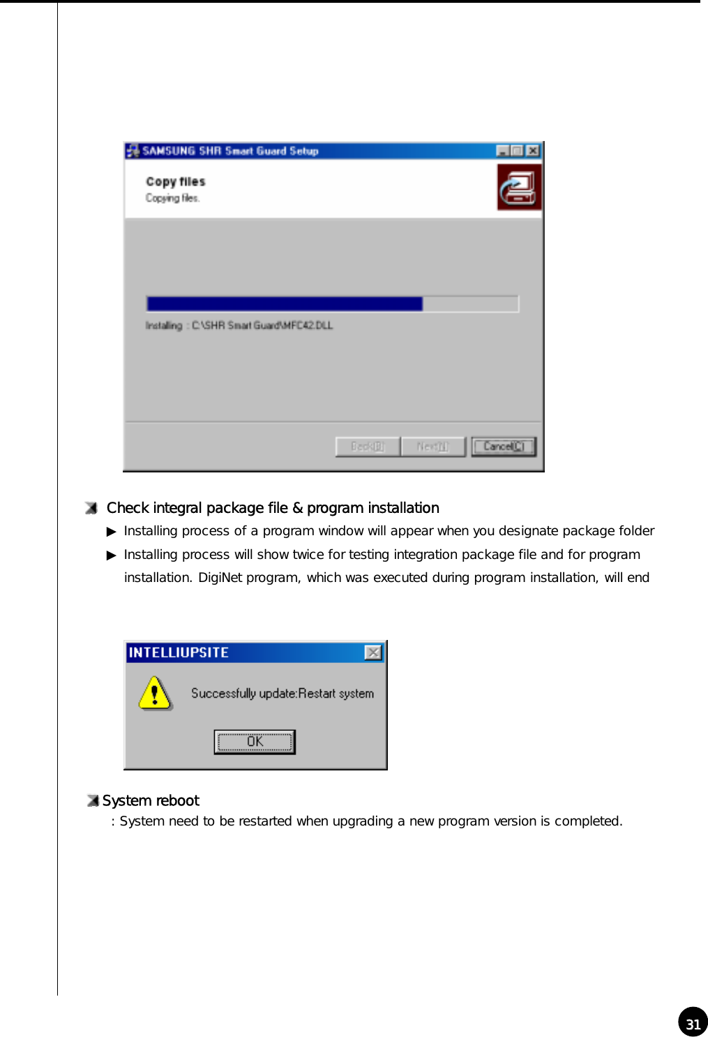
![3030System [Quick] Select Package directory▶ Click [OK] after selecting hard disk or joint network folder which is store in a new version ▶ Appropriate folder must include package folder(Data1, Data2, Data3, Data-a, Data-b, etc.)or all files from package folder must be included in one folder.DescriptionDescriptionWhen [Quick] is selected, Intelli Upgrade window will be executed to let you choose new package for program version. This function is to upgrade to a new version that’s stored in hard disk or joint network folder.☞When upgrading to a new version using Intelli Upgrade, upgrading does not support floppy diskette. Therefore, we recommend you to upgrade after copying the whole media or on a hard diskette. ☞If there is no file or package folder in certain folder due to a wrong folder designation, or if the damage had occur to the file, then it will not be considered as a normal package so the program will not upgrade normally.](https://usermanual.wiki/KODICOM/SHR5016/User-Guide-271028-Page-31.png)
![3232System [Other] DescriptionVideo Format: Choose either NTSC or PALDisplay setup: It sets up status bar appeared from surveillance screen or area▶ When button is pressed: Appropriate status bar or area appears from detection mode ▶ When button is not pressed: Appropriate status bar or area don’t appear from detectionmode ☞ In order to find out the status of Audio, Sensor, Alarm의 Status bar, click (audio/sensor/ alarm button) from lower part of the screen.Set quad rotation time: setup the rotation time in sec to display in 4ch display](https://usermanual.wiki/KODICOM/SHR5016/User-Guide-271028-Page-33.png)
![3333Storage setup: This function modifies possible disk space of data and allocation status for each drive ▶ Window below appears when [HDD Information] is clicked ① Drive allocation▶ Displays Allocation of HDD▶ Currently available disk space for each drive and allocation status can be checked②Modify storage structure▶ You can modify the allocation on each drive▶ You can re-allocate DB setup for each drive by clicking [Modify storage structure].](https://usermanual.wiki/KODICOM/SHR5016/User-Guide-271028-Page-34.png)
![3434☞[Note] What is WaterMark ?BMP and JPEG images can be modified anytime by user. To ensure the original image which can be modified, special protection called ‘watermarking’ is enabled onto the image. Any changes to an original image, including just one pixel, will inform you that the image has been modified.When recorded image was modified from DigiNet program, WaterMark authentication and WaterMark check will tell you whether the image was modified or not.Watermark setup▶Using watermark ① This function inserts Watermark authentication mark on image to be recorded.② When this function is selected, image will indicate WaterMark on the image.▶ Displaying watermark text① This function inserts Watermark authentication mark on image to be searched② When this function is selected, image will indicate WaterMark onthe image.System Restart time: setup the automatic rebooting time for everyday.(This is used to make system more stable.)▶ Default setup is “Used”, in order to disable this click “Used” button again. It will change to “No Use”](https://usermanual.wiki/KODICOM/SHR5016/User-Guide-271028-Page-35.png)
![35353Camera/Audio recordCamera/Audio record Select Camera: It indicates selected camera under Hardware[Camera] and camera that’s currently in recordingis selected above.DescriptionRecording frame rate per camera: Number of frames to be recorded are adjustable by each camera ▶ Put your cursor on scroll button and left click on it then choose the amount of time to record (Recording time will be indicated in numbers on the right side)▶ If you increase the recording time from the default setting, then availability of other cameras’recording time will reduce.▶ It could be more efficient to increase the recording time for places where it requires more security.](https://usermanual.wiki/KODICOM/SHR5016/User-Guide-271028-Page-36.png)
![3636Audio: Decided to record audio for appropriate camera ① When REC button is pressed: It records voice for appropriate camera.② When REC button is not pressed: It does not record the voice for appropriate camera.▶ You can setup voice for specific camera and it records with voice signal that is being inputted to microphone terminal. ▶ Voice is recorded according to recorded time for image and the sound data will be recorded when the video signal start its recording. Therefore, sound data will not be recorded if the video data was not recorded. ▶ In order to record voice, system must be installed with sound card or exclusive audio board. (If Sound card or audio board is not installed, you can’t setup audio category and it will be ignored).▶ Only 1 channel can record voice when using sound card installed on main board. Voice recording is supported up to 8 channel when using Samsung made exclusive audio board.▶ If sound card and exclusive audio board are installed simultaneously, then we recommend you to record voice using audio board. [Tip] ・ When trying to backup already recorded data, it can backup with voice and it is possible torecord in specific drive. (But, if the voice data was recorded using audio board then backup cannot be made and it will be supported from later version. ・ If sound card is embedded, 2way audio communication is possible to communicate with S/W. ・ If 2way audio is connected using sound card, audio recording will discontinue. ・ Window must be setup separately for sound card when using 2way audio with sound card.☞Screen size: Choose screen size▶ Basically, resolution for 320*240 is best suitable for file size(display and recording speed will improve twice when resolution is set to 160*120 but it will decrease image quality. 640*480 resolution will give you excellent image quality but recordingspeed will be decreased). ▶ Default value is 320*240 .Quality:To setup image quality▶ Higher value gives higher image quality but file size for per frame will increase. ▶ Default value is set to ‘Normal’☞Image size and compressed image is closely connected for the file size to be recorded.](https://usermanual.wiki/KODICOM/SHR5016/User-Guide-271028-Page-37.png)
![37374ScheduleSchedule Select Camera: Choose camera number to useDescriptionSetup Recording time: This function is to set recording type for selected camera by each day and time. ▶ Select time of day and drag it to select area and then select recording mode form [Record Mode] (C/M/S/P) ▶ If you need to set in minutes, double click on appropriate time then it will be set in minute.Í01 ~ 59 minutes ÎCopy to All: Information of currently selected camera will be copied and applied to every camera at once](https://usermanual.wiki/KODICOM/SHR5016/User-Guide-271028-Page-38.png)
![3838Record mode (C/M/S/P): This function is to set recording type with day and time for selected camera.▶ After choosing day and time from selected camera, selecting more than 1 record mode will change selected time within selected time.▶ If you erase all the record type from [Record Mode], selected setup time will change to no record mode.▶ Default is ‘Motion & sensor record’ of 24 hour continuous record.[Tip] ① Continuous Record- This is used when continuous recording is done without using motion detection.② Motion detection record- This is used when recording is done using motion detection.③ Sensor Record- This function is to record by inputted sensor signal.- Sensor setup can be done by camera and use time. If sensor is captured within selected time, related camera image will be recorded or related control will operate. - Sensor input signal will be ignored if anything occurs outside the setup time.- If related camera or time line is set to ‘Continuous Record’, then Sensor Record cannotbe used. ④Pre Alarm- When a motion is captured on camera, then camera will record every moment of motionoccurrence in addition to five seconds before the motion was detected. (But, recording speed may decrease if you setup several cameras with it).- If the appropriate camera or time is set to ‘Continuous Record’ you cannot use Pre Alarm function.☞•C : Continuous record•M : Motion record•S : sensor record•P : free-alarm record•no record•continuous record•motion record•sensor record•motion and sensor record•motion & free alarm record•sensor & free alarm record•motion &sensor & free alarm recordSupported record typeIndication by record type](https://usermanual.wiki/KODICOM/SHR5016/User-Guide-271028-Page-39.png)
![3939Simple mode: This function lets you to select by minutes instead of hours depend on recording mode. ▶ When [Simple mode] is selected it will convert to [Advanced mode]and gives more optionto setup time. You can set different time for each time. Set holiday: You can pick any specific day of the year and set it as holiday!![Warning]You must select [Save] button from [Schedule setup] in order to store information on any changed holiday.Setup HolidayCalendar: Select any day to designate as holiday▶ << : Move to prior month▶ >> : Move to next month▶ Today : Shows current Month/Day/Year](https://usermanual.wiki/KODICOM/SHR5016/User-Guide-271028-Page-40.png)
![4040Rotate: You may choose specific Month/Day/Year as holiday ▶ If you select [None], one day will be assigned and for that specific day only.Holiday list: This function is to show designated holiday and its repeated date or period in a list ▶ Any additional holidays will be stored in the list in an alphabetical order. Add: This function is to add holiday you have designated.▶ Designated holiday will be added to [Holiday list] when you click [add].Delete: This function is to delete stored holiday.▶ In order to do this, select the date you wish to delete from [Holiday list] and click [delete].](https://usermanual.wiki/KODICOM/SHR5016/User-Guide-271028-Page-41.png)
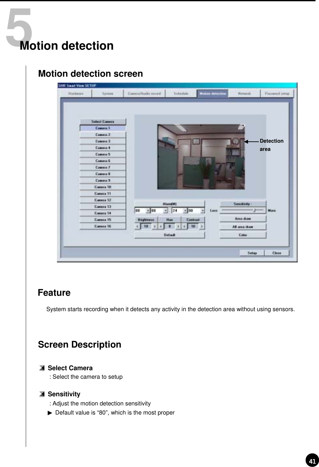
![4242Motion Detection Area▶Select the camera number and draw detection area using left click dragging.▶Maximum five detection area can be made.▶To remove the selected motion detection area drag mouse pointer toward out of box.Area draw▶ Entire area will be under motion detection mode when you click on [Area draw] button.Default▶Restore the default color configuration for the camera by clicking [Default] buttonAlarm(M): System makes beeping sound to alert when there is any activity in the selected time.▶When Alarm(M) button is pressed on : Alarm beeping works.▶When Alarm(M) button is not pressed on : Alarm beeping does not work.☞System beeps only when activity is detected in the selected time zone in recording schedule.☞System does not beep if the camera is set to ‘continuous recording’Brightness / Hue / Contrast: Adjust Brightness, hue,and contrast▶Default for camera is ‘18 / 8 /10’ , and the range is -127~126 and adjustable to each camera. (Proper setup is required depending on site situation)All area draw▶ Entire area for every camera will be under motion detection mode when you click on[All area draw] button.Color▶ If appropriate camera is black and white according to each camera number, then click to convert it to Black and White camera (Default is set to Color).](https://usermanual.wiki/KODICOM/SHR5016/User-Guide-271028-Page-43.png)
![43436NetworkNetworkSensor for emergency: If the sensor detects any signal it sends alarm to Center with the recorded image during the designated time.▶Click the sensor number to configureFeatureEmergency phone numbers: When the first trial fails to connect, it tries to connect to the second number which is emergency phone number. This is to transmit emergency image or message.▶Select [Emergency phone numbers] button and input emergency phone number. Up to two emergency phone number can be used.감지범위Emergency IP address: Transmit emergency image or message by connecting to the assigned IP address.▶Click [Emergency IP address] button and input IP address.](https://usermanual.wiki/KODICOM/SHR5016/User-Guide-271028-Page-44.png)
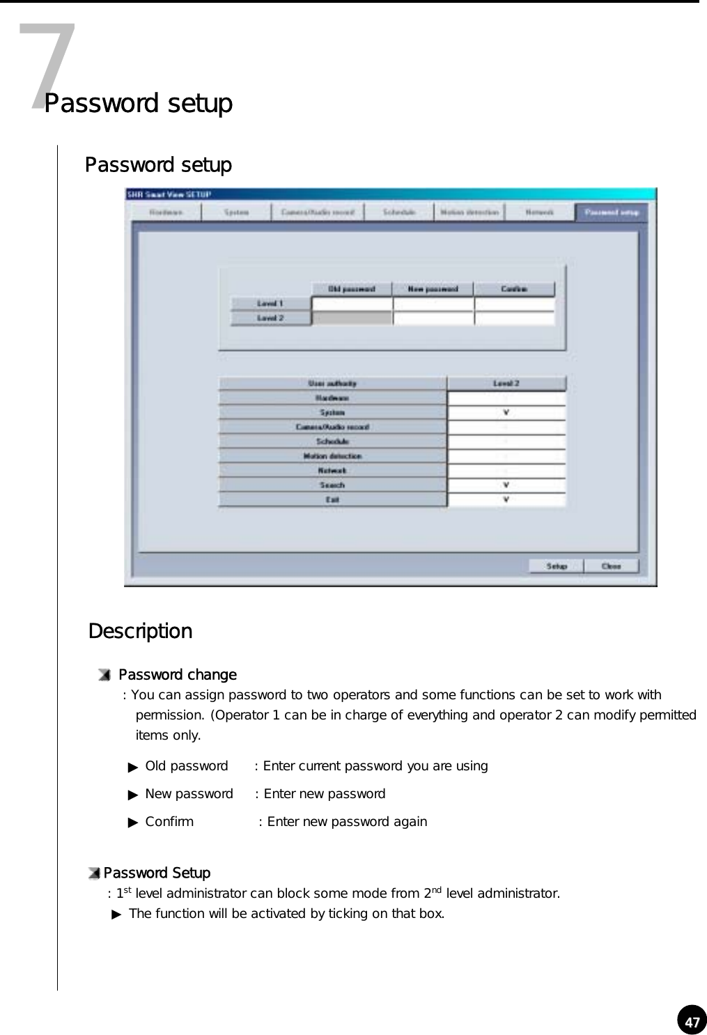
![4444Transfer time: Select the duration in sec how long it will send images to Center on connection.▶If any new signal is detected while connection, image transfer time starts again.☞[Notice]When you try to connect to site from Center, DigiNet checks the site code and password together.Type of connection▶For remote connection LAN, PSTN, ISDN, Leased Circuit can be used.▶ISDN or Leased Circuit using router can be used. ISDN or PSTN can be used to connect to DVR without router directly.▶Check on “No Use” for no connectionPassword: Input required password to connect from Center p.c. (4 digit number is possible.)[Password] : Input password required to access to DVR from Center.[Confirm] : Input once again to confirm.▶Default value is “1234”](https://usermanual.wiki/KODICOM/SHR5016/User-Guide-271028-Page-45.png)
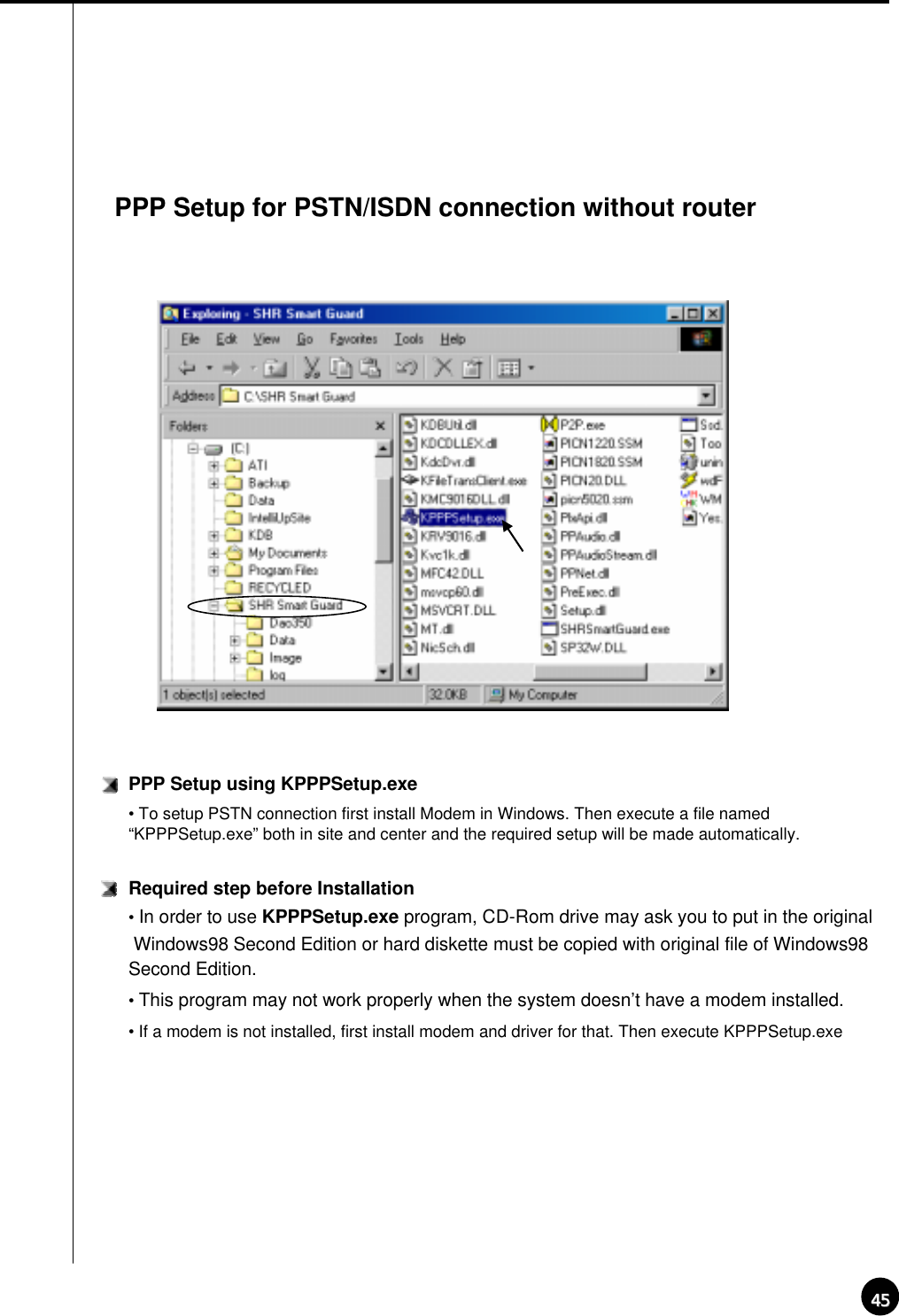
![4646PSTN or ISDN setup on Windows98①Install a modem for PSTN connection and ISDN Terminal Adapter for ISDN connection.②Execute KPPPSetup.exe③Reboot system after PPP setup is done.※Please check the connection between Center and Site after rebooting the system.☞[Notice]• The system may request you original Windows98SE CD, then assign the path of Windows98SE.• For ISDN connection without router, follow the same step as required on PSTN. In other words, just execute KPPPSetup.exeItems that will be installed by KPPPSetup.exe• Dial-up Networking• Dial-Up server• Phone Dialer• Dial-Up Adapter• TCP/IP Protocol• Modification in Dial-up Server propertiesNotice• Any windows of ‘Network Properties’ or ‘Dial-up Server properties’‘ should be closed before running KPPPSetup.exe• Do not execute KPPPSetup.exe twice at one time.(Please wait until you see a message saying the system will reboot.)• Select ‘LAN’ on ‘Communication Setup’ in Site software and select ‘PSTN/ISDN(No Router) in Centersoftware.• KPPPSetup.exe should be installed on both Site and Center.](https://usermanual.wiki/KODICOM/SHR5016/User-Guide-271028-Page-47.png)

![49491Execute Search ProgramIII. Search ScreenSearch Screen① Click on search button to execute from surveillance screen. ② Password screen will appear for securing purposeClick [OK] if the password was not initially entered FunctionConvert to surveillance mode CalendarSearch WindowButtonScroll for Camera Camera Record Storage Time indication and Expansion for graph area Organization of Search Screen ▶ Search screen Window▶ Calendar which shows recording date ▶ Scroll to choose cameras to search, Camera Button▶ Recording type and graph indication of storage ▶ Time indication and Expansion of graph area▶Button for search screen▶ Conversion to Search screen▶ Screen DivisionScreen division](https://usermanual.wiki/KODICOM/SHR5016/User-Guide-271028-Page-50.png)
![50502Search Date and Time Selection CalendarSearch ‘Date’: Choose the Date you wish to search ▶ << : It shows whole calendar >> : Calendar shows the following month ▶ On calendar, it will be indicated in yellow if anything is recorded on such date, red indicationmeans the one you clicked to search, and sky blue indicates that something is being recorded. Time indication and expansion of Graph region: It indicates time for the part where data is recorded.▶ When you click on time, time zone will be expanded in three steps so graph region can beenseen more clearly.▶ In case such country is applied with Summer Time, color will convert from Yellow (default color) to pink but it will convert back to Yellow as soon as the Summer Time is over. ▶ Any modification of time caused by Summer Time will automatically change back to current(actual) time.Time indication and Expansion of graph region ☞ [Tip] What is Summer Time...Sun rises early but sets late during summer so people tend to take advantage for this longest period of daytime of the year by forwarding one hour which is known as Summer Time. Summer time is widely used throughout the world and people forward one hour earlier than actual time at the beginning and do the vice-versa at the end of Summer Time. For example, if the starting time is 2 o’clock then you are to change the time to 3 o’clock and then change 3 o’clock back to 2 at the end.](https://usermanual.wiki/KODICOM/SHR5016/User-Guide-271028-Page-51.png)
![51513Select CameraSelect CameraCamera Scroll button : This function is to scroll search button from up and down.DescriptionCamera : Choose the camera number you wish to search ▶ When you double click on camera number, button and the colored graph of appropriatecamera number will be changed. Indication of stored amount: It indicates record type and storage amount by time.▶ Violet graph – Recorded with continuous recordingBlue Graph – Recorded with motion recordingRed Graph – Recorded with Sensor recordingGreen graph – Recorded with Pre Alarm, but there is no indication if nothing was recorded. Search Bar : This function indicates current time line of data which is being searched. ▶ You can immediately search for any recorded data by horizontally moving search bar. ☞[Note]Black screen will be displayed if there is no image for the camera you selected.❶❷❸❹❶❷❸❹](https://usermanual.wiki/KODICOM/SHR5016/User-Guide-271028-Page-52.png)
![5353Bookmark: Records the location of image under playbackYou can go back to the recorded location directly next time.Time Information: Display time of bookmarked image.▶When you add the image location during search the date and time will be saved in the order by date and time.Description: You can input description on the bookmarked image.▶If you do not input description the one in [time Information] will be input.Add: This is to add the image location to the bookmark list.▶[Add] If you click [Add] button, the current image location will be added to the bookmark.Delete: This is to delete the bookmarked location.▶In order to delete bookmarked record select it in the bookmark and click [Delete]](https://usermanual.wiki/KODICOM/SHR5016/User-Guide-271028-Page-54.png)
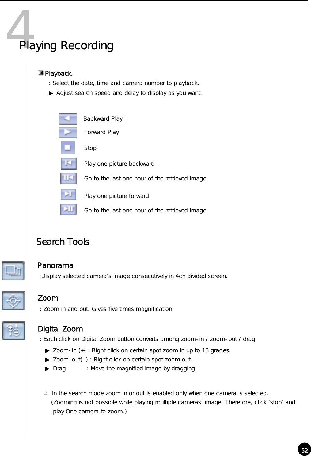
![5454Delete all: Delete all the bookmarked image location.▶ All the image location will be deleted if you click [Delete all] button.Goto: You can go to bookmarked image location by clicking this button.▶ Click [goto] button to go to the bookmarked location after selecting the bookmark.OK: Select [OK] button after adjusting bookmark information.Recording during playback: Image search speed will increase if DVR does not record while searching.▶ In order to set it as recording during playback, click this button again.(This will be disabled in monitoring mode.)☞☞[Notice]Though the image recording goes on while searching, however, recording graph does not change. You should go to live mode and come back to searching mode to see updated graph.Search Speed: Playback skipping the certain number of image.▶ The number is not the number of actual image, but the one set inside Site program.Display Delay: Time to display one image on screen.▶ 0 (Fastest) ~ 50 (Slowest)Screen Division: Playback recorded image in division.▶ 4ch,9ch,16ch can be selected and deactivated mode cannot be used..(8ch DVR supports only 4 and 9 division mode.)](https://usermanual.wiki/KODICOM/SHR5016/User-Guide-271028-Page-55.png)
![55555Search ToolBrightness: Adjust brightness of the image.Contrast: Adjust contrast of the image.Smooth & Sharpness: Make the rough image smooth and vague image clear.Noise Reduction: Reduce noise in the image.Turning image: Turn the image in the angle of 90, 180 or 270. And flipping is possible.Restoration: Getting back to the original image before modification by search tools.☞ [Notice]Search tools an be used for one camera’s image only. Therefore, you should click stop buttonand choose one image to use above tools.](https://usermanual.wiki/KODICOM/SHR5016/User-Guide-271028-Page-56.png)
![56566Audio SetupAudio playback setup: Playback with recorded audio.▶Click on left button creates “Audio Play” window as below.▶ Tick on the box next to “Enable” in “Audio Play” window.▶ Adjust volume properly.[Notice]・Audio can be played only on one selected channel. You cannot play audio watching more than 2channels. You should choose one channel to play audio.・Video loss can take place within the first 1~3 seconds of play back, this is due to the video and audio synchronization and is not a fault・Audio can only be played back in normal forward play. Reverse Play or Frame Play is not possible・Skip and delay cannot be used with audio play back.・ Please refer to 『Appendix』for audio setup.☞](https://usermanual.wiki/KODICOM/SHR5016/User-Guide-271028-Page-57.png)
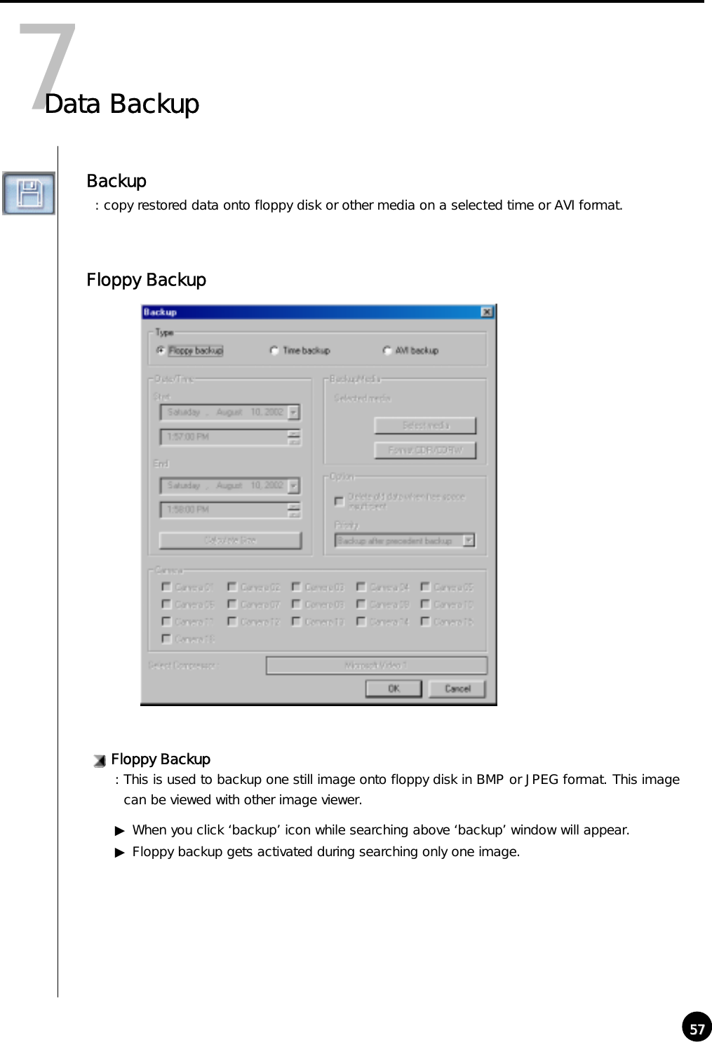
![5858Floppy Backup①Click [Floppy Backup] in “Backup” window and click [OK]②Below ‘watermark checking’ window appears.☞[Notice]The image will be copied onto Floppy diskette in BMP or JPG format. The image will be copied with the ‘watermark checker program’ to check to see whether the image was illegally modified or not.③If you click ‘Yes’, the selected image will be copied onto floppy disk with Watermark checkingprogram.▶Only one image can be copied in floppy disk backup and ‘watermark’ checking program willbe copied only at the first copying.](https://usermanual.wiki/KODICOM/SHR5016/User-Guide-271028-Page-59.png)
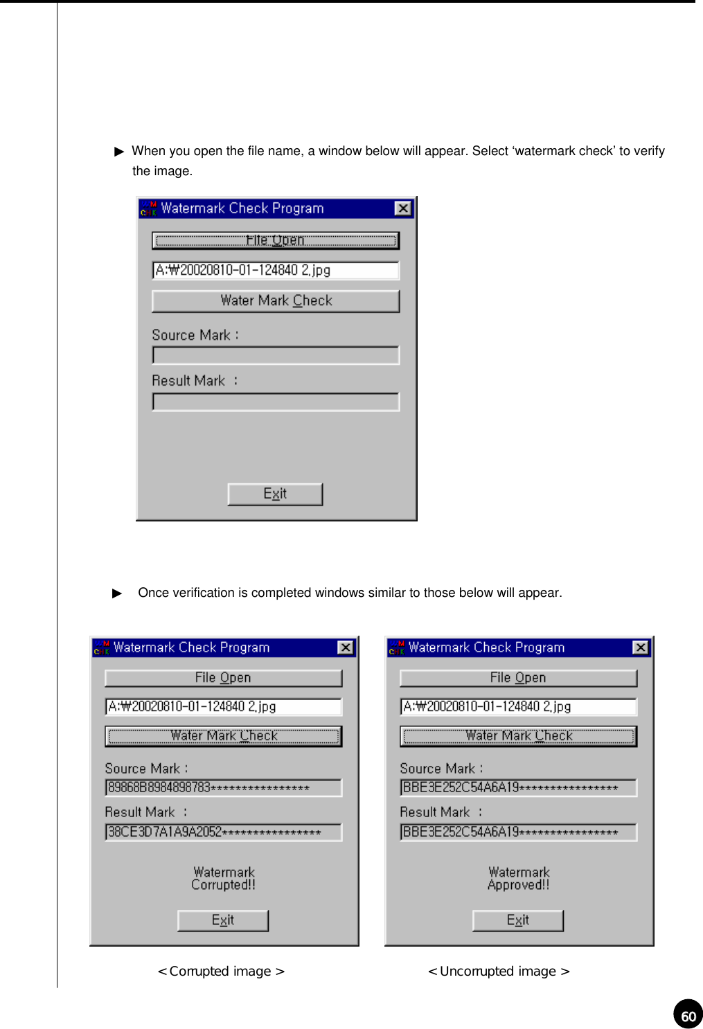
![5959Watermark Check Program▶If you execute ‘WMChecker.exe’ which is copied to the Floppy Disk with the backup image, following ‘WaterMark’ checking program appears.▶If you click ‘File Open’ button, below widow will appear to check an authentication of the image[ How to use Watermark Checker ]: You can check the authentication of the image restored in BMP or JPG.](https://usermanual.wiki/KODICOM/SHR5016/User-Guide-271028-Page-60.png)
![6161Time backup (Large Media): This is a backup using other than floppy such as HDD, CD-RW, mobile driver, network driver or copy using IP address.Backup by time▶ This streaming data is our own data type. So this image cannot be read using other programthan SAMSUNG Center program. Date/Time: Select the time to start and finish backup.▶ This time setup should be earlier than current time. If this is later than current time backup does not work despite clicking [OK]Calculate Size: Click this button to calculate expected data size for the selected time.](https://usermanual.wiki/KODICOM/SHR5016/User-Guide-271028-Page-62.png)
![6262Select media: Media to use on backup.▶You may select HDD, CD-RW, Portable drive, Network Drive, Remote IP Address except floppy diskOption[Delete old data when there is not enough space]: This function will record data after deleting the old data when there is not enough storage spaceto backup the data.[Priority]: Select the priority of backup data.▶Wait until the processing work is done; start the backup after current backup and waiting data have finished their backup.▶Start after the precedent backup; when current data’s backup is completed, do not back up the waiting data if the other data was selected first.OK: Backup will start from the designated backup media drive when you click [OK].Format CDR/CDRW: This is used when you select CD to backup data..▶If CD was not formatted, use Direct CD program for CD formatting process. When you select [Format CDR/CDRW], you can format CDR/CDRW media by Direct CD (Refer to appendix)☞[Notice]Direct CD program has to be installed in window in order to format CD.](https://usermanual.wiki/KODICOM/SHR5016/User-Guide-271028-Page-63.png)
![6363CD-R/RW backup• Select [Select media] from “backup media” window.• From “Select backup media” window, select [OK] button after selecting CD-RW drive which you will backup.• You need to format CD in order to backup CD-R/CD-RW from DigiNet program.• When the CD is unformatted or failed to Backup, please follow this step to Format the CD. (Refer to page 72)• In order to backup on CD-R/CD-RW, Direct CD S/W should be installed on the system.• If the CD is formatted, follow the same way with backup to HDD, or removable drives (DVD-RAM, ZIP, MOD, RB)[ Backup onto CD-R / CD-RW ]](https://usermanual.wiki/KODICOM/SHR5016/User-Guide-271028-Page-64.png)
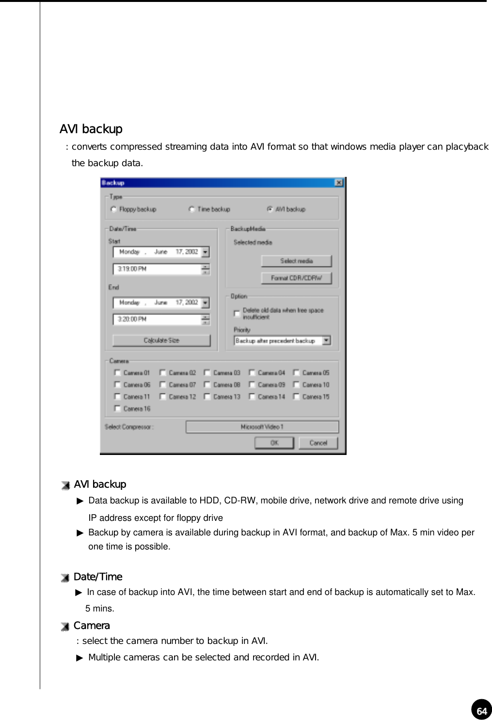
![6565Select Compressor: You can select available compression codec under AVI backup.Format CDR/CDRW: This is used when backup media is CD.▶When CD is not formatted a user should proceed CD format using Direct CD program, and once he chooses [Format CDR/CDRW], Direct CD program begins to format CDR/CDRW media.(refer to appendix)☞[Notice]In order to format CD, DVR should have Direct-CD installed.Select media: Select media type▶HDD, CD-RW, Mobile Driver, or Network driver except floppy disk can be used.• In order to format CD, DVR should have Direct-CD installed.• When other advanced compression codecs then the basic Mpeg compression codec provided on Window were installed, AVI files are saved into smaller sizes, the compression quality is advancedand the time for backup is reduced.• According to types of compression codecs, number of selected cameras and set backup time, AVIbackup time may differ significantly.(When the basic codec provided on Window is used, codecs ofMpeg4 Video Codec v2 over are recommended.)• In case of backup into AVI files, audio data are not backed up but only video data are backed up intoAVI files.• According to the resolution of saved video data, resolutions of AVI files into which the data are backedup are as follows.SAMSUNG Resolution AVI File( NTSC / PAL )640x480(768x576) 320x240320x240(384x288) 160x120(192x144) 160x120☞[Tip]](https://usermanual.wiki/KODICOM/SHR5016/User-Guide-271028-Page-66.png)
![6666[AVI Backup Status]Started: When you double click on animated icon located on top of image while real time isin progress, current backup data and backup status and its progress rate, lapsed time, and remained time can be checked. [AVI Real Time Backup File]Choose AVI Real Time backup file : In order to check AVI Real time backup file, double click on recorded file from assigned drive “KDB\BACKUP_AVI\ {xxxxxxxx-xxxx-xxxx-xxxx-xxxxxxxxxxxx}\month day year-time minsecond ~month day year-time min second[camera No].avi” then you can check appropriate file information using Window Media Player which is separately provided by real time player or window.](https://usermanual.wiki/KODICOM/SHR5016/User-Guide-271028-Page-67.png)
![6767AVI Real Time Backup File and Caption information: Using media player provided from Window, caption information of Date and time, days, camera number and etc can be indicated. Other real time player shows image only. ☞[Note]We recommend minimum of v6.4 for Media Player and if caption information cannot bechecked, then choose ‘Caption’ from [View] to check such information.](https://usermanual.wiki/KODICOM/SHR5016/User-Guide-271028-Page-68.png)
![68688Print Search Screen Print: You can only print when Print button is selected from searched screen while one image is magnified, then click on [OK] button shown below (Size and Brightness must be adjusted in advance).!!Following ERROR will occur if print setup is not completed](https://usermanual.wiki/KODICOM/SHR5016/User-Guide-271028-Page-69.png)
![6969☞[Tip]Print Setup1. Click Start ÆSetup ÆPrint from Windows 982. Double click on ‘Add Printer’ when Print Menu appears 3. Click [Next] when Add Pinter Wizard executes4. Check to see if [Local Printer] is selected and then Click [Next] if Printer is connected to system. 5. Select Print Driver from the box where it asks manufacturer, name, and model of printer. 6. Print setup is completed when Driver is installed on screen. Size of Image Output1. It produces output and the printed size is equivalent to the magnified ones seen from the screen. When printer is not working, 1. Check to see whether printer is setup from Window or not2. If the printer is setup to the system but still not working, then check to see if cable or power code are connected.](https://usermanual.wiki/KODICOM/SHR5016/User-Guide-271028-Page-70.png)

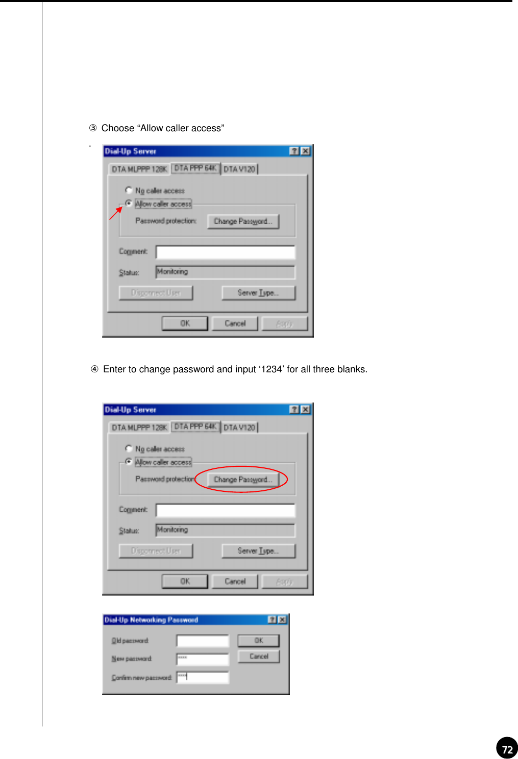
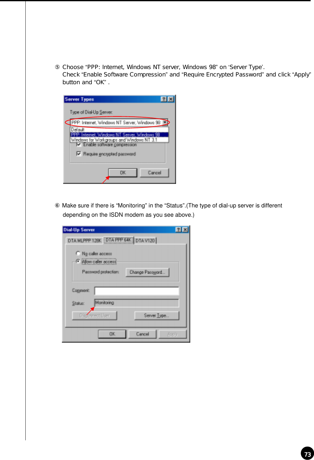
![71711Manual ISDN Setup without routerIV. 부록[When there are a few dial-up servers depending on the ISDN modem]• Basically ISDN setup will be done automatically when you run KPPPSetup.exe. However, there might be cases that you need to setup manually when there are a few dial-up servers depending on the IDSNmodem. In that case, please follow the next step.• When the ISDN modem supports a few dial-up servers, you should select a proper dial-up server that supports ISDN among the dial-up servers.• Above step should be done after executing KPPPSetup.exe.Manual Setup①Select ‘Dial-up networking’ on ‘My Computer’ in background②‘Connections’ Æ‘Dial-Up server’.](https://usermanual.wiki/KODICOM/SHR5016/User-Guide-271028-Page-72.png)
![7474[Notice] connection speedWhen you get disconnected a lot on PSTN or have a bad connection, go to ‘Control Panel” Æ“Modem” Æ“General” Æ‘Properties’.Select ‘38400’ on Maximum speed on “Modem properties” (Select ‘115200’ for ISDN.)To make the connection between Center and Site set ‘Maximum speed’ the same.(Connection might be bad depending on their line status like noise and defective line.)☞☞](https://usermanual.wiki/KODICOM/SHR5016/User-Guide-271028-Page-75.png)
![75752Formatting a CD using Direct CDIV. Appendix[Formatting CD using Direct CD]When you try to backup on an unformatted CD or in case where the message of backup failure has shown, format the CD as follows.※ Below contents is based on Direct CD v5.1. If some other message comes up, please refer to Direct CD manual.CD format and backup① Select [Media Select] button in “Backup Media” -> Select CD-R/RW drive in “Local Drive”-> Click [OK]② Insert empty CD-R/RW media and click [Format CDR/CDRW](If CD-R/RW drive is set as “auto” Direct CD program will run automatically.) ③ Check if CD-R/RW is selected when the Direct CD format utility comes up, Direct CD andclick [format CD]](https://usermanual.wiki/KODICOM/SHR5016/User-Guide-271028-Page-76.png)
![7676⑤ “Formatting CD..” Window will appear and starts CD-R/RW media format.④ When you see a “drive format” window, input a name to “Label”and click [Start Format] button⑥ When the format is done, below window will appear saying “CD Ready”. Then click [OK]](https://usermanual.wiki/KODICOM/SHR5016/User-Guide-271028-Page-77.png)
![7777⑦ If Direct CD format utility windows come up, click this button to close.. ( Do not click [eject] button.)⑧ Select the type, time, and camera for backup and click [OK] button.“WRITE” LED of CD-R/RW will be turned on till CD writing is done. Do not press button in CD-R/RW⑨ Once the backup is done, click “Eject” button in CD-R/RW](https://usermanual.wiki/KODICOM/SHR5016/User-Guide-271028-Page-78.png)
![7878⑩ If “Direct CD Eject Options” window comes up, select “Close to Read on Any Computer” and click ”OK”(If possible select “Protect CD so it cannot be written to again” not to re-write on CD-RW)⑪ Below window will appear to close CD-R/RW media. Wait until this procedure ends.⑫ Once the above procedure ends below window will appear. Then eject the CD-R/RW media and click [OK] button.](https://usermanual.wiki/KODICOM/SHR5016/User-Guide-271028-Page-79.png)
![79793System setup for Audio functionIV. 부록[Audio volume setup for voice recording]Prior to recording voice, you need to first control audio volume for microphone. Go to ‘Start ÆProgram ÆApplication ÆEntertainment ÆVolume Control’Setup① Execute ‘Multimedia’ in Windows control pannel.② Click “Recording” in Multimedia properties by clicking “Recording”button.](https://usermanual.wiki/KODICOM/SHR5016/User-Guide-271028-Page-80.png)
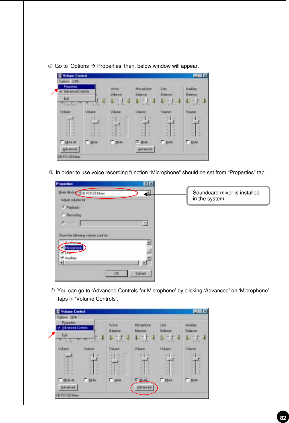
![8080③ If the Recording window appear, go to ‘Option->Properties’④ Select ‘Microphone’ in ‘Properties’ window and click ‘OK’.⑤ If you click [OK] below ‘Microphone balance’ will appear in the ‘volume Control’ window.In order to use voice recording function “Microphone” should be set from “Properties” tap.](https://usermanual.wiki/KODICOM/SHR5016/User-Guide-271028-Page-81.png)
![8181!![Notice]If you don’t tick on the check box of ‘Microphone’, audio recording will not work properly..For proper use of Audio recording and two-way audio function above setting should be made both Center and Site.PC setup for use of Microphone from advanced mode▶ For audio recording following volume setup should be made for microphone.▶When the audio input through microphone is weak even in the maximized volume you can amplify the audio input by adjusting as follows.Setup① Execute ‘volume control’ window by following “control panel-> Multimedia-> properties’](https://usermanual.wiki/KODICOM/SHR5016/User-Guide-271028-Page-82.png)
![8383⑤Please adjust the options to fit into your system and check the sound output from ‘Other Controls’.• Click on ‘Mute’ which is circled on the left picture, if you do not want any voice output from a speaker that was inputted to the microphone but record the voice onlyor if you just want the output of searched voice from the speaker only when installing a microphone. • When the system doesn’t support ‘Microphone Boost’ function, ‘Advanced’ buttonmay not appear. In that case you can solve it by using a more sensitive amplifiedmicrophone.• Sound card must be installed properly to use voice recording function.☞☞[Note]](https://usermanual.wiki/KODICOM/SHR5016/User-Guide-271028-Page-84.png)
![84844Serial cable connection (input)RS-232C PortConnect to COM 1 Port(9 PIN)[Function of RS-232 Serial connection]• Enables Sensor function• Enables Control function• Enables P/T/Z function• Enables Watch Dog function• Enables External monitor output function (Depends on model)[Notice]Serial Cable must appropriately connected to COM1 Port and RS-232 in order to use the function above. Control and Sensor, part of the product which is not supported by P/T/Z may not includeSerial Cable. Connection will be provided only for the product that supports control andsensor. If Serial Cable is not connected appropriately, system may not operate properly and evendamage the system. Also, it may not recovered automatically. (Product which is not supported by Control and Sensor, P/T/Z function uses its own autorecovery function.) !!IV. Appendix](https://usermanual.wiki/KODICOM/SHR5016/User-Guide-271028-Page-85.png)
![85855PAN/TILT Drive connection[Notice]1) Be cautious about (+),(-) of the signal line.Wrong connection of the signal line might cause damage.2) Please contact our distributor if you use other brand’s RX Receiver.RUN LEDEXTERNAL MONITORRS-422 connection(from RX-Receiver)RS-232 Connection(from Com1 port)Remote Controller ReceiverNo UseSIGNAL ( + )SIGNAL ( - )!!IV. Appendix](https://usermanual.wiki/KODICOM/SHR5016/User-Guide-271028-Page-86.png)
![86866External Sensor input and Control output connectionIV. Appendix12345678SENSORGOne line of signal line for sensors such as infrared rays, heat perception, magnetic etc, should be connected to COM connector and the other line is connected to any sensor 1-8 connector which you selected.!![Notice]Please use individual adapter for each sensor’s power input.12345678GCONTROLExternal Power (DC 12V)(-)(+)Alarm, Siren, relay etc.[Notice]The power of adapter should be no more than 12V and 300mA.Additional external relay should be used to control on and off of device powered byAC input.• When the linked connection and control by external sensor works linked control output connects to COM port. (setup->hardware->alarm) Control output related by external sensor☞it remains “NC” condition normally☞but it switches to “NO” when it starts sending control signal!!](https://usermanual.wiki/KODICOM/SHR5016/User-Guide-271028-Page-87.png)
![8787Any defect under normal use within the warranty service period we give you free repair service according to the warranty sheet.We charge you with the fee of parts and service despite free warranty service period.1. Any breakage made without care.2. Breakage or trouble made by natural disaster.3. Breakage or trouble made by breaking the product guide or manual.4. Breakage or trouble made by wrong power voltage or frequency.5. When you want to reassemble for full system or replace parts within warranty service period.6. When unauthorized engineer modified or made damage on the product trying to repair it, we may charge ]you with the fee.We don’t support the breakage after warranty service period. If the customer wants to get it repaired, we charge them with the fee.¾This warranty sheet may not be provided again.¾Please get this sheet filled when you purchase the product.¾You should show this warranty service sheet when you get a warranty service.Warranty GuideWarranty GuideAddressNameCustomer1 year from the purchasing dateWarranty PeriodDate you purchasedDistributorProduct Serial NumberProduct & model nameProduct Warranty Service SheetThis product has passed thorough quality control and test, and if this get broken during normal use we provide 12 months warranty service.Warranty GuideCheck this warranty sheet first.Please contact the distributor after checking out any defect in the product. The standard for repairing, replacement or reimbursement follows CustomerWarranty Content](https://usermanual.wiki/KODICOM/SHR5016/User-Guide-271028-Page-88.png)