Kelvin Hughes DTX-A3-FDLR X BAND RADAR User Manual
Kelvin Hughes Limited X BAND RADAR
UserManual.wiki
>
Kelvin Hughes
>
DTX A3 FDLR User Manual
User Manual
Navigation menu
Upload a User Manual
Namespaces
Wiki Guide
HTML
PDF
Info
Views
User Manual
Discussion / Help
Navigation


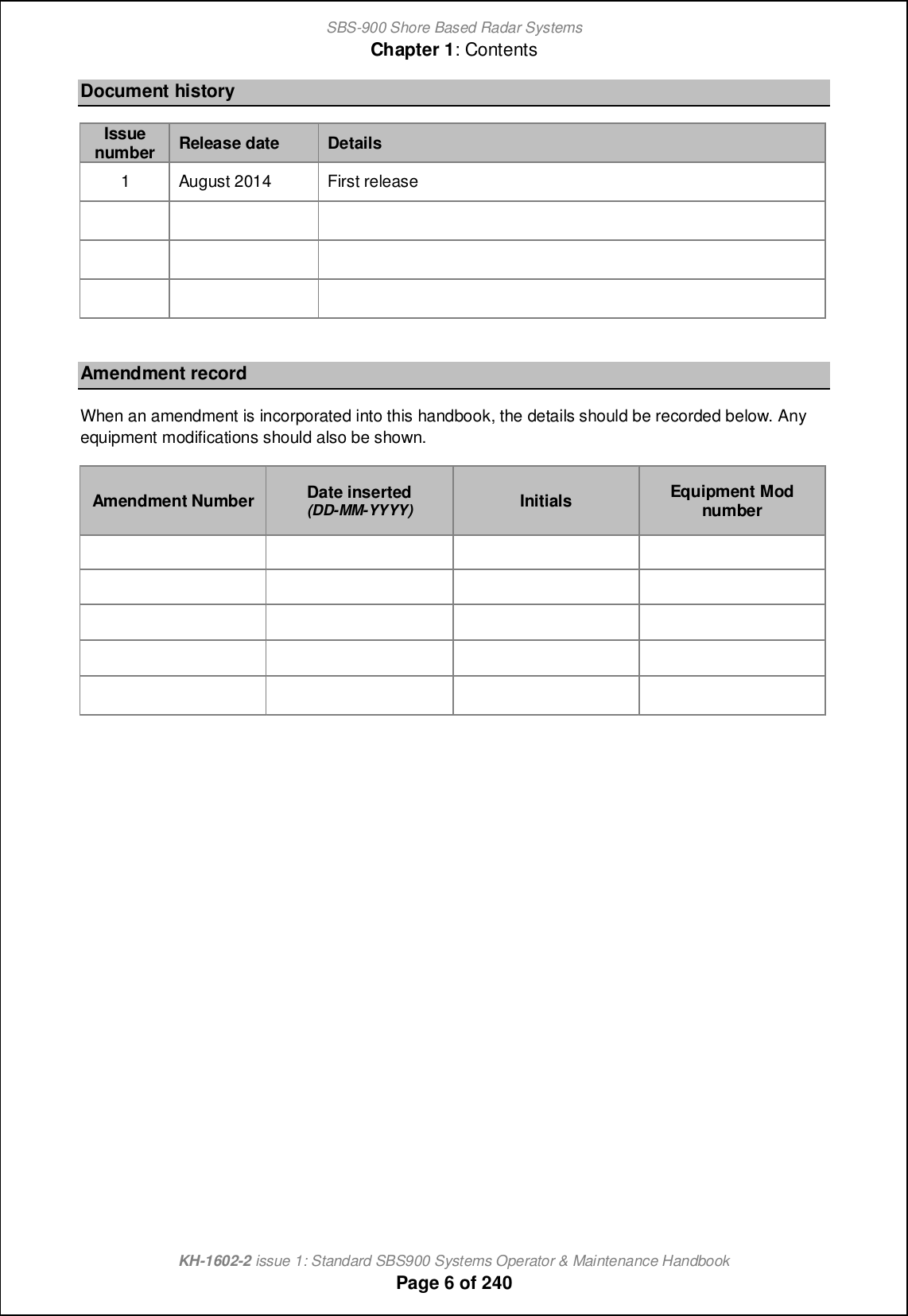
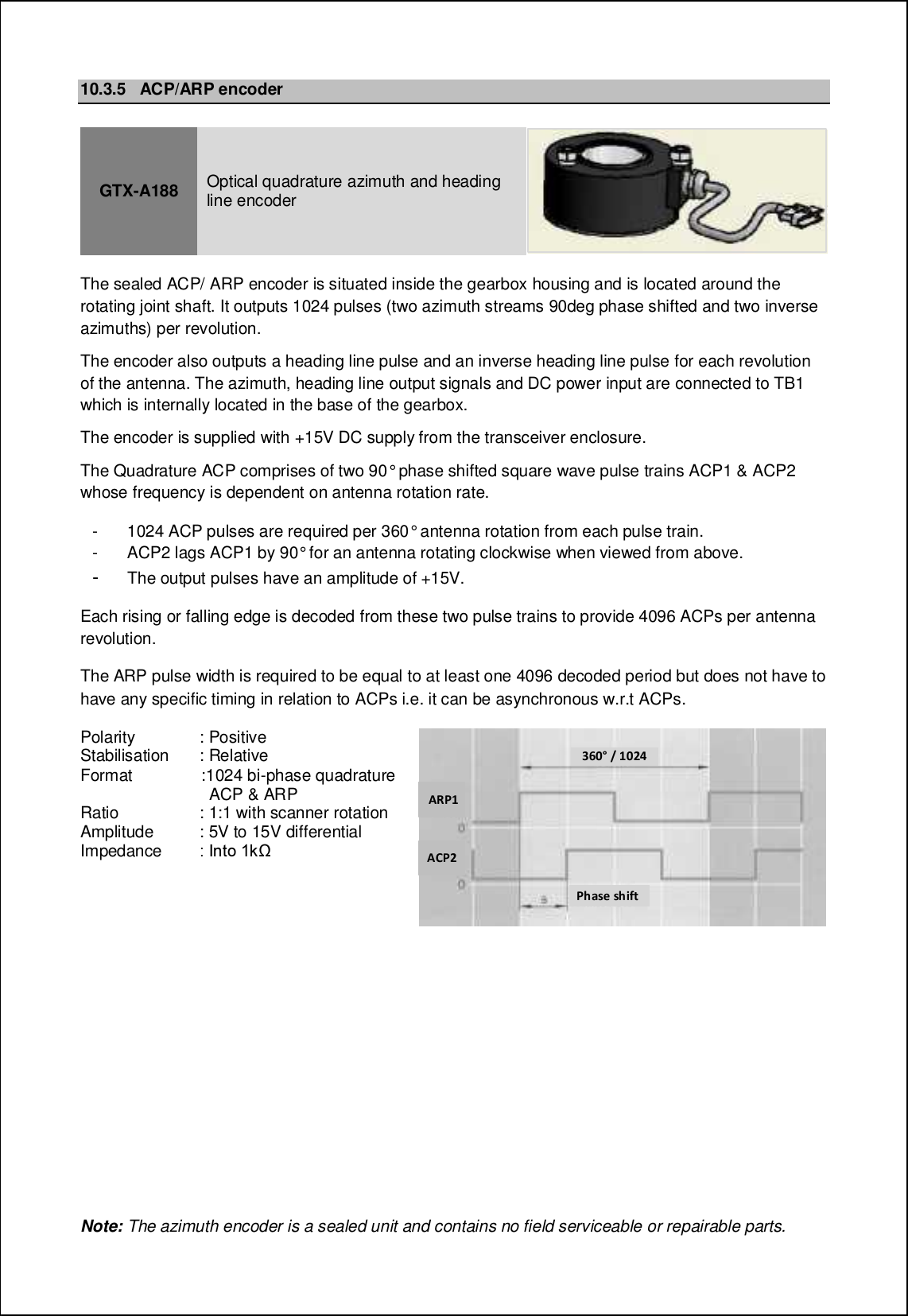
![SBS-900 Shore Based Radar SystemsChapter 1: ContentsKH-1602-2 issue 1: Standard SBS900 Systems Operator & Maintenance HandbookPage 5 of 240SBS-900 Shore Based Radar SystemsThe Kelvin Hughes SBS-900 series is a range of X or S-band SharpEyeTM transceivers designed foruse in shore based radar applications. The SBS-900 range has been designed to enable systemintegrators to provide a radar sensor or range of sensors that meets the following requirements:Equipment StandardsSBS-900 seriesCoastal Surveillance Systems or a Vessel Traffic Services system as definedby IALA recommendations V-128Designed to meet IEC60945 clause 4.5.1 for class B protected equipment forboth emissions and immunityAll Kelvin Hughes designed equipments are designed to meet therequirements of IEC 60950, Safety of information technology equipment.Kelvin Hughes designed equipments are constructed so that access to highvoltages may only be gained after having used a tool, such as a spanner orscrewdriver. Warning labels are prominently displayed both within theequipment and on protective covers.All Kelvin Goab_m Kn^ ^_mcah_^ _kocjg_hn cm ^_mcah_^ [h^ g[ho`[]nol_^ ni J_fpch Goab_m iqh standards of practice being designed to meet the applicable requirements of the following directives:Equipment StandardsCE markingAll KH designed equipments are designed and constructed to KelvinGoab_m iqh mn[h^[l^m i` jl[]nc]_ [h^ [l_ BD g[le_^ qb_l_ l_kocl_^+ meeting the applicable requirements of the following directive:vRTTE Directive 1995/5/ECElectromagneticEmissionsDesigned to meet the requirements of unwanted emissions in the out ofband domain (ITU-R-SM.1541)Designed to meet the requirements of spurious emissions (ITU.R.SM.329.9)© Copyright Kelvin Hughes (2014) limited all rights reserved.No parts of this publication may be reproduced, transmitted, transcribed, translated or stored in anyform or by any means without the written permission of Kelvin Hughes Limited.Technical details contained in this publication are subject to change without notice.When translated, the original English version of the document will remain the definitive document andmbiof^ \_ l_`_ll_^ ni ch [hs mcno[ncih i` ^io\n+ ]ih`omcih il ]ih`fc]n-](https://usermanual.wiki/Kelvin-Hughes/DTX-A3-FDLR/User-Guide-2620132-Page-5.png)
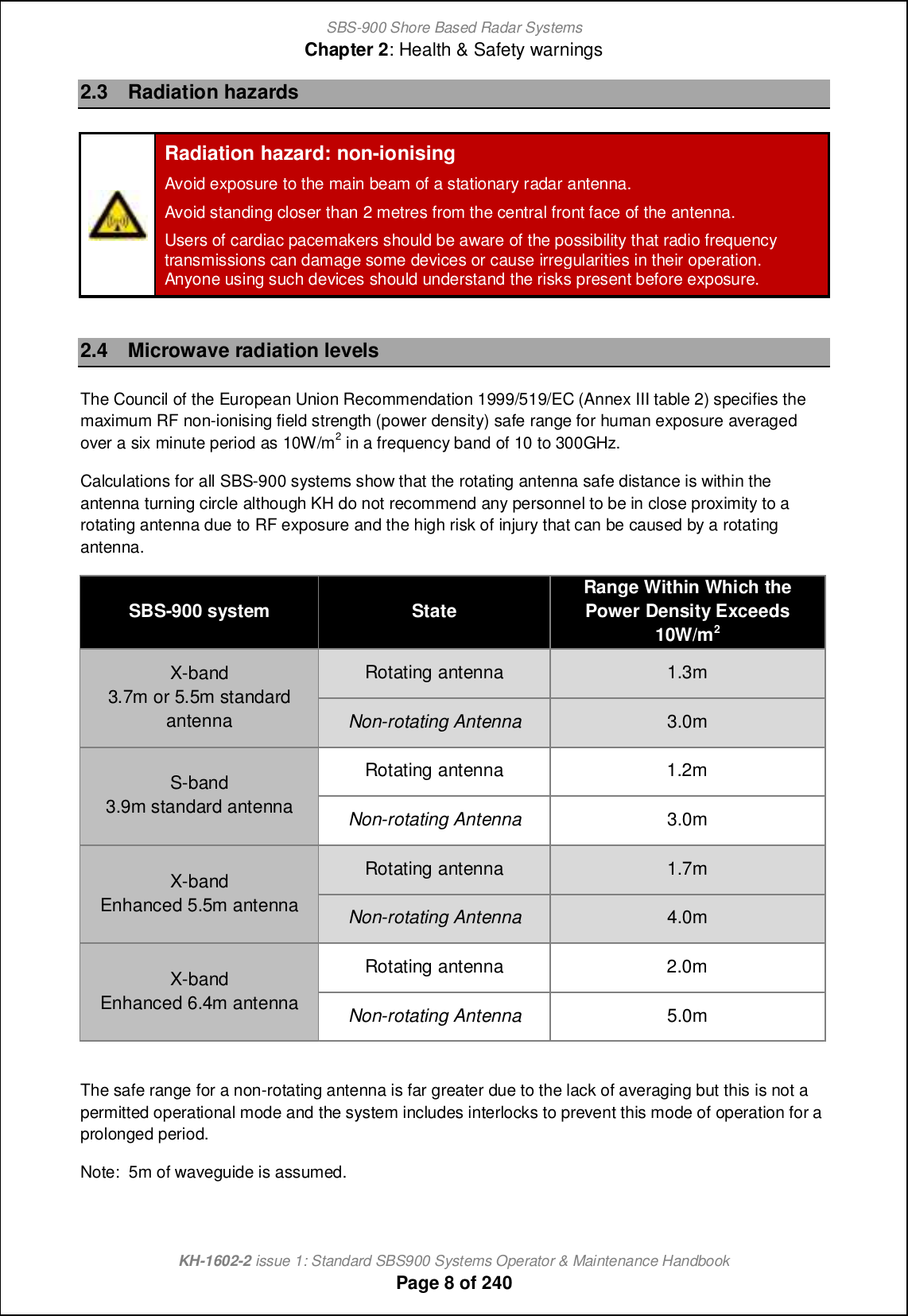
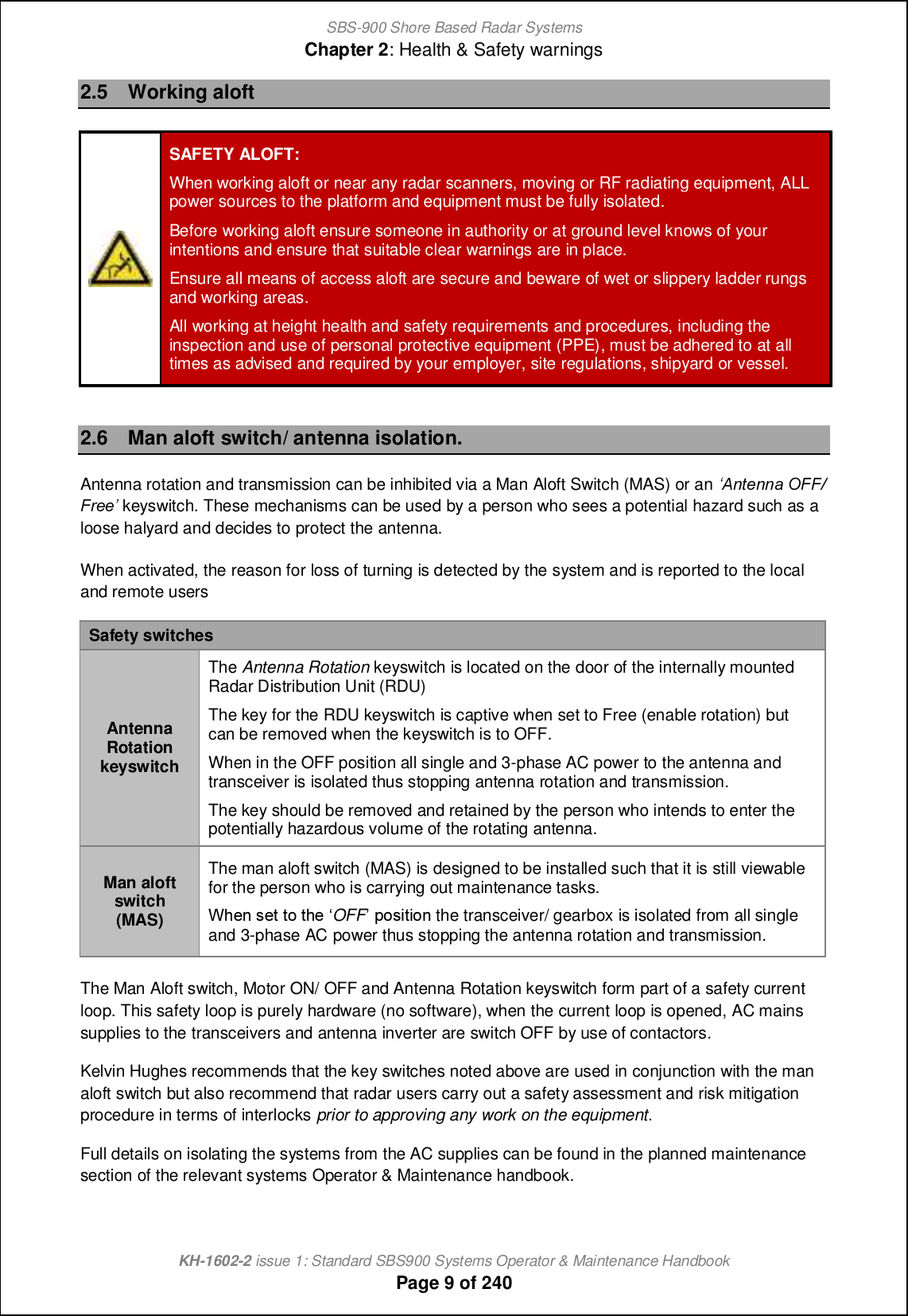
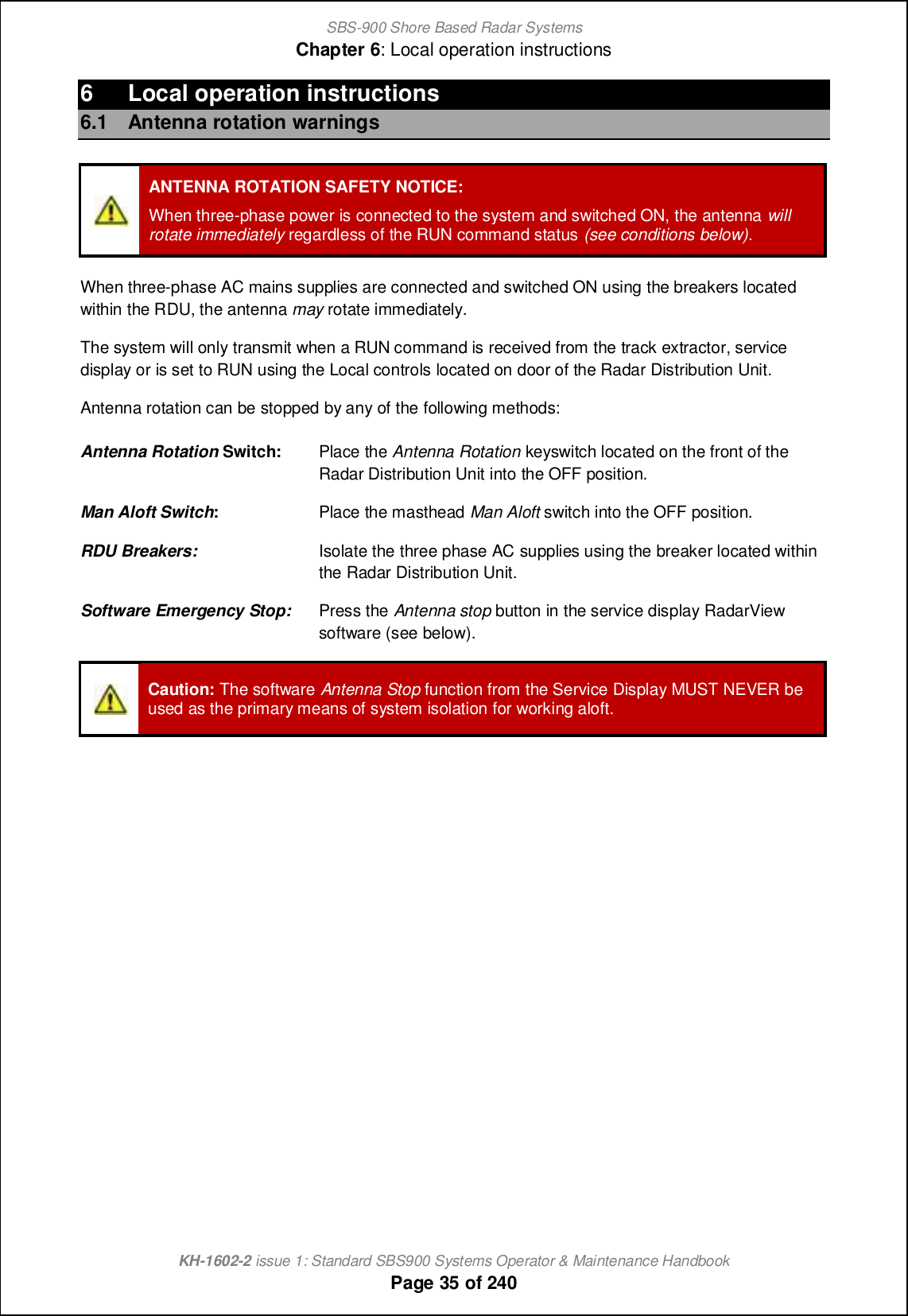
![SBS-900 Shore Based Radar SystemsChapter 2: Health & Safety warningsKH-1602-2 issue 1: Standard SBS900 Systems Operator & Maintenance HandbookPage 7 of 2402 Health & Safety warningsWhen working on Kelvin Hughes equipment, operators, engineers and agents are expected to workwithin the health and safety guidelines noted in the handbook, as issued by their respective employeror as stated by site regulations, shipyard or vessel owner.Risk assessments of a working area must be undertaken prior to commencement of any work andmust be regularly reviewed.2.1 HazardsELECTRICAL HAZARDS:Some equipment does not have safety interlocks fitted.Lethal single and three phase AC and DC voltages may be present when units are openand exposed.Before accessing any internal parts, ALL power sources to the equipment must be fullyisolated; this must include the isolation of all UPS supported supplies to the system.MAINS VOLTAGES:All Kelvin Hughes equipment is supplied with mains input voltage set for 220v, 50/60 Hzac unless otherwise stated on labels attached to the equipment.WARNING: Some equipment contains materials which may produce toxic fumes if burnt.Beryllium warning: The SharpEyeTM X and S band transceivers mounted withinthe SBS-800 series are factory sealed units which contain no field serviceableparts. The SharpEyeTM transceivers must not be dismantled in the field as somecomponents within the factory sealed processor contain Beryllium which ishazardous to health.Class 1 laser product: There is a class 1 laser within the sealed SharpEyetransceiver processor which can represent a risk if the processor isdismantled.When fitted, the LAN fibre optic cable that connects to the SharpEyeTMtransceiver and the to the MISM type 5 modules within the radar distributionunit is considered as a class 1 laser.2.2 Antenna rotation warningANTENNA ROTATION SAFETY NOTICE:When single and three-phase power is connected to the system and switched ON, theantenna will rotate immediately regardless of the RUN command status.Use the antenna rotation keyswitch or man aloft safety switches to stop antenna rotationin an emergency.Q_`_l ni nb_ g[chn_h[h]_ m_]ncih i` nb_ ij_l[nilm b[h^\iie `il ^_n[cfm ih mnijjcha nb_ antenna and isolating a system.](https://usermanual.wiki/Kelvin-Hughes/DTX-A3-FDLR/User-Guide-2620132-Page-7.png)
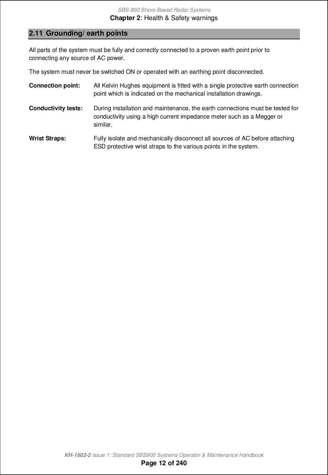
![SBS-900 Shore Based Radar SystemsChapter 2: Health & Safety warningsKH-1602-2 issue 1: Standard SBS900 Systems Operator & Maintenance HandbookPage 10 of 2402.7 Anti-static handlingCAUTION: Handling of electrostatic-sensitive semiconductor devicesCertain semiconductor devices used in the equipment are liable to damage due to staticvoltage. Observe the following precautions when handling these devices in their un-terminated state, or sub-units containing these devices:Persons removing sub-units from equipment containing these devices must be earthedby a wrist strap and a resistor at the labelled point provided on/ within the equipment.'Soldering irons used during authorised repair operations must be low voltage typeswith earthed tips and isolated from the mains voltage by a double insulatedtransformer.'Outer clothing worn must be unable to generate static charges.'Printed circuit boards fitted with these devices must be stored and transported in anti-static containers.'Fit new devices in a special antistatic safe handling area.'Fully isolate and mechanically disconnect all sources of AC before attaching ESDprotective wrist straps to the various points in the system.2.8 RoHS statementRestriction of Hazardous Substances (RoHS): For details on RoHS statements please contactKelvin Hughes; contact details can be found in at the end of this handbook.2.9 End of life disposalWhen the equipment detailed in this handbook has reached the end of its serviceable life, the variousparts that make up the system must be disposed of in accordance with local industrial waste disposalregulations.Please contact your local regulatory body for disposal instructions or contact Kelvin Hughes for a listof any potentially hazardous material contained within the system.SharpEyenspecific disposal noticeSb_ Rb[ljDs_x nl[hm]_cp_l(s) located within the transceiver enclosure are factory sealed units thatcontains no field serviceable parts or lifed components.Components within the Rb[ljDs_x jli]_mmil (all variants) contain traces of beryllium and trivalentchromium.Please contact Kelvin Hughes regarding the repair or a Rb[ljDs_x or its end of life disposalinstructions. Contact details for Kelvin Hughes can be found at the end of this handbook.](https://usermanual.wiki/Kelvin-Hughes/DTX-A3-FDLR/User-Guide-2620132-Page-10.png)

![SBS-900 Shore Based Radar SystemsChapter 3: Software licensing and virus protectionKH-1602-2 issue 1: Standard SBS900 Systems Operator & Maintenance HandbookPage 13 of 2403 Software licensing and virus protection3.1 SoftwareOnly approved software may be used on Kelvin Hughes equipment. The use of unapproved orunlicensed software on any Kelvin Hughes equipment is strictly prohibited. The use of such softwarevoids the warranty status of the unit.Any Kelvin Hughes designed software supplied whether pre-installed, supplied on CD/ DVD or otherremovable media, is the copyright of Kelvin Hughes Ltd, which will not accept any responsibility forany damage or loss caused in whatever way by the use or misuse of the software. This copyrightapplies to software that can be supply in various formats including but not restricted to CD, DVD, USBmemory device, email or obtained via the Kelvin Hughes agents download area.Software supplied with Kelvin Hughes equipment may not be resold or re-distributed without theexpress permission of Kelvin Hughes Ltd.3rd party software supplied with the system such as the RadarView program remains the copyright ofthe original manufacturer. See the manufactures documentation for copyright information.3.2 Virus precautionsMany systems supplied by Kelvin Hughes Ltd including the optional Service Displays are nowPC based and it should be noted that such systems do not have anti-virus protection installed.It is the responsibility of installation engineers, service engineers, maintainers and system usersto ensure that virus threats are not transferred to the system via removable media.WARNING:Prior to use, all removable media used on or in Kelvin Hughes productsMUST be fully scanned for viruses on a PC installed with up to date anti-virus software.Any media containing potential virus infections must not be used.Charges relating to systems found to be infected with a virus will be passed onto thecompany found to be using removable media that has not been suitably scanned.Note: Kelvin Hughes cannot be held responsible for damage caused to systemsby virus infections.Removable media referred to includes but is not restricted to USB memory sticks, USB hard drives,`fijjs ^cm]m+ BC. CUCm [h^ [ff `ilgm i` l_gip[\f_ g_^c[-](https://usermanual.wiki/Kelvin-Hughes/DTX-A3-FDLR/User-Guide-2620132-Page-13.png)


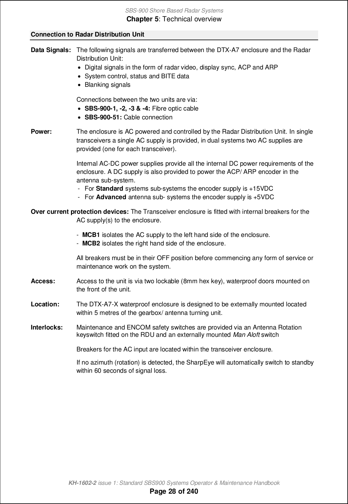
![SBS-900 Shore Based Radar SystemsChapter 5: Technical overviewKH-1602-2 issue 1: Standard SBS900 Systems Operator & Maintenance HandbookPage 29 of 240K[Tec>lXn geTafVX\iXeSharpEyeTM transceiver technology radically departs from conventional marine navigation transceiversthrough the transmission of low power RF pulses and application of pulse compression and Dopplertechniques. The technology benefits from the following:'Solid state transmitter for high reliability 'Dynamic range of 126 dB (including sensitivitytime constant (STC) & pulse compression gain)'Digital pulse compression 'Minimum discernible signal (MDS) of-125dBm'Receiver noise figure <5.5dB 'Internal monitoring, no external componentsrequired to monitor operation'Pulse Doppler processing for improved rainand sea clutter rejection'Range discrimination: 7.5nm (24nm) and15nm (48nm)Solid state technology: Solid state transistors obviate the need for a warm-up time. When theRadar Distribution Unit is switched ON the SharpEyeTM is powered.When a Run command is received by the transceiver, it is ready fortransmission within 40 seconds.Output power: When transmitting, the amplifiers generate a nominal peak power of170Watts with a maximum duty cycle of 13% at the transceiveroutput flange.System monitoring: Comprehensive built in test (BIT) facilities within the transceiverprovide on-line monitoring of the following parameters within thetransceiver:'RF power 'Antenna systemVSWR'Power supplies'Temperature 'Receiversensitivity'Antenna rotationdataShould the system detect a fault condition which could lead to earlyfailure of the transceiver, i.e. a high VSWR, then the transceiverswitches to a low power state which permits transmission to continuein the short term. The built in test monitoring also ionjonm [ •Kiq QEOiq_l q[lhcha g_mm[a_ c` nb_ QE jiq_l ionjon `[ffm \_fiq 0// V- Sb_ ^_mcah cm •`[cf-mi`n nb_l_\s jlipc^cha al[]_`of ^_al[^[ncih ch nb_ event of single or multiple transistor failures.SBS-900 Range: System ID SharpEyeTMTransceiver Doppler FrequencyDiversitySBS-900-1 X-band & %SBS-900-2 X-band & &SBS-900-3 X-band(dual redundant) & &SBS-900-4 X and S-band(dual transceiver) &(X & S-band)&(X-band only)SBS-900-51 S-band & %](https://usermanual.wiki/Kelvin-Hughes/DTX-A3-FDLR/User-Guide-2620132-Page-29.png)
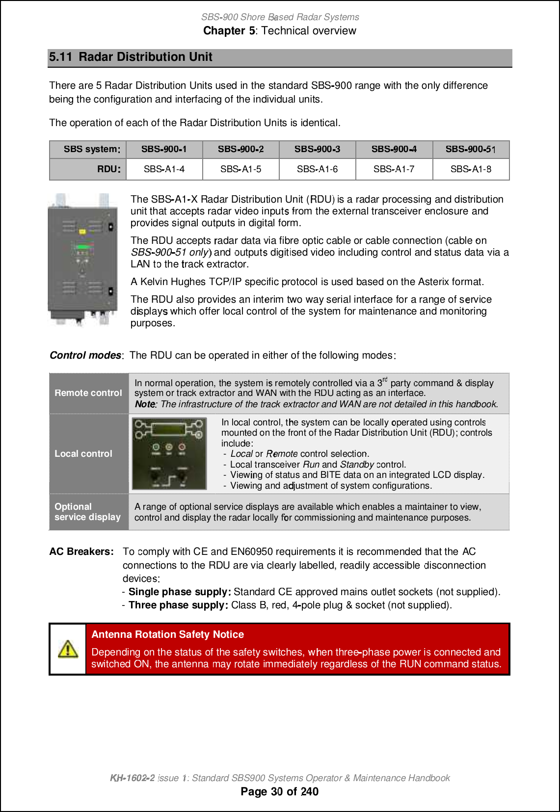


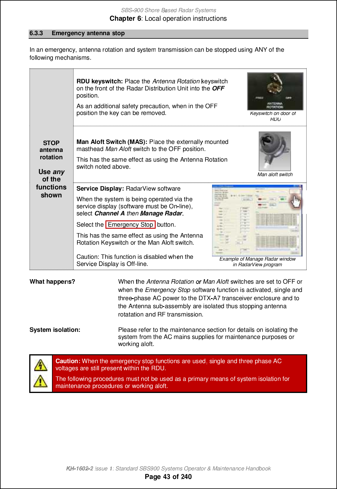
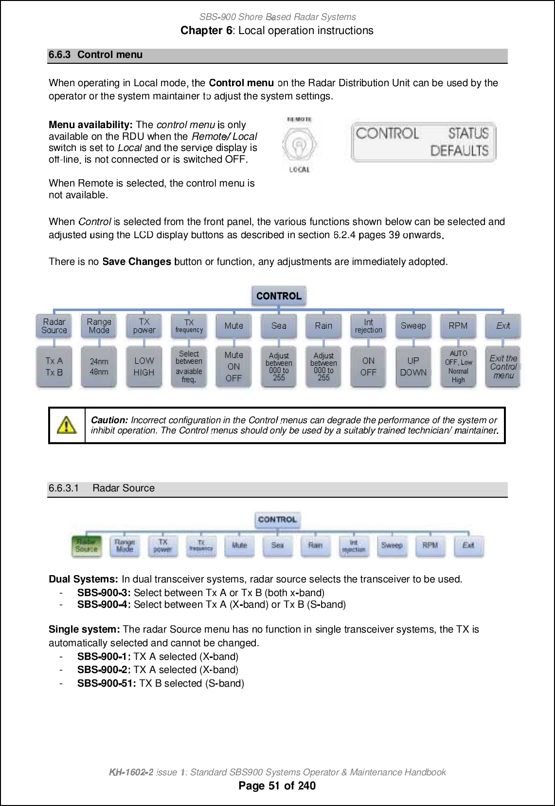
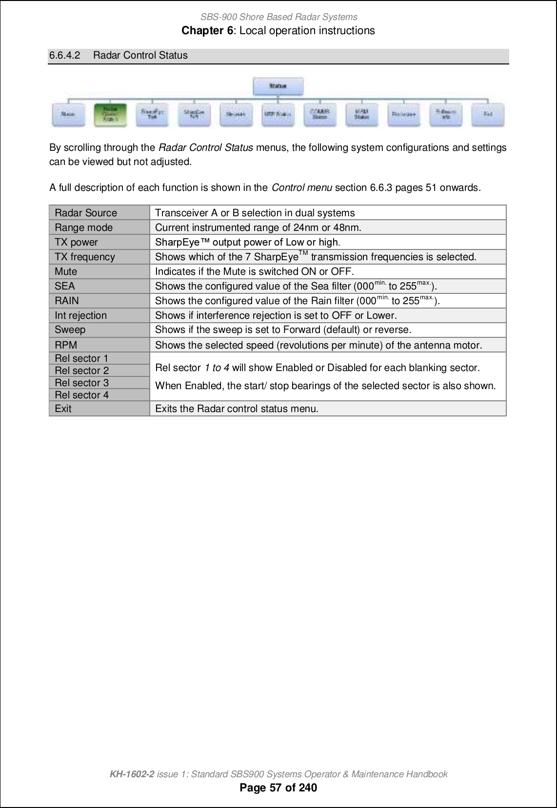
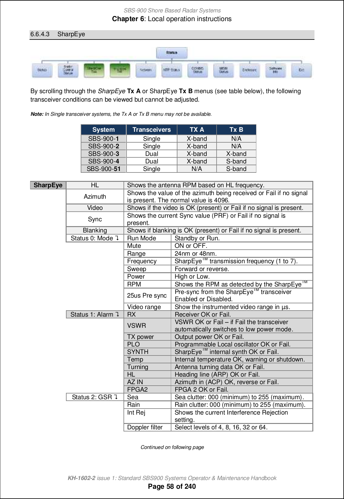
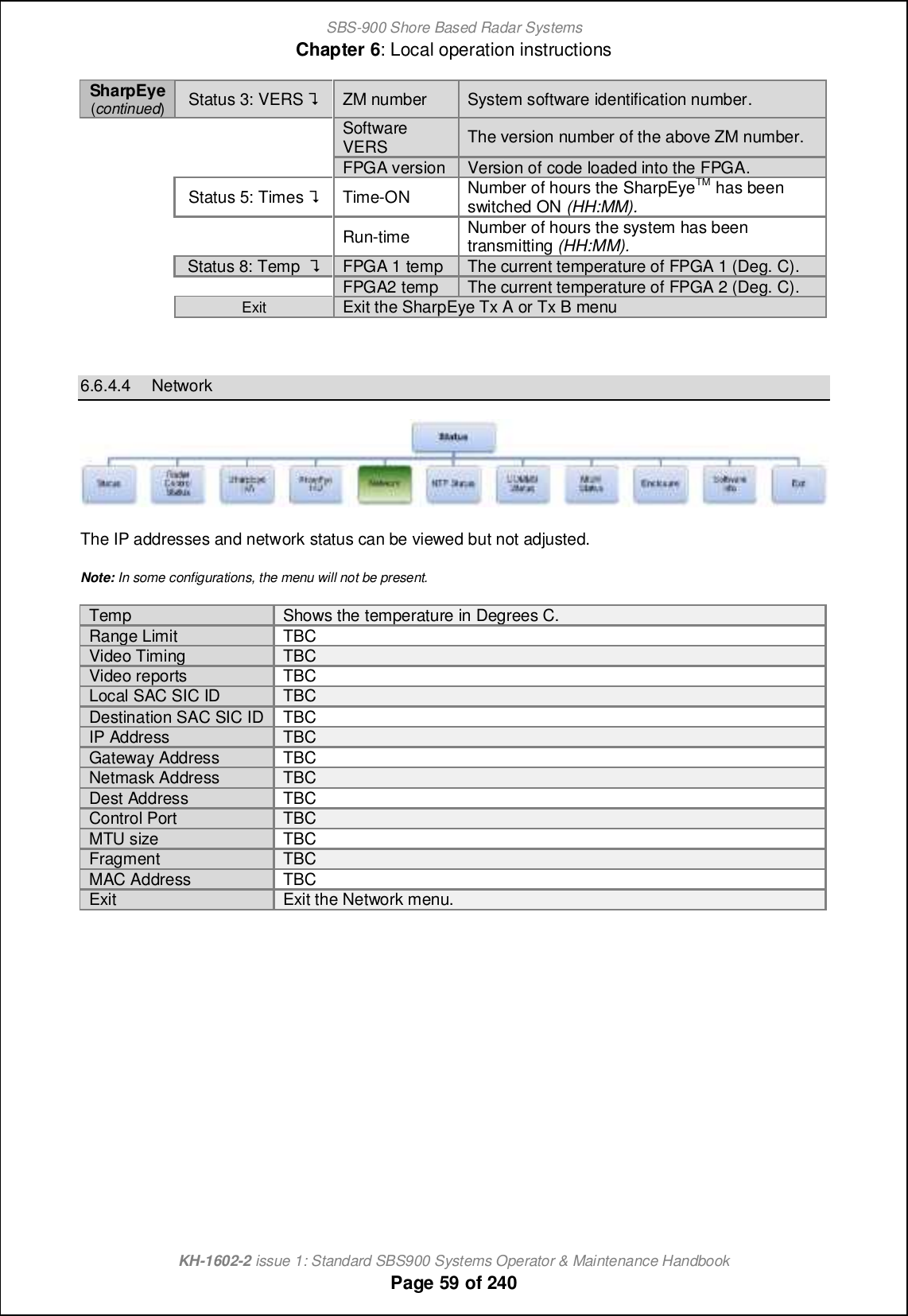
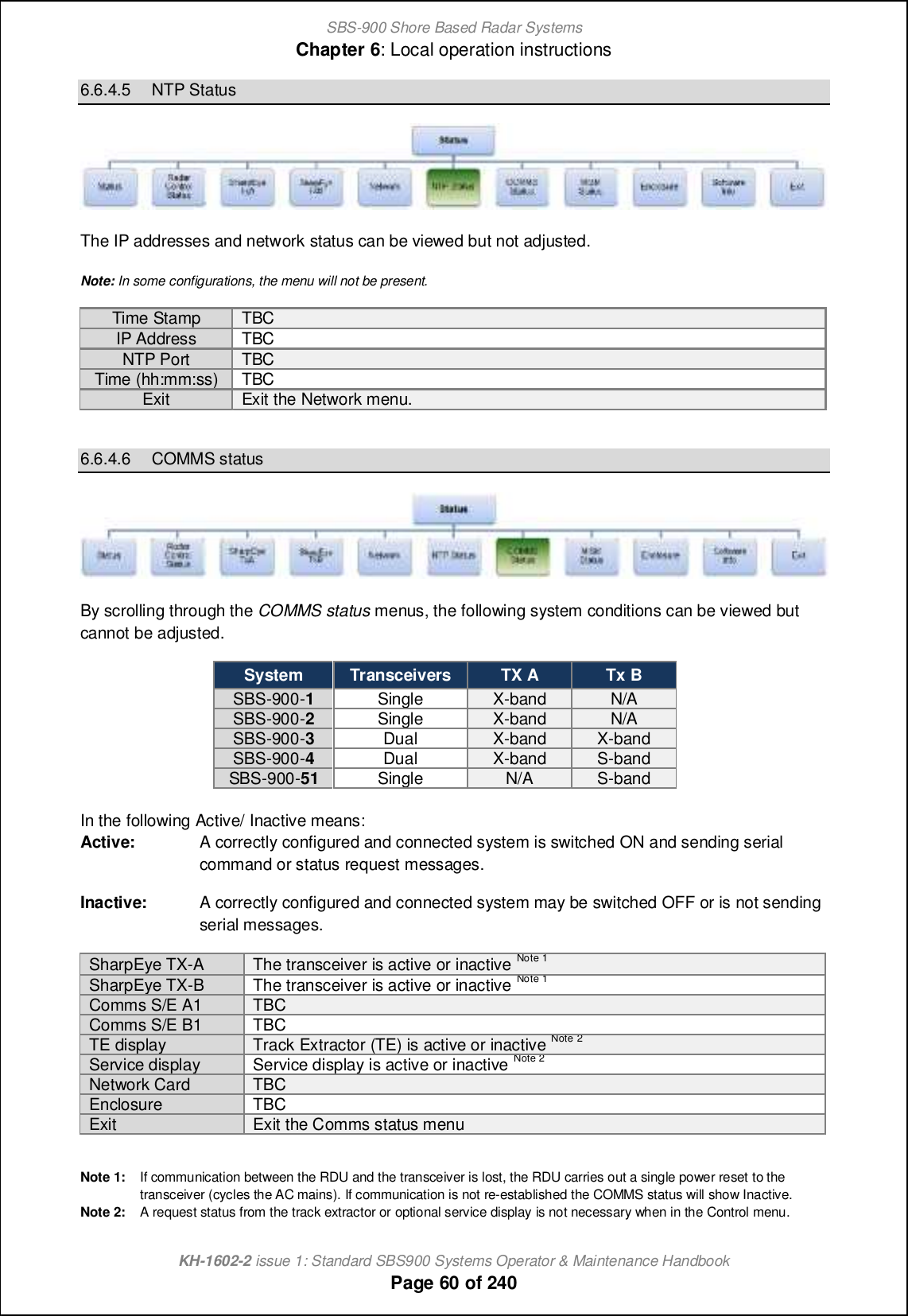
![SBS-900 Shore Based Radar SystemsChapter 6: Local operation instructionsKH-1602-2 issue 1: Standard SBS900 Systems Operator & Maintenance HandbookPage 44 of 2406.4 Local control operational statesFor the purposes of the following explanations, track extractor g_[hm nb_ om_lm ]igg[h^ [h^ display system or track extractor.SystemOFFSystemconfiguration'Single and three-phase AC supplies to the RDU are available.'Breakers within RDU are OFF.'Antenna Rotation keyswitch & Man aloft switch both set to OFF.'Remote/ Local &standby/ RUN switches on the RDU set to Remote &standby.'No commands being received from the Service Display.System status'AC power is present within the RDU but as the breakers are in the OFFposition, the dual redundant power supply is OFF and no DC rails arebeing generated.The Radar Distribution Unit is OFF.'Single and three-phase mains voltages are NOT sent to the transceiver /gearbox.SystemRUNSafetyswitchesOFFSystemconfiguration'Single and three-phase AC supplies to the RDU are switched ON.'The AC Breakers within RDU are ON.'Antenna Rotation keyswitch OR Man Aloft switch set to OFF.'Remote/ Local &standby/ RUN switches on the RDU set to Local &Standby.System status'The RDU detects that the Antenna Rotation keyswitch OR Man Aloftswitches are in the OFF position. This breaks the safety switch current loop.'The single and three-phase relays are opened and AC power to thetransceiver/ gearbox is switched OFF.'Antenna rotation and transmission is not possible'The Service Display has no control over the system.SystemstandbySystemconfiguration'Single and three-phase AC supplies to the RDU are available.'The AC Breakers within RDU are ON.'Antenna Rotation keyswitch & Man Aloft switch both set to FREE.'Remote/ Local &standby/ RUN switches on the RDU set to Local &Standby.System status'The RDU is switched ON. The software reads the condition of the AntennaRotation keyswitch and Man Aloft switch, detects these are in the FREEposition so makes relays within the breakers sending AC power to thetransceiver/ gearbox.'The antenna commences rotation regardless of the RUN commandState. Note'The SharpEye transceiver switches ON and after a 30 to 40 second warm-up time enters a standby state waiting for a RUN command from the RDU.'System and BITE data from both the RDU and transceiver is available.'The system is now in standby waiting commands from the Service Display.SystemRUNSystemconfiguration'Single and three-phase AC supplies to the RDU are switched ON.'The AC Breakers within RDU are ON.'Antenna Rotation keyswitch & Man Aloft switch both set to FREE.'Remote/ Local &standby/ RUN switches on the RDU set to Local & RUN.System status'The RDU detects that the RDU switches are set to Local and RUN.'The RUN command is sent to the transceiver which commencestransmitting.'Radar signals, ACP, ARP and heading line data is sent to the radar I/Omodule within the RDU.Note: Antenna rotation can be over-ridden in the Control Defaults menu.](https://usermanual.wiki/Kelvin-Hughes/DTX-A3-FDLR/User-Guide-2620132-Page-44.png)

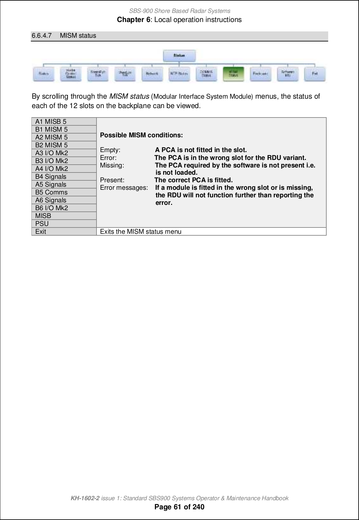
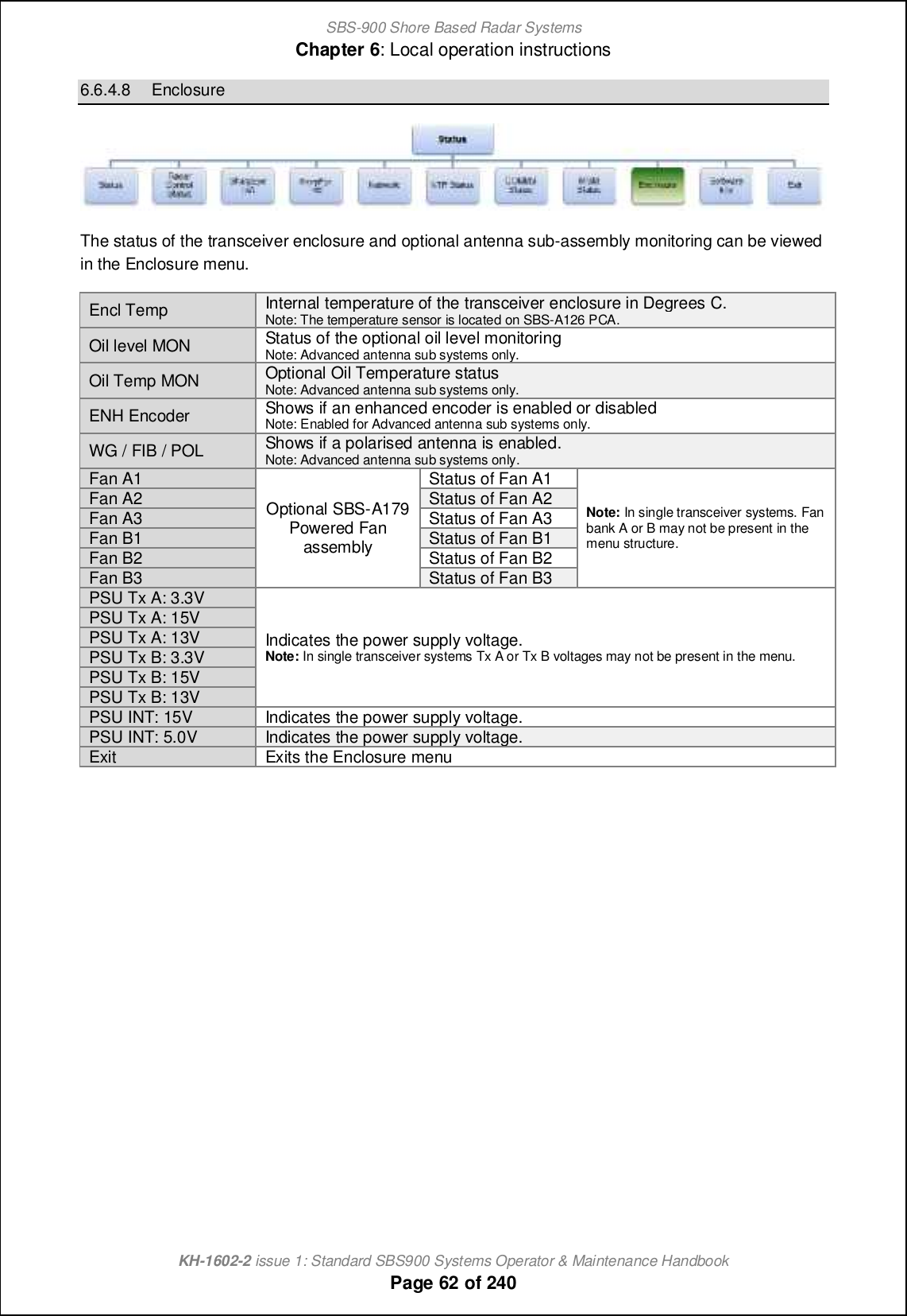
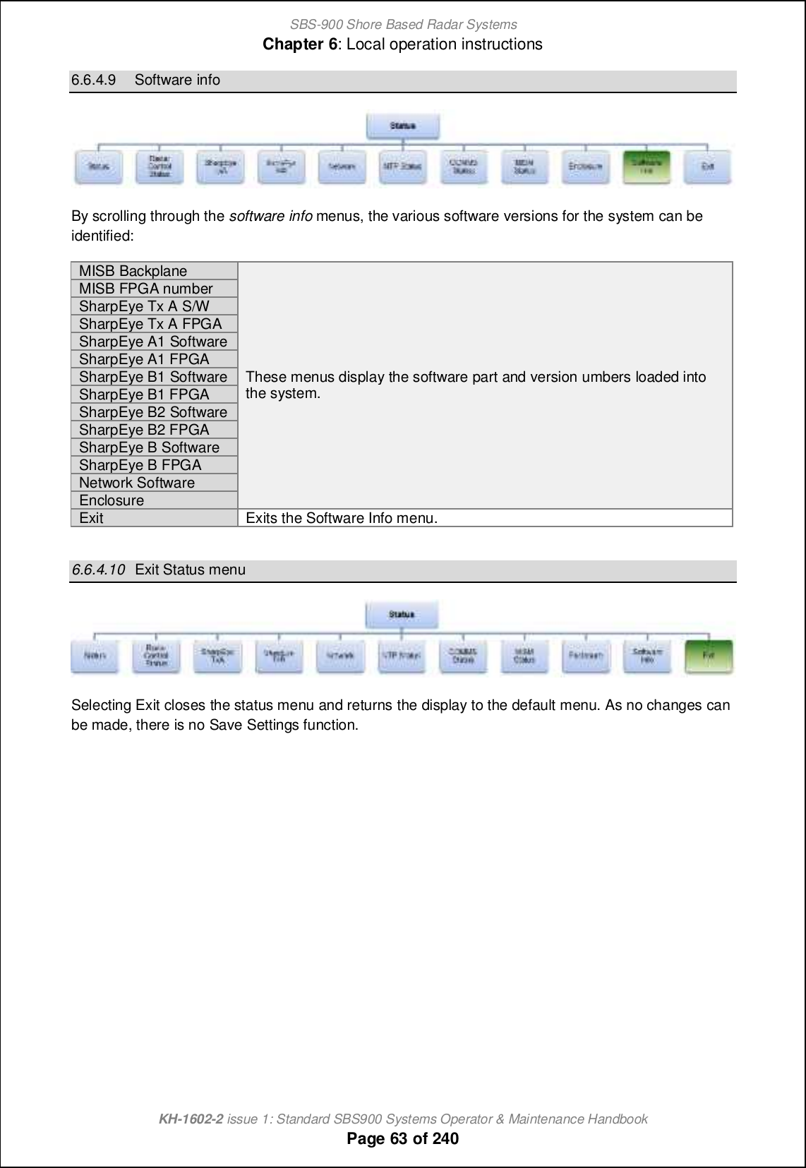
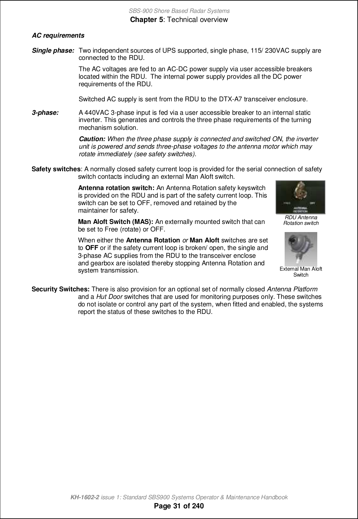
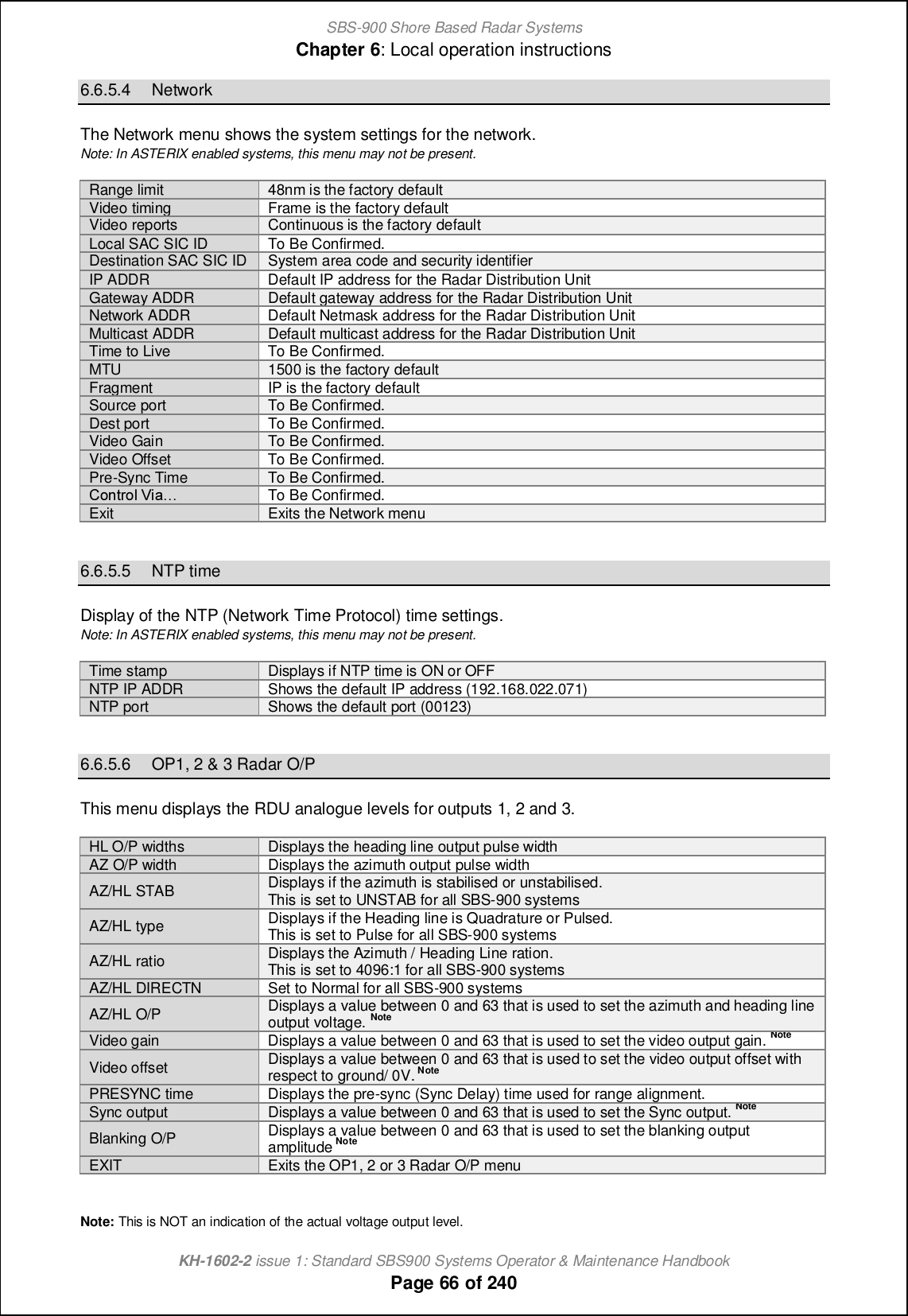
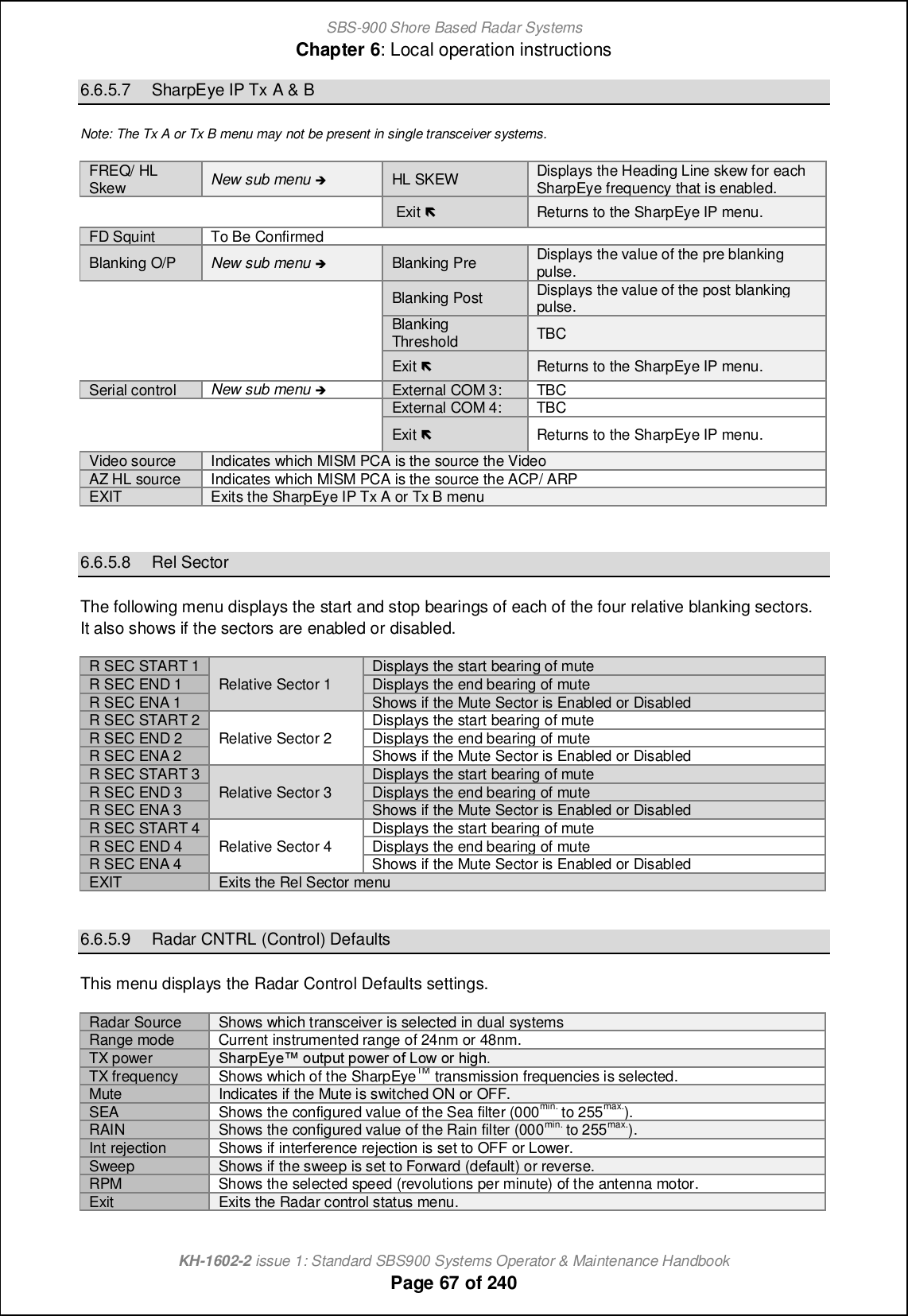
![SBS-900 Shore Based Radar SystemsChapter 6: Local operation instructionsKH-1602-2 issue 1: Standard SBS900 Systems Operator & Maintenance HandbookPage 65 of 2406.6.5.1 BrightnessBrightness is used to set the backlight brilliance of the LCD front panel on the Radar Distribution Unit.Bright+Increases the backlight brilliance of the front panel.Bright -Decreases the backlight brilliance of the front panel.6.6.5.2 Variant OptionsThe Variant Options menu shows the system configuration.SBS variant Shows the SBS system numberi.e.SBS-900-1.CAN Mode Shows the CAN mode as OFF, RIU, TIU or Fixed.CAN AddressTo Be Confirmed.TX PSU CONT Set to Always ON in SBS-900 systems.Days to Swap Shows the number of days until the transceiver automatically swaps (Dual transceiversystems only).Door switch Enabled where a Hut door security switch is connected.WG dryerEnabled when the optionalpressurized waveguide dryer isinstalled.Platform switch Enabled where an Antenna Platform security switch is fitted.Horizontal POLEnabled when a polarised antenna is being fitted.Circular POLAnti-clock POLVertical POLENH Encoder Fitted is displayed when an enhanced encoder is installed.Oil status Enabled when the optional oil monitoring input from the Advanced antenna Turning Unit isinstalled.Fan Bank A Enable or disable the optional powered fan kit for Tx A.Note: In single Transceiver systems, this menu may not be present.Fan Bank B Enable or disable the optional powered fan kit for Tx B.Note: Insingle Transceiver systems, this menu may not be present.Active Fan Set the temperature that Fan Bank A switches on or set to permanently ON.Note: In single Transceiver systems, this menu may not be present.Reserve Fan Set the temperature that Fan Bank B switches on or set to permanently ON.Note: In single Transceiver systems, this menu may not be present.Minimum FREQ Displays nb_ gchcgog [p[cf[\f_ Rb[ljDs_x `l_ko_h]s.Maximum FREQDisplaysnb_ g[rcgog [p[cf[\f_ Rb[ljDs_x `l_ko_h]s.Low RPM Enabled when LOW RPM antenna speeds have been commissioned.High RPMEnabled when HIGH RPM antenna speeds have been commissioned.Auto RPM Enabled when AUTO RPM antenna speeds have been commissioned.Alt Chan Plan This allows the system toNote: Systemspecific menu, this may not be present in standard system.Ant Gain Allows the selection of the antenna gain when Alt Chan Plan is selected.Note: System specific menu, this may not be present in standard system.EXITExits the Variant Options Menu.6.6.5.3 Serial PortsThe serial ports menu displays the baud rates configured for the serial outputs to the transceiver,Service Display (SKL: Service display serial port) or the optional analogue track extractor (SKK: TEserial port).TE port Displays the Baud Rate for the Track Extractor (TE) outputService portDisplays the Baud Rate for the Service Display.TX/ RX A Ccmjf[sm nb_ A[o^ Q[n_ `il nb_ Rb[ljDs_x SW . Qr @-TX/ TX BCcmjf[sm nb_ A[o^ Q[n_ `il nb_ Rb[ljDs_x SW . Qr A-EXITExits the Serial Ports menu](https://usermanual.wiki/Kelvin-Hughes/DTX-A3-FDLR/User-Guide-2620132-Page-65.png)

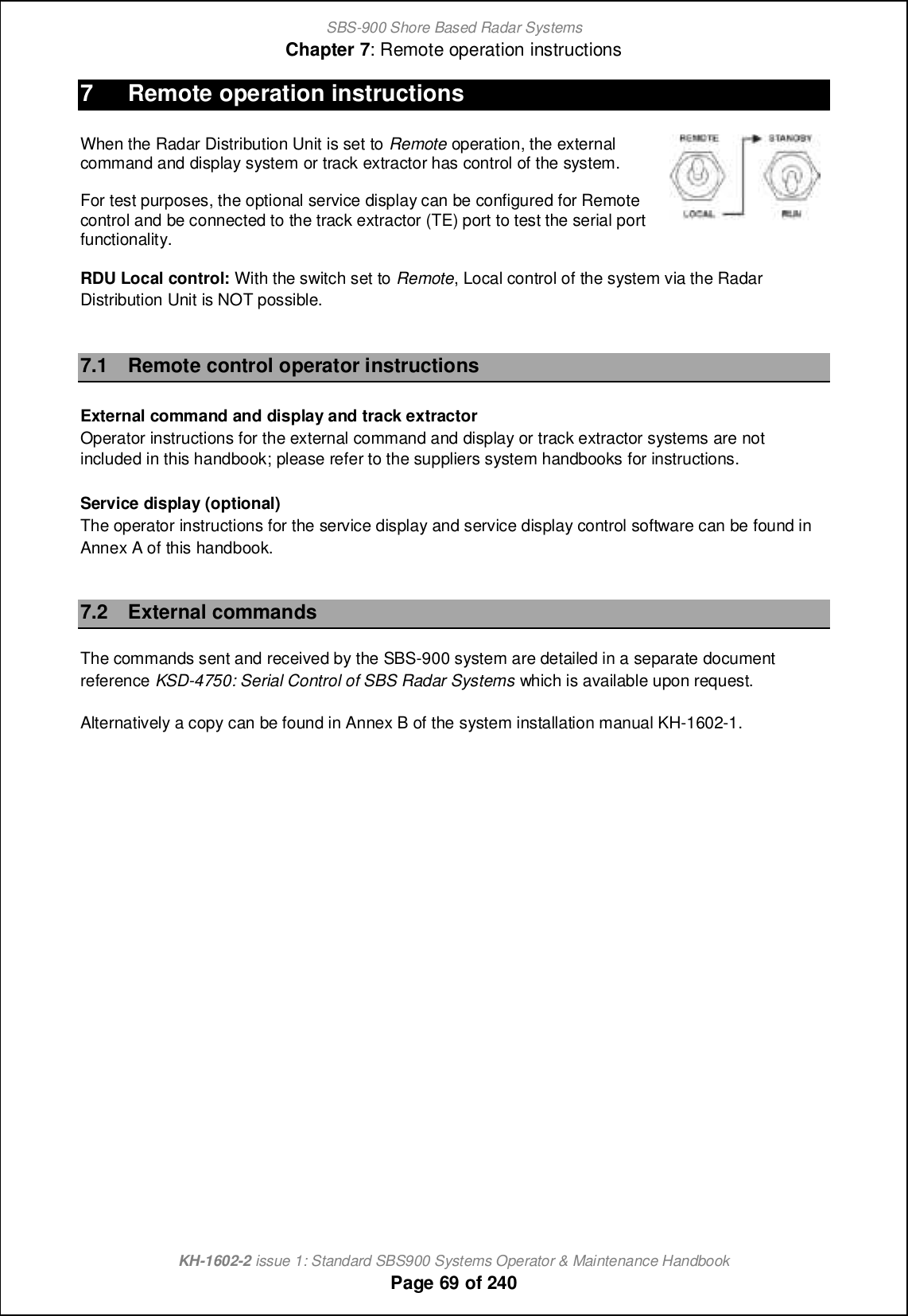
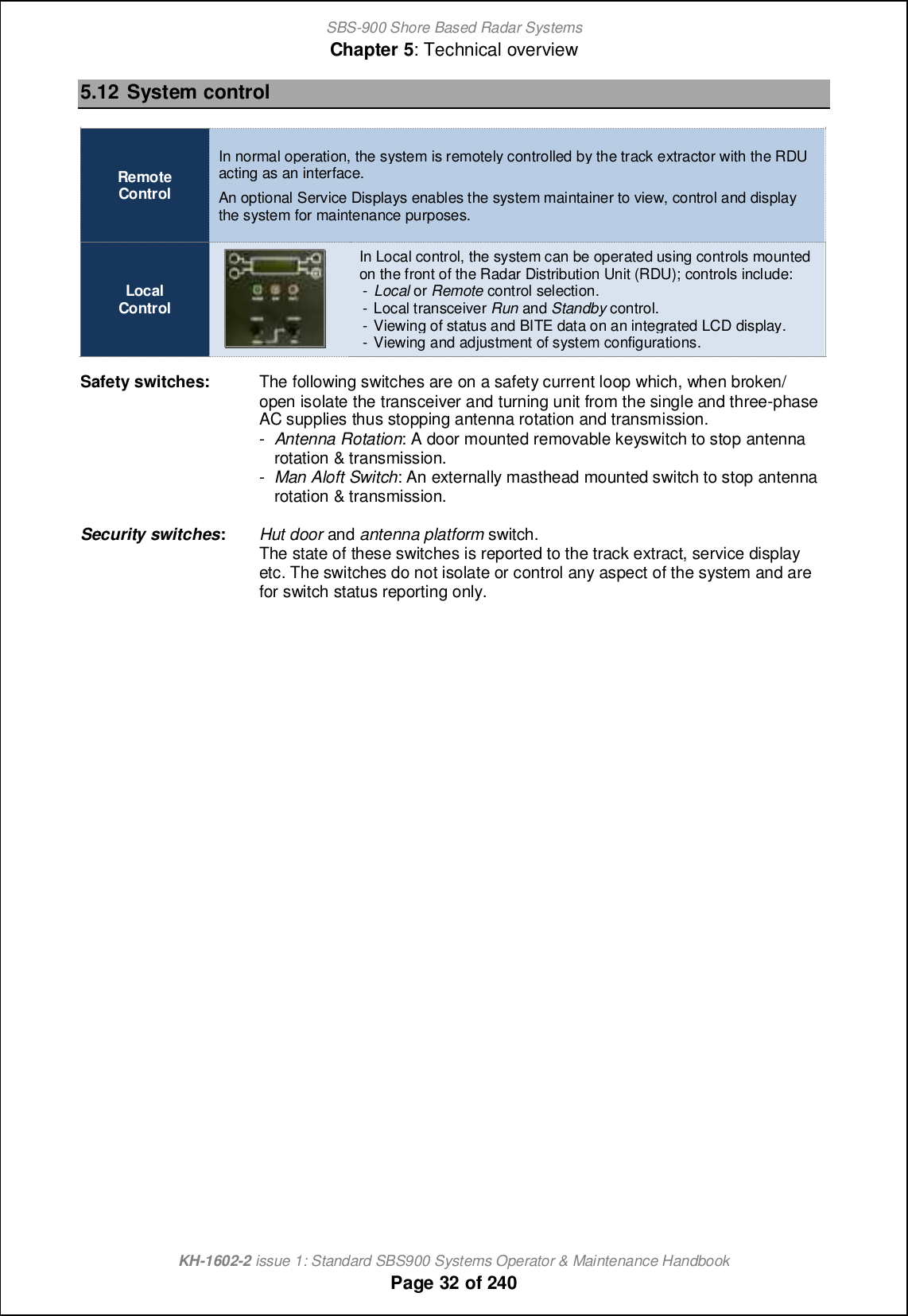
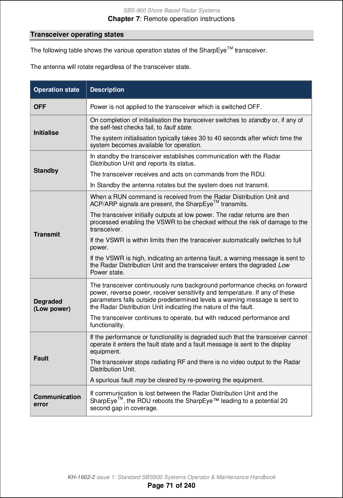
![SBS-900 Shore Based Radar SystemsChapter 7: Remote operation instructionsKH-1602-2 issue 1: Standard SBS900 Systems Operator & Maintenance HandbookPage 70 of 2407.3 Remote control operational statesEil nb_ joljim_m i` nb_ `iffiqcha _rjf[h[ncihm+ nl[]e _rnl[]nil g_[hm nb_ om_lm ]igg[h^ [h^ display system or track extractor.SystemOFFSystemconfiguration'Single and three-phase AC supplies to the RDU are available.'The AC Breakers within RDU are OFF.'Antenna Rotation keyswitch & Man aloft switch both set to OFF.'Remote/ Local &Standby/ RUN switches on the RDU are set to Remote &Standby.'Commands being received from the Service Display.System status'AC power is present within the RDU but as the breakers are in the OFFposition, the dual redundant power supply is OFF and no DC rails arebeing generated.The Radar Distribution Unit is OFF.'Single and three-phase mains voltages are NOT sent to the transceiver /gearbox.SystemRUNSafetyswitchesOFFSystemconfiguration'Single and three-phase AC supplies to the RDU are switched ON.'The AC Breakers within RDU are ON.'Antenna Rotation keyswitch OR Man Aloft switch set to OFF.'Remote/ Local &Standby/ RUN switches on the RDU are set to Remote &Standby.System status'The RDU detects that the Antenna Rotation keyswitch OR Man Aloftswitches are in the OFF position. This breaks the safety switch current loop.'The single and three-phase relays are opened and AC power to thetransceiver/ gearbox is switched OFF.'Antenna rotation and transmission is not possible.'The Service Display has no control over the system.SystemStandbySystemconfiguration'Single and three-phase AC supplies to the RDU are available.'The AC Breakers within RDU are ON.'Antenna Rotation keyswitch & Man Aloft switch are both set to FREE.'Remote/ Local &Standby/ RUN switches on the RDU are set to Remote &Standby.'No commands being received from the Service Display.System status'The RDU is switched ON. The software reads the condition of the AntennaRotation keyswitch and Man Aloft switch, detects these are in the FREEposition so makes relays within the breakers sending AC power to thetransceiver and gearbox.'The antenna commences rotation regardless of the RUN commandState. Note'The SharpEye transceiver switches ON and after a 30 to 40 second warm-up time enters a standby state waiting for a RUN command from the RDU.'System and BITE data from both the RDU and transceiver is available.'The system is now in standby waiting for system commands.RemotecontrolSystemRUNSystemconfiguration'Single and three-phase AC supplies to the RDU are available.'The AC Breakers within RDU are ON.'Antenna Rotation keyswitch & Man Aloft switch both set to FREE.'Remote/ Local &Standby/ RUN switches on the RDU set to Remote &Standby.'ARUN commandis being received.System status'The RDU detects the RUN command which is sent to the transceiver.'The SharpEye is in a standby state with the antenna running. When the runcommand is received from the RDU the system commences transmitting.'Radar signals, ACP, ARP and heading line data is sent to the radar I/Omodule within the Radar Distribution Unit.'The RDU processes the transceiver data and sends it to the track extractorand optional service display.Note: Antenna rotation can be over-ridden in the Control Defaults menu.](https://usermanual.wiki/Kelvin-Hughes/DTX-A3-FDLR/User-Guide-2620132-Page-70.png)

![SBS-900 Shore Based Radar SystemsChapter 8: Service display/ RadarView controlKH-1602-2 issue 1: Standard SBS900 Systems Operator & Maintenance HandbookPage 73 of 2408 Service display/ RadarView control8.1 OverviewSBS systems can be controlled and radar returns viewed using the optional range of service displays.Service displays can be used as a maintenance/ commissioning tool or when correctly configured, asa primary means of system control.There are a number of service display options for the SBS series as follows:Service display part number & description SBS-900-1SBS-900-2SBS-900-51SBS-900-3SBS-900-4SBS-A3-2 Single radar sensorBase components for integration into a 3rd party supplied PC & &SBS-A3-3 Single radar sensor displayRS232/ ASTERIX control & monitoring & &SBS-A3-5 Single radar sensorLAN/ ASTERIX and RS232 control & monitoring(No radar input card fitted)%&LAN kit required.See NoteAll service displays are supplied with the following software pre-loaded.ZM-2283RadarView softwareRadarView Software: This software provides the radar processing and displayand has integrated control and monitoring functions for the SBS series.Operator instructions: The use and operator instructions for the ZM-2283RadarView and SBS control software can be found in Annex B.8.2 SBS-A3-2 Base systemThe SBS-A3-2 allows the serial control of a single transceiver system via a customer supplied thirdparty PC/ Microprocessor. See the options section in the system overview handbook for the minimumPC specification.The kit provides all the hardware and software to be installed onto a PC to make the systemcompatible with the SBS series and comprises the following:Kelvin Hughespart number DescriptionSBS-A109 08 l[]e giohn[\f_ '0T( mervice display patch panel and cablesZM-2283 RadarView software including SBS radar control and replay software formaintenance displays.Supports of HPx-200 and/ or Asterix video.45-980-0041-001 HPx-200 PCI radar interface cardZM-2602 SBS service display graphic V2Note: The SBS-A3-5 service display can only be used with the LAN kit is fitted.](https://usermanual.wiki/Kelvin-Hughes/DTX-A3-FDLR/User-Guide-2620132-Page-73.png)
![SBS-900 Shore Based Radar SystemsChapter 8: Service display/ RadarView controlKH-1602-2 issue 1: Standard SBS900 Systems Operator & Maintenance HandbookPage 74 of 2408.3 SBS-A3-3 Single transceiverThe SBS-A3-2 ecn ]ihn[chm [ 08 l[]e giohn[\f_ '1T( gc]lijli]_mmil jl_fi[^_^ qcnb [ff nb_ necessary software and an interface place for connecting the system to a single transceiver system.Kelvin Hughes partnumberDescription45-975-0183-001 08 '2U) rack mountable microprocessor.SBS-A109 08 l[]e giohn[\f_ '0T( mervice display patch panel and cablesZM-2283 RadarView software including SBS radar control and replay software formaintenance displays.Supports of HPx-200 and/ or Asterix video.45-980-0041-001 HPx-200 PCI radar interface card (preinstalled into the PC)ZM-2602 SBS service display graphics card (preinstalled into the PC)SBS-A124-11 Cable kit for connecting the SBS-A109 plate to the SBS system (11m)Note: Other cable lengths are available; please contact Kelvin Hughes for additional details.8.4 SBS-A3-4 dual transceiverThe SBS-A3-3 ecn ]ihn[chm [ 08 l[]e giohn[\f_ '1T( gc]lijli]_mmil jl_fi[^_^ qcnb [ff nb_ necessary software and two interface places for connecting to a dual transceiver system.Kelvin Hughes partnumberDescription45-975-0183-001 08 '2U) rack mountable microprocessor.SBS-A109 1 r 08 l[]e mountable (1U) service display patch panel and cablesZM-2283 RadarView software including SBS radar control and replay software formaintenance displays.Supports of HPx-200 and/ or Asterix video.45-980-0041-001 2 x HPx-200 PCI radar interface card (preinstalled into the PC)ZM-2602 SBS service display graphics card (preinstalled into the PC)SBS-A124-11 Cable kit for connecting the SBS-A109 plate to the SBS system (11m)Note:Othercablelengths are available; please contact Kelvin Hughes foradditional details.SBS-A3-3Service displaySingle transceiverSBS system Video/ Sync (analogue)Serial controlSBS-A3-3Service displayDual transceiverSBS system 2 x Video/ Sync (analogue)2 x Serial control](https://usermanual.wiki/Kelvin-Hughes/DTX-A3-FDLR/User-Guide-2620132-Page-74.png)
![SBS-900 Shore Based Radar SystemsChapter 8: Service display/ RadarView controlKH-1602-2 issue 1: Standard SBS900 Systems Operator & Maintenance HandbookPage 75 of 2408.5 SBS-A3-5 ASTERIX controlThe SBS-A3-4 ecn ]ihn[chm [ 08 l[]e giohn[\f_ '1T( gc]lijli]_mmil jl_fi[^_^ qcnb [ff nb_ necessary software for connection to a dual transceiver system.The service display can accept ASTERIX video and control is possible via Serial or LAN connection.NoteKit contentsThe SBS-A3-4 dual radar service kit comprises of the following:45-975-0183-001 08 '2U) rack mountable microprocessor.ZM-2283 RadarView software including SBS radar control and replay software formaintenance displays.Supports of HPx-200 and/ or Asterix video.ZM-2602 SBS service display graphics card (preinstalled into the PC)SBS-A220-11 Cable kit for connecting the SBS-A109 plate to the SBS system (11m)Note28.6 Keyboard, monitor & MouseThe processor requires a flat screen display, standard USB QWERTY keyboard and USB mouse (notsupplied). If these are required the following commercial off the shelf products can be supplied:Kelvin Hughes partnumber DescriptionMonitor45-975-0189-00122 inch wide screen LCD monitor.Auto-ranging AC input 110VAC to 230VAC 47Hz to 63Hz.Case colour black.Keyboard45-975-0191-001 USB QWERTY keyboard, case/ key colour black.Mouse45-975-0190-001 Black USB optical scroll mouse with three buttons.Note 1: LAN control is only available when the LAN interface kit has been fitted to the Radar Distribution Unit (kit referenceSBS-A129).Note 2: Other cable lengths are available; please contact Kelvin Hughes for additional details.SBS-A3-3Service displayDual transceiverSBS system 2 x Serial controlOr LAN controlNote 1](https://usermanual.wiki/Kelvin-Hughes/DTX-A3-FDLR/User-Guide-2620132-Page-75.png)
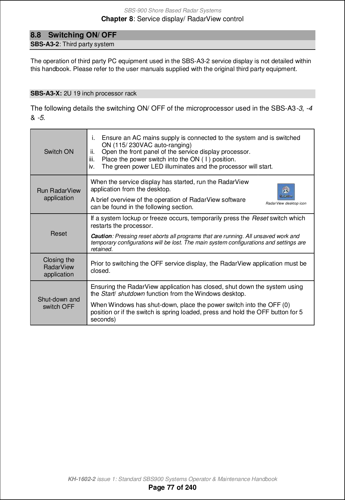
![SBS-900 Shore Based Radar SystemsChapter 8: Service display/ RadarView controlKH-1602-2 issue 1: Standard SBS900 Systems Operator & Maintenance HandbookPage 76 of 2408.7 Service Display PC overviewSb_ `iffiqcha acp_m [h ip_lpc_q i` nb_ 08 '1T( l[]e giohn_^ gc]lijli]_mmil om_^ ch nb_ SBS-A3-3,-4 &-5 service displays.Note: The make and model of the service display PC may change from the version shown however the switch functionalityand input/ output connectivity will be similar.SBS-A3-3 Service display front viewDetail of service display controlsSBS-9.-67 .6q eTV^ `bhagTU_X %.M& fXei\VX W\fc_Tl \agXeYTVX c_TgX7The following plate is used to connect signals to the service display (1 plate required per transceiver).The system runs the software required to display and control a single radar sensor but does notinclude a monitor, keyboard or mouse.Air filterReset switchPower switchDVD open/ close button2 x USB portPower & Hard drive LEDMains inputand PowerswitchLAN inputCOM 1(Serialconnection)VGA / HDMI /AVI outputs](https://usermanual.wiki/Kelvin-Hughes/DTX-A3-FDLR/User-Guide-2620132-Page-76.png)
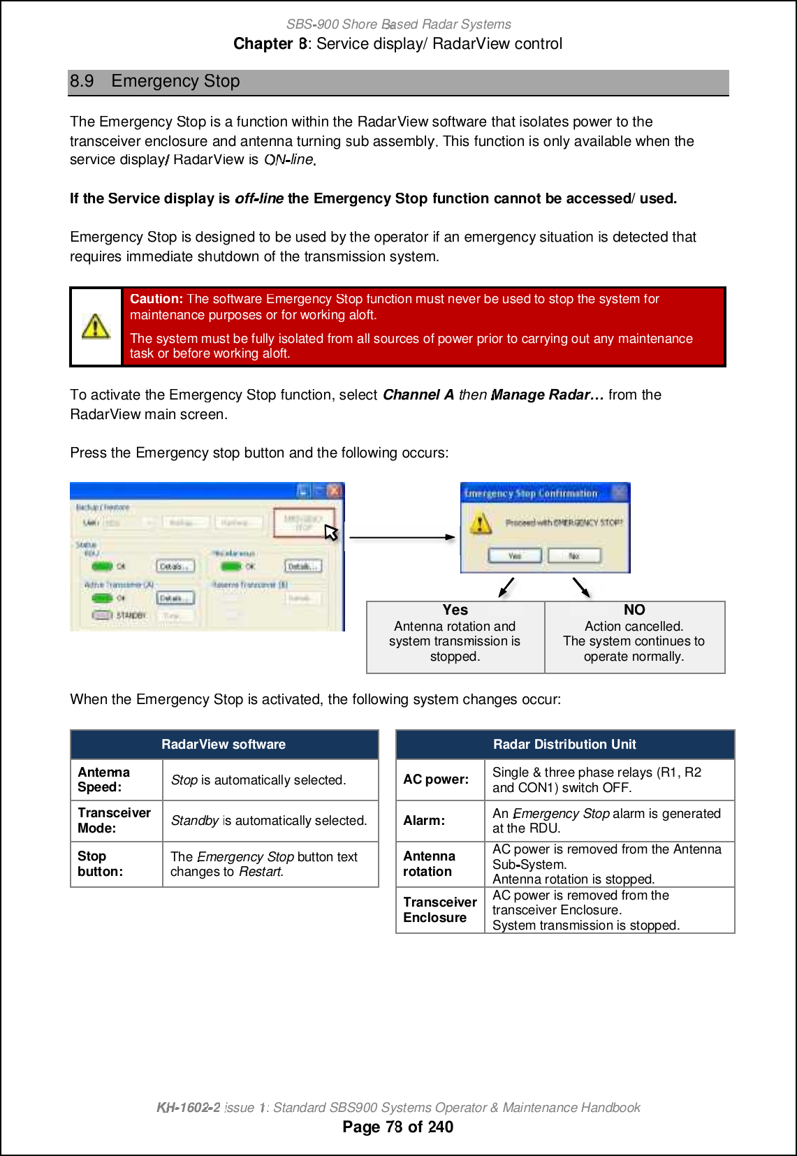
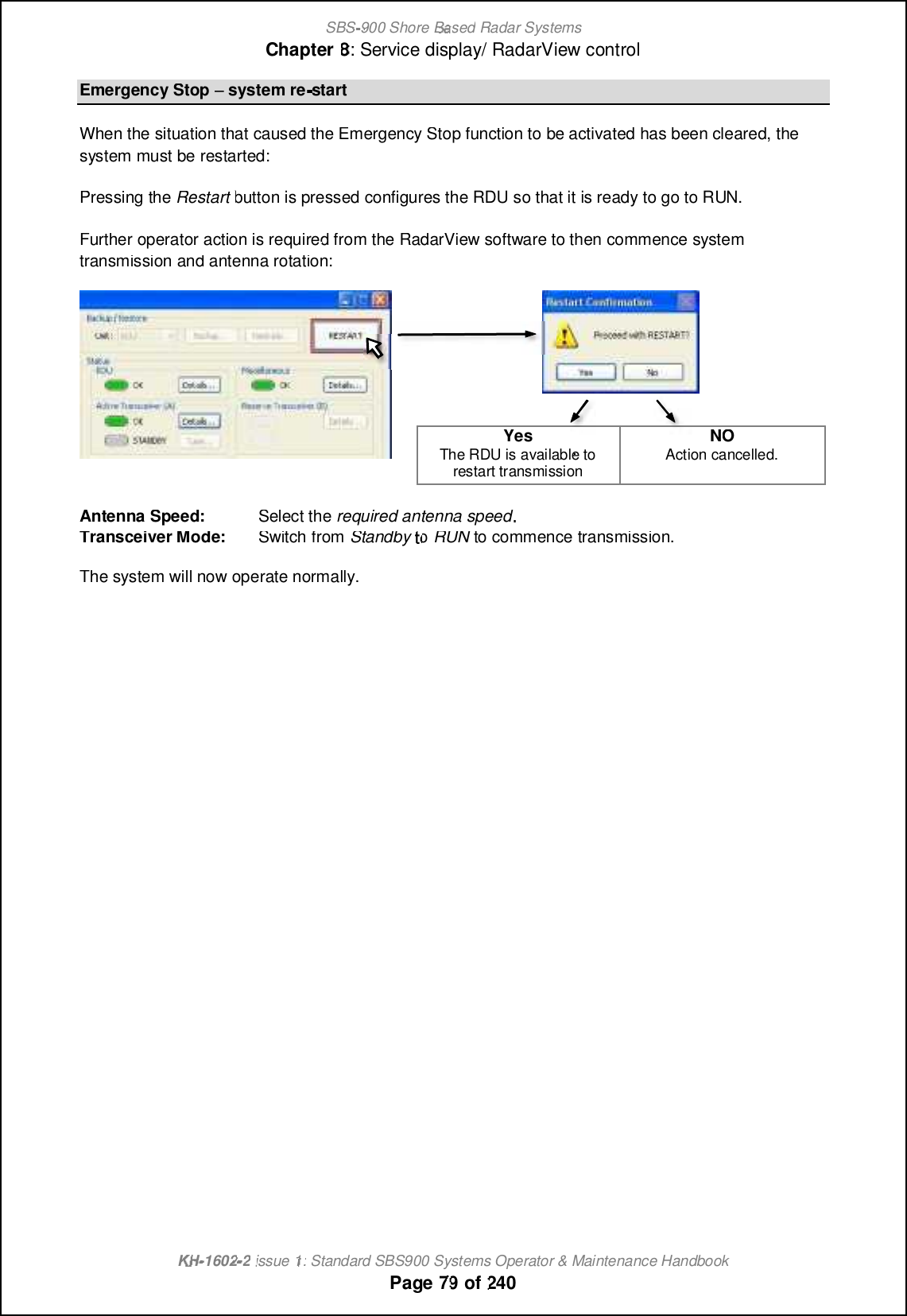
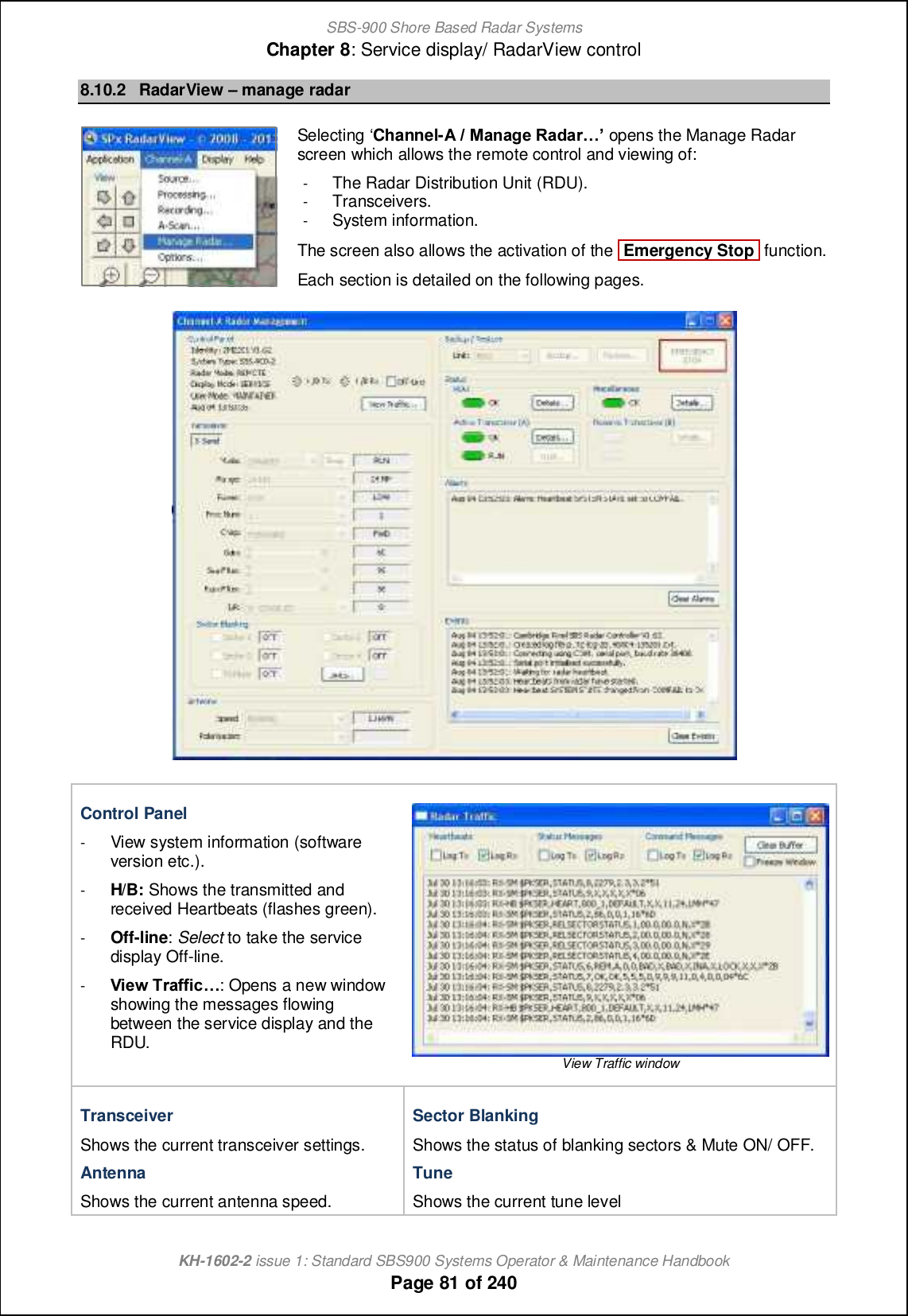
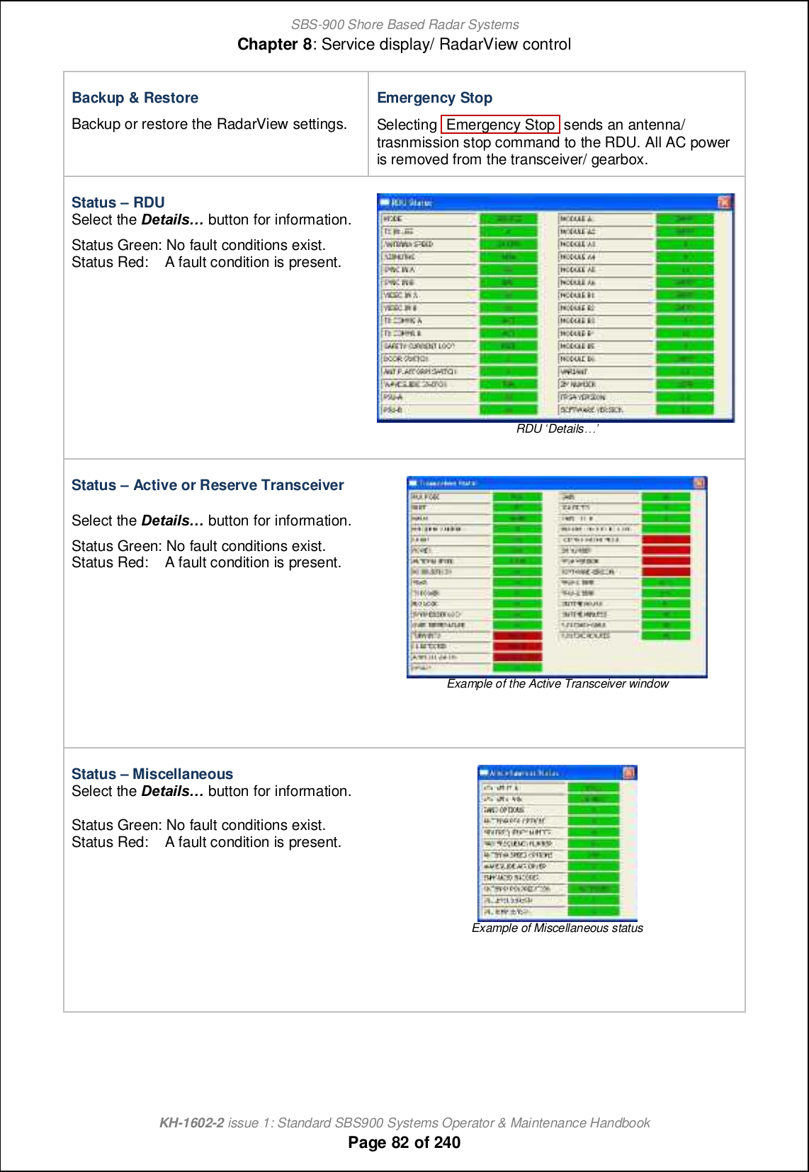
![SBS-900 Shore Based Radar SystemsChapter 8: Service display/ RadarView controlKH-1602-2 issue 1: Standard SBS900 Systems Operator & Maintenance HandbookPage 80 of 2408.10 RadarView operator overview8.10.1OverviewThe manufactures operator handbook for RadarView can be located as follows:Printed copies In printed copies of this handbook, a copy of the RadarView usermanual can be found in section Annex B.Electroniccopies (PDF) In electronic copies, the RadarView user manual can be found in theroot directory of the KH1600 document (PDF format).Document details andcopyright notice:Cambridge PixelRadarViewuser manualSPx RadarView for Windows User ManualDocument number: CP-25-110-27Kelvin Hughes Ltd is not responsible for the content of theRadarView user manual which remains the copyright of CambridgePixel Ltd.Document reference CP-25-110-27 contains proprietary information that issensitive to the commercial interests of Cambridge Pixel Ltd. The contentsof this document should not be communicated to third parties without theprior written consent of the Company.The following i``_lm [ \lc_` ip_lpc_q i` nb_ Q[^[lUc_q ij_l[nilm m]l__h. Users mustrefer to the manufactures handbook noted above for full instructions.The RadarView application is run by double clicking on the desktop icon; this willopen the main PPI view shown below.Example of RadarView screen for an SBS-900-2 system](https://usermanual.wiki/Kelvin-Hughes/DTX-A3-FDLR/User-Guide-2620132-Page-80.png)

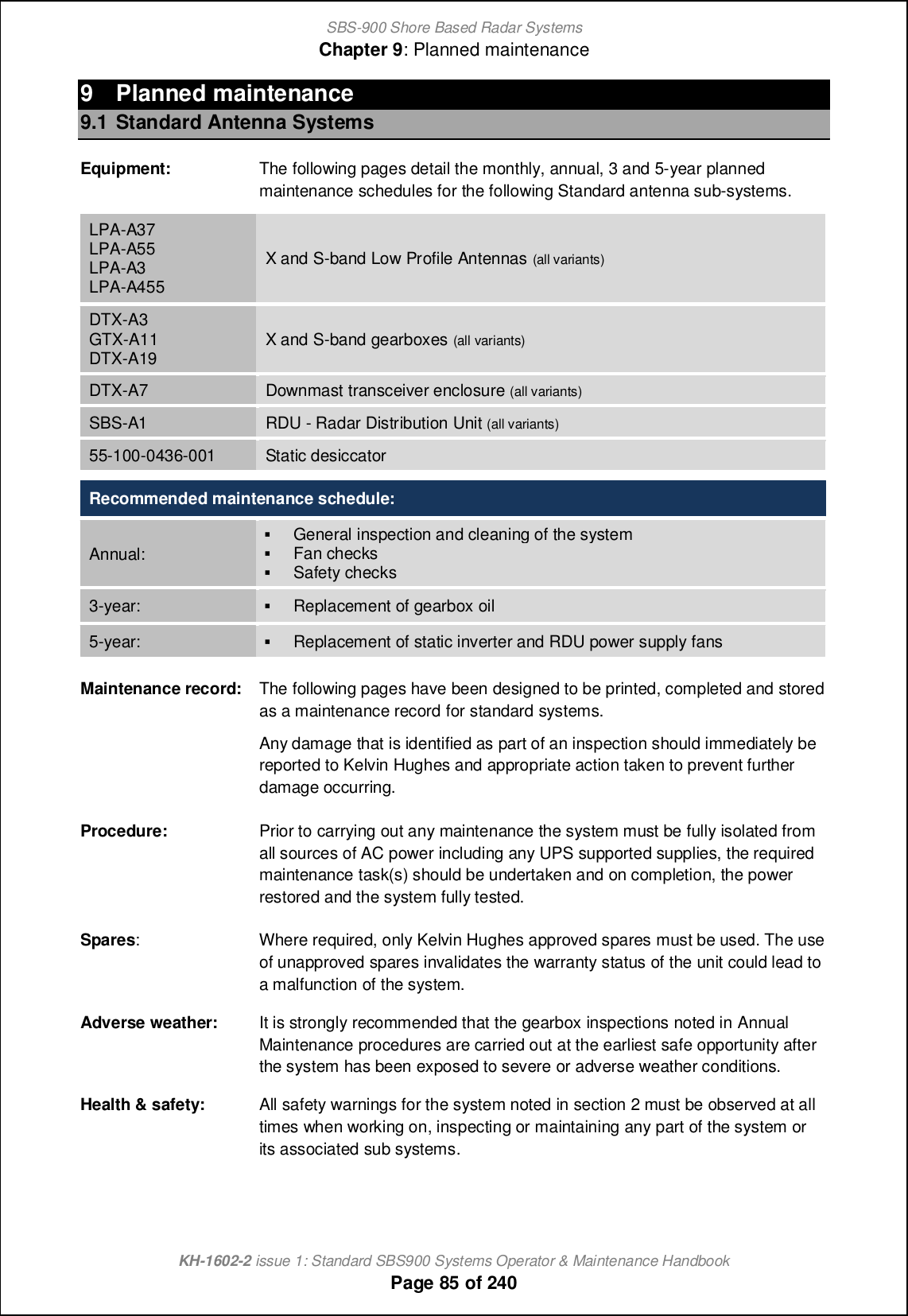
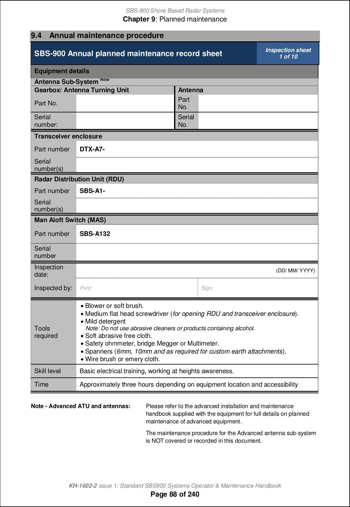
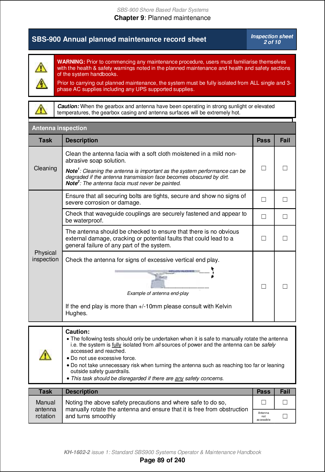
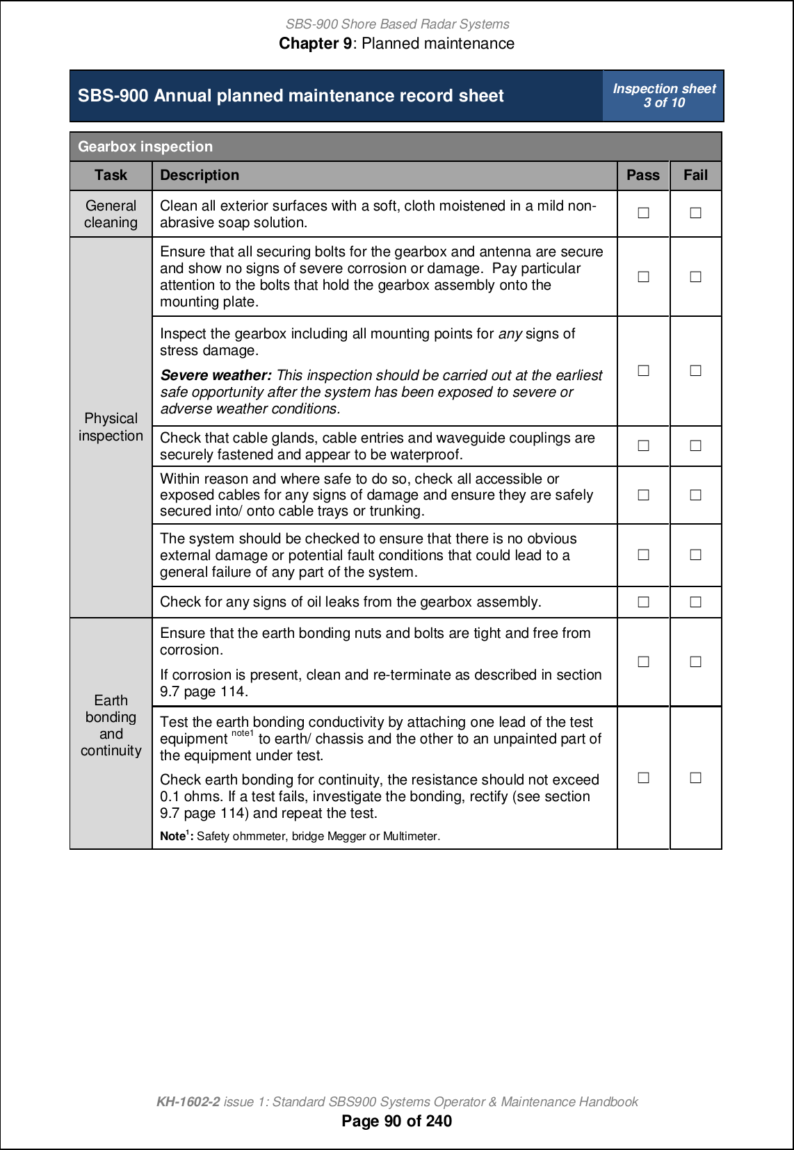
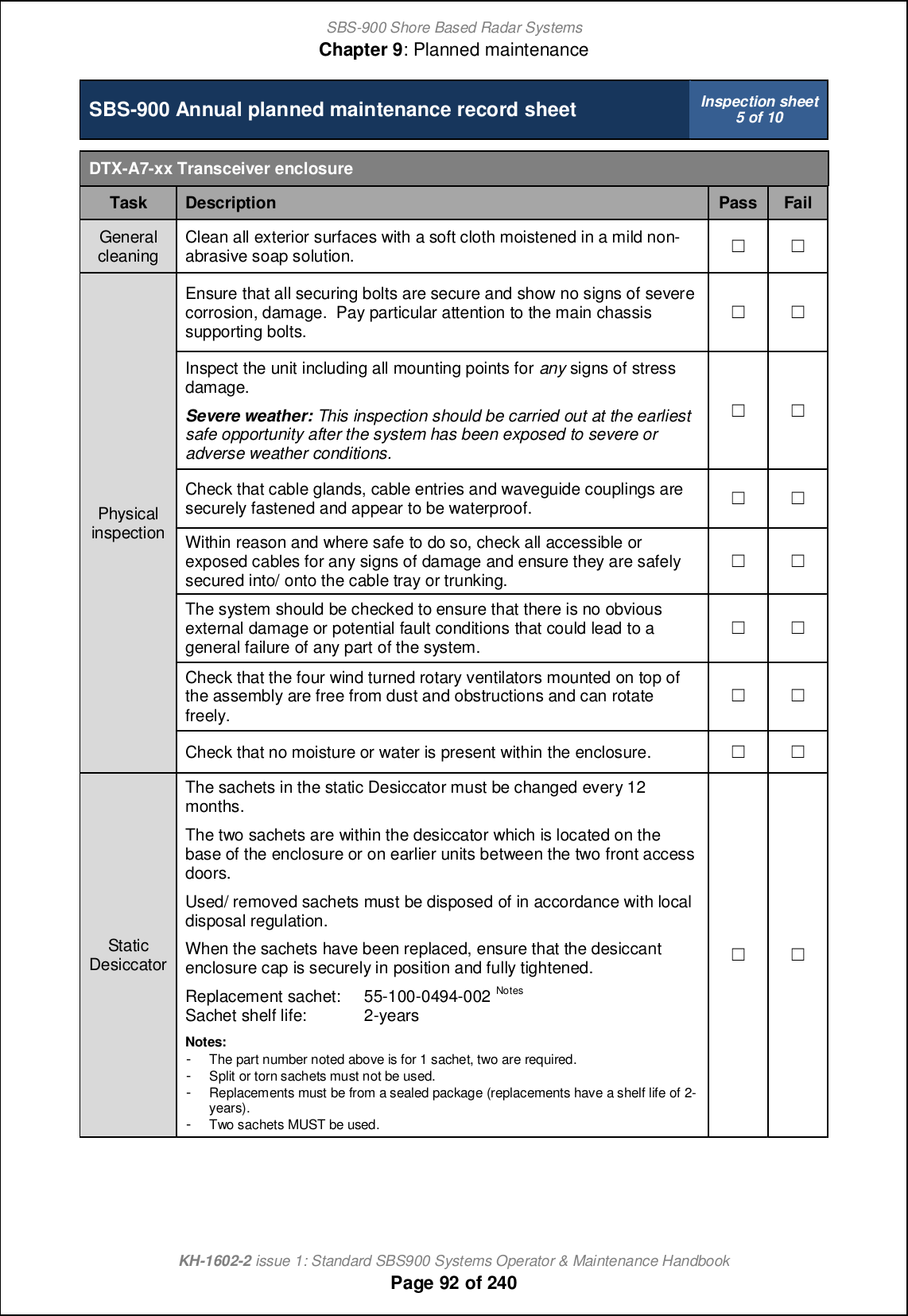
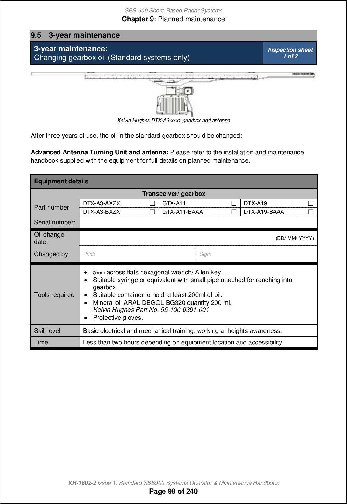
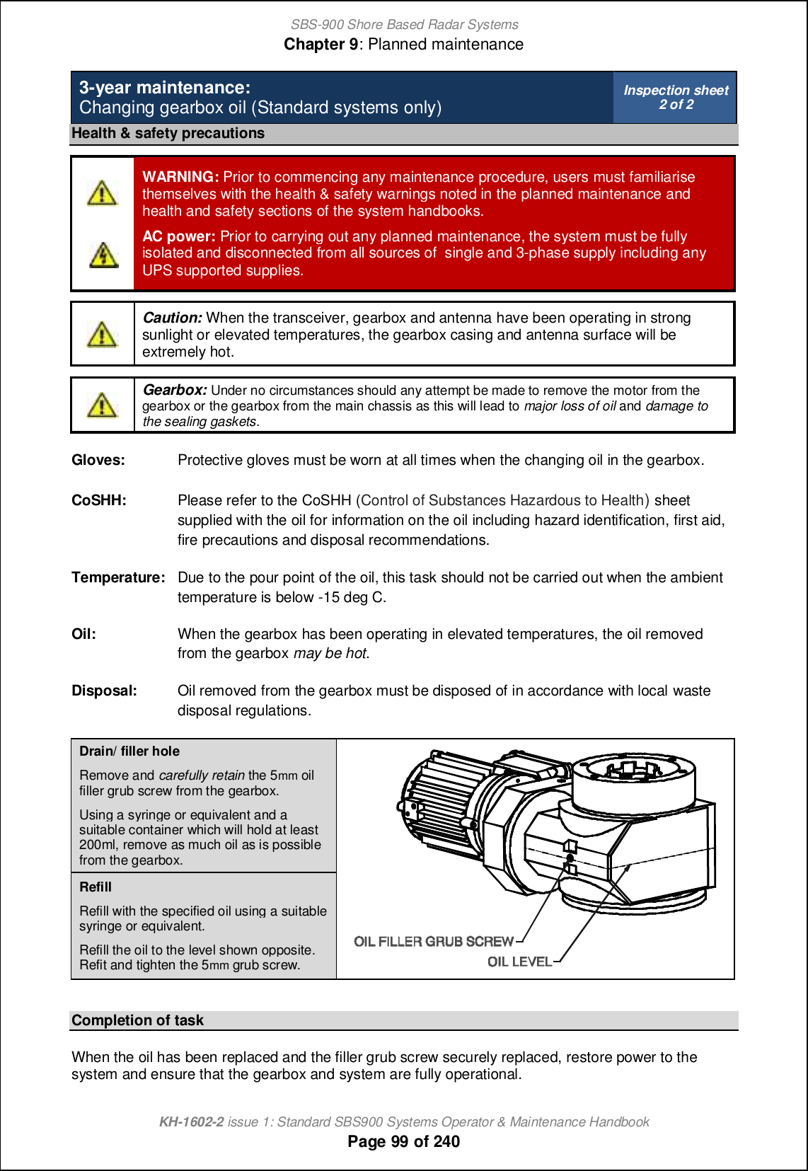
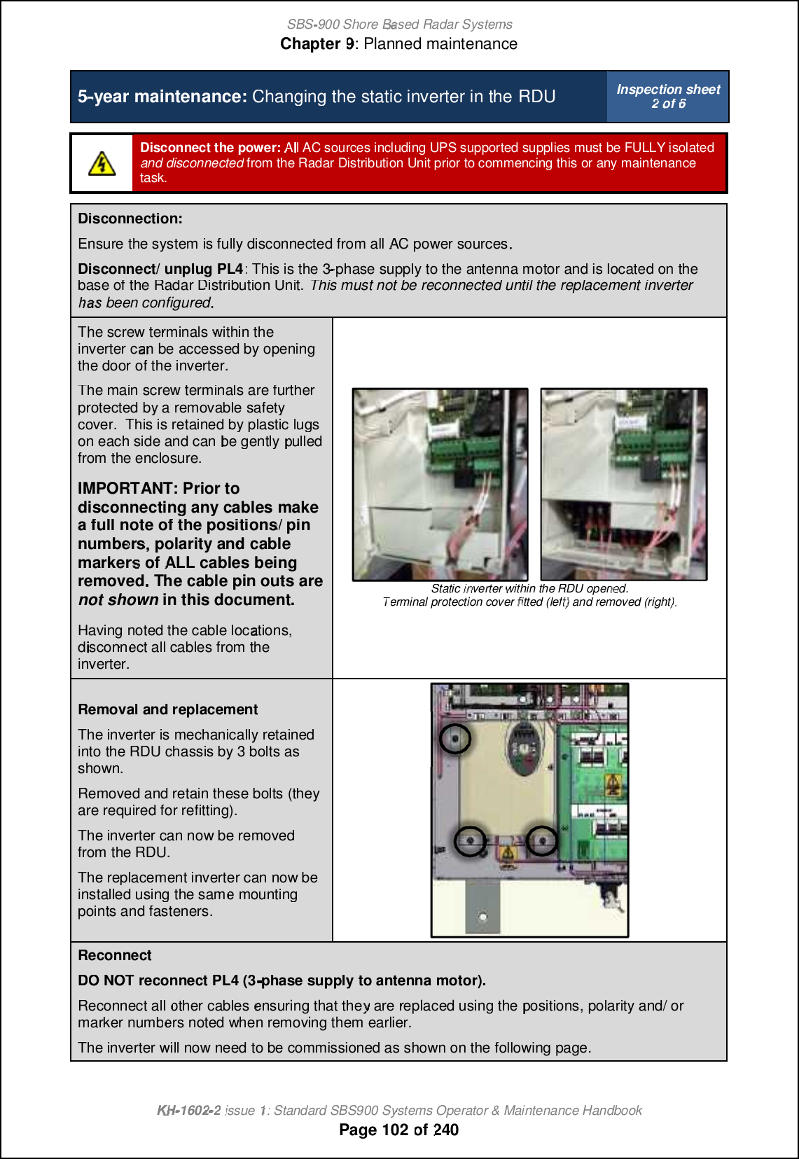
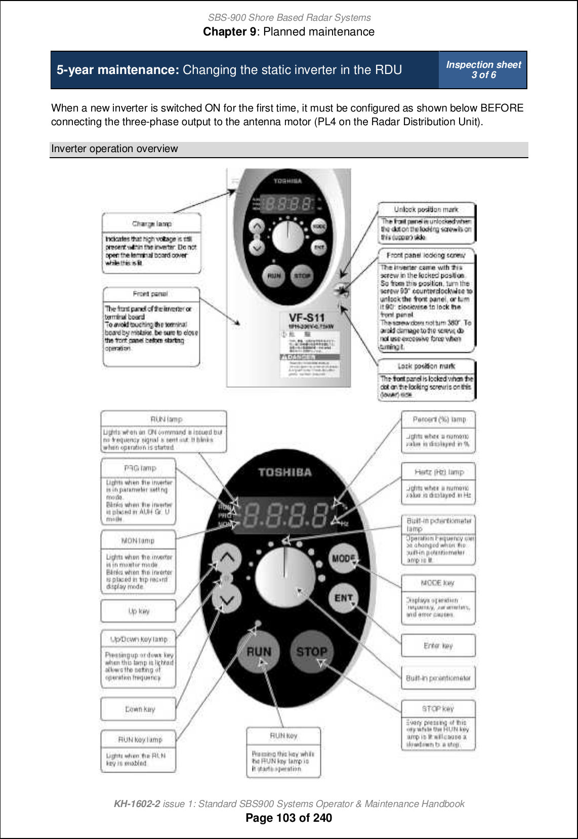
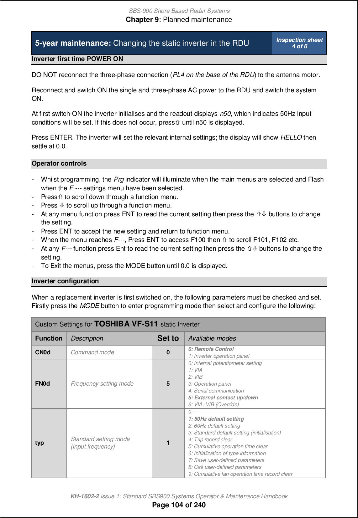
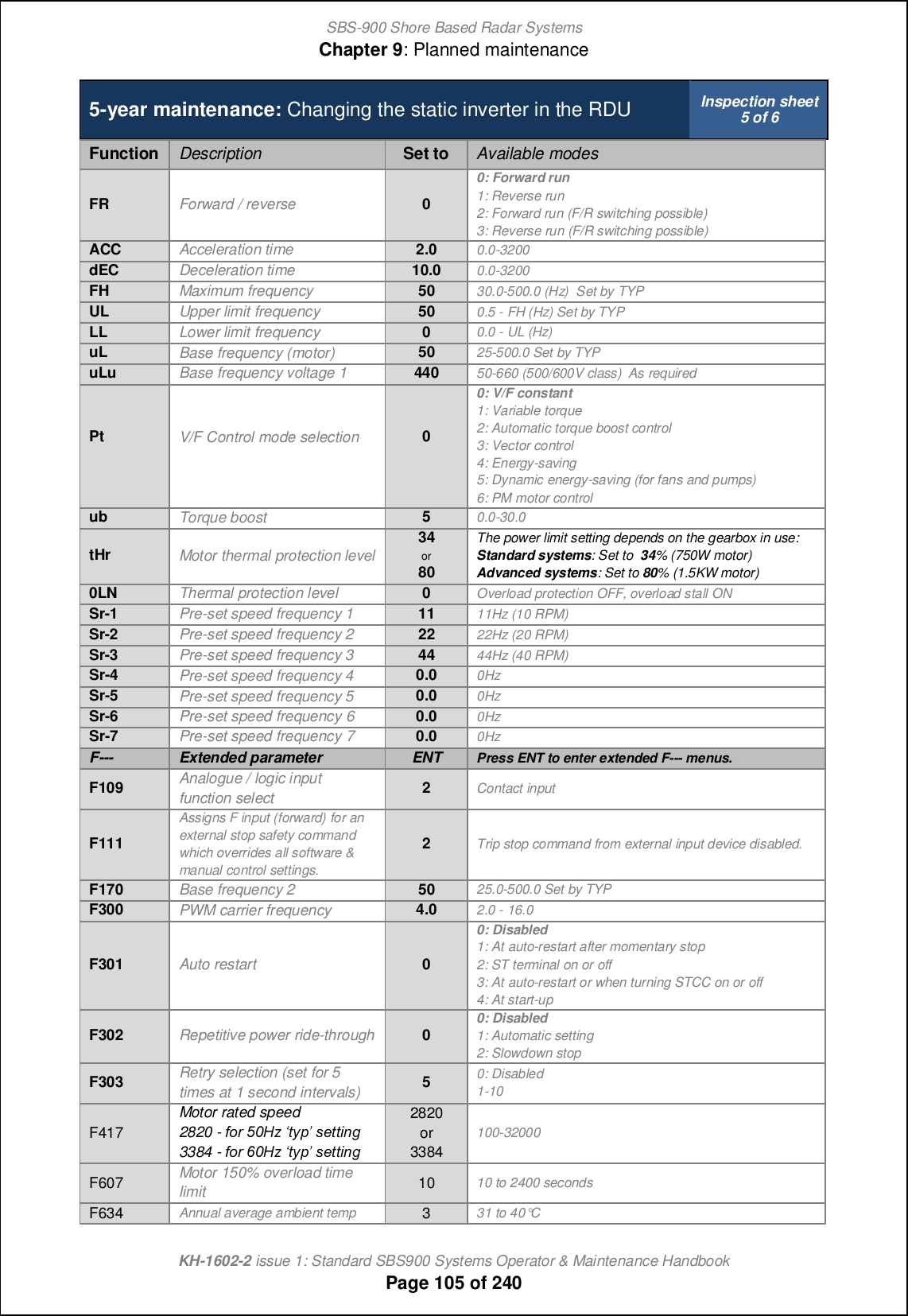
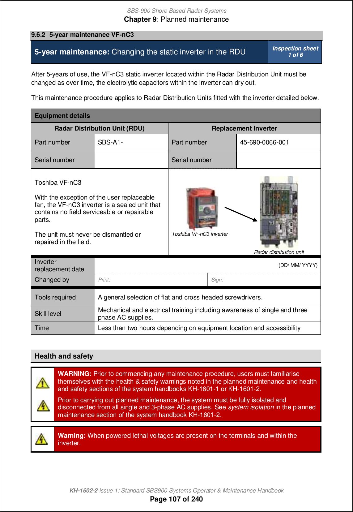
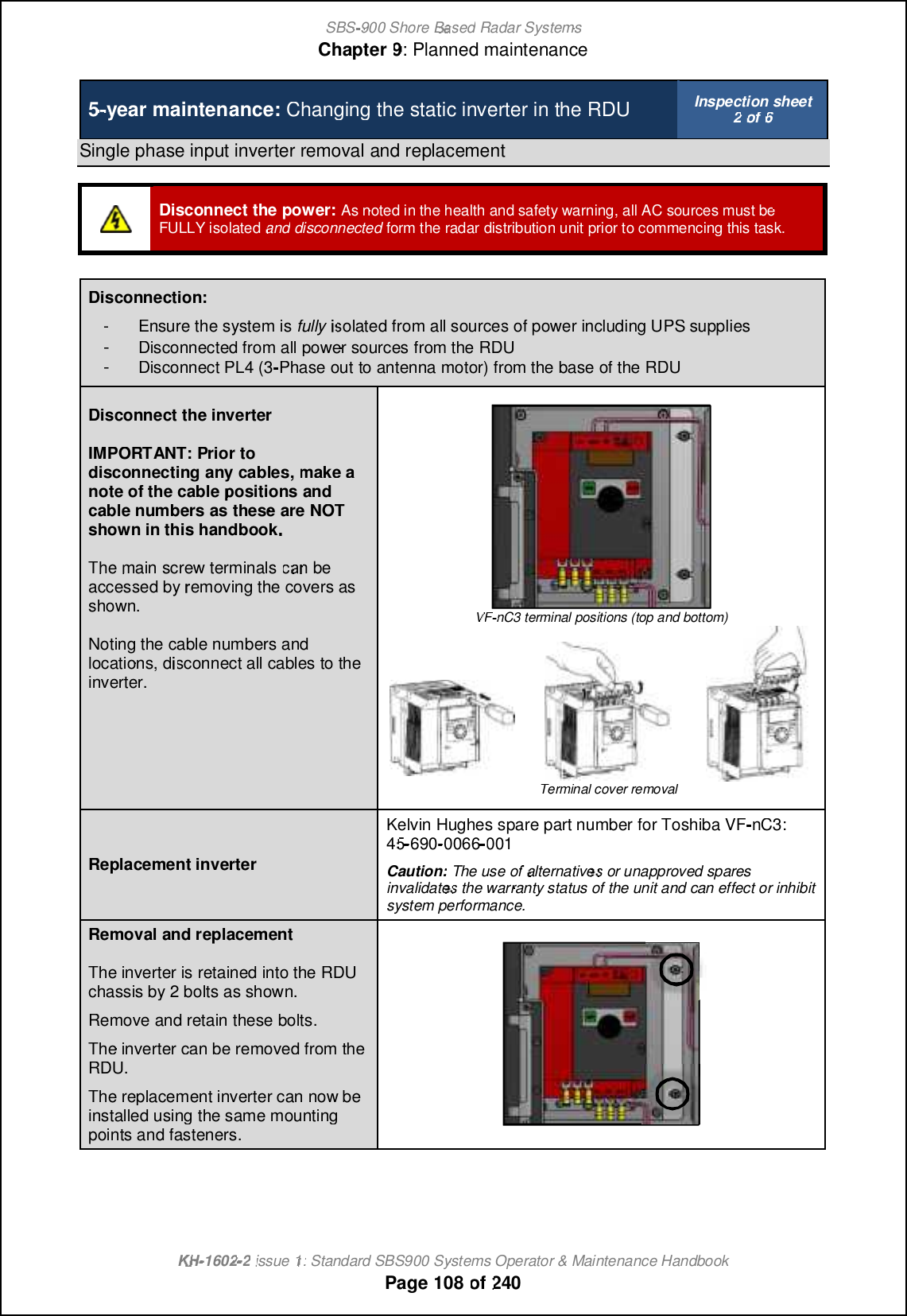
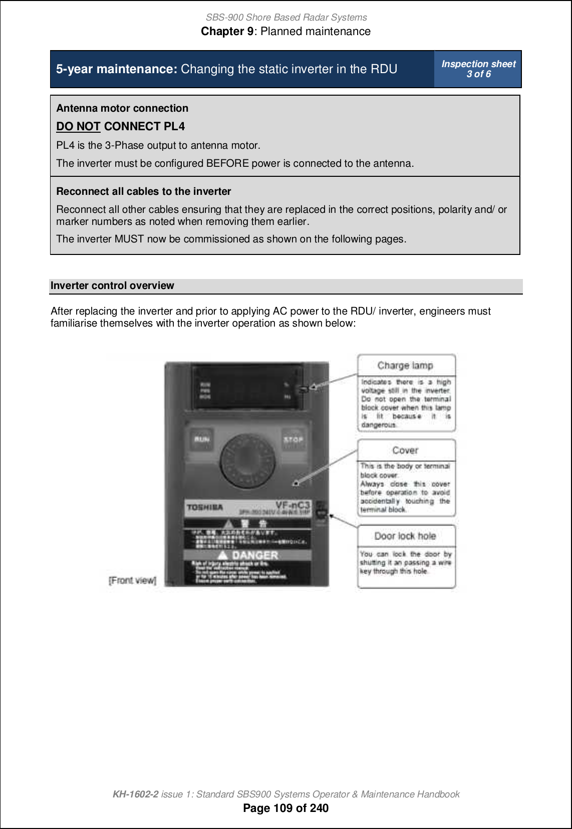
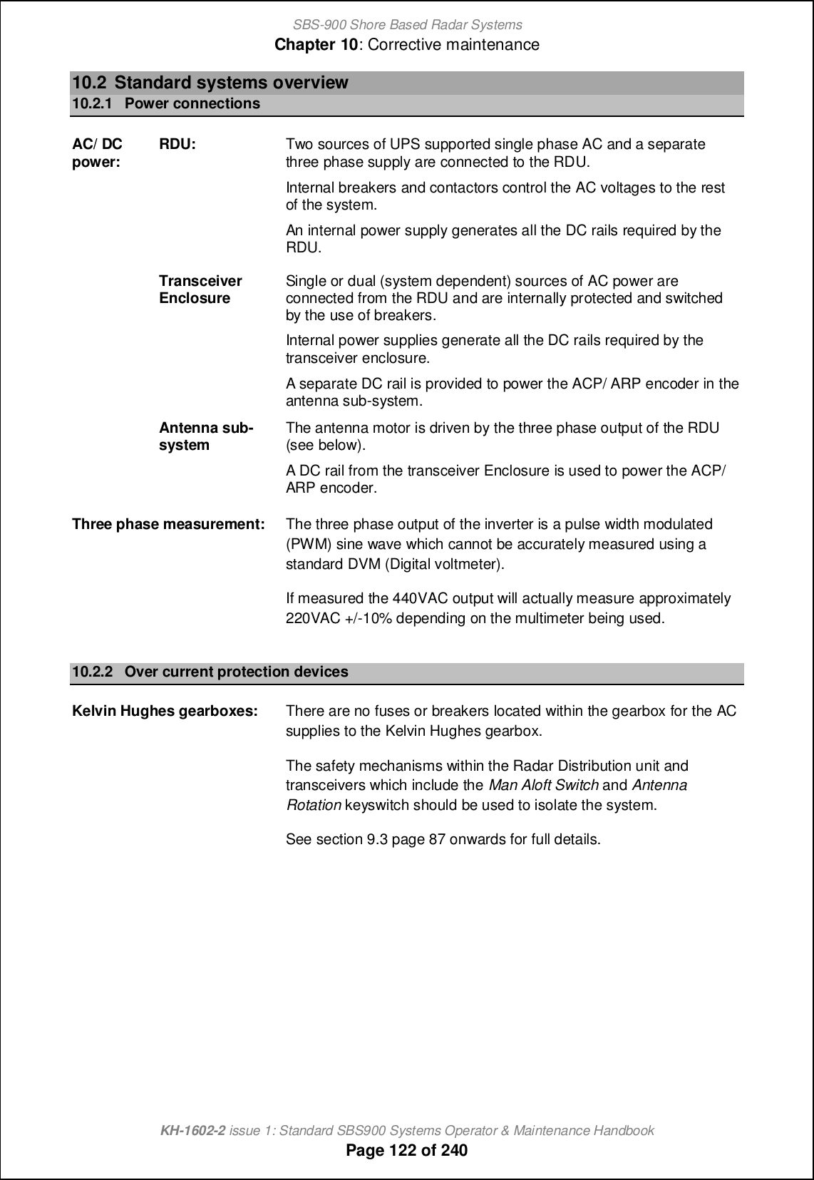
![SBS-900 Shore Based Radar SystemsChapter 9: Planned maintenanceKH-1602-2 issue 1: Standard SBS900 Systems Operator & Maintenance HandbookPage 87 of 2409.3 System isolationIn addition to the normal health and safety requirements, the system must be made safe prior tocarrying out any maintenance task by fully isolating all AC power including any UPS supportedsupplies to the system as shown below:Man aloftswitch(MAS)As an additional safety precaution, the Man Aloft Switchcan be placed into the OFF position.This acts as a backup safety measure to removing theAntenna Rotation keyswitch.RDUAntennarotationswitchPlace the Antenna Rotation keyswitch on the front of theRadar Distribution Unit into the OFF position.The key should be removed and retained until themaintenance task being undertaken has been completed.DTX-A7TransceiverenclosureEnsure that the AC breaker(s) located within thetransceiver enclosure are in the OFF position.Note: Sb_ KDCm ih _[]b \l_[e_l [l_ cffogc[n_^ qb_h @B supplies are still connected to the transceiver enclosure.RDUAC powerWithin the Radar Distribution Unit, ensure allbreakers are in the OFF position.Note: Vb_h mqcn]b_^ NEE+ nb_ KDCm ih _[]b breaker remain illumiated indicating that ACsupplies are still connected to the RDU.External ACIsolate and disconect ALL single and 3-phase AC supplies to the RadarDistribution Unit including all UPS supported supplies and physically remove allpower sockets.The system is now fully isolated from all sources of AC supply.](https://usermanual.wiki/Kelvin-Hughes/DTX-A3-FDLR/User-Guide-2620132-Page-87.png)
![SBS-900 Shore Based Radar SystemsChapter 9: Planned maintenanceKH-1602-2 issue 1: Standard SBS900 Systems Operator & Maintenance HandbookPage 91 of 240SBS-900 Annual planned maintenance record sheet Inspection sheet4 of 10Radar Distribution unit (RDU)Task Description Pass FailCleaningExternalsurfaces Clean with a soft, non-abrasive cloth moistened in a mildsoap solution. ' 'InternalsurfacesOpen the door of the Radar Distribution Unit using ascrewdriver. Carefully clean out the unit using blowerand/ orsoft brush.' 'PhysicalinspectionExternalEnsure that all mounting bolts are secure. ' 'Ensure all connectors are securely in place; inspectinternal cabling for condition and wear. ' 'Check that all air vents are clear of obstructions anddust. ' 'InternalDhmol_ [ff OBAm [h^ ]ihh_]nilm [l_ m_]ol_fs ch jf[]_; inspect internal cabling for condition and wear. ' 'Check that all air vents and fans are clear of obstructionsand clear of dust accumulation. ' 'GeneralThe system should be checked to ensure that there is noobvious internal, external damage or potential faultconditions that could lead to a general failure of any partof the system.' 'EarthbondingandcontinuityOn the underside of the RDU, visually inspect the earth terminal fordamage and corrosion.If corrosion is present, clean and re-terminate as described in section9.7 page 114.' 'Check that the earth bonding strap between the RDU door andchassis is present, clean and re-terminate as described in section 9.7page 114.' 'Test the earth bonding conductivity by attaching one lead of the testequipment note1 to earth/ chassis and the other to an unpainted part ofthe equipment under test.Check the earth bonding for continuity, the resistance should notexceed 0.1 ohms. If a test fails, investigate the bonding, rectify andrepeat the test.Note1:Safety ohmmeter, bridge Megger or Multimeter.' '](https://usermanual.wiki/Kelvin-Hughes/DTX-A3-FDLR/User-Guide-2620132-Page-91.png)
![SBS-900 Shore Based Radar SystemsChapter 9: Planned maintenanceKH-1602-2 issue 1: Standard SBS900 Systems Operator & Maintenance HandbookPage 94 of 240SBS-900 Annual planned maintenance record sheet Inspection sheet7 of 10Man aloft switchTask Description Pass FailPhysicalinspection Ensure that all fastenings are secure and show no signs of severecorrosion or damage. ' 'Switchaction Ensure the switch operation is smooth and that both the Free andOFF positions can be selected. ' 'EarthbondingandcontinuityTest the earth bonding conductivity by attaching one lead of the testequipment note1 to chassis/ earth and the other to an unpainted part ofthe equipment under test.Check the earth bonding for continuity, resistance should not exceed0.1 ohms. If test fails, investigate the bonding, rectify and repeat thetest.Note1:Safety ohmmeter, bridge Megger or Multimeter.' '55-100-0436-001 Static desiccatorTask Description Pass FailPhysicalinspectionThe clear wall of the static desiccator unit allows visualinspection of the desiccant condition.As moisture is adsorbed the desiccant colour will changeto either:Deep blue (dry) to pink/white (wet).orOrange (dry) to purple (wet).When 80% of the desiccant material has changedcolour, the unit should be replaced.To prevent moisture from entering the breather hole, theohcn gomn \_ l_jf[]_^ [m mbiqh qcnb nb_ •hih-`cnncha _h^ that contains the breather hole pointing downwards.Maintenance frequency note: In areas of high humidity it may benecessary to increase the inspection period of the desiccant.StaticDesiccator' 'Restore power to the systemOn completion of the above maintenance tasks and noting that the following will cause antennarotation and system transmission, restore power to the system.Securityswitches Place the Antenna rotation and man aloft switches in the FREEpositions.Antennarotation'Man aloft 'ACBreakers Switch the single and three-phase breakers within the RDU ON.Caution: This will cause the antenna to rotate 'Remotecontrol Place the Remote/ Local switch on the RDU to the Local position. 'Test Test the system and ensure full functionality. '](https://usermanual.wiki/Kelvin-Hughes/DTX-A3-FDLR/User-Guide-2620132-Page-94.png)

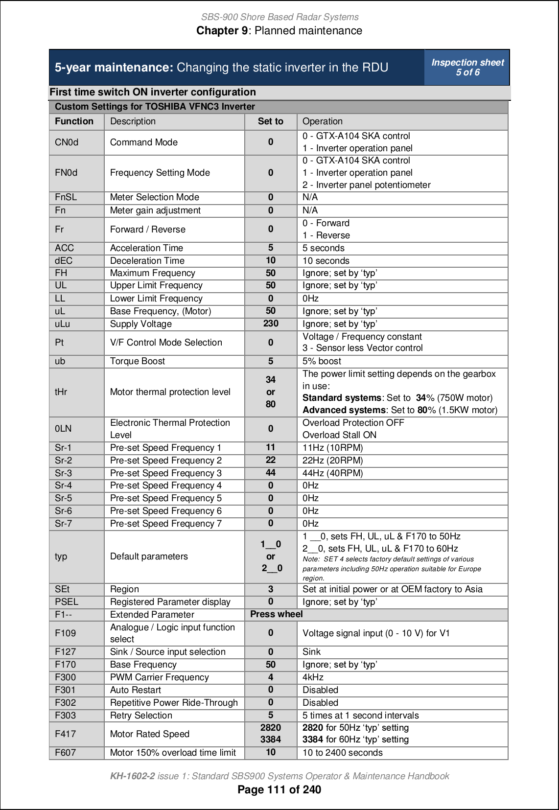
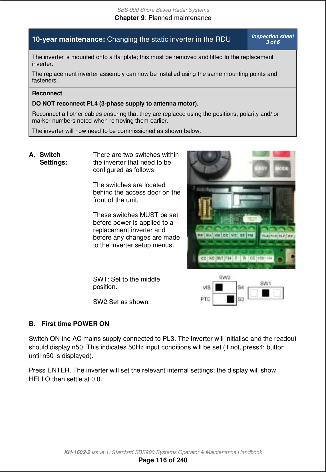
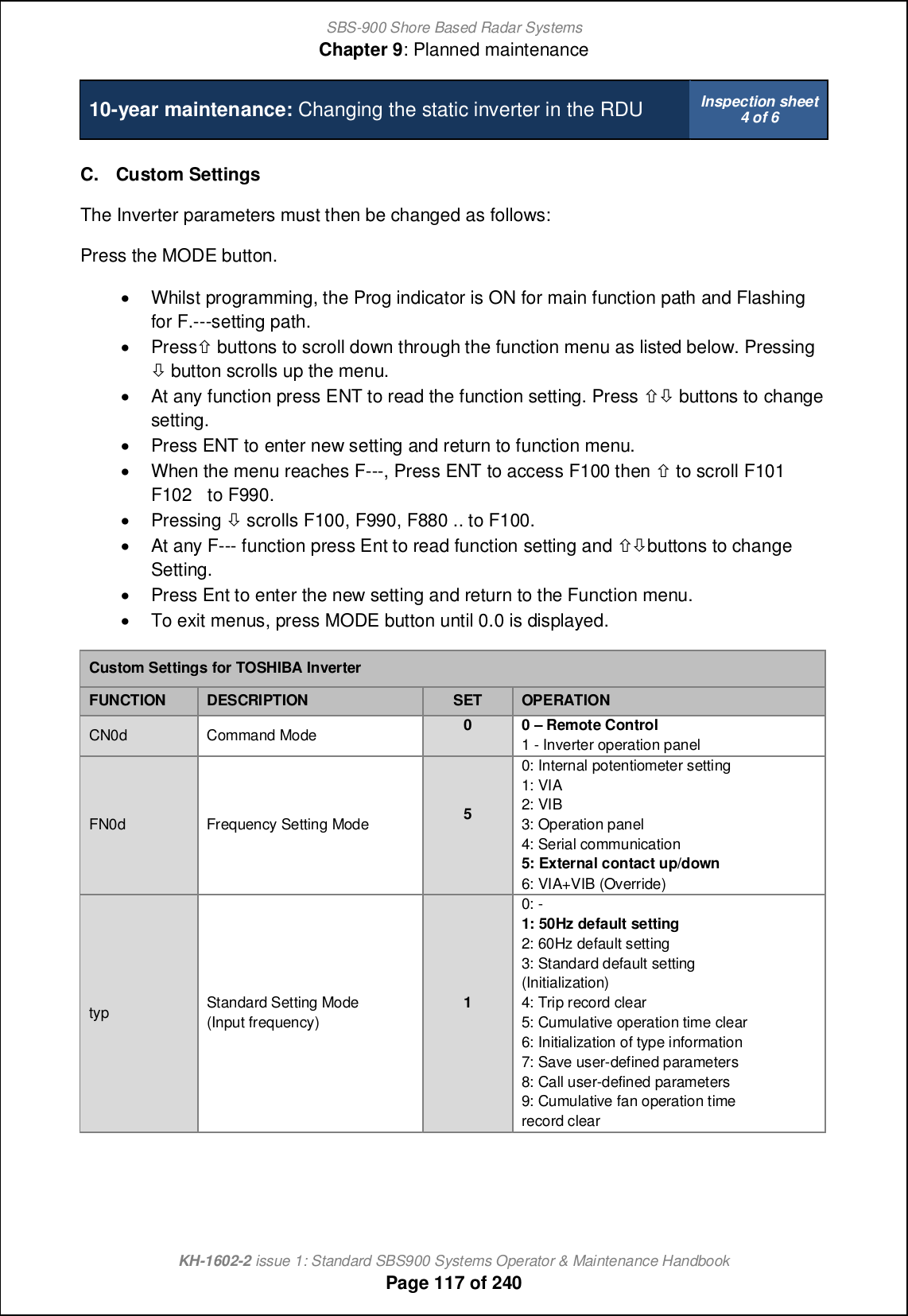
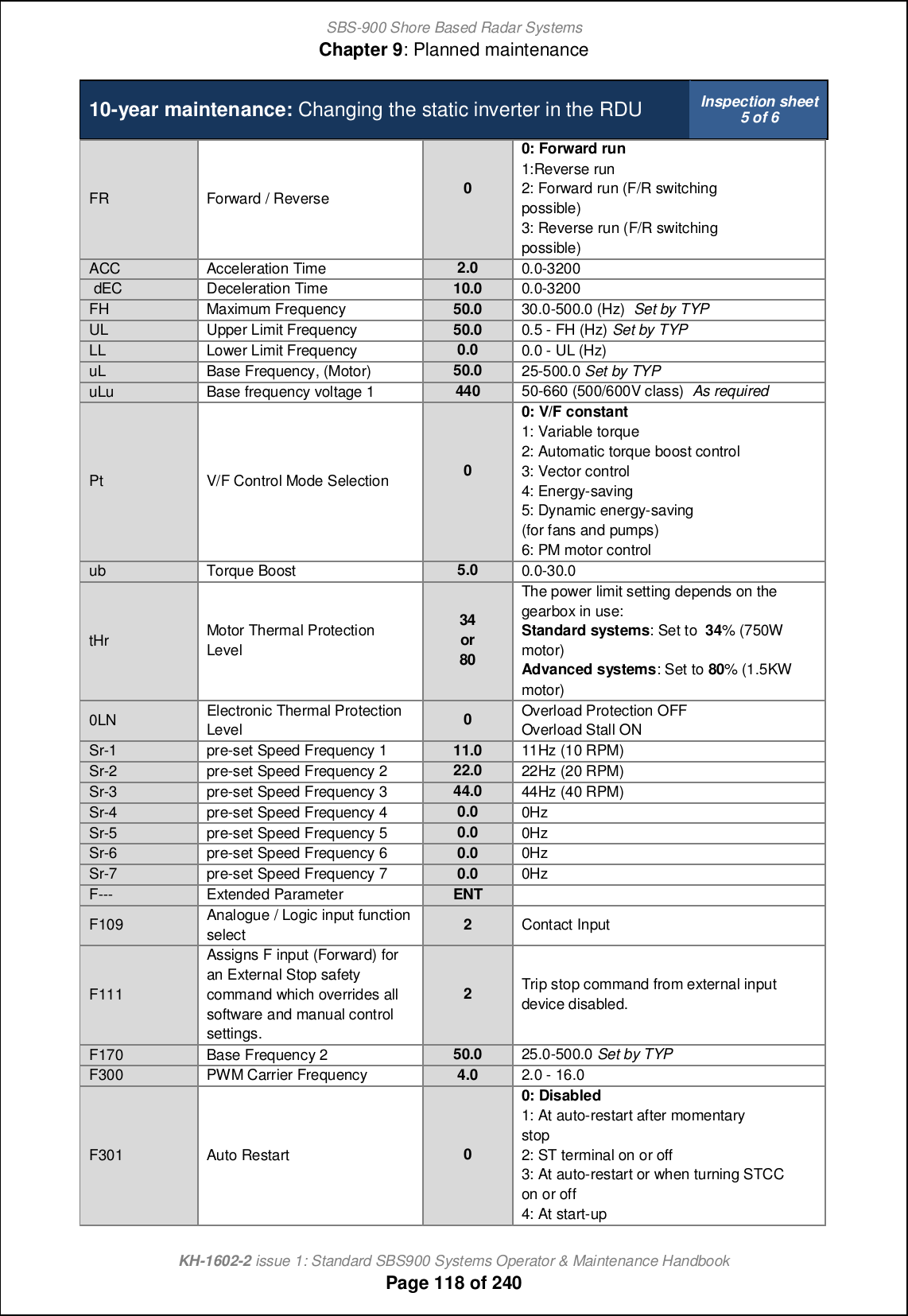
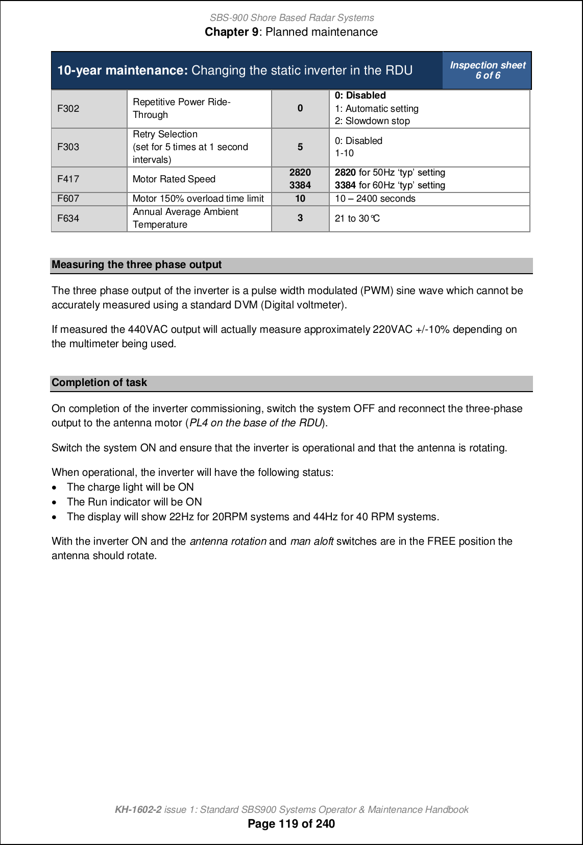
![SBS-900 Shore Based Radar SystemsChapter 9: Planned maintenanceKH-1602-2 issue 1: Standard SBS900 Systems Operator & Maintenance HandbookPage 110 of 2405-year maintenance: Changing the static inverter in the RDU Inspection sheet4 of 6A. First time POWER ONi. With PL/ SK 4 disconnected apply power to the RDU.ii. The inverter initialises and the display will show HELLO then settle at 0.0.B. Region Settingi. If the display is flashing SEt, then a region code has to be entered.ii. Rotate the wheel to ASIA and press wheel to set, (init will appear) display should now be 0.0.iii. If Set is not flashing it is necessary to restore the inverter back to the factory default setting priorto entering a new region code.iv. Ol_mm LNCD [h^ \s `iffiqcha nb_ aoc^[h]_ \_fiq m_n nsj ni 02- @`n_l l_m_n+ m_n nb_ l_acih code to ASIA as detailed above.C. Custom SettingsThe Inverter parameters must then be changed as follows:i. Press MODE, AUH should appear, then rotate wheel to CnOd and press wheel to set parameteras shown in the following page. (Pressing the wheel after each setting should advance to nextfunction).ii. Rotate the wheel clockwise to scroll down through the function menu as listed below. Rotatingthe wheel counter clockwise will scroll up the menu.iii. At any function press the wheel to read the function setting. Rotatewheel to change setting.iv. Press the wheel to enter a new setting and return to function menu.v. To exit menus, press STOP button (4 times) until 0.0 is displayed](https://usermanual.wiki/Kelvin-Hughes/DTX-A3-FDLR/User-Guide-2620132-Page-110.png)

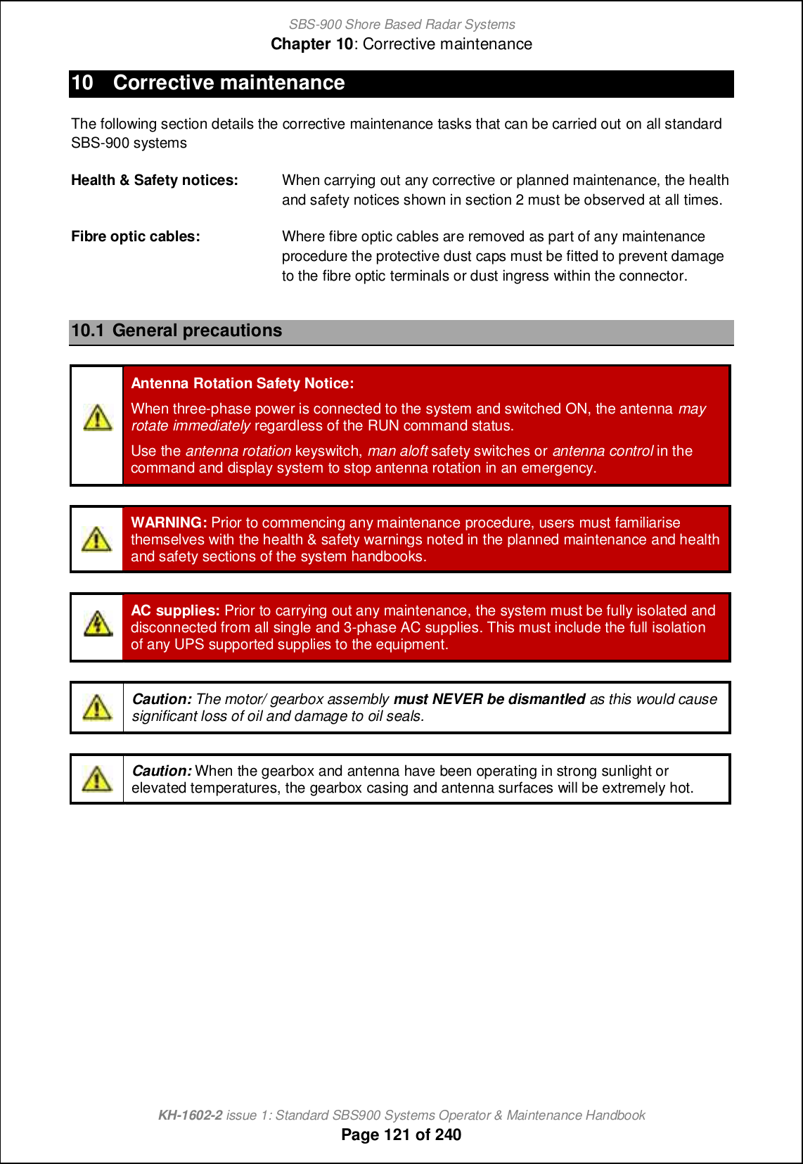
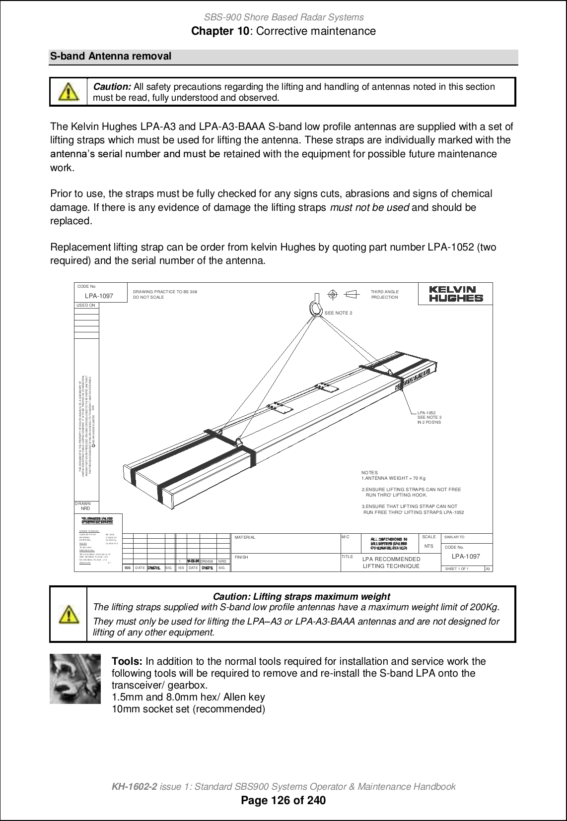
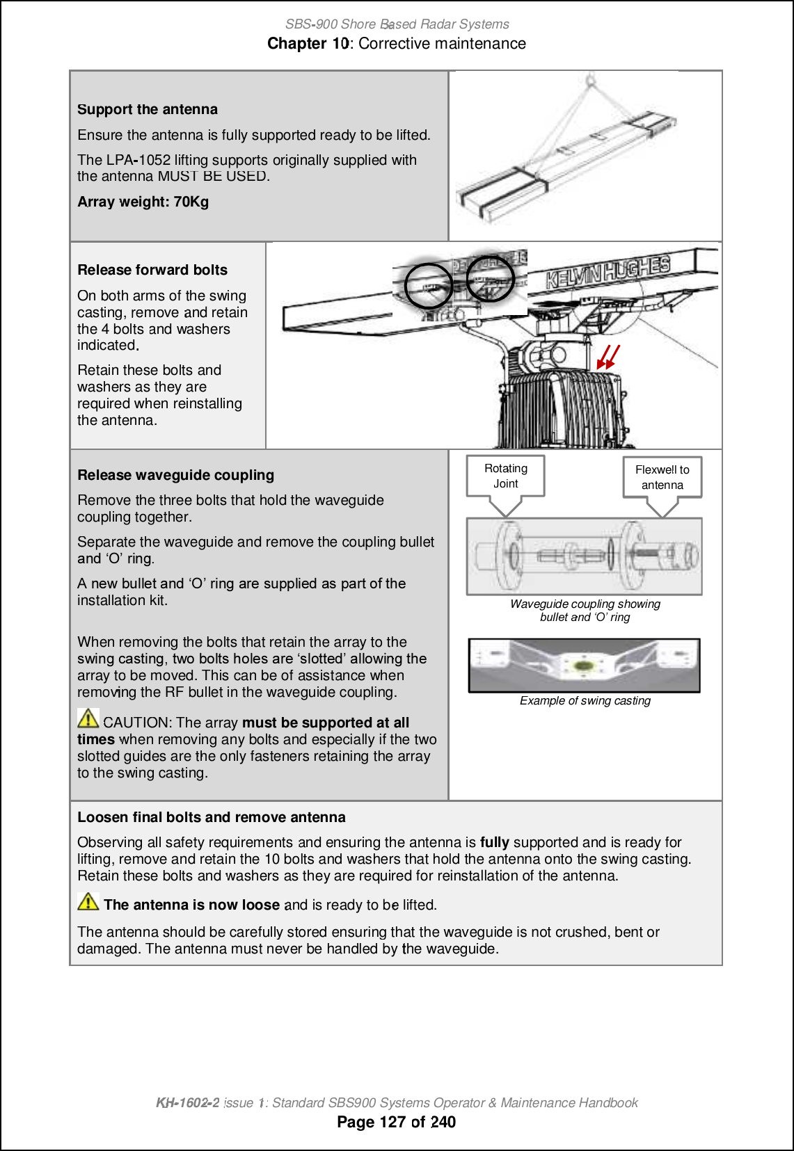
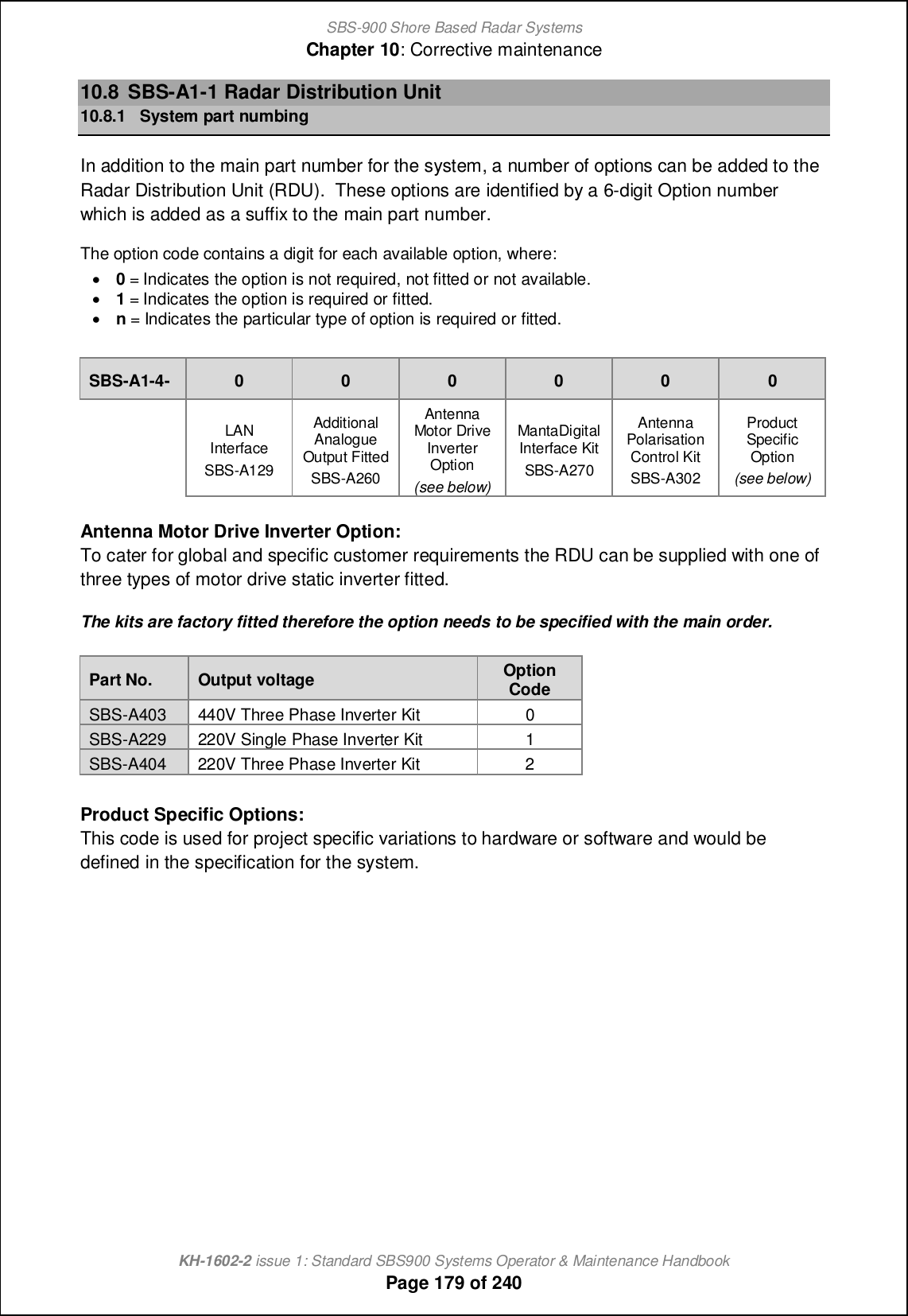
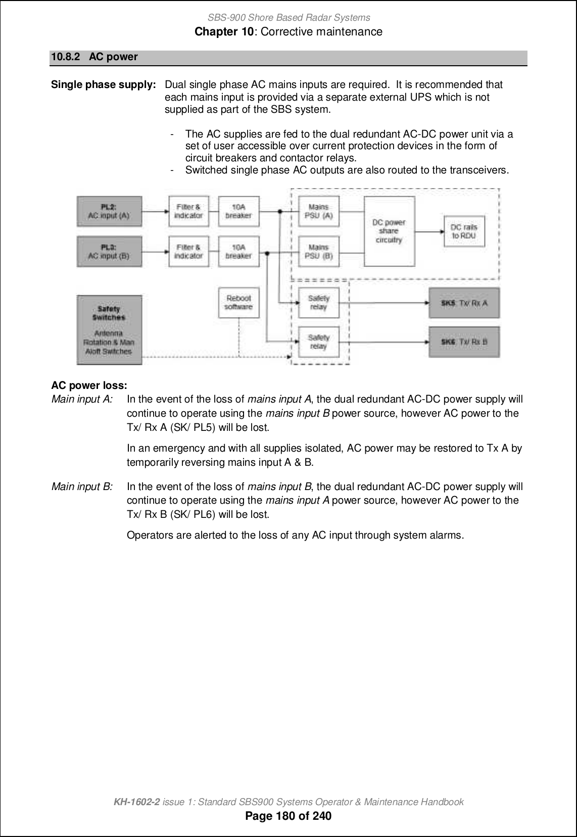
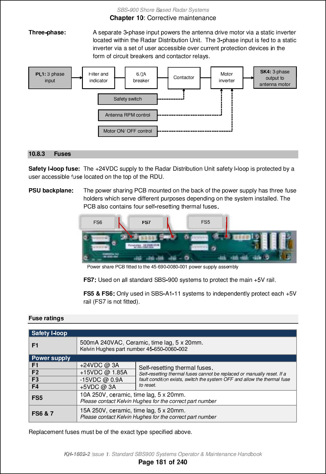
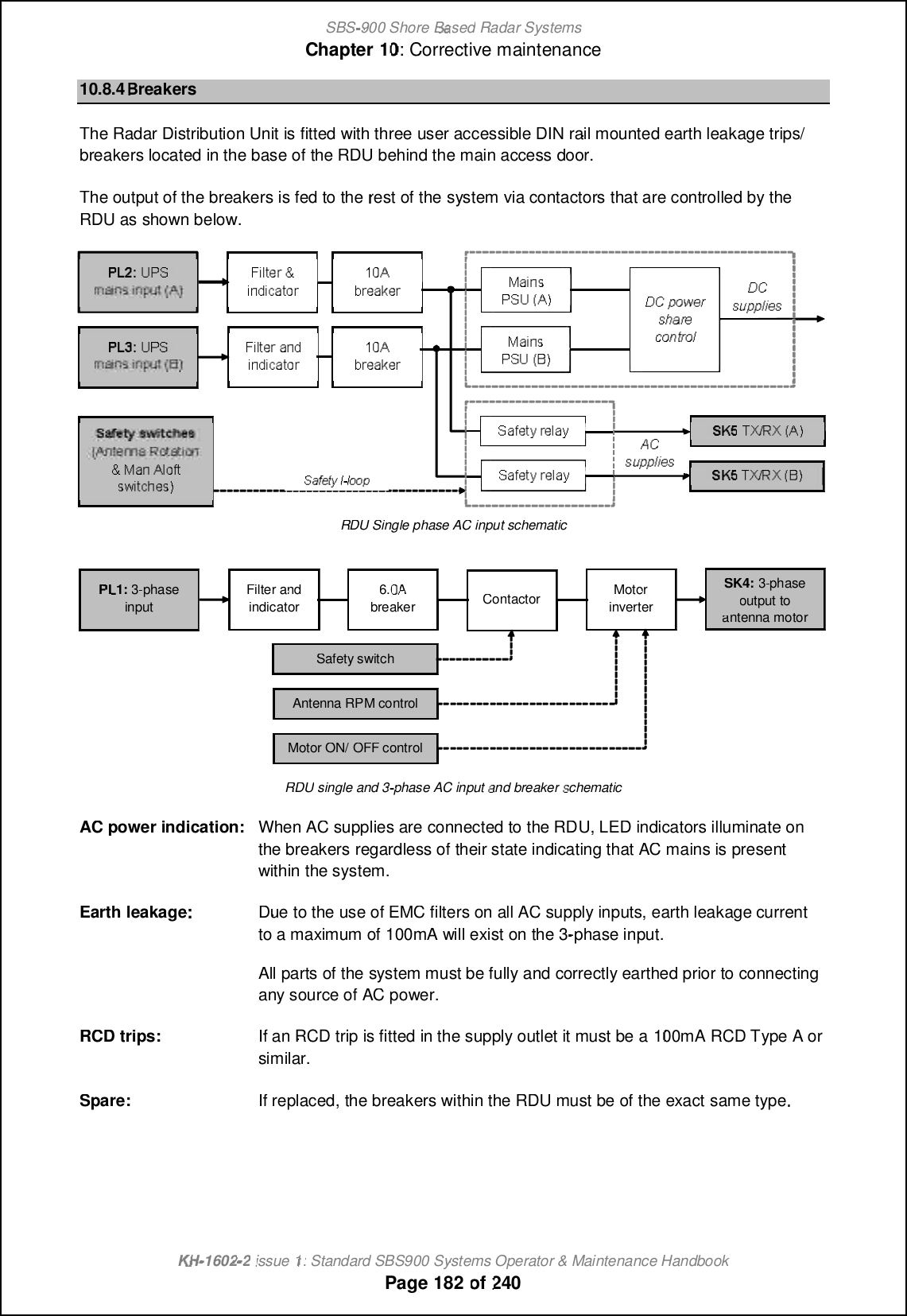
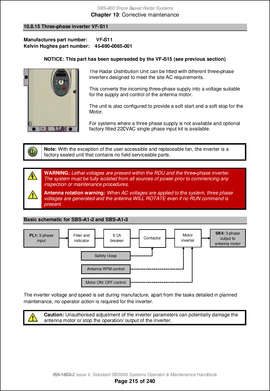
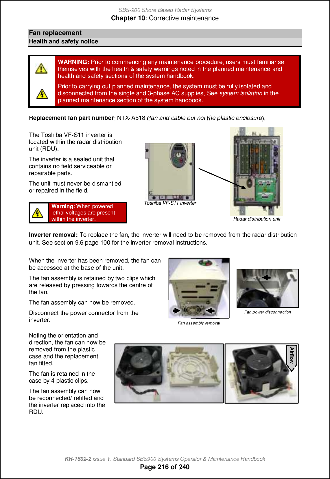
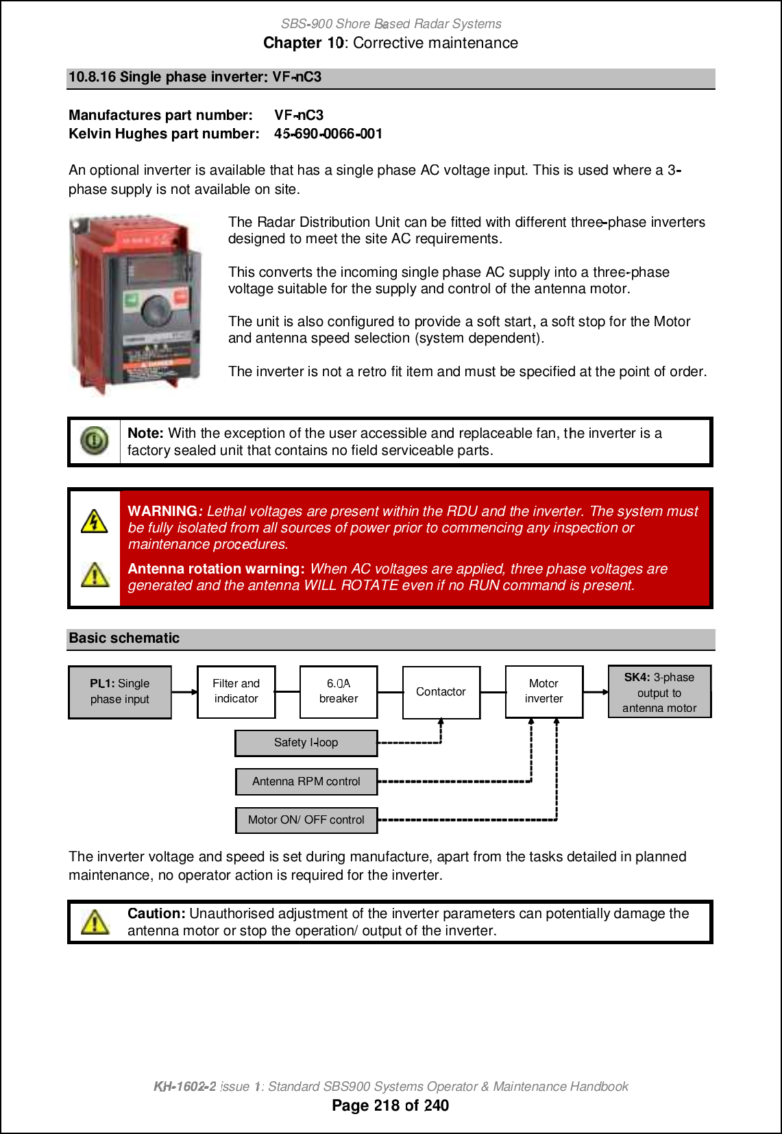
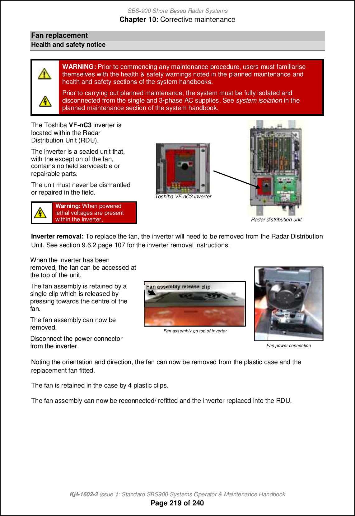
![SBS-900 Shore Based Radar SystemsChapter 10: Corrective maintenanceKH-1602-2 issue 1: Standard SBS900 Systems Operator & Maintenance HandbookPage 124 of 24010.2.4 Antenna removalThe Low Profile Antenna will need to be removed and temporarily stored for some maintenance tasks.The lifting procedures are listed below.Where an antenna is to lifted, all safety and lifting requirements noted in below must be read,understood and fully observed.WARNING:Antennas are heavy items and must be lifted using suitable liftingequipment, a secured block and tackle or by rope strops.CAUTION: During removal and installation, the antenna must be secured and supportedat all times to prevent any risk of falling or slipping.Antennas must never be left unsupported on the swing casting.'All health and safety requirements must be checked and observed at all times when lifting anyequipment. All appropriate personal protective equipment (PPE) must be worn.'Where special equipment such as cranes hoists and jigs is required, consideration must be givento the authority to use such equipment.'During lifting, a safety zone shall be established beneath the lifting area around any cranes orplatforms. Safety personnel must ensure that persons do not encroach on the area of work.'Consult with the lifting operator to obtain the best and safest method of securing lifting strops orropes to the equipment and advise lifting operators of the areas of a system that are susceptible to^[g[a_ mo]b [m [hn_hh[ `[m]c[m+ mqcha ][mncham _n]-'Check that the centre of gravity of the equipment cannot cause the lifting strops or ropes to slip ormove.'All straps, lifting cables or ropes must be thoroughly checked to ensure that there is no risk of theunit slipping or falling from the lifting strap or lifting equipment.'If lifting a transmitter/ gearbox with the antenna pre-assembled, the lifting equipment, ropes orstraps must not place any pressure on any part of the antenna or the swing casting.'Kelvin Hughes cannot be held responsible for any damage that occurs to supplied or 3rd partyequipment as a result of incorrect lifting procedures or handling or equipment.](https://usermanual.wiki/Kelvin-Hughes/DTX-A3-FDLR/User-Guide-2620132-Page-124.png)

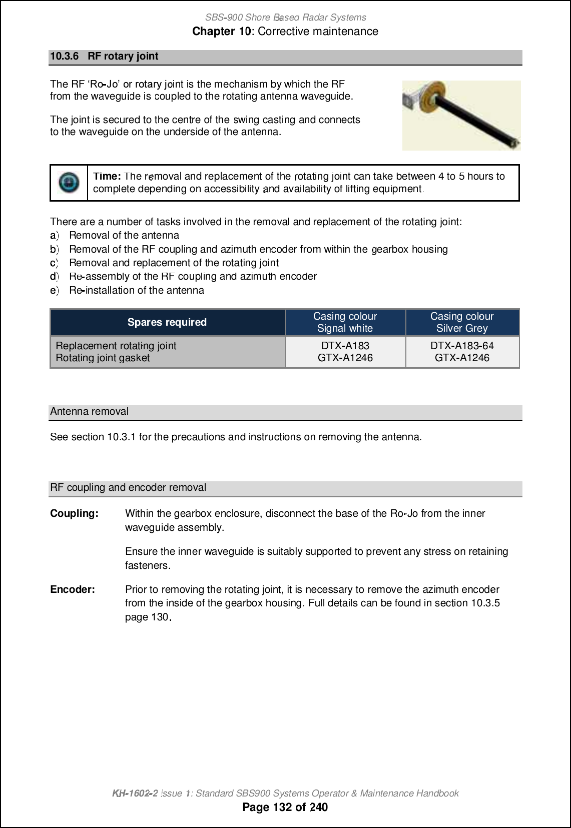
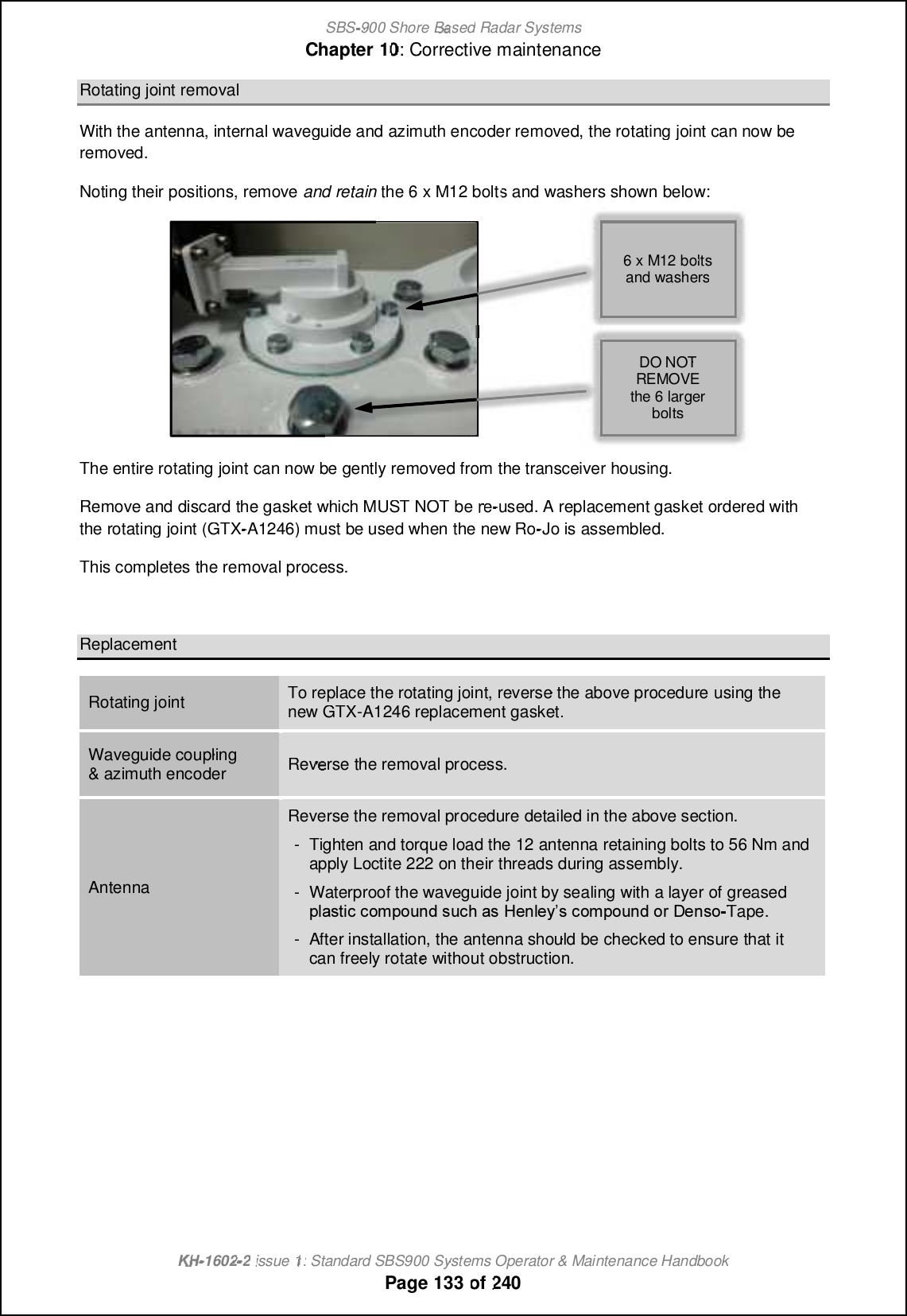

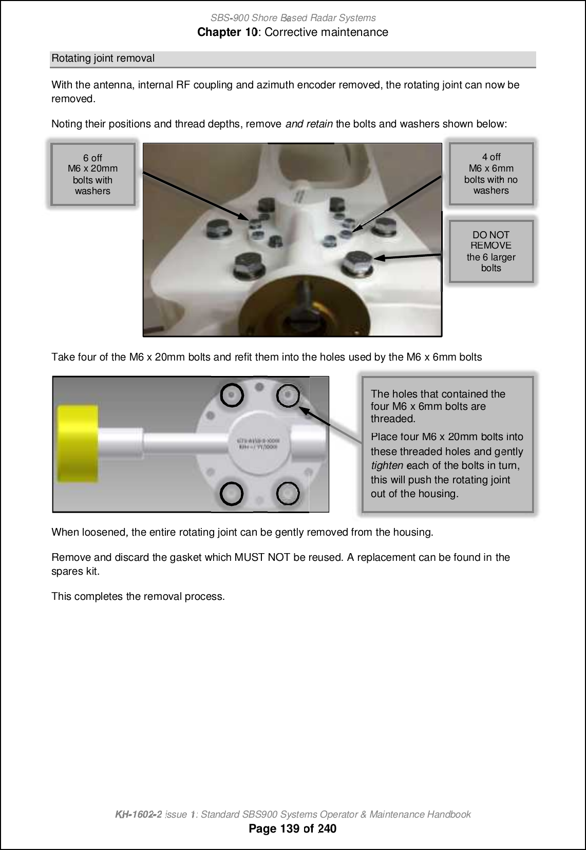
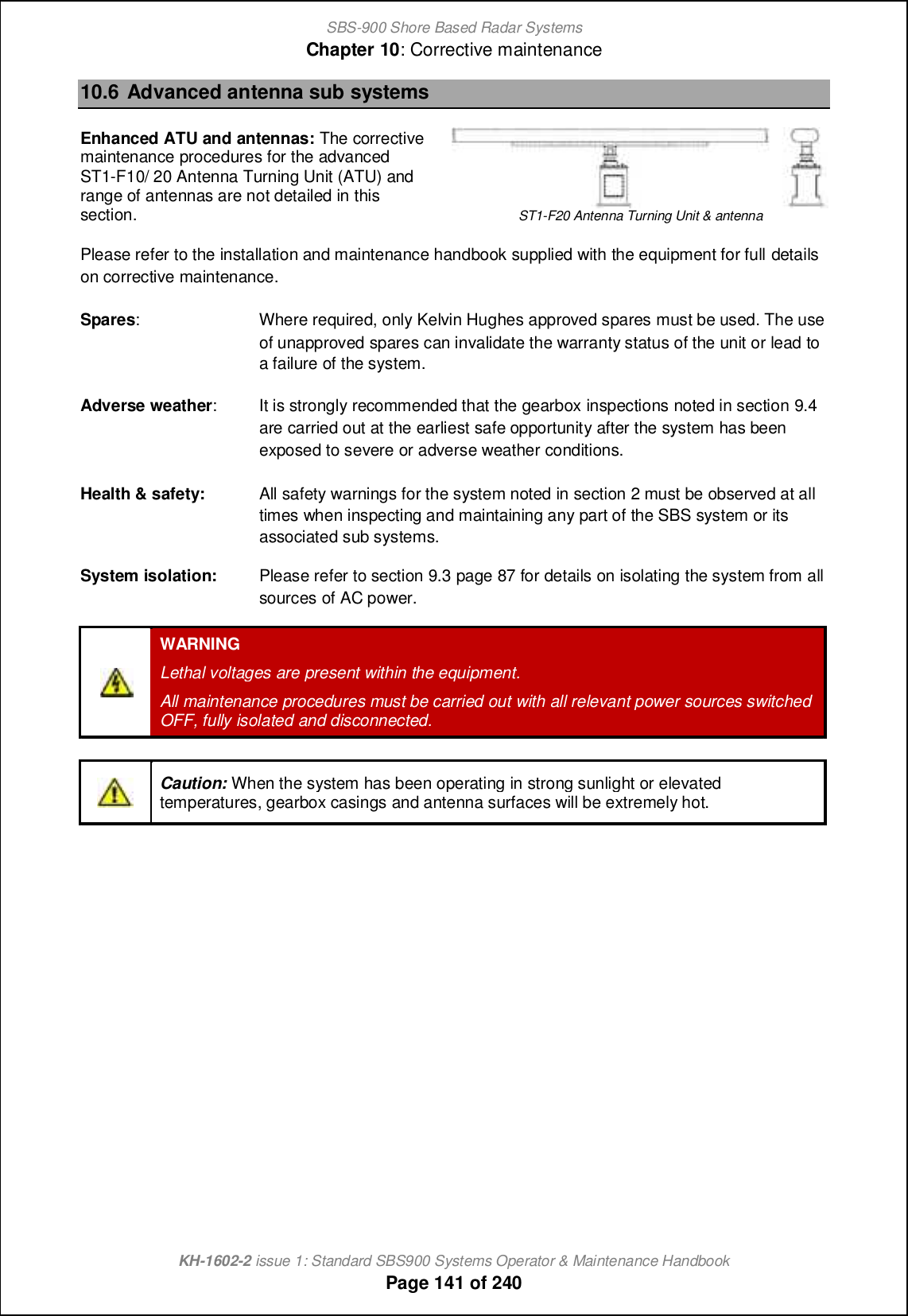
![SBS-900 Shore Based Radar SystemsChapter 10: Corrective maintenanceKH-1602-2 issue 1: Standard SBS900 Systems Operator & Maintenance HandbookPage 140 of 240ReplacementRotating joint To replace the rotating joint, reverse the above procedure using the replacementgasket+ \off_n [h^ N lcha `ioh^ ch nb_ mj[l_m ecn-RF coupling& azimuthencoder Reverse the removal process shown in section 10.5.4 pages 136 onwards.AntennaReverse the removal procedure detailed in the above section.-Dhmol_ nb_ l_jf[]_g_hn \off_n [h^ N lcha [l_ ]ill_]nfs chmn[ff_^ ch nb_ waveguide junction between the ro-jo and the antenna waveguide.To avoid SharpEyeTM SWR errors at start up, ensure that ALL connectors arecorrect and secure. Pay particular attention to the coupling bullets, Ro-Jo toFlexi Waveguide & Co-Ax Adaptor.- Tighten and torque load the 12 antenna retaining bolts to 56 Nm and applyLoctite 222 on their threads during assembly.- Waterproof the waveguide joint by sealing with a layer of greased plastic]igjioh^ mo]b [m G_hf_sm ]igjioh^ il C_hmi-Tape.- After installation, the antenna should be checked to ensure that it can freelyrotate without obstruction.](https://usermanual.wiki/Kelvin-Hughes/DTX-A3-FDLR/User-Guide-2620132-Page-140.png)
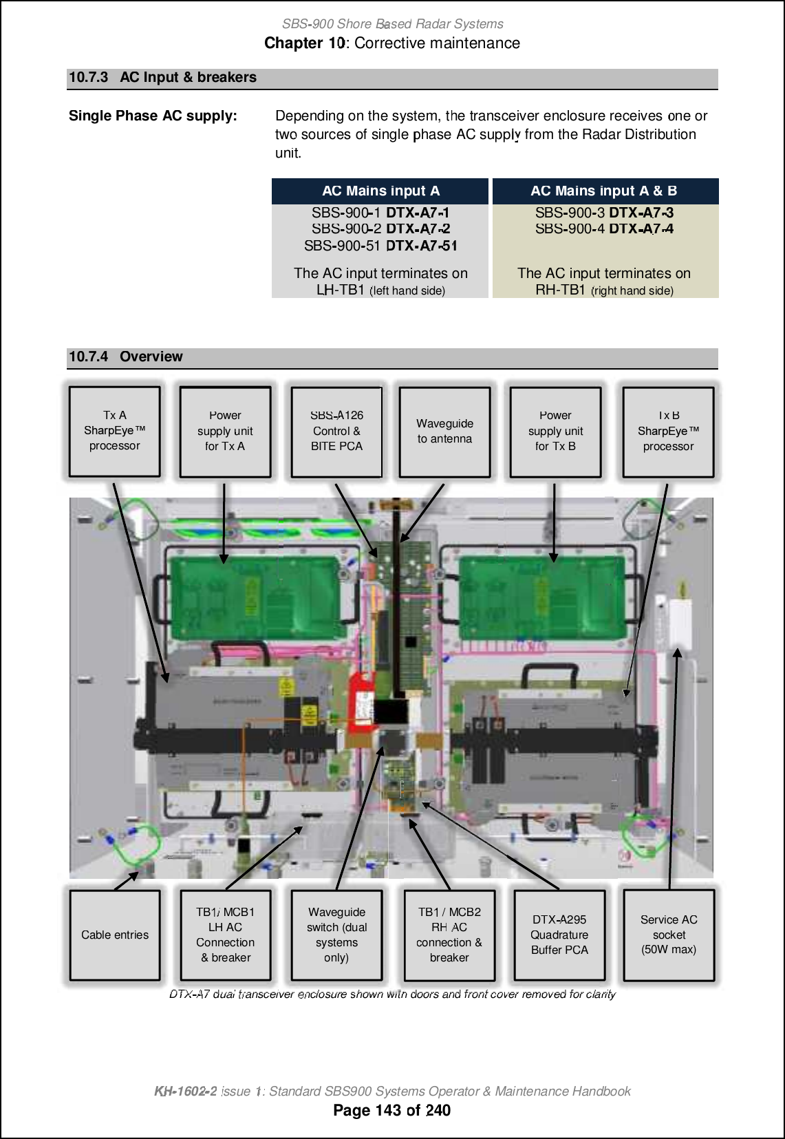

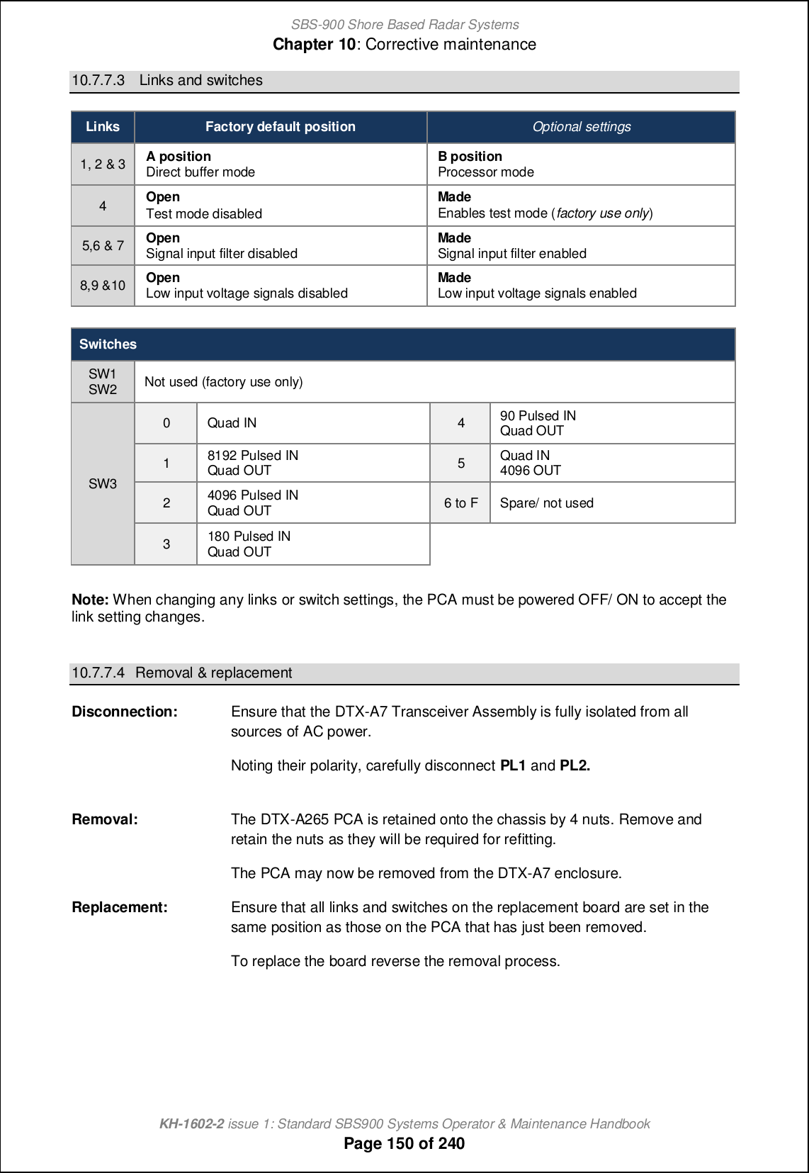

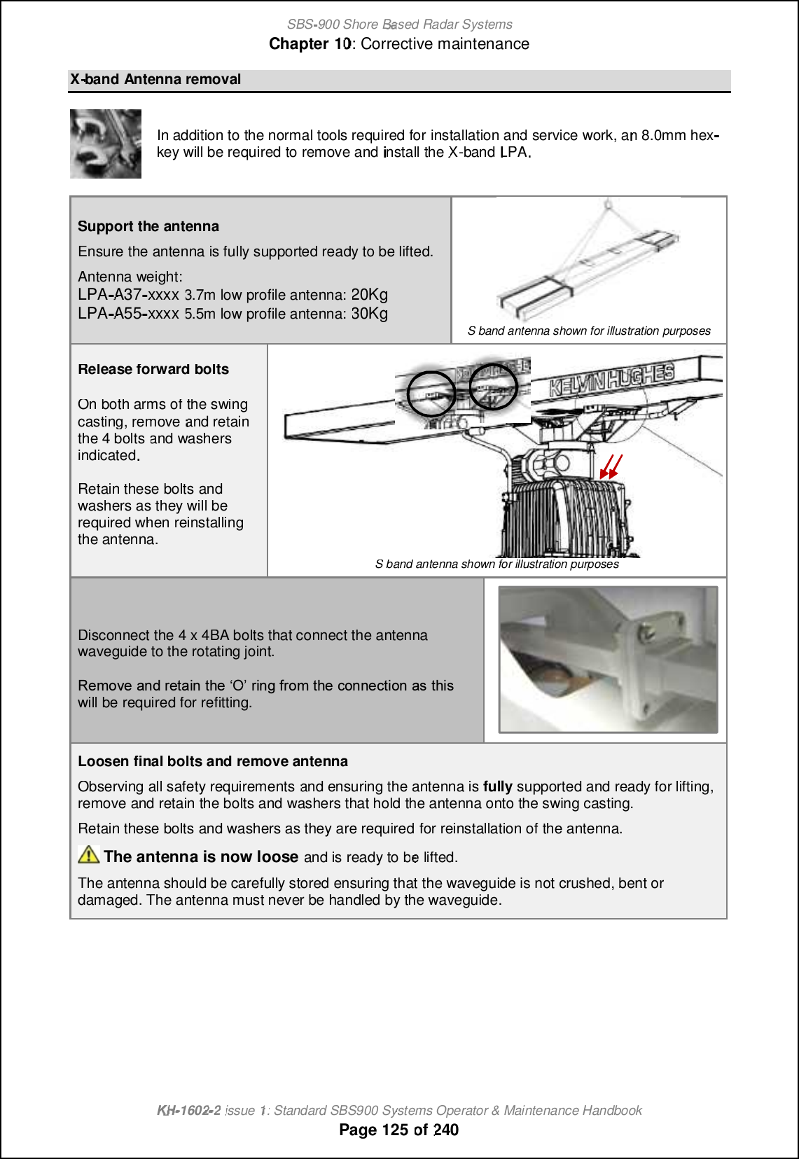
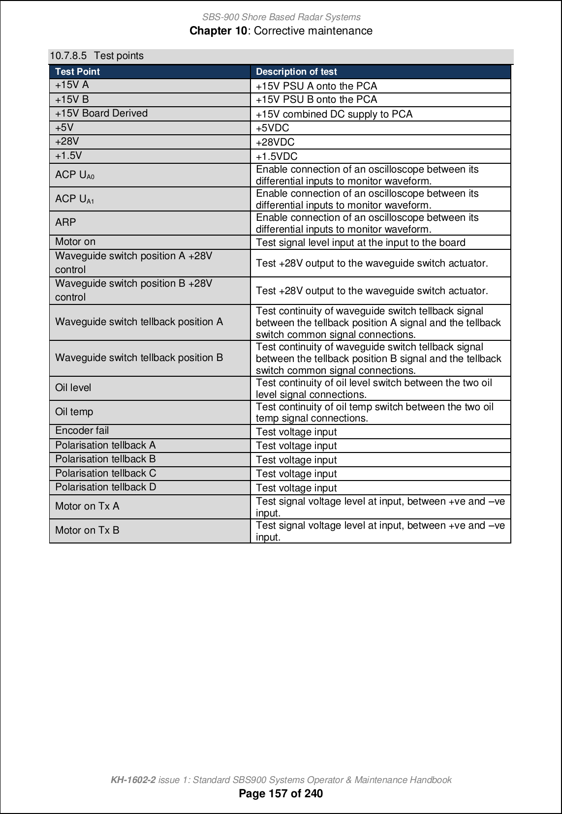
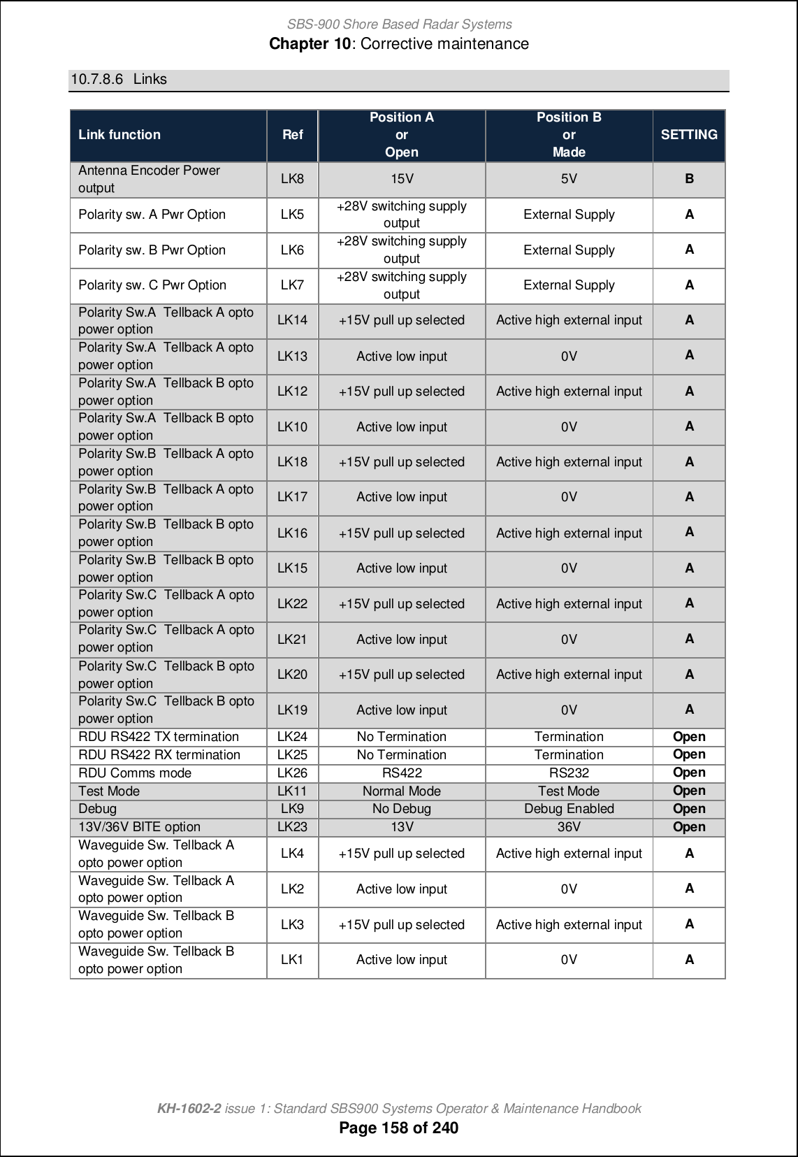
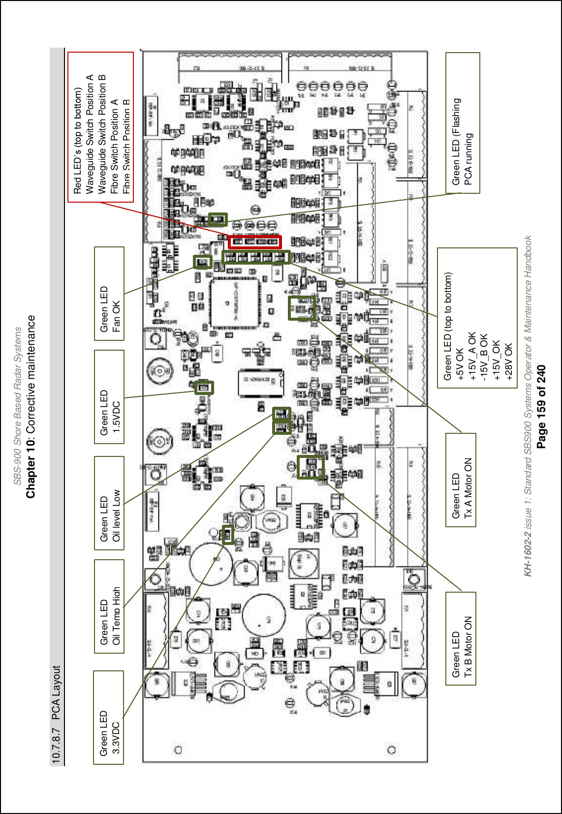
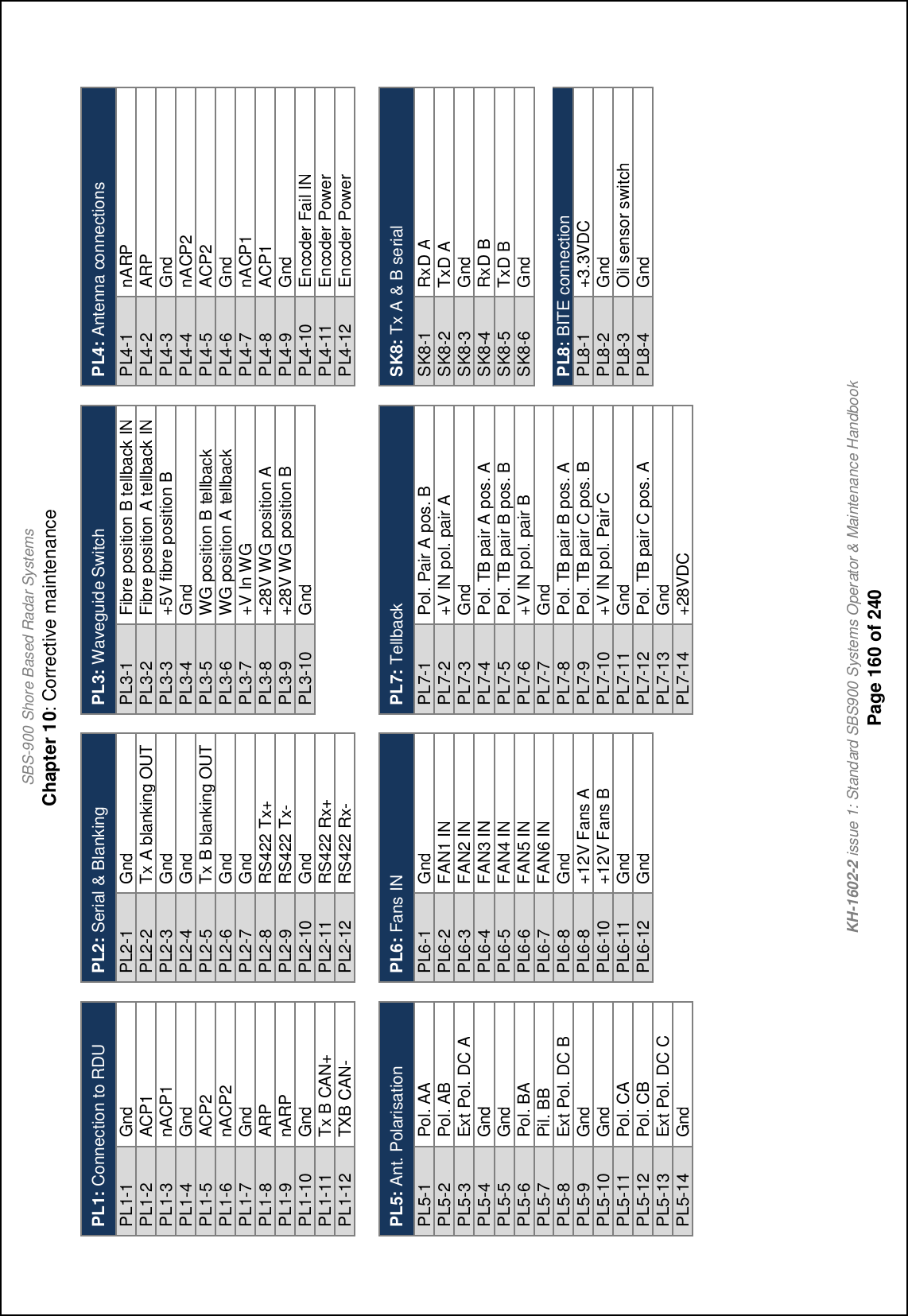
![SBS-900 Shore Based Radar SystemsChapter 10: Corrective maintenanceKH-1602-2 issue 1: Standard SBS900 Systems Operator & Maintenance HandbookPage 153 of 24010.7.8 SBS-A126 Switch Control & BITE PCA10.7.8.1 OverviewThe Switch control and BITE PCA system is a non-critical link in the system where one or twoSharpEyeTM transceivers are located within the same enclosure and share a single antenna sub-system.The role of the Switch control and BITE PCA is to:'Derive power for the +5V advanced antenna sub-system ACP/ ARP encoder.'Derive power for the +28V waveguide switch.'Provide power to the +15V Standard antenna sub-system ACP/ ARP encoder.'Monitor and digitally transmit voltage levels via RS422.'Monitor system states and transmit via RS422 to the RDU.'Monitor enclosure temperature using on-board sensor and transmit via RS422 to the RDU.'Receive commands via RS422 and activate waveguide switch and polarisation switch.'Ccmnlc\on_ Rcah[fm `lig nb_ @hn_hh[ _h]i^_l ni nb_ Rb[ljDs_x nl[hm]_cp_lm [h^ nb_ QCT-'Clcp_ nb_ \f[hecha ionjonm `lig nb_ Rb[ljDs_x nl[hm]_cp_lm ni nb_ QCT-'Allow throughput of video, sync and CAN signals to transceiver B.Tx A Tx BPSUAPSUBSwitch control and BITE PCARDUAntenna Sub-SystemSwitched Mains BFibre Control and StstusControl & StatusMotor OnBlanking BlankingMotor OnSwitched Mains ARS422 / Blanking A+BOil Level and Temp StatusDC / ACP / ARP / FailPolarization control & statusDC Power440V Motor DriveDC PowerDC Power DC PowerWaveguideWaveguideWaveguideFibre Control and StatusACP/ARPCANBUSCANBUSVideo & SyncVid & SyncOptionalCoolingFansRPM Data x6Simplified Switch control and BITE PCA interconnection diagram](https://usermanual.wiki/Kelvin-Hughes/DTX-A3-FDLR/User-Guide-2620132-Page-153.png)
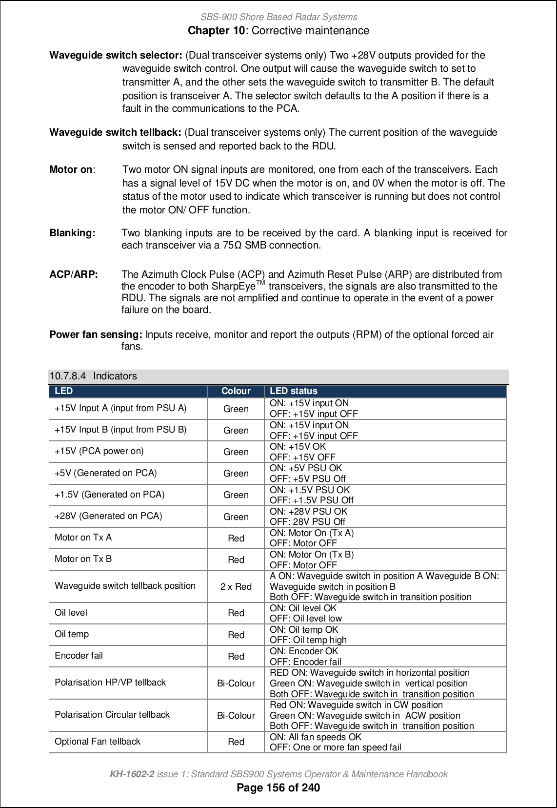
![SBS-900 Shore Based Radar SystemsChapter 10: Corrective maintenanceKH-1602-2 issue 1: Standard SBS900 Systems Operator & Maintenance HandbookPage 155 of 24010.7.8.3 Signal interfaces:There are multiple interfaces for the Switch control and BITE PCA. The status of the various inputs ismonitored and transmitted to the RDU.Control andBITE PCATx A Tx BTurning MechanismCHL or KH AntennaEncoder FailProcessorOil LevelOil TempHorizontal PolarisationWaveguide SwitchSwitch Position ASwitch Position BTellbackDriverMotor OnMotor OnRDURS422DifferentialDriverDifferentialDriverBlankingBlankingBlankingBlanking Circular PolarisationDriverPolarisation TellbackCANACPARPVideoSyncACPARPTemperatureSensorTempACPARPACPARPOptionalCoolingFansRPM Data x6SBS-A126 signal interface schematicOil level: The oil level indicator monitors a normally closed voltage free contact. An open circuitch^c][n_m [ fiq icf `[ofn ]ih^cncih- Sbcm cm ihfs [p[cf[\f_ ih advanced antenna sub-systems.Oil temp: The oil temperature indicator monitors a normally closed voltage free contact. Anij_h ]cl]ocn ch^c][n_m [h ip_l n_gj_l[nol_ `[ofn ]ih^cncih- Sbcm cm ihfs [p[cf[\f_ ih advanced antenna sub-systems.Encoder fail: The encoder on advance antenna sub-systems has a TTL (+5.0VDC) encoder failsignal. @ l_]_cp_^ mcah[f i` z2.5V indicates normal operation, a signal of <0.5Vch^c][n_m [h Dh]i^_l E[cf `[ofn ]ih^cncih-Polarisation control: This is only available on advanced antenna sub-systems and controls thestatus of the antenna polarisation. The default position is horizontal.Polarisation tellback: The current polarisation position is fed to the PCA and reported to the RDU.](https://usermanual.wiki/Kelvin-Hughes/DTX-A3-FDLR/User-Guide-2620132-Page-155.png)

![SBS-900 Shore Based Radar SystemsChapter 10: Corrective maintenanceKH-1602-2 issue 1: Standard SBS900 Systems Operator & Maintenance HandbookPage 163 of 24010.7.9 SharpEyenerror messagesIf a fault condition is detected within the SharpEyeTM transceiver, a fault message is sent to the RadarDistribution Unit and in certain conditions the unit switches to a degraded low power state ofoperation.The following is a list of possible alarm conditions that can occur within the SharpEye transceiver.SharpEyeTMerror Message DescriptionRx sensitivity If the minimum detectable signal rises above a pre-set level the transceiversends a receiver sensitivity warning message.VSWRIf the VSWR on the RF output is worse than 1.4:1 the transceiver sends anantenna VSWR warning message and switches to the degraded fiq jiq_l state of operation.If the VSWR on the RF output is worse than 2.0:1 the transceiver enters faultmode and is shutdown.SYNTH The synthesiser has not initialised correctly; cycling the power may clear thiscondition (emergency stop).Tx powerIf the RF output power falls below 100W the transceiver sends an RF PowerLOW warning message and switches to the degraded fiq jiq_l state ofoperation.Over temperatureIf the temperature of the RF power transistors in the transceiver exceeds ajl_^_n_lgch_^ fcgcn+ nb_ nl[hm]_cp_l m_h^m [h •ip_l-n_gj_l[nol_ q[lhcha ni nb_ Radar Distribution Unit and switches to the degraded fiq jiq_l state.If the temperature exceeds a further pre-set limit the transceiver switches tothe fault state and transmission is stopped.As the temperature returns to within the predetermined limits, the transceiverreturns to the degraded state and then to normal transmit operation.Turning info lostIf the antenna stops rotating when not commanded to stop, a warningmessage is sent to the display equipment and the transceiver switches to thefault state and transmission is stopped.ARP/HL notdetectedIf an azimuth or heading line pulse is not detected, a message is sent to thetransceiver and for safety reasons transmission is stopped within 60 seconds.Azimuth status(1)Antenna rotation is checked for clockwise rotation (viewed from above). If anti-clockwise rotation is detected, a message is sent and transmission is stoppedwithin 60 seconds.Azimuth status(2)If missing pulses between heading lines are detected, a message is sent andtransmission is stopped within 60 seconds.](https://usermanual.wiki/Kelvin-Hughes/DTX-A3-FDLR/User-Guide-2620132-Page-163.png)

![SBS-900 Shore Based Radar SystemsChapter 10: Corrective maintenanceKH-1602-2 issue 1: Standard SBS900 Systems Operator & Maintenance HandbookPage 165 of 24010.7.10 X-band transceiver processor10.7.10.1 OverviewSb_ mifc^ mn[n_ Rb[ljDs_x nl[hm]_cp_l(s) are secured inside the transceiver enclosure and arecontrolled by the Radar Distribution Unit.SharpEye processor gsealed unit:'The SharpEyeTM processor uses solid state components and has no 'lifed' items.'The unit has no field serviceable or repairable parts and must be returned to themanufacturer for repair.'The processor must never be dismantled as it is a sealed unit that contains beryllium(see health and safety notices in section 2).Spares kits: Where a SharpEyeTMprocessor is supplied as a spare, it is shipped ina kit form that includes:- A spare processor- A ruggedised delivery case that must be used for returning the removedprocessor-Instructionson returning the removed unitPrecautionsHEAVY ITEM: The SharpEyeTM transceiver is a heavy item. Care should be exercisedwhen removing and moving the processor.HOT SURFACES: If the SharpEyeTM has been in operation or the transceiver enclosurehas been exposed to strong sunlight, the processor unit will be hot to the touch.Do not operate the SharpEyeTM system with the waveguide or antenna disconnected.No. of people: Due to the weight of the processor and depending on the level of access tothe transceiver Enclosure, it is recommended that changing the processor iscarried out by two people.Health & Safety: All health and safety notices shown in section 2 must be observed at all timesincluding those regarding working aloft.ToolsTools: In addition to the normal tools required for service work, the following tools will berequired to carry out this replacement.- 4BA open ended spanner- 5.0mm Allen key (recommended 150mm long)](https://usermanual.wiki/Kelvin-Hughes/DTX-A3-FDLR/User-Guide-2620132-Page-165.png)
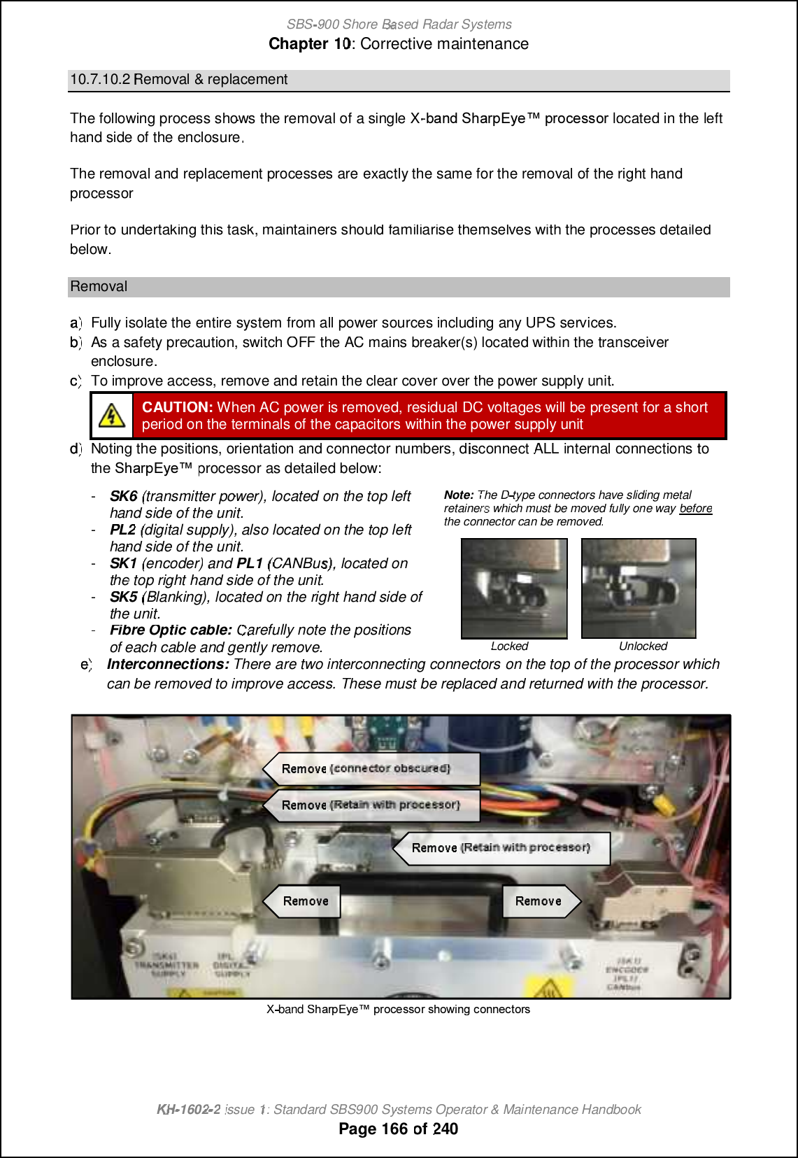
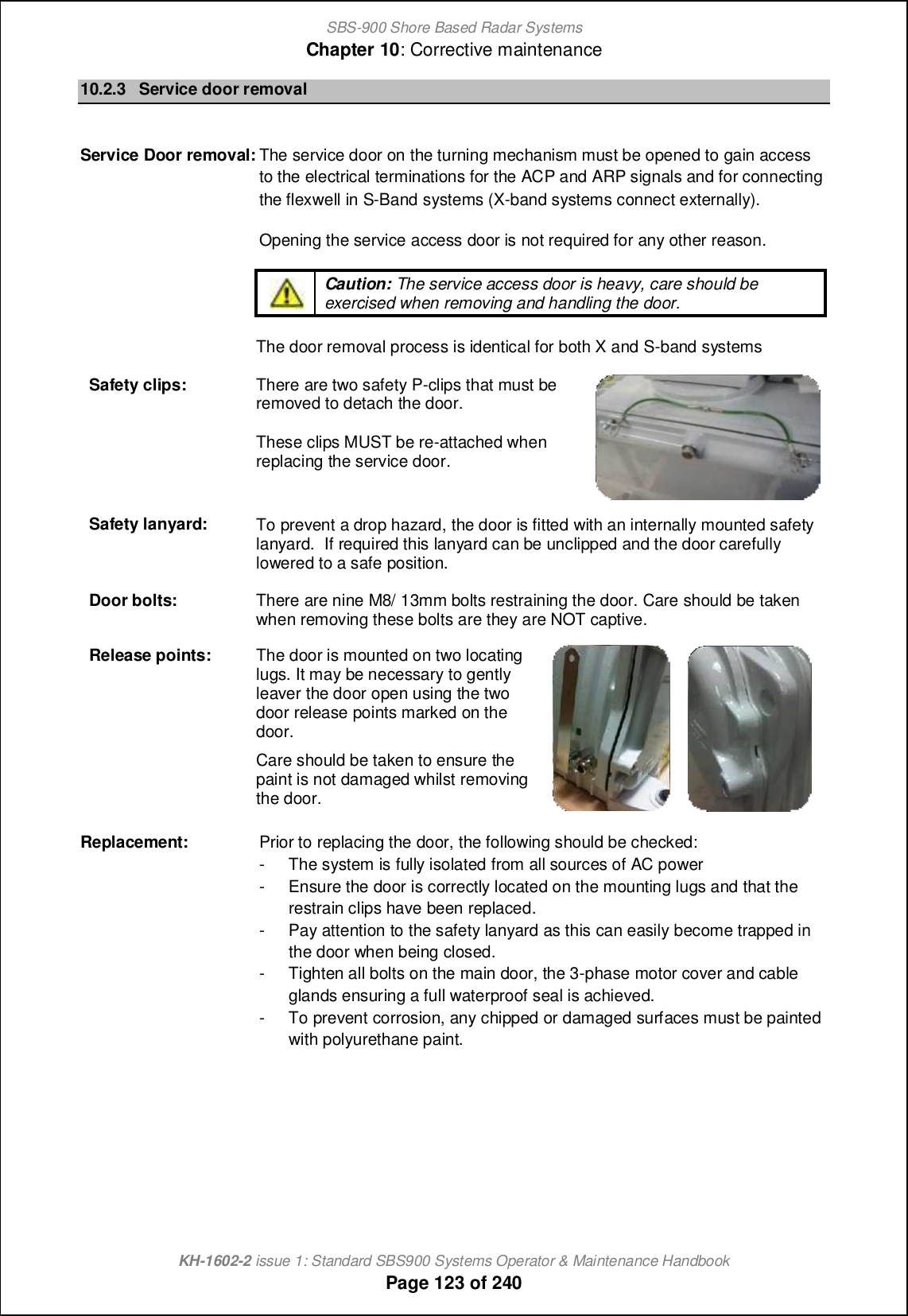
![SBS-900 Shore Based Radar SystemsChapter 10: Corrective maintenanceKH-1602-2 issue 1: Standard SBS900 Systems Operator & Maintenance HandbookPage 168 of 240g) Processor removal: The SharpEyeTM processor is retained into the Enclosure by 17 x 5mm hexbolts. These should be removed, retained and the processor carefully lifted from the assemblyusing the carrying handles.Caution: Sb_ \ifnm ih nb_ Rb[ljDs_x jli]_mmil cnm_f` LTRS MNS AD QDLNUDC;removal of these bolts invalidates the warranty status of the unit (see below).Bolts to be removed DO NOT removeNote: Some of the bolts circled below are obscured in the drawing.X-=TaW L[Tec@lXo JebVXffbeRemoval hint: Rotating the processor by 90 degrees makes it easier to remove the unit fromthe processor.](https://usermanual.wiki/Kelvin-Hughes/DTX-A3-FDLR/User-Guide-2620132-Page-168.png)
![SBS-900 Shore Based Radar SystemsChapter 10: Corrective maintenanceKH-1602-2 issue 1: Standard SBS900 Systems Operator & Maintenance HandbookPage 169 of 240Processor replacementReplacement: The processor is replaced by reversing the removal procedure.Supporting lugs: The processor can be temporarily rested on two logs inserted into thebackplate of the enclosure. This helps to support and align the processorduring the replacement processes but does not secure the unit into place.Caution: As noted in the previous section, the processor is a heavy item;care should be exercised when replacing the unit.Retaining bolts: Replace the 17 retaining bolts and washers removed earlier in the removalprocess. ALL 17 fasteners MUST be replaced.Caution: The bolts ensure that a full thermal bond is achieved between theprocessor and the heatsink in the enclosure. Failure to replace a boltincreases the possibility of a poor bond leading to L[Tec@lXo cebVXffbeoverheating issues.Waveguide: Replace the waveguide joiner removed earlier betweennb_ Rb[ljDs_x jli]_mmil [h^ nb_ g[ch q[p_aoc^_- @ffnuts, bolts, washers and waveguide shims/ O-ringsmust be replaced.Pay particular attention to the orientation of thewaveguide shim.Connectors: Reconnect all connectors.The D-type connectors have sliding metal retainers which must be movedfully one way to lock the connector into positionLocked UnlockedRe-Y\go7 Where removed to improve access, refit the following:- The fibre Optic cable/ connector- Static desiccator- Clear power supply protection cover.Unit inspection: Prior to restoring AC power to the system carry out the following checks:- All fasteners are securely tightened.- All connectors are securely fitted in the correct positions.- All RF (Waveguide) couplings are securely and correctly fitted andtightened.Test: When th_ Rb[ljDs_x jli]_mmil b[m \__h mo]]_mm`offs l_-fitted, apply ACpower to the system and test.](https://usermanual.wiki/Kelvin-Hughes/DTX-A3-FDLR/User-Guide-2620132-Page-169.png)
![SBS-900 Shore Based Radar SystemsChapter 10: Corrective maintenanceKH-1602-2 issue 1: Standard SBS900 Systems Operator & Maintenance HandbookPage 171 of 24010.7.11 S-band Transceiver processor10.7.11.1 OverviewSb_ mifc^ mn[n_ Rb[ljDs_x nl[hm]_cp_l is secured into the right hand side of the transceiverenclosure and is controlled by the Radar Distribution Unit.SharpEye processor gsealed unit:'The SharpEyeTM processor uses solid state components and has no 'lifed' items.'The unit has no field serviceable or repairable parts and must be returned to themanufacturer for repair.'The processor must never be dismantled as it is a sealed unit that contains beryllium(see health and safety notices in section 2).Spares kits: Where a SharpEyeTMprocessor is supplied as a spare, it is shipped ina kit form that includes:- A spare processor- Full removal and installation instructions- A ruggedised delivery case that must be used for returning the removedprocessorPrecautionsHEAVY ITEM: The SharpEyeTM transceiver weighs approximately 15Kg. Care should beexercised when removing and moving the processor.HOT SURFACES: If the SharpEyeTM has been in operation or the transceiver enclosurehas been exposed to strong sunlight, the processor unit will be hot to the touch.Do not operate the SharpEyeTM system with the waveguide or antenna disconnected.No. of people: Due to the weight of the processor and depending on the level of access tothe transceiver Enclosure, it is recommended that changing the processor iscarried out by two people.Health & Safety: All health and safety notices shown in section 2 must be observed at all timesincluding those regarding working aloft.ToolsTools: In addition to the normal tools required for service work, the following tools will berequired to carry out this replacement.- 4BA open ended spanner- 5.0mm Allen key (recommended 150mm long)](https://usermanual.wiki/Kelvin-Hughes/DTX-A3-FDLR/User-Guide-2620132-Page-171.png)
![SBS-900 Shore Based Radar SystemsChapter 10: Corrective maintenanceKH-1602-2 issue 1: Standard SBS900 Systems Operator & Maintenance HandbookPage 172 of 24010.7.11.2 S band processor removal & replacementThe following process shows the removal of a single S-\[h^ Rb[ljDs_x processor located in theright hand side of the enclosure.Prior to undertaking this task, maintainers should familiarise themselves with the processes detailedbelow.RemovalThe removal process is identical to the X-band processor removal shown in the previoussection. Please refer this section for instructions.RF coupling: The only difference between the X-band and S-band removal is the RF coupling. Inthe S-band system the waveguide is replaced by a semi-rigid RF coupling.ReplacementReplacing the S-band SharpEye processor is carried out using the replacement processes describedin the X-band section.The only difference between the X-band and S-band removal is the RF coupling. In the S-bandsystem the waveguide is replaced by a semi-rigid RF coupling.Refitting the semi-rigid RF cable: When refitting the cable, ensure you observe the handlingprecautions noted below.- The nut on the semi-rigid RF cable should be tightened to 1.0Nm.-H` hi nilko_ ql_h]b cm [p[cf[\f_ nb_ `[mn_hcham mbiof^ \_ a_hnfs ncabn_h ni •finger tight-- DO NOT over tighten as this can deform and damage the cable.Semi-rigid coaxial cable handling precautions:- Take care when removing and re-installing the coaxial cable.- The rigid coaxial cable must not be bent, crushed, deformed or damaged in any way.- If the cable is accidently damaged, it must be replaced.-Damage to this cable can reduce the transceiver performance or in the worst case stoptransmission.Semi-rigid coaxial cable handling precautions:- Take care when removing and re-installing the coaxial cable.- The rigid coaxial cable must not be bent, crushed, deformed or damaged in any way.- If the cable is accidently damaged, it must be replaced.-Damage to this cable can reduce the transceiver performance or in the worst case stoptransmission.](https://usermanual.wiki/Kelvin-Hughes/DTX-A3-FDLR/User-Guide-2620132-Page-172.png)

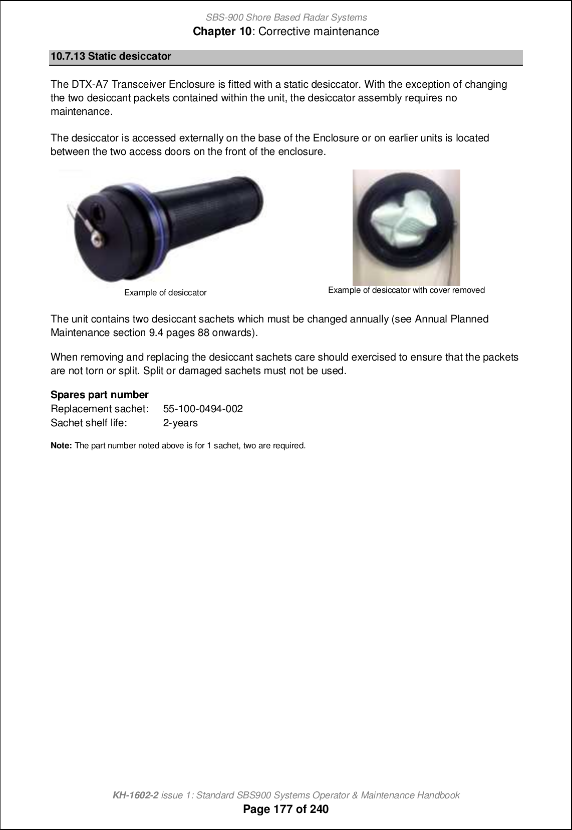
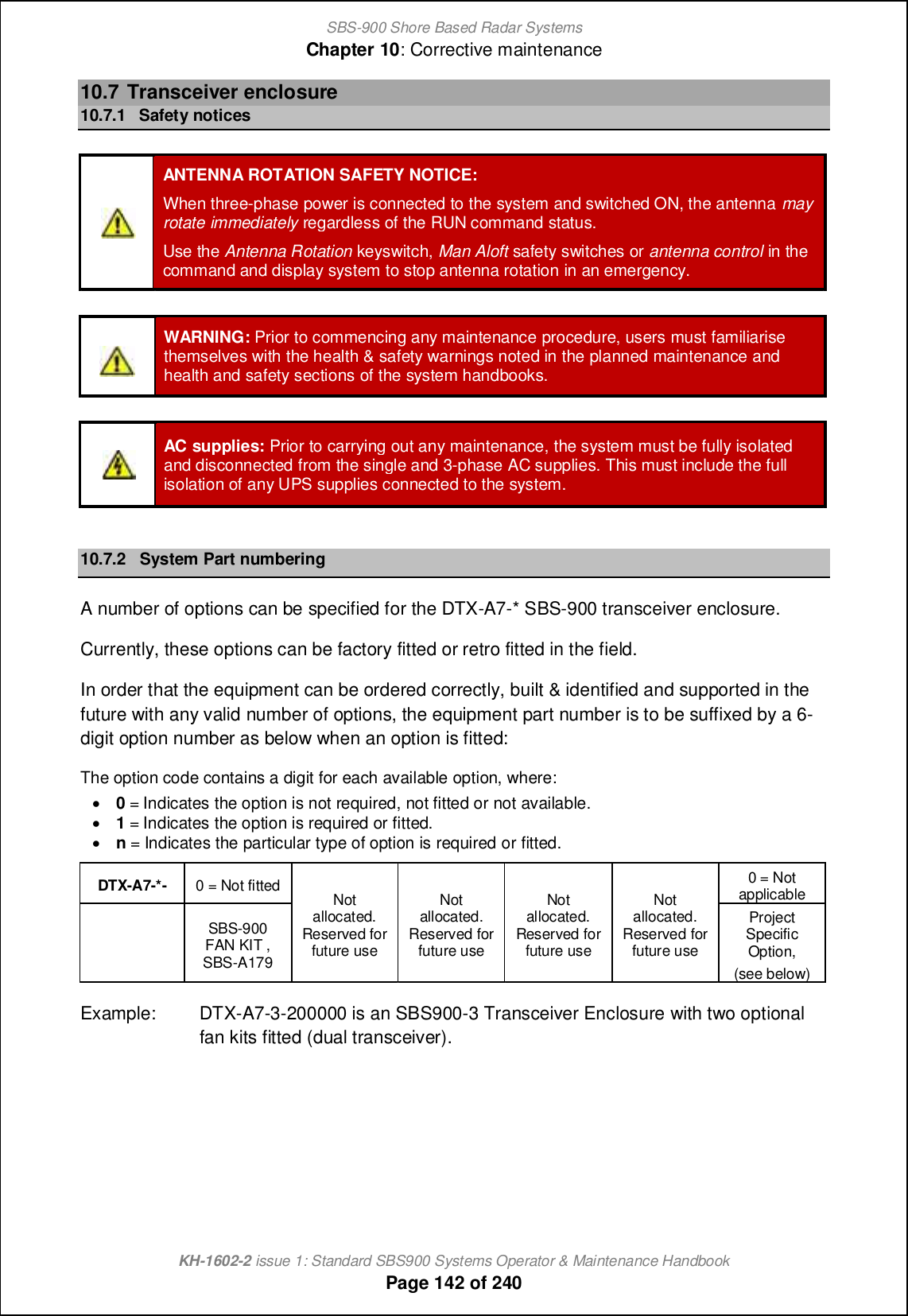
![SBS-900 Shore Based Radar SystemsChapter 10: Corrective maintenanceKH-1602-2 issue 1: Standard SBS900 Systems Operator & Maintenance HandbookPage 178 of 24010.7.14 Service socketAC socket: A universal switched AC service socket is provided withinthe transceiver enclosure and is located on the right handside of the unit.Maximum load: The maximum load on this AC output is 100W10.7.15 IlluminationWhen the AC breaker is switched ON, LED illumination is provided within the Transceiver enclosure.There is no switch for the lighting which remains illuminated at all times when AC power is presentand switched ON.10.7.16 Spares listingDescription Part numbers(s)Rb[ljDs_x nl[hm]_cp_l [mm_g\fs Note 1 Please contact Kelvin Hughes Ltd for details.Control and BITE PCA SBS-A126Power Converter module Assembly (PSU) SBS-A146AC line filter 45-690-0077-001AC Mains relay (12VDC 16A) 85-200-0059-001LED (for AC breaker) 45-6000-0118-001MCB 10A DIN rail mounting 45-600-0102-001Quadrature puffer PCA DTX-A295Wind turned rotary ventilator 45-925-0032-001 (1 per)Static Desiccator sachets 55-100-0494-002LED strip light (1 per) 45-625-0032-001Note 1: The SharpEye processor will be shipped as a spares replacement kit containing the main processor and aruggedised transport/ returns case.](https://usermanual.wiki/Kelvin-Hughes/DTX-A3-FDLR/User-Guide-2620132-Page-178.png)


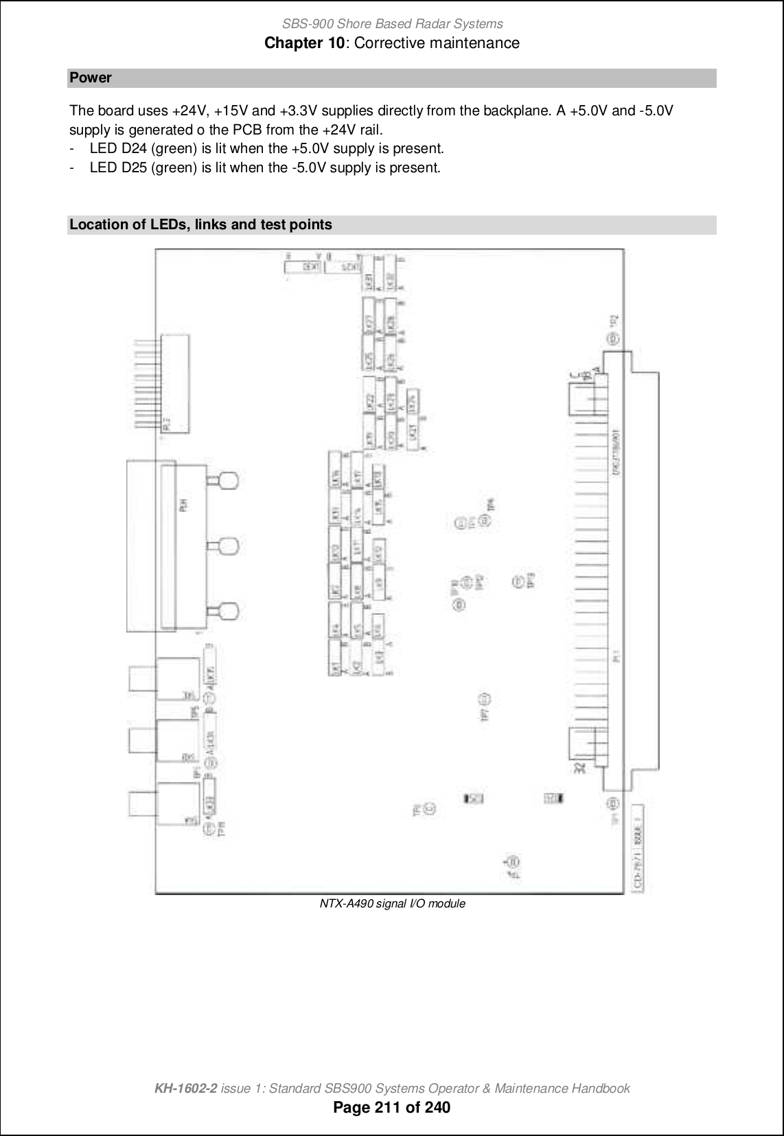

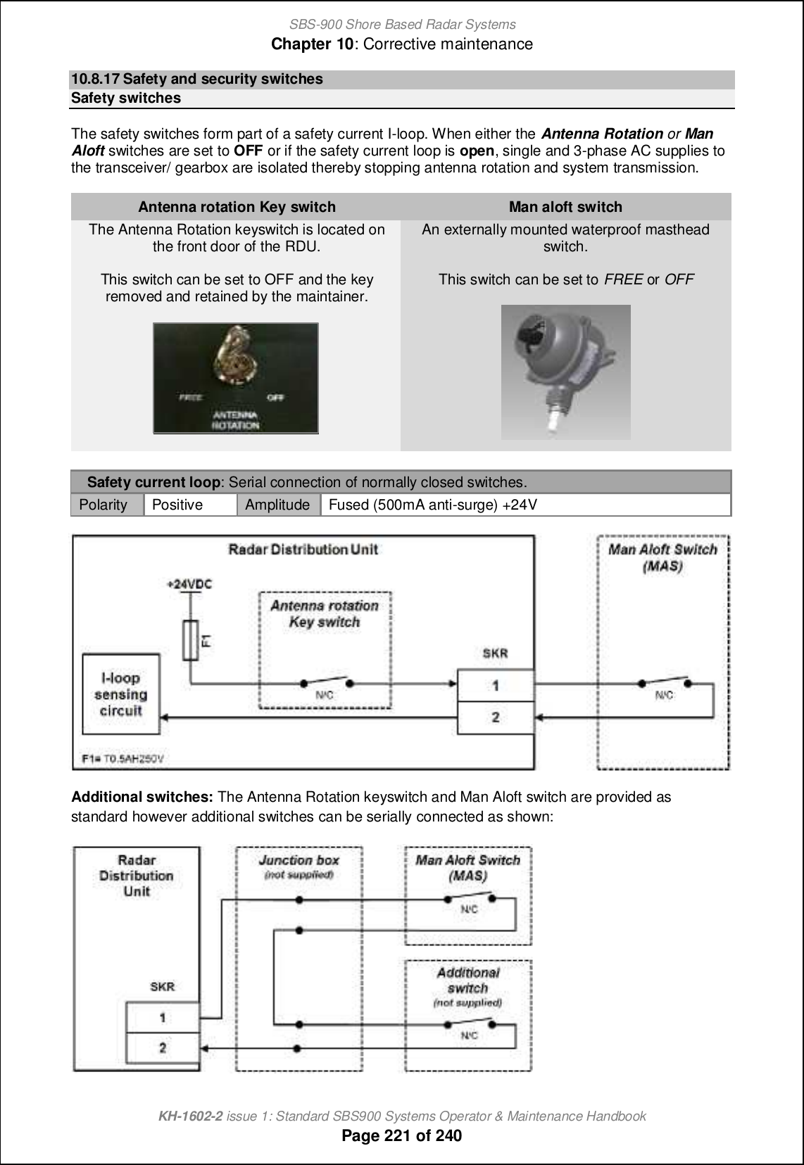
![SBS-900 Shore Based Radar SystemsChapter 10: Corrective maintenanceKH-1602-2 issue 1: Standard SBS900 Systems Operator & Maintenance HandbookPage 222 of 240Security switchesConnections are provided on the RDU for two security switches. The system reports the status ofthese switches to the command and display system, track extractor or optional service display.The normally closed (N/C) switch inputs switches are for monitoring purposes only and do not isolateor control any aspect of the system.Where fitted, these switches must be enabled during setting to work of the system.Two switch connections are available as follows:SKM / Ant Platform: This is designed for a security switch on the gate or access point to theantenna platform.SKN / Hut door: This is designed for a security switch on the equipment building or hut accessdoor.Additional security switches can be serially added using a junction box (not supplied) in a similarfashion to the security switches as shown on the previous page.Antenna platform/ Hut door switch: Normally closed (N/C) switch returning a voltage back toRDU.Polarity Positive Amplitude *04U qcnb m_lc_m 2e2 ]oll_hn fcgcncha l_mcmnil](https://usermanual.wiki/Kelvin-Hughes/DTX-A3-FDLR/User-Guide-2620132-Page-222.png)
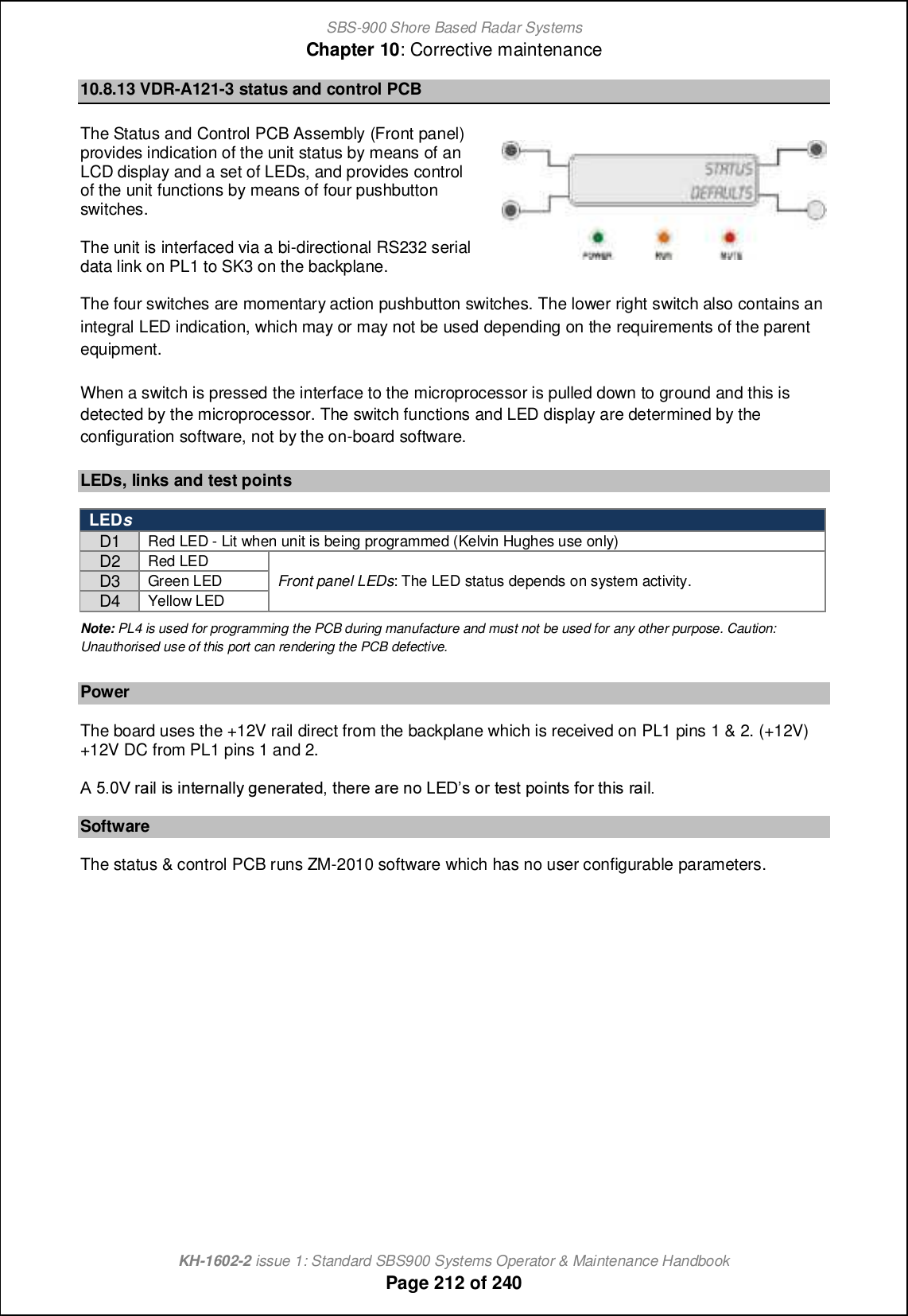
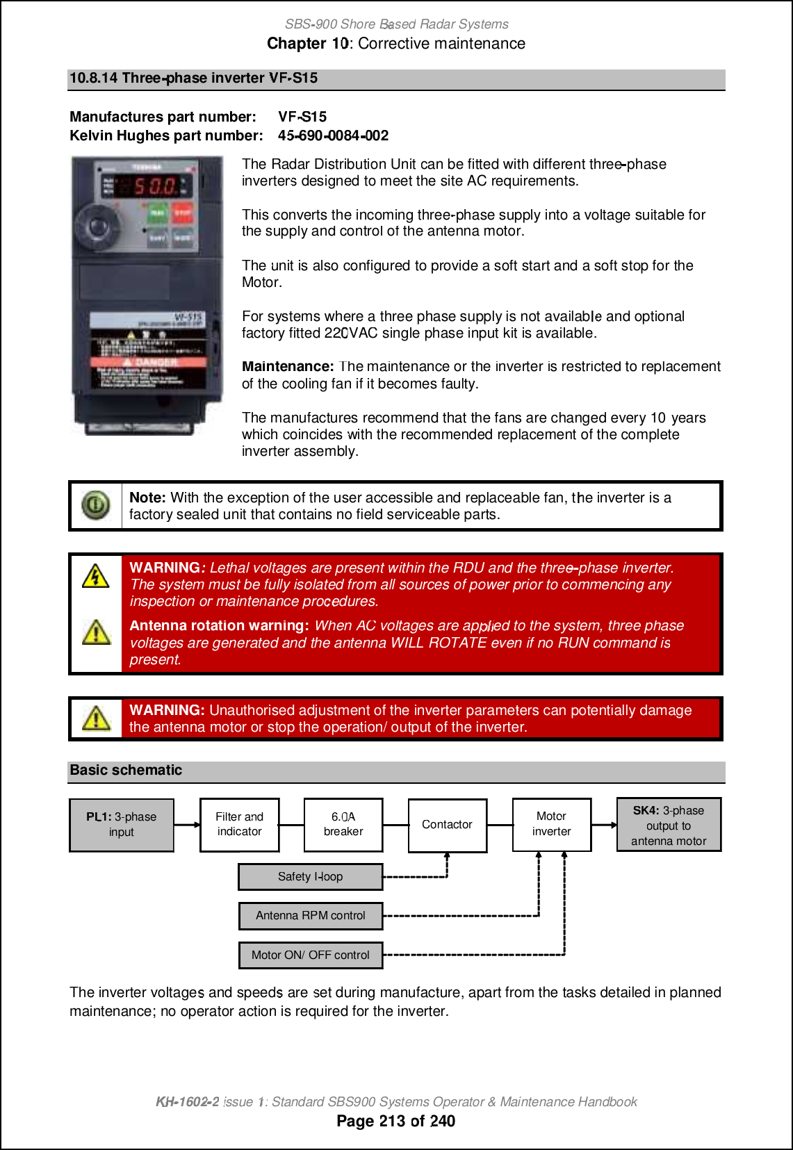
![SBS-900 Shore Based Radar SystemsChapter 10: Corrective maintenanceKH-1602-2 issue 1: Standard SBS900 Systems Operator & Maintenance HandbookPage 225 of 240RDU LCDMessage System status DescriptionOil leveltemperatureInformation warning only; no changein system performance.The oil temperature in the CHL gearbox is high. Atthe earliest safe opportunity, a general inspectionof the antenna should be made to see if there isany reason for the elevated oil temperature.The oil level should also be checked.Overtemperature 1Message received fromSharpEyeTM processor.Transceiver switches to Low powermode. See note belowIf the temperature of the RF power transistors inthe transceiver exceeds predetermined limits, thenl[hm]_cp_l m_h^m [h •ip_l-n_gj_l[nol_ q[lhcha ni the Radar Distribution Unit and switches to the^_al[^_^ fiq jiq_l mn[n_- Overtemperature 2Message received fromSharpEyeTM processor. Antennarotation and system transmissionwill stop. See note belowIf the temperature exceeds a further pre-set limitthe transceiver switches to the fault state andtransmission is stopped.Over temperature notes: As the SharpEyeTM processor temperature returns to predetermined limits, the transceiverreturns to the degraded state and then to normal operation.PSUA PWRalarmDepending on the fault condition thesystem may operate normally orantenna rotation and systemtransmission may have stopped. Seenote belowIndicates a fault condition with one half of the dualredundant power supply within the RDU or aproblem with AC input A (PL2).If the fault is with the power supply, the system willoperator normally using PSUB outputs.If AC input A has failed or is lost, power to thetransceiver will also be lost stopping antennarotation and system transmission.PSUB PWRalarmInformation warning only; no changein system performance. See note belowThere is a fault with PSUB on the dual redundantpower supply within the RDU or a problem with theAC input B (PL3).The system will operator normally using PSUAoutputs.PSU A or B PWR alarm notes: The cause of any power supply related alarms must be investigated at the earliest safeopportunity and corrective action taken.Safety currentI-loop openAntenna rotation and systemtransmission will have stopped.The Safety current I loop is open.Check that the Antenna Rotation, Man Aloft Switchor any additional safety switches are in the FREE/normally closed position.Rx sensitivityThe system will be operationalhowever target detection may bereduced.If the minimum detectable signal rises above a pre-set level the transceiver sends a receiver sensitivitywarning message.Standby Antenna rotation and systemtransmission will have stopped.The system is in standby mode, ensure that nofault conditions exist that could be preventing thesystem entering Run mode.SYNTHMessage received from SharpEyeTMprocessor.Antenna rotation and systemtransmission will have stopped.The SharpEyeTM processor synthesiser has notinitialised correctly. Cycling the power to thetransceiver may clear this condition.](https://usermanual.wiki/Kelvin-Hughes/DTX-A3-FDLR/User-Guide-2620132-Page-225.png)
![SBS-900 Shore Based Radar SystemsChapter 10: Corrective maintenanceKH-1602-2 issue 1: Standard SBS900 Systems Operator & Maintenance HandbookPage 226 of 240RDU LCDMessage System status DescriptionTx powerMessage received from SharpEyeTMprocessor.The transceiver will switch to Lowpower mode (see below).If the RF output power falls below 100W thetransceiver sends an RF Power LOW warningg_mm[a_ [h^ mqcn]b_m ni nb_ ^_al[^_^ fiq jiq_l state of operation.Turning info lostMessage received from SharpEyeTMprocessor.Antenna rotation and systemtransmission will have stopped.If the antenna stops rotating when not commandedto stop, a warning message is sent to the displayequipment and the transceiver switches to the faultstate (see below) and transmission is stopped.VSWRMessage received fromSharpEyeTM processor.The transceiver will switch to LowPower or Fault mode.If the VSWR on the RF output is worse than 1.4:1the transceiver sends an antenna VSWR warningg_mm[a_ [h^ mqcn]b_m ni nb_ ^_al[^_^ fiq jiq_l state of operation (see below).If the VSWR on the RF output is worse than 2.0:1the transceiver enters fault mode (see below) andis shutdown.This can be an indication of a problem with theSharpEyeTM processor, the connecting waveguideor the antenna.SharpEyeTM modesIn some of the alarm conditions noted above, the SharpEyeTM transceiver may enter one of the threefollowing states.If any of these states is detected attempt a system reset. Should the fault condition persist pleasecontact Kelvin Hughes for further assistance.Transceiver lowpower modeThe transceiver continuously runs background performance checks on forward power,reverse power, receiver sensitivity and temperature. If any of these parameters fallsoutside predetermined levels a warning message is sent to the Radar Distribution Unitindicating the nature of the fault.The transceiver continues to operate, but with reduced performance and functionality.Caution:As a result of reduced output power, range performance will be reduced andthe system may not meet the expected operational detection performance.Transceiver faultmodeIf the performance or functionality is degraded such that the transceiver cannot operateit enters the fault state and a fault message is sent to the display equipment.The transceiver stops radiating RF and there is no video output to the RadarDistribution Unit.A spurious fault may be cleared by re-powering the equipment.RDU to transceivercommunicationerrorIf communication is lost between the Radar Distribution Unit and the SharpEyeTM, theRDU reboots the SharpEye leading to a potential 60 second gap in coverage.](https://usermanual.wiki/Kelvin-Hughes/DTX-A3-FDLR/User-Guide-2620132-Page-226.png)

![SBS-900 Shore Based Radar SystemsChapter 11: AbreviationsKH-1602-2 issue 1: Standard SBS900 Systems Operator & Maintenance HandbookPage 228 of 24011 AbreviationsAC Alternating CurrentACH Anti-condensation heaterACPAzimuth Clock PulseAISAutomatic Identification SystemARPAzimuth Reset PulseBIT /BITE Built In Test / Built in Test EquipmentCANBusController Area Network BusCFARConstant false Alarm RateCW Continuous WaveDC Direct CurrentECDIS Electronic Chart Display & Information SystemEDPCEnhanced Digital Pulse CompressionEMElectromagneticEMC Electromagnetic CompatibilityEMCON Electromagnetic ControlESMElectronic Surveillance MeasureFATFactory AcceptanceTestFCSFire Control SystemFD Frequency DiversityFSM Functional Status MessageGaNGallium NitrideGPSGlobal Positioning SystemHL Heading LineHRDPC High Resolution Digital PulseCompressionIALA International Association of LighthouseAuthoritiesIBSIntegrated Bridge SystemIEC International Electrotechnical CommitteeIF Intermediate FrequencyILSIntegrated Logistic SupportIMOInternational Maritime OrganisationI/O Input/ OutputIP Internet ProtocolIRSInterface Requirement SpecificationKHKelvin HughesKSDKelvin (Hughes) Software DocumentLAN Local Area NetworkLCD Liquid Crystal DisplayLEDLight Emitting DiodeLNFELow Noise Front EndLPA Low Profile AntennaLRU Line Replaceable UnitmMetreMACMedia Access ControlMASMan Aloft SwitchMDP L[hn[Ccacn[fx Oli]_mmilMDS Minimum Detectable SignalMISMModular Interface System ModuleMMIMan Machine InterfaceMTD Moving target DetectionMTTR Mean Time To RepairnmNautical MilePCPersonal ComputerPCBPrinted Circuit BoardPRF Pulse Repetition FrequencyPWM Pulse Width ModulationRALGerman Colour StandardRACONRadar BeaconRDURadar Distribution UnitRF Radio FrequencyRPM Revolutions Per MinuteRxReceiveSARTSearch And Rescue TransponderSBSShore Based SystemsSETD Systems Engineering Technical DocumentSTC Sensitivity Time ControlTBATo Be AdvisedTBCTo Be ConfirmedTCPTransmission ControlProtocolTFT Thin Film TransistornTrademarkTxTransmitUG_cabn ohcn i` 08 l[]e msmn_g UDPUniversal Datagram ProtocolUPS Uninterruptable power supplyUSB Universal Serial BusVSWRVoltage Standing Wave RatioWANWide Area NetworkWI Work Instruction](https://usermanual.wiki/Kelvin-Hughes/DTX-A3-FDLR/User-Guide-2620132-Page-228.png)