Kingfisher KFSTARLB0001 Radio Fire Alarm Panel User Manual

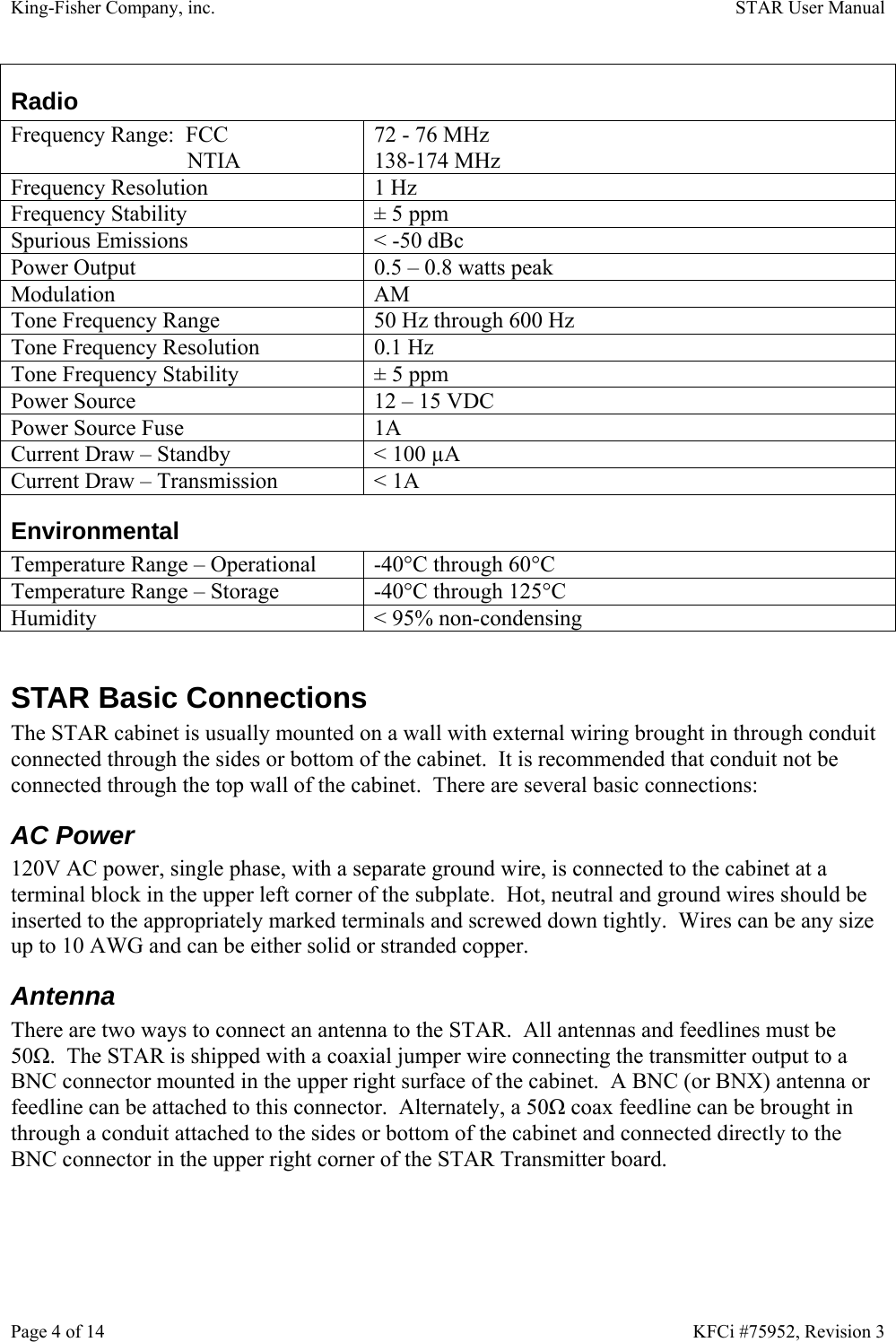
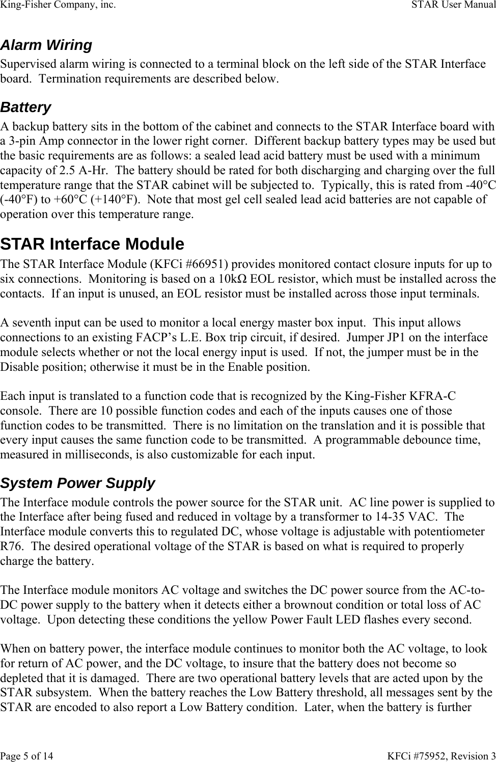
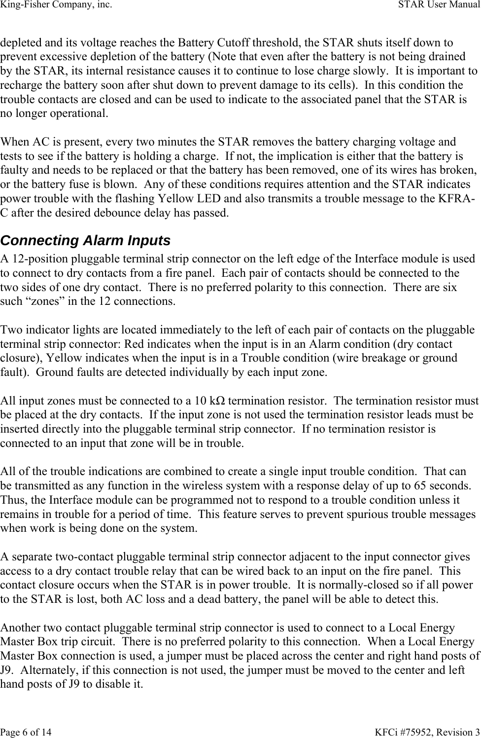
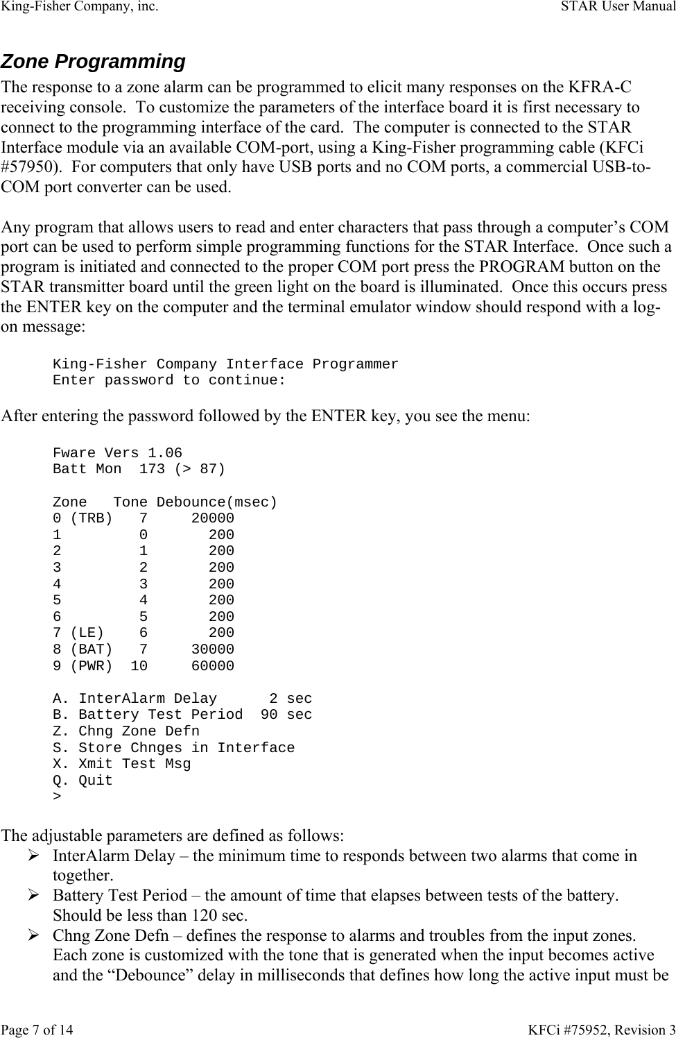
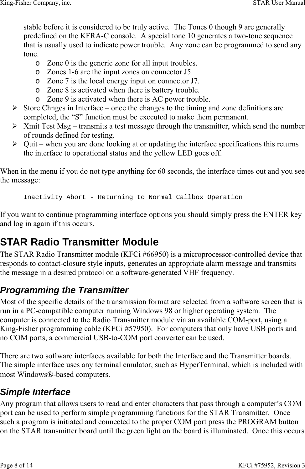
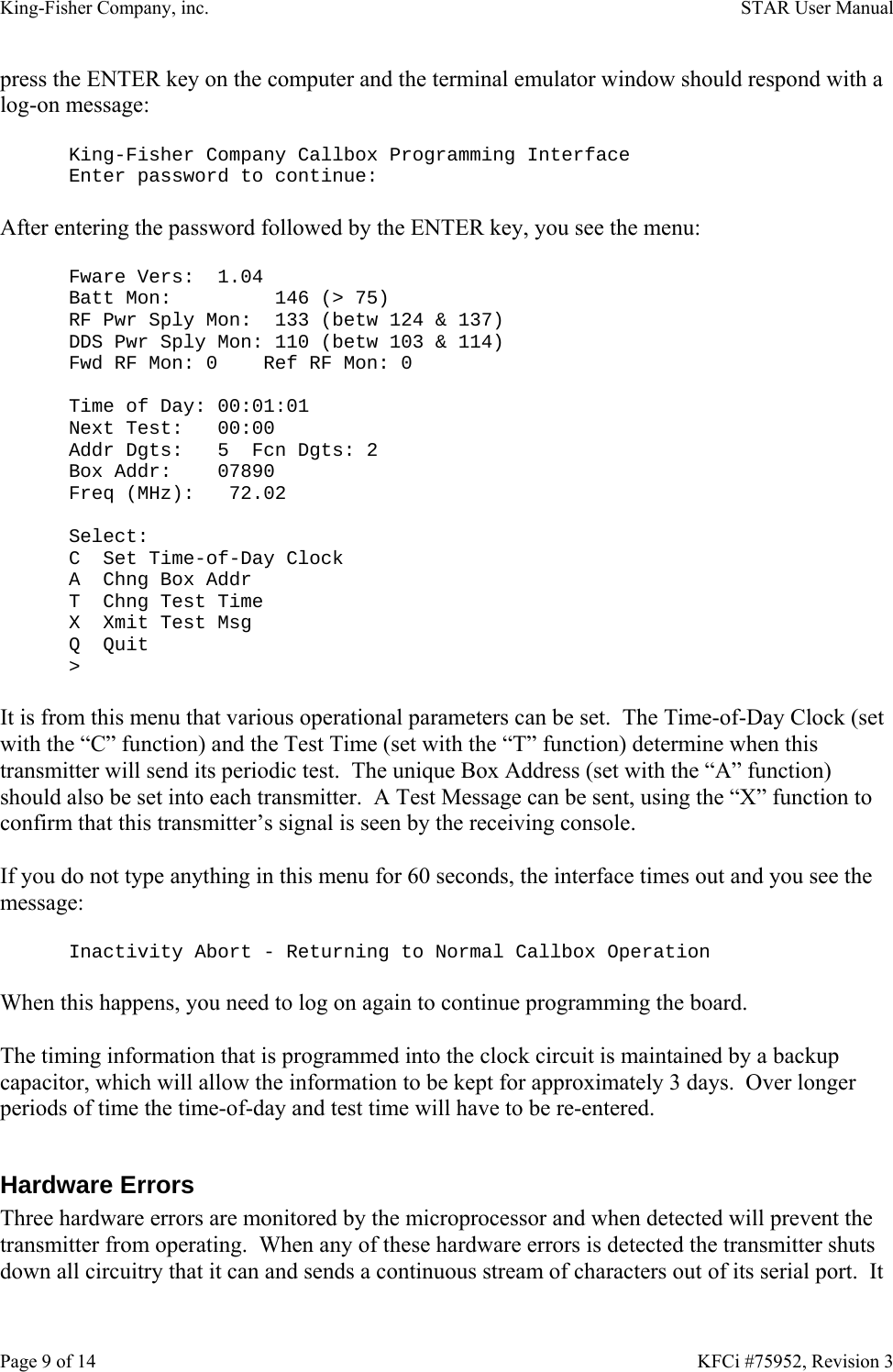
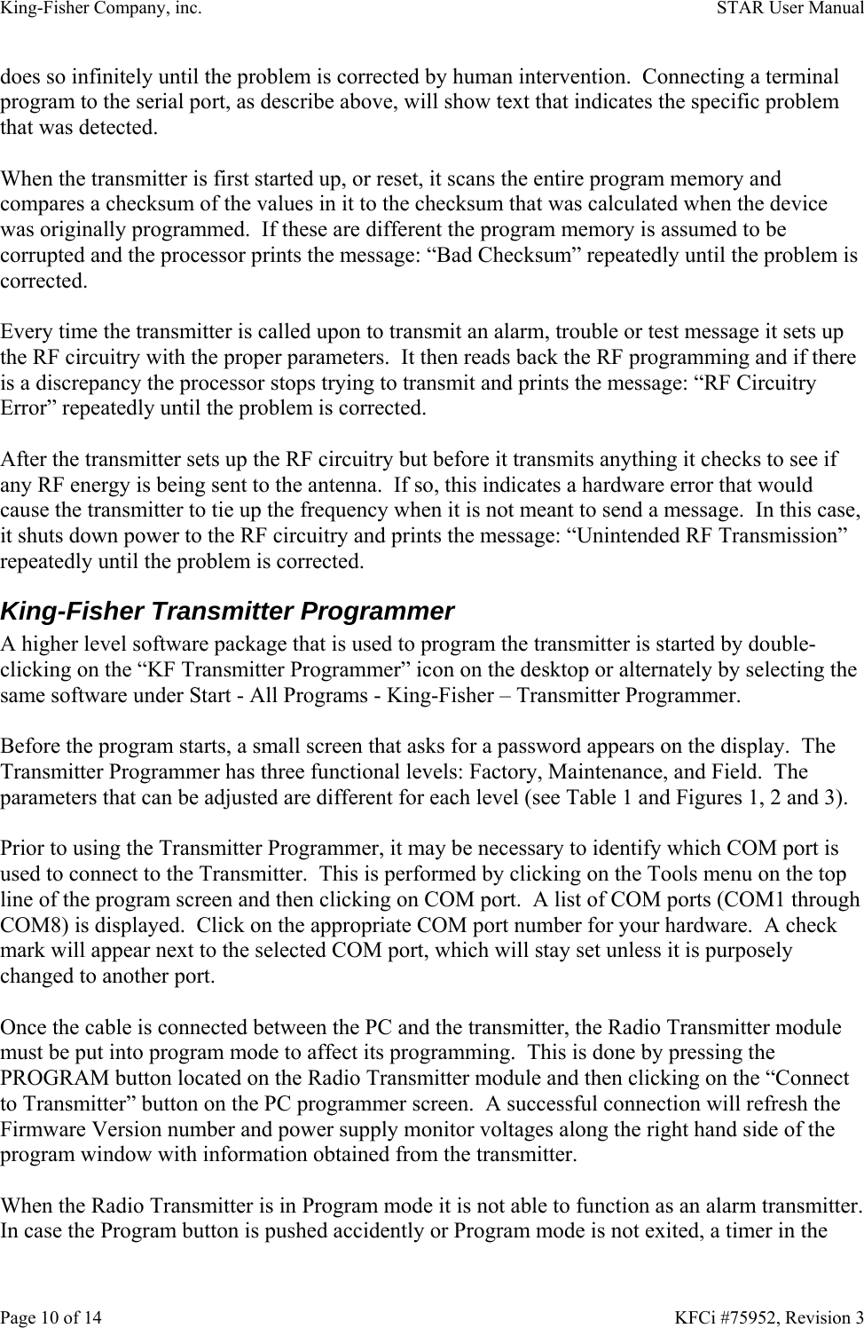
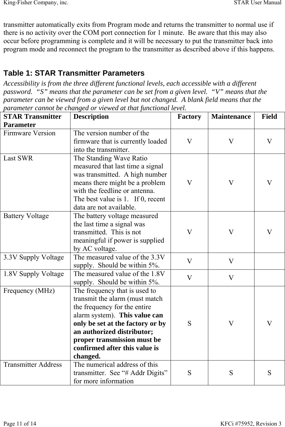
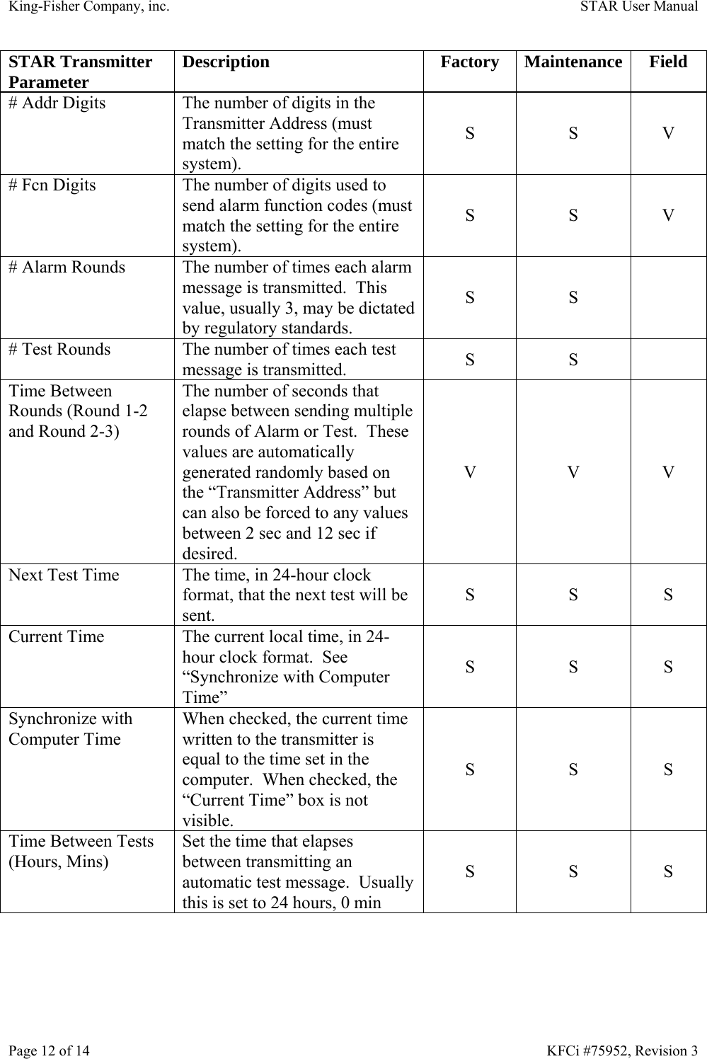
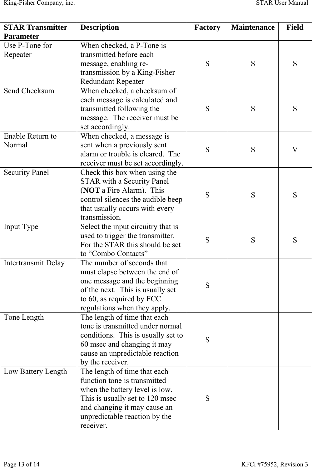
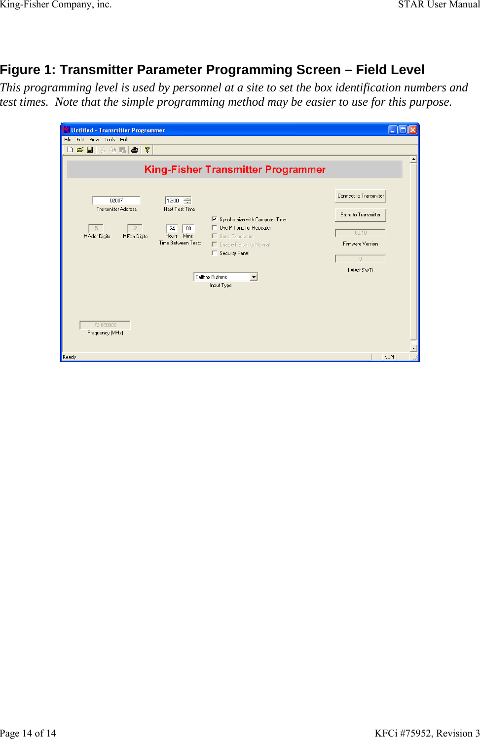
King-Fisher Company, Inc Radio Fire Alarm Panel Users Manual

Users Manual

STAR King-Fisher Company, inc. 2350 Foster Ave.            Wheeling, Il. 60090— 6574 Phone (847)398-7100           Fax (847)255-1507 Phone (888)687-5324(US)  Fax (877)687-5324(US)                    E-MAIL: sales@kfci.us    WEBSITE: www.kfci.com   KFCi #75952, Revision 2        Radio Fire Alarm           User Manual
Page 1 of 14    KFCi #75952, Revision 3 King-Fisher Company, inc STAR Radio Fire Alarm User Manual KFCi #75952   Table of Contents Revision History ............................................................................................................................. 1 FCC Device Statements .................................................................................................................. 2 Introduction..................................................................................................................................... 2 STAR Operational Specifications............................................................................................... 3 Alarm Interface ....................................................................................................................... 3 Power Sources......................................................................................................................... 3 Indicators................................................................................................................................. 3 Adjustments ............................................................................................................................ 3 Radio....................................................................................................................................... 4 Environmental......................................................................................................................... 4 STAR Basic Connections ............................................................................................................... 4 AC Power.................................................................................................................................... 4 Antenna....................................................................................................................................... 4 Alarm Wiring.............................................................................................................................. 5 Battery......................................................................................................................................... 5 STAR Interface Module.................................................................................................................. 5 System Power Supply ................................................................................................................. 5 Connecting Alarm Inputs............................................................................................................ 6 Zone Programming ..................................................................................................................... 7 STAR Radio Transmitter Module...................................................................................................8 Programming the Transmitter.....................................................................................................8 Simple Interface.......................................................................................................................... 8 Hardware Errors...................................................................................................................... 9 King-Fisher Transmitter Programmer....................................................................................... 10 Table 1: STAR Transmitter Parameters................................................................................ 11 Figure 1: Transmitter Parameter Programming Screen – Field Level.................................. 14  Revision History Rev Date  Author  Description 0  7/11/08  Gregory Lapin  Initial Release 1  3/2/09  Gregory Lapin  Changes based on FM testing 2  6/12/09  Gregory Lapin  Changes required following FCC testing 3  6/29/09  Gregory Lapin  Description of hardware error checking and Low/High band.
King-Fisher Company, inc.    STAR User Manual Page 2 of 14    KFCi #75952, Revision 3 FCC Device Statements FCC ID: AGJ-KFSTARLB0001  WARNING: Changes or modifications not expressly approved by King-Fisher Company, inc could void the user's authority to operate this equipment.  NOTE: This equipment has been tested and found to comply with the limits for a Class B digital device, pursuant to Part 15 of the FCC Rules.  These limits are designed to provide reasonable protection against harmful interference in a residential installation.  This equipment generates, uses and can radiate radio frequency energy and, if not installed and used in accordance with the instructions, may cause harmful interference to radio communications.  However, there is no guarantee that interference will not occur in a particular installation.  If this equipment does cause harmful interference to radio or television reception, which can be determined by turning the equipment off and on, the user is encouraged to try to correct the interference by one or more of the following measures: ¾ Reorient or relocate the receiving antenna. ¾ Increase the separation between the equipment and receiver. ¾ Connect the equipment into an outlet on a circuit different from that to which the receiver is connected. ¾ Consult the dealer or an experienced radio/TV technician for help. Introduction The STAR Radio Fire Alarm (KFCi #99952) is a self-contained Auxiliary Signaling Device that responds to contact closures from standard fire panels, emergency switch devices, supervisory switch devices and auxiliary switch devices to generate an alarm message in a standard King-Fisher KFRA-C receiving processing unit format and transmits that message by radio.  The STAR is contained in a NEMA-1 cabinet and derives power from a 120VAC circuit.  It maintains a backup battery, periodically checking its status and supplying charging voltage to keep the battery fully charged.   The STAR can operate from its battery in standby mode for 96 hours following a power failure.  The STAR will generate a trouble message if it detects loss of AC power, disconnection of the battery, a battery that does not hold a charge, or a break in any of the input connections.  To prevent spurious trouble messages, a confirmation wait time of 60 sec is applied.  If the fault exists for at least 60 sec only then is a trouble message transmitted.  This prevents excessive trouble message signals during normal maintenance, such as changing a battery or short duration power failures.  There are two basic units that make up the STAR subsystem.  An Interface circuit controls the power subsystem and monitors up to six Class B monitored inputs.  It applies debounce logic to signals on these inputs to prevent responding to external noise, such as that due to lightning strikes in the area.  When an alarm is warranted, the interface triggers the radio transmitter control circuitry to initiate the transmission of the alarm message.  The radio circuitry monitors input signals and builds an alarm message that it transmits on a preselected VHF radio frequency channel.  Several alarm message formats that conform to an
King-Fisher Company, inc.    STAR User Manual Page 3 of 14    KFCi #75952, Revision 3 existing King-Fisher messaging standard can be selected.  Message format specifics are selected by the alarm technician using a laptop computer. STAR Operational Specifications Alarm Interface Monitored Dry Contact Inputs  6 Monitored Local Energy Input  1 Input Termination Resistance  10 kΩ Dry Contact Trouble Output  1 Ground Fault Detection Resistance  < 100 Ω Input Debounce Time  1 – 65535 msec Power Sources AC Voltage Range  80-135 VAC AC Frequency  50-60 Hz AC Current Draw  < 0.5 A AC Fuse  1A Backup Battery Type  Sealed Lead Acid Backup Battery Voltage  13.0 V nominal Backup Battery Standby Duration  > 72 Hr (2.5 A-Hr, such as KFCi BP-1225) > 96 Hr (5.0 A-Hr, such as KFCi BP-1205) Backup Battery Recharge Duration  < 24 Hr Battery Fuse  2ASB Low Battery Indication Threshold  12.6 V ± 0.1 V Battery Cutoff Threshold  11.3 V ± 0.1 V Indicators AC Power Present  Green LED on Interface Module Power Trouble  Flashing Yellow LED on Interface Module Alarm Input  Red LED, adjacent to each input on Interface Module Input Trouble  Yellow LED, adjacent to each input on Interface ModuleTransmission in Progress  Green LED, on solid, on Transmitter Module Transmission Waiting  Green LED, blinking, on Transmitter Module Transmission in Progress  Beeper on Transmitter Module Adjustments Battery Charging Voltage  Potentiometer on Interface Module Frequency Trim  Potentiometer on Transmitter Module Transmit Test  Black Button on Interface Module Program Transmitter  Black Button on Transmitter Module Interface Module Reset  White Button on Interface Module Transmitter Module Reset  White Button on Transmitter Module
King-Fisher Company, inc.    STAR User Manual Page 4 of 14    KFCi #75952, Revision 3 Radio Frequency Range:  FCC  NTIA 72 - 76 MHz 138-174 MHz Frequency Resolution  1 Hz Frequency Stability  ± 5 ppm Spurious Emissions  < -50 dBc Power Output  0.5 – 0.8 watts peak Modulation AM Tone Frequency Range  50 Hz through 600 Hz Tone Frequency Resolution  0.1 Hz Tone Frequency Stability  ± 5 ppm Power Source  12 – 15 VDC Power Source Fuse  1A Current Draw – Standby  < 100 µA Current Draw – Transmission  < 1A Environmental Temperature Range – Operational  -40°C through 60°C Temperature Range – Storage  -40°C through 125°C Humidity  < 95% non-condensing  STAR Basic Connections The STAR cabinet is usually mounted on a wall with external wiring brought in through conduit connected through the sides or bottom of the cabinet.  It is recommended that conduit not be connected through the top wall of the cabinet.  There are several basic connections: AC Power 120V AC power, single phase, with a separate ground wire, is connected to the cabinet at a terminal block in the upper left corner of the subplate.  Hot, neutral and ground wires should be inserted to the appropriately marked terminals and screwed down tightly.  Wires can be any size up to 10 AWG and can be either solid or stranded copper. Antenna There are two ways to connect an antenna to the STAR.  All antennas and feedlines must be 50Ω.  The STAR is shipped with a coaxial jumper wire connecting the transmitter output to a BNC connector mounted in the upper right surface of the cabinet.  A BNC (or BNX) antenna or feedline can be attached to this connector.  Alternately, a 50Ω coax feedline can be brought in through a conduit attached to the sides or bottom of the cabinet and connected directly to the BNC connector in the upper right corner of the STAR Transmitter board.
King-Fisher Company, inc.    STAR User Manual Page 5 of 14    KFCi #75952, Revision 3 Alarm Wiring Supervised alarm wiring is connected to a terminal block on the left side of the STAR Interface board.  Termination requirements are described below. Battery A backup battery sits in the bottom of the cabinet and connects to the STAR Interface board with a 3-pin Amp connector in the lower right corner.  Different backup battery types may be used but the basic requirements are as follows: a sealed lead acid battery must be used with a minimum capacity of 2.5 A-Hr.  The battery should be rated for both discharging and charging over the full temperature range that the STAR cabinet will be subjected to.  Typically, this is rated from -40°C (-40°F) to +60°C (+140°F).  Note that most gel cell sealed lead acid batteries are not capable of operation over this temperature range. STAR Interface Module The STAR Interface Module (KFCi #66951) provides monitored contact closure inputs for up to six connections.  Monitoring is based on a 10kΩ EOL resistor, which must be installed across the contacts.  If an input is unused, an EOL resistor must be installed across those input terminals.  A seventh input can be used to monitor a local energy master box input.  This input allows connections to an existing FACP’s L.E. Box trip circuit, if desired.  Jumper JP1 on the interface module selects whether or not the local energy input is used.  If not, the jumper must be in the Disable position; otherwise it must be in the Enable position.  Each input is translated to a function code that is recognized by the King-Fisher KFRA-C console.  There are 10 possible function codes and each of the inputs causes one of those function codes to be transmitted.  There is no limitation on the translation and it is possible that every input causes the same function code to be transmitted.  A programmable debounce time, measured in milliseconds, is also customizable for each input. System Power Supply The Interface module controls the power source for the STAR unit.  AC line power is supplied to the Interface after being fused and reduced in voltage by a transformer to 14-35 VAC.  The Interface module converts this to regulated DC, whose voltage is adjustable with potentiometer R76.  The desired operational voltage of the STAR is based on what is required to properly charge the battery.  The Interface module monitors AC voltage and switches the DC power source from the AC-to-DC power supply to the battery when it detects either a brownout condition or total loss of AC voltage.  Upon detecting these conditions the yellow Power Fault LED flashes every second.  When on battery power, the interface module continues to monitor both the AC voltage, to look for return of AC power, and the DC voltage, to insure that the battery does not become so depleted that it is damaged.  There are two operational battery levels that are acted upon by the STAR subsystem.  When the battery reaches the Low Battery threshold, all messages sent by the STAR are encoded to also report a Low Battery condition.  Later, when the battery is further
King-Fisher Company, inc.    STAR User Manual Page 6 of 14    KFCi #75952, Revision 3 depleted and its voltage reaches the Battery Cutoff threshold, the STAR shuts itself down to prevent excessive depletion of the battery (Note that even after the battery is not being drained by the STAR, its internal resistance causes it to continue to lose charge slowly.  It is important to recharge the battery soon after shut down to prevent damage to its cells).  In this condition the trouble contacts are closed and can be used to indicate to the associated panel that the STAR is no longer operational.  When AC is present, every two minutes the STAR removes the battery charging voltage and tests to see if the battery is holding a charge.  If not, the implication is either that the battery is faulty and needs to be replaced or that the battery has been removed, one of its wires has broken, or the battery fuse is blown.  Any of these conditions requires attention and the STAR indicates power trouble with the flashing Yellow LED and also transmits a trouble message to the KFRA-C after the desired debounce delay has passed. Connecting Alarm Inputs A 12-position pluggable terminal strip connector on the left edge of the Interface module is used to connect to dry contacts from a fire panel.  Each pair of contacts should be connected to the two sides of one dry contact.  There is no preferred polarity to this connection.  There are six such “zones” in the 12 connections.  Two indicator lights are located immediately to the left of each pair of contacts on the pluggable terminal strip connector: Red indicates when the input is in an Alarm condition (dry contact closure), Yellow indicates when the input is in a Trouble condition (wire breakage or ground fault).  Ground faults are detected individually by each input zone.  All input zones must be connected to a 10 kΩ termination resistor.  The termination resistor must be placed at the dry contacts.  If the input zone is not used the termination resistor leads must be inserted directly into the pluggable terminal strip connector.  If no termination resistor is connected to an input that zone will be in trouble.  All of the trouble indications are combined to create a single input trouble condition.  That can be transmitted as any function in the wireless system with a response delay of up to 65 seconds.  Thus, the Interface module can be programmed not to respond to a trouble condition unless it remains in trouble for a period of time.  This feature serves to prevent spurious trouble messages when work is being done on the system.  A separate two-contact pluggable terminal strip connector adjacent to the input connector gives access to a dry contact trouble relay that can be wired back to an input on the fire panel.  This contact closure occurs when the STAR is in power trouble.  It is normally-closed so if all power to the STAR is lost, both AC loss and a dead battery, the panel will be able to detect this.  Another two contact pluggable terminal strip connector is used to connect to a Local Energy Master Box trip circuit.  There is no preferred polarity to this connection.  When a Local Energy Master Box connection is used, a jumper must be placed across the center and right hand posts of J9.  Alternately, if this connection is not used, the jumper must be moved to the center and left hand posts of J9 to disable it.
King-Fisher Company, inc.    STAR User Manual Page 7 of 14    KFCi #75952, Revision 3 Zone Programming The response to a zone alarm can be programmed to elicit many responses on the KFRA-C receiving console.  To customize the parameters of the interface board it is first necessary to connect to the programming interface of the card.  The computer is connected to the STAR Interface module via an available COM-port, using a King-Fisher programming cable (KFCi #57950).  For computers that only have USB ports and no COM ports, a commercial USB-to-COM port converter can be used.  Any program that allows users to read and enter characters that pass through a computer’s COM port can be used to perform simple programming functions for the STAR Interface.  Once such a program is initiated and connected to the proper COM port press the PROGRAM button on the STAR transmitter board until the green light on the board is illuminated.  Once this occurs press the ENTER key on the computer and the terminal emulator window should respond with a log-on message:  King-Fisher Company Interface Programmer Enter password to continue:  After entering the password followed by the ENTER key, you see the menu:  Fware Vers 1.06 Batt Mon  173 (> 87)  Zone   Tone Debounce(msec) 0 (TRB)   7     20000 1         0       200 2         1       200 3         2       200 4         3       200 5         4       200 6         5       200 7 (LE)    6       200 8 (BAT)   7     30000 9 (PWR)  10     60000  A. InterAlarm Delay      2 sec B. Battery Test Period  90 sec Z. Chng Zone Defn S. Store Chnges in Interface X. Xmit Test Msg Q. Quit >  The adjustable parameters are defined as follows: ¾ InterAlarm Delay – the minimum time to responds between two alarms that come in together. ¾ Battery Test Period – the amount of time that elapses between tests of the battery.  Should be less than 120 sec. ¾ Chng Zone Defn – defines the response to alarms and troubles from the input zones.  Each zone is customized with the tone that is generated when the input becomes active and the “Debounce” delay in milliseconds that defines how long the active input must be
King-Fisher Company, inc.    STAR User Manual Page 8 of 14    KFCi #75952, Revision 3 stable before it is considered to be truly active.  The Tones 0 though 9 are generally predefined on the KFRA-C console.  A special tone 10 generates a two-tone sequence that is usually used to indicate power trouble.  Any zone can be programmed to send any tone. o Zone 0 is the generic zone for all input troubles. o Zones 1-6 are the input zones on connector J5. o Zone 7 is the local energy input on connector J7. o Zone 8 is activated when there is battery trouble. o Zone 9 is activated when there is AC power trouble. ¾ Store Chnges in Interface – once the changes to the timing and zone definitions are completed, the “S” function must be executed to make them permanent. ¾ Xmit Test Msg – transmits a test message through the transmitter, which send the number of rounds defined for testing. ¾ Quit – when you are done looking at or updating the interface specifications this returns the interface to operational status and the yellow LED goes off.  When in the menu if you do not type anything for 60 seconds, the interface times out and you see the message:  Inactivity Abort - Returning to Normal Callbox Operation  If you want to continue programming interface options you should simply press the ENTER key and log in again if this occurs. STAR Radio Transmitter Module The STAR Radio Transmitter module (KFCi #66950) is a microprocessor-controlled device that responds to contact-closure style inputs, generates an appropriate alarm message and transmits the message in a desired protocol on a software-generated VHF frequency. Programming the Transmitter Most of the specific details of the transmission format are selected from a software screen that is run in a PC-compatible computer running Windows 98 or higher operating system.  The computer is connected to the Radio Transmitter module via an available COM-port, using a King-Fisher programming cable (KFCi #57950).  For computers that only have USB ports and no COM ports, a commercial USB-to-COM port converter can be used.  There are two software interfaces available for both the Interface and the Transmitter boards.  The simple interface uses any terminal emulator, such as HyperTerminal, which is included with most Windows®-based computers. Simple Interface Any program that allows users to read and enter characters that pass through a computer’s COM port can be used to perform simple programming functions for the STAR Transmitter.  Once such a program is initiated and connected to the proper COM port press the PROGRAM button on the STAR transmitter board until the green light on the board is illuminated.  Once this occurs
King-Fisher Company, inc.    STAR User Manual Page 9 of 14    KFCi #75952, Revision 3 press the ENTER key on the computer and the terminal emulator window should respond with a log-on message:  King-Fisher Company Callbox Programming Interface Enter password to continue:  After entering the password followed by the ENTER key, you see the menu:  Fware Vers:  1.04 Batt Mon:         146 (> 75) RF Pwr Sply Mon:  133 (betw 124 & 137) DDS Pwr Sply Mon: 110 (betw 103 & 114) Fwd RF Mon: 0    Ref RF Mon: 0  Time of Day: 00:01:01 Next Test:   00:00 Addr Dgts:   5  Fcn Dgts: 2 Box Addr:    07890 Freq (MHz):   72.02  Select: C  Set Time-of-Day Clock A  Chng Box Addr T  Chng Test Time X  Xmit Test Msg Q  Quit >  It is from this menu that various operational parameters can be set.  The Time-of-Day Clock (set with the “C” function) and the Test Time (set with the “T” function) determine when this transmitter will send its periodic test.  The unique Box Address (set with the “A” function) should also be set into each transmitter.  A Test Message can be sent, using the “X” function to confirm that this transmitter’s signal is seen by the receiving console.  If you do not type anything in this menu for 60 seconds, the interface times out and you see the message:  Inactivity Abort - Returning to Normal Callbox Operation  When this happens, you need to log on again to continue programming the board.  The timing information that is programmed into the clock circuit is maintained by a backup capacitor, which will allow the information to be kept for approximately 3 days.  Over longer periods of time the time-of-day and test time will have to be re-entered.  Hardware Errors Three hardware errors are monitored by the microprocessor and when detected will prevent the transmitter from operating.  When any of these hardware errors is detected the transmitter shuts down all circuitry that it can and sends a continuous stream of characters out of its serial port.  It
King-Fisher Company, inc.    STAR User Manual Page 10 of 14    KFCi #75952, Revision 3 does so infinitely until the problem is corrected by human intervention.  Connecting a terminal program to the serial port, as describe above, will show text that indicates the specific problem that was detected.  When the transmitter is first started up, or reset, it scans the entire program memory and compares a checksum of the values in it to the checksum that was calculated when the device was originally programmed.  If these are different the program memory is assumed to be corrupted and the processor prints the message: “Bad Checksum” repeatedly until the problem is corrected.  Every time the transmitter is called upon to transmit an alarm, trouble or test message it sets up the RF circuitry with the proper parameters.  It then reads back the RF programming and if there is a discrepancy the processor stops trying to transmit and prints the message: “RF Circuitry Error” repeatedly until the problem is corrected.  After the transmitter sets up the RF circuitry but before it transmits anything it checks to see if any RF energy is being sent to the antenna.  If so, this indicates a hardware error that would cause the transmitter to tie up the frequency when it is not meant to send a message.  In this case, it shuts down power to the RF circuitry and prints the message: “Unintended RF Transmission” repeatedly until the problem is corrected. King-Fisher Transmitter Programmer A higher level software package that is used to program the transmitter is started by double-clicking on the “KF Transmitter Programmer” icon on the desktop or alternately by selecting the same software under Start - All Programs - King-Fisher – Transmitter Programmer.  Before the program starts, a small screen that asks for a password appears on the display.  The Transmitter Programmer has three functional levels: Factory, Maintenance, and Field.  The parameters that can be adjusted are different for each level (see Table 1 and Figures 1, 2 and 3).  Prior to using the Transmitter Programmer, it may be necessary to identify which COM port is used to connect to the Transmitter.  This is performed by clicking on the Tools menu on the top line of the program screen and then clicking on COM port.  A list of COM ports (COM1 through COM8) is displayed.  Click on the appropriate COM port number for your hardware.  A check mark will appear next to the selected COM port, which will stay set unless it is purposely changed to another port.  Once the cable is connected between the PC and the transmitter, the Radio Transmitter module must be put into program mode to affect its programming.  This is done by pressing the PROGRAM button located on the Radio Transmitter module and then clicking on the “Connect to Transmitter” button on the PC programmer screen.  A successful connection will refresh the Firmware Version number and power supply monitor voltages along the right hand side of the program window with information obtained from the transmitter.  When the Radio Transmitter is in Program mode it is not able to function as an alarm transmitter.  In case the Program button is pushed accidently or Program mode is not exited, a timer in the
King-Fisher Company, inc.    STAR User Manual Page 11 of 14    KFCi #75952, Revision 3 transmitter automatically exits from Program mode and returns the transmitter to normal use if there is no activity over the COM port connection for 1 minute.  Be aware that this may also occur before programming is complete and it will be necessary to put the transmitter back into program mode and reconnect the program to the transmitter as described above if this happens.  Table 1: STAR Transmitter Parameters Accessibility is from the three different functional levels, each accessible with a different password.  “S” means that the parameter can be set from a given level.  “V” means that the parameter can be viewed from a given level but not changed.  A blank field means that the parameter cannot be changed or viewed at that functional level. STAR Transmitter Parameter  Description Factory Maintenance Field Firmware Version  The version number of the firmware that is currently loaded into the transmitter. V V V Last SWR  The Standing Wave Ratio measured that last time a signal was transmitted.  A high number means there might be a problem with the feedline or antenna.  The best value is 1.   If 0, recent data are not available. V V V Battery Voltage  The battery voltage measured the last time a signal was transmitted.  This is not meaningful if power is supplied by AC voltage. V V V 3.3V Supply Voltage  The measured value of the 3.3V supply.  Should be within 5%.  V V  1.8V Supply Voltage  The measured value of the 1.8V supply.  Should be within 5%.  V V  Frequency (MHz)  The frequency that is used to transmit the alarm (must match the frequency for the entire alarm system).  This value can only be set at the factory or by an authorized distributor; proper transmission must be confirmed after this value is changed. S V V Transmitter Address  The numerical address of this transmitter.  See “# Addr Digits” for more information S S S
King-Fisher Company, inc.    STAR User Manual Page 12 of 14    KFCi #75952, Revision 3 STAR Transmitter Parameter  Description Factory Maintenance Field # Addr Digits  The number of digits in the Transmitter Address (must match the setting for the entire system). S S V # Fcn Digits  The number of digits used to send alarm function codes (must match the setting for the entire system). S S V # Alarm Rounds  The number of times each alarm message is transmitted.  This value, usually 3, may be dictated by regulatory standards. S S  # Test Rounds  The number of times each test message is transmitted.  S S  Time Between Rounds (Round 1-2 and Round 2-3) The number of seconds that elapse between sending multiple rounds of Alarm or Test.  These values are automatically generated randomly based on the “Transmitter Address” but can also be forced to any values between 2 sec and 12 sec if desired. V V V Next Test Time  The time, in 24-hour clock format, that the next test will be sent. S S S Current Time  The current local time, in 24-hour clock format.  See “Synchronize with Computer Time” S S S Synchronize with Computer Time When checked, the current time written to the transmitter is equal to the time set in the computer.  When checked, the “Current Time” box is not visible. S S S Time Between Tests (Hours, Mins) Set the time that elapses between transmitting an automatic test message.  Usually this is set to 24 hours, 0 min S S S
King-Fisher Company, inc.    STAR User Manual Page 13 of 14    KFCi #75952, Revision 3 STAR Transmitter Parameter  Description Factory Maintenance Field Use P-Tone for Repeater When checked, a P-Tone is transmitted before each message, enabling re-transmission by a King-Fisher Redundant Repeater S S S Send Checksum  When checked, a checksum of each message is calculated and transmitted following the message.  The receiver must be set accordingly. S S S Enable Return to Normal When checked, a message is sent when a previously sent alarm or trouble is cleared.  The receiver must be set accordingly.S S V Security Panel  Check this box when using the STAR with a Security Panel (NOT a Fire Alarm).  This control silences the audible beep that usually occurs with every transmission. S S S Input Type  Select the input circuitry that is used to trigger the transmitter.  For the STAR this should be set to “Combo Contacts” S S S Intertransmit Delay  The number of seconds that must elapse between the end of one message and the beginning of the next.  This is usually set to 60, as required by FCC regulations when they apply. S   Tone Length  The length of time that each tone is transmitted under normal conditions.  This is usually set to 60 msec and changing it may cause an unpredictable reaction by the receiver. S   Low Battery Length  The length of time that each function tone is transmitted when the battery level is low.  This is usually set to 120 msec and changing it may cause an unpredictable reaction by the receiver. S
King-Fisher Company, inc.    STAR User Manual Page 14 of 14    KFCi #75952, Revision 3  Figure 1: Transmitter Parameter Programming Screen – Field Level This programming level is used by personnel at a site to set the box identification numbers and test times.  Note that the simple programming method may be easier to use for this purpose.

Navigation menu