Kirmuss and Associates Infinity Advanced Technologies KAPP1045UP Two Way Radio User Manual
Kirmuss & Associates / Infinity Advanced Technologies Two Way Radio
UserManual.wiki
>
Kirmuss and Associates Infinity Advanced Technologies
>
KAPP1045UP User Manual
User Manual
Navigation menu
Upload a User Manual
Namespaces
Wiki Guide
HTML
PDF
Info
Views
User Manual
Discussion / Help
Navigation
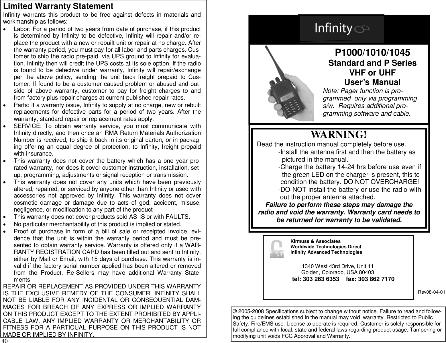
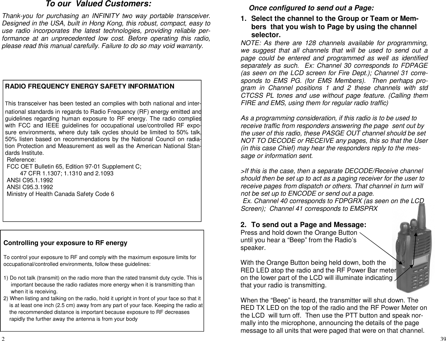
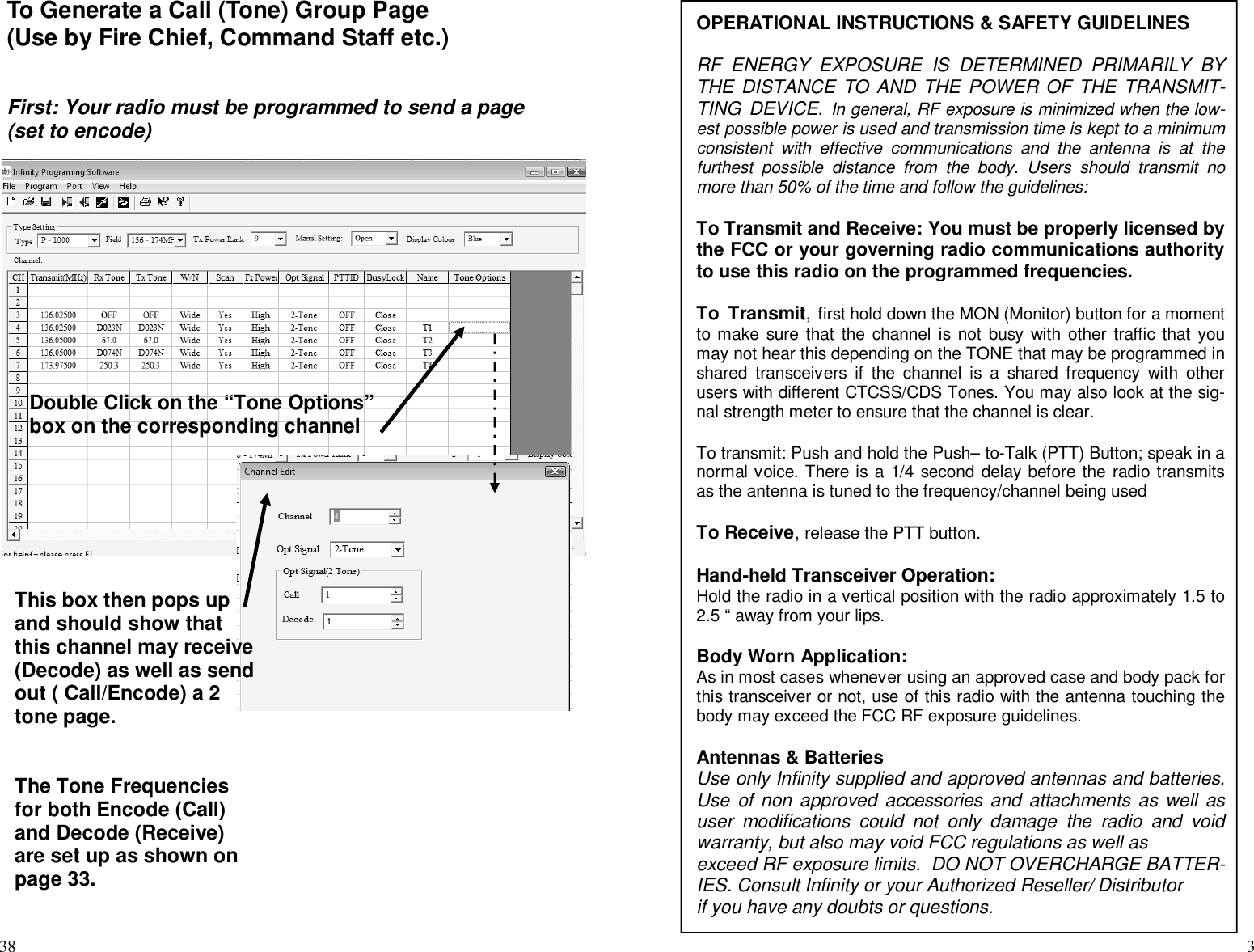
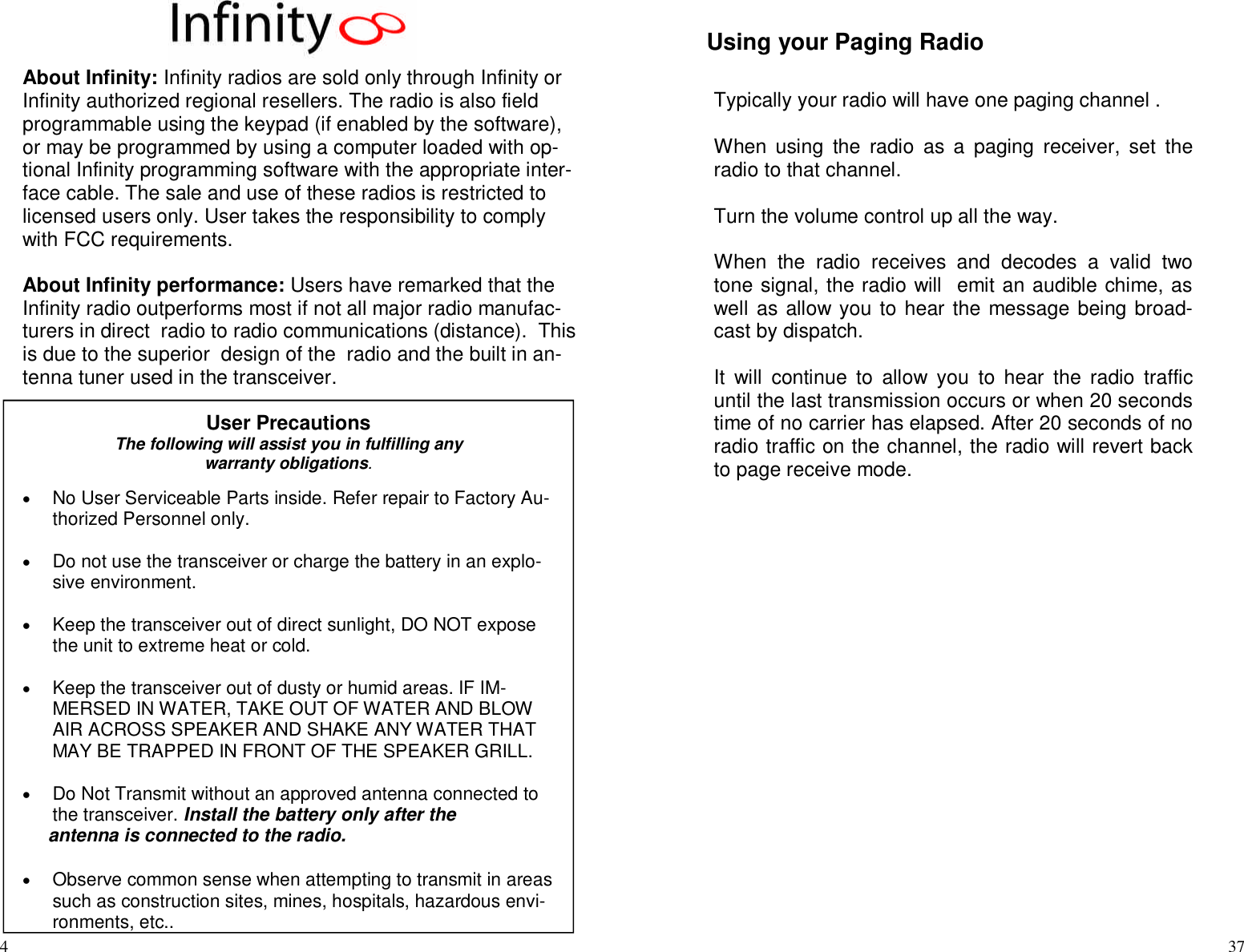
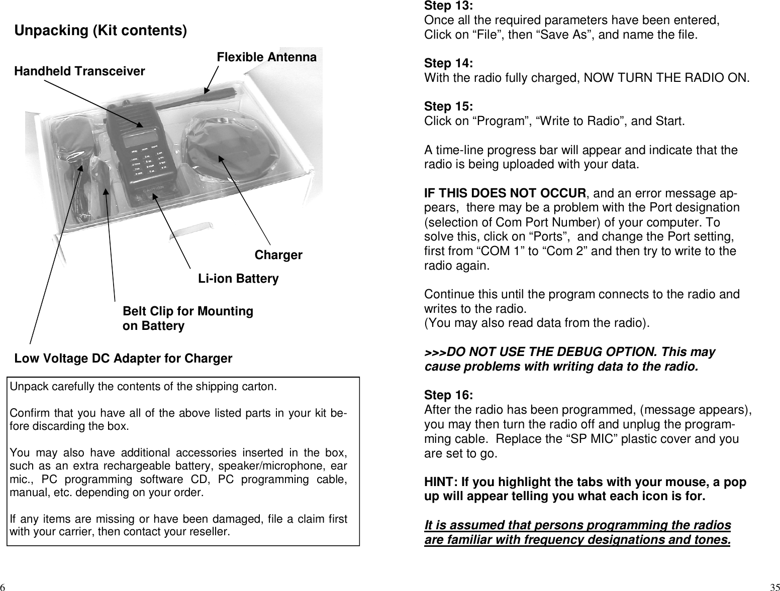
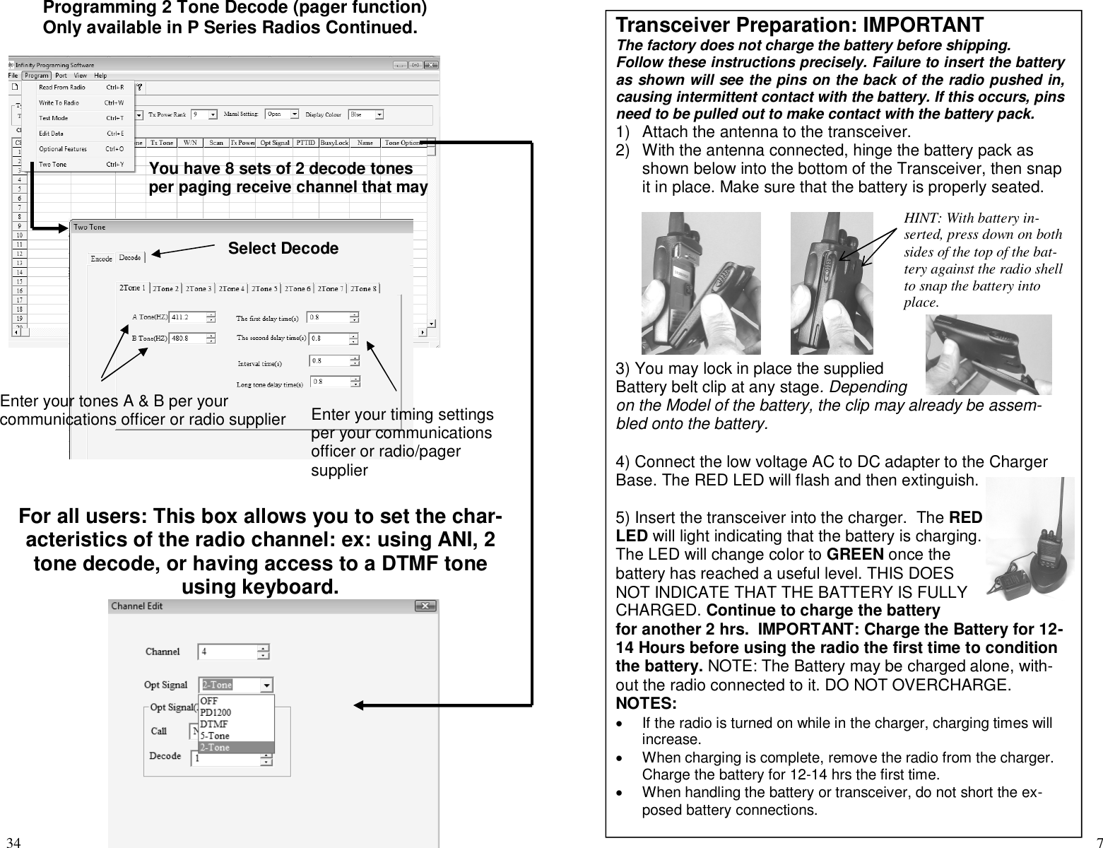
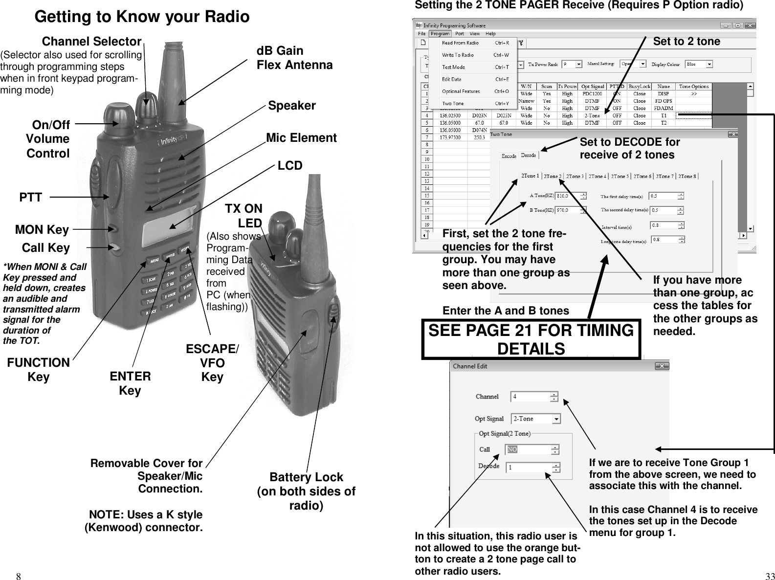
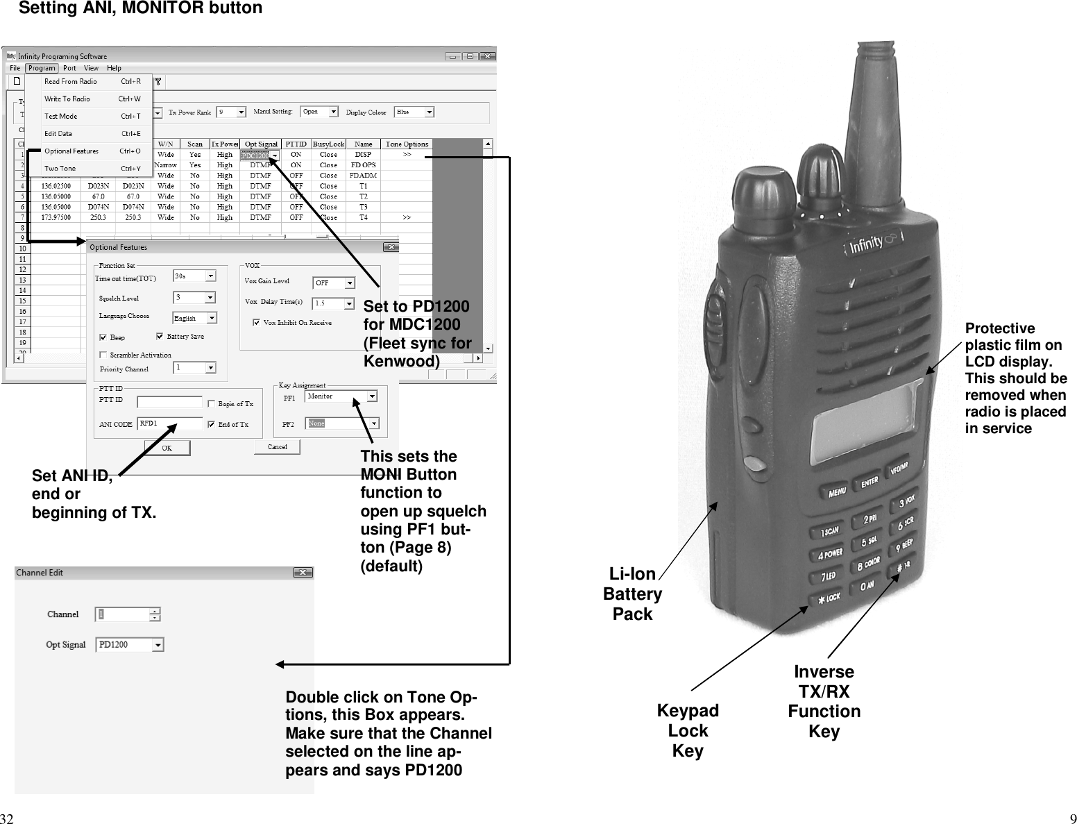
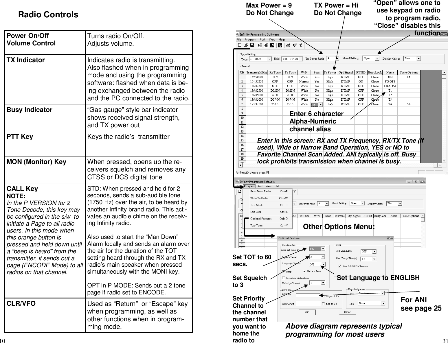
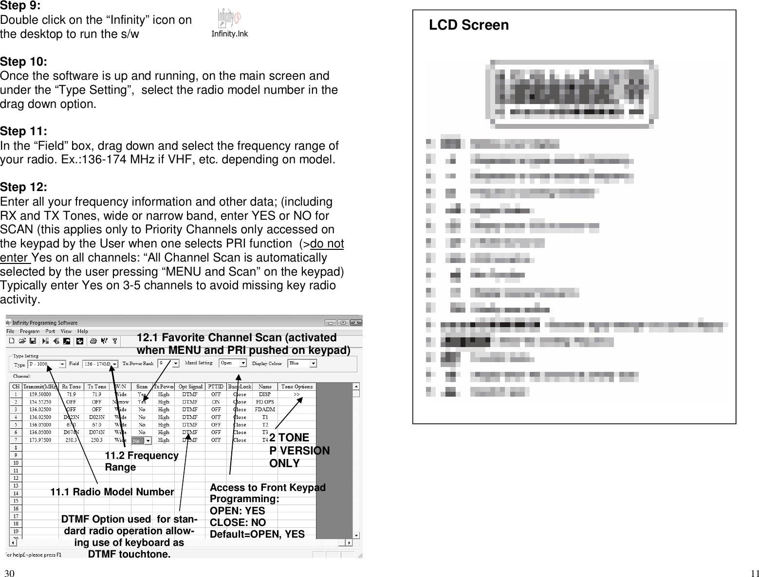
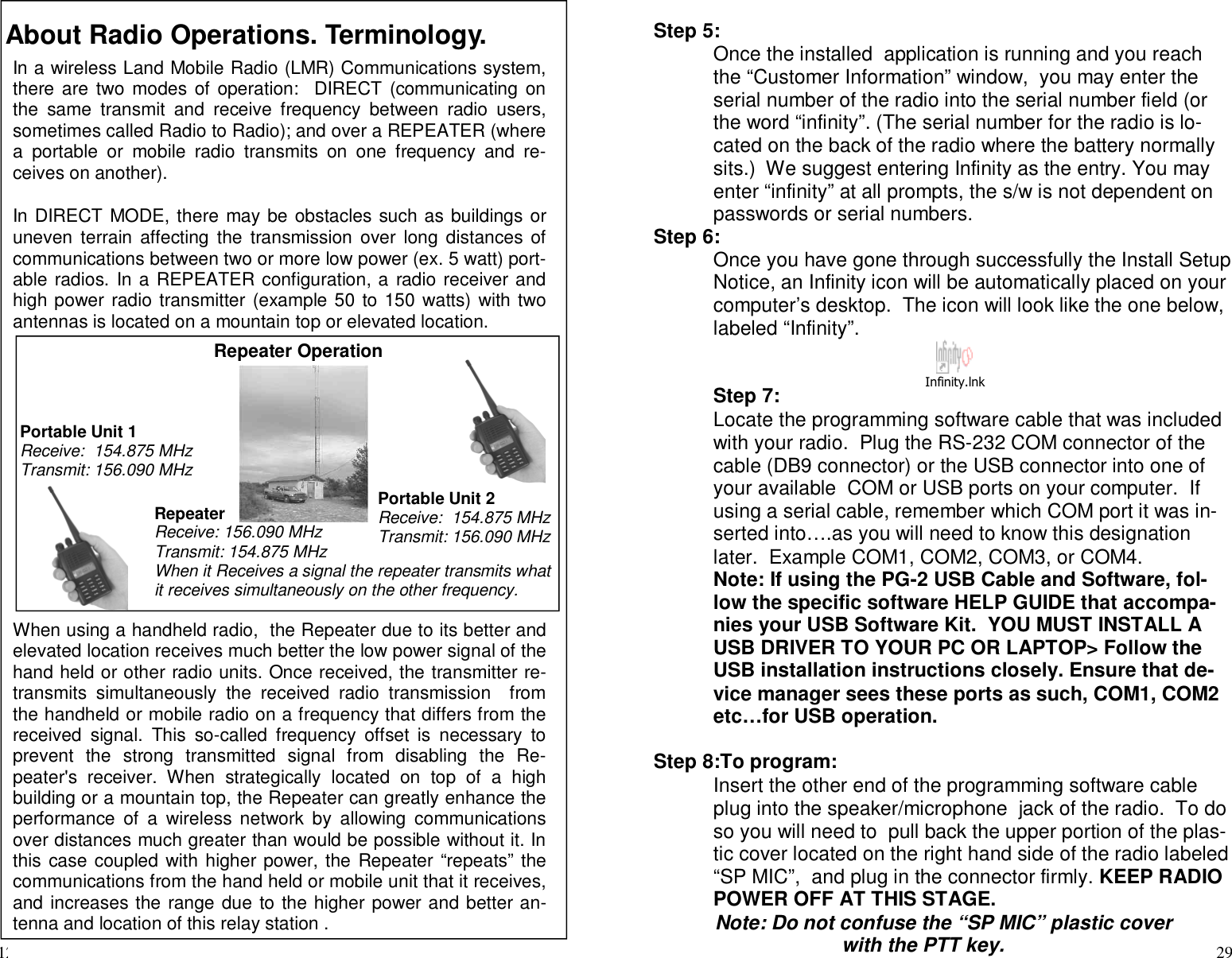
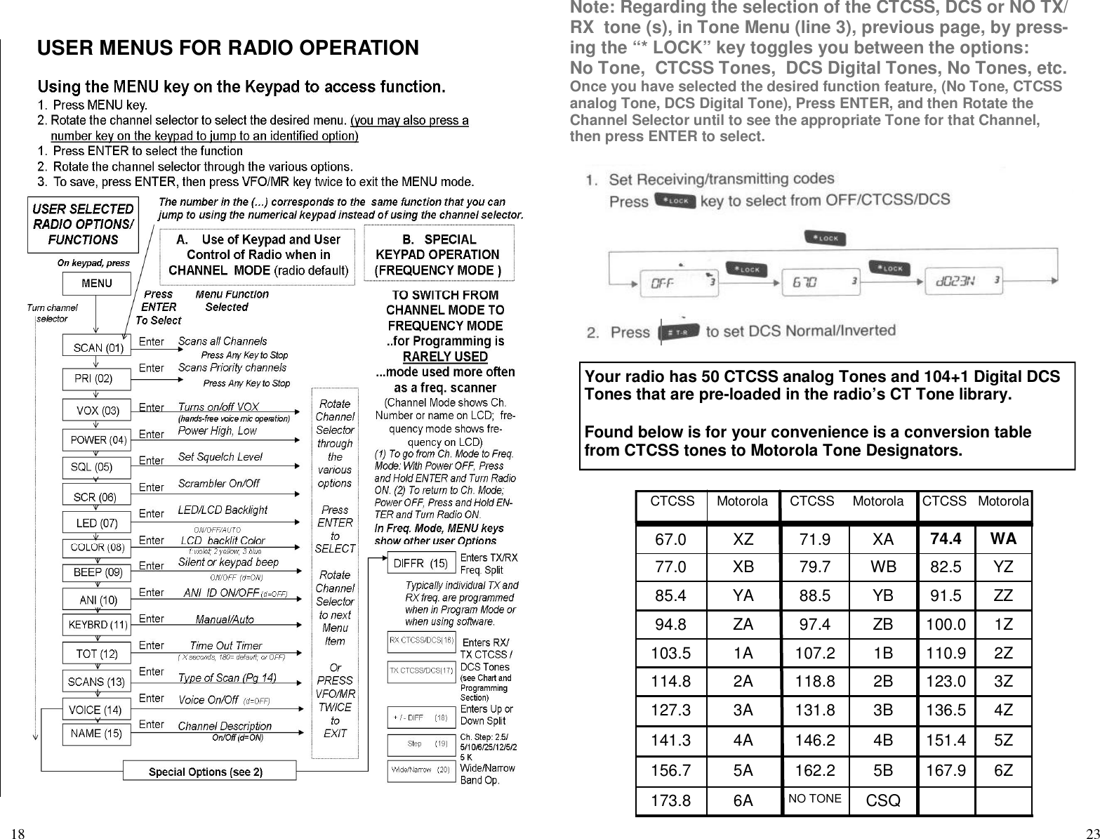
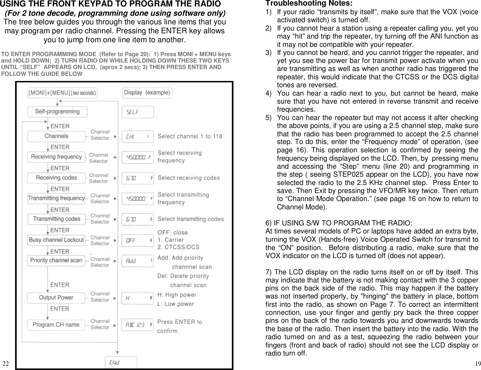
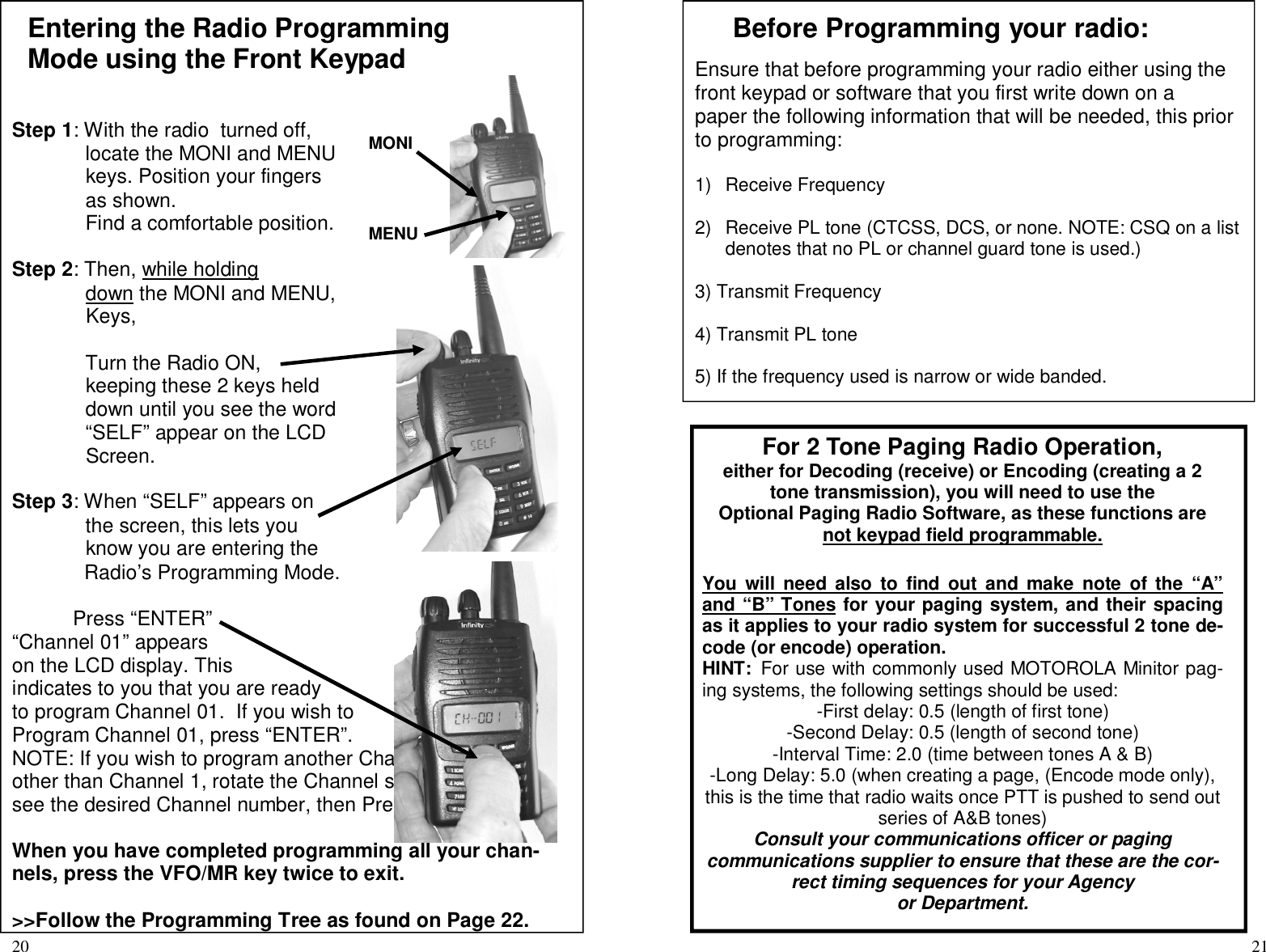
![36How to use your Paging RadioOnce programmed, your radio software programming for the PagingReceive model should look similar to the screens below. This illustra-tion is a sample scenario of a Chief’s radio.It is for illustration purposes only depicting typical radio applications ofthe P-1000/P1010 P Series radios with paging option.Examples:Channel 1 is a repeater channel for Dispatch, no paging receive, on scanChannel 2 is a weather channel with receive onlyChannel 3 is the main repeater channel where one can hear all activity, not onPRI scan. Hears all radio traffic and page tones. One hears all radio traffic forFire, Med, Public Works.Channel 4 is the Fire Channel with 2 Tone Decode for Fire, using the same re-peater as EMS and Public Works. On paging Receive, on PRI scan. Only firepage calls are heard.Channel 5 is the EMS channel with 2 tone decode for EMS/MED calls. Usessame repeater as Fire and Public Works. On paging receive, on PRI scan.Channel 6 is the Public Works channel with 2 tone decode for Public Works.On paging receive, not on PRI Scan.Channel 7 is a DOT channel with 2 tone paging receive, not on PRI scan.This is the Fire Chief’s radio:-Fire, EMS and Public Works use the same repeater.-When on PRI scan, his radio scans and listens for pages from both FIREand EMS. (Channels 4 and 5).-If he is on Channel 3, he hears all traffic, and all tones generated by thedispatcher ‘s paging terminal.>IF THE CHIEF’S RADIO WAS PROGRAMMED TO ENCODE, HECOULD THEN INITIATE A PAGE BY PRESSING AND HOLDING DOWNTHE ORANGE BUTTON ON THE RADIO ON THE APPROPRIATECHANNEL UNTIL HIS RADIO BEEPS AT HIM, INDICATING THAT APAGE WAS SUCCESFULLY SENT OUT. 5Product Features128 channels5 watt (VHF), 4 watt (UHF) power output2 Tone Decode and Encode (P-Option) 12.5 KHz narrow/ wi de band spaci ngwi th 2.5 KHz Channel stepANI ID code (check compatibility with your radiosystem)VOX operation (for hands free operation)LCD display with channel, frequency or Englishlanguage channel aliasScrambler (inverted type) operation (to keep con-versations and information secure)Three color selectable backlit LCDPersonal Emergency AlarmProgrammable by PC or Front Keypad* [*Keypadprogramming access may be locked out by thesoftware.]50 CTCSS ands 104 DCS Normal/Inverted tones,SelectableTime-out-timerBusy channel lock-outAudible function and channel number (feedback touser if enabled) in English language through ra-dio’s speaker](https://usermanual.wiki/Kirmuss-and-Associates-Infinity-Advanced-Technologies/KAPP1045UP/User-Guide-956931-Page-5.png)