Koden Electronics RB715L MODEL RA41C RADAR User Manual USERS MANUAL
Koden Electronics Co., Ltd MODEL RA41C RADAR USERS MANUAL
UserManual.wiki
>
Koden Electronics
>
RB715L User Manual
USERS MANUAL
Navigation menu
Upload a User Manual
Namespaces
Wiki Guide
HTML
PDF
Info
Views
User Manual
Discussion / Help
Navigation
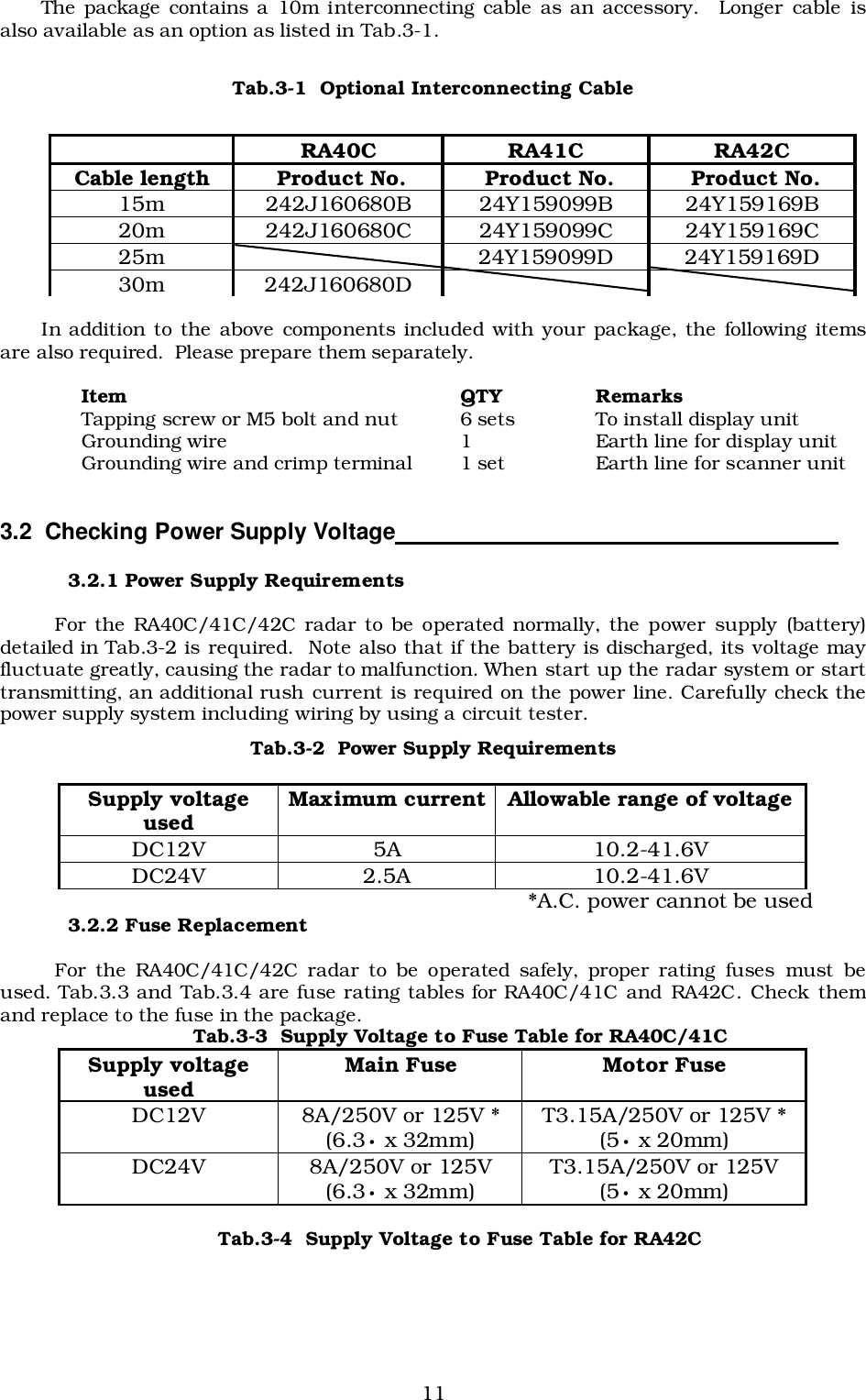
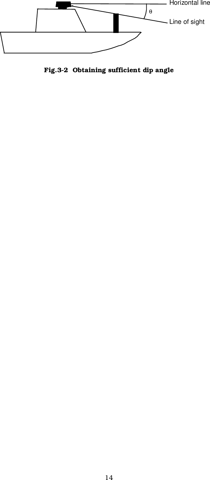
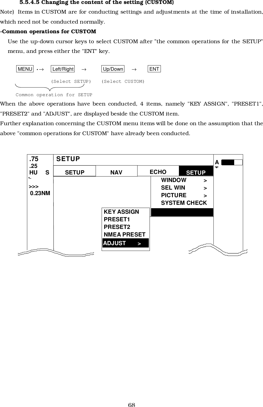
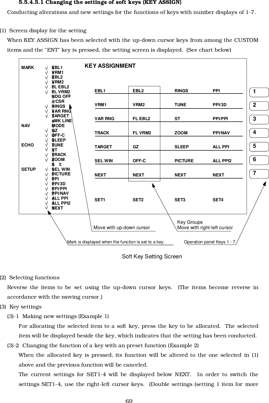
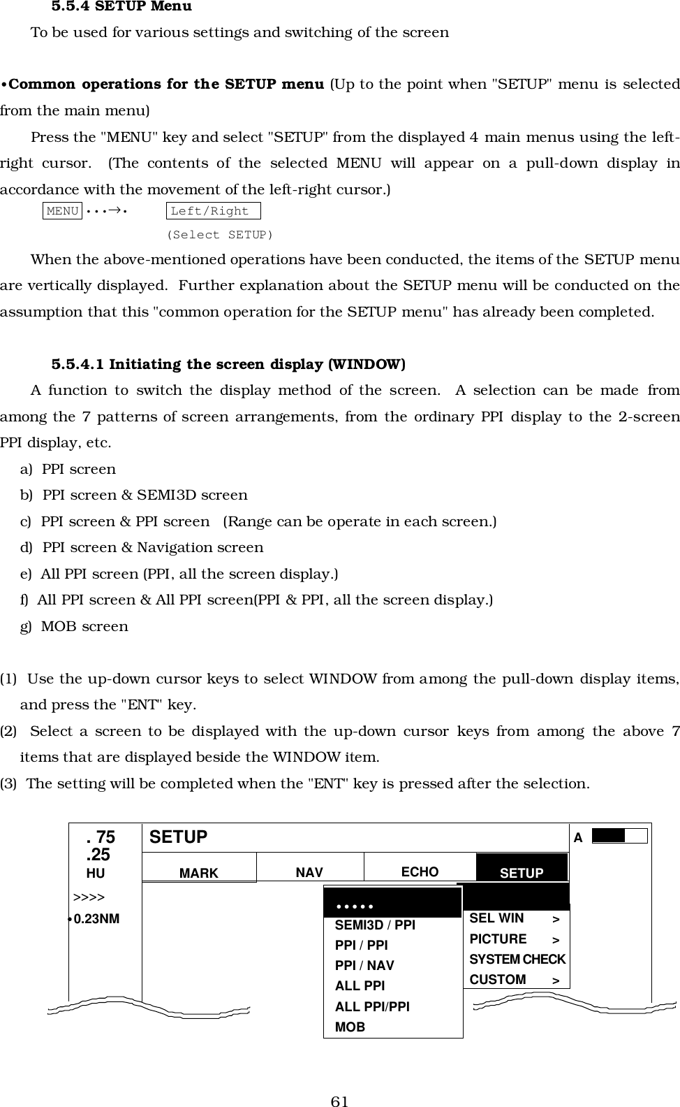
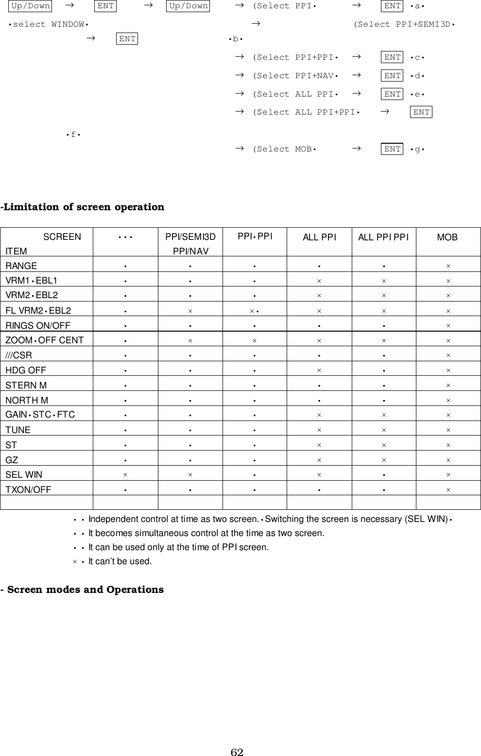
![13(a) A place where you can see the ship's bow when you raise your face from theradar screen.(b) A place where there is no direct sun-light to avoid display temperature up.(c) A place where there is good ventilation and minimum vibration.(d) A place where the display unit is apart more than the minimum safe dis-tance from a magnet compass as listed in Tab.3-5 below.Tab.3-5 Minimum Safe Distance from Magnetic Compass3.3.3 Shifting away from obstacles!!!! Shifting from keel lineBy shifting the scanner position from the keel line to the starboard side ofthe ship, it is possible to move shadow zones to the port side which makes itpossible to keep clear vision in the bow direction. The distance to be shifted canbe obtained by calculation depending on the distance from the scanner to obsta-cles using the following equation:Ls=0.4R+D/2 [m] (when R<15m)Ls=0.025R+D/2 [m] (when R>=15m)where Ls = distance to be shifted from keel lineD = diameter of obstacle on keel lineR = distance from scanner to obstacle"""" Obtaining sufficient dip angleRaise the scanner position so that there is a sufficient dip angle θ availablebetween the line of sight from the scanner to the obstacle and the horizontalline. By raising the dip angle above 5°, it is possible to prevent mid- and long-distance shadow zones. The radar cannot detect objects below the line of sight.Master compass Steering compassScanner unit 2.0m 1.4mDisplay unit 2.0m 1.4m Ls R D Scanner Unit Obstacle Keel line Fig.3-1 Shifting from keel line](https://usermanual.wiki/Koden-Electronics/RB715L/User-Guide-367260-Page-23.png)