L 3 Communications Avionics Systems TRC497 SkyWatch Traffic Advisory System User Manual COVER
L-3 Communications, Avionics Systems SkyWatch Traffic Advisory System COVER
Contents
- 1. Install Manual part 1 of 3
- 2. Install Manual part 2 of 3
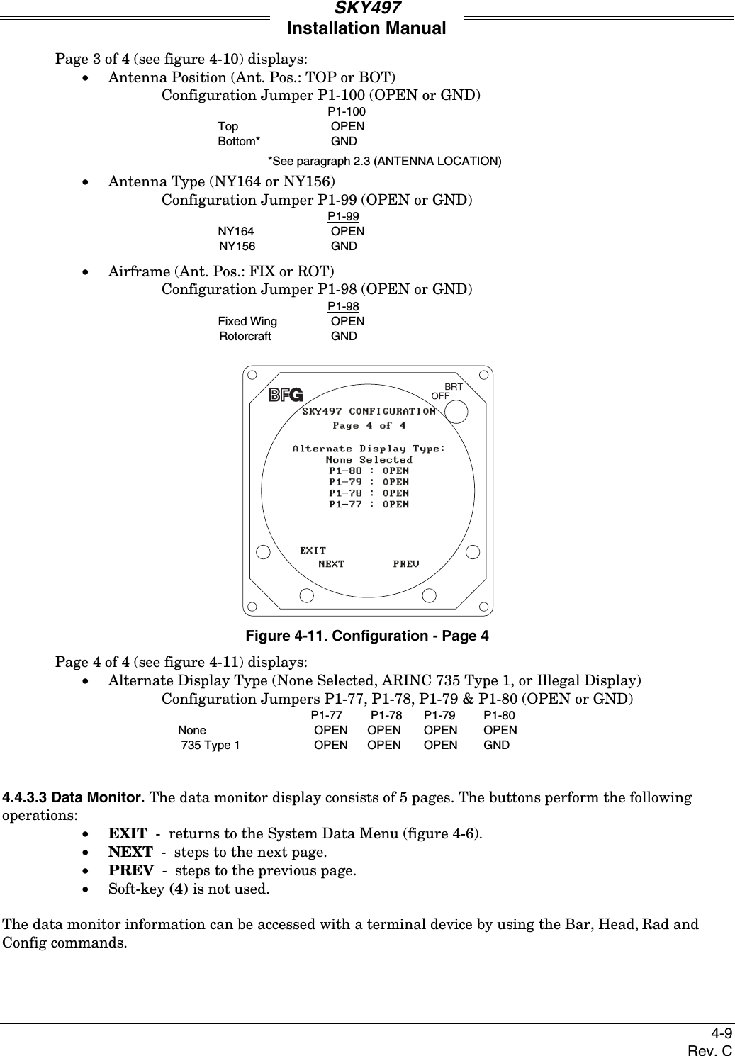
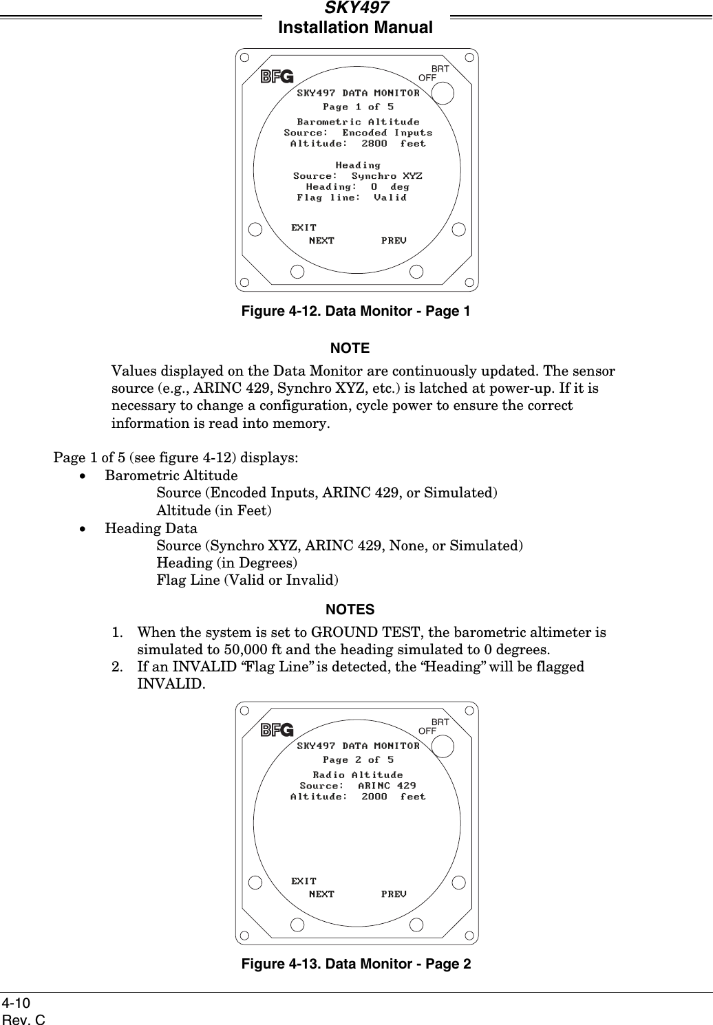
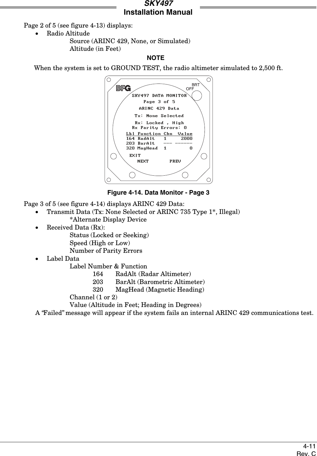
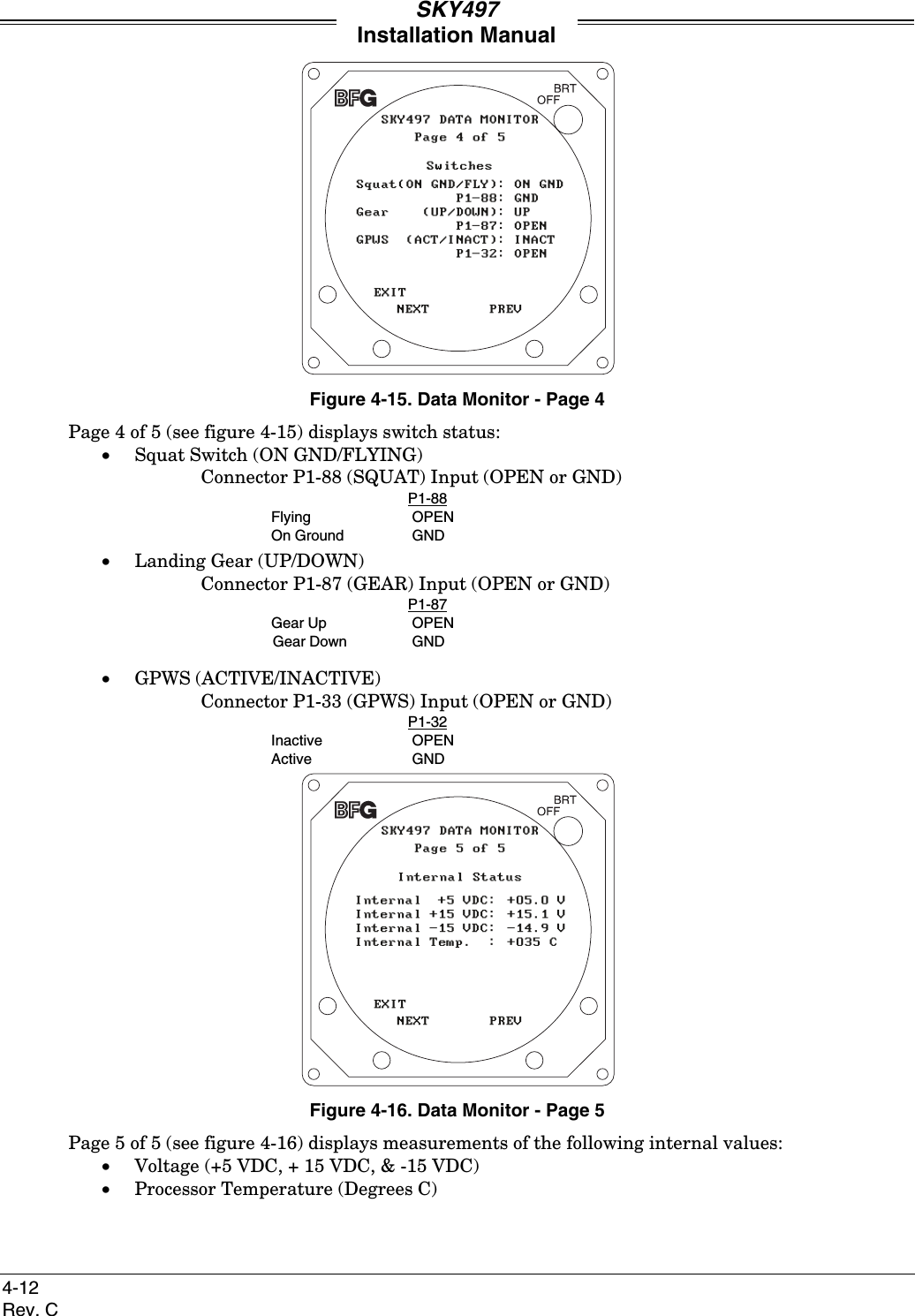
- 3. Install Manual part 3 of 3
- 4. Pilots Guide part 1 of 2
- 5. Pilots guide part 2 of 2
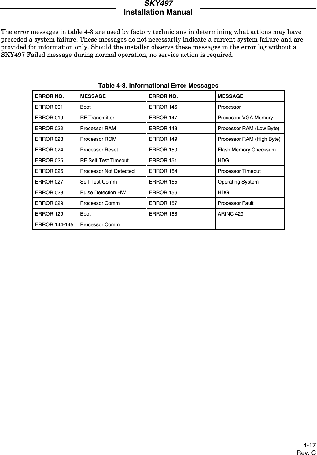
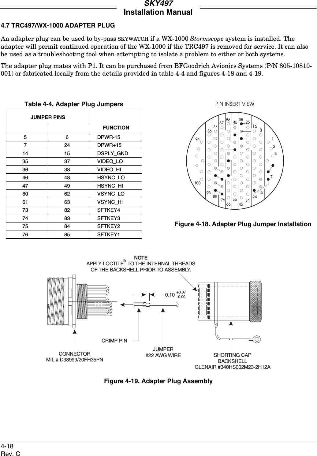
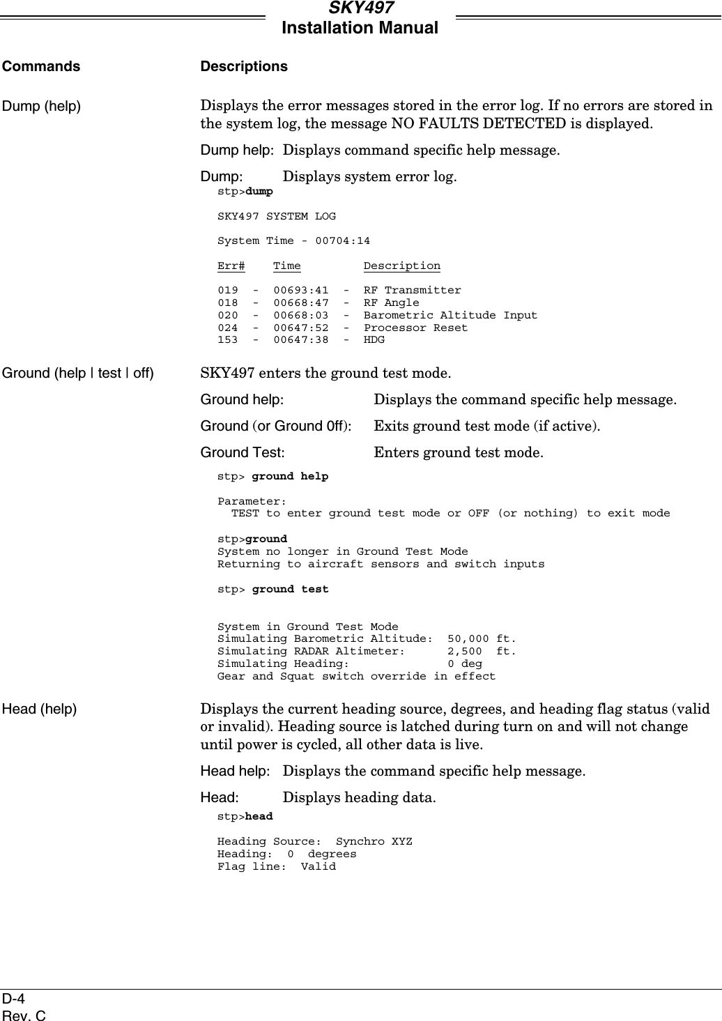
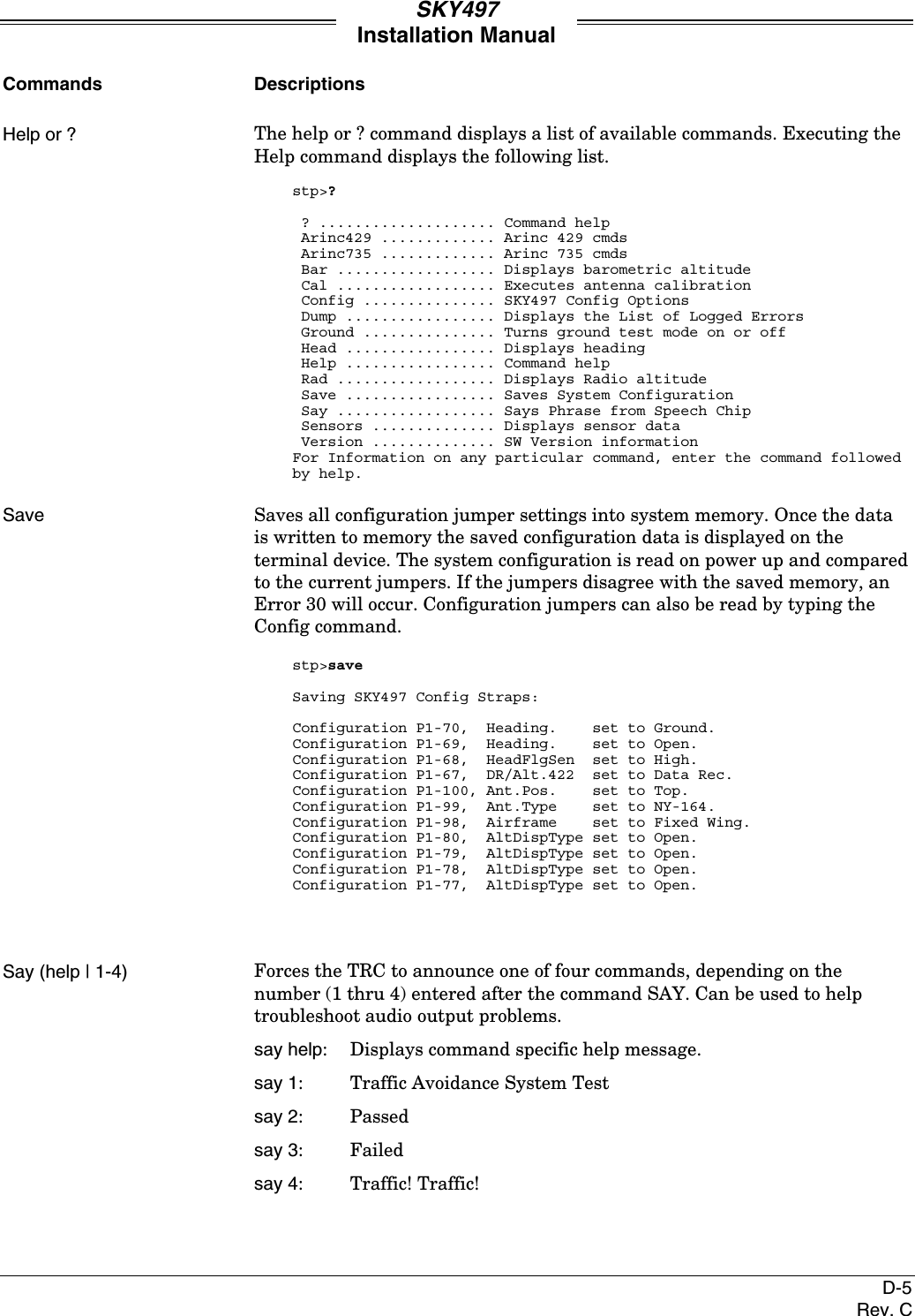
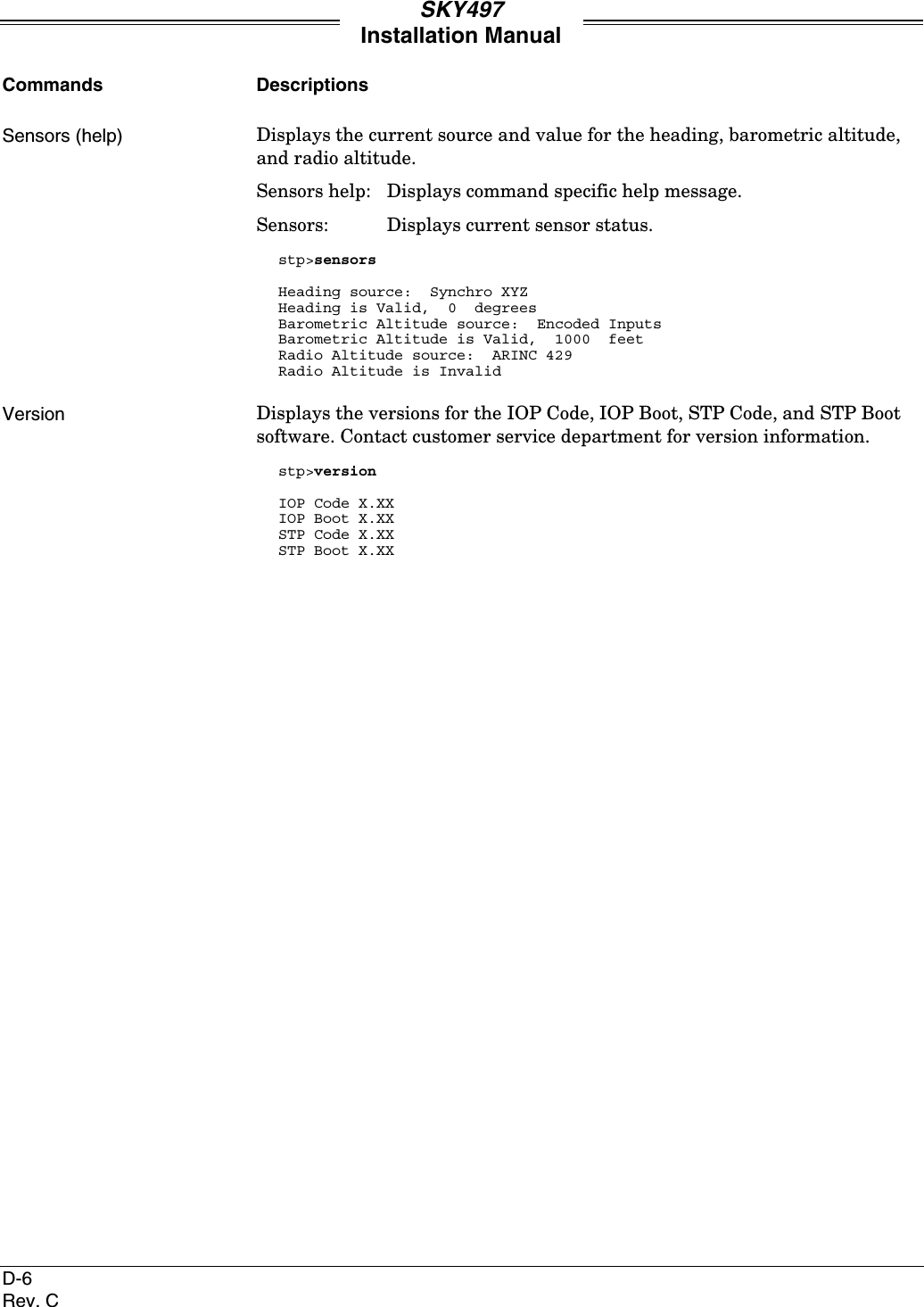
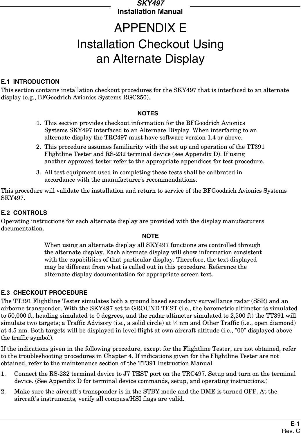
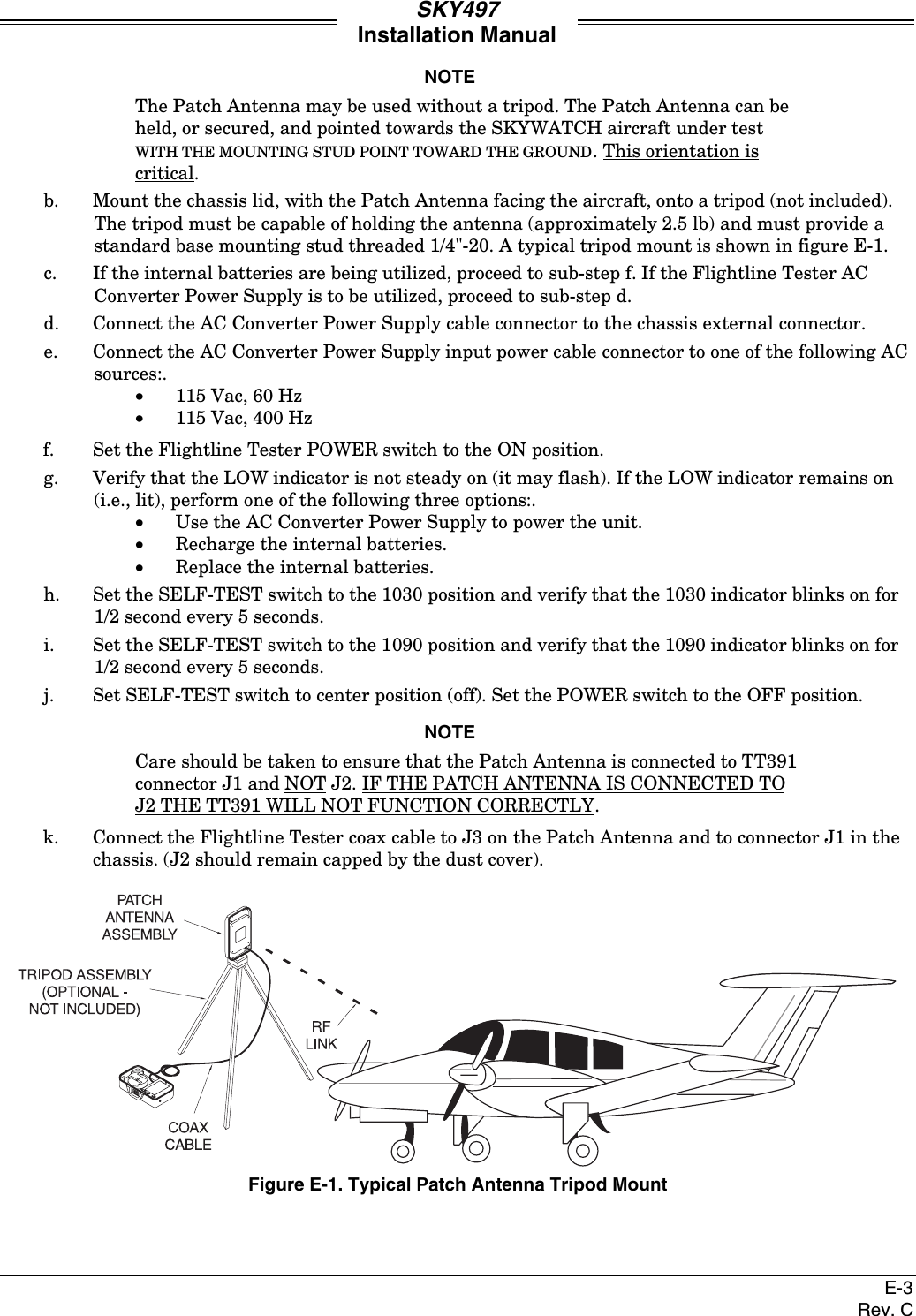
Install Manual part 3 of 3