LG Electronics USA 9QK-DMR3 Wireless Adapter Card User Manual NAM WM1S Manual ENGx
LG Electronics USA Wireless Adapter Card NAM WM1S Manual ENGx
UserManual.wiki
>
LG Electronics USA
>
9QK DMR3 User Manual
User Manual
Navigation menu
Upload a User Manual
Namespaces
Wiki Guide
HTML
PDF
Info
Views
User Manual
Discussion / Help
Navigation
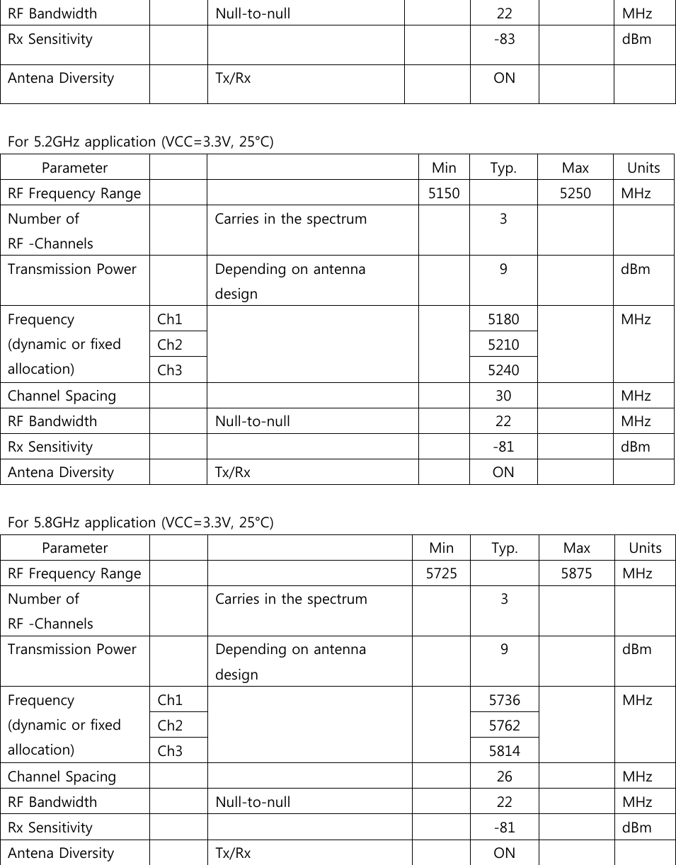
![Connect the USB one by one and select each unique USB port setting for each evaluation board. 1) Click the [Refresh] button. 2) Select the EVK ID, for example “A3UNG243”, to access the 4ch EVK connected to the DWAM83 module. 3) Click the [Apply] button. 4) (Optional) If the “A3UNG243”option cannot be selected from the drop down menu, click the [Disconnect] button before repeating steps 1 ~ 3. Once the connection is successful, you should see READY in Module Status. . If you see NOT FOUND, please check that the USB cable is properly connected/loose or 5V DC Power is plugged in. Step 6: At the top-left corner of the GUI, click Help and click About. The current firmware version is shown as Evaluation Kit Version X.X.X. The current GUI version is shown as Configuration Software GUI Version X.X.X. 2 1 3 4](https://usermanual.wiki/LG-Electronics-USA/9QK-DMR3/User-Guide-1958746-Page-4.png)
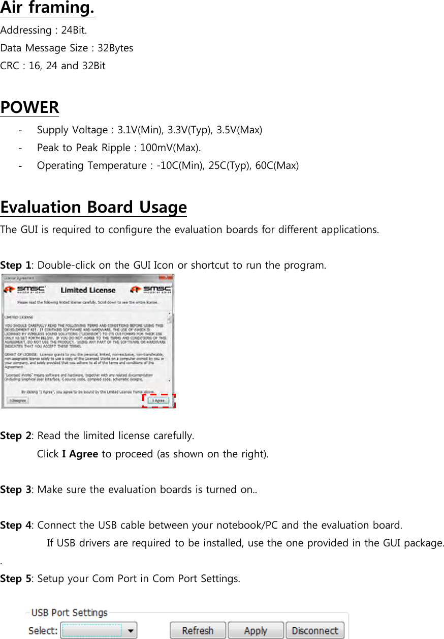
![Step 7: Setup your choice of application in the Application Selection (Power-up Settings) For the explanation for the different kinds of application, you can check the help file that is provided with the Evaluation board (EVK). Step 8: Click [Config] button (upon every change) to configure the evaluation board. Select desired application (depending on the number of Stereo sources required) Press this button whenever there are any changes in this section to update the module settings Select the Frequency band (2.4GHz or 5.2GHz or 5.8GHz) to operate after Configuration Select CU or MU mode](https://usermanual.wiki/LG-Electronics-USA/9QK-DMR3/User-Guide-1958746-Page-5.png)