Landis Gyr Technology CONCS4 Series-4 Conc. User Manual 10 0097 Exhibit Cover
Landis+Gyr Technology, Inc. Series-4 Conc. 10 0097 Exhibit Cover
UserManual.wiki
>
Landis Gyr Technology
>
CONCS4 User Manual
Manual
Navigation menu
Upload a User Manual
Namespaces
Wiki Guide
HTML
PDF
Info
Views
User Manual
Discussion / Help
Navigation
![Limitation on Warranties and LiabilityInformation in this document is subject to change without notice. This manual or any part of it thereof may not be reproduced in any form unless permitted by contract or by written permission of Landis+Gyr.In no event will Landis+Gyr be liable for any incidental, indirect, special, or consequential damages (including lost profits) arising out of or relating to this publication or the information contained in it, even if Landis+Gyr has been advised, knew, or should have known of the possibility of such damages.© 2010 Landis+Gyr, Inc. All Rights Reserved.TrademarksWanGate®, Cellnet®, Gridstream®, and RadioShop® are registered trademarks of Landis+Gyr.Other brands or product names are the trademarks or registered trademarks of their respective holders.Gridstream Phase IV Concentrator User and Installation GuidePublication: 98-1031 Rev AARevision HistoryModification Date Revision Description Author6/28/10 AA Released Randy RotenLandis+Gyr30000 Mill Creek AvenueSuite 100Alpharetta, GA 30022Website: www.landisgyr.comE-mail: ëçäìíáçåëìééçêíKå~]ä~åÇáëÖóêKÅçãTechnical Support: 1-888-390-5733Copyright© 2010 Landis+Gyr, Inc.All rights reserved.](https://usermanual.wiki/Landis-Gyr-Technology/CONCS4/User-Guide-1304127-Page-3.png)
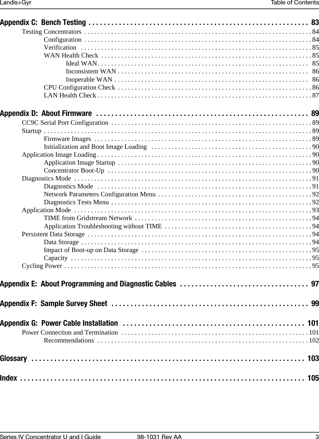
![Landis+Gyr Chapter 1 - PrefaceSeries IV Concentrator U and I Guide 98-1031 Rev AA 7Contacting Technical SupportWithin the United States, Landis+Gyr technical support is available by telephone or email. When you contact technical support, be prepared to give exact descriptions of:• The problem you encountered• What happened and what you were doing when the problem occurred• How you tried to solve the problem• The exact text of any error messagesTelephone AccessGridstream Technical support is available 24/7 by calling 1-888-390-5733. If all support technicians are helping other customers, your call will be routed to the Landis+Gyr Support voice mail system.Leave a brief message that includes the following information:• Your name• Your company’s name• Your telephone numberA support technician will return your call as soon as possible within normal business hours. Technicians return all calls in the order that they are received.Email AccessIf you prefer, you may email a description of your problem to:ëçäìíáçåëìééçêíKå~]ä~åÇáëÖóêKÅçãA support technician will return your email as soon as possible within normal business hours. Technicians return all emails in the order that they are received.](https://usermanual.wiki/Landis-Gyr-Technology/CONCS4/User-Guide-1304127-Page-10.png)
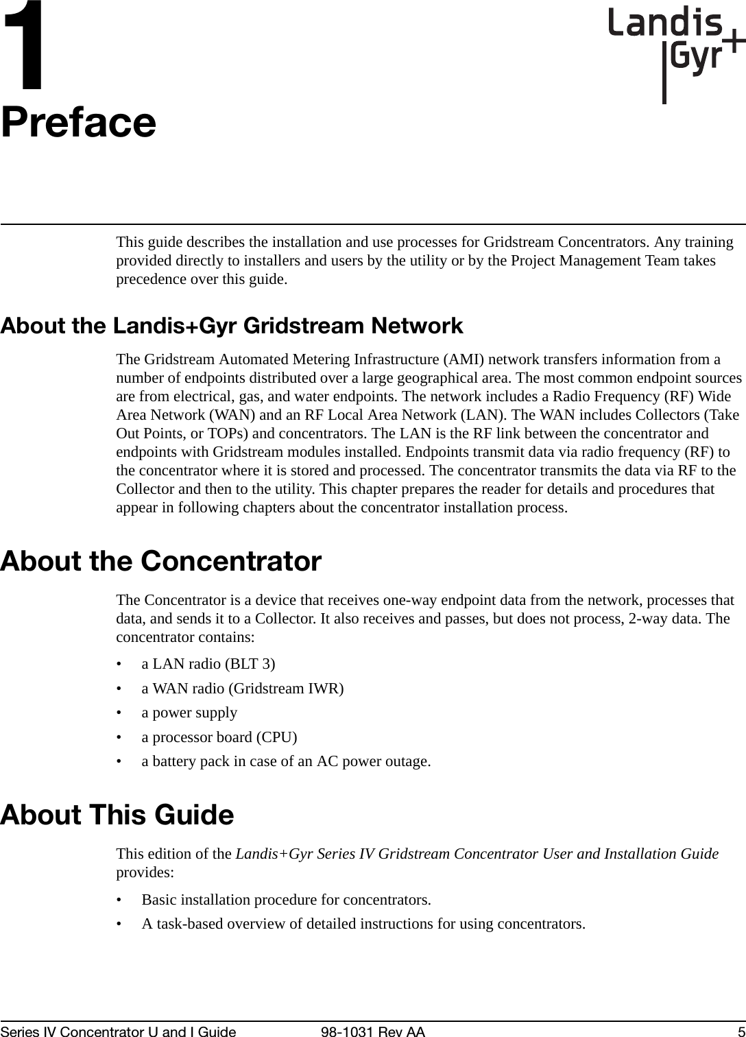
![Chapter 1 - Preface Landis+Gyr8 98-1031 Rev AA Series IV Concentrator U and I GuideGeneral InquiriesYour feedback is important in helping to provide accurate and high-quality information. If you want to reach a Landis+Gyr sales representative, or for other inquires, do one of the following:• Voice: 678-258-1500• Fax: 678-258-1550You can also mail your comments or inquires to:Landis+Gyr30000 Mill Creek AvenueSuite 100Alpharetta, GA 30022Ordering PublicationsYou can order publications from your sales representative. To order additional copies of this manual, use order number:98‐1031RevAAPublication CommentsIf you have suggestions for improving this publication, Landis+Gyr welcomes your feedback and recommendations. Landis+Gyr accepts comments via email, conventional mail, or fax.If you would like a reply, please include your contact information:•Name• Telephone number or fax number• Email address• Company name and addressBe sure to include the following information along with your comment:• Title and number of this manual (Landis+Gyr Gridstream Series IV Concentrator User and Installation GuideRevAA)• Page number or topic related to your commentLandis+Gyr reserves the right to use or distribute whatever information you supply in any way we believe appropriate without incurring any obligation to you.To send your comments via...Use this contact information...bã~áä ëçäìíáçåëìééçêíKå~]ä~åÇáëÖóêKÅçã`çåîÉåíáçå~ä=ã~áä i~åÇáëHdóêI=PMMMM=jáää=`êÉÉâ=^îÉKI=pìáíÉ=NMMI=^äéÜ~êÉíí~I=d^=PMMOOc~ñ ESTUF=ORUJNRRM](https://usermanual.wiki/Landis-Gyr-Technology/CONCS4/User-Guide-1304127-Page-11.png)
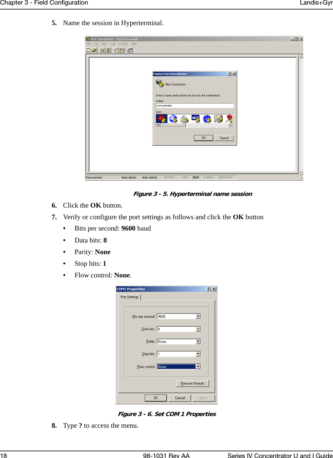
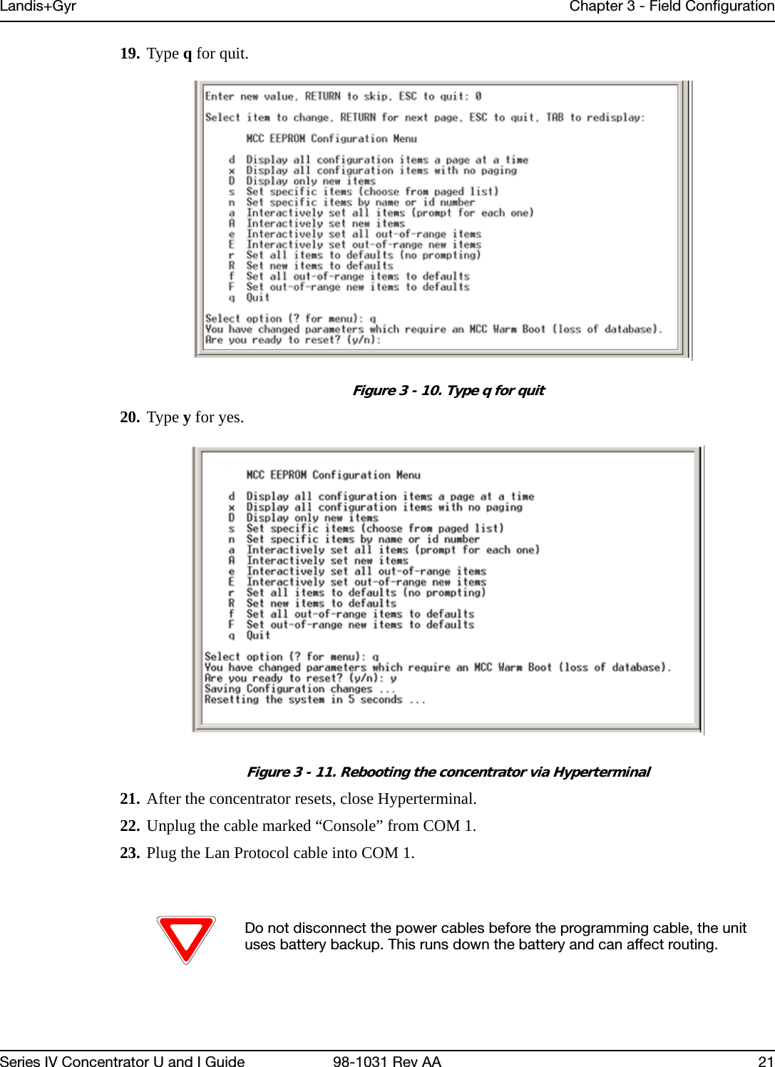
![Landis+Gyr Chapter 3 - Field ConfigurationSeries IV Concentrator U and I Guide 98-1031 Rev AA 199. Type c for configuration.Figure 3 - 7. Type c for configuration10. Type s for set specific items.Figure 3 - 8. Type s to set specific items11. Reset values by typing the letter in Hyperterminal corresponding to the item, then updating the value. For more information, see Sample Survey Sheet. Update the following items:A. [d]*Gateway MCC DMS Net Address [1..4294967039;default=4294967038]: 100051 Input the assigned Concentrator ID here.B. [e]*Gateway MCC DMS node address (normally 1)C. [1..65534;default=65534]: 1 This value is always 1.D. [f]+Log manager's (and CTS's) DMS Net Address [1..4294967039;default=4294967039]: 20 Input the assigned Net ID.](https://usermanual.wiki/Landis-Gyr-Technology/CONCS4/User-Guide-1304127-Page-22.png)
![Chapter 3 - Field Configuration Landis+Gyr20 98-1031 Rev AA Series IV Concentrator U and I GuideE. [g]+Log manager's (and CTS's) DMS node address [1..65534;default=65534]: 152 Input the assigned Node ID.F. [h]+Event manager's DMS Net Address [1..4294967039;default=4294967039]: 20 Input the assigned Net ID again.G. [i]+Event manager's DMS node address [1..65534;default=65534]: 152 Input the assigned Node ID again.H. [m]*Minutes from GMT (0=GMT, 480=PST) [positive increments of 60] [-720..720;default=480]: 420 Input the minutes from GMT.I. [n]*Daylight savings type (0=none, 1=USA, 7=UK) [0..7;default=1]: 1 This value is always 1.12. After you change the value, press the TAB key to refresh the page.13. Press the Enter key to go to the next page. 14. Update the following field:A. [e]+Lan Tx address for this MCC (0 = no Tx) [default=0]: 0 Always start with the number 400 (unless the concentrator address is 5 digits, then start with 4000), then append the concentrator ID. For example, if the concentrator ID is 100016, then the Lan Tx address is 400100016.15. Press the Enter key until you see a list of Network Filter configuration items..Figure 3 - 9. Type 0 for disable16. Type the letter J for Network Filter: Disable/Enable option.17. Type 0 to disable network filtering, and then press [Enter] 18. Press the Escape key.](https://usermanual.wiki/Landis-Gyr-Technology/CONCS4/User-Guide-1304127-Page-23.png)
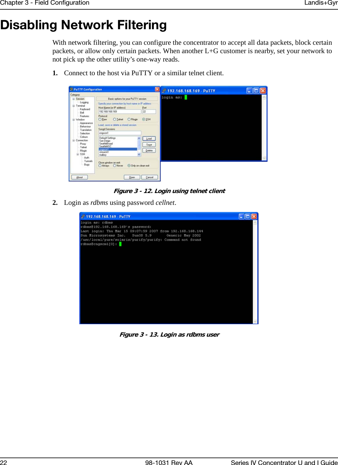
![Landis+Gyr Chapter 3 - Field ConfigurationSeries IV Concentrator U and I Guide 98-1031 Rev AA 233. Use the command rcautil xxxx 1 to log into the concentrator with ID <xxxx>.Example: rcautil 5002 1 Figure 3 - 14. Login to concentrator4. After the screen displays “Remote console device CONNECTED”, press [Enter]. Figure 3 - 15. Open console menu remotely5. Type the letter c. The EEPROM configuration menu displays. Figure 3 - 16. EEPROM Menu](https://usermanual.wiki/Landis-Gyr-Technology/CONCS4/User-Guide-1304127-Page-26.png)
![Chapter 3 - Field Configuration Landis+Gyr24 98-1031 Rev AA Series IV Concentrator U and I Guide6. Type the letter n. The system prompts for a name. Figure 3 - 17. Name prompt7. Type 81 to access the network filtering menu and press [Enter]. Figure 3 - 18. Type 818. The default network filtering value is 1.To disable network filtering, type 0 and press [Enter] Figure 3 - 19. Network Filtering value](https://usermanual.wiki/Landis-Gyr-Technology/CONCS4/User-Guide-1304127-Page-27.png)
![Landis+Gyr Chapter 3 - Field ConfigurationSeries IV Concentrator U and I Guide 98-1031 Rev AA 259. Type [ESC]. The EEPROM configuration menu re-displays.Figure 3 - 20. Return to EEPROM menu10. Type the letter q. The system prompts you to reset the concentrator.Figure 3 - 21. Are you ready to reset prompt11. To save changes, type y. The reset begins.Figure 3 - 22. Reset Process Displayed](https://usermanual.wiki/Landis-Gyr-Technology/CONCS4/User-Guide-1304127-Page-28.png)
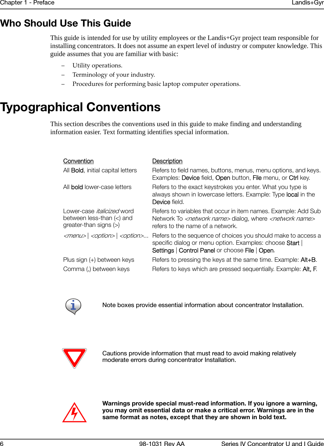
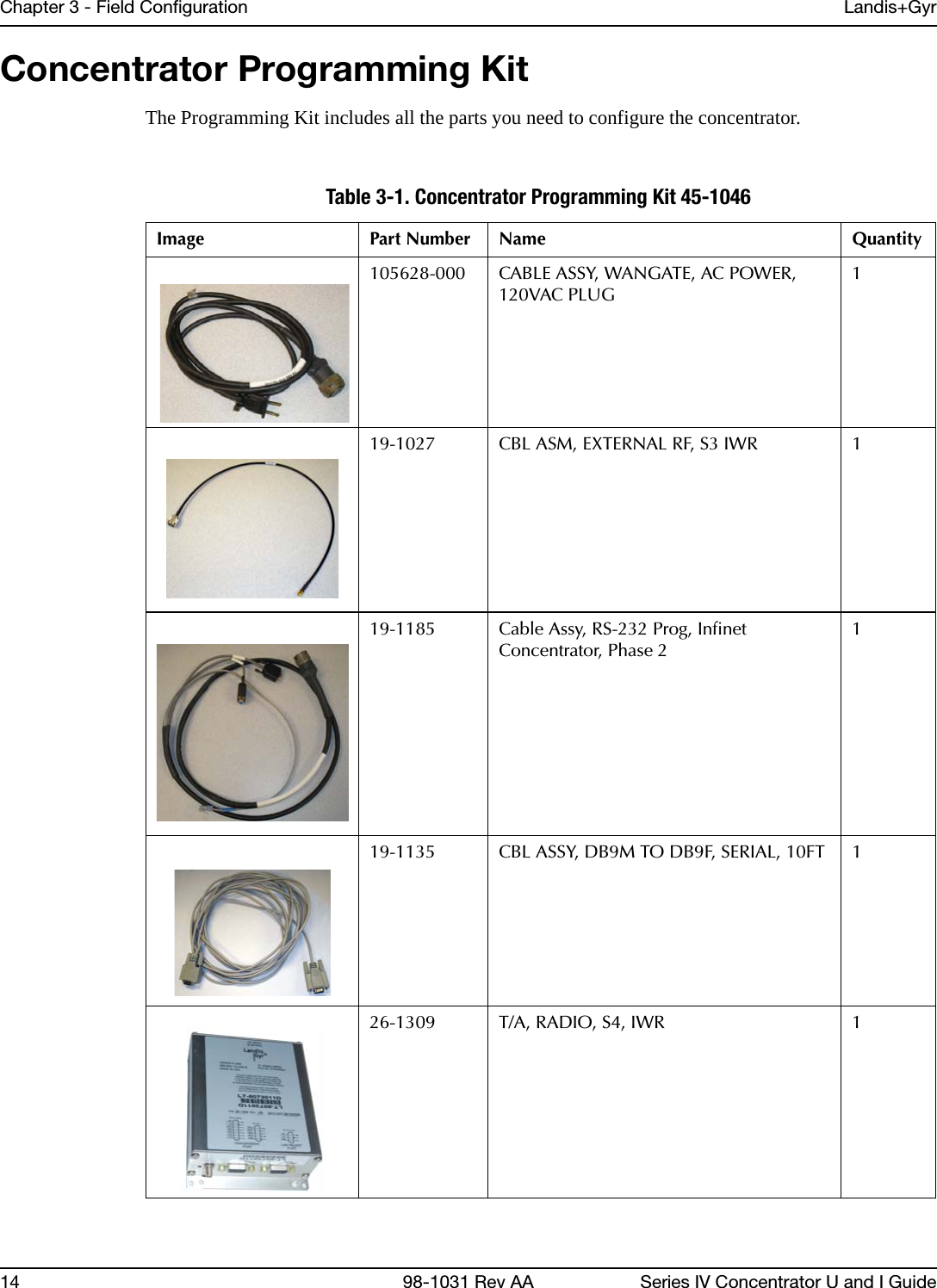
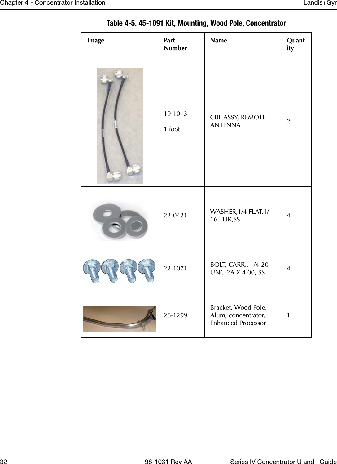
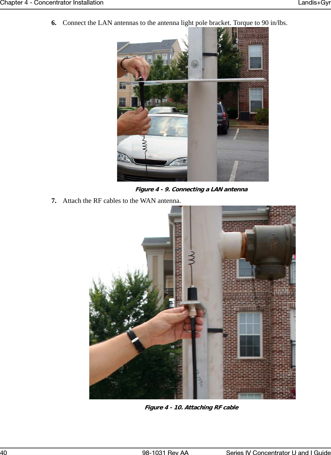
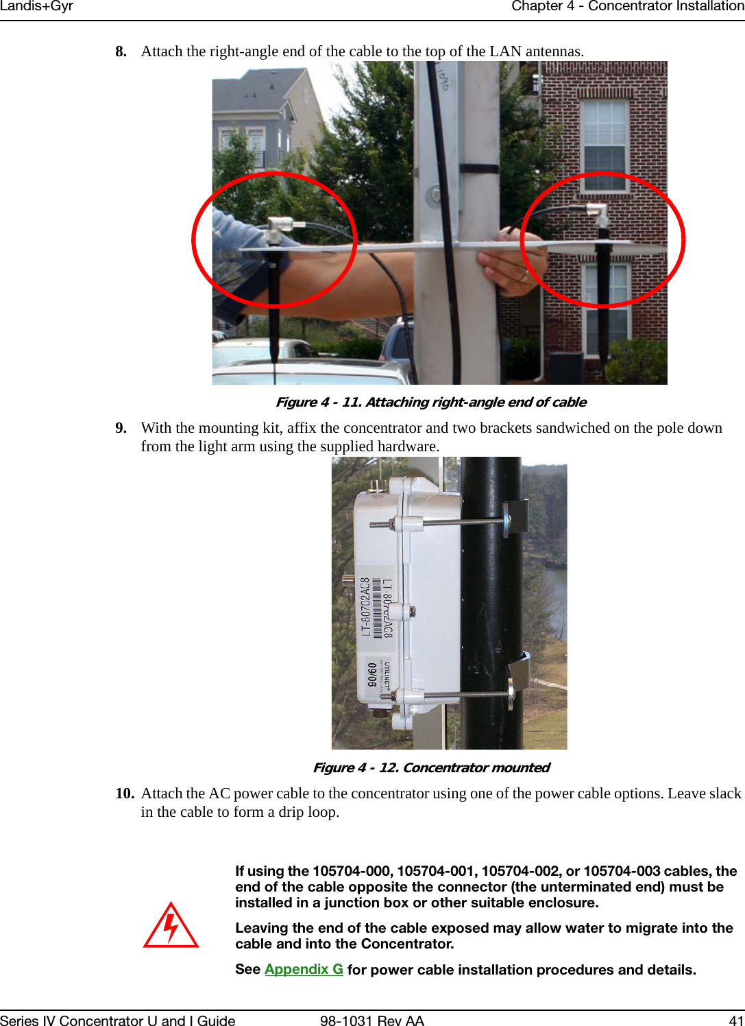
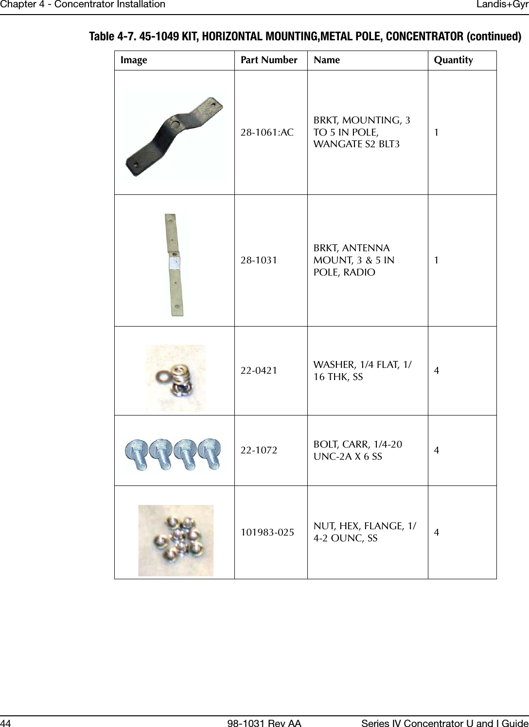
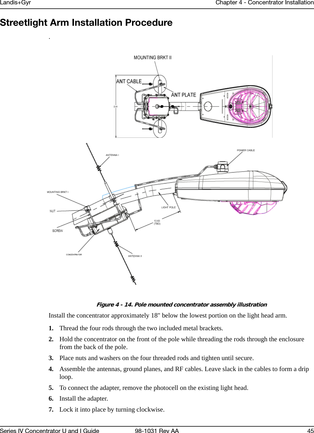
![Landis+Gyr Chapter 4 - Concentrator InstallationSeries IV Concentrator U and I Guide 98-1031 Rev AA 29Adding Drip Loops to CablesFor any cables in an assembly, allow some slack to rest below metal parts. The slack is called a “drip loop.” With a drip loop, water from rain and condensation drips from the cable without damaging associated mechanical equipment.Figure 4 - 1. Cable with drip loopKit Part NumbersDifferent kinds of installs may require different mounting and install kits. The following table contains a list of part numbers (PN) by install type. This document details each kit in the appropriate install description.For information about installation types not listed here, contact Landis+Gyr Customer Operations via ëçäìíáçåëìééçêíKå~]ä~åÇáëÖóêKÅçã.Table 4-2. Mounting and Programming KitsKit Number Wood Pole Install Light Pole Horizontal Mount InstallMetal Pole Vertical Mount Install Mounting KitPN 45-1091 xMounting KitPN 45-1050, 8” rodx Mounting KitPN: 45-1049 xMounting KitPN: 45-1055, 12” rodxProgramming KitPN 45-1046 xxx](https://usermanual.wiki/Landis-Gyr-Technology/CONCS4/User-Guide-1304127-Page-32.png)

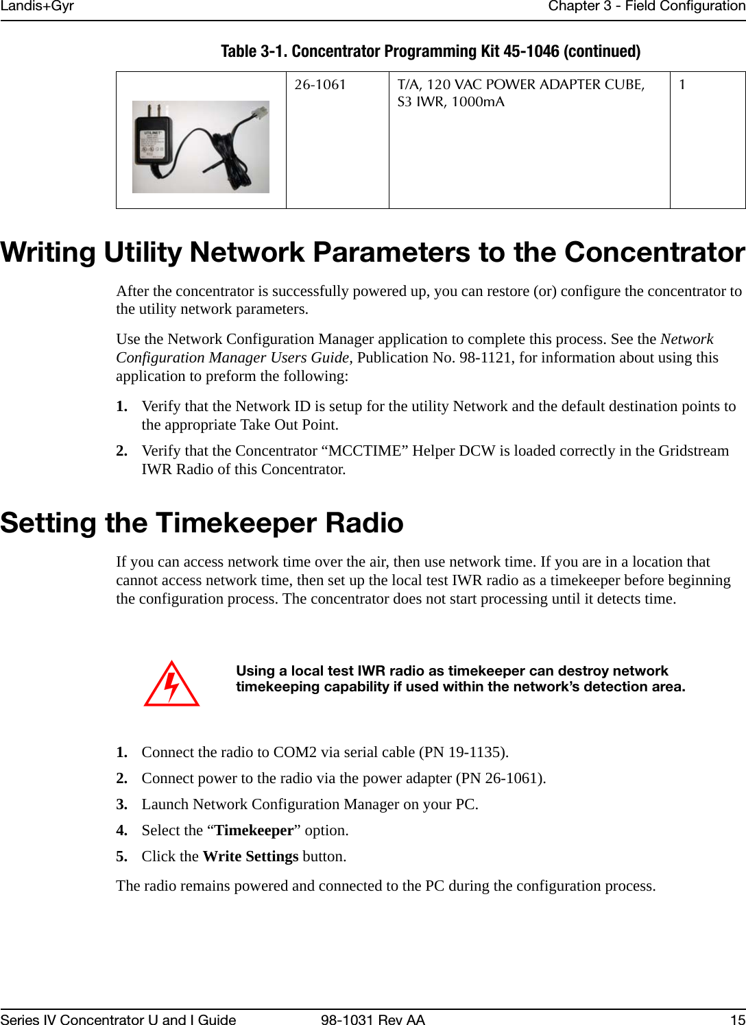
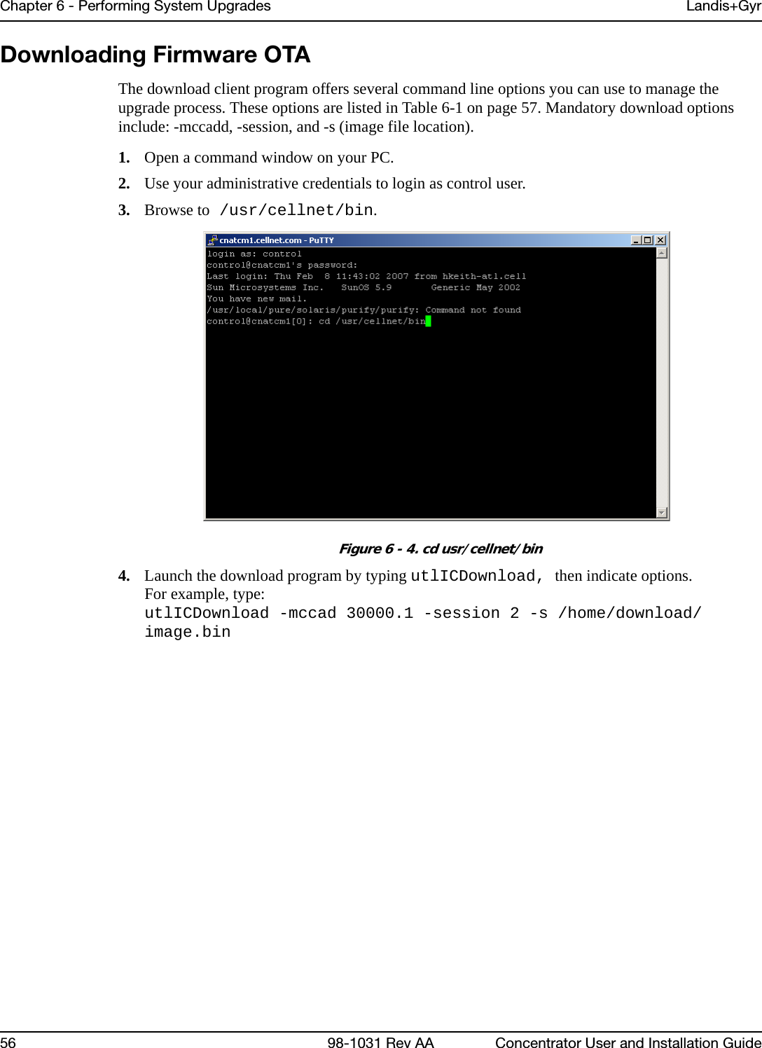
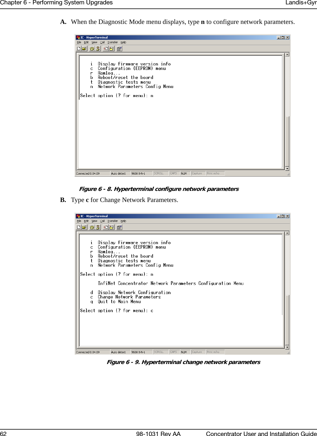
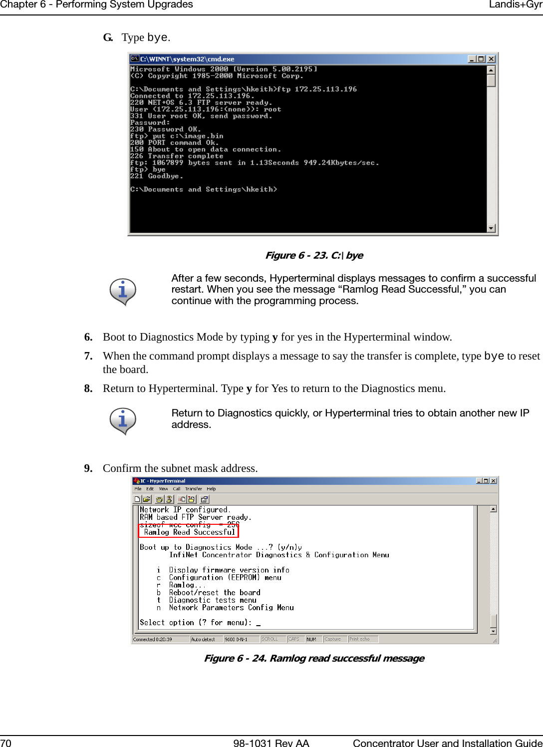
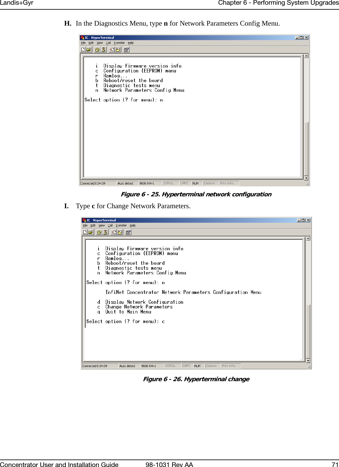
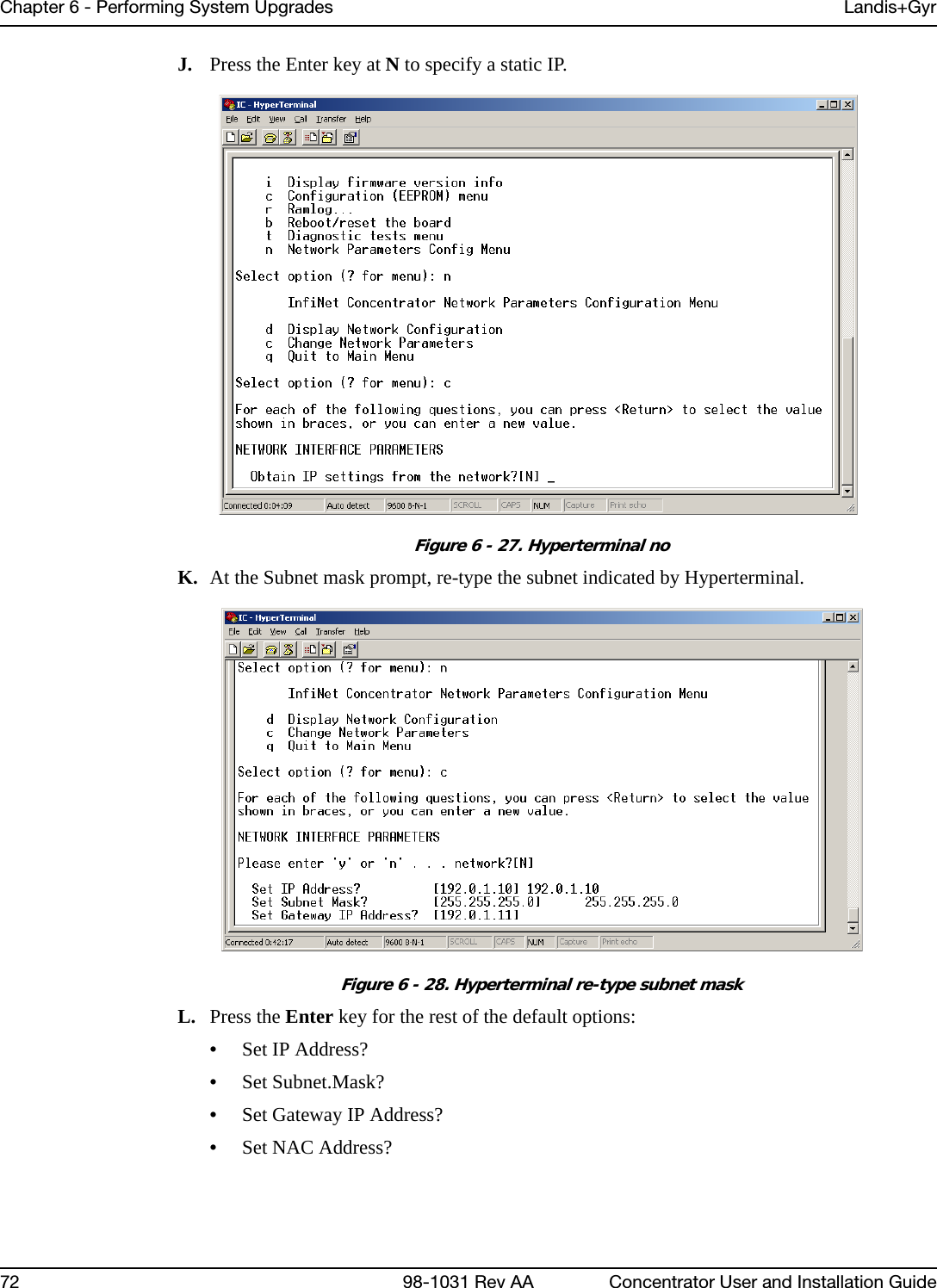
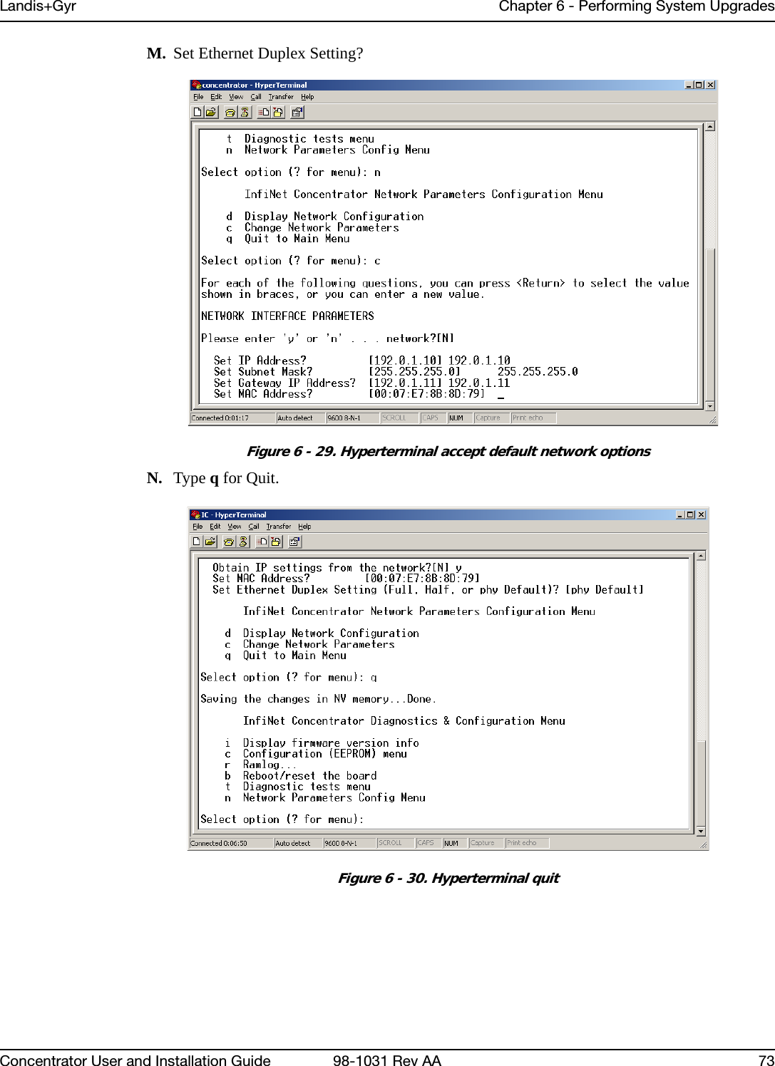
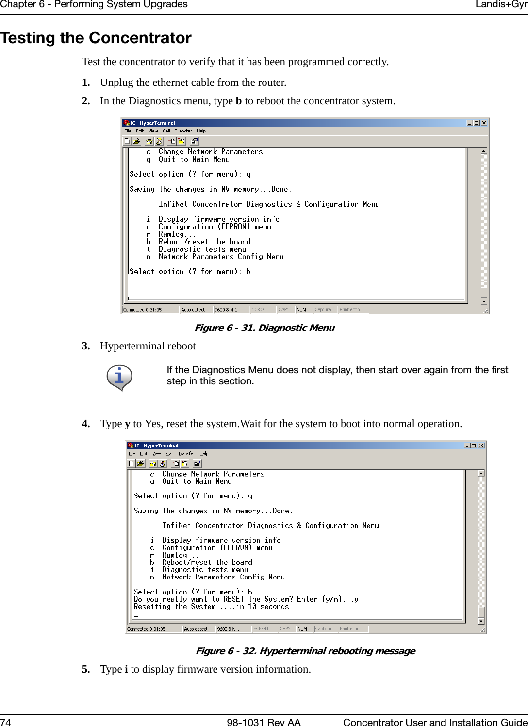
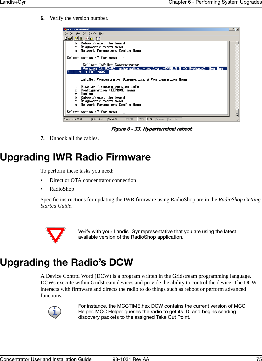
![6Concentrator User and Installation Guide 98-1031 Rev AA 53Performing System UpgradesWhat Are System Upgrades?There are three kinds of upgrades you can perform on a concentrator:• The concentrator firmware• The IWR radio firmware• The IWR radio DCW.Accessing a Concentrator for ProgrammingThere are two ways to access a concentrator for upgrading:•Over the air• Directly via cable (About Programming and Diagnostic Cables, for more information).Upgrading a Concentrator Over the Air (OTA)You can remotely download firmware to the concentrator via a command window from your PC. You must have control-level user access to the host to perform this procedure. About the Image FileLandis+Gyr Customer Operations manages upgrades to firmware. Landis+Gyr notifies you when there is a new release of firmware and makes the file available. To upgrade firmware, load the concentrator with a new “image.bin” file. Contact Customer Operations at ëçäìíáçåëìééçêíKå~]ä~åÇáëÖóêKÅçã for more information or to obtain the latest version of the firmware.The download application utility runs on the host backend via a process called Live System update (LSU). The host connects over the air (OTA) to the concentrator. The host automatically:1. Sends the new firmware information to the concentrator. 2. Polls the concentrator to verify that the download is complete. 3. Disconnects when the download is complete.](https://usermanual.wiki/Landis-Gyr-Technology/CONCS4/User-Guide-1304127-Page-56.png)
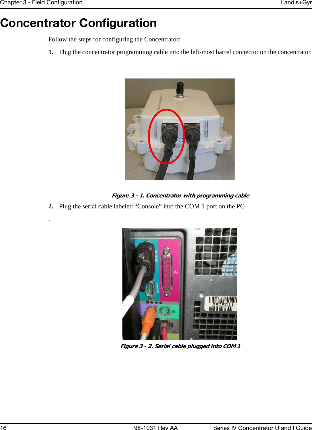
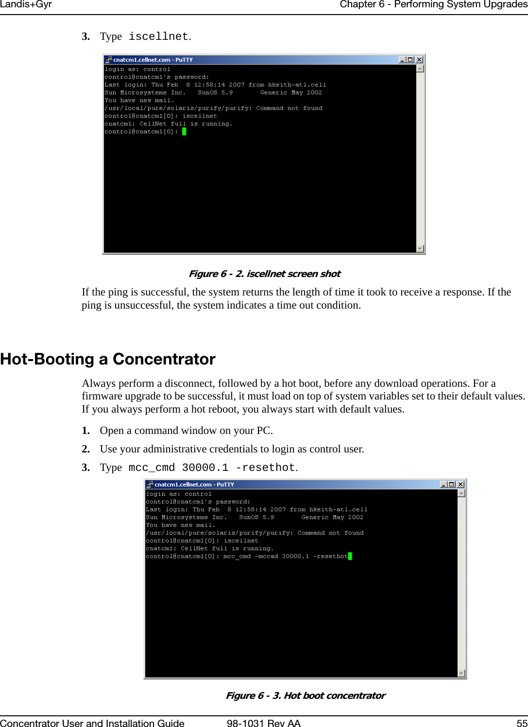
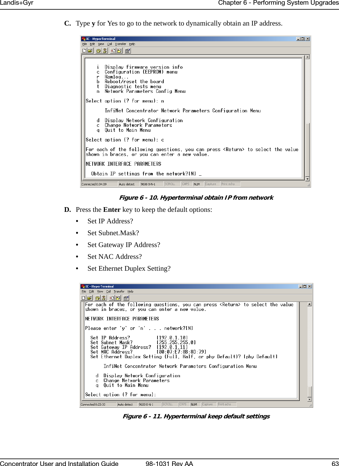
![Chapter 6 - Performing System Upgrades Landis+Gyr54 98-1031 Rev AA Concentrator User and Installation GuideVerifying the Concentrator and the HostBefore sending large amounts of data over the network, verify communication with the concentrator. Also verify that the Cellnet host is up and running. Ping the concentrator via command line rtrping.Pinging from the Command LineYou need to know the concentrator’s network ID before performing this task.1. Open a command window on your PC.2. Use your administrative credentials to login as control user.3. Type rtrping [concentrator ID].Figure 6 - 1. rtrping screen shotIf the ping is successful, the system returns the length of time it took to receive a response. If the ping is unsuccessful, the system indicates a time out condition.Verifying Host OperationsVerify that the Cellnet system is running.1. Open a command window on your PC.2. Use your administrative credentials to login as control user.Concentrator addresses used in the following instructions are samples only. Obtain your utility’s concentrator addresses from Customer Operations at ëçäìíáçåëìééçêíKå~]ä~åÇáëÖóêKÅçã.](https://usermanual.wiki/Landis-Gyr-Technology/CONCS4/User-Guide-1304127-Page-57.png)
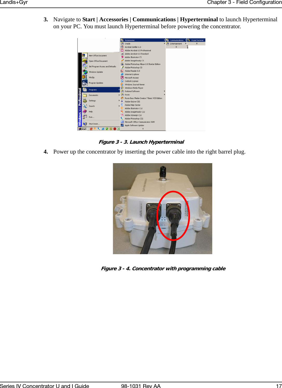
![Landis+Gyr Chapter 6 - Performing System UpgradesConcentrator User and Installation Guide 98-1031 Rev AA 57Figure 6 - 5. Launch OTA download programThe following table lists all the options in the download program: DownloadApplication Concentrator IDSession IDimage.bin filelocationsTable 6-1. Download Command Line SwitchesSwitch DescriptionMccad Mccad is the concentrator address <net>.<node> which requires a firmware upgrade.Example: utlICDownload -mccad 30000.1 [Args Reqd: 1 defaults: 0.0 format: %lu]Session Session is a number between 0 - 255. This is the session ID of the download task for the concentrator. All operations for the download have the same session number.Example: utlICDownload -session 5 [Args Reqd: 1 defaults: 2 format: %lu]-s CIF file The code image file (CIF) of the new version to be downloaded on the concentrator is usually present in the /home/download/MCC_Cnctr/ directory. If the directory does not exist, create one and place the image.bin file in that directory. Verify that it is the correct version. Downloading an older or incorrect version can cause loss of communication with the concentrator.Example: utlICDownload -s /home/download/MCCCTR/image.bin [Args Reqd: 1 defaults: 2 format: %s]](https://usermanual.wiki/Landis-Gyr-Technology/CONCS4/User-Guide-1304127-Page-60.png)
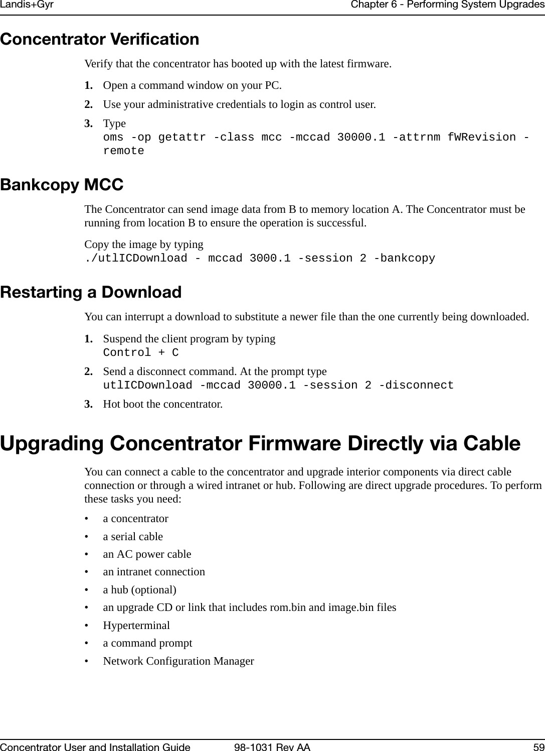
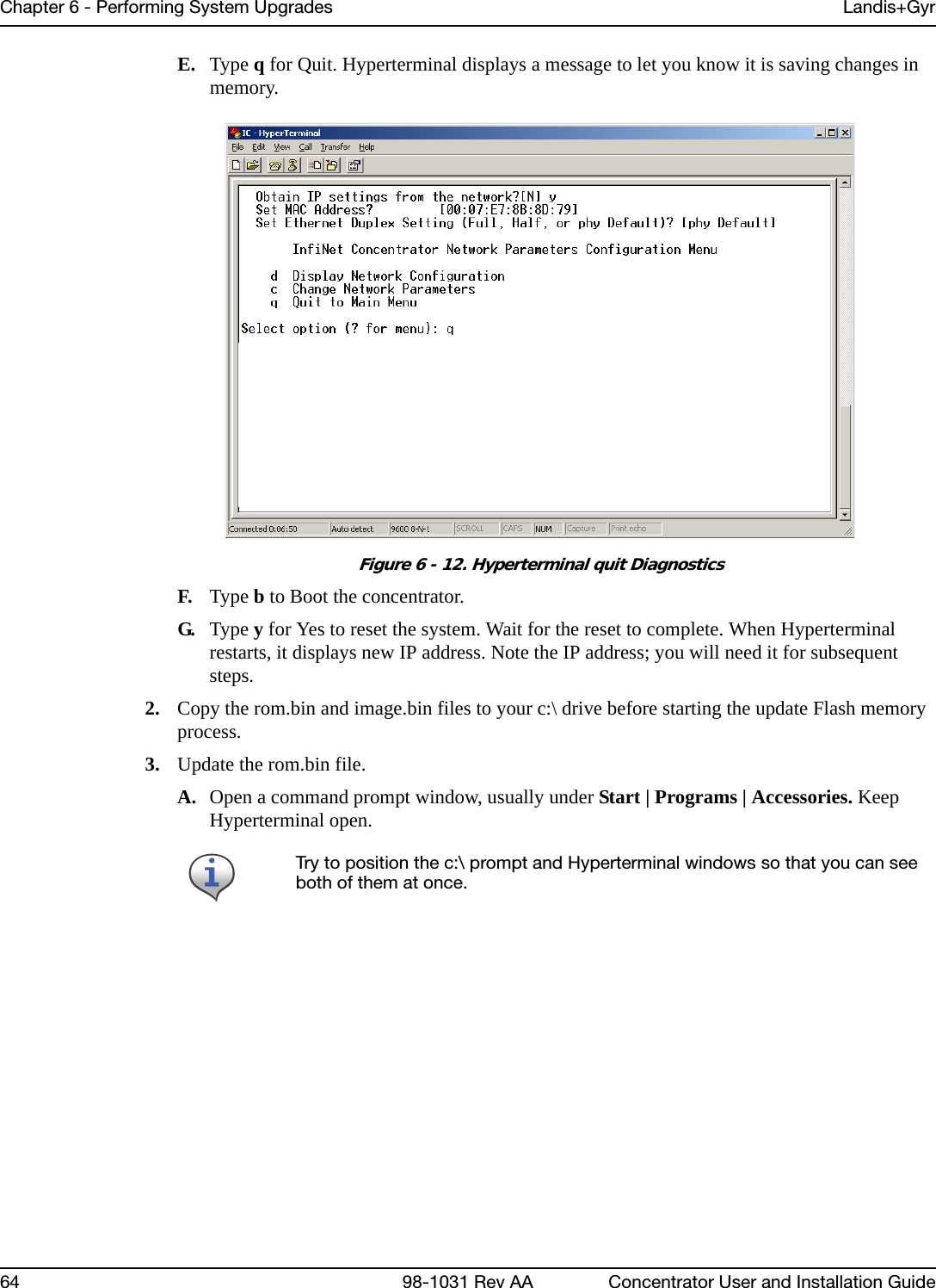
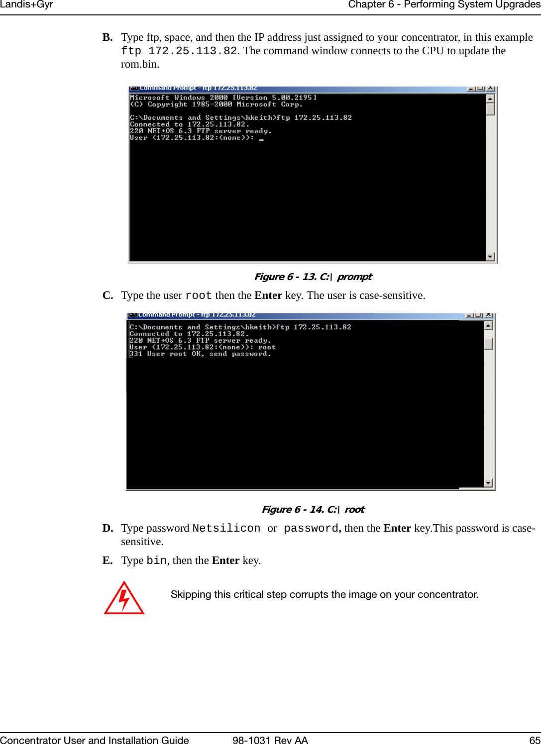
![Chapter 6 - Performing System Upgrades Landis+Gyr58 98-1031 Rev AA Concentrator User and Installation GuideSwitchover ConcentratorAfter the download is complete, login to the concentrator to instruct it to switchover. 1. Open a command window on your PC.2. Use your administrative credentials to login as control user.3. Type ./utlICDownload -mccad 30000.1 -session 2 -switchover-disconnect You need the disconnect session ID if the earlier download was terminated before completion. In this case, you must enter all the options of the download command and include the disconnect session ID. That should be the same session number that was terminated earlier.Example: utlICDownload -disconnect 5-nohotboot Override automatic disconnect and hotboot to avoid hot booting the MC be fore the session. In this case, you must start run disconnect and hotboot.Example: utlICDownload -nohotboot -session 5 -mccad 30000.1 -s <filename>-waittime Time to wait (in seconds) before sending the next packet. The download firmware process sends a total of nine packets. The waittime option allows for a delay between packets sent.Example: utlICDownload -waittime 4/MCCCTR/image.bin [Args Reqd: 1 defaults: 2 format: %s]-bankcopy Copy Concentrator image from B to A. The Concentrator must be running the image from B.This option applies to versions 14.02.06 and greater. Example: utlICDownload -mccad 30000.1 -bankcopy-debugprint Dump raw hex.Example: utlICDownload -debugprint [Args Reqd: 1 defaults: 2 format: %s]-help Print help information.Example: utlICDownload -help-query Get status of concentrator.Example: utlICDownload -query-switchover Switchover concentrator.Example: utlICDownload -switchoverTable 6-1. Download Command Line Switches (continued)Switch DescriptionThe concentrator hot boots after this step.](https://usermanual.wiki/Landis-Gyr-Technology/CONCS4/User-Guide-1304127-Page-61.png)
![Chapter 6 - Performing System Upgrades Landis+Gyr76 98-1031 Rev AA Concentrator User and Installation GuideUpgrade the concentrator’s DCW with Network Configuration Manager tool, via direct or OTA connection. 1. Open the Network Configuration Manager tool.2. Connect to the concentrator’s radio.3. Click the Load DCW button.4. Select the DCW from the file list.5. Click the Open button.6. The DCW loads and a series of messages display along the status bar of the Network Configuration Manager window.7. Network Configuration Manager displays a message when the DCW loads successfully. For more information about working with DCWs, see the Network Configuration Manager Users Guide.The MCC Helper DCW displays in the DCW section of the window. Verify with customer support at ëçäìíáçåëìééçêíKå~]ä~åÇáëÖóêKÅçã that you have the most current version.](https://usermanual.wiki/Landis-Gyr-Technology/CONCS4/User-Guide-1304127-Page-79.png)
![7Series IV Concentrator U and I Guide 98-1031 Rev AA 77TroubleshootingThis chapter lists common issues and steps to take to solve related problems. Contact Landis+Gyr Customer Operations at ëçäìíáçåëìééçêíKå~]ä~åÇáëÖóêKÅçã with questions.Verifying ConfigurationIf the network does not discover a concentrator, verify that the correct Network ID and destination are programmed into the radio. If so, then verify that the radio can communicate with the TOP. To verify communications with the TOP, use the ping command in the Network Configuration Manager application. This sends a message to the TOP and back to verify the TOP exists. Ping while plugged directly into the concentrator via a cable or over the air via another radio from the ground that is connected to the concentrator. • If the ping is not successful, double-check the destination or choose another TOP. • If the ping is successful, ensure that the radio is able to read the MCCID in the CPU. To check the CPU, connect to the radio, and then locate the MCCID (in format MCC Helper v1.16a (130603) from the DCW list on the Network Configuration Manager main screen, as shown in Figure 7 - 1. Figure 7 - 1. MCCIDThe Network Configuration Manager application is required to perform these steps.](https://usermanual.wiki/Landis-Gyr-Technology/CONCS4/User-Guide-1304127-Page-80.png)
![Chapter 7 - Troubleshooting Landis+Gyr78 98-1031 Rev AA Series IV Concentrator U and I GuideIf the MCCID is zero (in format MCC Helper v1.16a (0) from 4F.91.E6.20.92.1F [FE.FF.00.A7]), a CPU configuration failure occurred and the DCW was unable to communicate with the CPU. To configure the CPU so it can communicate with the DCW, complete the following steps:1. Connect to the CPU using Hyperterm, and then select Y in the Boot screen to boot the unit into diagnostic mode.2. Type C.The EEPROM Configuration menu is displayed for you to verify information.3. Verify or edit the programmed values for:•MccNetAddress•MccNodeAddress•LogMgrNetAdddress•LogMgrNodeAddress•AlarmNetAddress•AlarmNodeAddress •MinutesFromGMT•DayLightSavingsTypeFollow the instructions and exit the EPROM menu, booting only if requested by the unit.](https://usermanual.wiki/Landis-Gyr-Technology/CONCS4/User-Guide-1304127-Page-81.png)
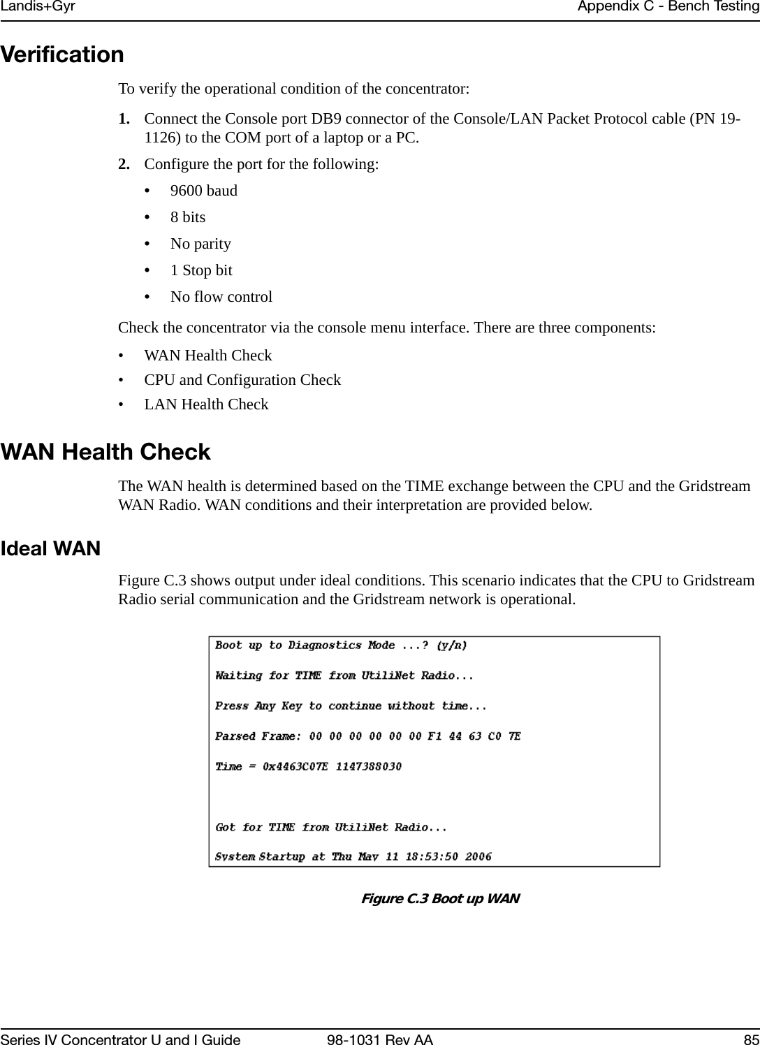
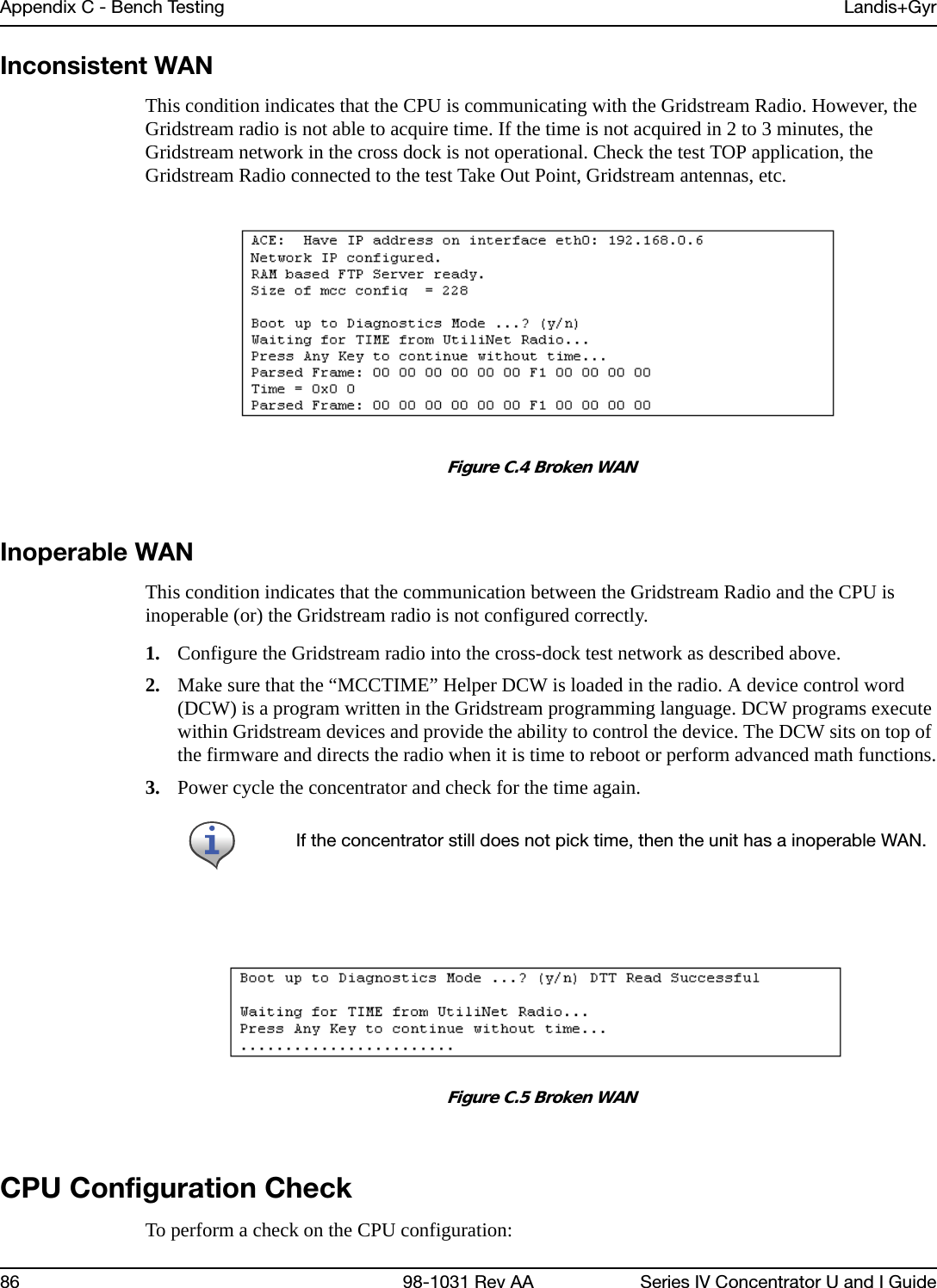
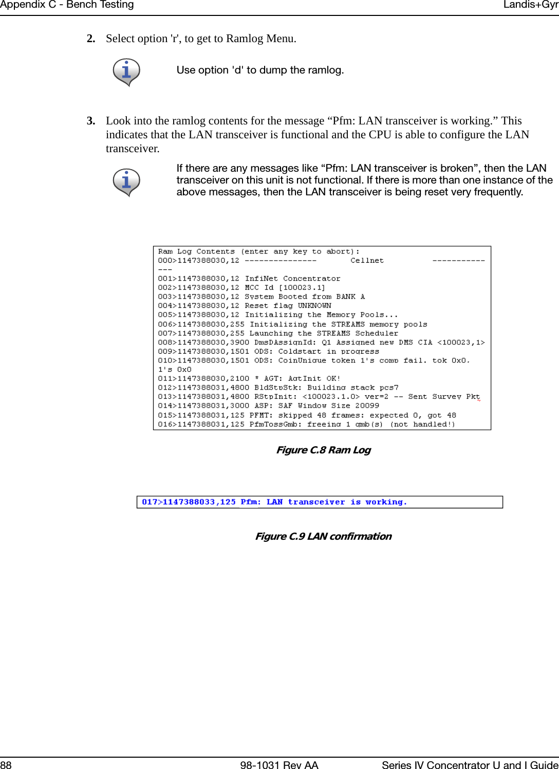
![Landis+Gyr Appendix C - Bench TestingSeries IV Concentrator U and I Guide 98-1031 Rev AA 871. From the Main Menu, go to the EEPROM configuration menu and verify the relevant EEPROM configuration parameters. 2. From the concentrator EEPROM Configuration Menu display the configuration. Scroll down the page that starts with “+Asap store&forward evt group size [0..65535;default=14]: 14". 3. Verify that the following highlighted parameters are set to 0.Figure C.6 CPU Configuration Check4. Scroll down to the page which starts with the configuration item “Gateway Concentrator Num of Cal objects stored in Flash [default=0]: 0".5. Verify that the following highlighted parameters are set to the values as shown below.Figure C.7 Concentrator ParametersLAN Health CheckThe LAN health is determined from the concentrator's RAMLOG. 1. From the Concentrator Main Menu select option 'd'. The Concentrator Debug Menu appears.](https://usermanual.wiki/Landis-Gyr-Technology/CONCS4/User-Guide-1304127-Page-90.png)