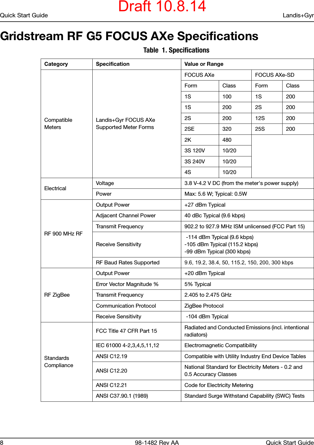
Landis Gyr Technology EG1R1S5 GridStream RF, G5 Focus AXe Module User Manual 14 0179 Exhibit Cover

Landis+Gyr Technology, Inc. GridStream RF, G5 Focus AXe Module 14 0179 Exhibit Cover

Manual

5015 B.U. Bowman Drive Buford, GA 30518 USA Voice: 770-831-8048 Fax: 770-831-8598Certification ExhibitFCC ID: R7PEG1R1S5IC: 5294A-EG1R1S5FCC Rule Part: 15.247IC Radio Standards Specification: RSS-210ACS Project Number: 14-0179Manufacturer: Landis+Gyr Technology, Inc.Model: G5 26-1905
Gridstream RFGeneration 5 (G5)FOCUS AXe EndpointQuick Start GuidePublication: 98-1482 Rev AADraft 10.8.14
Limitation on Warranties and LiabilityInformation in this document is subject to change without notice. This manual or any part of it thereof may not be re-produced in any form unless permitted by contract or by written permission of Landis+Gyr.In no event will Landis+Gyr be liable for any incidental, indirect, special, or consequential damages (including lost prof-its) arising out of or relating to this publication or the information contained in it, even if Landis+Gyr has been advised, knew, or should have known of the possibility of such damages.© 2014 Landis+Gyr, Inc. All Rights ReservedGridstream RF Generation 5 (G5) FOCUS AXe Endpoint Quick Start GuidePublication: 98-1482 Rev AARevision HistoryModification Date Revision Description Author10/08/2014 AA Pending Kim Utesch© 2014 Landis+Gyr • All rights reserved.Draft 10.8.14
Quick Start Guide 98-1482 Rev AA 3Gridstream RF Generation 5 (G5) FOCUS AXe EndpointQuick Start GuideGridstream RF Generation 5 (G5) FOCUS AXe Endpoint Figure 1. FOCUS AXe Meter with a G5 FOCUS AXe EndpointG5 FOCUS AXe Endpoint OverviewLandis+Gyr FOCUS AXe meters are designed for use in residential and light commercial services. The FOCUS AXe Advanced Function meter is an Active Energy kWh/kW/TOU Meter. The meter features Digital Multiplication Measurement Technique, meets ANSI standards for performance and utilizes ANSI C12.19 protocol.Draft 10.8.14
Quick Start Guide Landis+Gyr4 98-1482 Rev AA Quick Start GuideContact your Landis+Gyr distributors for documentation and details on programming the FOCUS AXe meter.About the LAN IDThe LAN ID is a unique identifier for each Landis+Gyr endpoint and it is always displayed in hex values. Landis+Gyr provides the LAN address. You cannot change the LAN ID of an endpoint.LabelsThe endpoint includes the following labels: Figure 2. Label IdentificationDemand (TOU Capable)•Peak demand•kWh, and kW demand (TOU capable)•Bi-directional measurement•Remote disconnect and reconnect capabilities on the FOCUS AXe Service Disconnect meter•Display and registers powered with disconnect switch in the open position•Detects, logs and reports program or memory failure•Module, ZigBee and Metrology firmware can be upgraded via the network•Metrology firmware can also be upgraded over the optical port•Normal operation during upgrades (displays blanks momentarily during F/W Flash)•Meter software remotely and locally readable•Remote or local load side voltage test•Self-reads occur at midnight for each register•Support for 12 self readsTOU/Recorder•8-channels of load profile•Interval data of 1, 5, 15, 30 and 60 minutes•Interval data collection for energy consumption•Meter distinguishes between missing interval and zero consumption•Meter distinguishes between power outage and zero consumption•5-minute interval data is available for a maximum of 45 days for two channelsDraft 10.8.14
Landis+Gyr Quick Start GuideQuick Start Guide 98-1482 Rev AA 5•Over-the-air-flashable firmware•Module, ZigBee and Metrology firmware can be upgraded via the networkMeter Configuration SupportConsult Landis+Gyr 1132COM/1132Prog documentation or contact your Landis+Gyr distributor for details on programming the Landis+Gyr meter.Net MeteringGridstream RF G5 FOCUS AXe endpoints also support the use of the Landis+Gyr meter for net metering usage in metrology values with 5-dial reads or greater. Net metering allows the endpoint to report the net power flow of energy in both directions when power is generated locally at a customer’s site (wind, solar, etc.). Figure 3. Enabling Net MeteringTime of Use (Battery-free)Landis+Gyr offers the capability of the endpoint to remotely control up to four TOU schedules. The Meter requires Network Time to keep TOU. The endpoint keeps time once acquired from the Network. The meter must be enabled for TOU.ZigBee/Home Area Network (HAN) FunctionalityWith the Gridstream RF G5 FOCUS AXe module, Landis+Gyr has the ZigBee radio platform for Gridstream RF which gives a utility the ability to increase consumer awareness of energy consumption and encourage personal responsibility for curbing the energy load. ZigBee released a Smart Energy Profile (SEP) application in early 2008 and it is quickly becoming a standard for communicating between energy management devices as part of a home area network (HAN).   The ZigBee radio is located on the Gridstream RF AXe module creating an Energy Service Interface (ESI) that manages the bi-directional communication with ZigBee radio-based devices such as in-home displays, smart thermostats and direct load control devices. See the figure below for a demonstration of the communication flow between Command Center and the devices in the home.Draft 10.8.14
Quick Start Guide Landis+Gyr6 98-1482 Rev AA Quick Start Guide Figure 4. ZigBee CommunicationUsing Command Center, the utility sets up the HAN remotely via RF network via a provisioning process. The utility registers each device and a security handshake occurs to ensure protected and closed communication between the meter, endpoint and energy devices in the home.The utility sends downstream pricing information and text messages via Command Center (or 3rd party integrated application) to the module, which uses the ZigBee radio to push down the information to the devices. Because the solution is bi-directional, the devices are also pulling meter data and accurate time that is maintained at the endpoint. The Gridstream RF G5 FOCUS AXe module refreshes data from the meter every 30 seconds and makes it available to all the devices. The endpoint makes available kWh values (delivered only) up to five dial resolution and instantaneous kW up to 99.999 for display. It supports up to five provisioned devices and makes available five tiers for pricing events to align with the meter's number of rates.Text messaging is limited to 80 characters.NOTE: ZigBee radio devices are consumer products and should not be considered part of a mandatory load control program, nor a replacement for viewing energy consumption with the same accuracy found on the meter display.   The utility will need to conduct some training of both internal personnel and consumers of the capabilities and limitations of HAN technology.ZigBee radio devices will need to be programmed to respond correctly to each pricing event or Time of Use rate from the meter. An in-home display like the ecoMeter, for instance, will request energy and instantaneous demand data every 7 seconds. It will also request price, which will be provided as flat or Time of Use (TOU) depending on how the meter is programmed. When it sees the meter has changed to Rate B, for instance, it may respond by changing the back lighting to indicate to the consumer that the price of energy has increased. Gridstream RF Network IndicatorThis feature provides a ‘communications health’ view of a Gridstream RF enabled electric metering endpoint on the LCD display of the meter. This health check information can be utilized during field installation or troubleshooting activities to validate status of the Gridstream RF electric endpoint, and provide key inputs to any communications issues that may be encountered from time to time.Draft 10.8.14
Landis+Gyr Quick Start GuideQuick Start Guide 98-1482 Rev AA 7The network indicator feature will display two key elements of communications health characteristics.•Communication Hardware Status: Information about AMI radio communications, HAN(ZigBee) radio communications, and the interactions between the two•RF Mesh Neighbor Status: Information about the number of RF mesh neighbors availablefor network communicationsFor more information on this feature see Appendix E: <Italics>"Gridstream RF Network Indicator" on page -109.Power Outage/RestorationWhen an outage occurs, the meter uses an early power failure signal to alert the communication module to disconnect from the meter's power immediately. The communication module saves critical module data to non-volatile memory and creates and sends a power outage message. This message includes the following information:•LAN ID•Outage time•Reboot countThe communication module sends the message, then assists with routing other packets until the back-up energy source can no longer keep the radio alive.When power is restored, the communication module connects with the network. With network communications restored, the communication module sends a power restoration message that includes details such as: •LAN ID•Outage time•Restoration time•Reboot countThe communication module stores a history of up to the last five power outage and restoration event pairs in the event log. The Host can request this data.NOTE: The module is designed with a high temperature protection feature in which the firmware automatically starts draining the super capacitor responsible for outage notification at 65 degrees Celsius.Standards ComplianceThe Gridstream RF G5 FOCUS AXe module has Smart Utility Network (SUN) 802.15 4G ready hardware.Flash Memory OptionsThe standard hardware configuration for the Gridstream RF G5 FOCUS AXe modules has 4MB flash memory. An 8MB flash memory option is also available.Draft 10.8.14
Quick Start Guide Landis+Gyr8 98-1482 Rev AA Quick Start GuideGridstream RF G5 FOCUS AXe Specifications Table  1. Specifications Category Specification Value or RangeCompatible MetersLandis+Gyr FOCUS AXe Supported Meter FormsFOCUS AXe FOCUS AXe-SDForm Class Form Class1S 100 1S 2001S 200 2S 2002S 200 12S 2002SE 320 25S 2002K 4803S 120V 10/203S 240V 10/204S 10/20ElectricalVoltage 3.8 V-4.2 V DC (from the meter's power supply) Power Max: 5.6 W; Typical: 0.5WRF 900 MHz RFOutput Power +27 dBm TypicalAdjacent Channel Power 40 dBc Typical (9.6 kbps)Transmit Frequency 902.2 to 927.9 MHz ISM unlicensed (FCC Part 15)Receive Sensitivity -114 dBm Typical (9.6 kbps)-105 dBm Typical (115.2 kbps)-99 dBm Typical (300 kbps)RF Baud Rates Supported 9.6, 19.2, 38.4, 50, 115.2, 150, 200, 300 kbpsRF ZigBeeOutput Power +20 dBm TypicalError Vector Magnitude % 5% TypicalTransmit Frequency 2.405 to 2.475 GHzCommunication Protocol ZigBee ProtocolReceive Sensitivity  -104 dBm TypicalStandards ComplianceFCC Title 47 CFR Part 15 Radiated and Conducted Emissions (incl. intentional radiators)IEC 61000 4-2,3,4,5,11,12 Electromagnetic CompatibilityANSI C12.19 Compatible with Utility Industry End Device TablesANSI C12.20 National Standard for Electricity Meters - 0.2 and 0.5 Accuracy ClassesANSI C12.21 Code for Electricity Metering ANSI C37.90.1 (1989) Standard Surge Withstand Capability (SWC) TestsDraft 10.8.14
Landis+Gyr Quick Start GuideQuick Start Guide 98-1482 Rev AA 9FCC and Industry Canada ComplianceFCC Class BThis device complies with Part 15 of the FCC rules. Operation is subject to the following two conditions: 1. This device may not cause harmful interference, and2. This device must accept any interference received, including interference that may causeundesired operation.This equipment has been tested and found to comply with the limits for a Class B digital device, pursuant to Part 15 of the FCC Rules. These limits are designed to provide reasonable protection against harmful interference in a residential installation. This equipment generates, uses, and can radiate radio frequency energy and, if not installed and used in accordance with the Instructions, may cause harmful interference to radio communications. However, there is no guarantee that interference will not occur in a particular installation. If this equipment does cause harmful interference to radio or television reception, which can be determined by turning the equipment off and on, the user is encouraged to try to correct the interference by one or more of the following measures: •Reorient or relocate the receiving antenna.•Increase the separation between the equipment and receiver.•Consult Landis+Gyr or an experienced radio technician for helpUWARNING: Changes or modifications to this device not expressly approved by Landis+Gyr could void the user’s authority to operate the equipment.RF ExposureThis equipment complies with FCC radiation exposure limits set forth for an uncontrolled environment. This equipment should be installed and operated with minimum distance 20 cm between the radiator and your body. This transmitter must not be co-located or operating in conjunction with any other antenna or transmitter.Industry CanadaThis device complies with Industry Canada licence-exempt RSS standard(s). Operation is subject to the following two conditions: (1) this device may not cause interference, and (2) this device must accept any interference, including interference that may cause undesired operation of the device.EnvironmentalGeneral Environmental Outdoor, rain-protected, sunlight-exposedOperating Temperature Range -40 to +85 C (under meter coverHumidity 0 to 95% relative humidity, non-condensing Table  1. Specifications (Continued)Category Specification Value or RangeDraft 10.8.14
Quick Start Guide Landis+Gyr10 98-1482 Rev AA Quick Start GuideUnder Industry Canada regulations, this radio transmitter may only operate using an antenna of a type and maximum (or lesser) gain approved for the transmitter by Industry Canada. To reduce potential radio interference to other users, the antenna type and its gain should be so chosen that the equivalent isotropically radiated power (e.i.r.p.) is not more than that necessary for successful communication.Le présent appareil est conforme aux CNR d'Industrie Canada applicables aux appareils radio exempts de licence. L'exploitation est autorisée aux deux conditions suivantes : (1) l'appareil ne doit pas produire de brouillage, et (2) l'utilisateur de l'appareil doit accepter tout brouillage radioélectrique subi, même si le brouillage est susceptible d'en compromettre le fonctionnement.Conformément à la réglementation d'Industrie Canada, le présent émetteur radio peut fonctionner avec une antenne d'un type et d'un gain maximal (ou inférieur) approuvé pour l'émetteur par Industrie Canada. Dans le but de réduire les risques de brouillage radioélectrique à l'intention des autres utilisateurs, il faut choisir le type d'antenne et son gain de sorte que la puissance isotrope rayonnée équivalente (p.i.r.e.) ne dépasse pas l'intensité nécessaire à l'établissement d'une communication satisfaisante.Draft 10.8.14

Navigation menu