M Tec Trackunit A S ME401 Mobile Engine User Manual Userguide ME401 v1 3a US v4
M-Tec Trackunit A/S Mobile Engine Userguide ME401 v1 3a US v4
UserManual.wiki
>
M Tec Trackunit A S
>
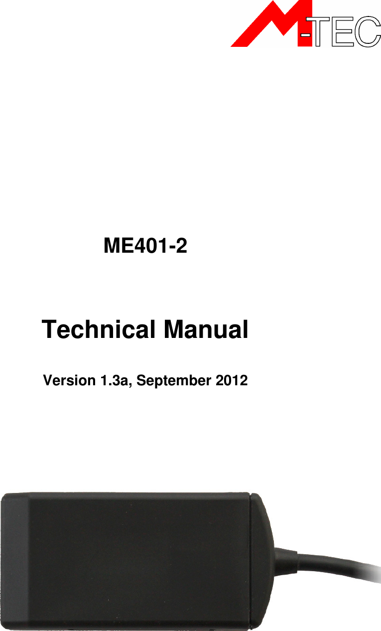
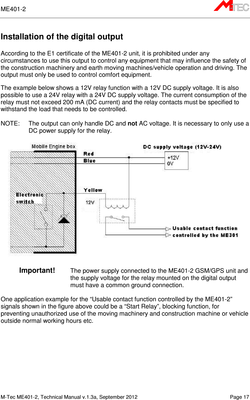
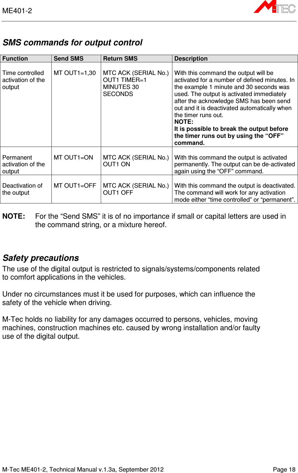
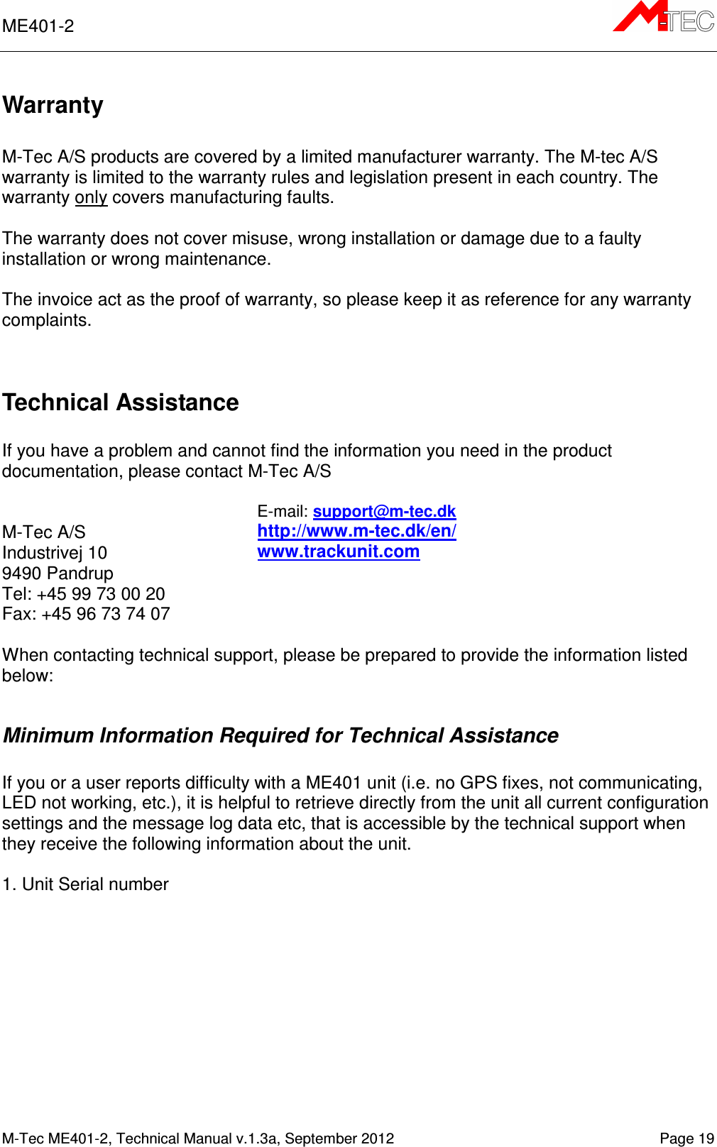
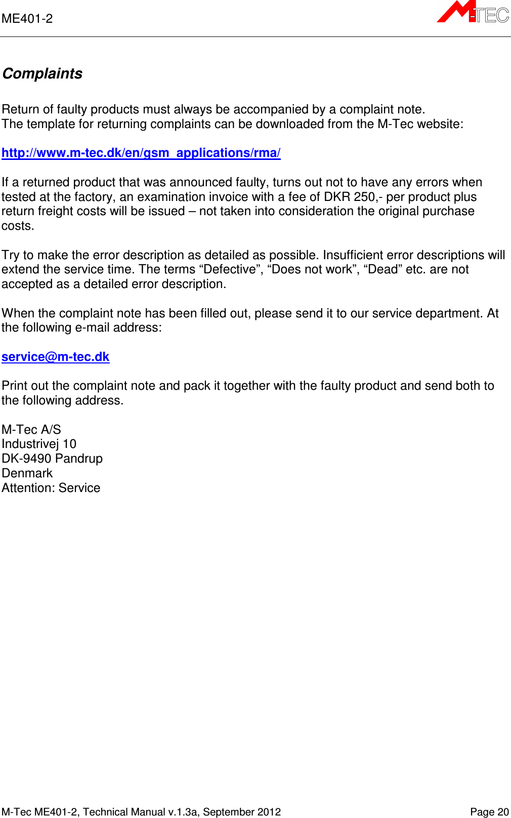
ME401 User Manual
User Guide
Navigation menu
Upload a User Manual
Namespaces
Wiki Guide
HTML
PDF
Info
Views
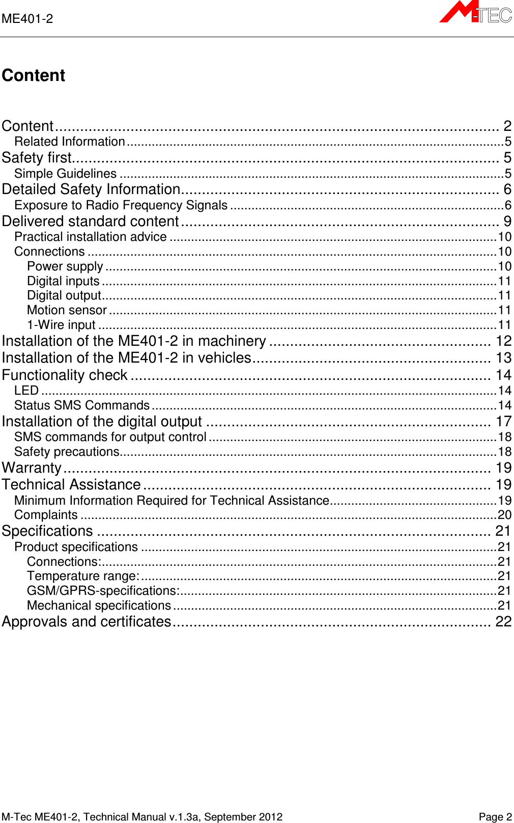
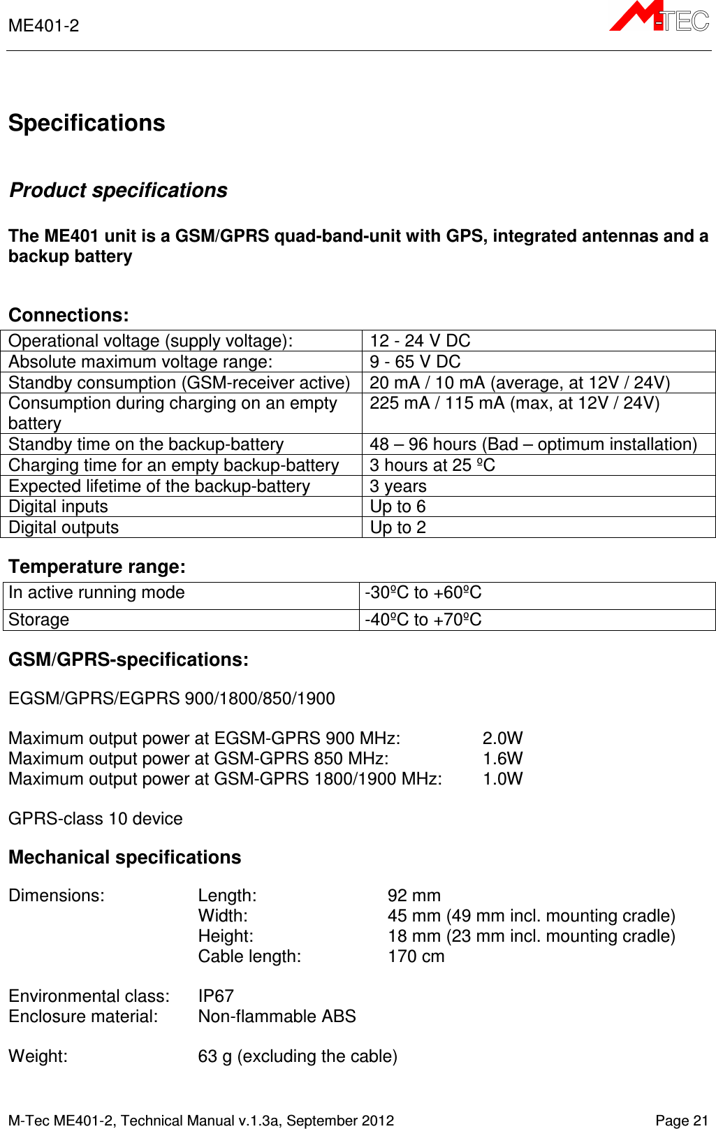
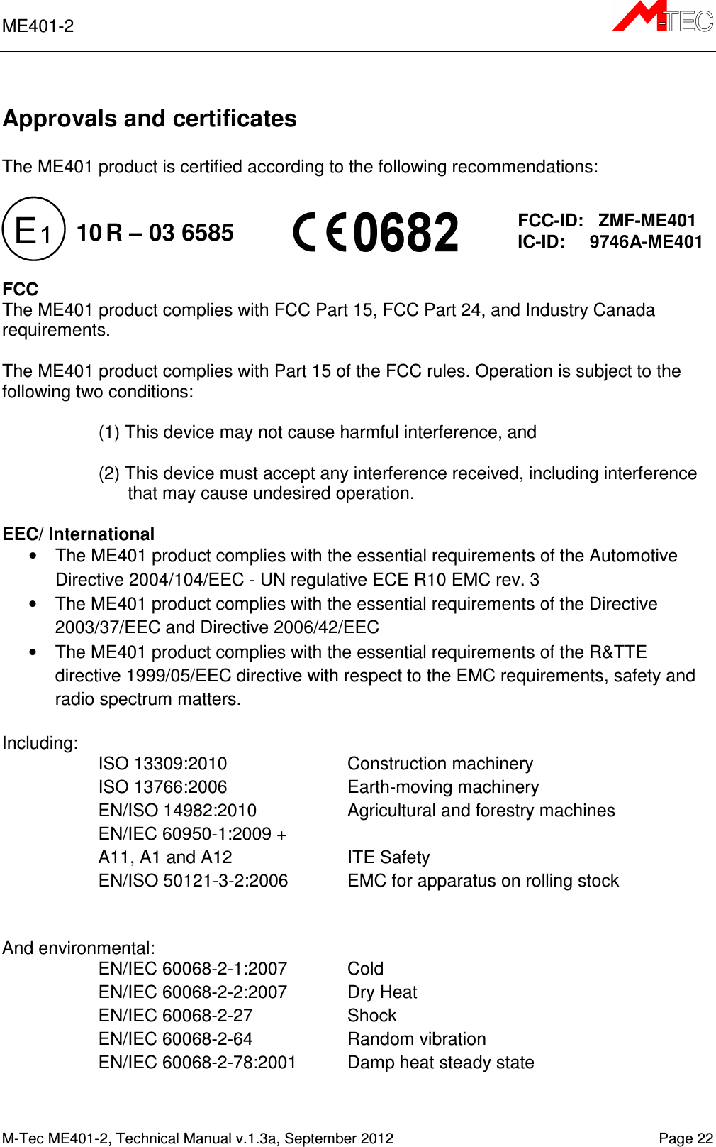
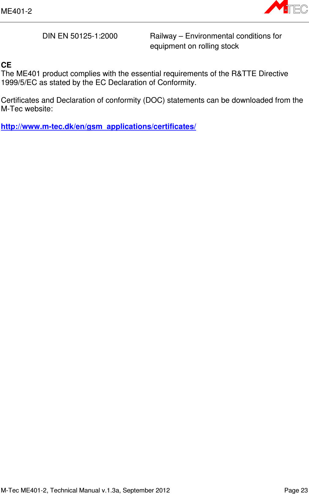
User Manual
Discussion / Help
Navigation