MOJIX STAR1000 RFID Reader User Manual
MOJIX, Inc. RFID Reader Users Manual
UserManual.wiki
>
MOJIX
>
STAR1000 User Manual
Users Manual
Navigation menu
Upload a User Manual
Namespaces
Wiki Guide
HTML
PDF
Info
Views
User Manual
Discussion / Help
Navigation


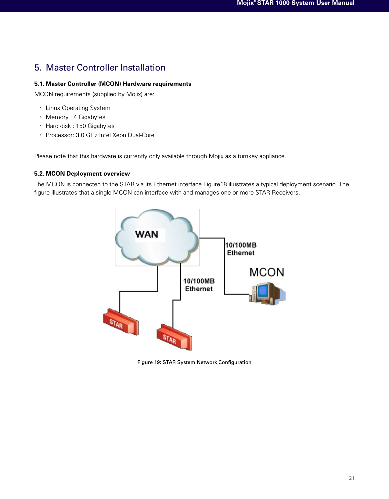
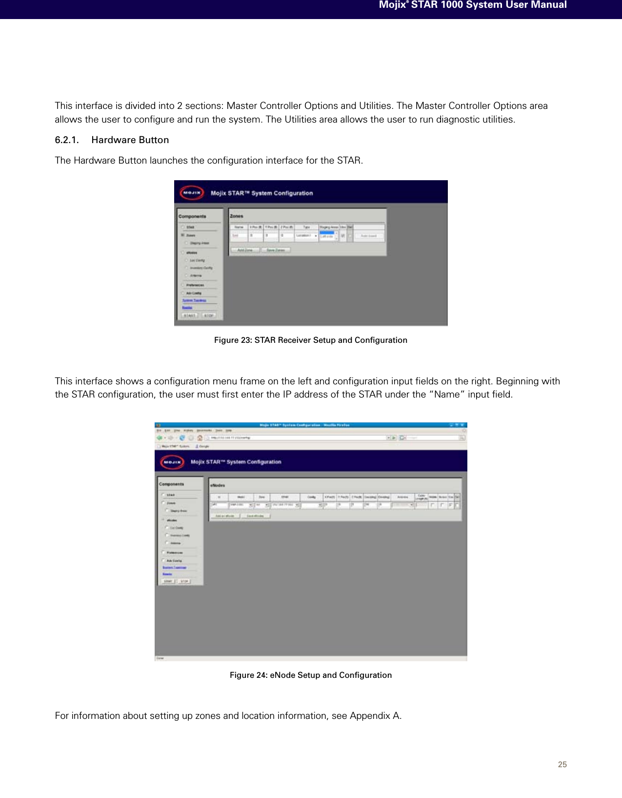
![24 Figure 21: Committing Network SettingsTo exit from a telnet session, the user must enter ‘ctrl-]’ and then type “quit” (ctrl = control key). 6.2. Graphical User InterfaceThe Web Graphical User Interface (Web GUI) provides the user a simplified HTTP based interface to configure and run the system. Currently, the only supported browsers are Mozilla Firefox and Microsoft Internet Explorer. To launch the Web GUI, enter the MCON IP address in the URL field of the browser. Not all screens are described in this version of documentation. The following screen is the landing page for the system. Figure 22: Main Web Control Landing PageFrom this interface, the user has access to various utilities for configuration and execution of the system. When presented with a Username and password, enter the default credentials as follows:Username: edisonPassword: m0j1xInc](https://usermanual.wiki/MOJIX/STAR1000/User-Guide-1139946-Page-24.png)