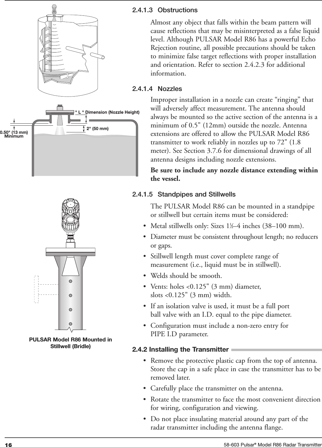
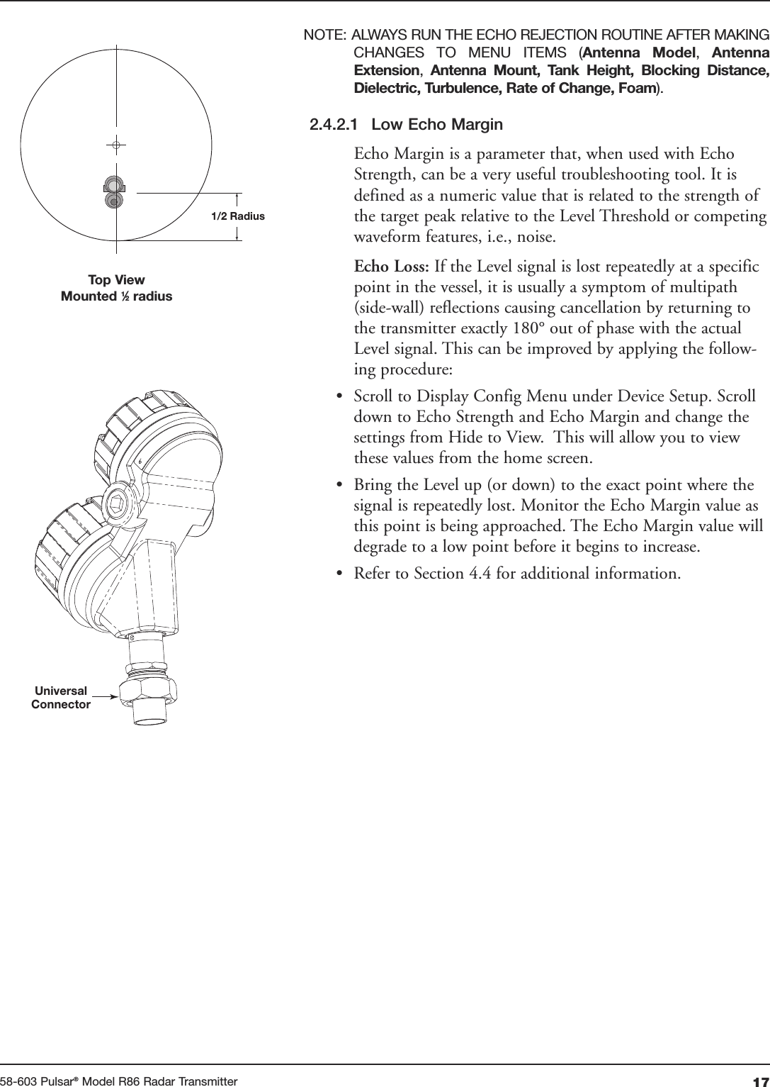
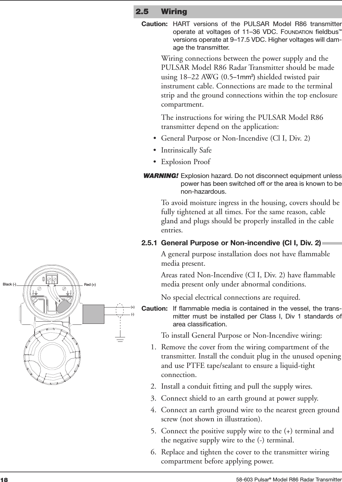
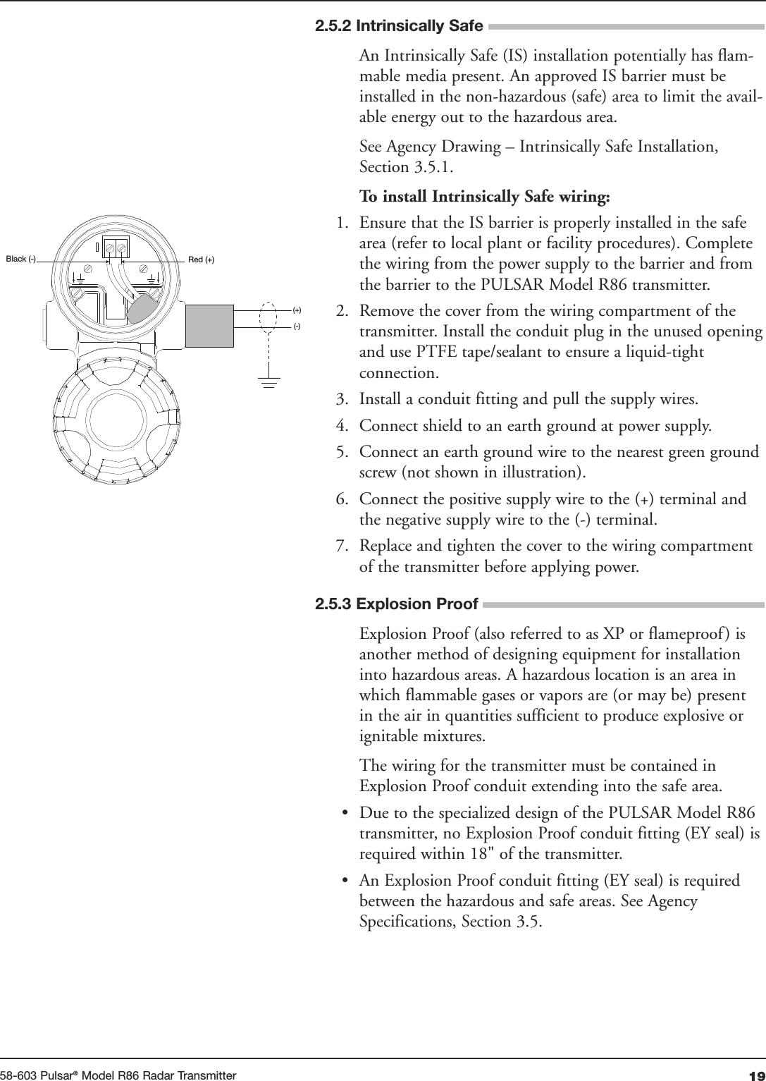
Magnetrol R86 Pulsar radar R86 26 GHz User Manual Layout 1
Magnetrol Pulsar radar R86 26 GHz Layout 1
UserManual.wiki
>
Magnetrol
>
R86 User Manual
>
User Manual Revised
Contents
1.
User Manual
2.
User Manual Revised
User Manual Revised
Navigation menu
Upload a User Manual
Namespaces
Wiki Guide
HTML
PDF
Info
Views
User Manual
Discussion / Help
Navigation
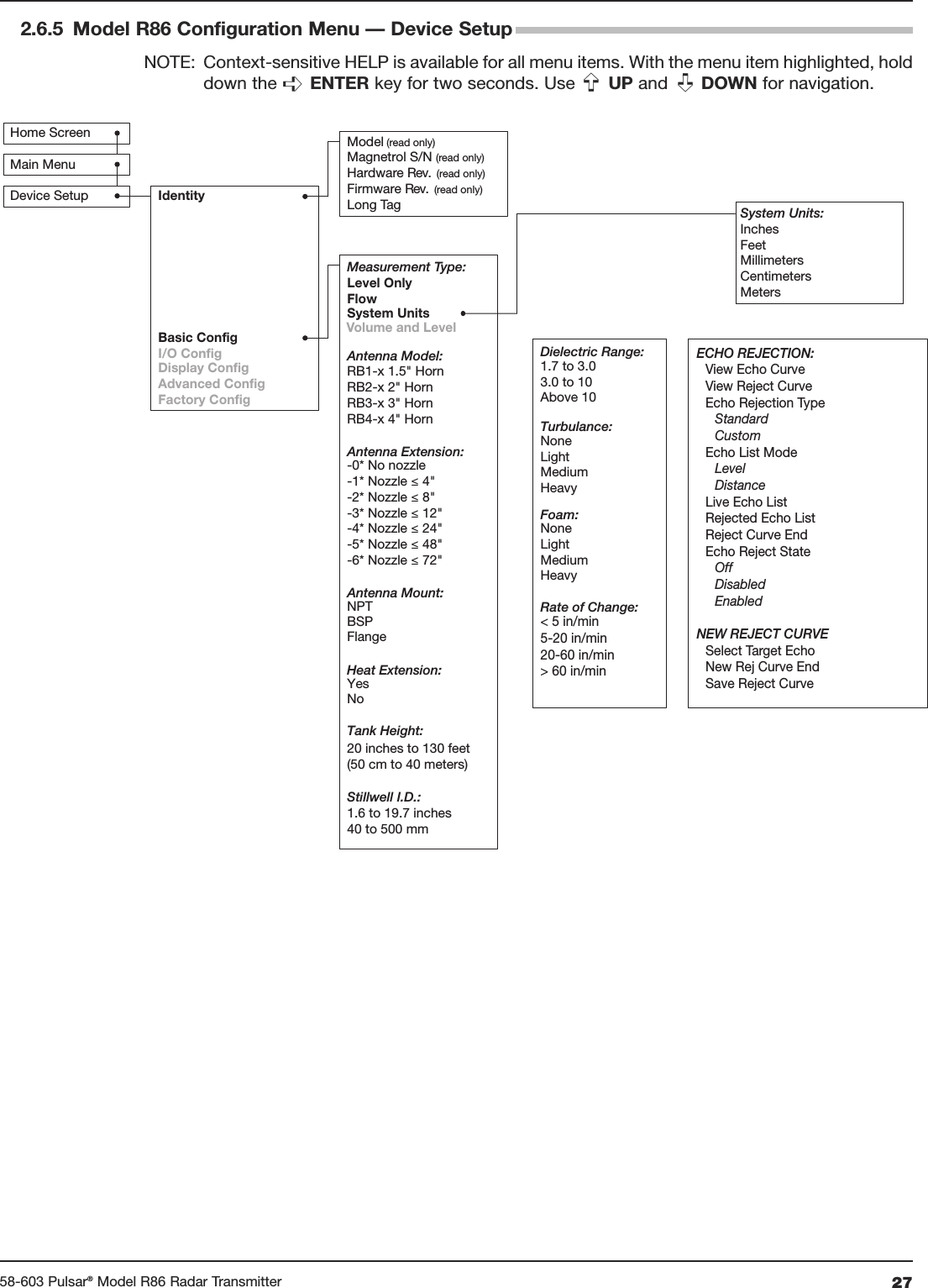
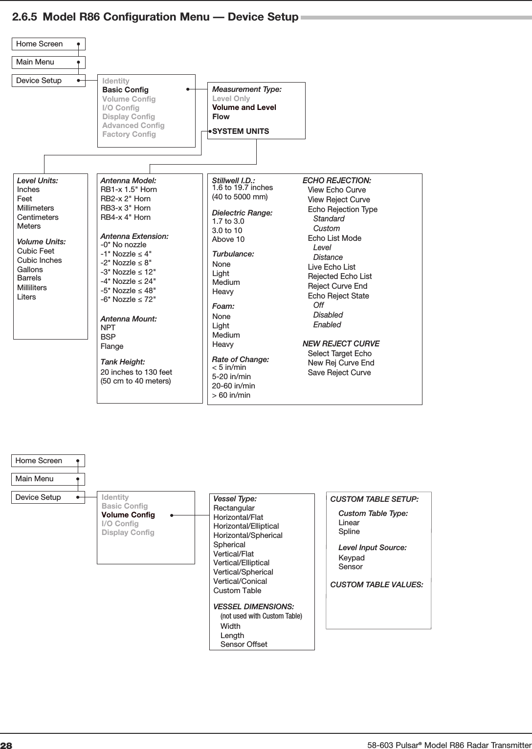
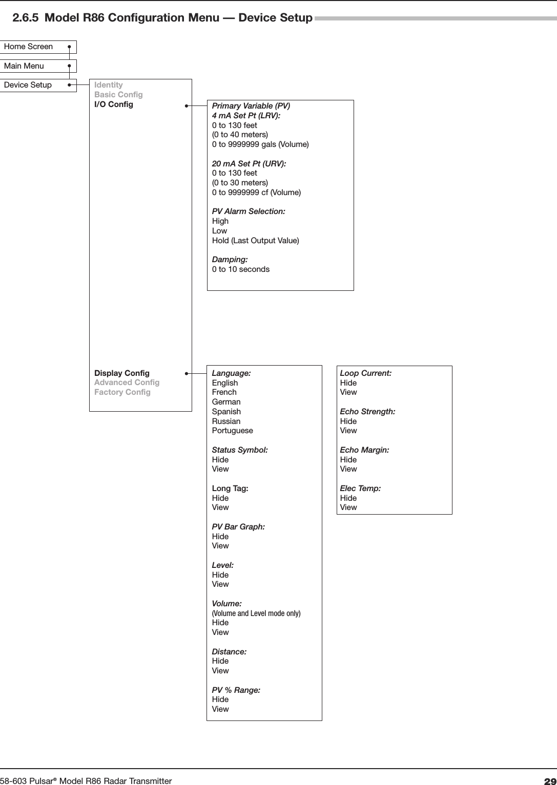
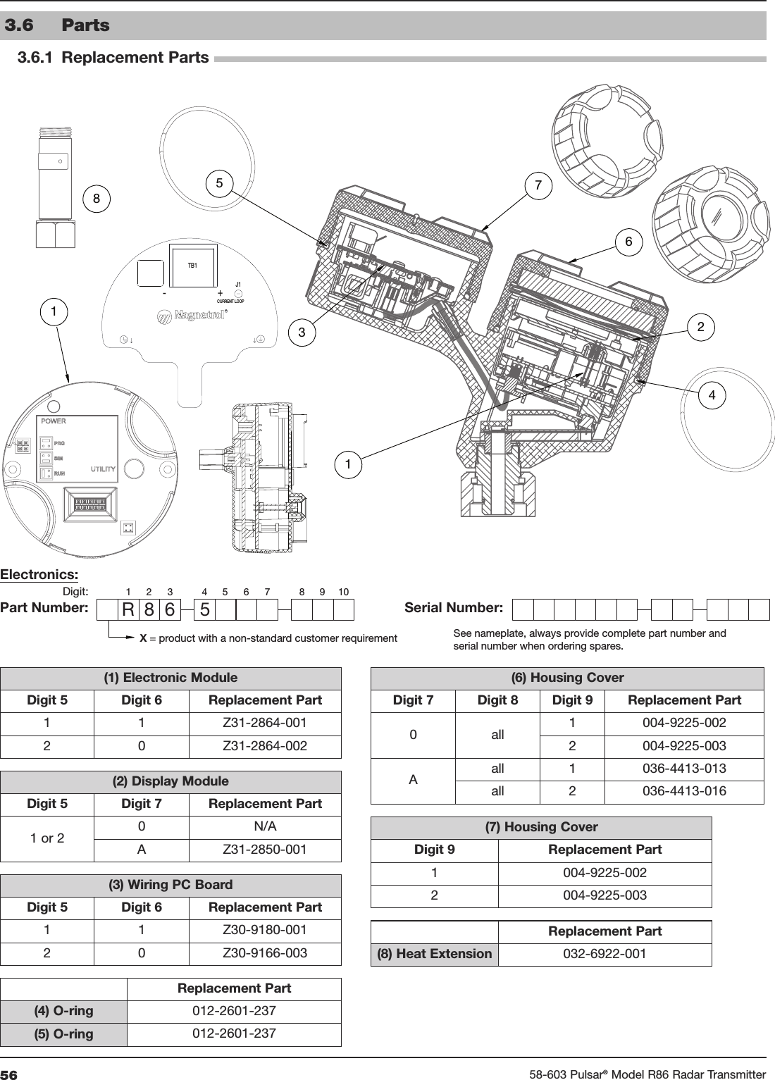
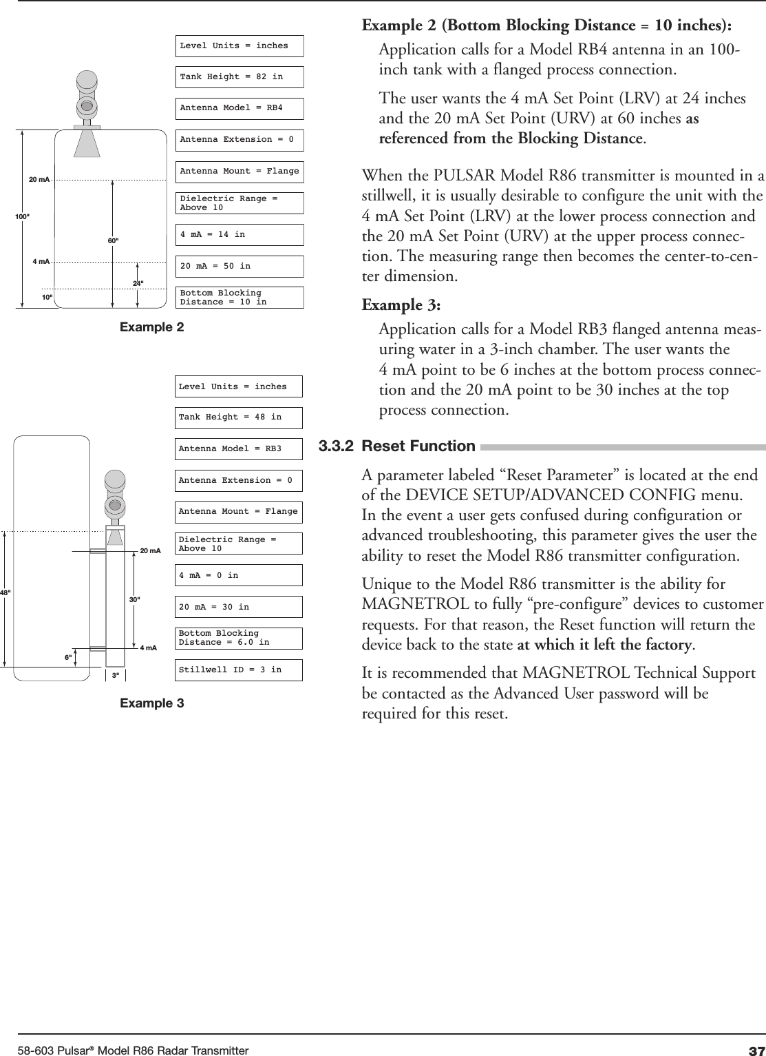
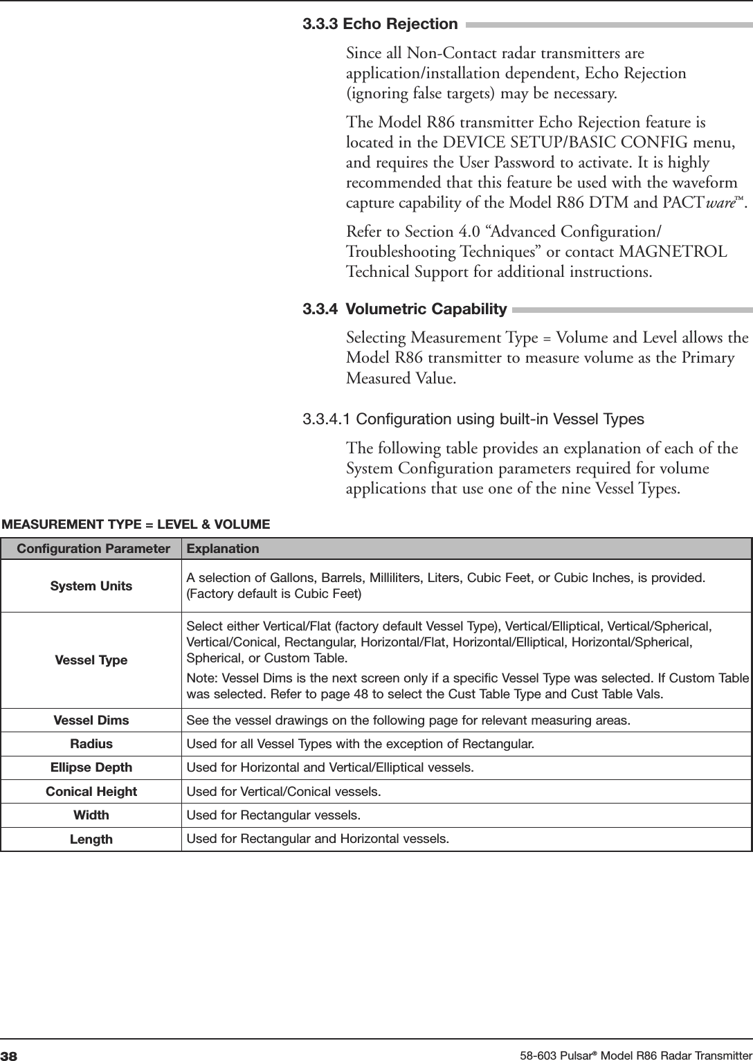
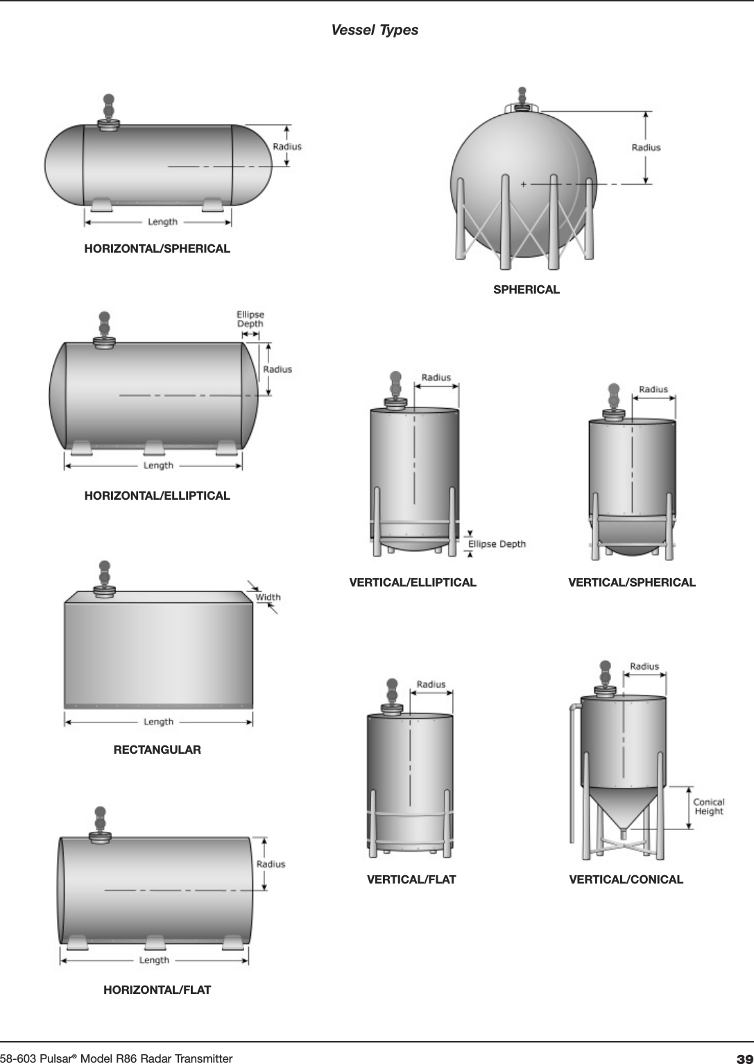
![30 58-603 Pulsar®Model R86 Radar TransmitterHome ScreenMain MenuDevice Setup IdentityBasic ConfigI/O ConfigDisplay ConfigAdvanced ConfigFactory ConfigSensitivity:50 to 200Top Blocking Distance:-12 to 120 inches (-30 cm to 3 meters)Bottom Blocking Distance:0 to 120 inches(0 to 3 meters)SAFETY ZONE SETTINGSSafety Zone Alarm:None3.6 mA22 mALatched 3.6 mALatched 22 mASafety Zone Height:(not used when Safety Alarm is None)2 inches to 20 feet(5 cm to 6 meters)Reset SZ Alarm (used when Safety Alarm is Latch 3.6 mA or Latch 22 mA)ECHO LOSS SETTINGS:Echo Loss Alarm:HighLowHold (Last Value Output)Echo Loss Delay:1 to 1000 secondsFailure Alarm Delay:0 to 5 secondsLevel Trim:-10 to +10 inches(-25 to +25 cm)THRESHOLD SETTINGSTarget Selection:First EchoLargest EchoTarget Thresh Mode:AutomaticFixed ValueTarget Thresh Value:0-99Base Threshold:0–99 ESUTIME VARIABLE GAIN:TVG Start ValueTVG Start LocationTVG End ValueTVG End Location# Run AverageMax Surface VelocityMax Level JumpEmpty State DelayCompound Peak LogicDisabledEnabledANALOG OUTPUT:HART Poll Address:0 to 63Loop Current Mode:Disabled (Fixed)Enabled (PV)[Fixed Current Value]4 to 20 mAADJUST ANALOG OUTPUT:Adjust 4mAAdjust 20mANew User Password:0 to 59,999CONFIG CHANGED:Indicator Mode:DisabledEnabledReset Config Chngd:Reset?NoYesReset Parameters:NoYes2.6.5 Model R86 Configuration Menu — Device Setup](https://usermanual.wiki/Magnetrol/R86.User-Manual-Revised/User-Guide-3371986-Page-30.png)
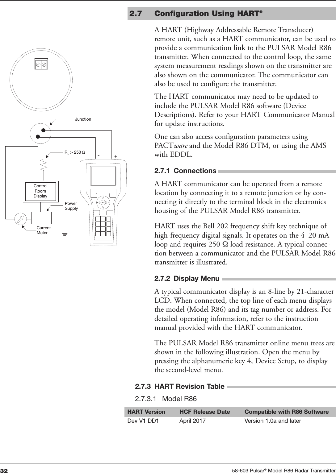
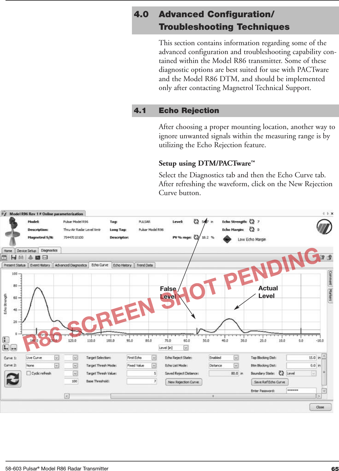
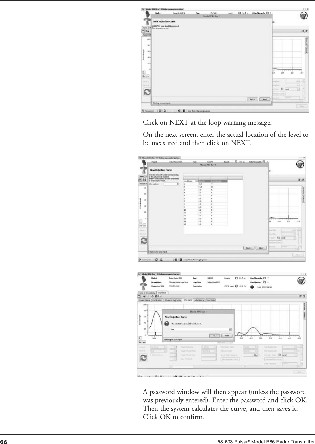
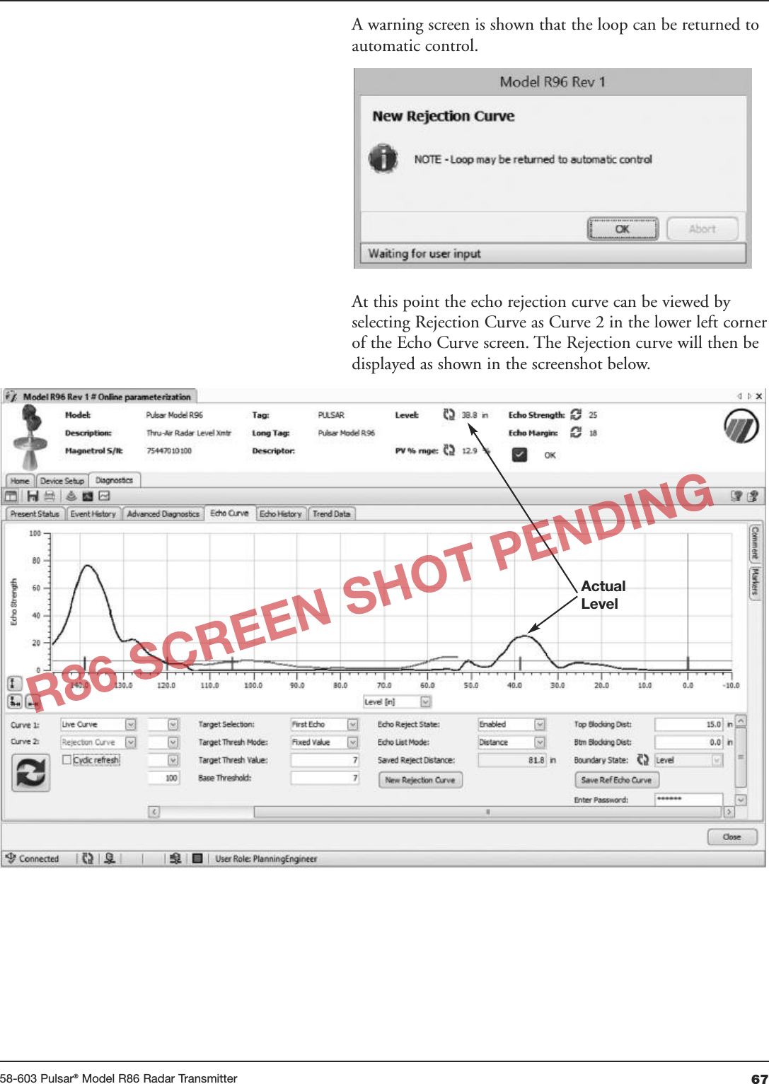
![5158-603 Pulsar®Model R86 Radar Transmitter3.4.5 Additional Diagnostic/Trouble Shooting Capabilities3.4.5.1 Echo History SetupThe Model R86 contains the unique and powerful featurethat allows waveforms to be automatically captured basedon Diagnostic Events, Time or both. This menu containsthose parameters that configure that feature.Eleven (11) waveforms can be saved directly into the trans-mitter. • Nine (9) Troubleshooting Curves • One (1) Echo Rejection Curve• One (1) Reference Curve3.4.5.2 Event HistoryAs a means for improved troubleshooting capability, arecord of significant diagnostic events is stored with timeand date stamps. A real-time on-board clock (which mustbe set by the operator), will maintain the current time.3.4.5.3 Context-sensitive HelpNOTE: Context-sensitive HELP is available for all menu items. With themenu item highlighted, hold down the ➪ENTER key for twoseconds. Use UP and DOWN for navigation.Descriptive information relevant to the highlighted parameterin the menu will be accessible via the local display andremote host interfaces. This will most often be a parameter-related screen, but could also be information about menus,actions (for example, Loop [Analog Output] Test, resets ofvarious types), diagnostic indicators, etc. For example: Dielectric Range — Selects the range boundingthe dielectric constant of the medium in vessel. Some rangesmay not be selectable depending on the antenna model.3.4.5.4 Trend DataAnother feature of the Model R86 is the ability to log severalmeasured values (selectable from any of the primary,secondary, or supplemental measured values) at a config-urable rate (for example, once every five minutes) for aperiod ranging from several hours to a number of days(depending on the configured sample rate and number ofvalues to be recorded). The data will be stored in non-volatile memory in the transmitter with date and timeinformation for subsequent retrieval and visualization usingthe associated Model R86 DTM.TREND DATA – A 15-minute trend of the PV can bedisplayed on the LCD.➪➪](https://usermanual.wiki/Magnetrol/R86.User-Manual-Revised/User-Guide-3371986-Page-51.png)