Medtronic 8880T2 8880T2 User Manual
Medtronic, Inc. 8880T2
UserManual.wiki
>
Medtronic
>
8880T2 User Manual
User Manual
Navigation menu
Upload a User Manual
Namespaces
Wiki Guide
HTML
PDF
Info
Views
User Manual
Discussion / Help
Navigation


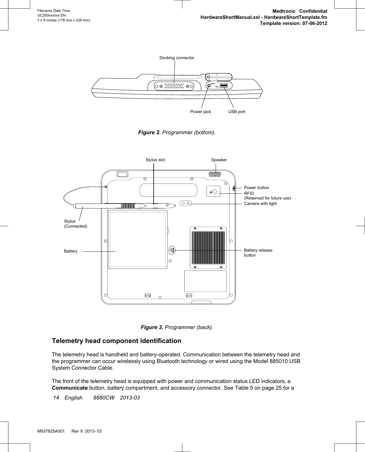
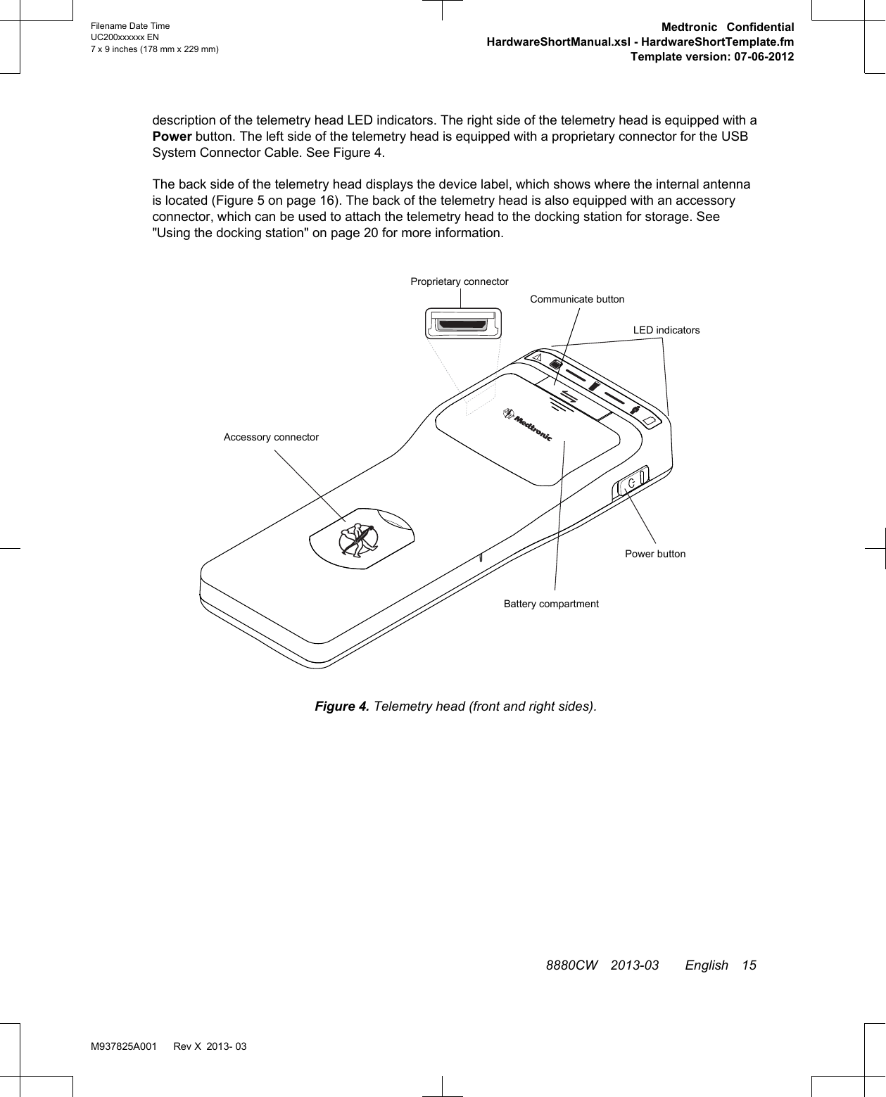
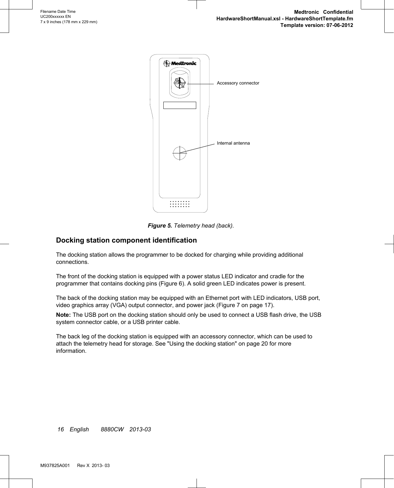
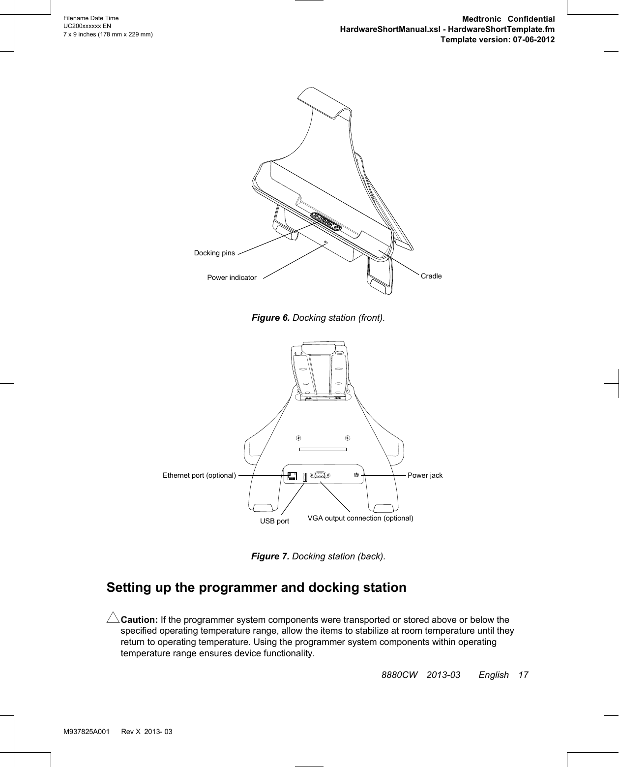
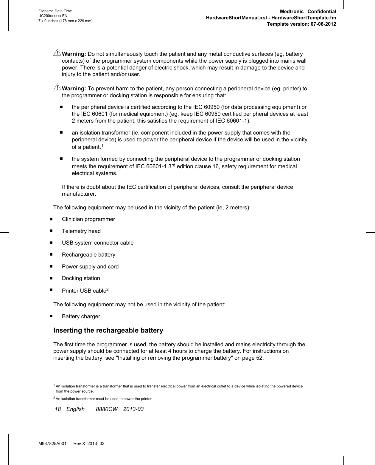
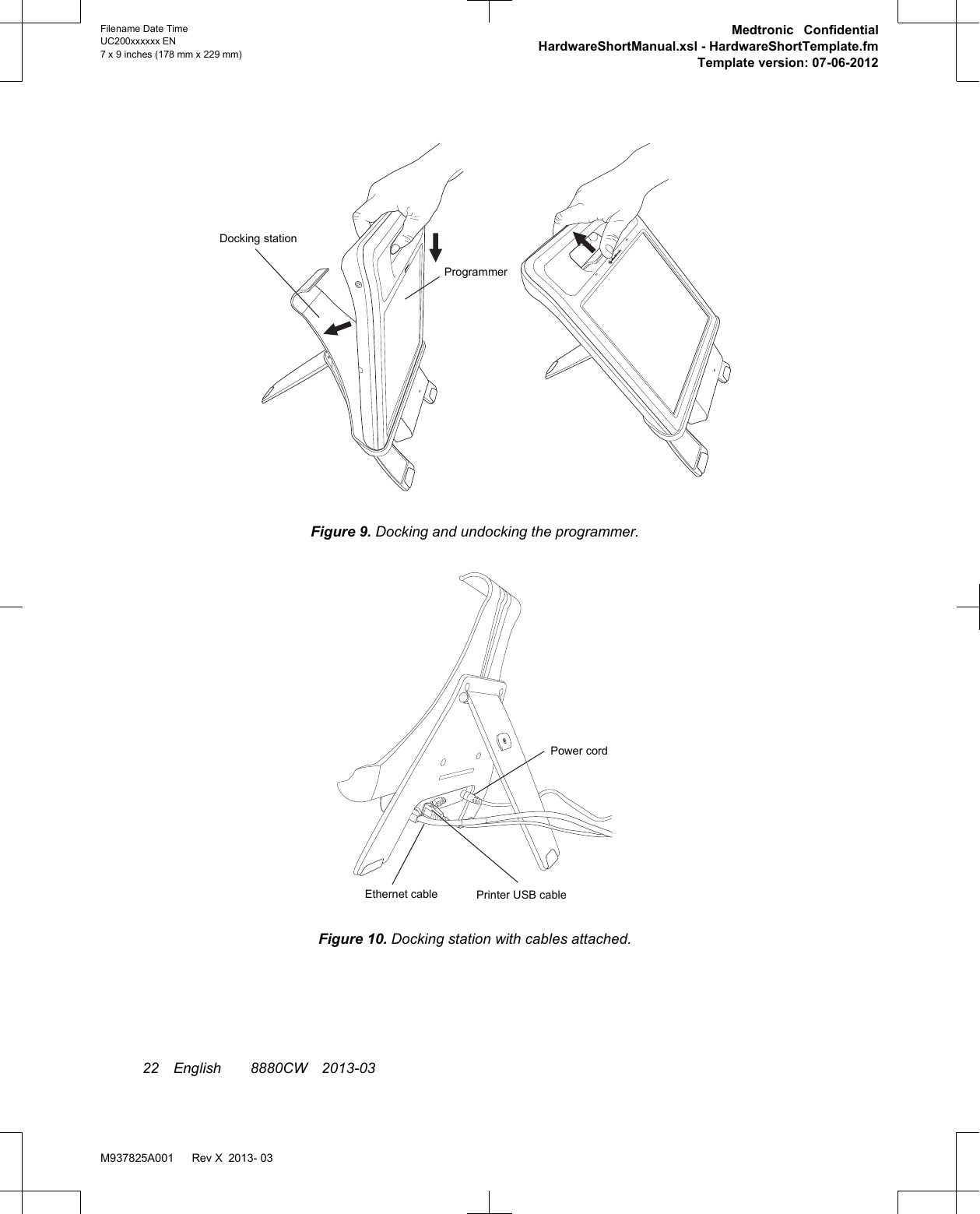
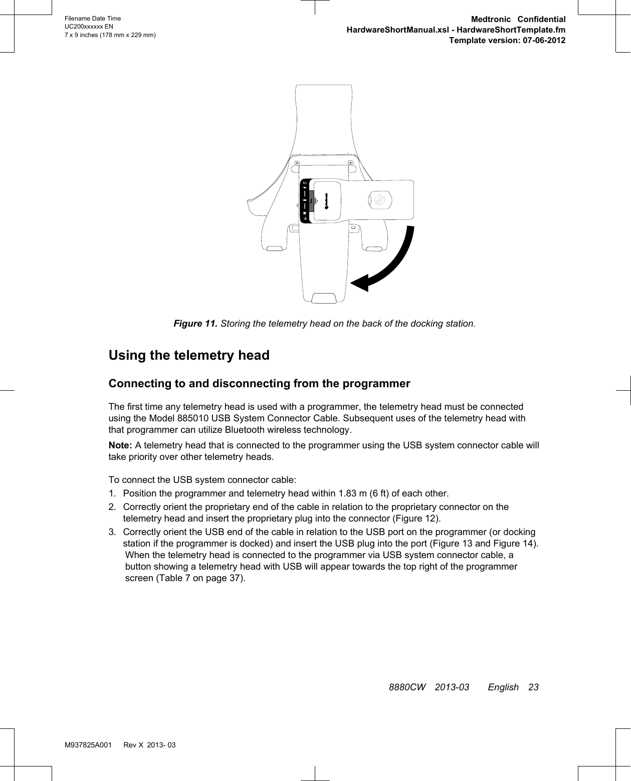
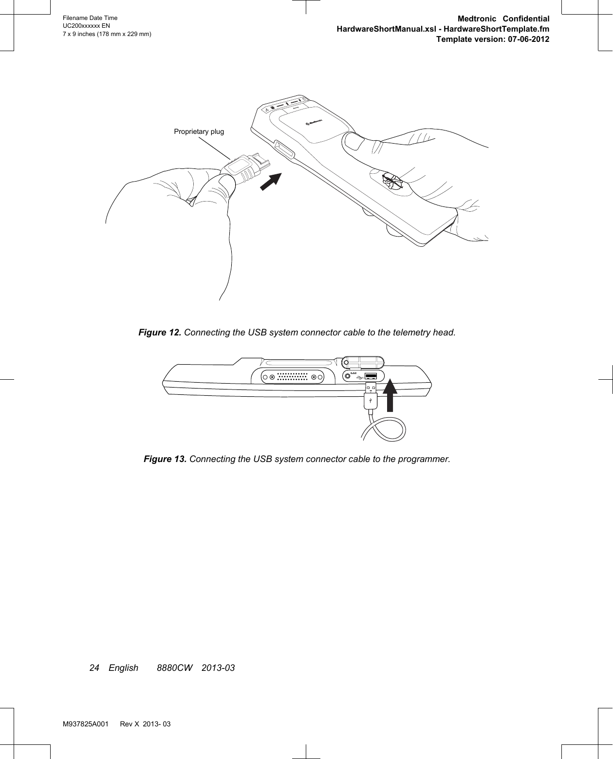
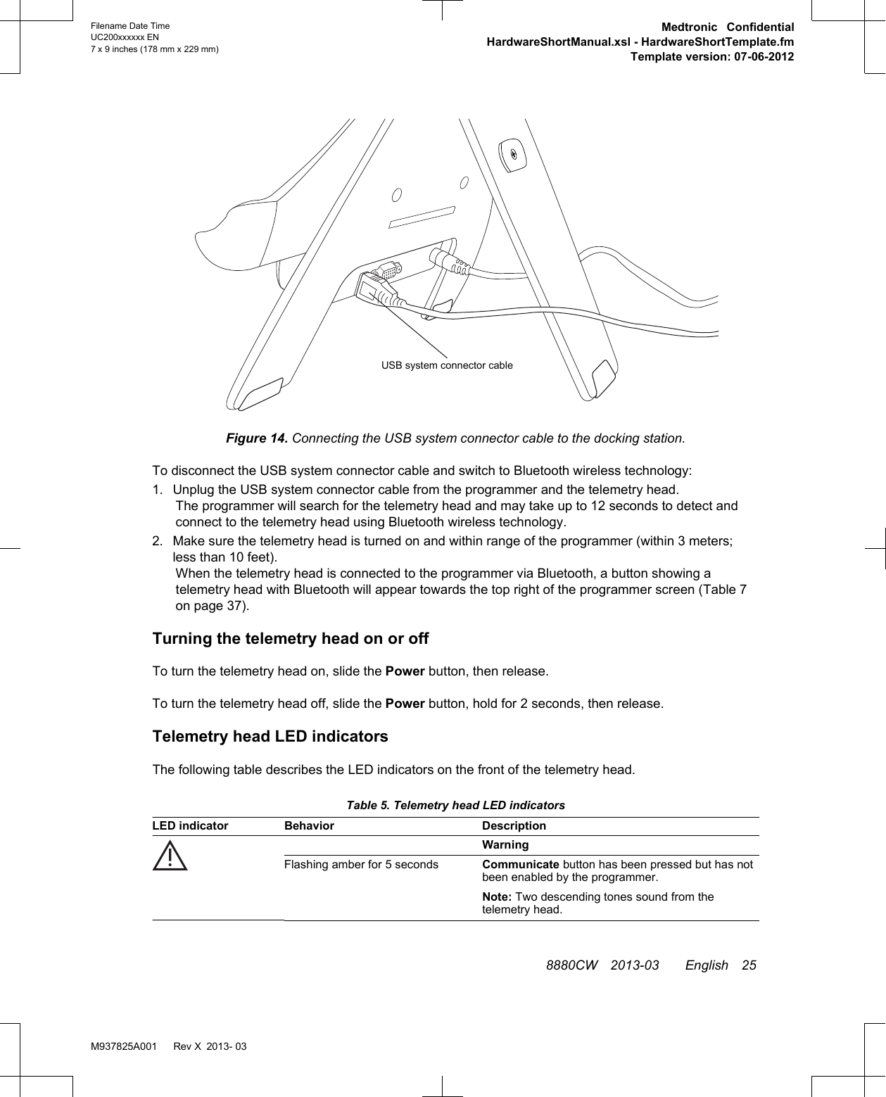
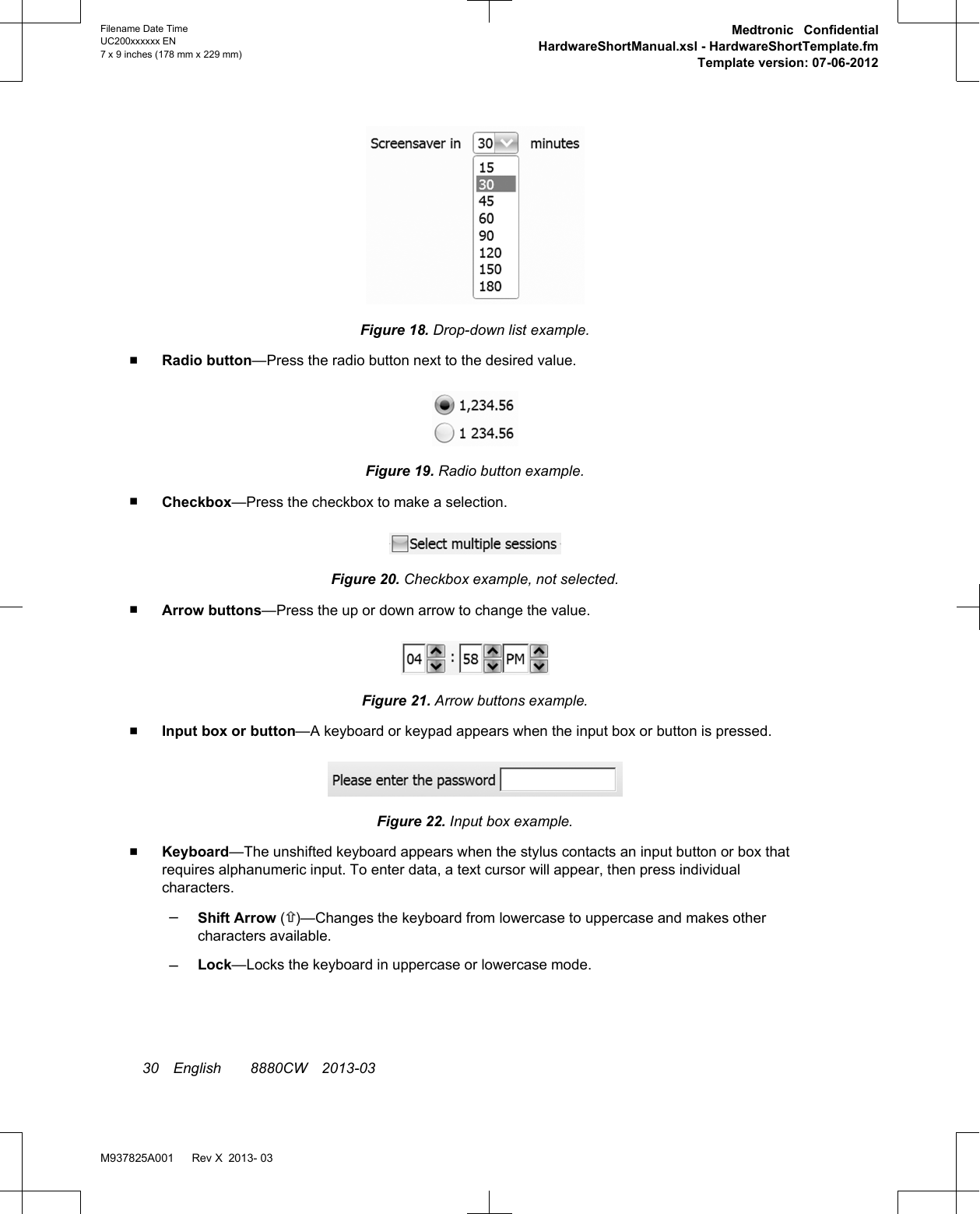

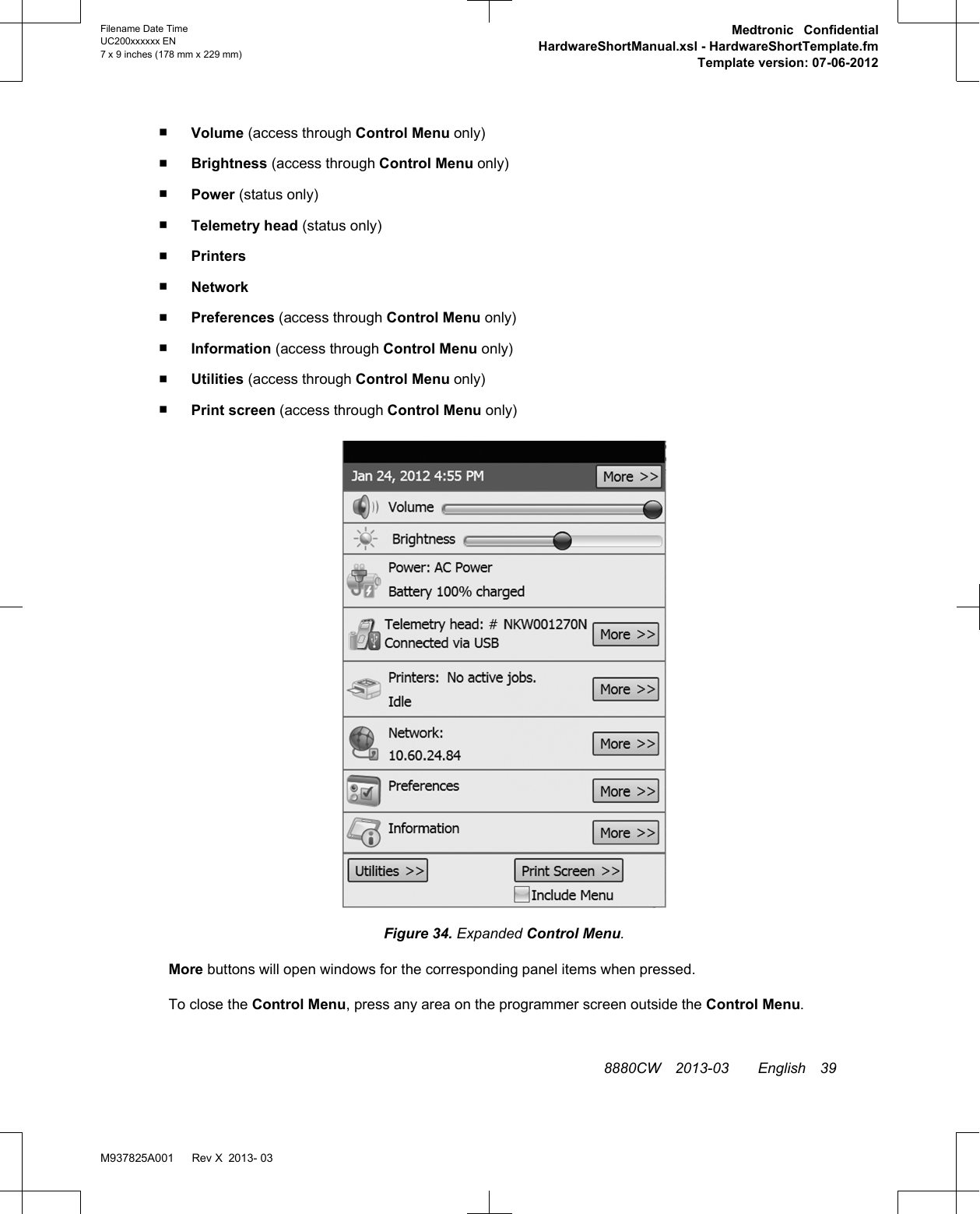
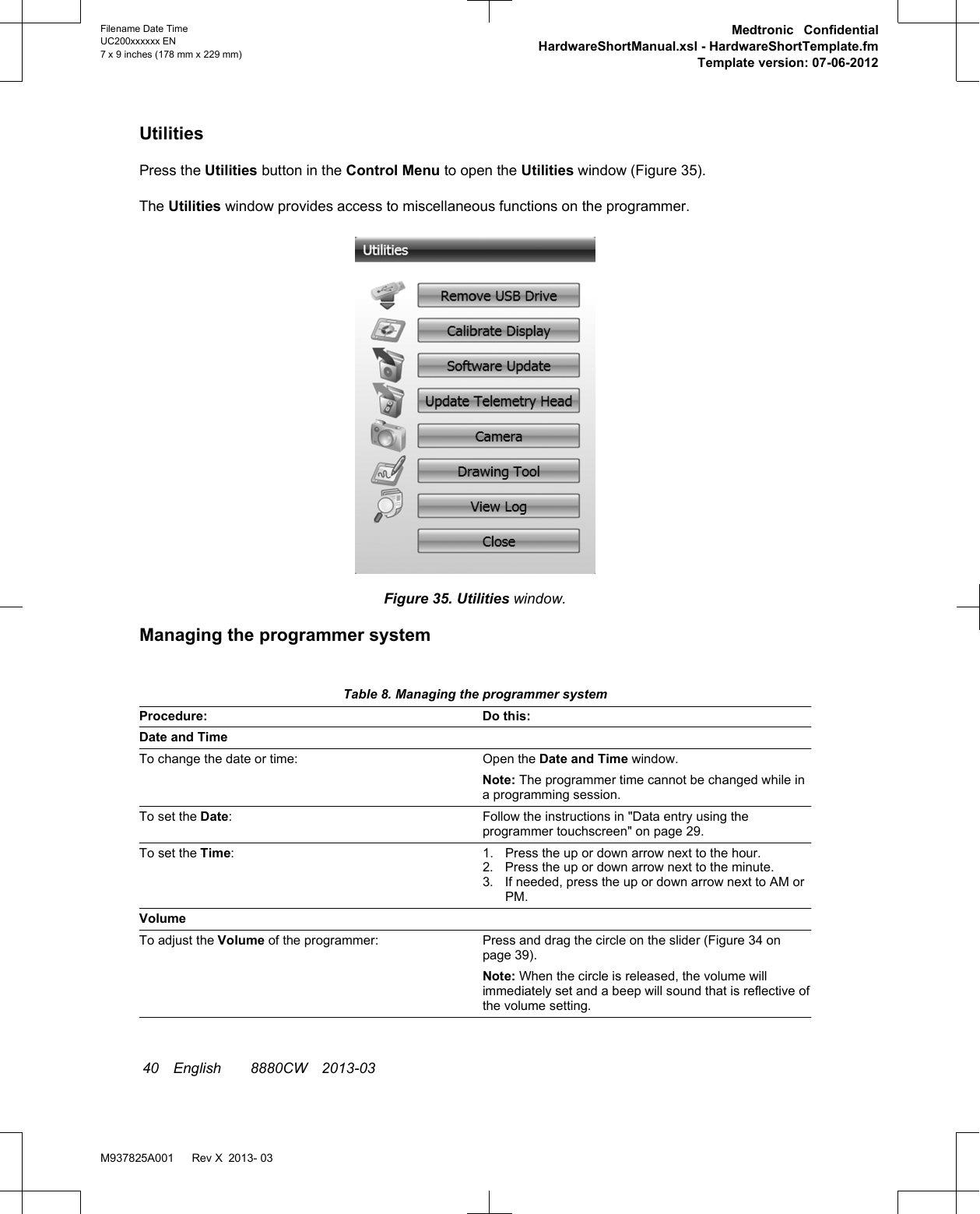
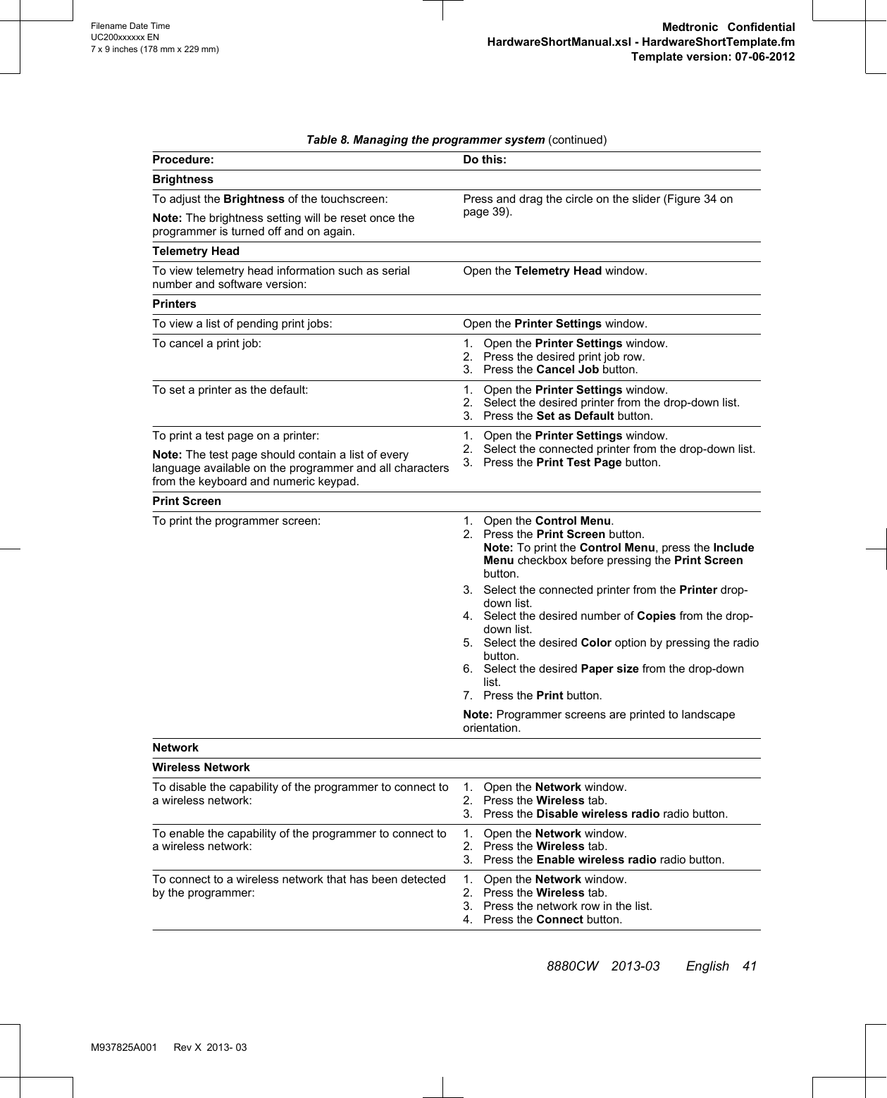
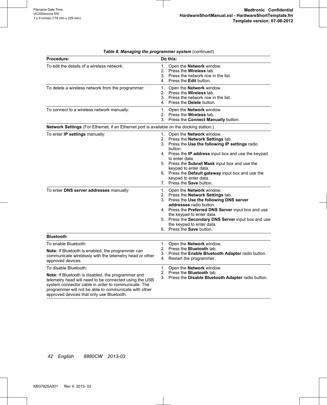
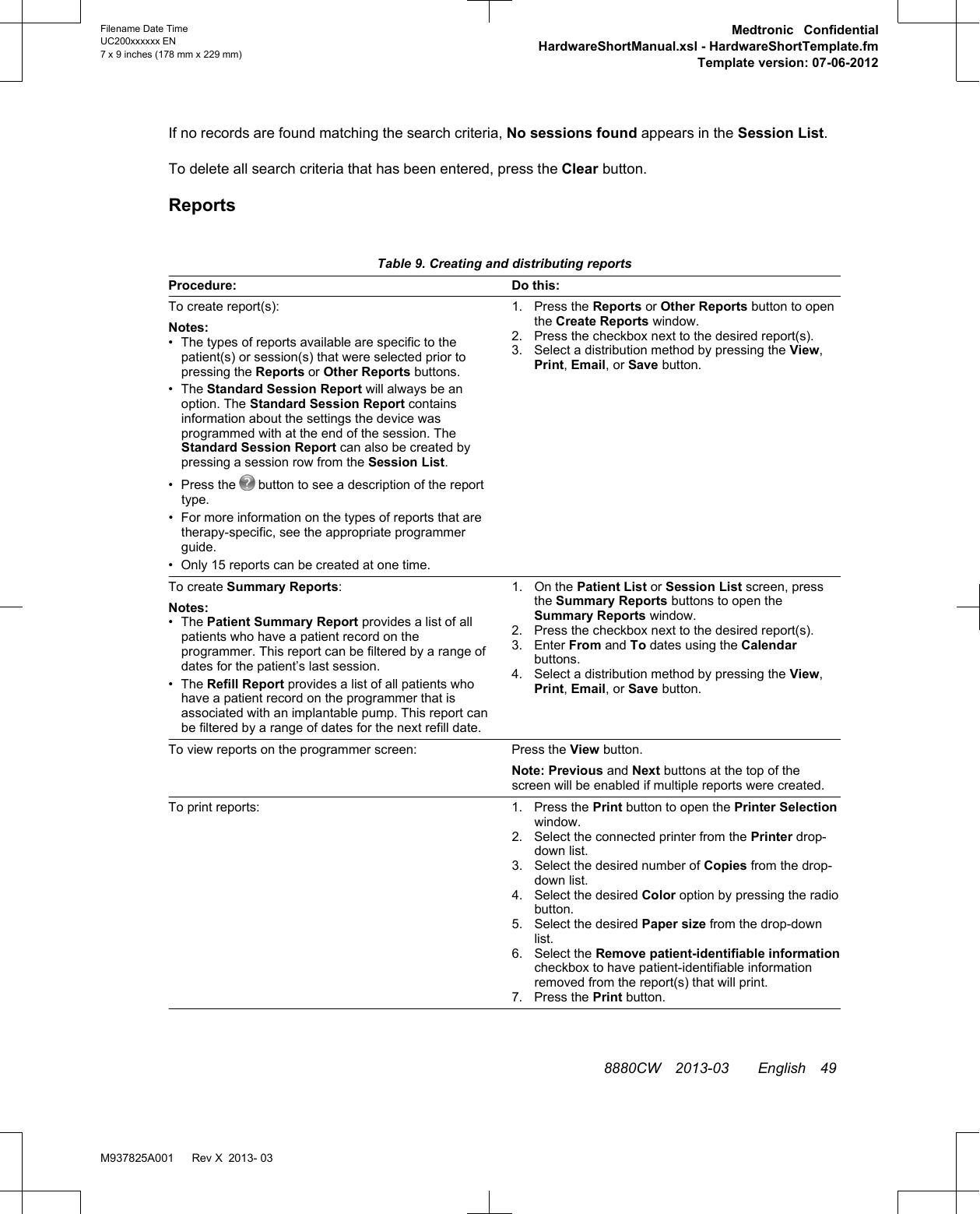
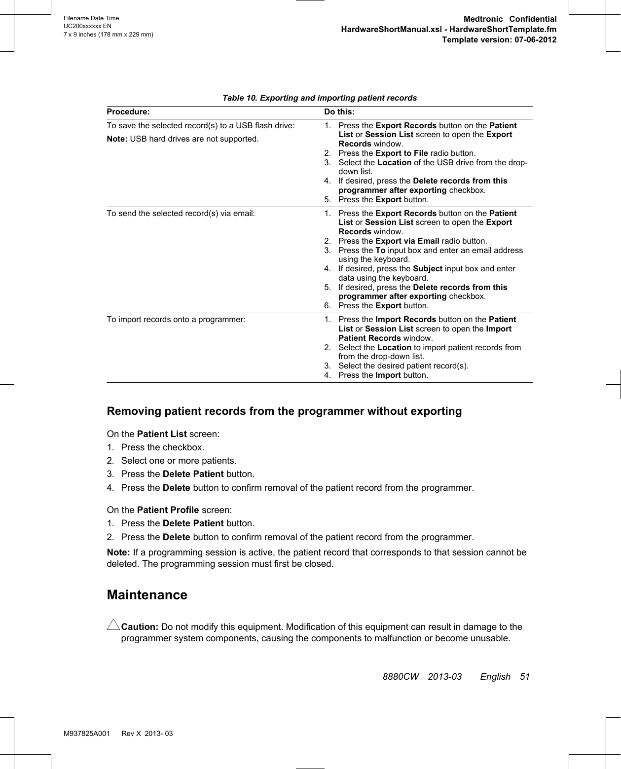
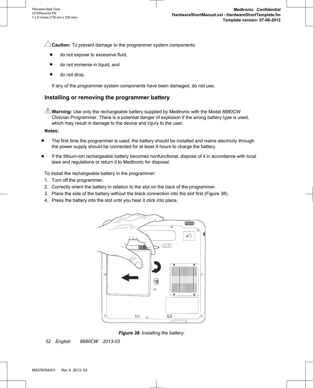
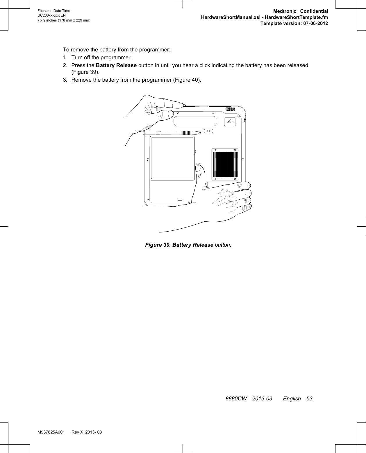
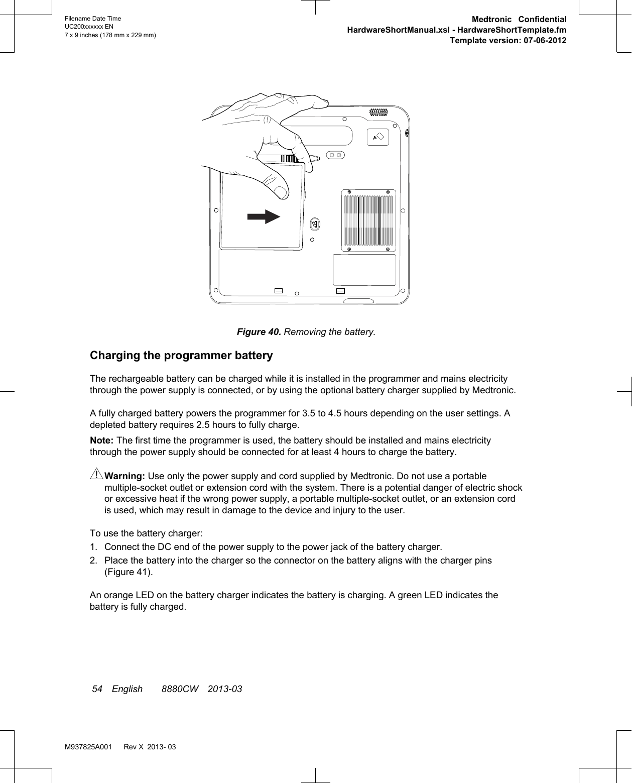
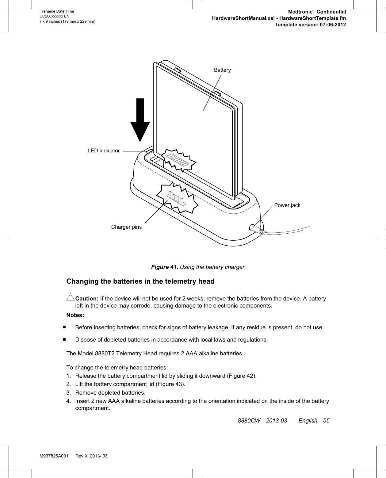
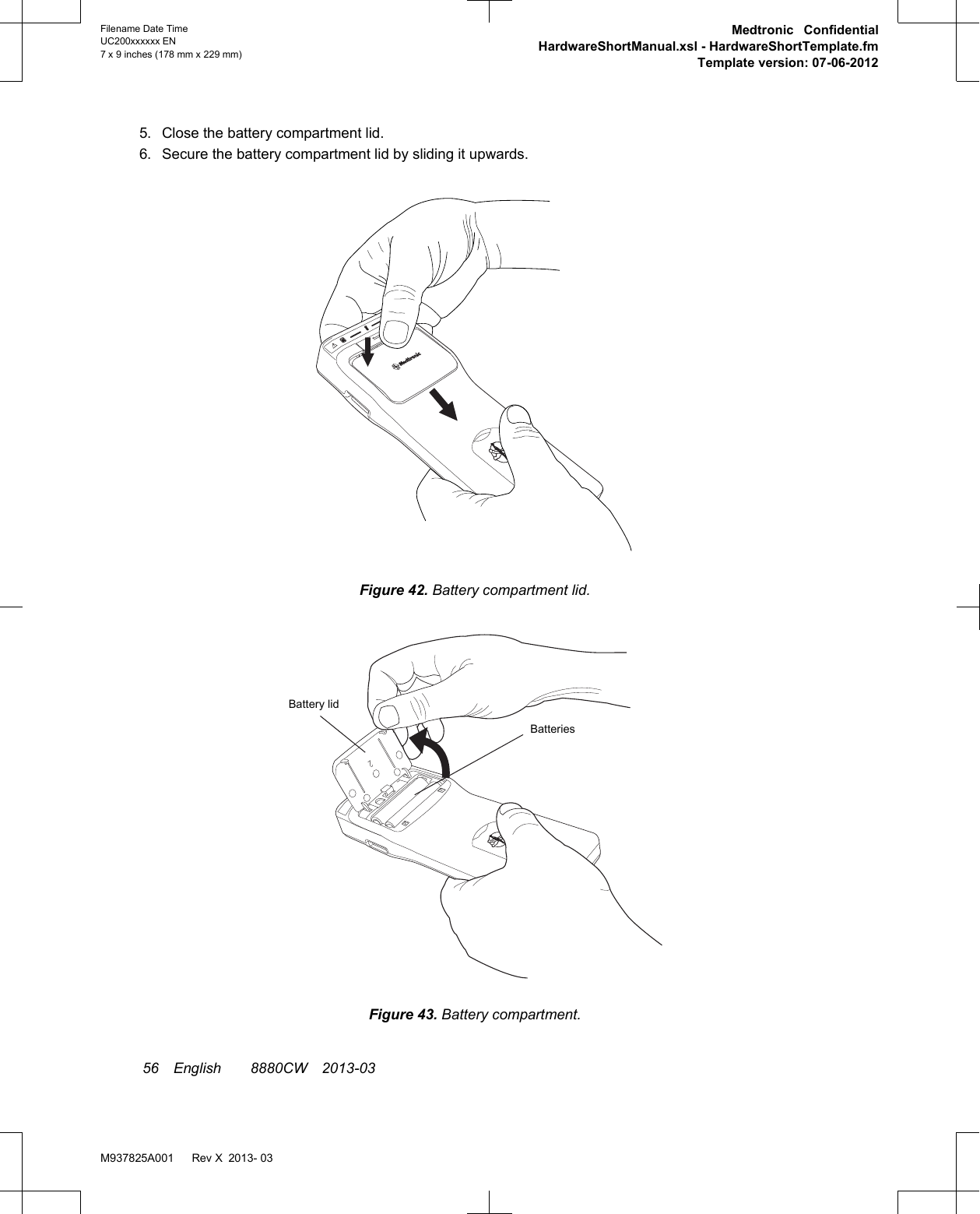
![Table 9. Creating and distributing reports (continued)Procedure: Do this:To send reports via email:Notes:• Email network settings need to be set up in order tosend email. See "Managing the programmer system"on page 40.• Emailed reports are not encrypted. To maintain dataencryption, see "Moving patient records from oneprogrammer to another".1. Enter the email address(es) to send the report(s) toby pressing the To input box and using the keyboard.2. Press the Email button to open the Compose Emailwindow.3. Press the Subject input box and enter data using thekeyboard.4. Press the large input box and enter other notes usingthe keyboard.5. Select the desired File Format by pressing the radiobutton.6. Select the Remove patient-identifiable informationcheckbox to have patient-identifiable informationremoved from the report(s) that will be sent via email.7. Press the Send button.To save reports to a USB flash drive or to a networklocation:Notes:• Network location settings need to be set up in order tosave to a network location. See "Managing theprogrammer system" on page 40.• USB hard drives are not supported.• Saved reports are not encrypted. To maintain dataencryption, see "Moving patient records from oneprogrammer to another".1. Press the Save button to open the Save window.2. Select the desired Location from the drop-down list.3. Select the desired File Format by pressing the radiobutton.4. Select the Remove patient-identifiable informationcheckbox to have patient-identifiable informationremoved from the report(s) that will be saved.5. Press the Save Files button. Moving patient records from one programmer to anotherPatient records can be exported from one Model 8880CW Clinician Programmer and imported ontoanother. Patient records can be exported by being saved to a USB flash drive or sent via email. Patientrecords can be imported from a USB flash drive or network location. Once the patient records areimported, they can be accessed using the Patient Data Center.Notes:▪Exported patient records are encrypted and can only be read by being imported onto anotherprogrammer.▪Records will be exported in the following file format: [Month-Day-Year-HHMMSS].mdt, whereHHMMSS is the time that the file was exported in hours, minutes, and seconds.▪Information on the programmer will be overwritten by information that is imported onto theprogrammer. This applies to patient information such as patient address or patient name. Nosession data will be overwritten.▪Importing records will not create duplicate records. Records are determined based on the serialnumber of the primary implantable device.50 English 8880CW 2013-03Filename Date TimeUC200xxxxxx EN7 x 9 inches (178 mm x 229 mm)Medtronic ConfidentialHardwareShortManual.xsl - HardwareShortTemplate.fmTemplate version: 07-06-2012M937825A001 Rev X 2013- 03](https://usermanual.wiki/Medtronic/8880T2/User-Guide-1814953-Page-51.png)